Embed Size (px)
Citation preview
UNCLASSIFIED
AD NUMBER
AD020374
NEW LIMITATION CHANGE
TOApproved for public release, distributionunlimited
FROMDistribution authorized to U.S. Gov't.agencies and their contractors;Administrative/Operational Use; AUG 1953.Other requests shall be referred to Schoolof Aviation Medicine, Randolp AFB, TX.
AUTHORITY
711th HPW/OMA [STINFO] ltr dtd 4 Feb 2009
THIS PAGE IS UNCLASSIFIED

Armed Services Technical Information Agenc
Ia
NOTICE: WHEN GOVERNMENT OR OTHER DRAWINGS, SPECIFICATIONS OR OTHER DATAARE UED FOR ANY PURPOSE OTHER THAN IN CONNECTION WITH A DEFINITELY RELATEDGOVERNMENT PROCUREMENT OPERATION, THE U. S. GOVERNMENT THEREBY INCURSNO RESPONSIBILITY, NOR ANY OBLIGATION WHATSOEVER; AND THE FACT THAT THEGOVERNMENT MAY HAVE FORMULATED, FURNISHED, OR IN ANY WAY SUPPLIED THESAID DRAWINGS, SPECIFICATIONS, OR OTHER DATA IS NOT TO BE REGARDED BYIMPLICATION OR OTHERWISE AS IN ANY MANNER LICENSING THE HOLDER OR ANY OTHERPERSON OR CORPORATION, OR CONVEYING ANY RIGHTS OR PERMISSION TO MANUFACTURE,USE OR SELL ANY PATENTED INVENTION THAT MAY IN ANY WAY BE RELATED THERETO.
Reproduced 6yDOCUMENT SERVICE CENTER
KNOTT BUILDING DAYT
NCLA SIFIEE)- - t- --
UNITED AIR UNIVERSITYSTATES
AIR!5e ooFORCEC-. AVIATION
MEDICINEPHYSICS AND ENGINEERING OF RAPID DECOMPRESSION
A General Theory of Rapid Decompression
PROJECT NUMBER 21-1201-0008
REPORT NUMBER 3
PROJECT REPORT
•......... I...................... ................ ....................................
USAF School of Aviation Medicine, Project No. 21-1201-0008, Report No. 3.Physicx and En 4 ineering of Rapid Decompression: A.General Theory of
Rapid Decompression.
Fritz Haber and Hans Georg Clamann, USAF School of Aviation Medicine,Roadolph Field, Texas.
29 pp & iii. 13 illus. 27 cm. UNCLASSIFIEDTheoretical considerations indicate that the analysis of the entire process
of rapid decompression can be split into two parts. The first one includesthe geometrical and aerodynamic quantities of the system under considerationand can best be represented by a term which is called time-constanh, be-cause it sets the time scale fgr the entire process. The second part containsa pressure function, which determines the dependence of the process uponthe pressures involved. The initial rate of pressure change is discussedand presented in a similar fashion. The experiments are in good agreementwith the theory.1. Physiology. 2. Decompression.
I. Haher, Fritz 11. Clamann, Hans Georg August 1953
o ...... ,...,. .............. a..... ............ ........
USAF School of Aviation Medicine, Project No. 21-1201-008, Report No. 3.Physics and En4ineering of Rapid Decompression: A.Genersl Theory of
Rapid Decompression.Fritz Haber and Hans Georg Clamann, USAF School of Aviation Medicine,
Randolph Field, Texas.29 pp & iii. 13 illus. 27 cm. UNCLASSIFIED
Theqeetical considerations indicate that the analysis of the entire processof rapid decompression can be split into two parts. The first one includesthe geometrical and aerodynamic quantities of the system under considerationand can beat be represented by a term which is called uzms.constant, be-cause it sets the time scale for the entire process. The second part containsa pressure function. which determines the dependence of the process uponthe pressures involved. The initial rate of pressure chan#e is discussedand presented in a similar fashion. The experiments are in good agreementwith the theory.1. Physiology. 2. Decompression.
I. Haer, Fritz II. Clamann, Hans Georg August 1953
....................................... .................. .................
USAF School of Aviation Medicine, Project No. 21-1201-0008, Report No. 3.Physics and Entfineering of Rapid Decompression: A.General Thesey of
Rapid Decompression.Fritz Haber and Hans Georg Clamann, USkF School of Aviation Medicine,
Randolph Field, Texas.
29 pp & iii. 13 illus. 27 cm. UNCLASSIFIED
Theoretical considerations indicate that the analysis of the entire processof rapid decompression can be split into two parts. The first one includesthe geometrical and aerodynamic quantities ofthe system under considerationand can beat be represented br. a term which is called £ztm-consl.,g. be-caue it sets the time scale for the entire process. The second part containsa pressure function, which determines the dependence of the process uponthe pressures involved. The initial rate of pressure chane is discussedand presented in a similar fashion. The experiments are in good agreementwith the theory.
1. Physiology. 2. Decompression.
1. laber, Fritz II. Clamann, Hans Georg August 1953
PHYSICS AND ENGINEERING OF RAPID DECOMPRESSIONA.Geeral Theory of Rapid Decompression
FRITZ HABER, Ph.D.
Depement of Spec* Ua"c,,.
MANS GEORG CLAMAH, M.D.
Depotm~et of Physilogy and Iiophyslcs
PROJECT NUMBER 21-1201-000REPORT NUMBER 3
Air University
USAF SCHOOL OF AWATN MEDICINERANDOLPH FIELD. TEXAS
Aeost 193
PRECIS
OBJECT:To discuss the theoretical background of the physical process of rapiddecompression and to present a workable method of determining the im-portant facts of rapid decompression.
SUMMARY:Theoretical considerations indicate that the analysis of the entire processof rapid decompression can be split into two parts. The first one includesthe geometrical and aerodynamic quantities of the system under considera-tion and can best be represented by a term which is called Hme-costext,because it sets the time scale for the entire process. The second partcontains a pressure function, which determines the dependence of theprocess upon the pressures involved. The initial rate of pressure changeis discussed and presented in a similar fashion. The experiments are ingood agreement with the theory.
10
A. GENERAL THEORY OF RAPID DECOMPRESSION
The physical process of rapid or explosive decompression has been the topic
of discussion in many papers (1 - 4). The results in those papers were based on
a number of assumptions and simplifications which, in many instances, are not
fully justified. The object of this report is to arrive at a general theory of
rapid decompression and to verify the theoretical results by experiments. More.
over, for practical use, a method will be presented to determine the important
phenomena of rapid decompression.
ISCUSSION OF SICNIFICANT FACTS
An attempt has been made to evolve a general theory of rapid decompression
by taking into consideration marn of the significant facts. No differentiation
will be made between rapid decompression or explosive decopression since no
factor has yet been found which really would justify the differentiation. In
the following only the term rapid decompression will be used:
1. Temperature
Previous measurements have indicated that the temperature drop
associated with rapid decompression can be very great. Temperature changes in
the neighborhood of 1O0 C. have been observed (5), Therefore, to treat the
process of decompression as an isothermal one is not justified. On the other
hand, the process is not an adiabatic one because heat exchange between air and
cabin wall is not negligible.
Received for publication on 11 June 1953.
PROJECT NUMBER 21-1201-0008, REPORT NUMBER
2. H tv
The influence of humidity on the physical process of decompression was
shown in an earlier report (5).* Because the temperature drops below the dew-
point in the first moments of decompression, the r.Teatcst part of the deconpres-
sion will take place in air of 100 percent humidity regardless of the initial
humidity. The heat released from condensing water vapor will also cause a
deviation from an adiabatic process of an ideal gas. Therefore, the process
should be treated as a polytropic one (i.e., a process that lies between an
adiabatic one and an isothermal one).
3. Back Pressure
There is a difference between the rapid decompression that takes place
in an aircraft and the rapid decompression that occurs in a usual experimental
setup. In an aircraft the back pressure is equal to the atmospheric pressure of
the ambient air and remains constant during the process of decompression. In
experiments, however, two chambers of different size w1 ich can be connected are
used. The smaller chamber simulates the cockpit of the aircraft cabin and has
the s= pressure as the cabin. The large chamber has a pressure which is lower
than that in the small ohamber, thus sinulating the pressure differences as they
actually exist in the aircraft flying at high altitude. After suddenly opening
the connection between the two chambers, the pressure in the larger chamber does
not stiV constant but rises, becaute of the airflow from the small chamber. It
is this change in back pressure which makes an experimental decompression differ-
ent from an actual case. Its significance should be considered. In the discussion
that follows$ Pco always stands for the pressure in the cabin or in -,"e smaller
*In tlh cited reference, an error was unfortunately made concerning thesign in Eq. (2). This error has no bearing on the influence of the humidityas shown in figures 1 and 2 of the reference.
2
PROJECT NUMBER 21-1201-0008, REPORT NUMBER 3
cnwmber at the beginning of the rapid decompression, whereas pao stands for
the pressure of the ambient air in the actual case. or for the pressure in the
larger chamber before decompression, in an experiment.
4. Critical Pressure Ratios
There is a difference of flow pattern through the orifice depending
upon the ratio __cc of the two pressures on both sides of the orifice. If thepa
pressure ratio increases, the velocity in the orifice also increases. In the true
adiabatic case, the speed of sound is attained at a pressure ratio of 1.89 (1 - 4).
This speed will not be exceeded even if the pressure ratio is increased more. The
pressure ratio of 1.89 is therefore called the critical pressure ratio. Those
ratios smaller than the critical are called subcritical and those ratios higher
are called the supercritical ratios. In polytropic processes the ratio is smaller
than 1.89.
5. Effective Cross Section
The practical flow of air through an orifice deviates from the theoreti-
cal flow. The reasons for such deviations are numerous, such as reduced velocity
in the orifice due to friction or formation of eddies at sudden changes in cross
section. All those modifications are usually accounted for by the introduction
of an average coefficient of orifice, which depends upon the shape of the orifice.
It is also possible to include pressure losses in ducts and bends in this coeffi-
cient. The coefficient of orifice thus reduces the geometrical cross section of
the orifice to the so-called effective cross section.
In an experimental setup which includes all the above enumerated factors, it
is possible to determine the thermodynamic process by measuring temperature and
pressure. Knowing the nature of the thermodynamic process, it is then possible to
draw conclusions concerning the aerodyrnamic facts of rapid decompression such as
the pressure losses and the aerodynamic properties of the orifice.
3
PROJECT NUMBER 21-12 1-000, REPORT NUMBER 3
Some of the basic concepts and all of% the experimental results are discussed
in this section. A full account of the theoretical deductions, however, is given
in the appendix.
BASIC CONCEPTS
In an approximative fashion, the pressure change 4 9 in term of the
initial pressure p0O can be written as followst
PC. V
V being the volume of air which has passed through the orifice and Vc
designating the volum of the cabin. The loss A V can be expressed by
v- A*'iAt (2)
if A is the area of the orifices w the rate of flow in the orifice, ad
At the tim elemnt. Inserting Sq. (2) into Eq. (1) yields
4p A Atg vc
The velocity w is a function of pressure and density. The density can be
elindnated by introducing the speed of sound as a characteristic of the flow. The
velocity v can thus be expressed by
o being the speed of sound, with f a function indicating the dependence of
the rate of flow upon the final pressure pf after deconpression and the initial
pressure Pco- It mqV be noted that the speed of sound is not necessarily
attained as speed in the orifice. The mzrial valve offf)is never greater
I- N I V, -and A t ae uved for infinitesimalY sinall changes of prouu8W.,volume, and time.
4
PROJECT NUMER 21-1201-O0g, REPORT NUMBER 5
than 1.0, indicating that the speed w never exceeds the speed of sound. With
Eq. (4) in Eq. (3)
A (ii).Adt (5)
is obtained. Since information is sought about the time required fo a certain
drop in pressure, En. (5) is solved for
At . (6)
Despite the readers' possible reluctance or antipathy against something expressed
in mathematical terms, it is sugcested that Sq. (6) be checked for the combination
of units. Since both sides of an equation must have the same units, the right-
hand side of Eq. (6) therefore should appear in units of time. The last term in
Eq. (6), containing the pressure, obviously is without units because only pressure
ratios are usqd. Hence, the term Vt must appear in units of time which in fact
is the case and can be easily demonstrated by factoring out
Vc. #Scc
fc f t/.Considering different cases of rapid decompression, with identical pressure ratios
involved, the term will assume the same numerical value. From Eq. (6) it
becomes apparent that The time & t is then solely determined by the factorA c
This factor sets the time scale of the rapid decompression. It includes all
constants of the system under consideration and is independent of the pressure
conditions.
It is suggested that this term - be given an identifying name and be calledA-c
time-constant tc* A small time-constant means a short time of decompression, i.e.,
a fast decompression and vice versa. For example, a cabin of 500 cu. ft. and an
area A of 1 sq. ft., together with speed of sound of 1,130 ft./sec. (680 F.)
would yield a time-constant of 0.442 sec.
PROJECT NUMBER 21-1201-0008, REPORT NUMBER I
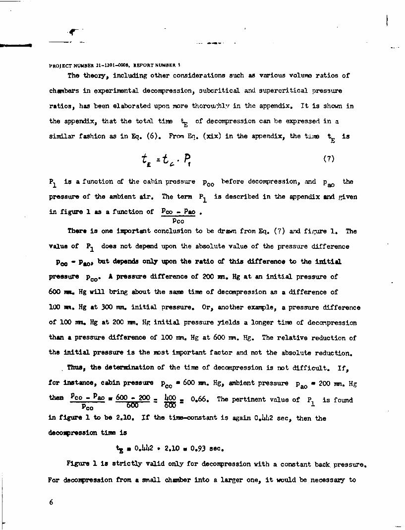
The theory, including other considerations such as various volu'e ratios of
chambers in experimental decompression, subcritical and supercritical pressure
ratios, has been elaborated upon more thoromwhly in the appendix. It is shown in
the appendix, that the total time tE of decompression can be expressed in a
similar fashion as in Eq. (6). From Eq. (xix) in the appendix, the tiie t is
t~ P (7)
P1 is a function of the cabin pressure Pco before decompression, and pao the
pressure of the ambient air. The term P1 is described in the appendix and given
in figure 1 as a function of Pco - Pao.
PcoThere is one important conclusion to be drawn from Eq. (7) and figure 1. The
value of P1 does not depend upon the absolute value of the pressure difference
Po - Pao, but depends only upon the ratio of this difference to the initial
pressure Pco" A pressure difference of 200 mm. Hg at an initial pressure of
600 mi. Hg will bring about the same time of decompression as a difference of
100 m. Hg at 300 mm. initial pressure. Or, another example, a pressure difference
of 100 nu. Hg at 200 am. Hg initial pressure yields a longer time of decompression
than a pressure difference of 100 mm. Hg at 600 m. Hg. The relative reduction of
the initial pressure is the mst important factor and not the absolute reduction.
Thus, the determination of the time of decompression is not difficult. If,
for instance, cabin pressure pc0 m 600 m. Hg, ambient pressure pao a 200 mm. Hg
then Pco - Pao a 600 - 200 = 4o . 0.66. The pertinent value of P is found
PC 3M 1
in figure 1 to be 2.10. If the time-constant is again 0.4h2 sec, then the
decompression time is
* 0.a442 - 2.10 s 0.93 sec.
Figure 1 is strictly valid only for decompression with a constant back pressure.
For decompression from a small chamber into a larger one, it would be necessary to
6
PROJECT NUMBER 21-1201-00oS, REPORT NUMBER
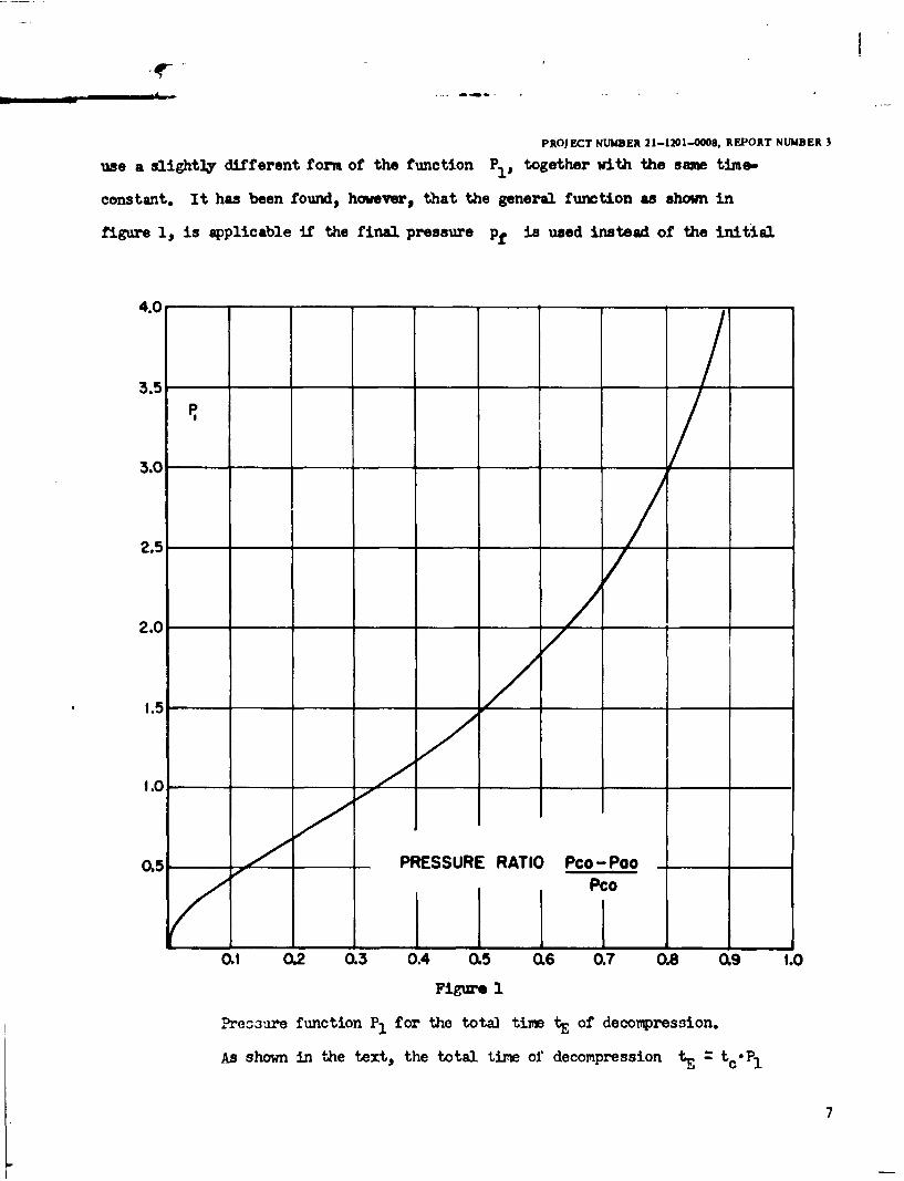
use a slightly different form of the function Pi, together with the saw time.
constant. It has been found, however, that the general function as shown in
figure 1, is applicable if the final pressure pf is used instead of the initial
4.0
3.5
3.0
2.5 /
2.0 _
1.5
1.0
0.5 PRESSURE RATIO Pco- Poo
FPco
Oa1 0.2 0.3 0.4 0.5 0.6 0.7 0.8 0.9 1.0Figure 1
Pret3ure function P1 for the tota] time tE of decompression.
As shown in the text, the total time of decompression tE - tc-PI
7
PROJECT NUMBER 21-1201-000,. REPORT NUMBER 3
pressure Pao. The final pressure pf is the pressure in both chmbers after
decompression and can easily be determined from the gas law to be
N V6 V4 (8)
if Va is the volume of the larger chamber and V. the volume of the smaller
one. The pressure difference to be used in figure 1 is then Pco - Pf instead of
Pco - Pao and is given by
a (PC. - N. Va.V (9)
FQr all practical purposes this substitution is satisfactory trith sufficient accuracy.
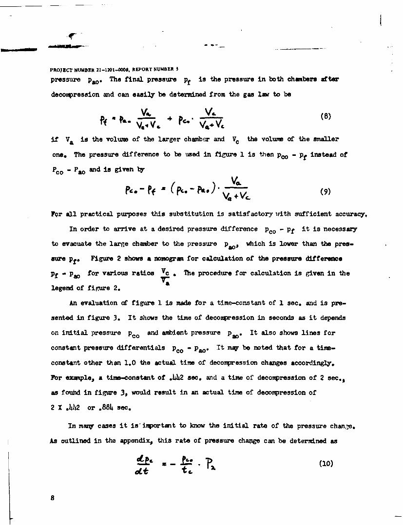
In order to arrive at a desired pressure difference pco - Pf it is necessary
to evacuate the large chamber to the pressure pao$ which is lower than the pres-
sure Pf. Figure 2 shows a nomogram for calculation of the pressure difference
Pf - Pao for various ratios Vc . The procedure for calculation is given in the
legend of figure 2. a
An evaluation of figure 1 is made for a time-constant of 1 sec. and is pre-
sented in figure 3. It shows the time of decompression in seconds as it depends
on initial pressure Pco and ambient pressure pao. It also shows lines for
constant pressure differentials Pco - Pao. It mq be noted that for a tim-
constant other than 1.0 the actual time of decompression changes accordingly.
For example, a time-constant of W.42 sec. and a time of decompression of 2 sec.,
as fouhd in figure 3, would result in an actual time of decompression of
2 X .42 or .884 sec.
In maz cases it is' inportant to know the initial rate of the pressure change.
As outlined in the appendix, this rate of pressure change can be determined as
8
PROJECT NUMBER 21-1201-COM, REPORT NUMBER 3
DESIRED PRESSURE DIFFERENCE VOLUIE RATIO PRESSURE OIFFERECE
Pc*- Pf VC Pf - Poe
Vamm Hq m me
600 4
5O5500
5000.045 7
400 0.02 -/50
1/40
003 101/30300 -II
004 1/25 -12
005 -1/20 -9
006 -4
0.07 1/15 - Is
006 -4
01 1/10 I" .,I/s Is
I/sl U
7 li 31)
0.15 1/4
0.2 1/5 -25
02 ~
90-. 0.40040
so 05 1/2 4,,
06 45To 07
0560 0. 51
LO '/ILO
sso500
10
40-.
Figure 2'0
Noogrm for the calculation of the pressure difference pf -Pao"
Example:The desired final pressure difference is p^- * 200 m. Hg.The volume ratio is 0.25 or By drawing aline from 200 on :,5o
the left scale to 0.25 on the middle scale a pressure differeneof 50 m. Hg is found on the right scale. Therefore a rise inback pressure of 50 mn. Hg is to be expected and an initial L 2oopressure difference Pco - Pa a 200+ 50 a 250 m. Hs would bechosen.
9
PROJECT NUWER 21-1 201-0004, REPORT NUMBER
Eq. (10) shows that the initial pressure pco and the tine-constant t. are the
determining factors for the initial rate of pressure c"aio. The term P2 iz
again a function of the pressure difference Pco - Pao and is shown in figure 4.Pco
In the supercritical range, the tern P2 becomes constant becaise tbe szeed in
the orifice does not increase if the press-re ratio is increased. The determina-
tion of the rate of pressure change with the help of figure 4 is done in the
following fashion: Assuming an initial pressure of nco - 600 mr.I Hg, ambient
pressure 200, then Pco - Pao = 0.66. From figure 4 P2 is fornd tc le 0.69.P 0
With a time-constant of 10. 42 sec. 1he initi.l rate of press-ie clange is
Sc Po.- 50mm Hg
40 IgP.P.40mt
tc -10 sec.
,! "3 0 150 ...
200
200
100 200 3 400 500 600 700 800Pc. mm
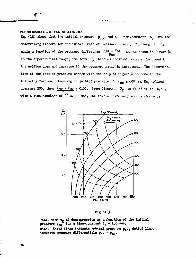
Figure3
Total time It. of decompression as a f unction of the initialPressure Pco for a time-contant t c a 1.0 sec,
Notet Solid lines indicate ambient press-re Pao; dotted linesindicate pressure differentials pco " Pao.
10
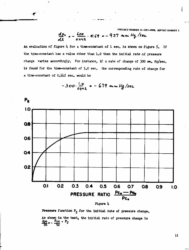
PROJECT NUMBER 21-1201-.O0, REPORT NUMBER 3X_ . _C oo . . ,-93 "," k i ec.
ct o.442
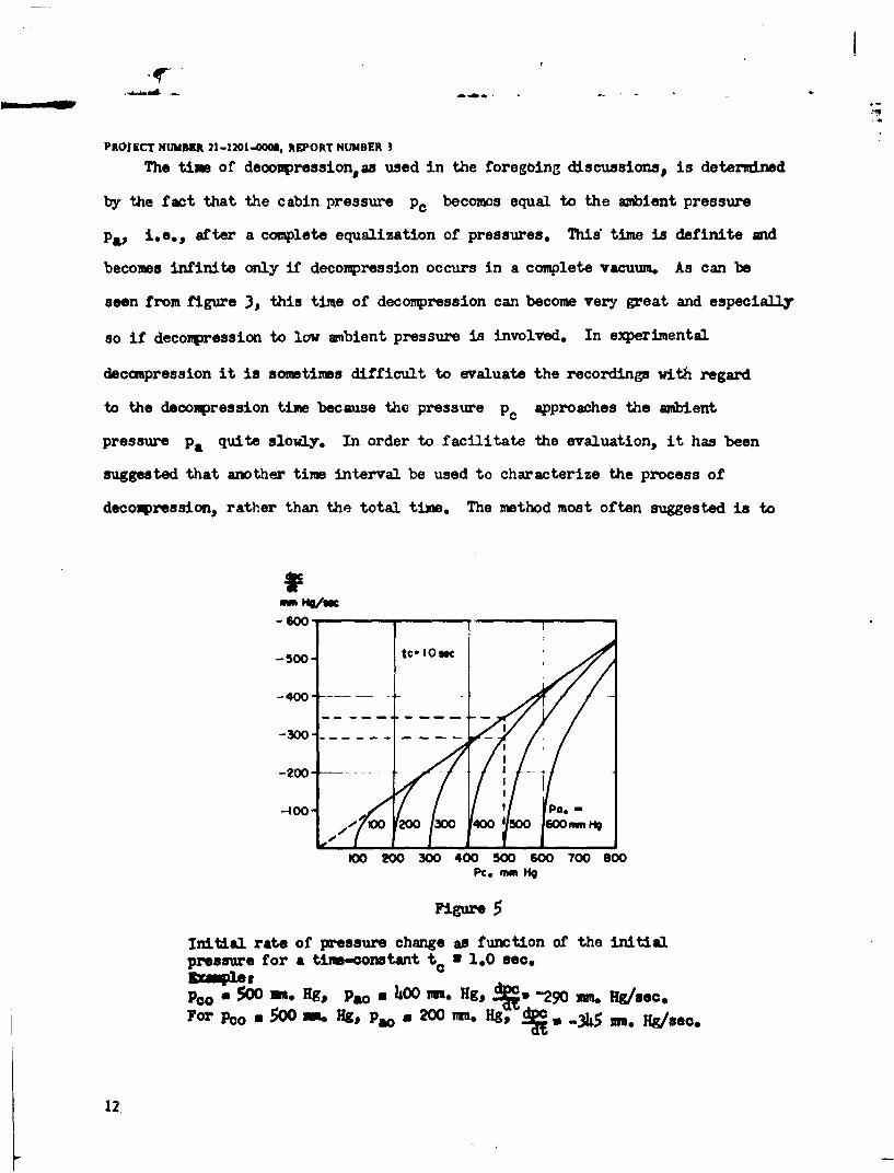
An evaluation of figure 4 for a time-constant of 1 sec. is shown on figure 5. If
the time-constant has a value other than 1.0 then the initial rate of pressure
change varies accordingly. For instance, if a rate of change of 300 m. Hg/sec.
is found for the time-constant of 1.0 sec. the corresponding rate of change for
a time-constant of 0,442 sec. would be
- 3oo. 7'oU .kjI.C.
Pa
18
0.6
04/,
02
0.1 0.2 0.3 0.4 0.5 0.6 0.7 0.8 0.9 1.0
PRESSURE RATIO PC* - PooPc*
Figure 4
Pressure function P2 for the initial rate of pressure change.
As shown in the text, the initial rate of pressure change is
11
-!
PROJECT NUMBER 21-1201-000, REPORT NUMBER 3
The time of deompressionas used in the foregoing discussions, is determined
by the fact that the cabin pressure p. becomes equal to the ambient pressure
PW i.e., after a complete equalization of pressures. This time is definite and
becomes infinite only if decompression occurs in a complete vacuum. As can be
seen from figure 3, this time of decompression can become very great and especially
so if decompression to low ambient pressure is involved. In experimental
decompression it is sometimes difficult to evaluate the recordings with regard
to the decompression time because the pressure pc approaches the ambient
pressure Pa quite slowly. In order to facilitate the evaluation, it has been
suggested that another time interval be used to characterize the process of
decompression, rather than the total time. The method most often suggested is to
-m me/on-600
-500- to"lOgc
-400 ...
-300-.
-200-..
-400- 1/ P0.-
-100
100 200 300 400 500 600 700 800PC. mm H
Figure 5
initial rate of pressure change as function of the initialpressure for a time-constant t. a 1.0 sec,3mple,Pco a 500 u. Hg, pa le 400 imr. Hg, V -290 s . Hg/sec.For Pco a 500 m. Hg, Pao 200 m. Hg, * -345 .
12
PROJECT NUMiBER 21-1201-,000, REPORT NUMBER 3
measure the time which elapses until the initial pressure difference has been
reduced to a certain fraction of itq initiAl value. The introduction of this
arbitrary fraction, however, is debatable.
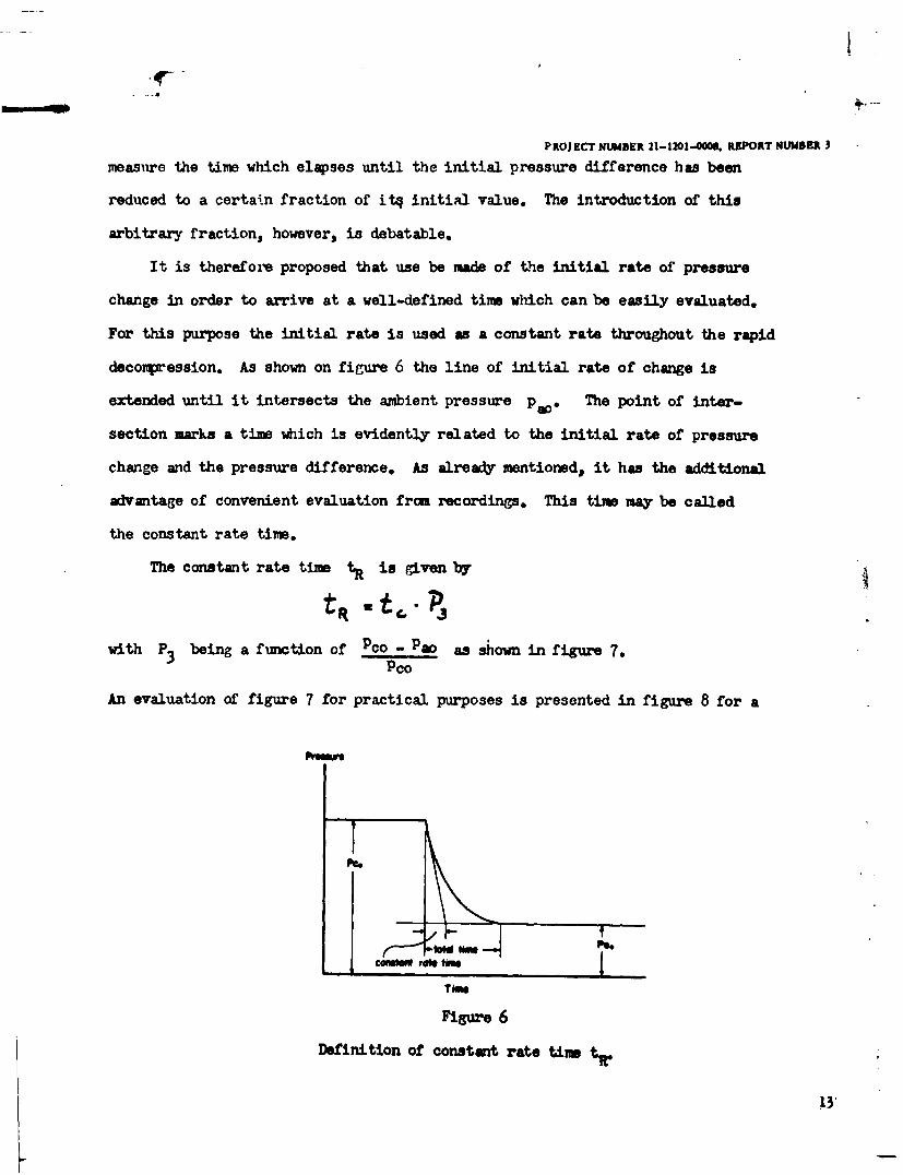
It is therefore proposed that use be made of the initial rate of pressure
change in order to arrive at a well-defined time which can be easily evaluated.
For this purpose the initial rate is used as a constant rate throughout the rapid
decompression. As shown on figure 6 the line of initial rate of change is
extended until it intersects the ambient pressure pa800 The point of inter-
section marks a time which is evidently related to the initial rate of pressure
change and the pressure difference. As already mentioned, it has the additional
advantage of convenient evaluation from recordings. This tim may be called
the constant rate time.
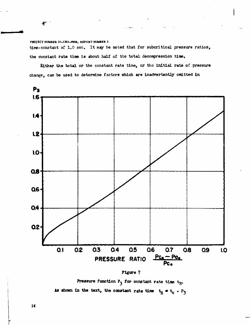
The constant rate time tR is given by
with P3 being a function of Pco Pao as shown in figure 7,Pco
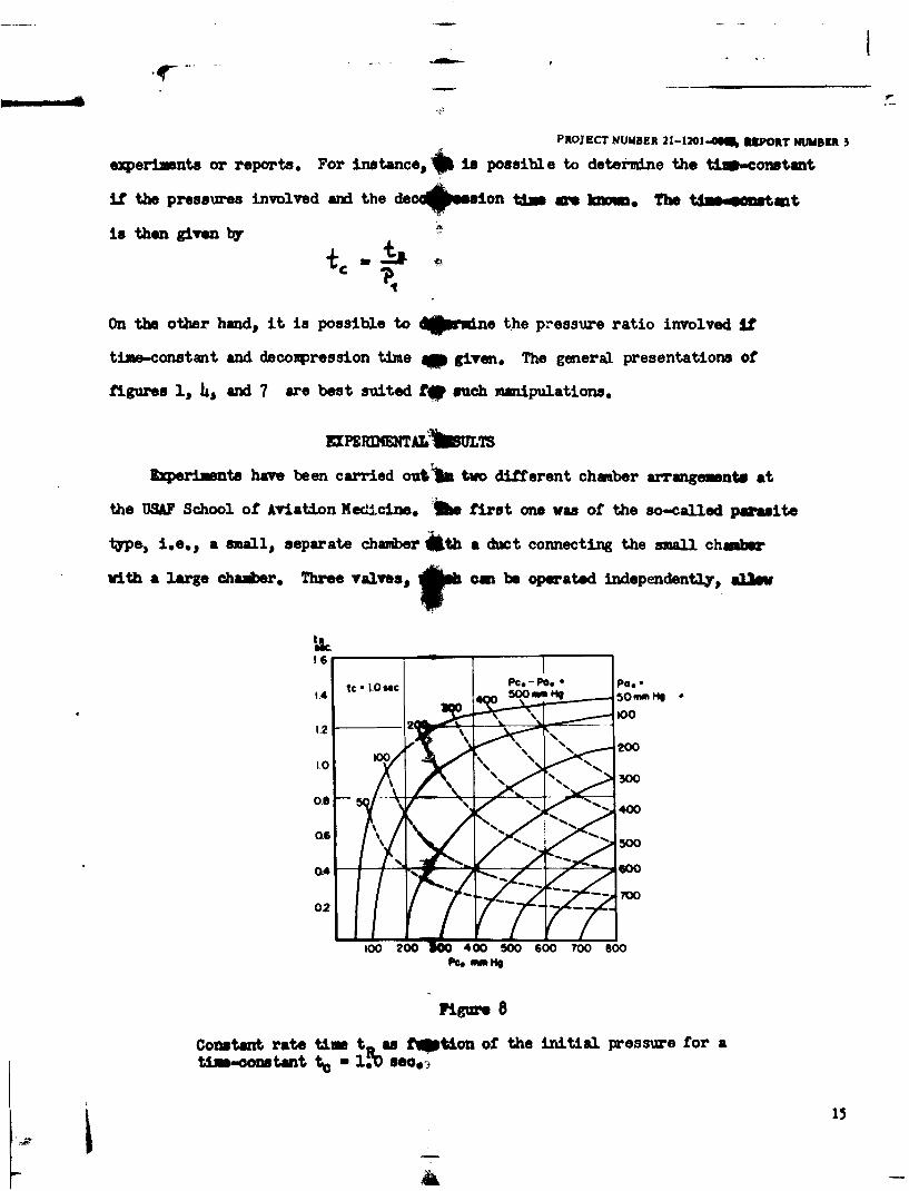
An evaluation of figure 7 for practical purposes is presented in figure 8 for a
Wid fifs
Figure 6
Definition of constant rate time tR.
PROJECT NUMBER 21-1201-000,. REPORT NUMBER 3
time-constant of 1.0 sec. It mor be noted that for subcritical pressure ratios,
the constant rate time is about half of the total decompression time.
ither the total or the constant rate time, or the initial rate of pressure
change, can be used to determine factors which are inadvertentay omitted in
PS1.6,4 -
0.4
0.1 02 0.3 0.4 0.5 Q6 0.7 0.8 09 1.0PRESSURE RATIO Pc.-Poe
PcsFigure 7
Pressure funetion P3 for constant rate time t,
As shown in the text, the constant rate tme S w te P3
14
PROJ ECT NUMBER 21-1214 8 PORT NUMBER 3
ezpoerimnts or reports, For instance,,4 is possible to detei-mine the tiamconstant,
if the pressurwes involved and the decqpuion tin- I" kWW The t8906mstamt
is then given by
On the other hand, it is possible to ,0rine the Pressure ratio involved ILf
time-constant and decompression time qp given, The general presentations of
figures 1, 4, and 7 are best suited t9 such xaipulations.
EXlREXWA;Ib=T
Experiments have been carried out'ju two different chmber arrangementa at
the USAF School of Aviation Medicine, The first one was of the so-called parasite
type,, i,,e., a sfmall, separate chamber *th a duct connecting the small chmbwr
with a large chamber. Three valves,t am be operated independently', allm
160
1.0 0
0020 40 5060 7080
Pc.00
0.6reConsant atetimet ast~ton o th iniial resure4or0
tim-cnsan 500ls~.
LA Goo
PROJECT NUMBER 21-1201-0006, REPORT NUMBER 3
the connection between the two chambers to be opened suddenly. A detailed de-
scription ot' this setup is riven in n separate report (6).
The second chamber arranornent used in the experiments was a high-altitude
chamber with a small air lock. The door from the air lock to the chamber has a
circular opening of U1 inches in diameter. This opening can be sealed off by a
rmbrane which is then rmctured for the rapid decompression. This latter arrange-
ment will be referred to as the D-chanber, in this report.
;!eaurements were taken of the absolute pressure Pc in the small chamber
V. and of the pressure difference pc - pa between the small and the large
chamber. For the pressure recordings Statham strain gages were used with a
pressure range of 15 p.s.i. and a natural frequency of 100 c.p.s. The temperature
chances in the small chamber were recorded with iron-constantan thermocouples.
A very small tim lag of the thermcouple was obtained by the use of a wire with
0.0008.inch *amter. The recordings were made with suitable galvanometers and a
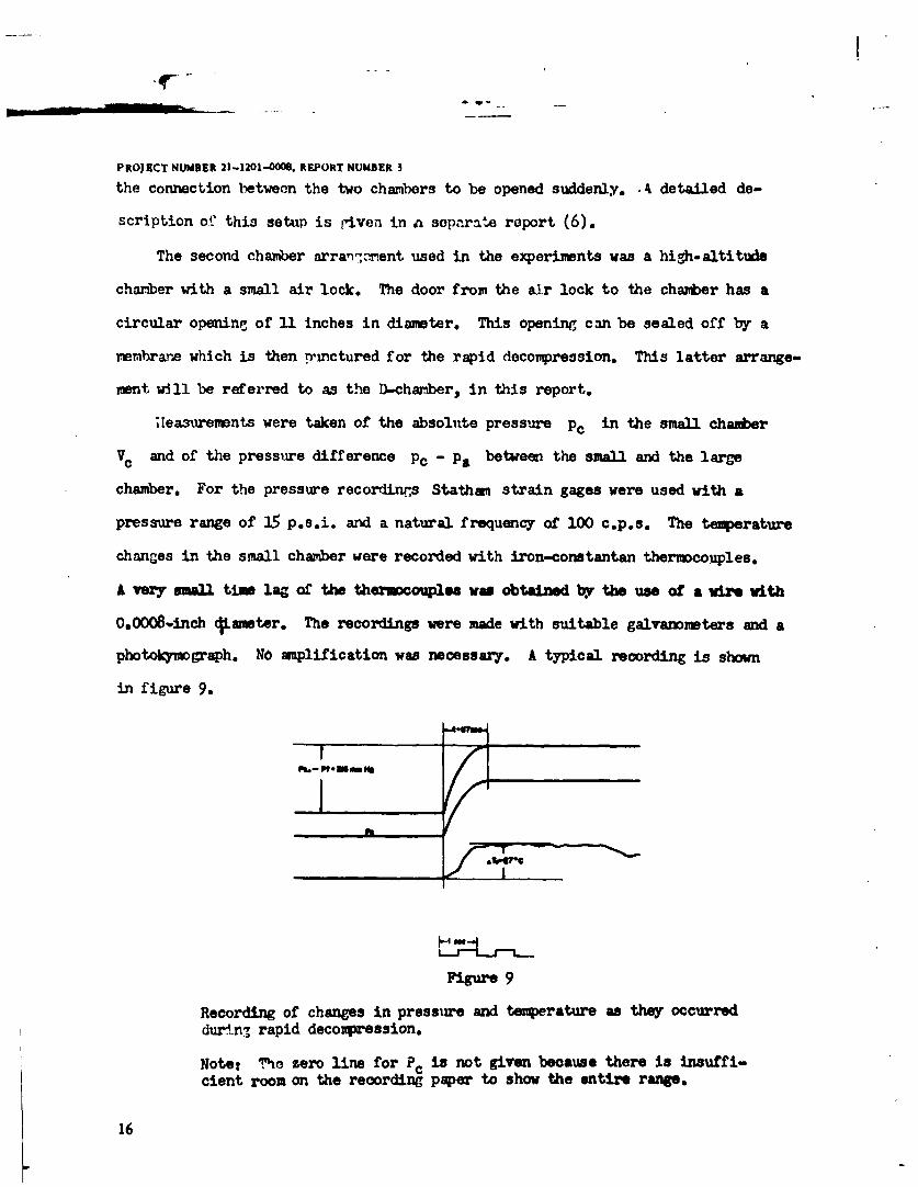
photokymograph. No amplification was necessary. A typical recording is shown
in figure 9.
Figure 9
Recording of changes in pressure and temperature as they occurreddurn. rapid decompression.
Note: The zero line for PC is not given because there is insuffi-cient room on the recording paper to show the entire range.
16
PROJECT NUMBER 21-1201-0o0, REPORT NUMBER 3
In all, about 75 rapid decopressions were recorded over a wide range of
pressures, with various combinations of the aforomentioned valves, in order to
have various time-constants.
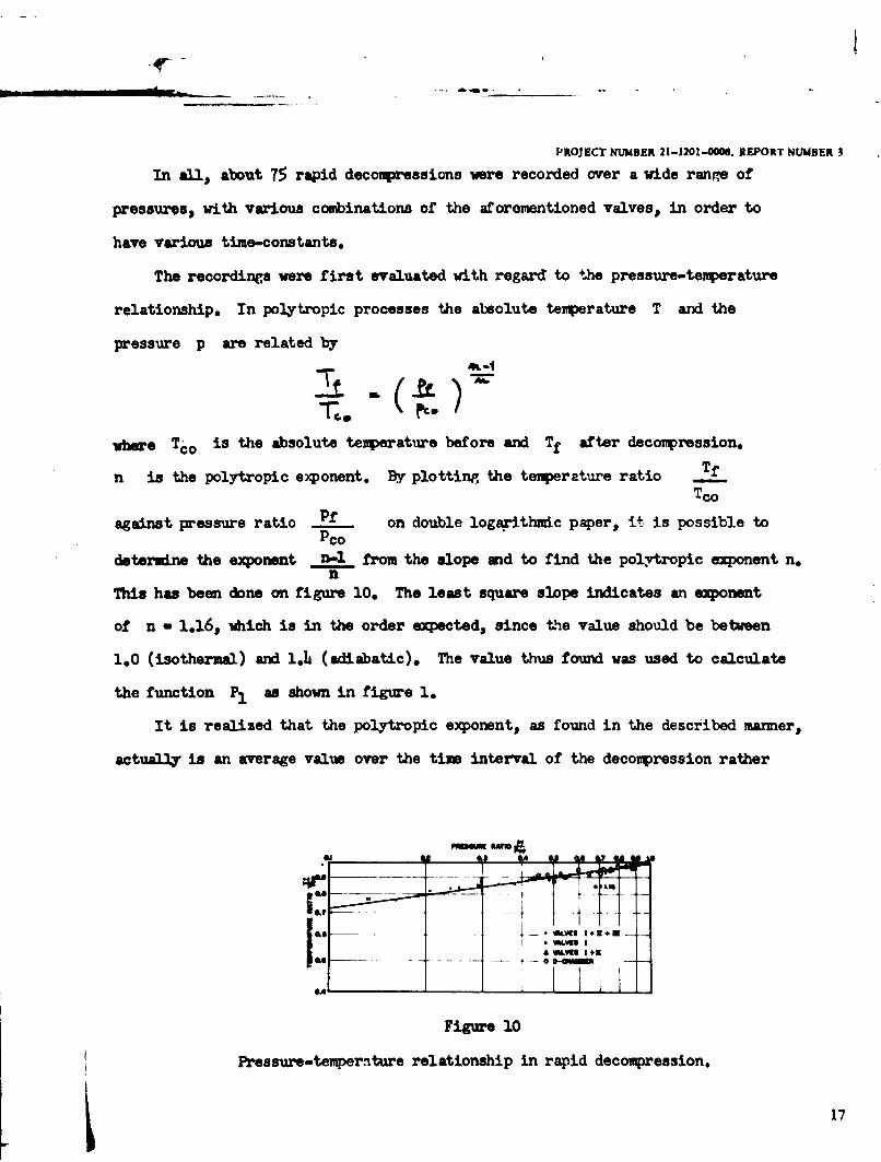
The recordings were first evaluated with regard to the pressure-temperature
relationship, In polytropic processes the absolute temperature T and the
pressure p are related by
where Tco is the absolute temperature before and Tf after decompression.
n is the polytropic exponent. By plotting the temperature ratio Tf
Tco
against pressure ratio P. on double logwairthmdc paper, it is possible toPco
determine the exponent n-1 from the slope and to find the polyvtropic exponent n.n
This has been done on figure 10. The least square slope indicates an exponent
of n - 1.16, which is in the order expected, since the value should be between
1.0 (isotherml) and 1.4 (adiabatic). The value thus found was used to calculate
the function P1 as shown in figure 1.
It is realized that the polytropic exponent, as found in the described manner,
actually is an average value over the time interval of the decompression rather
a MV I +a;
Figure 10
Pressure-temperature relationship in rapid decompression.
17
PROJECT NUMBER 21-1201-0006. REPORT NUMBER 3
than an instantaneous one. However, in this discussion emphasis is on the average
values, which are valid for the rapid decompression as a whole. The value of the
polytropic exponent has an influence on the value of the speed of sound. 14ith
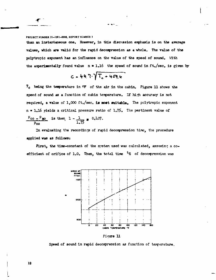
the experimentally found value n I 1.16 the speed of sound in ft./sec. is given by
Tc being the temperature in OF of the air in the cabin. Figure 1 shows the
speed of sound as a function of cabin temperature. If hi.*h accuracy is not
required, a value of 1,000 ft./sec. is et suitable. The polytropic exponent
n a 1.16 yields a critical pressure ratio of 1.75. The pertinent value of
CO - Pao is then 1- 1 o.427.Pco 1.75
In evaluating the recordings of rapid decompression time, the procedure
applied was as followst
First, the time-constant of the system used was calculated, assuming a co-
efficient of orifice of 1.0. Then, the total time tE of decompression was
8009to OF'I, ,,... I I1
100 -
0 to 40 60 so 100 120 140 ISO
CASIN TEPIRATURE *F
Figure 31
Speed of sound in rapid decompression as function of temperature.
18
PROJECT NUMBER 21-1201-0008, REPORT NUMBER 3
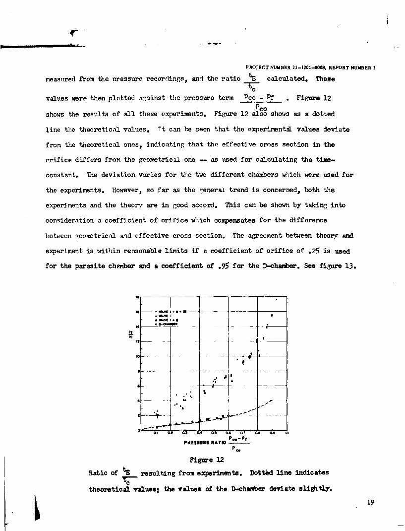
measured from the nressure recorcIings, and the ratio tE calculated. These
cvalues were then plotted a7inst the pressure term Pco - Pf . Figure 12
Pcoshows the results of all these experiments. Figure 12 also shows as a dotted
line the theoretical values. Tt can be seen that the experimental values deviate
from the theoretical ones, indicating that the effective cross section in the
orifice differs from the geometrical one - as used for calculating the time-
constant. The deviation varies for the two different chambers which were used for
the experiments. However, so far as the .-enerai trend is concerned, both the
experiments and the theory are in good accord. This can be shown by takin-, into
consideration a coefficient of orifice which compensates for the difference
between 7eometrical and effective cross section. The agreement between theory mid
experiment is within reasonable limits if a coefficient of orifice of .25 is used
for the parasite chz'ber and a coefficient of .95 for the D-chamber. See figure 13.
'I
WK I*Eaa D-CPAUU
14 - -- - -
4-Th* -1
.. ..
Figure 12
Ratio of tE resulting from experiments. Dott~d line indicatesC
theoretical values; the values of the f-chamber deviate slightl.
19
PROJECT NUMBER 21-1201-0008, REPORT NUMBER 5
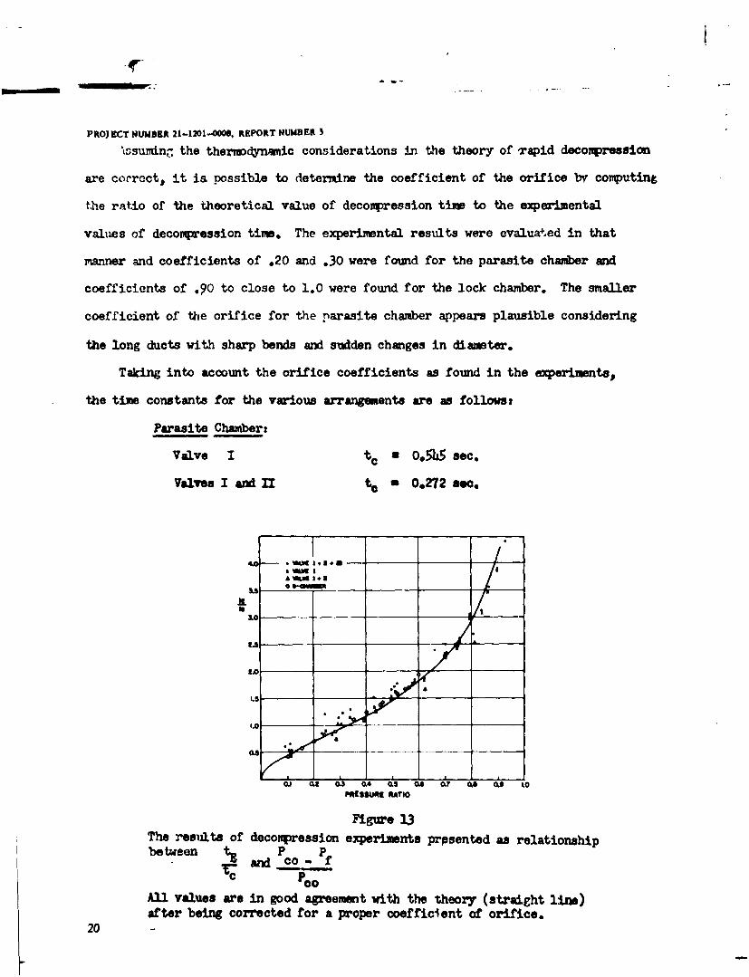
Issunirn. the thermodynamic considerations in the theory of rapid decompression
are correct, it is possible to determine the coefficient of the orifice by computing
Lhe ratio of the theoretical value of decompression tim to the experimental
values of decompression time. The experimental results were evaluated in that
manner and coefficients of .20 and .30 were found for the parasite chamber and
coefficients of .90 to close to 1.0 were found for the lock chamber. The smaller
coefficient of the orifice for the parasite chamber appears plausible considering
the long ducts with sharp bends and sudden changes in diameter.
Taking into account the orifice coefficients as found in the experiments,
the time constants for the various arrangements are as followst
Parasite Chamber:
Valve I t c a 0.55 sec.
Valve I and II t a 0.272 s.c,
La-
,£ W.t I.En
0A1 01 0. A0 0.8 O.6 0-7 as W. 1.O
Figure 13
The results of decompression experiments prpsented as relationshipbetween tz P
T1and CO -fC POO
All values are in good agreement with the theory (straight lie)after being corrected for a proper coefficient of orifice.
20
PROJECT NUMBER 21-1201-0008, REPORT NUMBER3
Valves I, II, and III t c 0.181 sec.
D-Chwabert to 0.712 sec.
It =q be noted that the effective cross section is a point of uncertainty if
it comes to reducing to practice the theory of rapid decompression since it has a
strong influence on the tim-constant. For cases like those occurring in aircraft,
coefficients of 0.8 to 1.0 seem appropriate.
Acknoledgment
The authors wish to express their gratitude to Dr. R. W. Bancroft for his
invaluable help and suggestions.
REINCES
1. Kotoher, 3. Prea mv-tt4 relationship. within a superchargodcabin which has ben punctured, Air Corps Technical RoportNo. 96, 7 Apr. 191a.
2. Sweeney, H.M. Explosive decompression-human subject. MemorandumReport No. Eng. 49-695-29, Army Air Forces Materiel Comuand,Engineering Division, 7 June 1943.
3. Gagge, A.P. Explosive decompression A sunmary and evaluation foraircraft designers. Memorandumn Report No. TSEAL 3-695-297,Arnq Air Forces, Air Technical Service Command, 2 July 1945.
4. Roth, H.P. Studc-decompression time for pressurized cabins.Report No. AE-131-R, AiResearch Manufacturing CompazW,2 Jan. 1945.
5. Haber, F. Physical process of explosive decompression. J. AviationMed. 21: 495 (1950).
6. Clamarnn H.O., and F. Haber. Physics and anginrerinq of rapiddecompression. USAF School of Aviation Medicine project(inpreparation).
21
P RGECT NUMBER 21-1201-000, REPORT NUMBER 3
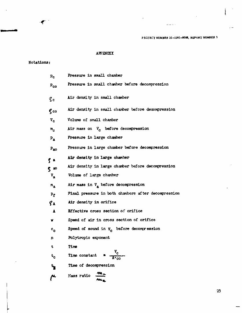
APPIWX
Notations:
PC Pressure in small chamber
Pco Pressure in small chamber before decompression
c Air density in small chamber
1co Air density in small chamber before decompression
Vc Voluxe of small chamber
MC Air mass on Vc before decompression
Pa Pressure in large chamber
Pao Pressure in large chamber before decompression
Air density in large chamber
Air density in large chamber before decompression
Va Volume of large chamber
ma Air mass in Va before decompression
Pf Final pressure in both chambers after decompression
?A Air density in orifice
A Effective cross section of orifice
w Speed of air in cross section of orifice
c o Speed of sound in VC before decompr ession
n Polytropic exponent
t Time
t c Time constant -
t Time of decompression
Mtass ratio -- -.
23
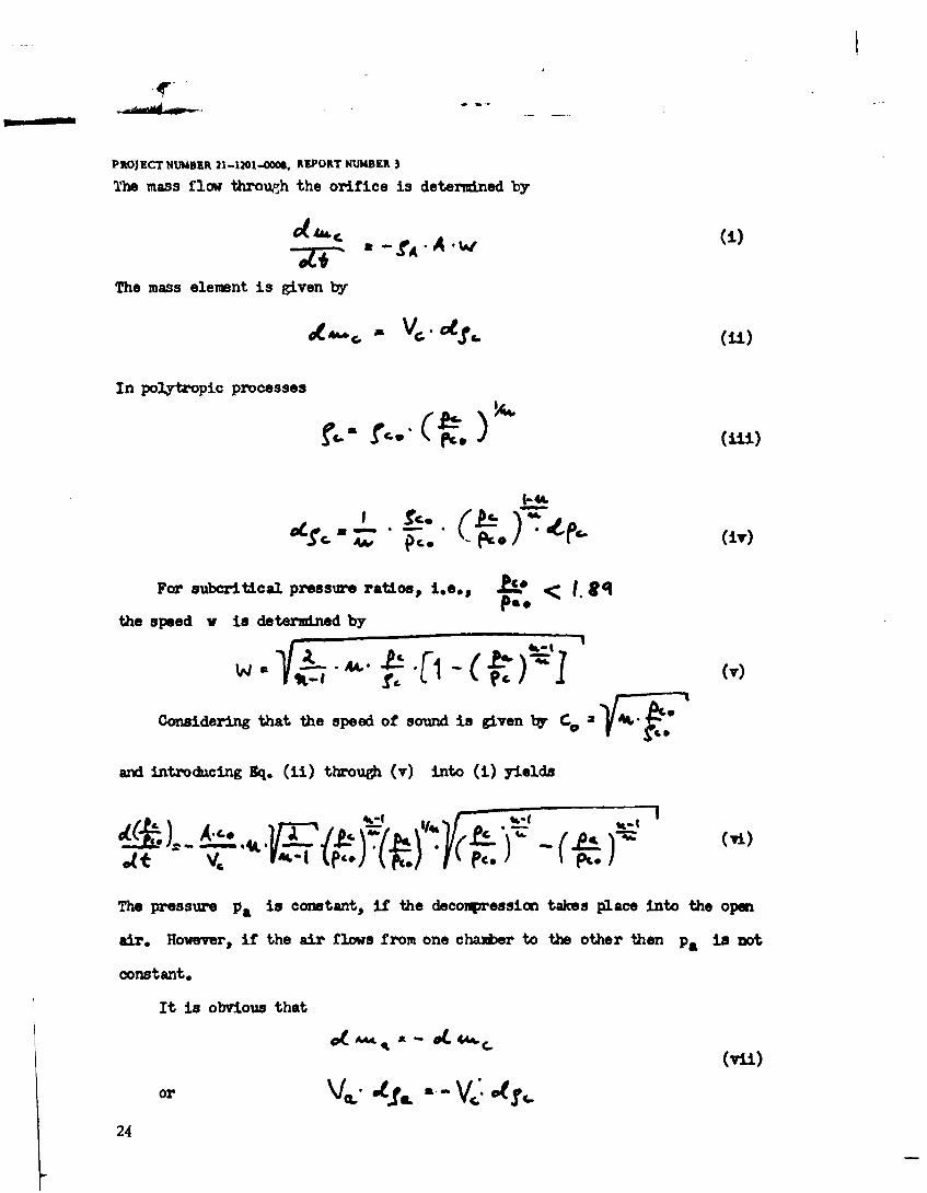
PROJECT NUMBER 21-1201-000S, REPORT NUMBER
The mass flow through the orifice is determined by
(1.a-fA
The mass elemnt is given by
In polytropic processes
For subcritical pressure ratios,, i , p ( , gqpa.the speed w is determined by
SA~ 0- -- ((.,)Considering that the speed of sound is given by f f '
and introdacing Sq. (ii) throuh (v) into (i) yields
The pressure V. is corstant, if the decompression takes place into the open
air. However, if the air flows from one chamer to the other then pa is ot
constant,
It is obvious that
(vii)
or V2 4fL V o
24

PROJECT NUMBER 21-1201-OCOS, REPORT NUMBER 3
Integrating Sq. (vii) and introducing Eq. (iii) results in
9%." W .A: [ - . C(- : ,]
Finll
is obtained. To facilitate integration the following substitution is made
4W-
which is then expanded into a power series. It was found that accurary was
still satisfactory if all term of orders higher than e 2 were omitted. By
this way 3q. (ix) is reduced to
with
am A"
Integration of (x) yields
(Xi)
25
PROJECT NUMBER 21-1201-OOS, REPORT NUMBER 3
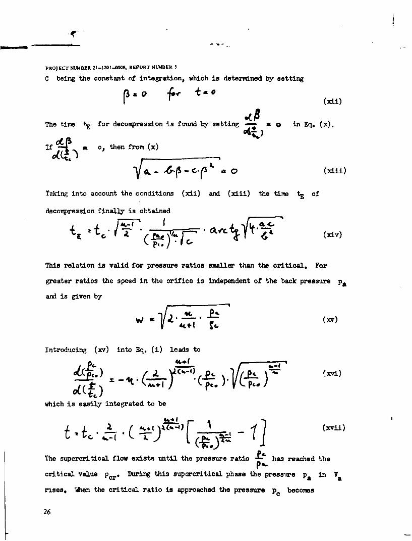
C being the constant of integration, which is determined by setting
P a 01;e -tat)
The time tE for decompression is found by setting -- in Eq. (x).
if a o, then from (x)
-F -- o (xiii)
Tking into account the conditions (xii) and (xiii) the time tF of
decompression finally is obtained
/ t4,.] (Xiv)
This relation is valid for pressure ratios smaller than the critical. For
greater ratios the speed in the orifice is independent of the back pressure pa
and is given by
W (xv)
Introducing (xv) into Eq. (i) leads to
which is easily integrated to be
- * A~.j(4.e) -71](Xvii)
The supercritical flow existn until the pressure ratio - has reached thep..critical value Pcr" During this suprcritical phase the pressure pa in Va
rises. Mien the critical ratio is approached the pressure pc becomes
26
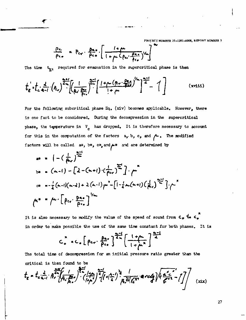
PROJECT NUMBER 21-1201-O08. REPORT NUMBER 3
The time t., required for evacuation in the supercritical phase is then
.. .4 f [ )I4,k / is
4k-1~~ 9K!-(vii
For the following subcritical phase Eq. (xiv) becomes applicable. However, there
is one fact to be considered. During the decompression in the supercritical
phase, the tqmperature in Vc has dropped. It is therefore necessary to account
for this in the computation of the factors a,. b, c, and (-" The modified
factors will be called a*, b*, c*, andi* ard are determined by41-I
SA-,) -U --,( )(#Ir
b*-I n (A.. (4,4) 4(,
e" '"fPC*
It is also necessary to modify the value of the speed of sound from C& o C
in order to make possible the use of the same time constant for both phases. It is
;I1 V < .. A
The total time of decompression for an initial pressure ratio greater than the
critical is then found to be
27
Ar .
PDJCT NMU 31-1201-.000 REFORT NUMBER 3
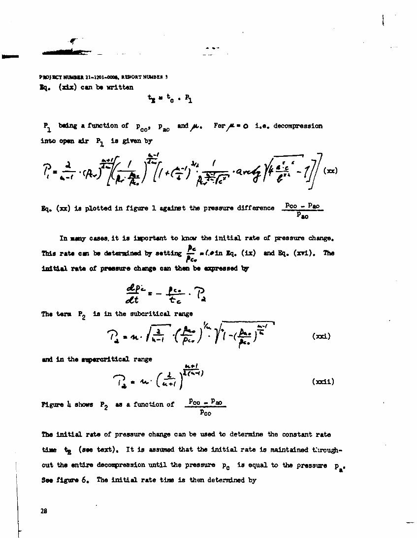
1q. (zi.) can be writtents- to. P1
P1 being a function of p co Pao and For/L 0 i.e. decompression
into open air P1 is given by
Eq. (xx) is plotted in figure 1 against the pressure difference Pco - PaoPao
In my cases, it is important to know the initial rate of pressure change.
This rate cm be determined by setting - a -.in Sq. (ix) and Eq. (xvi). ThePc.
initial rate of pressure change can then be expressed by
The term P2 is in the subcritical range
and in the suprcritical range
Figure 4 shows P2 as a function of Pco -,PaPco
The initial rate of pressure change can be used to determine the constant rate
time t (see text), It is assumed that the initial rate is maintained hrouh-
out the entire decopression until the pressure p0 is equal to the pressure pa"
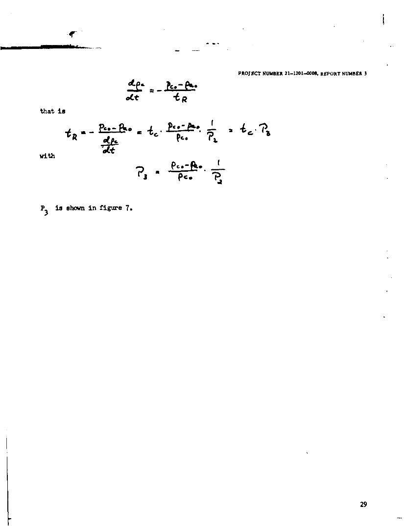
See figure 6. The initial rate time is then determined by
28
PROJECT NUMBER 21-1201-0008, REPORT NUMBER 3
that is
with
P3 is shown in figure 7.
29
DEPARTMENT OF THE AIR FORCEAIR FORCE RESEARCH LABORATORY
BROOKS CITY-BASE TEXAS
4 February 2009
MEMORANDUM FOR DTIC-OCQATTN: LARRY DOWNING8725 JOHN J. KINGMAN ROAD, SUITE 0944FORT BELVOIR, VA 22060-6218
FROM: 711 th HPW/OMA (STINFO)2513 Kennedy CircleBrooks City-Base TX 78235-5116
SUBJECT: Changing the Distribution Statement on a Technical Report
This letter documents the requirement for DTIC to change the distribution statement from "C" to"A" (Approved for public release; distribution is unlimited.) on the following technical report:AD Number AD0020374, XC-SAM, PHYSICS AND ENGINEERING OF RAPIDDECOMPRESSION: A GENERAL THEORY OF RAPID DECOMPRESSION.
If additional infomation or a corrected cover page and SF Fomr 298 are required please let meknow. You can reach me at DSN 240-6019 or my e-mail address issherrv.mathewsa,brooks.a f.m i I.
Thank you for your assistance in making this change.
SHERRY "Y. MATHEWS
7 1 1 h HPW STINFO OfficerPreviously AFIOH STINFO Officer