Embed Size (px)
Citation preview
UNCLASSIFIED
AD NUMBER
LIMITATION CHANGESTO:
FROM:
AUTHORITY
THIS PAGE IS UNCLASSIFIED
AD007460
Approved for public release; distribution isunlimited.
Distribution authorized to DoD only;Administrative/Operational Use; DEC 1952. Otherrequests shall be referred to Naval OrdnanceLaboratory, White Oak, MD. Pre-dates formal DoDdistribution statements. Treat as DoD only.
NOL ltr dtd 29 Aug 1974
UNCLASSIFIED
AD
DEFENSE DOCUMENTATION CENTER FOR
SCIENTIFIC AND TECHNICAL INFORMATION
CAMERON STATION ALEXANDRIA VIRGINIA
DOWHGRADED AT 3 TOAR INTERVALS: DECLASSIFIED ATTER 12 YEARS
DOD DIR 520010
UNCLASSIFIED

THIS REPORT HAS BEEN DECLASSIFIED AND CLEARED FOR PUBLIC RELEASE.
DISTRIBUTION A APPROVED FOR PUBLIC RELEASE;
DISTRIBUTION UNLIMITED.

8 fa—m
C3 CO
NAVORD REPORT 242 51
A SYSTEMATIC STUDY OF A VARIABLE AREA
DIFFUSER FOR SUPERSONIC WIND TUNNELS
December 1952
U. S. NAVAL ORDNANCE LABORATORY WHITE OAK, MARYLAND
ja
CNCLASSIFSSli NAVOED Report 2421
A SYSTEMATIC STUDY OF A YAK, SABLE AREA :UfffUiiAii tun ouriiAauiiiVi >'IHU I unnsitr
Prepared by:
J. L. Dlifgias and A. H. Lange
ABSTRACT: A diffuse? of variable geometric shape was tested for pressure recovery at Mach numbers 1.9, 2.5, 2.8; and 4.8 in tb» continuous NOL 18 x 18 cm Aerophysics °?unnel No, 3. The diffuser consisted of a ecnvsrging- diverging, two-dimensional, variable-area duct. The opening of the diffuser throat and the location of the throat along the center line of ~ih© duet was varied systematically during the tests. Furthermore, the effect of closed or half open test section on diffuser efficiency and that of a model in the air stream sere investigated.
Operating and starting pressure ratios of the wind tunnel sere determined and performance data of the diffuser are given for both cases. Pressure recoveries of the operating tunnel sere obtained for optimum diffuser configurations with diffuser end-pressure ranging up to 1.8 times pitot pressure in the test section at E * 4.9. Also lover pressure ratios to start the tunnel than previously known sere found. This means that, using this diffuser, a continuous tunnel can now fc<% operated with less power, or an intermittent tunnel can run for a longer time, and that the? both can be started with a smaller (closer to one) over-all pressure ratio.
The pressure recoveries obtained in a half open test section and with models in the stream are somewhat lower, but the performance of the diffuser is not seriously offset by those modifications.
U. S. NAVAL CRBNAKCE LABORATORY SHITE' OAK, MARYLAND
•-

r 1
Figure
Figure Figure
2 3
Figure Figure
4 5
Figure 6
Figure 7
Figure 8
Figure 9
Figure 10
Figure li
Figure •» *?
Figure 13
Figure 14
Figure 15
UNCLASSIFIED NAVORD Report 2421
ILLUSTRATIONS
Page NOL 18 z 18 ce Aerophysica Wind Tunnel 10 Diffuser Hinge 11 Diffuser Zntrance and Duct Modifications 12 Duct Configuration, Schematic ... 13 Pressure Recovery for Optlsua Diffuser Throat Location. M = 1.88 . 14 Pressure Recovery for Optlsua Diffuser Throat Location. M = 2.48 . 15 Pressure Recovery for Optlsua Diffuser Throat Location. M - 2.83 . 16 Pressure Recovery for Optlsua Diffuser Tujroat Location. M • 4.92 . 17 Optlsua Pressure Recovery (Pitot Press. Ratio) as a Function cf Throat Location 18 Opti*uB Pressure Recovery (Supply Press, Ratio) as a Function of Throat Location 19 Diffuser Throat opening A**/A vs. Uach Nuaber for Start ana Operation. 20 Starting Pressure Rstio vs. Diffuser area Ratio for Optiaua Diffuser Throat Locations 21 Comparison of Diffuser Recoveries Referred to Supply and Pitot Pressure 22 Ccaparison of Starting Pressures Referred to Static and Pitot Pressure 23 Flow Breakdown in the Diffuser Throat, M - 1.86 24
•
iv UNCLASSIFIED
L A

r a
TJNCLASSIFIBD
NAVOFD Report 2*?,\ December 1952
This NAVORD discusses a systematic study of m high efficiency dlffuser for a acjerzoaic wind tu&nel. Zt WAS decided in 1946 •<* build a new version of the NOL 18 x 18 cm continuous wind tunnel. Dr. H. B. Kursweg initiated the derign of an improved diffuse? as a part of this project. The first results or* pressure recovery were published in 1949 an<* the efficiency attained was higher than that of previous diflusers. Mr. J. L. Dlgglns then carried out a systems.tic study on optimum dlffuser configuration in a range of Mach numbers. Before completion of thir work Mr. Diggins trans- ferred fro* WOL and Mr. A B. Lange completed the investigation and therefore reports the data.
The authors wish to acknowledge the work of Mr. R. W. Henderson who designed the complex dlffuser mechanism.
EDWARD L. VOODTARD Captain, USK Commander
H. II. KURZWEo, Chief Aeroballlstlc Research Department Br direction
» il
UNCLASSIFIED
I
1
UNCLASSIFIED NAVORD Report 2421
CONTENTS
Page I. INTRODUCTION 1
II. TEST EQUIPMENT 2
III. TEST PROCEDURE 2
IV. RESULTS 3
V. CONCLUSION 7
VI. REFERENCES 8
iii UNCLASSIFIED
• •-'
J

1 UNCLASSIFIED
NAVORD Report 2421
1
Figure 2 figure 3
Figure 4 Figure 5
Figure 6
Figure 7
Figure 8
•
: Figure 9
•
i Figure 10
*
Figure 11 :
Figure 12
Figure 13
Figure 14
Figure 15
ILLUSTRATIONS
Page NOL 18 x IS ca Aerophysics Wind Tunnel 10 niffuser Hinge 11 Diffuser Entrance and Duct Modifications. 12 Duct Configuration, Schematic ... 13 Preaaure Recovery for Optiaua Dtrfuaer Throat Location. M = l.GG . 14 Pressure Recovery for Optinus Dlffusar Throat Location. M - 2.48 . IS Pressure Recovery for Optimum Diffuser Throat Location. M - 2.83 . 16 Pressure Recovery for Optimum Diffuser Throat Location. M . 4.92 . 17 OptiBUB Pressure Recovery (Pitot Press Ratio) as a Function of Throat Location . 18 Optimum Pressure Recovery (Supply Press. Ratio) as a Function of Throat Location 19 Diffuser Throat Opening A**/A vs. Mach Number for Start and Operation. 20 Starting Pressure Ratio vs. Diffuser Area Ratio for OptiBus Diffuser Throat Locations 21 Coaparison of Diffuser Recoveries Referred to Supply and Pitot Pressure 22 Coaparison of Starting Pressures Referred to Static and Pitot Pressure 23 Flow Breakdown in the Dlffusar Throat, M - 1,86 24
lv UNCLASSIFIED
I
L
UNCLASSIFIED NAVORD P.eport 2421
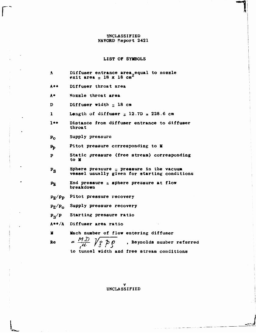
LIST OF SYMBOLS
A Diffuser entrance area equal to nozzle exit area = 18 x 18 cm2
A** Diffuser throat area
A* Nozzle throat area
D Diffuser width = 18 en
1 Length of diffuser - 12.7D = 228.6 en
1** Distance from diffuser entrance to diffuser throat
p0 Supply pressure
p_ Pltot pressure corresponding to M
p Static pressure (free strean) corresponding to M
p Sphere pressure - pressure In the vacuum vessel usually given for starting conditions
pg End pressure = sphere pressure at flow breakdown
pE/pp Pltot pressure recovery
Pfc/p0 Supply pressure recovery
Ps/P Starting pressure ratio
A»*/A Diffuser area ratio
H Hach number of flow entering diffuser
Re = ——— 1/<* 7> t) , Reynolds number referred
to tunnel width and free stream conditions
v UNCLASSIFIED
1

UNCLASSIFIED fJAVORD Report 2421
A SYSTEMATIC STUDY OF A VARIABLE AREA DIFFUSER FOK SUPERSONIC WIND TUNNELS
I. INTRODUCTION
1. Until 1946, diffusers In supersonic wind tunnels were generally shaped following a design given by Prasdti in 1926 for the small 6 x 6 CUB Goettinges tunnel (reference 1) or simple diverging ducts were employed as in subsonic tunnels. Prandti's variable area diffuser, horrever, was mainly meant to be a device to keep the flow steady and independent of the pressure in the vacuum vessel over the blow-down period of intermittent wind tunnels and Irreversi- bilities in the flow were of little concern at that time. Later, the high power requirement of larger tunnels directed the attention to the more efficient transformation of the kinetic energy contained in the flow into pressure by the use of better diffusers, in 1944, Oswatitsch (reference 2) demonstrated experimental- ly for a ramjet diffuser that pressure recoveries higher than those attained by a normal shock and subsequent isentrcpic deceleration (pitot recovery) could be obtained when the fluid was made to pass through & number of oblique shocks. The application of these results to the design of wind-tunnel diffusers was initiated at NOL by Kurzweg (reference 3) in 1946, Under his direction, subsequently, a "wedge" diffuser was designed and incorporated in 1949 (reference 4) as part of the NOL Aerophysics Tunnel No. 3. The first above pitot recovery diffuser end pressure was demon- strated by Kurzweg at H » 2.48 (reference 5). In the following, the detailed results obtained from this diffuser are reported. Minimus pressure ratios necessary for starting the tunnel were also determined because the minimum pressure ratio that must be produced by a pump strongly influences its size, cost, and the total cost of a wind-tunnel installation. The final data will be compared with other higher efficiency diffusers such as these given by Neumann and Lustwerk (references 6 and 7) r \d others (references 8, 9, ant'. 10).
1 UNCLASSIFIED
j 1 l i I!
u.

UNCLASSIFIED NAVCRD Report 2421
II. TEST EQUIPMENT
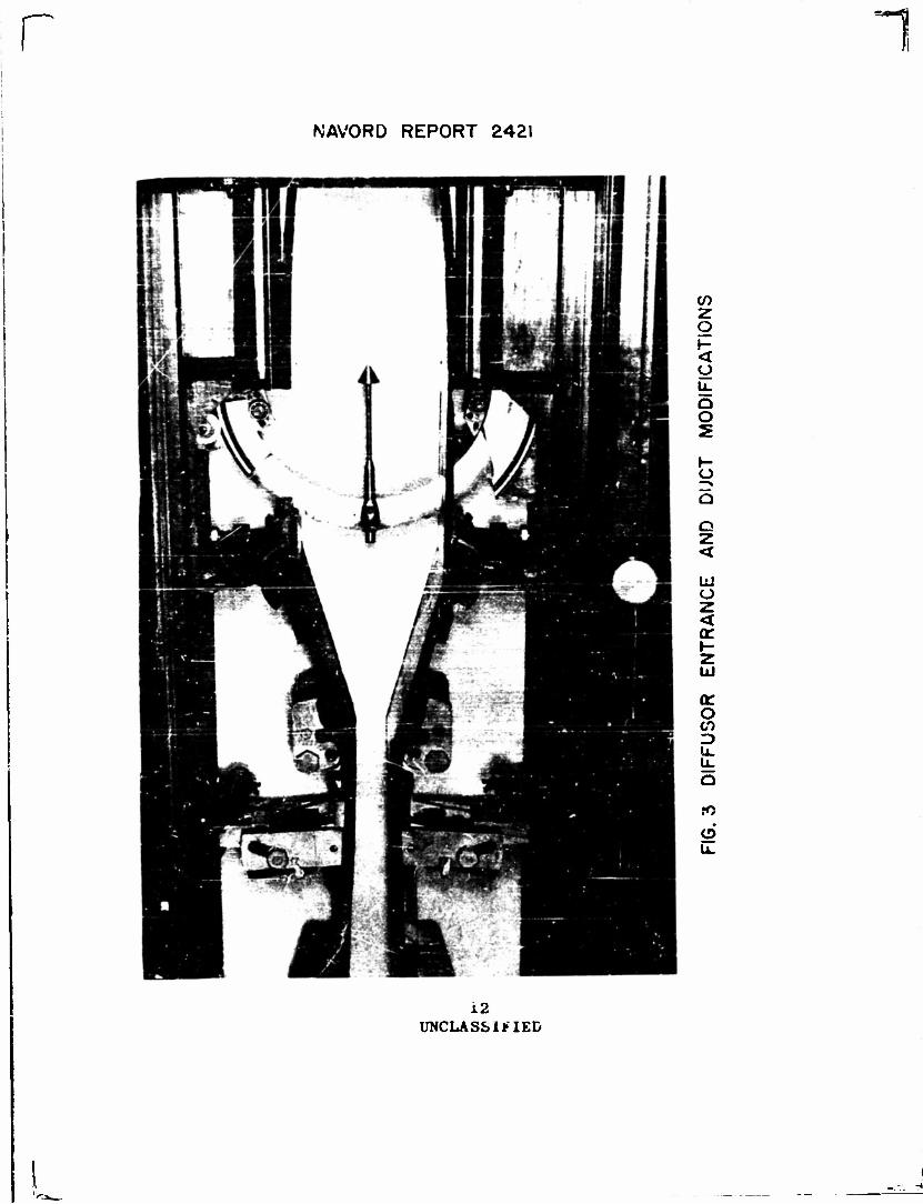
2, A description of the NOL Aerophysics Tunnel No. 3, and particularly the elaborate diffuser mechanism, is given in reference 4. The tunnel (see Figure 1) has an 18 x 18 cm cross-section and parallel sidew&lls. The test section Sfaefr number is changed by inserting various noEsle blocks. The dried supply air has atmospheric temperature and pressure. The air is taken from the atmosphere through drier and tunnel into the vacuum vessel called "sphere." This vessel is evacuated by a set of vacuum pumps sufficiently large to permit continuous tunuel operation. (The sphere is needed for larger tunnels operated inter- mittently by the same plant.) The diffuser is 228.6 cm or 12.7 D long. It consists of two pairs of plane hinged plates which are held between the parallel sidew&lls. These plates form a convergent- divergent duct with the diffuser throat, at the hinge, The front plat? and the rear plate of a pair of hinges (Figure 2) are connected, with the edge of the rear plate having a 6,4 cm radius. The throat can be set at various locations between 0.7 D and 11.7 D down- stream from the diffuser entrance and can be opened or closed during the bio* by ?n electric drive. The axial distance between nozzle exit and diffuser entrance is 25 cm or 1.4 D. With two parallel plates connecting diffuser entrance with nozzle exit, the test section arrangement is called "closed tunnel." With these plates removed the arrangement is called "half-open tunnel." The model us«d in some tests is a 60° total angle cone of 3 cm base diameter on % circular aspc support with a total projected area of 8.7 cm2 or 0.027 A. Figure 3 shows the model io. the tunnel and the top plate removed.
III. TEST PSOCEDCE*
The tost procedure is as follows:
a. Establish a vacuum in the sphere considerably higher than needed for starting the tunnel.
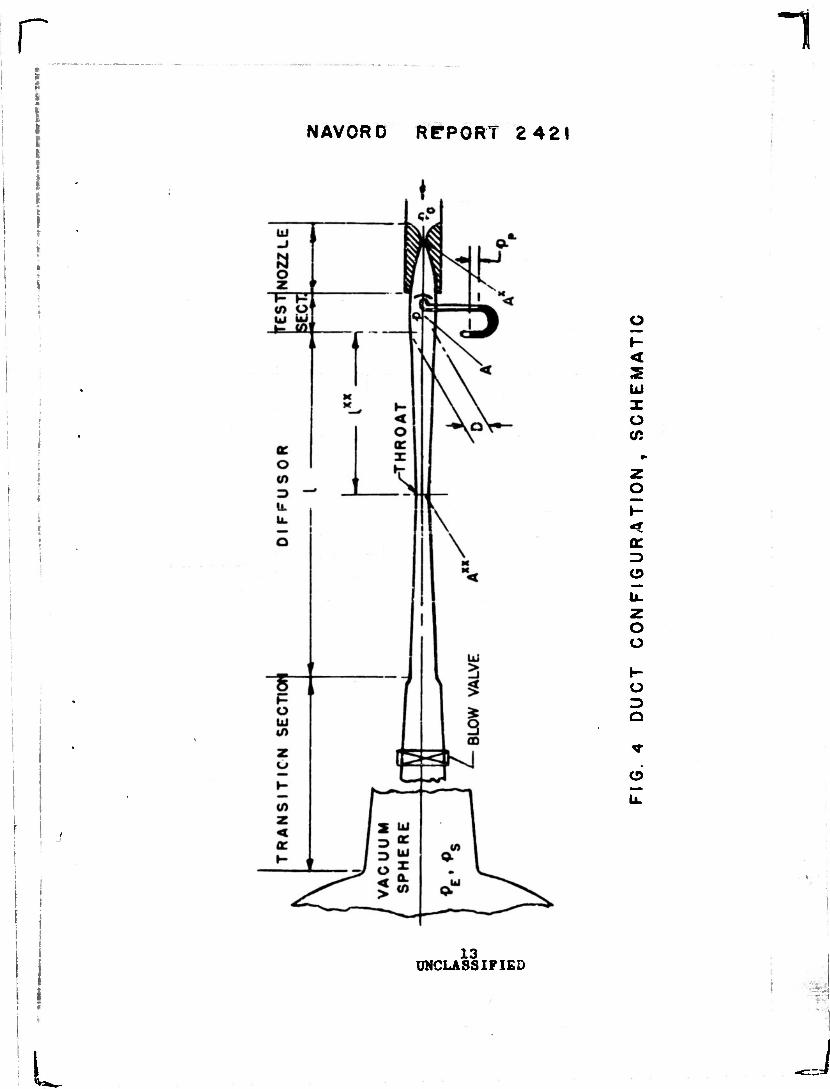
b. Opep valve between tunnel and sphere (blow valve, Figure 4) while having diffuser throat
2 UNCLASSIFIED
* r
•y.<
J
1 !
UNCLASSIFIED NAVORD Report 2421
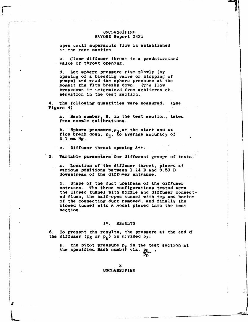
!open until supersonic flow is established in the test section.
c. Close diffuses* throat to a predetermined •slue of throat opening.
d. Let sphere pressure rise slowly (by opening of a bleeding valve or stopping of pumps) and read the sphere pressure at the moment the flow breaks do-vn. (The flow breakdown is determined from schlieren ob- servation in the test section.
4. The following quantities were measured. (See Figure 4)
a. Mach number, II, in the test section, taken from nozzle calibrations.
b. Sphere pressure,oo,at the start and at flow break down, p£, to average accuracy of 0.1 mm Hg. '
c. Diffuser throat opening A**.
5. Variable parameters for different groups of tests.
a. Location of the diffuser throat, placed at various positions between 1.14 D and 9.53 D downstream of the diffu*er entrance.
i b. Shape of the duct upstream of the diffuser entrance. The three configurations tested were the closed tunnel with nozzle and diffuser connect- ed flush, the half-open tunnel with top and bottom of the connecting duct removed, and finally the closed tunnel with a .•nodel placed into the test section.
i : 1 IV. RESULTS
6. To present tho results, the pressure at the end cf the diffuser (ps or p£) is divided by:
a. the pi tot pressure ;pp in the test section at the specified Mach number viz. pg ,
Pp
i 3 UNC?<ASSJFIED
L
r UNCLASSIFIED
NAVORD Report 2421
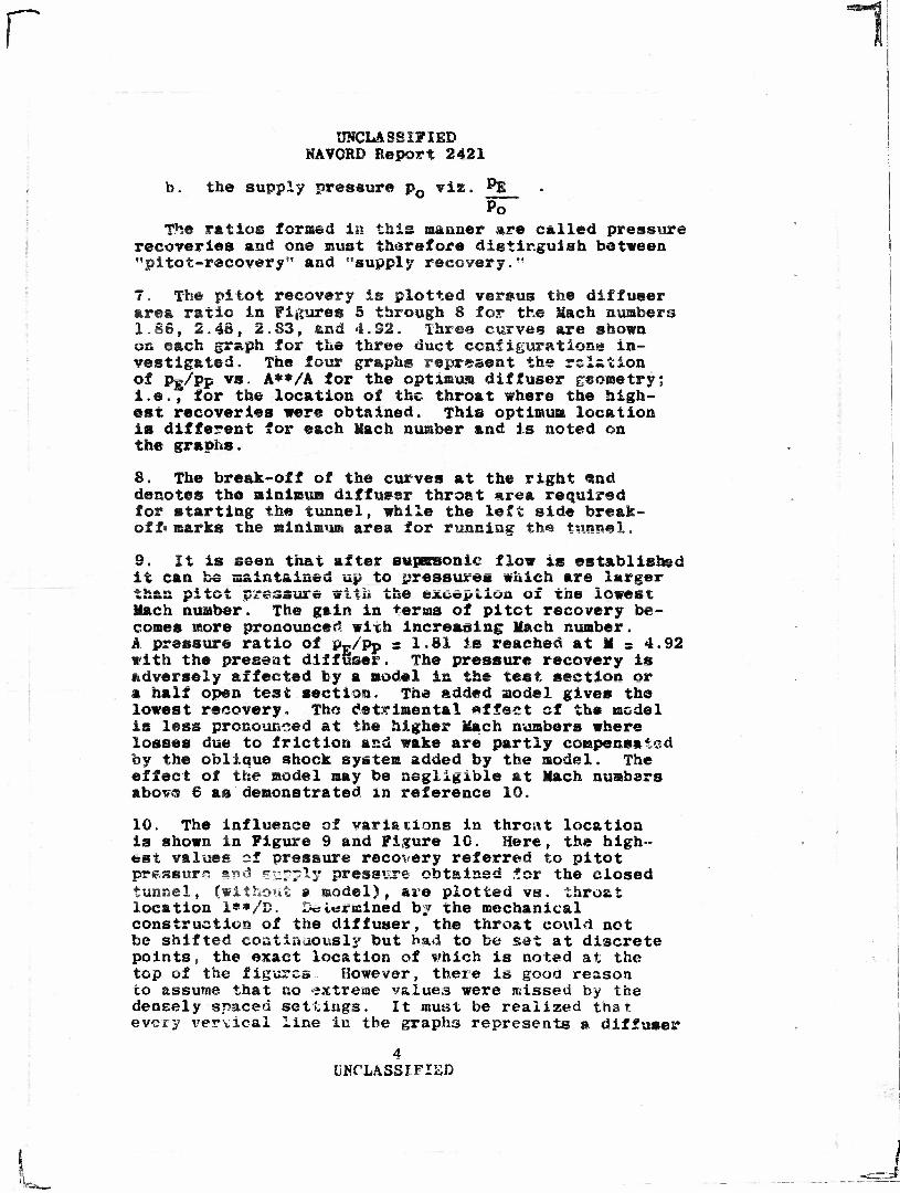
b. the supply pressure pQ viz. PE - Po
The ratios formed In this manner are called pressure recoveries and one must therefore distinguish between "pltot-recovery" and "supply recovery."
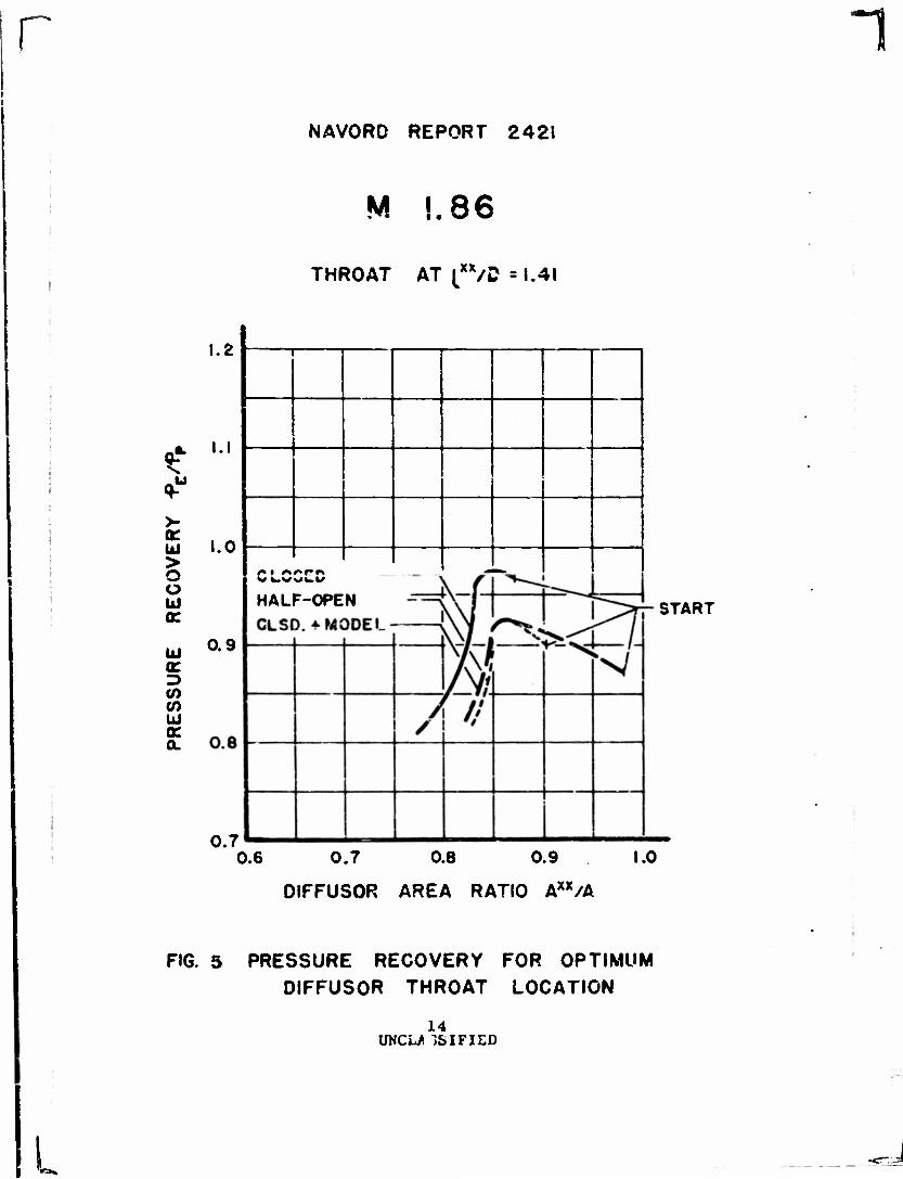
7. The pi tot recovery ig plotted versus the dlffuser area ratio in Figures 5 through 8 for the Mach numbers 1.86, 2.48, 2.83, and 4.32. Three curves are shown on each graph for the three duct configurations in- vestigated. The four graphs represent the relation of Pg/Pp vs. A**/A for the optimum diffuser geometry; i.e., for the location of the throat where the high- est recoveries were obtained. This optimum location is different for each Mach number and is noted on the graphs.
8. The break-off of the curves at the right e.nd denotes the minimum diffuser throat area required for starting the tunnel, while the left side break- off* marks the minimum area for running the tunnel.
9. It is seen that after supsraonie flow is established it can be maintained up to pressures which are larger than pitot pressure with the exception of the lowest Hach number. The gain in terms of pitot recovery be- comes more pronounced with increasing Mach number. A pressure ratio of s»F/Pp = 1.81 is reached at M = 4.92 with the present diffuser. The pressure recovery is adversely affected by a model in the test section or a half open test section. The added model gives the lowest recovery. The detrimental effect of the model is less pronounced at the higher Mach numbers where losses due to friction and wake are partly compensated by the oblique shock system added by the model. The effect of the model may be negligible at Mach numbers above? 6 as demonstrated in reference 10.
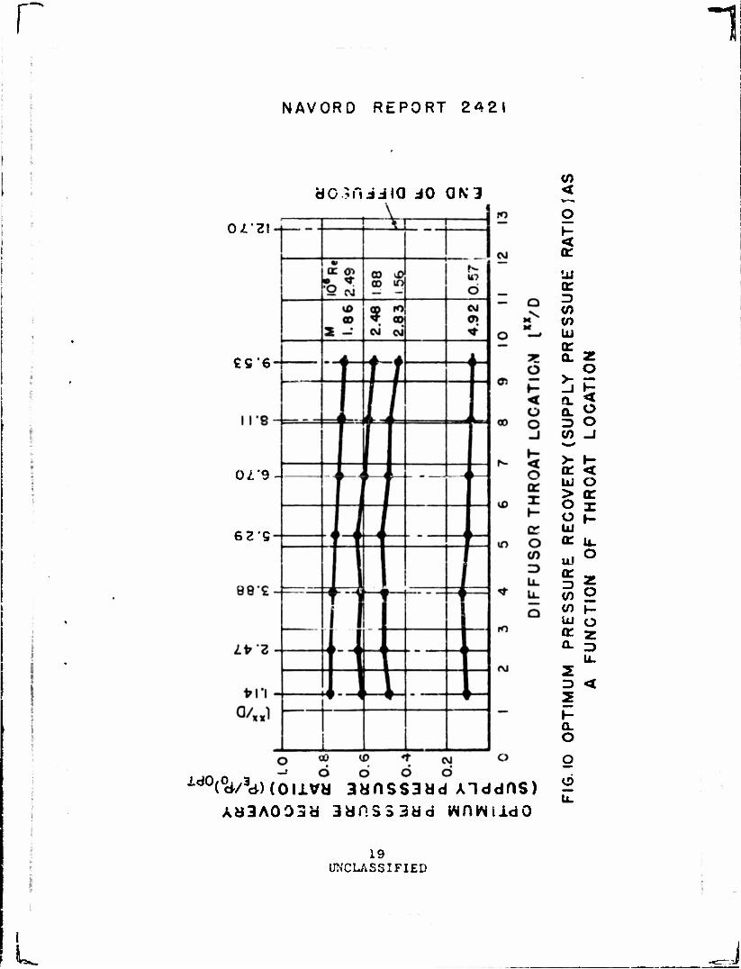
10. The influence of variations in throat location is shown in Figure 9 and Figure 10. Here, the high- est values of pressure recovery referred to pitot pressure and supply pressure obtained for the closed tunnel, (without * model), are plotted vs. throat location i**/D. I-c l«rmined b? the mechanical construction of the diffuser, the throat could not be shifted continuously but bad to be set at discrete points, the exact location of which is noted at the top of the figures However, there is good reason to assume that no extreme values were missed by the densely spaced settings. It must be realized that every vervical line in the graphs represents a diffuser
4 UNCLASSIFIED

i
L
1
UNCLASSIFIED w^VORD Report 2421
of different bs*ic aeometry and that the points snown indicate the optiaus. pressure recovery attainable.
11. It can be seen that in contrast to the pltot recovery the supply recovery decreases with Mach nuaber. This is to be expected from the fact that static pressure ratios drop strongly with increasing; Mach number. Furthermore the Reynolds numbers of the flow (noted next to X In Figures 9 and 10), decrease with increasing Xacb numbers, (constant supply pressure).
12. It is interesting to note the optiaus throat location in Figure 9. The optlaua of the recovery as a function of throct location is not pronounced up to M . 2.83. However, at M a 4.92 a definite optlaua is notsd st 4 D.
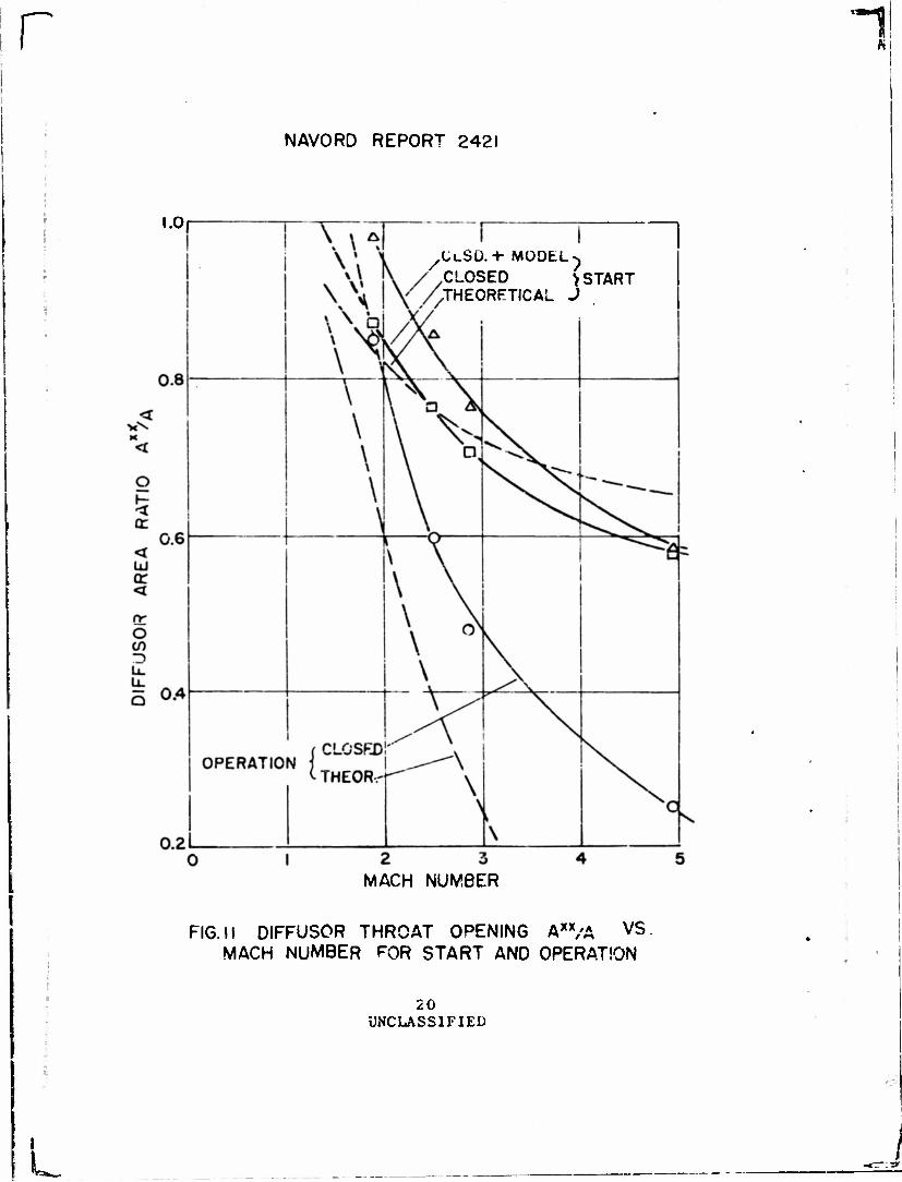
13. Figure 11 shows under the designation "operation, closed" a plot of the difivmmx area ratios that yield optlaua values of pressure recovery vs. Mach nuaber for the operating tunnel. Also given is the theoretical no«*le area ratio for potential flow. This curve represents an ldecl Halting case (reference 11) that can never be reached actually. The group of curves of the saae figure (Figure 11) shows the other diffuser area ratios required for starting the flow in the tunnel for the case of the closed tunnel and the closed tunnel with the model mounted in the air streaa. Additional area is required to start the tunnel with the aodel but this additional area becoaes saaller with increasing Mach nuaber and is insignificant at M - 4.92.
14. Another fact of practical laportance is borne out by ths experimental curves; i.e., that area ratios greater than 1 are required to start and operate the tunnel at a - 1.56.
15. The experimental values are compared with:
i** [A/A « £ *
the theoretical alnlaua opening (see e.g. referer.ee 11) required for "swallowing" the -^-ml shock. Here it is «een that the qualitative benavivi is well represented
5 UNCLASSIFIED

UNCLASSIFIED NAYORD Report 2421
by the theoretical curve ic & certain Hatch nuaber range ( 2<M<4 ) in which the deviation is approximately uOastAQt.
IS. The pressure ratio required for starting the flow in the tunnel is shown in Figure 12 as a function of the diffuser area ratio, TR© vertical tangents of the curves on their left indicate that closing the diffuser threat beyond a definite area ratio prevents the flow fros gsttlug established and that eves very high vacua are unable to overcome a ssall defect in throat area.
• 17. Although starting of th« tunnel in the fashion described in section III is not feasible at M r tVW'i it was possible ts establish and hold flow in the tunnel by first opening the blow-valve while having a plug is the nossle throat and then quickly removing this plug.
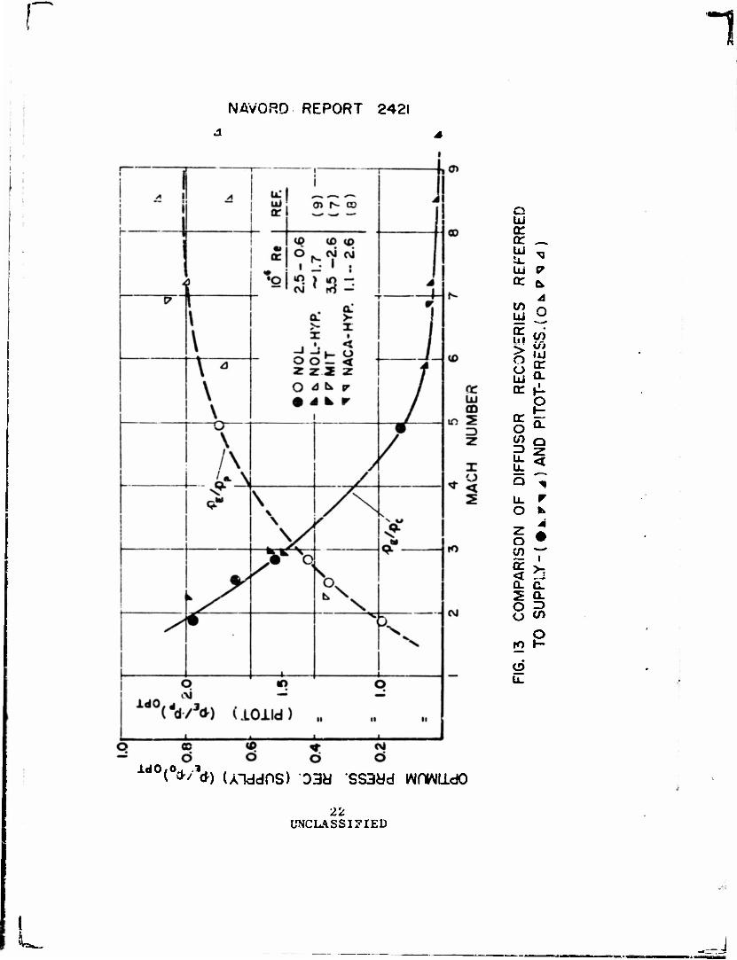
18. Figure 13 shows a cosparlsoa of the optisus pressure recoveries obtained at various facilities. The pressure data are compared with those seasured at »2T (reference 7) in the NACA Langley Hypersonic Tunnel (reference 8) and in the SOL 12 x 12 ca Hypersonic Tunnel Ho. 4 (reference 5), The solid line (p^/pn) represents the faired recoveries obtained in various tunnels. It is represented by
A a l.OSie -O.O&kfM*
in the range \.75<-t1* 6.5" <*>
All the tunnels are in the same range of Reynolds nuabers and have approximately stellar dlffusers.
19. The pitot recoveries are faired by the dashed Use end show scatter, that is not noticeable in the insensitive supply pressure recovery plot.
20. The optisua starting pressure, i.e., the highest pressures (referred to pitot pressure and static pressure) with which flow can be established are shown in Figure 14. THe results of the IfOL hypersonic diffuser investigation (reference 9) are also showa and again these data are on one curve with the data of the present investigation. The starting pressure referred to the pitot pressure shows the following deviation over the whole Mach nuafosr range:
3= 1 1 . U <~ It.5 V* so
/ (LB *M* 9.6) «) f.
ONCLaSSZFlaD
:
1
UNCLASSIFIED SAVCRD Report 2421
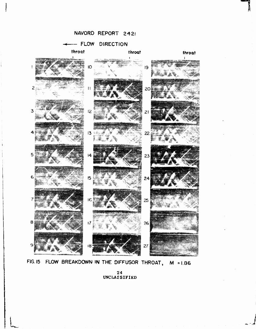
21. A series of schlieren picture frames of the flow in the diffuser throat selected from « «oving picture film is shown in Figure IS. The picture* w»re taken with rising pressure at the diffuser exit (left side) which produced finally the breakdown of super- sonic flow. The> were taken at a rate o£ 24 grasses per second and with a flow of H * 1-86 at the diffuser entrance. The 27 pictures selected are typical »si are presented in true sequence, however, they do not represent equal time inters!®. Th© shock system causing final transition to subsonic flow moves up- stream apprcechisg the throat, getting unstable,i.e., oscillating with increasing violence, until it finally passes the throat. Picture No. 12 is typical for the shock configuration with which the optimum recoveries are obtained and is similar to those obtained for tke other Mach numbers.
i
v, CONCLUSION
22. A two-dimensional. converging - diverging duct with plane walls is an efficient diffuser for a supersonic wind tunnel. In order to obtain optimum pressure rscorsriss store those of a pitot tube in the test section the throat opening of the diffuser pust be variable. Also the throat must be clots3 to a point where maxisroas pressure recovery is obtained after supersonic flow has bee;* established in the test section.
23. The distance of the throat from the diffuser entrance (or nozzle exit) that gives maximum pressure recovery varies slightly with Mach nunber and Reynolds number. However, it is possible to choose as a compromise for a practical design a fixed throat location such that the pressure recovery is reasonably constant over a wide range of Mach numbers.
ZA The pressure ratios needed to start the tunnel were found to be lower (closer to one) than those previously known.
7 UNCLASSIFIED

r 1
UNCLASSIFIED NAVORD Report 2421
VI. REFERENCES
1. See e.g Buseaann, A. flandbuch der Experlcantal- Physik IV, 1, 447, Leipzig 1931.
2. Oawatitsch, K.., "Pressure Recovery for Missiles with Reaction Propulsion at High Supersonic Speeds." NACA TM 1140, June 1947.
3. Kursweg, H. H., p. 1-2 of Zettler-Seidel, W., "Supersonic Diffusers", NOLM 8634, Naval Ordnance Laboratory, White Oak, Silver Spring, Md , 15 October 1946.
4. Henderson, Hayward W., "Naval Ordnance Laboratory 18 x 18 ca Supersonic Wind Tunnel-Design Criteria, Description of Tunnel, Operating Technique." NOLM 10379, Naval Ordnance Laboratory, White Oak, Silver Spring Md., 3 August 1949.
5. Kursweg, H. H. "A few aspects of future supor- souii: win* tunnel d««lga and test techniques." 0. S. Naval Ordnance Laboratory HOLE 1133, 29 June 1949.
6. Neuaann, E. P., Lustwerk, T. "Supersonic diffusers for wind tunnels." Journ. Applied Mech. 16, 2, 195, June 1949.
7. Neumann, E. P., Lustverk, F., "High Efficiency Supersonic Diffusers", Journal of the Aeronautical Sciences, p. 369-374, 18 June 1951.
8. Bertram, M. H., "Investigation of the Pressure- Ratio Requirements of the Langley 11-lnch Hyper- sonic Tunnel with a Variable Geoaetry Difxuser", NACA R M L 50 I 13, October 6, 1950, Declassified NACA change in classification Fora No. 750, 21 March 1952.
9. Wegener, P. P. and Lobb, R. K., "NOL Hypersonic Tunnel No. 4, Results II: Diffuser Investigation", NAVORD Report 2376, Naval Ordnance Laboratory, White Oak, Silver Spring, Md., 5 May 1952.
10. Lobb, R. K., "NOL Hypersonic Tunnel No. 4, Results III: jiffuser Investigation with Models and Supports", NAVORD Report 2435, 1 July 1952.
8 UNCLASSIFIED

1
11
UNCLASSIFIED NAVORD Report 2121
Ferri, A., "Eleaectd of Aerodynamics of Super- sonic Flows", p. 185, The SacMillan Company, Ms «»«•» V_ — t. 1 *J iS
12. Diggins. J. L., "Diffuser Investigations in a Supersonic Wind Tunnel", NAVORD Report 1570, Naval Ordnance Laboratory, White Oak, Silver spring, Md,, 3 January 1951. (Data of this reference are included in the present report
>_

NAVORD REPORT 2421
UJ z 2
»- o
(J) o co >
o UJ <
o CO
X CO
u.
10 UNCLASSIFIED

r 1 NAVORD REPORT 2421
.-
UJ e>
cr o •** t
ID li- nt. Q
CVJ
G:
ii UNCLASSIFIED
J
r 1 NAVORD REPORT 2421
</) Z O J- < o U. o o
o Q
O z <
o z <
Z Ul
(T O O
U. LL
o ro
o
12 UNCLASSIFIED
>>2»
r 1
NAVORD RPPORT 2 421
i i
<
UJ I o
o o I- o
O
13 UNCLASSIFIED
Sfes
L J
r n
L
NAVORO REPORT 2421
M |.86
XX.-| , THROAT AT fVD » 1.41
1.2
>- «r UJ >
o u
UJ tr (/>
UJ tr OL
I.I
/»• #s<*^r»
HALF-OPEN CLSO. 4 MODE!
0.9
0.7
START
0.6 0.7 0.8 0.9 1.0
DIFFUSOR AREA RATIO Axx/A
FIG. 5 PRESSURE RECOVERY FOR OPTIMUM DIFFUSOR THROAT LOCATION
14 UNCL/ 1SIFIED

r l NAVORD REPORT 2421
M 2.48
:XX, THROAT AT \,*7D =5.29
a.
>•
ill > O o Ui or
UJ or </>
Ui Q: CL
0.8
START
0.5 0.6 0.7 0.8 0.9
DIFFUSOR AREA RATIO AX5A
FIG. 6 PRESSURE RECOVERY FOR OPTIMUM DIFFUSOR THROAT LOCATION
15 UNCLASSIFIED
**_ J

r 1
NAVORD REPORT 242!
M 2.83
THROAT AT t*x/D « 5. 2.9
a. 0- s.
>
UJ > o o UJ or
UJ or </> </> UJ or. A
START
FIG. 7
0.4 0.5 0.6 0.7 0.8
DIFFUSOR AREA RATIO Ax*/A
PRESSURE RECOVERY FOR OPTIMUM DIFFUSOR THROAT LOCATION
1C UNCLASSIFIED
L

1
NAVORD REPORT 242!
M 4.92
THROAT AT [•/0 s3.88
UJ > o o UJ cr
UJ
« CO UJ a: Q.
START
xx DIFFUSOR AREA RATIO A /A
FIG. 8 PRESSURE RECOVERY FOR OPTIMUM DIFFUSOR THROAT LOCATION
17
UNCLASSIFIED
W

NAVORD REPORT 2421
1
*3dlQ dO QN3 OJ"?.! 2
£5*6
!l'8
01 9
62 S
88£
Zfr"3
I*! 4X14-4-4
C\J
en
oo
10
m
<
CO* UJ
Q (T
M
o
S 5 <
—' u > o o uJ d
x
to
CM
or o a) 3 U. U. o
UJ or ID cn CO UJ a: Q.
2 3
= CO H- < CL O
2 O
h- < o o _l
h- < o <r x r-
U. o
o 3
CO «D V CM d C9
(ouva 3cjnss3yd xoiid) ld0(dd/36) AH3A003H 3dnSS3dd WDWIldO
18 UNCLASSIFIED
r NAVORO REPORT 2421
ac.;niiia do ON J
OL'Z\
£S*6
0Z*9-
629
ld0(V3d)(oiiVd 3«nss3dd Aiddns) A«3A003d 3dHSS3dd wr.WiidO
<
< a:
cr Z3 CO if) \ii a: a. z
o
3 O V) -I
< o tr x
u. o
a: UL) > o o UJ or ul
3 i CO h- UJ o * z
z 3 <
h- a. o g
u.
19 UNCLASSIFIED
U
r -T
NAVORD REPORT 2421
1.0
CLOSED >START .THEORETICAL
MACH NUMBER
FIG. 11 DIFFUSOR THROAT OPENING Axx/A VS. MACH NUMBER FOR START AND OPERATION
20 UNCLASSIFIED
L_

r 1 NAVORD REPORT 2421
in
O
o
L?_GO O)
V o
1
1 1 1
i 3 1 rJ op s o
1 GO <\1
N
1 1
o
f
cn <£> o
—
<0 o
< or y
X <
g < cr
< UJ or <
or o en ZD U. U. O
00 6 v* d d
cv; d
o CO 3 U.
<
UJ or z> </> (/> Id a: a.
z. I- <
co
CJ
u.
O
< o or X
cr o CO
U.
a. o or o
< or <
tr <
onvd 3dnss3ad ONiiavis
21 UNCLASSIFIED
I i
NAVORD REPORT 2421
c LkJ
tr UI
Ui Q:
</> UJ cr > o o cr
cr o o
o
Q.
Q 2 <
u_ r O *
IS 2 £: O ^ O CO
e
IdO/O (°*'V) (XlddPS) 03d SS3Ud wnwiido
22 UNCLASSIFIED
L

r n
L
NAVORD REPORT 2421
4 6 MACh NUMBER
FIG. 14 COMP. OF STARTING PRESSURES REF TO STATIC- (OM AND PiTOl" PRESS. (•*>)
23 UNCLASSIFIED
NAVORD REPORT 2421
FLOW DIRECTION throat throat throat
*7m*jS* " 26
FIG. 15 FLOW BREAKDOWN IN THE DIFFUSOR THROAT, M =1.36
24 UNCLASSIFIED
1
L
Aeroballistic Research Department External Distribution List for Development (X2)
Copies Chief, Bureau of Ordnance Department of the Navy Washington 25, D. C.
1 Atth: Rea ~ 1 Attn: Rexe 1 Attn: Be3d 3 Attn: Re.9a
1 z
Chief, Bureau of Aeronautics Department of the Navy Washington 25, D. C
. Attn; AER-TD-414 . Attn: RS-7-
Gommander - U.S. Naval Ordnance Test Station Invoke r« P.O. China Lake, California
Attn: Technical Library
Commander U.S. Naval Air Missile Test Center Point Mugu, California
Attn: Technical Library
Superintendent, U.S. Naval Postgrad a-te Sehool Monterey. California
Attn: Librarian
Commanding Officer.and Director David Taylor Model Basin Washington 7, D. C*
Attn: Hydrodynamics Laboratory
Chief of Naval Research' " Navy Research Section L/arary of Congress Washington 25, D. C.
Chief, Naval Operations Department of the Navy Washington 25, D. C.
Attn: Op-51
Office of Naval Research Department of the Navy Washington 25, D. C.
Attn: Code 463
Director Naval Research Laboratory Washington 25, D. C.
Attn: Code 2021 Code 3800
Off i c e r -in -Cha r ge Naval Aircraft Torpedo Unit U.S. Naval Air Station Quonset Point, Rhode Island
Office, Chief of Ordnance Washington 25, D. C.
Attn: ORDTU
No. of '... _.. Copies
Research aiidBeveiopmeht Board Library Branch Pentagon 3D 1041
2 Washington 25, D.C. . ?
CUief, AFSWP P.O. Box 2610 Washington. D. C.
1 Attn: Technical Library
Chief, Physical Vulnerability Branch Air Targets .Division .-. : ••—..__'..;-;_../ Directorate of Intelligence- ;- > - r
Headquarters, USAF ..".'• XI-IT?'^ 1 Washington 25, D. C.
Xhc r*x tillcry7:School. • ,.:
Antiaircraft and Guided Mi5.siles Br. Fort Bliss, Texas;;
2 Attn: Research and Analysis Sec.
Commanding General Wright Air Development Center Wright-Patterson Air Force Base Dayton, Ohio
8 Attn: WCAPD Z- Attn: WCRR _ ... . _
'.. 1 . •:• - Attn; WCSD - 5_.; _ Aitn:_WCSO .. , -
Director Air University Library .'-_
\ Maxwell Air Fares Base, Alabama
Commacding Gen^.z^X-i^—:—- '-•— - '.-,.. Aberdeen Proving Ground
Aberdeen, Maryland 1 Attn: C.L. Poor
National Bureau of Standards Washington 25. D. C.
1 Attn: Librarian (Ord. Dev. Div.l 1 Attn: W. Ramberg
National Bureau of Standards Corona Laboratories (Ord.Dev.Div.) Corona, California
- 1 Attn: Dr. H. Thomas
National Bureau of Standards Building 3U, UCLA Campus 405 Hilgard Avenue Los Angeles 24, California
1 Attn: Librarian
University of California BerkeJey 4, California
1 Attn: Mr. G- J. Maslach 1 Attn: Dr. S. A. Schapf
California Inst. of Technology Pasadena 4, California
2 Attn: Librarian(Guggenheim/.-ro. Lab. VIA: BuAero

No. of Copies
No. of Copies
University of Michigan tin II r-» r»_ -t .-. tf xxi.ow mill l\c atafvii O Ypsilanti, Michigan
Attn: L.R. Biaseil VIA: InsMat
University of Minnesota Rosemount, Minnesota
Attn: J. Leonard Frame VIA: Ass't InsMat
General Electric Company Buiiding § 1, Campbell Avenue Plant Schenectady, New York
Attn: J.C. Hoffman VIA: InsMachinery
The Rand Corporation 1500 Fourth Street Santa Monica, California
Attn: The Librarian VIA: InsMat
The Ohio State University Columbus, Ohio
1 Attn: G.L. VonEsctten VIAr Ass i InsMat
Polytechnic Institute ttf Brooklyn 99 Livingston Street Brooklyn 2, New York
1 Attn: Dr. Antonio Ferri VIA: ONR. Branch Office
Princeton University Forrestal Research Center Library Project Squid
V- Princeton, New Jersey
Massachusetts Inst. of Technology Project Meteor Cambridge 39, Massachusetts
7 A * *„ . /"•..; J — -3 »'I '-^ I . H r'l r vr u A^iii. •-• I *-T .." * - tVii-=.=:r*u "- L..rary
Applied Physics Laboratory The Johns Hopkins University 8621 Georgia Avenue Silver Spring, Maryland
1, Attnr Arthur G, Norris Technical Reports Office
VIA: NIO
Armour Research Foundation 35 West 33rd Street Chicago lb, Illinois
1 Attn: Engr. Mechanics Division VIA: ONR Branch Office
Defense Research Laboratory University of Texas Box 1, University Station
1 Austin, Texas VIA: InsMat
Eastman Kodak Company Navy Ordnance Division 50 West Mair. Street P.ochester 4, New York
2 Attn: Dr. Herbert Trotter, Jr. VIA: NIO
Consolidated Vultee Corporation Daingerfield, Texas
1 Attn: J.E. Arnold, Manager VIA: Dev. Contract Office
Douglas Aircraft Company, Inc. 3000 Ocean Park Boulevard Santa Monica, California
1 Attn: Mr. E.F. Burton VIA: BuAero Resident Rep.
North American Aviation, Inc. 12214 Lakewood Boulevard Downey. California
2 Attn: Aerophysics Laboratory VIA: BuAero Rep.
National Advisory Committee for Aero. 1724 F Street Northwest Washington 25, D. C.
5 Attn: Mr. E. B. Jackson
Ames Aeronautical Laboratory Moffett Field, California
i Attn: H. Julian Allen -2 Attn: A.C. Charters
Theoretical Aerodynamics Division Langley Aeronautical Laboratory Langley T'ield, Virginia
1 Attn: Theoretical Aerodynamics Div. 1 Attn: Dr. A. Busemann 2 Attn: J. Steele
NACA Lewis Flight Propulsion Lab. Cleveland Hopkins Airport Cleveland, Ohio
1 Attn: Dr. John C. Evvard
Hughes Aircraft Company Culver City, California
1 Attn: Dr. Allen E. Puckett
Institute of Aerophysics University of Toronto Toronto 5, Ontario
1 Attn: Dr. Gordon N. Patterson, Dir. VIA: BuOid (Ad8)

1
Aerobalhstu- Research Department External Distribution LI at for Development (X2a)
No of Copiea
Nation*! Bureau of Standards Washington 25, D. C.
1 Attn: C. B Schubautr
Graduate School of Aero L'ngr. Cornell University Ithaca, New York
1 Attn: W R. Seara VIA: ONR Branch Office
Applied Math, ana ,St«>.*iics t^ao. Stanford University Stanford, California
1 Attn: Mr. R. J. Lar.gle VIA: Asa't InsMat
Harvard University 109 Pierce KaU Cambridge 38, Massachusetts
1 Attn: Prof. R. von Mises
'
H