Embed Size (px)
Citation preview
UNCLASSIFIED
AD NUMBER
LIMITATION CHANGESTO:
FROM:
AUTHORITY
THIS PAGE IS UNCLASSIFIED
AD480031
Approved for public release; distribution isunlimited.
Distribution authorized to U.S. Gov't. agenciesand their contractors; Critical Technology; JAN1966. Other requests shall be referred to AirForce Flight Dynamic Laboratory, Attn: FDTR,Wright-Patterson AFB, OH 45433. This documentcontains export-controlled technical data.
AFFDL ltr, 15 Feb 1973
AFFDL-TR-65-213, PART I
CO
O STATICS AND STABILITY OF THIN-WALLED ELASTIC BEAMS
CD PAR? I FORMUUTION OF FUNDAMENTAL EQUATIONS
PROF. E. GIANGRECO JNG. M. CAPURSO
ING. M. COMO
INSTITUTE OF STRUCTURAL ENGINEERING UNIVERSITY OF NAPLES
NAPLES, ITALY
TECHNICAL REPORT AFFDL-TR-e5-213, PART I
JANUARY 1966
AIR FORCE FLIGHT DYNAMICS LARORATORY RESEARCH AND TECHNOLOGY DIVISION
AIR FORCE SYSTEMS COMMAND WRIGHT-«ATTERSON AIR FORCE RASE, OHIO
Distribution of This Document Is Unlimited
-
...
THIS DOCUMENT IS BEST QUALITY AVAILABLE. THE COPY
FURNISHED TO DTIC CONTAINED
A SIGNIFICANT NUMBER OF PAGES WHICH . DO NOT
REPRODUCE LEGIBLY.
NOTICES
When Government drawings, specifications, or other data are used for any purpose other than in connection with a definitely relateu Government procure- ment operation, the united States Government thereby incurs no responsibility nor any obligation whatsoever; and the fact that the Government may have formulated, furnished, or in any way supplied the said drawings, specifications, or other data, is not to be regarded by implication or otherwise as in any manner licensing the holder or any other person or corporation, or conveying any rights or permission to manufacture, use, or sell any patented invention that may in any way be related thereto.
Copies of this report should not be returned to the Research and Tech- nology Division unless return is required by security considerations, contractual obligations, or notice on a specific document.
300 - Maxch 1966 - 773-34-730
STATICS AND STABILITY OF THIN-WALLED ELASTIC BEAMS
PAim FORMULATION OF FUNDAMENTAL EQUATIONS
PROF. £. GIANGRECO INC. M. CAPURSO
1NG. M COMO
INSTITUTE OF STRUCTURAL ENGINEERING UNIVERSITY OF NAPLES
NAPLES, ITALY
Distribution of This Document Is Unlimited *
4
FOREVJOI-.L
This report was prepared by the University of Kapies, under USAF Contr-ctKo. AT 6l(05?)-6l3. The contract was initiated under Project Ko. li,67. Task ^. 1^6703; BFSK 4(6899-6l43OOlij-O000-6OO-FD). The work was adtainistered under the direction of the Air Force Flight Dynamics Laboratory, liesearch and Technology Division, Mr. Adel Abdessalara and later iir. Royce G. Forcaan acting as project engineers.
This report covers work conducted from February I965 to June 19^5.
The work was performsd by the Institute of Structural Engirieering, University of Naples, Kaples, Italy.
This technical report has been reviewed and is approved.
11
STATICS AM) STABILITY W THIN WALLED ELASTIC BEAMS
ABSTRACT
Formulation of fuadiaental equation« of elastic equilibrium of thin
walled beans subject to general loads and dislocations starting only
fro» the hypothesis of non deforaed transverse cross sections.
Fomulation of the fundanental equations of dynaaic stability of thin
walled beaaa subject to general conservative loads and dislocations
by use of a systematic geoaetrical approach.
TABLS OF COWTKNTS
1) STATICS
1.1) Introduction
1,2} The basic hypothesis
1.3) Kineutic relations
1.4) Elasticity relations
1.5) Equilibriua equations
1.6) Basic equations of elastic equillbriuB of thin walled beaa having continuous directrix end constant thickness
1.7) Bouadary conditions connected with baste equation
1,6) Basic equ;clon extended to thin «rdllsd b@&»s having discoutisuous directrix and discostim^ous constant thiefesess
ltg) Conclusions
2) mmthiTi
2 JLJ Ietro4uc t ion
2.2) General rsaarks on spprosch asthod
2.3) Effects due to flesural aotlon
2.4) Effects due to torslonal vscillatlon
2.5) Effects due to eztenelonal cscillation
2.6) General equations of dynamics of thin walled beams
References
Page 1
3
3
7
S
15
IS
22
26
31
40
48
50
52
ill
i) srarics
1,1) Introduction
Tb« theory of «lastic equDlbrlua of a cyllndar subj«ct to
loads applied at the bases and represented by ■ general systea of
balanced forces, ha« been accurately and completely developed by St.
Venant (l] [sQ «1th the traditional hypotheses of OM^aneity, isotropy
and linear elasticity.
This study represents the background of the so called "technical
theory of the beaas" which applies with approziaation the results obtained
by St. Venant to all the real case« concerning the elastic equllibriua
of cylinders subject to any type of loads und constraints.
Such application is founded in a classic postulate carryini,
St. Veuant's -aaas and is synthetically expressed by the following
principle: "if a systea of balanced forces acts on a Halted area S'
of the surface S of a body, its effects daap out as they leave S' and
actually Gisappear at distance O depending upon the shape and th« 5i$e
of s";
Such postulate peraits to deteraine stresses and dlsplaceaosts
Having knowledge only of six clasuic stress characteristics coänected
with the constraints and Hada applied to the body, the areas close to
constraints »r concentrated loa^s excluded.
However, soae conditions are indispensable; of which the moat
iaportant are:
1) the cross section diaensions aust be coaparcble;
2) the body's length aust be auch greater than the above mentioned
cross diaensions.
It is the classic case of solid section beams for which the
technical theory has a good correspondence with reality.
The saas thing does not apply to thin walled beams. In fact,
auch structures are characterized by three diaensions, anyone of which
is negligible if coapared to the next one:
a) thickness of the wall
b) average dimension of the cross section
c) length
For this type of structures, which are always more widely used
by technical practice, it has been necessary to generalize the results
obtslced by St. Venant, specifically ss i«r as toraioaal stresses are
concerned; a new theory has been ezpxesscd Justifying, with s*>prozl~
■atlon, the dlscrepanciea b«t«een technical theory and teat controls.
This new theory known as "the theory of sectorlsi n~z*s",
developed by VlaaovQiQfO *nd Tlaoühenso föj [öj for bssss of open
cross section, has been la\er jenorslijsd by EarBan-Chrlstensea i?J
for teaKS of general zross '»sctioc.
Vlasov EykJ, Ws^ier [sj, Kappus [s], Goodier [lo] . etc.
applied this theory to the problea of elastic equtlibrlua gt»i.iiity
and thetr r»3ults have been confirmed by t*!3t controls.
Nevertheless, as It has been noticed by Karasn-Vgi^Zang-
ChisD liij , vhe sectorial area theory is only the fir.it tera of a
repetition procedure the validity of which Is in certstn case« doubtJf ul.
auch theoryj 1;. fact, basically consists is dividing th?
ebesr flow produced by tha twisting soss&nt into tso p*ris: the prissry
Siiear fio« typlcsJ. e* 3t. Venaat'a theory, sod the secosdary shear
flo» säso^ist^d with the asfsa) ctresss* csassd by the ■scn-unifGrs
särplag of e?«>»s ßäctioas dus to the jprisasry fio*.
Iss faet, th* sect'n-lsl areas theory r^iijisis into ths cls^äis
salutioa of St» Vsasnt *h«n fi^isiDg is ccaätsst is the length of ths
lass. Hcweves-, this theory aegiect* the T?arpiss caaged &y tne ssecoadar^
gheer fioe whi2h sossstt^s saa be ssr« tonspieusus tLi»n the prlaary one,
sad; coE«equsBtlyf faaoaissEtally chsnges the static condition; further-
sores said tfesery, -ives isproving eoßaidsrably the correctness of cal-
culation of stresses aad deformations inside the body, cannot be applied
in the areas ^nich sr$ olo««» to conncrminte or concentrated loads.
As £ cooclusion, ss can say that the "sectorial areas theory"
ig for the thin wslled beaas ehat the "technical theory" is for the
solid section beau; in other words, the liaitations of both en be
coneidercd identical.
Therefore, in this Note we want to re-examine froa the origin
the problefih-of-slaetle-equilibriuB of thin welldMaewwsabject to very
general loads and t*1»locations, making use of a very general nethod.
In fact, the correct solution of the probleas pemtts to
eliminate the liaitations related to St. Venant*s postulate and to
determine exactly soae problems of considerable interest for the theory
as vail a.i for the practice, as:
1) the calculation of stresses in the areaa close to concentrated
loads snd external constraints;
2) the calculation of stresses associated w;lth general loads acting
on the surface of the beam;
•) >.ne calculation of stresses associated it'a general dislocation,
of general Interest for the study of therslc or plastic actions.
In the first part of this study the prob.'.ea of elastic equi-
librium of thin walled beams will be considered fro.i a general viewpoint
sad basic equations and boundary conditions will be furnishedi then,
above »ntloned problems will be studied and solved.
1,2) Tbs sssic hypothesis
The basic hypothesis on which we found our study is the
hypothesis of a transversaQf indefontable cross section. Such hypo-
thesis vhich appears also in the theory of sectorlal areas and in
Sarssn's study, is generally acceptable for the thin walled beams
because of shear dlaphrams used for structures of this type with
the purpose of avoiding the buckling of the wall.
Such dlaphrams are usually realised by msans of thin plates
welded to the wall, in order to avoid defoittaticcs of tha cross section.
Nevertheless, being such plates very thin, we can imagine
them having no resistance to warping outside their plane, and, conse-
quently, leaving the beam cross section free to warp.
Therefore, in this study we will consider the profile as
uniformly stiffened along its whole length, that is, we will consider
every section as keeping unchanged its shape during the displacement
associated with general loads conditions.
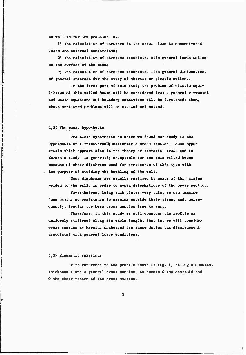
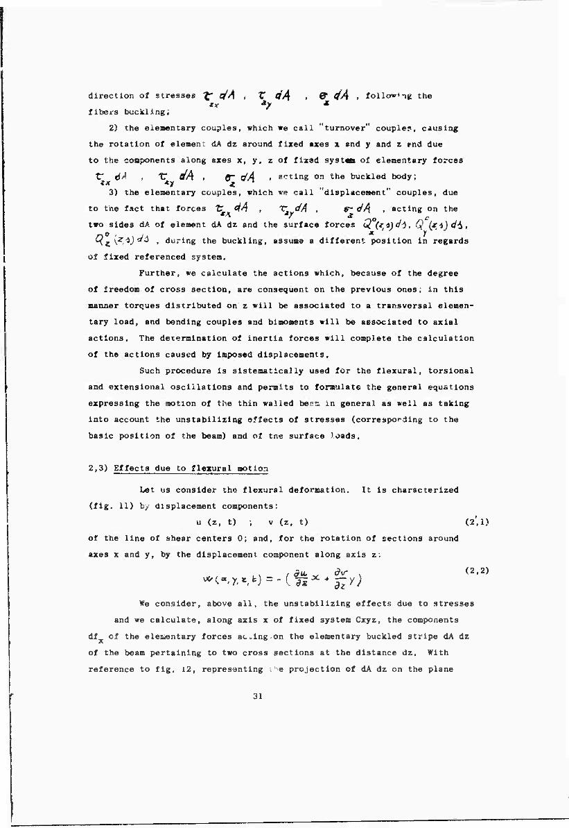
1,3) Kinematic relations
With reference to the profile shown in fig. 1, having a constant
thickness t and a general cross section, we denote G the centrold and
0 the shear center of the cross section.
•■»■
Pig. 1
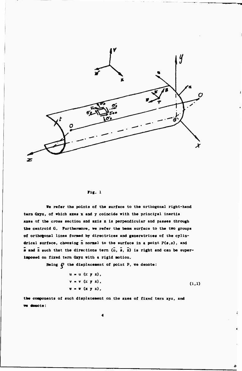
We refer the points of the surface to the orthogonal right-hand
tern Qsjz, of which axes % and y coincide with the principal Inertia
Utes of the cross section and axis z Is perpendicular and passes through
the centrold G. Turtheraore, we refer the bean surface to the two groups
of ortbo|^mal lines foraed by directrices and generatrices of the cylin-
drical surface, choosing n normal to the surface in a point Pirn,*.), and
• and z such that the directions tern (n, a, z) is right and can be super
iaposed on fixed tern Qxyz with a rigid action.
Being P the displaceaent of point P, we denote:
u » u (J: y z),
v m v (i: y z) ,
w « w (x y z), (1,1)
the coaponents of such displacenent on the axes of fixed tern xyz, end
we denote:
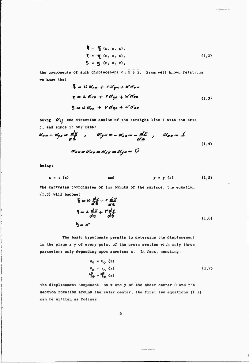
I = \ {.a, a, z) ,
f ■ H, (n, », E> , (1,2)
^ K ^ (n, s, z),
the components of such displacement OR a s z. Fron well known relat... s
we know that:
v • u. «0« + Y9(%* 4- iS**» (lf3)
being t/ij the direction cosine of the straight line 1 with the axis
j, and since in our case:
OCmt *r Cfmm » Gf/tm » &** — *^
(1,4^
being:
x = Jt <s) and y = y (s) (1,5)
the cartesian coordinates of tiug points of the surface, the equation
(1.3) will becoae:
dfs aft (1.6)
The basic hypothesis permits to deternine the displacement
in the plane z y of every point of the cross section with only three
parameters only depending upon abscissa z. In fact, denoting:
Uo = "o W
Vo * v0 (z) (1,7)
% - f. U) the displacement component on x and y of the shear center 0 and the
8«ction rotation around the s<uar center, the first two equations (1,1)
can be written as follows:
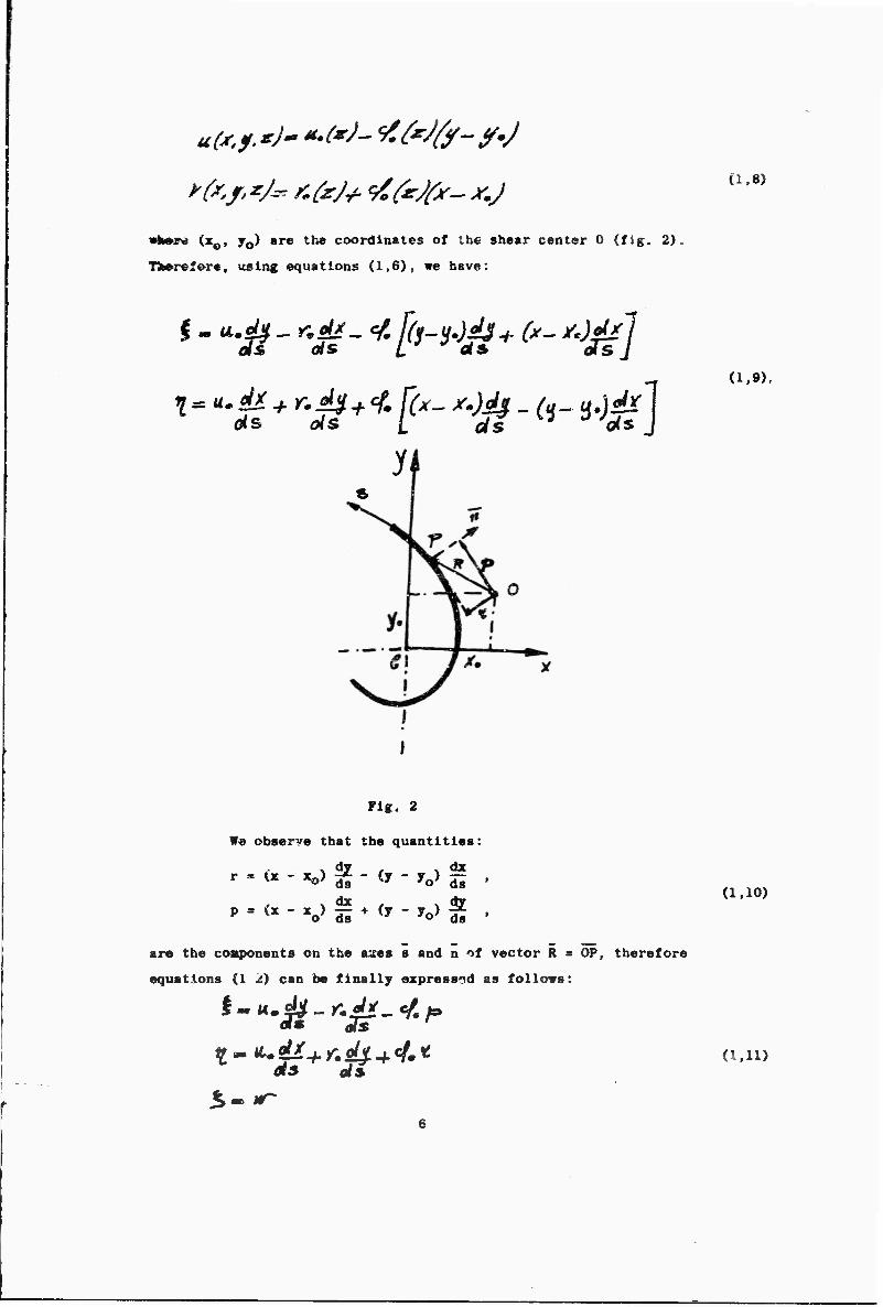
■rt»re (x0, y0) «re the coordinates of the shear center 0 (fig. 2),
Tierefore, using equations (1,6), we have:
Cl,8)
(1.9).
Fig. 2
We observe that the quantities:
»•»<«- «o> S ' «y - yo> fs
<x . dx , . dy
xo) d^ + <y " yo) S
(1,10)
er« the coaponents on the aues s and n of vector R s OP, therefore
equations (1 2) can be finally expressed as follows:
ms ols (i,ii)
Consequently; the aotion of every point of the bean is expressed
by the following four functions:
Uo * u0 U) ,
vo " vo <s) •
• a • (n,s,z) ,
and the latter can be considered, with a good approziution, independent
of n, in consideration of the ssallness of thickness t, and can be
written:
w . w (s.z) . (1,13)
1,4) glasticity relations
If we neglect the normal stress STJt , we can espre^s as follows
the relations between the stresses components and the unit strains in
the thin wall surface:
In a eore general case the strain components will be expressed
by the following relations:
(1,15)
where * is the elastic strain and S the strain due to a general
dislocatioi. systea, ad a thermic, plastic system etc.
So equations (1,14) can be written:
(1.16)
Furtbernore, the basic bypothasls pcralts to reduce the
uzümovns; in fact, since «e must have:
•s= 0 (1.17)
for the cross iodeformability of the section, the norul stress G» can
be expressed:
6;-yöV- fm? (i,i8)
while the shearing strain JTrnm can ^ expressed as follows:
«here 2% , ify , and /^ are general functions of x.
The basic unknowns, expressed as special stress coaponents,
can be reduced to the following two functions:
where; *—&?&• - ^ *#~ * *J
(1,20)
«■«-«*/-• "fiS* ci .21)
Taking into account the classic relations:
equations (1,20) CLU be written as follows for (1,6):
(1.22)
1,23)
and they express the general elasticity relations of thin walled beans.
£4uations (1,23) represent the valuers of normal stresses «5^
and shear stresses ü'n9 corresponding to the aiddle fiber of the wall
foraiug the profile.
In reality such stresses vary along thickness t of tho wall,
but actually they can be considered constant because of the thickness
saallness. However, if the profile has open cross section, it is neces-
sary to consider, together with the stresses (1,23), the shearing stres-
ses linearly variable along the thickness and vanishing in correspondence
with tho middle fiber associated with the twist of the wall caused by
external torque.
3uch stresses, classic of St. Vcnant's study, can be expressed,
with good approxiaatlrn, «a follows:
being n inS dlstanje becween the fiber aad the ciddls surface; in fact,
said stresses ar^ the only ones which develop for a constant twist of
the bean and, consequently, allow the bean to balance the external
torque.
In fact, as a result of (1,24) we obtain a twisting nosent
H , having the well known expression:
being J the torsional rigidity which, in case of open sections of
constant thickness t , is written:
3 where m is the length of the middle line, and in the case of cross section
consisting of several portions of different thickness t^, is:
* 3
If the profile has a close section (box or milticell beam),
stresses (1,24) are no more necessary to give torsional rigidity to the
beam. In fact, also in case of constant twist, the external moment is
almost completely absorbed by a flow of shear stresses constant along
the thickness; and, compared with such stresses, the contribution given
by equations (1,24) is quite unimportant.
Therefore, in these cases, stresses (1,23) are sufficient to
balance any external action and, consequently, are the only stresses
which are considered acting on the wall.
1,5) Kquilibrium equations
With reference to the wall element ds dz inside point P(s,z)
of the middle surface, the equilibrium equations to be imposed coincide
with the three equilibrium conditions relative to the displacement along
axes n, s, z. The first two, concerning the equilibrium along normal n
and tangent s, become unessential because of the hypothesis on the inde-
9
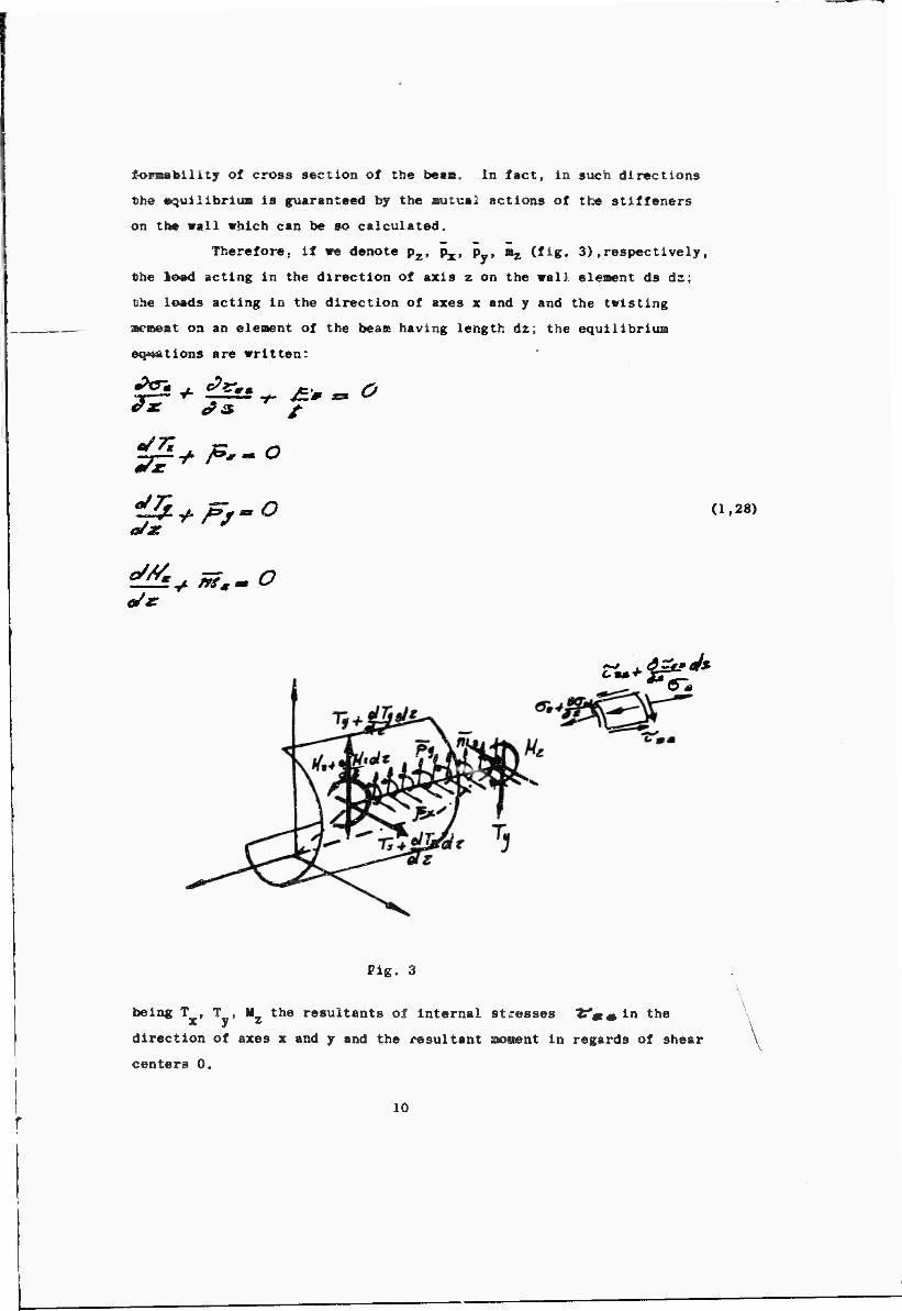
foraability of cross section of the besa. In fact, in such directions
the »quilibriua is guaranteed by the sutual actions of the stiffeners
on the wall which can be so calculated.
Therefore; if we denote p2, px, p , ^ (fig, 3).respectively,
the loed acting in the direction of axis z on the wal] eleaent ds dz;
Che loads acting in the direction of axes x and y and the twisting
scment on an eleaent of the beaae having length dz; the equilibrium
equations are written:
£.'* S
(1,28)
Oil
Fig. 3
being T . T , M, the resultants of internal stresses VÄÄin the x y i direction of axes x and y and the resultant saonent in regards of shear
centers 0.
\
10
These latters can, therefor«, be expressed as follow«:
7Z~ fzrmmsU9lÄ a/*
(1.29)
A
being M the Internal moment expressed by equation (1,25) and associated 2*
to stresses 2«« which «111 be taken into account only in the case of
open sections.
The last equation (1,29) can have the same for« for open
sections as well as for box or «ulticell sections, by introducing a
warping function associated with constant twist.
Such function, which we denote COm , represents the axial
«arplog function w(s) of th« points of th« «all alddle line «hen subject
to a constant torque having unitary negative gradient "yr*
In the case of open section beaas, such function is obtained
by observing that, since, in accordance «ith St. Venant's solution,
&M0 equals 0 in correspondence «ith the middle line, the second
equation (1,23), having:
(1,30)
gives:
a/& (i.3i)
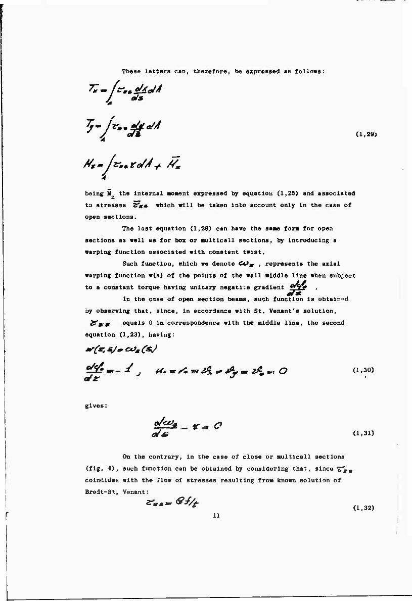
On the contrary, in the case of close or aulticell sections
(fig. 4), such function can be obtained by considering that, since ff9
coincides «ith the flow of stresses resulting fro« known solution of
Bredt-St, Venant:
* (1,32) 11
t»elng f the flow constant (♦), the second equation (1,23), in conside-
ration of (1,30) and (1,32), gives:
tt/oej. (1,33)
Fig. 4
(*) We sust reaeKber that flow constants f, for every element of aulticell
section, can be obtained with the partial flow f1 and f^ relative to
■eshes i and k having such eleaents in comon. The partial flow constants
f^ can finally be obtained from aonodroslc condition of */" and, con-
sequently, of ctf* which Imposes for every circuit the following relation:
ftSs-fe ±t/s~ O (1,33)'
fro« which, denoting .&/the area enclosed by circuit i, we obtain:
SS2;-. /t^ y. JE:/,*^ ^ O (i,34)
where Of; represents the geometric clrcuitation:
relative to the whole circuit 1 and &/# represents the partial geome-
trical clrcuitation of the element in common to meshes 1 and k. Eqs. (1,34)
represent a system which is linear for unknowns f. and of simple solu-
tion. In view of the above it is easy to obtain constants f.
12
Therefore, from equations (1,31) and (1,33), with a sitrr.le
quadrature procedure, ve can obtain, neglecting an arbitrary constant,
the expression of function C*JK . In general the constant Is elimi-
nated with the auxiliary condition:
/«/„ «^/-r O (1,35)
Thus, equations (1,29) can be written as follows:
/ o/s la/* for open sections, and:
for close or BUlticell sections.
Denoting ttc the nuaber of close aeshes of cross section, fro»
•quatlona fl.23) wa have: —— .
(1.37)
taking into account the relations:
equation (1,38) gives:
(1,39)
(1.40)
13
and, iatroduclng th« Dotation:
itio« (1,37) can be vrltt*n as follows:
(1,41)
and It appears identical to the equation already obtained for open
•ectiooe and expressed by (1,33),
Therefore, without considering the type of beaa cross section,
equations (1,29) can be written as follows:
0/s.
t'/r-'g" (1,42)
reisulting connected to the cross section geoiietry b> the three basic
functions:
x ■ x (s) y » y (■) CJL>g * CtV»)
For these functions, ve mist rekeaber that, since we chose
axes x and y as aain Inertia axes and the center or rotction 0 as shear
center of the section, we will always have the basic relations:
In fact, we can ootaia the coordinates x and y of com n "t
rotation 0 by iaposlng the last two equations (1,43), or by using
Jouravsky's procedure for close or cellular sections [,12j ,
(1,43)
14
1,6) Basic equations of el«»ttc equilibrium of thin wall»d be»« having
continuous directrix and coactant thlcknes«
We can now obtain the basic equations of elastic equillbrlua of
thin vailed beams, by changing the Indefinite equilibrium equations (1,28)
into terms of displacement. For the moment, since *« consider the body
free in the space and subject to a system of balanced forces, we know
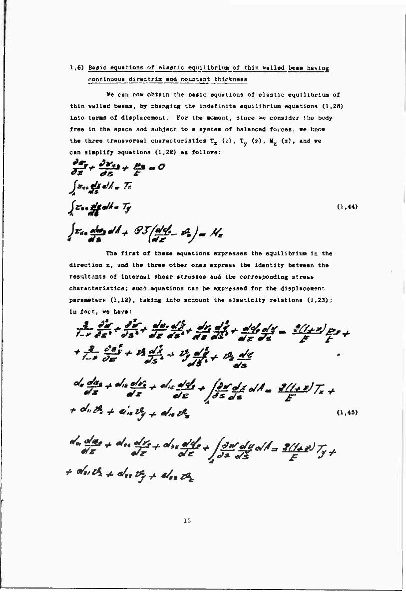
the three transversal characteristics T_ (z), !„ (z), M, (z>, and we * y z can simplify equations (1,28) as follows:
3*^ 48. ^ t
The first of these equations expresses the equillbrlua in the
direction z, and the three other ones express the Identity between the
resultants of Internal shear stresses and the corresponding stress
characteristics; suc^i equations can be expressed for the displacement
parameters (1,12), taking into account the elasticity relations (1,23);
In fact, we have:
(1,44)
** ** */s J<ßs e/* f
i:
after introducing the notations:
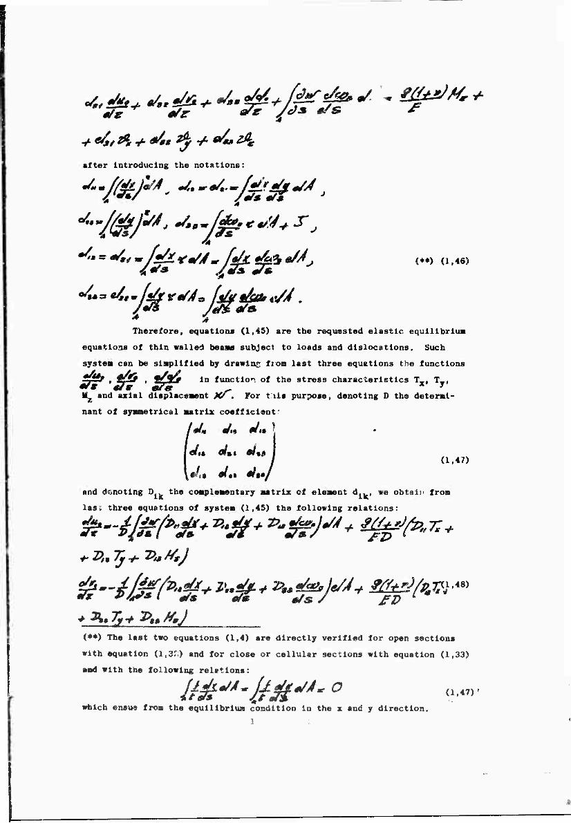
f ^"*^*~/&*m/J*/dce&&*/J* c*) (1,46)
Therefore, equations (1,45) are the requested elastic equilibriua
equations of thin walled beans subject to loads and dislocations. Such
system can be siaplified by drawing from last three equations the functions
&■&& in function of the stress characteristics T , T ,
^ _ ^ * j
M2 and axial displaceaent K^, For tils purpose, denoting D the determi-
nant of ayametrical matrix coefficient'
/#/« «t,* #/is |
I «i« m%t M%» I j (1.47)
and denoting D the complementary matrix of element d., , we obtain from
las. three equations of system (1,45) the following relations:
{»♦) The last two equations (1,4) are directly verified for open sections
with equation (l,3r) and for close or cellular sections with equation (1,33)
and with the following relations:
Us(t*'4~it'$i*/*'0 <i'<7>' which ensue from the equilibrium condition in the z and y direction.
1
(1,49)'
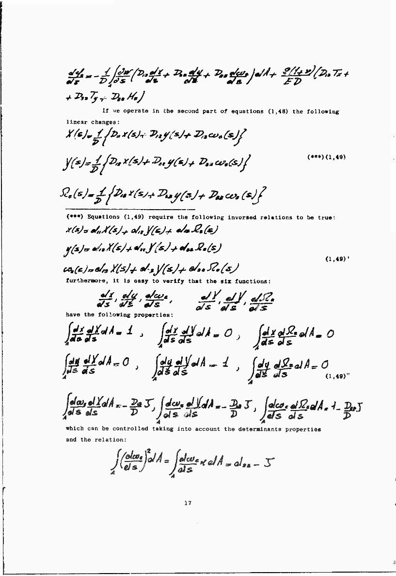
If we operate In the second part of equations (1,48) the following
linear changes:
(*♦*) Equations« (1,49) require the following Invorsed relations to be true;
furthemore, It is easy to verify that the six functions:
js *& irr ' „/s 'irs'ns- have the following properties:
jßg^.l, jß^.O, JggM.O
* 4 'A which can be controlled taking into account the deteralnants properties
and the relation:
17
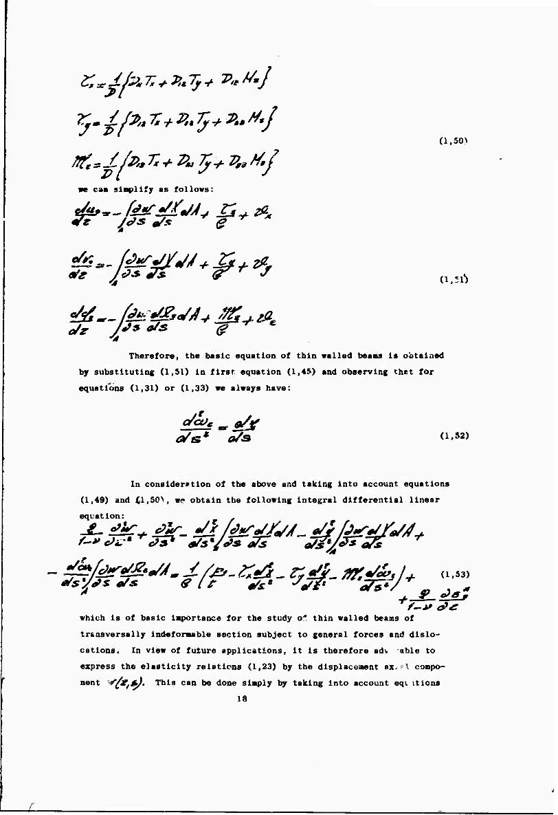
rftK*I/i>,.rx+z>„7}+v,atf,J we cam slnpllfy as follows:
(1,50>
Hß^'g"*' '4
Therefore, the basic equation of thin walled beams is obtained
by substituting (1,51) in first equation (1,45) and observing that for
equations (1,31) or (1,33) we always have:
In consider*tion of the above and taking into account equations
(1,49) and (1,50, wp obtain the following integral differential linear
equation: .
which is of basic importance for the study of thin walled beams of
tr&asversally indefonable section subject to general forces and dislo-
cations. In view of future applications, it is therefore adv able to
express the elasticity relations (1,23) by the displacement ax^pl compo-
nent ^iXffJ' This can be done simply by taking into account eqi itions
18
(1,51); therefore we have;
(1,54)
which are the final «xpresfilooä of elasticity relations for thin walled
beaws. Equation (1,53) «ist furnish solutions satisfying the boundary
conditions on the bases (z = 0 and 2=1) and the transversal conditions
depending upon the sh >e of the bean section described in following
paragraph.
1,7) Boundary conditions connected with basic equation
We divide the boundary conditions into longitudinal conditions,
regarding the external bases z = 0 and z = 1, and tranev«rsal conditions.
In case of longitudinal conditions we notice that, if we con-
sider a body fiee and subject to a system of balanced forces, said con-
ditions rill necessarily impose the equality, in every point, between
external actions p»m and f^im acting respectively on bases
z = 0 and z = 1, and corresponding normal stresses Ssfaf) and ^J/c^s);
therefore, they are as follows:
,i \ (1'55)
<ym[ltsj^ jot.
Equations (1,55, expressed with equations (1 ,;-4) for displacement give:
**0
(1,56)
which represent the two necessary longitudinal conditions to be associated
wi* i basic equation (1,53). We notice that on bases z » 0 and z = 1
the laentity In every point between external actions and Internal stresses
19
concern» onl,- norsal stresses and not shear stresses for which «quations
{1,44} guarantee gxohal identity referred to resulting actions (forces
and aonent).
As far as the end bases ar« concerned, the difference in
every point between external actions fi^mm and internal stresses
"Zffgm is entirely absorbed \rj two existing stiffeners and, consequently,
does not ~ause any additional deforaations or stresses not even In the
areas very clone to the two bases.
Equations (1,56) are therefore tha only longitudinal conditions
concerning the extreae bases.
A different procedure is required for transversal condltiocs,
since they depend upon the type of the cross section. Therefowe, we
will consider ' \ea case by case in regards to the sh ^ of the cross
section directi
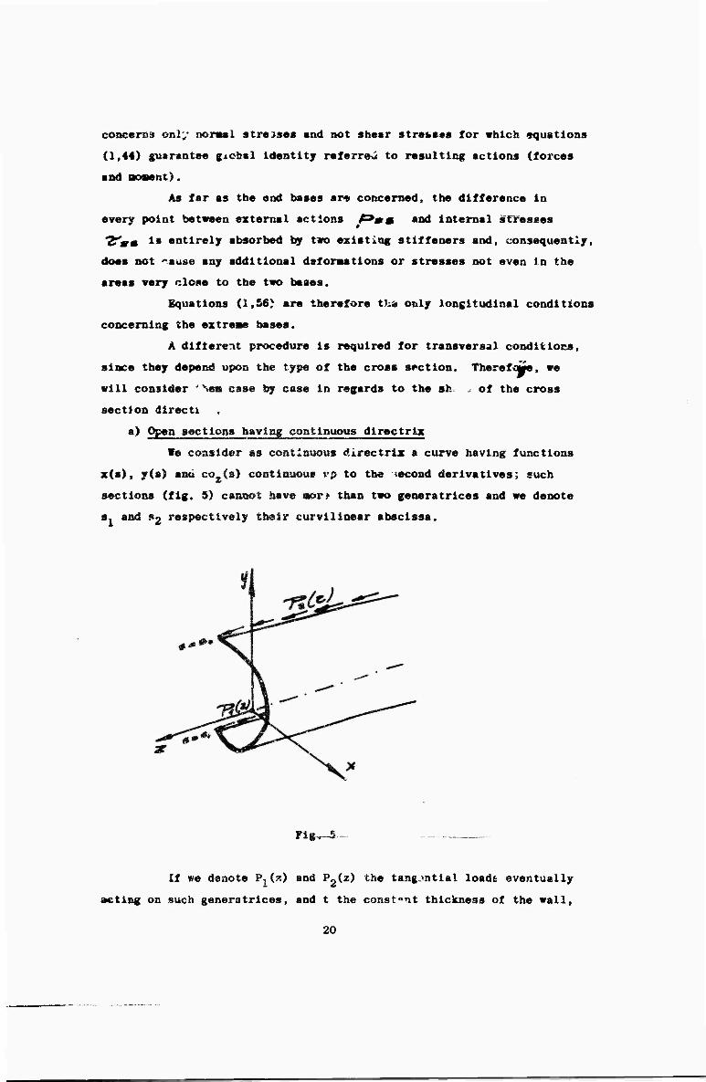
a) Open sections having continuous directrix
We consider as continuous directrix a curve having functions
x(s), y{s) and co (a) continuous i'p to the second derivatives; such
sections (fig. 5) cannot have aor? than two generatrices and we denote
s. and ?2 respectively their curvilinear abscissa.
Flg^-5 -
If we denote PjC?-) and ^2^'t^ the tangential loads eventually
acting on such generatrices, and t the constant thickness of the wall,
20
we can write the transversal conditions as follows:
I*
Taking into account equations (1,54) and denoting L(w) the
term:
(1,58)
'A equations (1,57) can finally be written as follows:
K-U- f^- *-(£)- ZfgJ- »r.*6"J
IM- 7teJ_ ^0J_ r/£j_ nrfr ■y <l,59)a
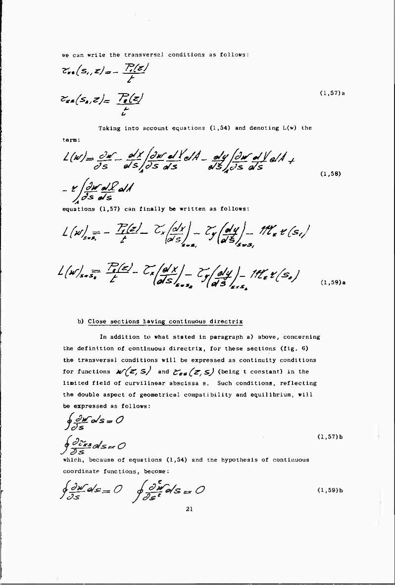
b) Close sections having continuous directrix
In addition to what stated in paragraph a) above, concerning
the definition of continuous directrix, for these sections (fig. 6)
the transversal conditions will be expressed as continuity conditions
for functions Mff^, S/ and CguC^t^J (beinK t constant) in the
limited field of curvilinear abscissa s. Such conditions, reflecting
the double aspect of geometrical compatibility and equilibrium, will
be expressed as follows:
f 0 (l,57)b
which, because of equations (1,54) and the hypothesis of continuous
coordinate functions, become:
££*£*/*=: O I^jTe/s^O (i.59)b
21
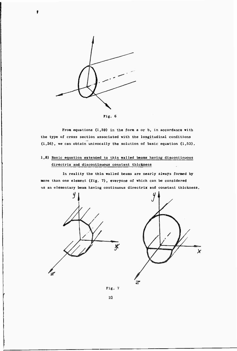
Fig. 6
Fros equations (1,59) In the form a or b, In accordance with
the type of cross section associated with the longitudinal conditions
(1,56), we can obtain unlvocally the solution of basic equation (1,53),
1,8) Basic equation extended to thin walled beams having discontinuous
directrix and discontinuous constant thiclcness
In reality the thin walled beams are nearly always formed by
more than one element (fig. 7), everyone of which can be considered
as an elementary beam having continuous directrix and constant thickness.
Fig. 7
22
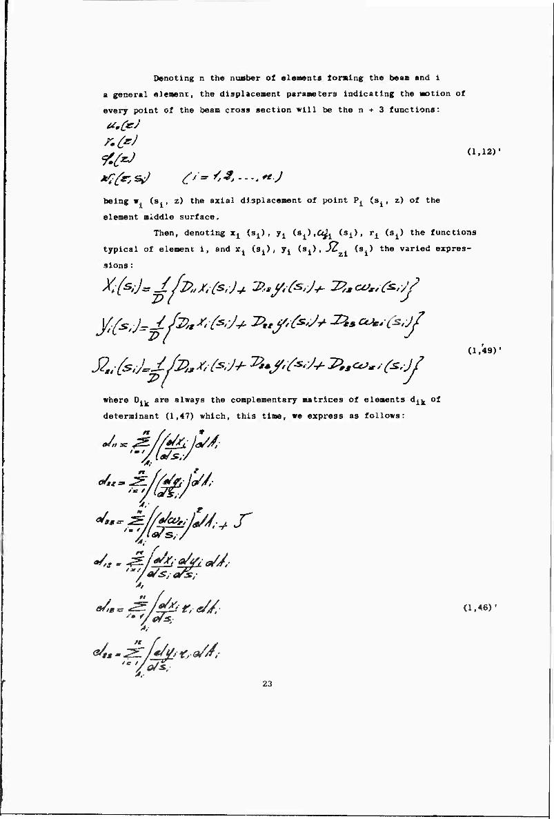
Denoting n the nusber of elements forming the beaa and 1
a general «lemonx, the displacement parameters indicating the Motion of
every point of the beaa cross section will be the n + 3 functions:
9C{*J
being w. (Sj, z) the axial dJsplaceBent of point V^ {a^, z) of the
element »Addle surface.
Then, denoting Xj (Sj) , y^ {B^.O^^ i»i}, ri {s^ the functions
typical of element i, and xi (Sj) , j^ (.3^) , JZ , is^) the varied expres-
sions :
where Dlk are always the complementary matrices of elements d^ of
determinant (1,47) which, this time, we express as follows:
J^^/Mbjl/J.
*»*■
n
(1.49)'
(1,46)'
Ul.- 23
the equations detensimng dispiaceaects Li» , /£ , To , vith expres-
5 sions (1,50) of forces Ox < £ f • /S£K , becoae:
(1.51)'
Therefore, n equations determining displacements w^will be
written as follows:
r* «äST« »<*/ ^v«, ^^ ^'••■/ssrifc '4. ■ ' "
o/** •"/<?*,^£7 eis ^ -t-
(1,55)'
«here tj represents the coistant thickness of eleaeut 1; P ^ (»j) represents
the axial load acting on said element for unit of surface; and *£"*■/
represents the anelastic strain coaponent acting on the same element.
Therefore n + 3 equations formed by (1,51)' and (1,53)' generally
»olve the problem of elastic equilibrium of tbin walled beams, providad
tbat its section has constant discontinuous thickness.
In order to solve said equations we must find the longitudinal
and transversal boundary conditions.
24
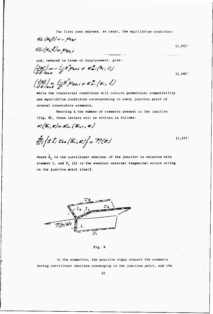
The first ones express, ms usual, the equilibrlun condition:
^'fci/J**/=>*,,; (1.55)
and, reduced In terms of displacement, give:
while the transversal conditions will concern geoiretrical compatibility
and equilibrium conditions corresponding to every junction point of
several consecutive elements.
Denoting k the number of elements present in the junction
(fig. 8), these latters will be written as follows:
(1,56)'
^rfe t, n* fa *jL 7?CrJ (1,57)'
where s. Is the curvilinear abscissi* of the Junction in relation with
eleaent i, and P^ (z) is'the eventual external tangential action acting
on the Junction point itself.
^*-^-« c 3
w
Fig. 8
In the sunanation, the positive signs concern the elements
having curvilinear abscissa converging in the Junction point, and the
25
negativ« OMS concern the r««i»ining eleaents. Therefore, equations
01,57)', written tn tencs •{ dlsplaceaent, give:
and is obvlc^uB the change, if the end of elenent 1 is free rather than
coniMCt*d to other elements.
1,9) Coacluaions
Fro« the study perforaed it aopears clear that the problea of
elastic equilibriun of thin walled beans, considered as cylinders having
transversally indeforaable profile, is acre complicated than what could
be expected following the benas technical theory or the «ore recent Vlasov's
theory of sectorial area.
In fact, the problea can strictly be expressed by an integro-dif-
ferentlal equation linear to the partial derivatives In unknown function
w (z, s), which physically coincides with the axial coaponent of points
displaceaent of aiddle fiber of the wall.
Such equation is not of difficult solution; a general solutioia
will be furnished in the following part of this report, showing how our
solutions are siallar to those obtained by abo/e mentioned approximate
theories and pointing out the unavoidable approxlaation of saae theories.
26
2) STASILITY
2,1) Introduction
tat static behaviour oi & thin walled beaa In regards
rnder appears conspicuous when we study Its equilibriua
te the classic behaviour of the beam subject to combined
SSpresslve stress, which bends In a aaln Inertia plane of
case ot unstabllltj due to axial stress, the thin walled
Ton bends and tvlats at the saae tine under loads uuch
"corresponding to Eulero's fontula.
alllty of having a flexlo-torslonal buckling under
Covered when thin wallevi aeabers of open section
Lrst tlae in designing aeronautic structures: many
I, Ostenfeld [la} , F. ani H. Bleich Qll . «nd
tted the laws governing the phenomenon. Only with
to the more recent studies of Tlmosnenko^Sj and
ther wll^i the works of VlasovflSJ and Goldenweiser
principles have been established: in order to
determine the presence of bending In the beam, the center of gravity
had to Sf^HBRltuted with the center of torsion; only when the axis
of the center of tors'on was rectilinear no flexural energy «as present
in the thin walled members; and, furthermore, the warping rigidity C^
was exactly formulated.
Of greet Importance are the studies performed by Vlasov [iSj
for the formulation of a theory concerni.-jg the unstability of the thin
walled beam of open section subject to normal, bending and shearing
stresses, and the studies performed by Krall 1,17j, who obtains the stabi-
lity equations by using the variation*! approach with the introduction
of the twisting moment and considering various cases of combined unsta-
bility.
The constent progress of technics led to an always wider
application of the thin walled beams; this structural element Is now
present in most civil and industrial, naval, aeronautic and space
constructions!
Therefore, the study of equilibrium stabi Ity of a thin walled
beam of open section is always of great interest and new problems arise:
as, for instance, the basic one concerning the Influence of the dislocation
on the stability, its effect and the effect of external cor.bervatlve and
27
conconsorvative forces on the dynaalcs, etc.
Thus, we want to ezaalne again the whole systea of elastic
equilibriua stability of the thin walled beaa subject to general
loading and dislocation and we try to set up P new general theory.
The study of such beams, as conducted in the first part of
this report and connected with researches underlay, the results of which
will be furnished in a later report, confirm the validity of sectorial
areas theory without consideration of local effects connected to the
presence of concentrated forces, holes, etc.
Thus, making use of Vlasov's static theory, staple and suffi-
ciently correct for an invest'gation on such phenomena, we obtain, in
accordance with dynamic method, and using a geometric systeuatic pro-
cedure, the basic differential equations governing the stahility problem
of the beam motion under generally distributed conservati 9 forces and
dislocations. Sisc.- equations are expressed by the load'i itrectly applied
and the stress conponents corresponding to the bas c ^o/i'lguratioi? and
includes four functions characterizing the flexural, ton ional «no
eztensional oscillations respectively. The eztensional ->scillatimt is
often neglected, but is interesting because of Its stabilizing effects.
The systom of forces F0 (x y z) acting on the tain walled beam
is formed by distributed forces Q0 (z, s); Q0 (z, s); Q0 (z, s), which x y z
have the same direction of axes x, y, z, and are functic.is of curvilinear
abscissa s formed by the center line of the cross section. Such forces
are conservative and keep their direction during the displacement of
the points at which they are applied and generally originate a distri-
bution of transversal forces p0 (z) and p0 (z), axial forces p0 (z),
bending couples m0^ (z) and *P (z), twisting couples m0z (z), and
blmoments 0° (z).
The dislocations system ^ (x y z) causes a stress condition
which can be annulled, generally, only by dividing the body into its
elementary particles or, raore simply, by cutting it into a finite number
of planes. The introduction of the dislocations system Q (x y z) will
be useful later for the study of the unstabilizing effects caused by
residual stresses, non uniform thermic field or prestresslng systems.
2,2) General remarks on approach ■ethod
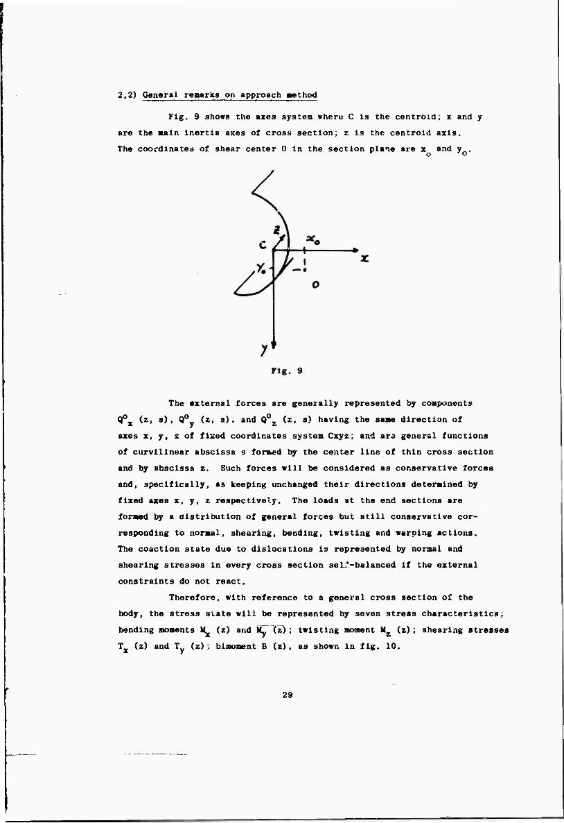
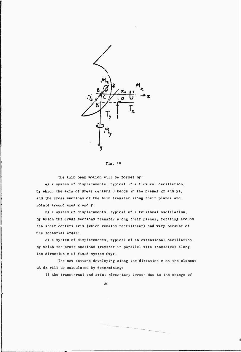
Fig. 9 shows the axes system where C Is the centroid; x and y
are the Bain inertia axes of cross section; z is the centroid axis.
The coordinate!* of shear center 0 in the section plane are x and y .
The external forces are generally represented by components
Q0_ (z, s), Q0„ (z, s). and Q0_ (z, s) having the sane direction of x y z
axes x, y, z of fixed coordinates system Cxyz; and ara general functions
of curvilinear abscissa s formed by the center line of thin cross section
and by abscissa z. Such forces will be considered as conservative forces
and, specifically, as keeping unchanged their directions determined by
fixed axes x, y, z respectively. The loads at the end sections are
formed by a distribution of general forces but still conservative cor-
responding to normal, sheering, bending, twisting and warping actions.
The coaction state due to dislocations is represented by normal and
shearing stresses in every cross section selZ-balanced if the external
constraints do not react.
Therefore, with reference to a general cross section of the
body, the stress state will be represented by seven stress characteristics;
bending moments M (z) and My (z); twisting moment M (z); shearing stresses
Tx (z) and T (z); blmoment B (z), as shown in fig. 10.
29
Mxy
ntMj/,'oü **
7;
n.
Fig. 10
The thin beam aotlon will be tormei by:
a) a syätea of displaceaents, typical ,f a flexural oscillation,
by which the axis of shear centers 0 bends in the planes xz and yz,
and the cross sections of the be^m transfer along their planes and
rotate around axes x and y;
b) a system of displacements, typical of a toisional oscillation,
by which the cross sections transfer along their planes, rotating around
the shear centers axis (which remains rectilinear) and warp because of
the sectorlal ar«as;
c) a system of displacements, typical of an extensional oscillation,
by which the cross sections transfer in parallel with themselves along
the direction z of fixed system Cxyz.
The new actions developing along the direction z on the element
dA dz will be calculated by determining:
1) the transversal and axial elementary forces due to the change of
30
direction of stresses f cjA , V (i/\ , 9 4A , folio»*ng the
fibers buckling;
2) the eleaentary couples, which «e call "turnover" couple?, causing
the rotation of eleaent dA dz around fixed axes x »nd y and z ni6 due
to the coaponents along axes x, y, z of fixed syst«B of eleaentary forces
V 4A , V (JA t <r dA . »ctlng on the buckled body;
3) the eleaentary couples, which we call "displaceaent" couples, due
to the fact that forces tr ejtf , "XT dA , G" dA > acting on the
two sides dA of eleaent dA dz and the surface forces Q ($4)dd. Q (zt-i) d^,
^jV-^/Sj^-iJ , during the buckling, assuae a different position in regards
of fixed referenced systea.
Further, we calculate the actions which, because of the degree
of freedom of cross section, are consequent on the previous ones; in this
Banner torques distributed on z will be associated to a transversal eleaen-
tary load, and bending couples and biaoaents will be associated to axial
actions. The determination of inertia forces will complete the calculation
of the actions caused by iaposed displacements.
Such procedure is sistematically used for the flexural, torsional
and extensional oscillations and permits to formulate the general equations
expressing the motion of the thin walled be" in general as well as taking
into account the unstabilizing effects of stresses (correapor-ding to the
basic position of the beam) and of tne surface loads.
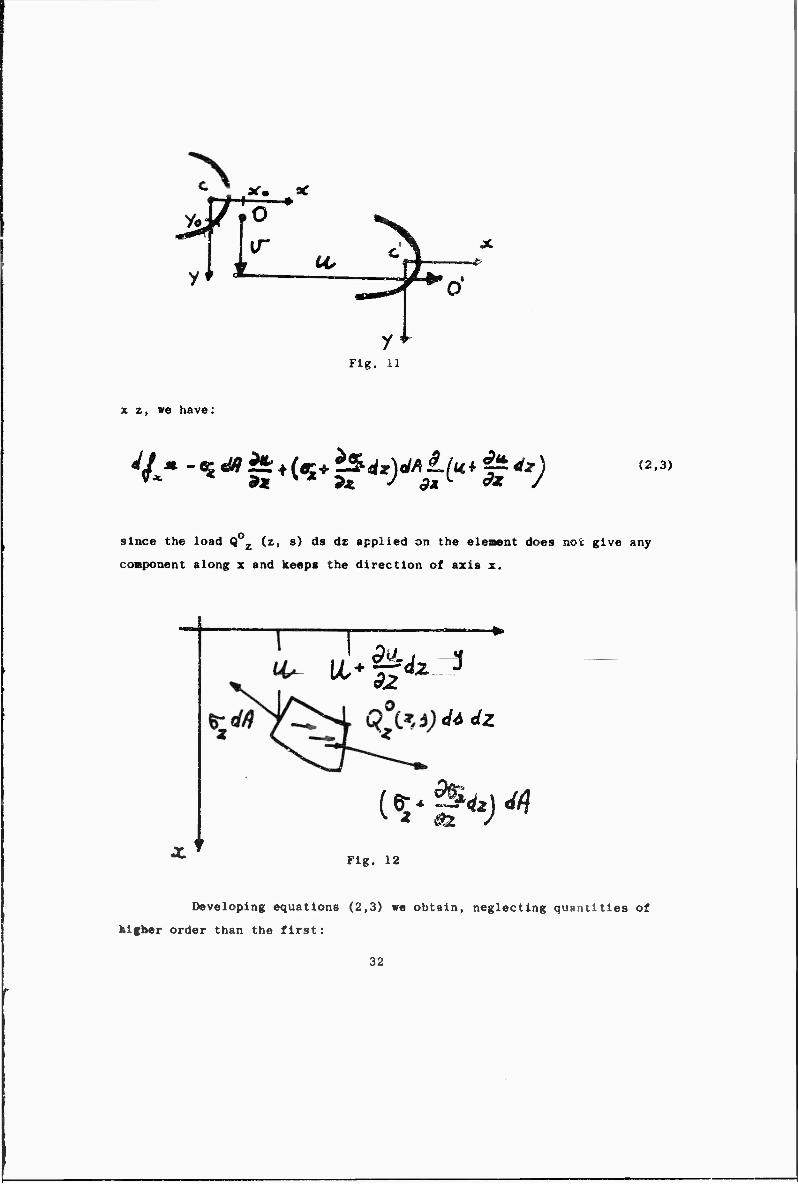
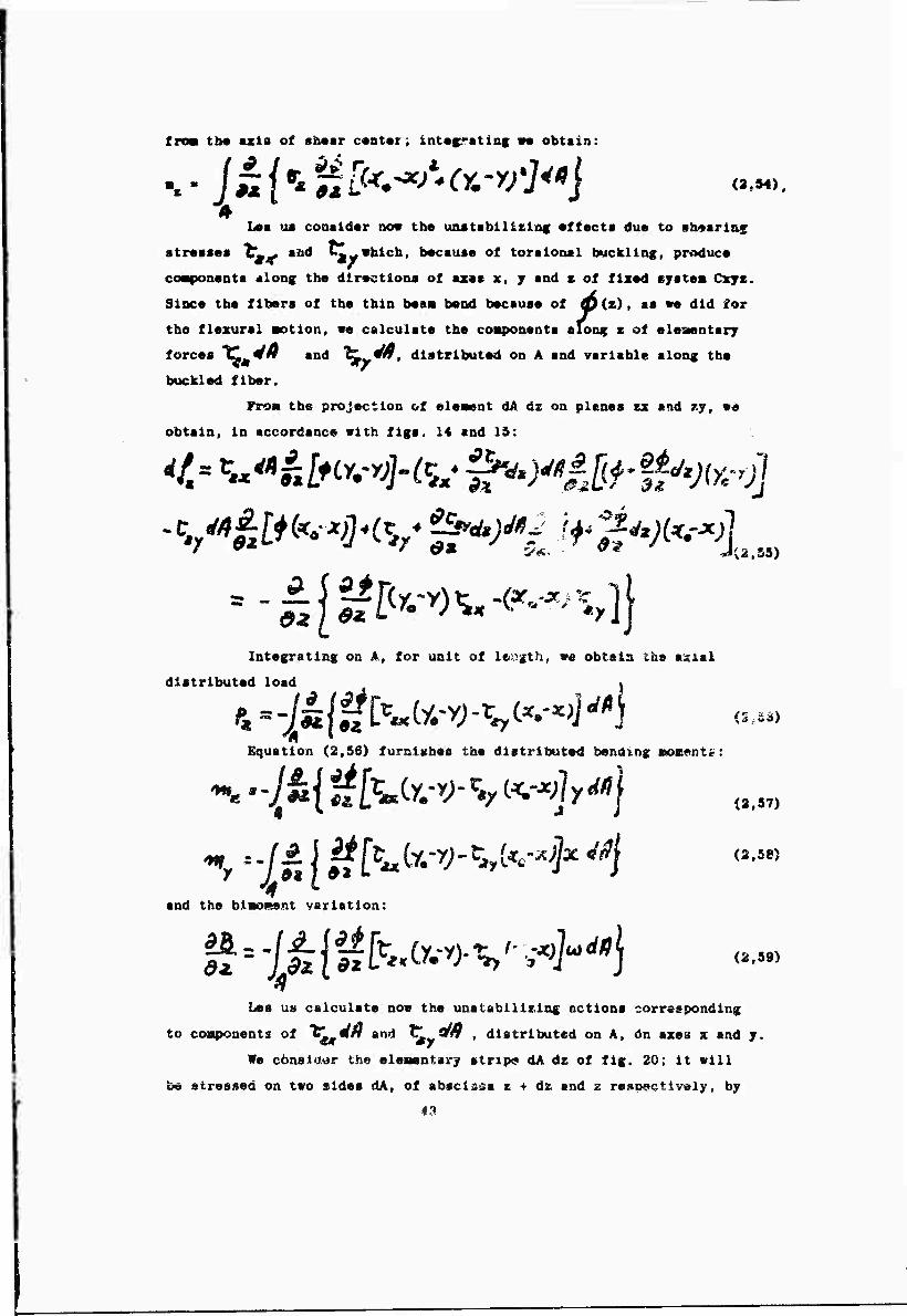
2,3) Effects due to flexural motion
Let us consider the flexural deformation. It is characterized
(fig. 11) b/ displacement coaponents:
u (z, t) ; v (z, t) (2',i)
of the line of shear centers 0; and, for the rotation of sections around
axes x and y, by the displaceaent component along axis z.
i Bu. £?(/■ (2,2)
We consider, above all, the unstabilizing effects due to stresses
and we calculate, along axis x of fixed system Cxyz, the components
df of the elementary forces ac.ing on the elementary buckled stripe dA dz
of the beam pertaining to two cross sections at the distance dz. With
reference to fig. 12, representing . e projection of dA dz on the plane
31
j#r° *m *
i 14, C|4~ * ^—-^^v y
Fig. 11
x z, we have;
v.- -«s^^^^^n^41"; (2,3)
since the load Q z (z, s) ds dz applied on the element does not give any
component along x and keeps the direction of axis x.
ul-t^ <l4dZ
(*■*&<*)«
Fig. 12
Developing equations (2,3) we obtain, neglecting quantities of
higher order than the first:
32
As (2,4)
In this manner, for unit of length, we heve the cross elementary load:
^=f(«i^; (2.5)
Correspondingly, we have the elementary moment dMy, due to the
nts or #1 On aion compone
around axis y; it is:
g x which tends to turn over the element dA dz
iny--^f^ (2.6)
in this manner, for unit of length, we have the elewentary distributed
moment:
**> "- ^ dz and, for the whole section
^ - -//* t ^
(2,6/)
(2,7)
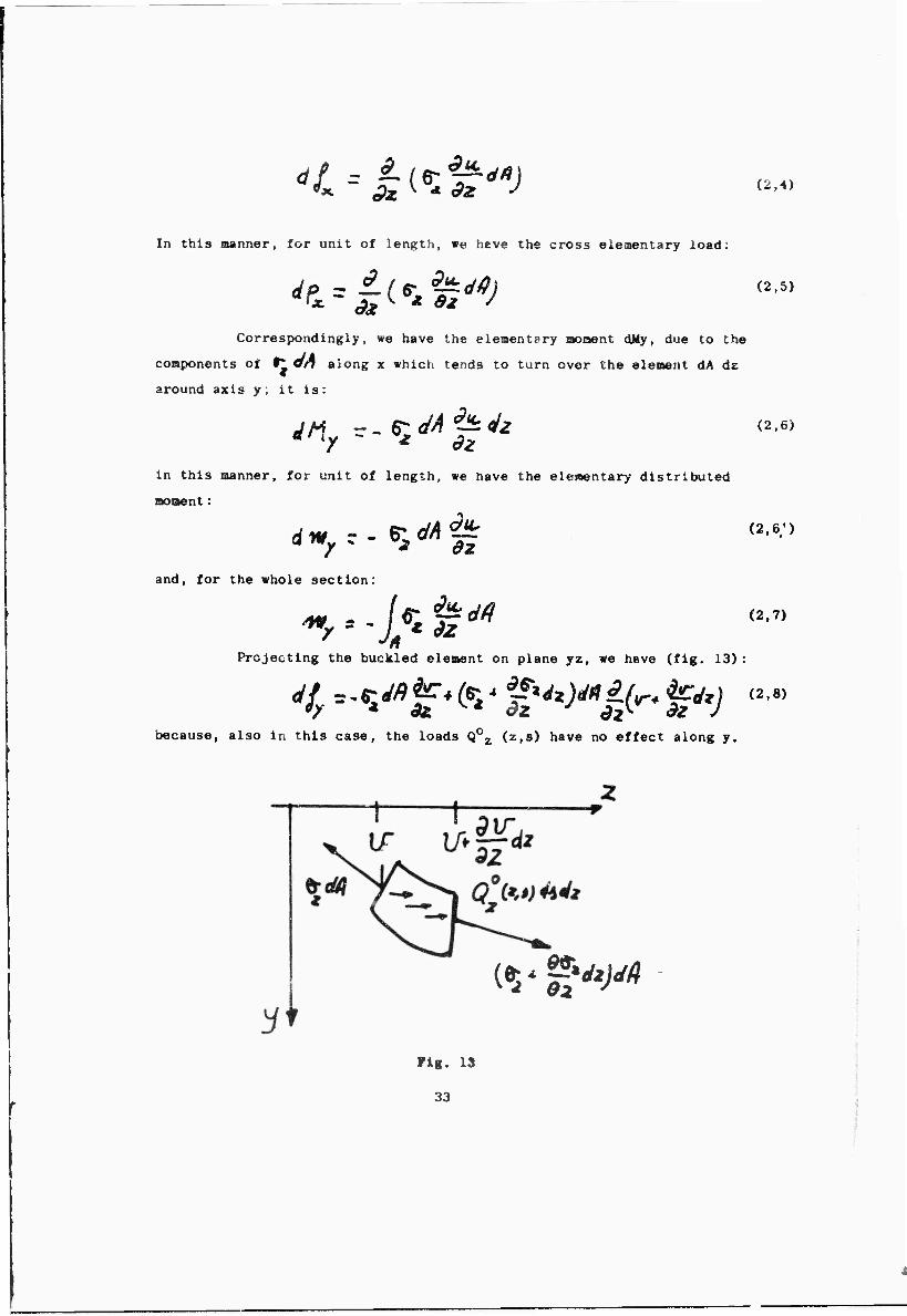
Projecting the buckled element on plan© yz, we heve (fig. 13):
because, also in this case, the loads Q0Z (z,s) have no effect along y.
(Vs**^
Fig. 13
33
L«cveioping equation (2,6) we obtain, for unit of length:
■^ = is (^ If ^ In the same nanner as f<r equation (2,6), we have the nsoment :
dH z-tlJfiiZdZ (2,10) cendlng to turn over the element dA dz around axis x; for unit of length,
me have the eleoentary distribution moment:
a/*C--«:^|^ (2,io')
and, for the whole section:
-If S 'Mt,*-] "* Si4" (2,1»
Integrating equations (2,5) and (2,9) en the transversal area,
we have the new distributed actions due to the fact that, in buckled
condition, normal stresses 6^ lean forward forming variable angles in
regards to the original direction of z axis.
Thus we have:
Equations (2,5) and (2,9) give the transversal load due t:> the
flerural buckling of the elementary stripe dA dz; consequently, we have
the following twisting elementary moment distributed along z: llowing twisting elementary moment distributed along z:
the symbols of fig. 13 which shows as positive the twisting
(2,13)
using the symbols of fig. 13 which shows as positive the twisting moment
(or the angle 4 ) if its direction of rotation Is the same bringing a?.!.
x on axis y.
Integrating on the whole cross section A we obtain:
*r-IU**%cw-**&''-*jy* (2,14)
Equations (2,8) and (2,10) are always valid if the loads Q0 (z.s)
keep the same direction of axis z of fixed system Cxyz. Let us consider
now the effects of shearing stresses t' and ^.w acting on the transversal
sides dA of the elementary buckled stripe.
With reference to fig. 14, showing the projection of element dA dz
on plane x, z, we calculate the components along z of elementary forces
34
cv-^
Fig. 14
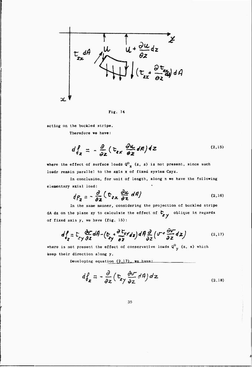
acting on the buckled stripe.
Therefore we have:
du. (2,15)
where the effect of surface loads Q0 (z, s) is not present, since such
loads remain parallel to the axis x of fixed system Cxyz.
In conclusion, for unit of length, along z we have the following
elementary axial load: '
In the same manner, considering the projection of buckled stripe
dA dz on the plane zy to calculate the effect of d, , oblique in regards
of fixed axis y, we have (fig. 15) :
where is not present the effect of conservative loads Q0 (z, s) which
keep their direction along y.
Developing equation (2.17), wa have:
(2,17)
dsr (2.18)
35
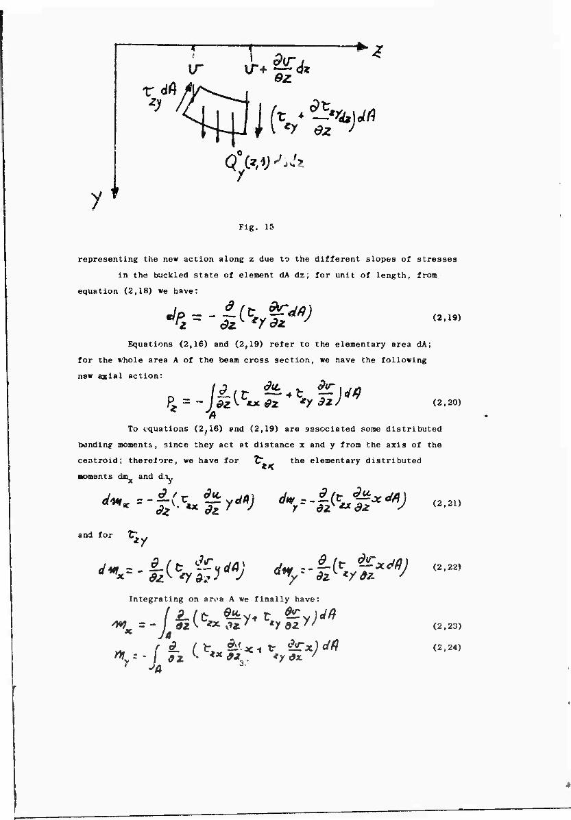
y*
[T
9
9ir j
'^Jfv^ M
Qi'.V^
Fig. 15
representing the new action along z due to the different slopes of stresses
in the buckled state of element dA dz; for unit of length, from
equation (2,18) we have:
Jp^-f^y&V dfc' */#* (2,19)
Equations (2f16) and (2,19) refer to the elementary area dA;
for the whole area A of the beaa cross section, we nave the following
new axial action:
^ (2,20)
To equations (2,16) »nd (2,19) are sssociated some distributed
bending moments, since they act at distance x and y from the axis of the
centroid; therefore, we have for
moments din and d.u^
9 f -r- du.
** the elementary distributed
'*« -i(^i yv dwr -§■&£*d*) and for
Integrating on arv>a A we finally have:
^y- - / tz ^ *X*J3C *?**■ '
(2,21)
(2,22)
(2,23)
(2,24)
Turthernore, equation (2,16) gives tlie blmoment variation:
(2,25)
Equations (2,7), (.>311), (2.12). (2,14), (2,20). (2,23).
(2,24), and (2,25) represent the new actions due to the variable slopes
of normal and shearing stresses in the buckled stac?, but it is essential
to notice that in such condition the forces acting on the element have
a different position if ccmp?r(;d to the fixed axis Cxyz. Obviously, this
changes the stresses field in the body; in order to calculate this effect
it will be sufficient to refer to the elementary stripe JA dz and consider
the moments, relative to the forces acting on two sides dA as well as
those actir-j on lateral surface of dA dz, due to the displacement of
such forces freu basic position to the displaced one.
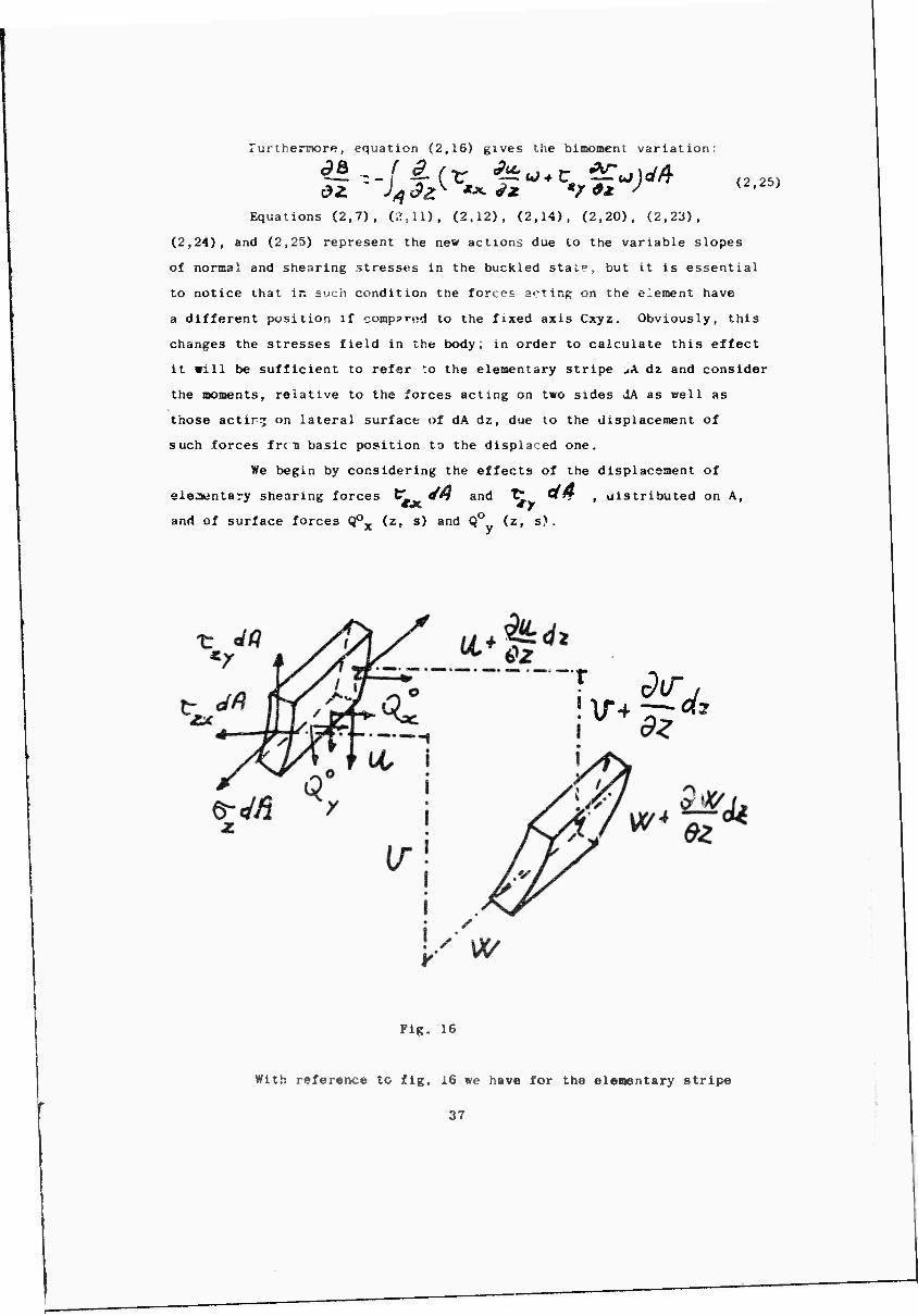
We begin by considering the effects of the displacement of
elementary shearing forces C^ QH and T" Üff , ulstributed on A,
and of surface forces Q0Y (z, s) and Q0 (z, s). * y
7 ^«o
Fig, 16
With reference to fig. 16 we have for the elementary stripe
3 7
dA dz the following change of twisting aoment:
(2,26)
Integrating on area A and on center line s of the cross section,
we obtain for unit of length:
4 JA JS Ji Also because of the rotation of cross sections around axes
x and y, the elementary internal forces ^ **f , "C^ dfj and the
external surface loads 0°^ (z, s) aod Q0 (z, s) move their points of
application of quantity:
With the sane procedure previously used, we obtain the following
distributed elementary bending couples:
(2,28)
(2,30)
integrating en A and s we finally have:
* i (2,31)
(2,32)
S
38
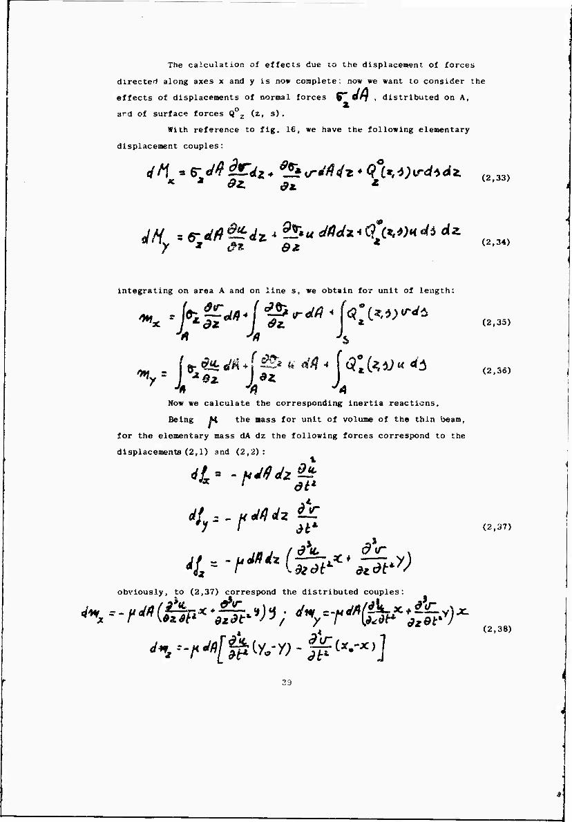
The calculation of effects due to the displacement of forces
directed along axes x and y is no* complete; now we want to consider the
effects of displacements of normal forces ^ Orf , distributed on A,
ard of surface forces Q z (z, s).
With reference to fig, 16, we have the following elementary
displacement couples:
«r-r
x.
(2,33)
(2,36)
4H -.e-M^dz'-'uM^tO***4*** (234)
integrating on area A and on line s, we obtain for unit of length:
™X. I t-dZ** I <9Z. «V (2.35)
Now we calculate the corresponding inertia reactions.
Being M the mass for unit of volume of the thin beam,
for the elementary mass dA dz the following forces correspond to the
displacements (2,1) and (2,2):
* ' at1
Ji* (2,37)
obviously, to (2,37) correspond the distributed couples:
(2,38)
Integrating on the whole section ee obtain the following action«
/>,--/"» ft'- r* = ° for unit of length:
On the contrary, the blaoaent which seems to develop from (2,37)
eqaals zero; in fact, we have: .
(2,39)
2,40)
(2,41)
because the sectorial coordinate t«j is orthogonal to the coordinates
x and y.
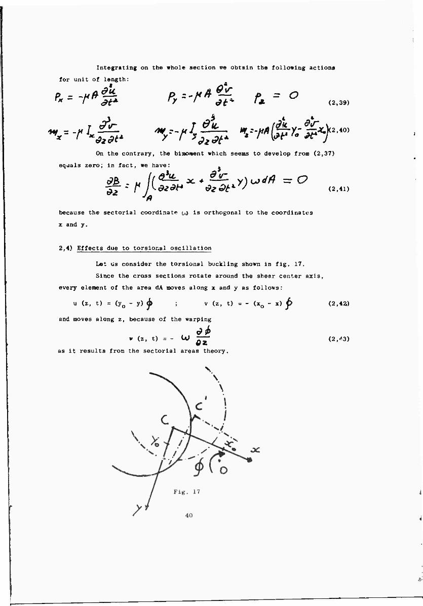
2,4) Effects due to torslonal oscillation
Let us consider the torsional buckling shown in fig, 17.
Since the cross sections rotate around the shear center asls,
every element of the area dA moves along x and y as follows:
u (z, t) = (y0 - y) ^ (z, t) = - (x0 - x) p
and moves along z, because of the warping
(z, t) = - U» 62
(2,4a)
(2,^3)
as it results from the sectorial areas theory.
The angle (fe , together with the twisting nonent Mz, is
therefore considered positive i± it brings x on y, being z downward.
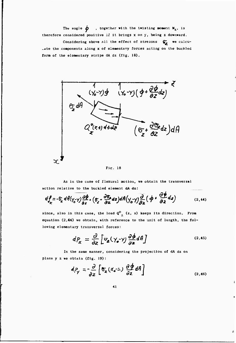
Considering above ^11 the effect of stresses g^ we calcu-
.dte the components along x of elenentary forces acting on the buckled
form of the elementary stripe dA dz (fig. 18).
x'
T T cye-y)i oi-y)C^ w<fc;
,9- 9% (vf^J^
Fii^. 18
As in the case of flexural motion, wa obtain the transversal
action relative to the buckled element dA dz:
(2,44)
since, also in this case, the load Q0^ (z, s) keeps its direction. From
equation (2,44) we obtain, with reference to the unit of length, the fol-
lowing elementary transversal forces:
<*& = & h^-v U^J (2.45)
In the same manner, considering the projection of dA dz on
plane y z we obtain (fig. 19):
4V -i [w; gat] (2,46)
41
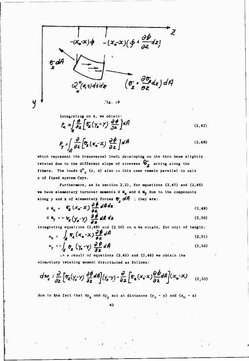
~1—-7 —
(tr*^)M ez
r .'ig. i9
Integrating on A, »e obtain:
(2,47)
(2,«8)
which represent the transversal load» developing on the thin beam slightly
twisted due to the different slope of stresses P. act iig along the
fibers. The loads Q (z, s) also in this case remain parallel to axis
z of fixed system Cxyz.
Furthenaore, as in section 2,2), for equations (2,45) and (2,46)
we have eleaentary turnover soaents d VL and d My due to the components
along y and x of elementary forces fr &ft ; they are;
<.«.. «;w.-«j^^A (2.49)
jrating equations (2,49) cud
(2,50)
integrating equations (2,49) end (2-50) on A we obtain, for unit of length:
#Ä <2'51>
(2,52) '4 '* ''* V #; sä a result of equations (2,45) and (2,46) we obtain the
eloi&cmtary twisting moment distributed as follows;
üb. * -Wvt^^ <2.53) due to the fact that dp and dp act at distances (y0 - y) and (x0 - x)
42
fro« tba axis of nhmtr center; int«gr«tiaf *• obtain:
Las um coasldor now the unstabilisiag effects due to «bearing
streasea l^-» aad C^ which, because of toraional buckling, produce
coaponenta along the directions of axes x, j and x of fixed ejratee Cxfz.
Since the fibera of the thin beae bend because of (piz), aa we did for
the flezural aotion, we calculate the coaponenta along z of eleaentarjr
forces H^jglt* *nd ^>y*", distributed on A and variable along the
buckled fiber.
Froa the projection of eleaent dA dz on planea zx and zyt we
obtain, in accordance with figa. 14 and 15:
Integrating on A, for unit of length, we obtain the axial
distributed load •
Equation (2r56) furnlshos th« diftriöut#d bending vonent^:
(S.ää)
'M'«* /•»/#* L'ÄV^ V •y-* 'll~'l (2 57)
(2,58)
and the blaoieent variation:
Lea ua calculate now the unatabllizing cctiona corresponding;
to coapoüents of tT^dn and ^y**" . distributed on A, on axes x and y.
We cönsitldr the elesentarjr »tripe dA dz of fig. 20; it will
be stressed on two sides dA, of abscissa z •«■ dz and z respectively, by
43
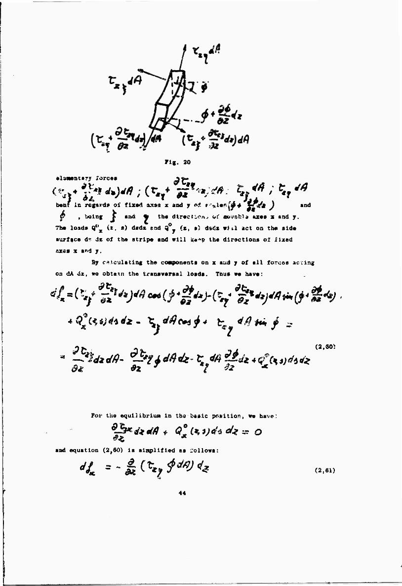
•Isatntarj Xorcsi
Flg. 20
b»nt in regsrd? ol flx«d «« x sad y o* r-*l*fu'4+ *^t )
^ , fcolng ^
^
and
■a4 * th« flirtet ten* iti aojstl* uc«e x and y. • P 7b« load» Q*^ {«, e) dsds" cod 9"y («, •> <l6<!s vtil act on the aid«
aurffce d" de of th« strip« and «111 *»»c tb« directions of xixed
ex«B z and y.
By c^iculatinc tb« coavonents on z aud y of all forces seeing
on dA «ix, v« obtain th« transv«r«al loads. Thus wo bav«:
* <?'« tjto a* . t dtic* j 4 t 4.(1 M / ^
Pfc L ^ J/ (2.80>
For the equlUbrlu« in th» basic pf-iiitio», w« bav«:
aad «quatlon (2,60) is »iaplift®d as follows:
^ =~ii^f*'V4* (2,61)
44
r9pr«**ntlaff the new tranavaraal force«, distributed on dz and directed
alone x, da« to the new slope of shearing atress«s after buckling; for
unit of length, we have:
being t^y r Vt~ .
In th« Maea Bannerc performing a projection along y, we obtain
the cleaentarj transversal forces directed aloug y and relative to the
length dz of eleeent dA dz;
ö> f
= *t%J <**)<'* being, for the equilibria* along the direction j in the basic condition
For unit of length, we have:
Integrating equations (2,62) and (2,S5) op the area A of cross
section, we obtain the transversal leads:
^ - LftC*~W (2,67)
4#
produce the following turnove;. couples around ST^S S and f
Purtheraor?, the coapoasü.s al^ng z and 7 of fev^ and
•tä
(».«t)
Iat«gratinc oo A, v* obtain, for unit of length:
Vnm «Mjuatlon« 12,62) mad (2,65) «• obtain tha di«trlbu;ed
aiaaaatary tolttlng
(2,70)
(2,71)
/« # #» (2,72)
whichj by Integration on area A, we have:
•if M In this aannar va have calculated tha new action» davaleplng
along abaciasa z of the thin walled baaa In a slightly buckled for« doa
to th* variable alopaa of the atraaaaa. For tha calculation of auch
actions we did not conaldar tha warping of th« croaa section, baeausa
it causaa only a variation of ganaratrlcaa length and not their bending;
4n the contrary, h* shown later, it will affect tha calculation of
rMspliceaent aoaenta.
For the calculation of such displacaaent aoaeuts, we consider
that, tecaua« of diaplacaaanti«
« - (Fo " y> ^ ' v « - (^ - x) ^
th« »b< «ilng atresses 1^- and ^^ «nd the aurface loads Q0 and
Q0 laoved along y and z resoactiv«ly; thus we have, as in equation
(2,27>K the eleaentar; distributed twisting soakants:
* /
froa which, integrating on A, we obtain
(2,74)
^Jhi^^-'^y^'-^} + (2,75)
46
Let uc coocider no* tbc warplox of cross «ection ot positiv«
aectori«! coordlv^st«; bocaus« of this warplocvhicb varlss tlonj; z
with O/ , the shearing stresses ^H an<t ^Oy aad tiM surface loads
Q0 (z, s) ssd Q0 (s, s) ■wve In parallel with tbeaselves; In the sas«
■anner a» for equations (2,31) and (3,32), we have the distributed
bending couples: ag couples: - ,. «
(2,76)
«P^
No« «e calculate »he effect of -its' i«ce»»nt of noraal stresses
ftr, and of surface loads Q0_ (z, a).
As for equations (2,33) and (2,34) we have the dispi«ce«ent
eleaentary couples:
(2.78)
*nr' *%*"^r. y)&** $z *-* * (2.7»)
fro« which, by lutagv^ting on A, we obtaiu:
* J4 ** 4 4 <2,80)
%* kLysy)l*M*j*£^yJ^fö^^ $ ^ & (3,81)
fto* «® Cbiculale the inertia forces appearing during the
to!sioaal aotlon.
*lth reference to w!o»e-atary auss dA A», we have the eleweotsrjr
force;/ ■
U I fit fit* correspondingly, we have the elementary couples:
ill
(2,82)
(2,83)
Equations (2,82) and (2,83) give the cross and axial distributed
forces:
(2,84)
and the couples:
/T^^O ^=0 *Ü=r^5F (2.85) while the components dfz give the binoaent variation:
tl- t41* 575?* (2'86)
being J^ and J-^ the quantities:
polar moaent of the cross section in regards of the shear center 0 and
sectorial Boment, respectively.
2,5) Effects due to extensional oscillation
Let us consider the extensional oscillation.
Since the sections have only displa. aents w(z) along
(fig. 21), in the extensional buckling we do not hawe variable slopes
of stresses, in regards of axes x, y and z, a&w corresponding unstabl-
liring effects do not appear. On the contrary, we notice soae ucstabi-
lizing effects beouusio, due lu the extensional dlsplaceaent w, variable
45
with z, the «haarliig stresses tL sad C^w and tbe loads Q0X (s. s)
and Q0y (z, s) aove In parallel with themselves. So w* have the bendtn«
distributed couples:
(2,88)
(2.89)
W
Fig. 21
p^ = 0
s^
Tbe inertia forces are given by:
Py-0 Pz —^
s ■ s B s 0
(2,90),
(2s9i)
IÄ««9((p^'
49
2.*J §£BSt£J oquatlc-na of dyn«»ica of thin walled beams
In paragraphs 2,2), 2,3) and 2,4) above we calculated the actions
devfflosti»j; on the thin vailed beaK during It? dleplacenent caused by
flMUral, toralonal and extenslonal buckling. They are alvaya balanced
with rim elastic reactions and the loads directly applied; If we approzl-
M»oe tSe curvatures In the planes xz and yz to th© curvatures in j^
»nd y\ , we will obtain the following differential equations systes:
+Jf<£(y.-o-<?;(*.^ ^S''*''4
Abov« sjftes, togethor »1th the boundary and Initial condition»,
furaisb«« th« action of th« b«as under (F0) and (Ä*) ; these lattara ar«
represented directly by distributed load« Q0X (z, •), Q (z, a) and
Q0r (z, ■> and indirectly by stresse» coaponent« ^ , t^ , V^y ,
corresponding to the basic equilibrium condition.
As far as stability Is concerned, It Is Interesting to d-teralne
the value of the aultlpller /k. of (1°) and < ^*) for which the aotlon
Is no jore liaitBd;JEi9uch case of conservative forcea and dislocations
the change froa stability to unstablllty will be expressed by the value
zero of the aotlon frequency.
Above systea (2.93) also includes all the problems of stability
and dynaaics of thin walled beaa of close section and of the solid section
beaa and can be easily applied to the various particular canes, expressing
f roa tiae to tlae the applied loads and the stresse» component« 4L , tl ty^,-
51
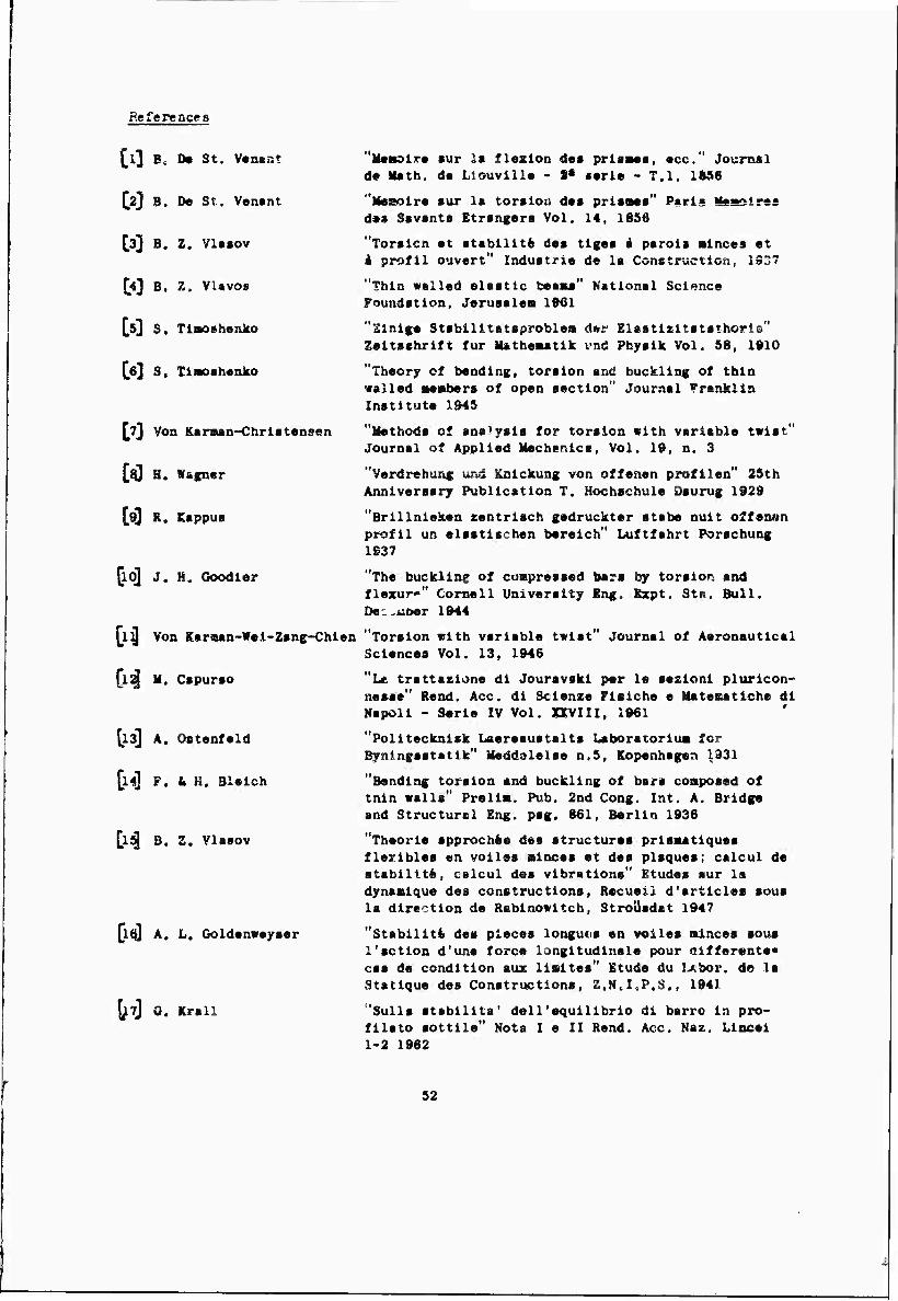
References
£l3 Bs Do St. V«n»r.t
[2} B. De St. V»n«nt
^3] B. Z. Vlttov
£0 B. Z, VUvos
^53 S. Tiaoshonko
[ei] S. IliK>sh«ako
^TJ Von KarB«n-Chrl«t«nsen
[{Q H. Wagner
[93 R. Eappus
[id] J. H, Goodler
\l^ Von Karaen-Wcl-Zans-Chien
[i2| M. Capurao
[133 A. Oatanfeld
[l4] F. k H. Bleich
[l5J B. Z, Vlaaov
[1(0 A, L. Goldenweyaer
u Q. Krall
"Uesslre aur la flexion dea prlaaea, ecc." Journal de Math, de Liouville - S* aerie - T.l, 1856
"Meaoire aur la toraion dea prlaaea" Parts Msasires des Savants Etrangera Vol. 14, 1856
"Toralcn et atabilltfc dea tigea i parola ainces et i prof11 ouvert" Industrie de la Construction. iS37
"Thin walled elastic heaaui" National Science Foundation, Jerusalem 1931
"Einige Stabllltetsproblea der Elastisltatsthoris" Zeitschrift fur Matheaatik vnd Physik Vol. 58, 1910
"Theory of bending, torsion and buckling of thin walled Mtabers of open section" Journal Franklin Institute X945
"Methods of analysis for torsion with variable twist" Journal of Applied Mechanics, Vol. 19, n. 3
"Verdrehung und Knickung von offenen profilen" 2Sth Anniversary Publication T. Hochschule Daurug 1929
"Brillnieken zentrisch gedruckter stabe nuit o2fenon Profil un claatischen bereich" Luftfahrt Porachung 1937
"The buckling of compressed bars by torsion and flezuro" Cornell University Eng. Ezpt. Ste. Bull. De „-.oer 1944
"Torsion with variable twist" Journal of Aeronautical Sciences Vol. 13, 1946
"Lc trattazione di Jouravski per le aezionl pluricon- nesse" Rend. Ace. di Scienze Fisiche e Matesatiche di Napoli - Serie IV Vol. XXVIII, 1961
"Politecknisk Laereaustalta Laboratorium for Bynlngsstatlk" Meddelelse n.5, Kopenhagen \d31
"Bending torsion and buckling of bar« composed of tnin walls" Prelim. Pub. 2nd Cong. Int. A. Bridge and Structural Eng. pag. 861, Berlin 1936
"Theorie approchfce des structures prismatiques flexibles en voiles minces et des plaques; calcul de stability, calcul des vibrations" Etudes sur la dynamique des constructions, Recueil d'articles sous la direction de Rabinowitch, Strolisdat 1947
"Stability des pieces longuns en voiles minces sous 1'action d'une force longitudinale pour aifferente« cas de condition aux limites" Etude du Ixbor. de la Statlque des Constructions, Z.N.I.P.S., 1941
'Sulla atabilita' dell'equillbrio di barro in pro- filato sottile" Nota I e II Rend. Ace. Naz. Lincei 1-2 1962
52
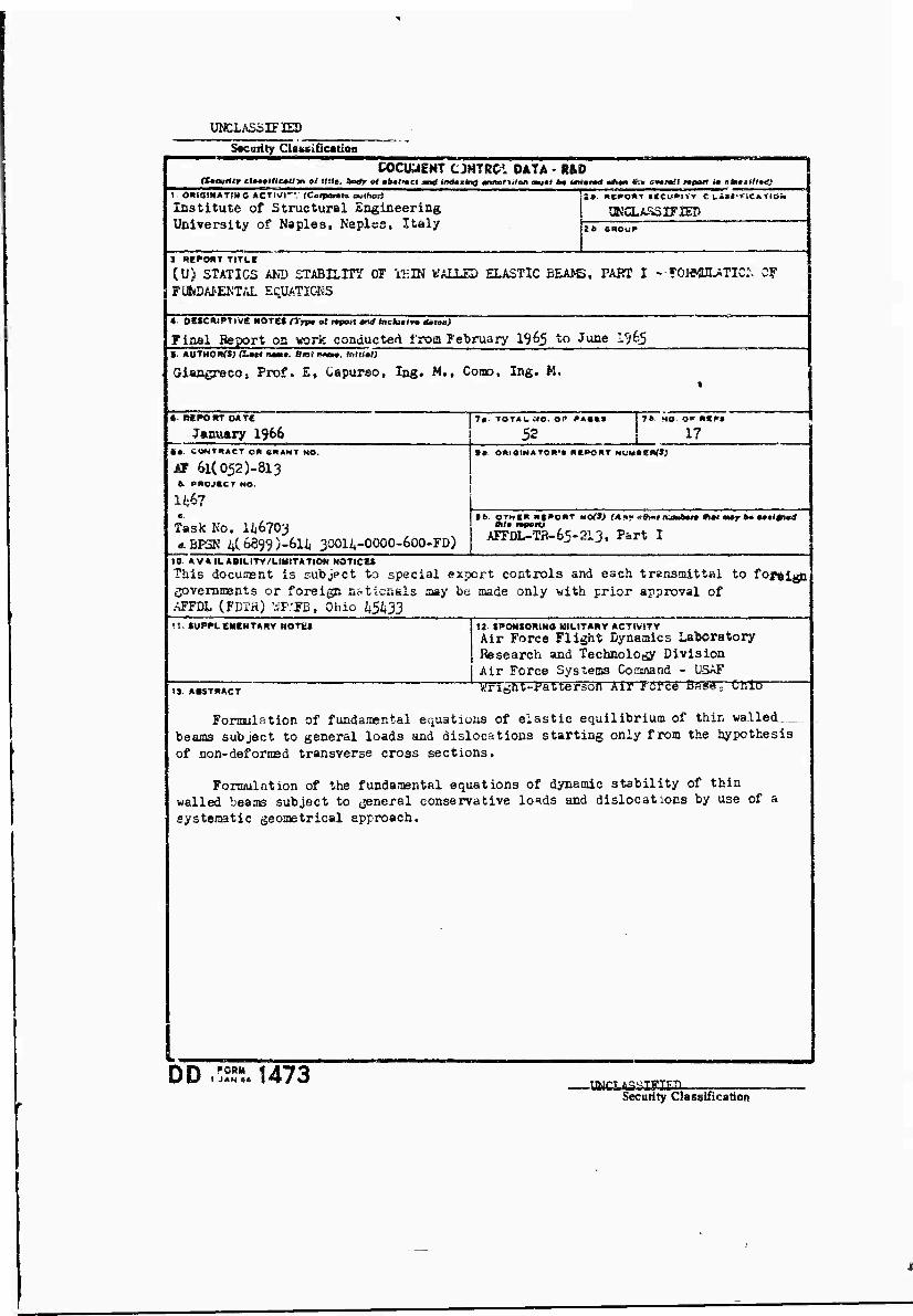
UNCLASSIFIED Security CUssiOcation
COCUUEMT C JHTSCi DATA • R&D (fteutlir clMlHcitlm ol rttit, Scd» of «fc«t»eci antf inMiind annsfiäon auM b* «ntnW •*•» Si» ä»»mJI «POTT im «Intl/IrO
1 —rn I- omaiMATsso *CTI«I—.' rCoipamts aamorj lastltute of Structural Sngineering University of Naples, Naplss, Italy
i» («C^O«T tieu»!** C UlUt'irieaTie*«
SKCUSS1FIES 2 6 «ROuP
» REDOUT TiTtE
CU) STATICS AND STABILIT/ OF i-EDJ WALLED ELASTIC BEA>S, PART I - FOUKUUTIC:-. CF FliiDAI'EKTAL ECUATIC^S
*- OZtCmPTtve HOrtS (Trp» al rtpotttn* tocluHr» dmtex)
Final Beport oa yeork conducted from February 1963 to June 1^65 S «UTHORff) fi«« naB*. Slot www, lullitl)
Giacgreco, Prof. E, Cepurso, Ing. M., COPC, Ing. M.
«. REPORT OJtTC
January 1966 I 7« TOTAU MO. OP PACES
1 52 C*. COWTBACT OR «RANT MO.
ÄF 6i(052)-8i3 b. PROJECT NO.
1467
Task No. 146703 rf.BP3K 4(b899)-6l4 3OOI4-OOOO-6OO-FD)
7*. HO ar R«P»
1? • «. OHiaiNATQK'» RCPGKT NUMSeMfl/
9ft. OTHt« nf^oRT HO($} (Any V0im n'mbmn dm* m*y b* wlfwä Al« mportj
AFFDL-Ta-65-213. P&rt I
tO. AVAILABILITY/LIMITATION NOTICES
This document is subject to special export controls and each transmittal to fontffi governtnents or foreign EJ.ticsals aay be made only with prior approval of AFFDL (FDTH) VJP/FB, Ohio 45433 II. SUPPLEMENTARY NOTES it- SPONSORINO MILITARY ACTIVITY
Air Force Flight Dynemies Laboratory Research and Technology Division Air Force Systems Cosmand - USAF WTght-PaUersbn -Ail? TöTbe BSS^: CRlö (3 ABSTRACT
Fonmuation of fundanental equations of elastic equilibrium of thin wa.lled_„ beams subject to general loads and dislocations starting only from the hypothesis of non-deformsd transverse cross sections.
Formulation of the fundamental equations of dynamic stability of thin walled beams subject to tjeneral conservative lo'ids and dislocations by use of a systematic geometrical approach.
I, DD .Ä 1473 -UWCUSSIKILD-
Security Classification
ülCLA3>"|ITip Seswi^r Ci*««tfiarttoc
«CVWO^M
Statics äüd StabiSity tbsstrtiSMX. Itesul ts
LINK A UMK B «t
UMKC
IV^TRUCTKJÜS l. ORI&lwATiKG »ia-RngS"" Sat« Öu -»»^ sn« »**«» ot the comracS», Müc«K»r<$iM. grants«, S^wtMml o$ Ou- fca«* activüy ar ööI» «iSääMtioa f< oip ;■•*• mthor) iaaoäg sh* '«port. 2* ^KftHiT PRCtWry CLASKTICAIfg)» Erie? «w c-«». oll secürltv Oässtfk-Bjioo of I!»» rujHnt, Imtir te wbnAiK' "lte«tTi9U>4 0£*" U J.icludeA Uariüoc 1» U b« In «coar*- ■bcc »iih a^rapriata security regulatloat, 26. GROUP: Astösaäc dowakraditig is apacUiad lr. DöD Dl- ractivc 9300.10 and Armed ForcM Iisäasttiai Mwsiai. Euter the c-wp ftcc*cr. Also, «hca »«pUcablc, «how tfe«t optional marSelng« Swe been afc«ä for Grotsp 3 and Qroup 4 as Rittksr- iSMt.
3. H^QST TITLE! Enter the conplat« repot, title la all capital tetter*. Tia« lo »11 c«M« «IKRIIIS h* udClaecifletL U a ireaateeful title cannot ha «elected «ithoat claeeißca- tlon, »hin tltt« classification in all capitals in pannthml« J'EMedUtely foüowlng the tUla. 4. ÖESCKIFHVE fWTES: U appropriate, »ntef the type of r«j,ort, «.(,, i(?t«rim, progreaa, «ununary, annucl, or final. Give the inclusive date« when a apeciöc reporting period la covered. 5. AUTHOiKS): Enter the naoa(a) of «uthoK«) a« shown on or in the report. Enter teat name, first name, middie initial. If xilitary; »how rank end branch of service. The name of th» principal üuthor U an absolute minimum requirement. & REPORT DATE: Enter the date of the report as day, month, year, or month, year. If nore than one date eppe^rs on the report, use date of poblicatton. 7*. TOTAL NUMBER OP PACES: The total page count should follow nomal pagination procedure«, Le., enter the number of pages containing information 76. NUMBER OF REFERENCES Enter the total number of reference« cited in the report. i Sa. CONTRACT OR GRANT NUMBER: If «ppropriate, et>ler | the applicable number of the contract or grant wider which i the report wee written. , 8b, 8c, & 84 PROJECT NUMBER: Eater the appropriate military department 'dentiflcation. such ss project number, «ubproject nunfcer, .jstem numbers, task number, etc. 9a. ORIGINATOR'S REPORT NUMBER(S): Enter the offi- cial report number by which the document will be identified and cotttrotled by the originating activity. This number must be unique to this report. 9b. OTHER REPORT NUMBER^)- If the report has been assigned «ny other report number« (either by the originator ot by the tpontai), also enter this numbeK«). 10. AVAILABILITY/UJIITATIOH NOTICSS: Enter sny lim- itstions on further dissemination of the report, other than those
——.linn II.II.I«III „milJ_l!B ore sis-ssi
imposed by security ciatalOcatian, ustng stsadaM statements such as:
"QMllfled reqBwef.sws may obtain c^yi.? of this report from DDC':
"Foreign anoouncement end ossetniaation of this report by DDC is not authorl ted.'' "U. & QovemmenE sujencies may cassia copies of this report directly hvm DOC Ot'ier qoalified DDC users shall reqaest through
(2)
(3)
(4)
(S)
"U. S. military üeencl«» may obt.tlu copies of this repot* directly fcem DDC Os.h« ifialified ussrs shall retpjwi» through
"All distribtttics of tbi« report Is coatraitcd. ified DDC user» shall reauest di'v'igh
Qusi-
If the report ha« been furnished tc th>~ Office of Technical Services, Department of Commerce, tot ;«le to the public, indi- cate this fact sad enter the price, if known. It SUPPLEMENT AR V NOTES: Use for addition«! explad»- tory notes 12. SPONSORING MILITARY ACTIVITY: Enter the na:oe of the departmBn'i! project office or laboratory apoasoring fpey- tng lot) the Msesrch and development Include address. 13- ABSTRACT: Rwier an fS«^mc: giving « brief «nd faciual nummary of tie dn^uneat indicative of the report, even though i\ may »3» appwr c^ewhaie in the body of the technical re- port. If wärini wat «.?Jce i'l required, a continuation sheet shall he attachJsd.
It is t>l(My teiiraMe ti.at the abltrset of classified report« be unclaarnifitrd. Rech peru^mj* of she statract shs.U end with MI indication of tM iniUi«-,' security cUasKication of the ia- jannation io the pawgrn^i pipreseniod ■«; f r.w, (Si <C), or (V).
There «« no Ursusti^n csi die lewfcüi •( tt.v abstract. Hew- «vfr, the »u^ested !«ngv>j is from 151; » !2S word«.
14. KiSY WOKDS; Key wwS« .»re ■e'.vsnict-Uy neaaingful term« or «hart phiase» th»t chansrpsHjte a repctt «nd may be used a« index entries for cataloging the report. SC'iy word« mu«t be «elected so that ao security classification la rsquiied. Identi- fier», such as equipment model designation, trade name, military project code aame, geographic location, may be u««d «s key word« but will be followed by an indication of technical con- text. The «««ignirent of lisk«, rule«, and weight« is optional.
'JNCLASSIFIED
Security Classification
«MU- DU^Mnv^ipMP^ WHTCvavvPMBfpniEaHn: i
SUPPLEMENTARY
INFORMATION
SO
&UAU* «4 St«l>tli1^ of TbiA-ValUA Elastic 8««a* Fart X, ^oxnulAtioa of ruadayeaMtal 8^iMtlo&«
47 Tli^bt BysAKicfl I«tiO»&tcsy B»««ar«ii «ad f«choology Piri«lojj Air?orc# Syst«M« CoasaeiBd Vrigbt-Patte»«» Air ?ore« Bese, Obio
Corer täSSL $& tit^e j^ai* Stride out the stateiaeßt •Piätri&ution of tM.,i SoeaaBfit is aäö.isi*«i,#
a;>». Ada tbe stst^arfn»* «flu. 4o«?j,«»a^ ?.® sus^f-t- ^o ^#t5Ju. export ooatrol» ao4 eacb transaittal to foreign &verDm&ts or föJf*»jS aetioßal» aey b« Asd» only with prior epjroTal of &iVUJvm)t WiStht Ohio 45433*.
TorwiOBi. Tb!» tecfaslcal report has baea ravi«wed a&d is approvad.
Chief * Thaorettcei ^sehasics Braocii structures DiTislon
r
/}/■'