Embed Size (px)
Citation preview
UNCLASSIFIED
AD NUMBER
AD857455
NEW LIMITATION CHANGE
TOApproved for public release, distributionunlimited
FROMDistribution authorized to U.S. Gov't.agencies only; Administrative/OperationalUse; MAY 1969. Other requests shall bereferred to US Army Aviation MaterielLaboratories, Fort Eustis, VA 23604.
AUTHORITY
USAAMRDL ltr, 18 Jun 1971
THIS PAGE IS UNCLASSIFIED
USAAVLABS TECHNICAL REPORT 69-22
1t• SUGGESTED SPECIFICATION FOR A
LIFT FAN PROPULSION SYSTEM
By
Wafter B. Davis D DBsmjamiu W. Ela
May I go
U. S. ARMY AVIATION MATERIEL LABORATORIESFORT EUSTiS, VIRGINIA
CONTRACT DA 44-177.,AMC-345(T)
RYAN AE-KONAUIICAL COMPANY
SAN DIEGO, CALIFORNIA
o ts hd, f e,- lger f. , th"r I
(.t ,zrl t nin It ht 1 j-gýr op.
v*l'l I. ab.,, ,r~t or N'. Fort If' ,r'
irgillia 2 V,0J.
DEPARTMENT OF THE ARMYHEADQUARTERS UZ ARMY AVIATION MATERIEL LABORATORIES
FORT EgSTS. VIRGINIA 23o0A
This report has been reviewed by the US Army AviationMateriel Laboratories and is considered to have a tech-nically sound base.
The lift fan propulsion system component design require-ments offered in this report reflect experience gained
from the XV-SA lift fan aircraft r--ogramu and would be
useful to future designs of lift f- aircraft.
This report is published for the dissemination ofinformation and stimulation of ideas.
*r J 4 I '
Project 1F131201D161Contract DA 44-177-AMC-345 (T)
USAAVLABS Techn•cal Report 69-22May 1969
SUGGESTED SPECIFICATION
FOR A
LIFT FAN PROPULSION SYSTEM
REPORT NO. 29469-3
By
B. W. ElaW. B. Davis
Prepared By
RYAN AERONAUTICAL COMPANY
SAN DIEGO, CALIFORNIA
For
U.S. ARMY AVIATION MATERIEL LABORATORIESFORT EUSTIS, VIRGINIA
Each transmittal of this document outside the agencies of theUS Government must have prior approval of US Army AviationMateriel Laboratories, Fort Eustis, Virginia 23604.
SUMMARY
This report presents propulsion system component design requirementsbelieved to be necessary for successful development of operational lift fanaircraft. The work was done under U. S. Army Aviation Materiel Laboratories(USAAVLABS) Contract DA 44-177-AMC-345(T) from I July 1965 to 1 March 1966for the purpose of identifying lift fan airframe and propulsion systemperformance and installation interfaces. Military specification require-ments are first examined for applicability; they are then expanded ormodified.
The requirements presented in this report reflect experience gained fromthe XV-SA lift fan aircraft flight test program. Requirements in areassuch as flight design loads, reliability and maintainability, and fan con-trol rates are lacking in detail and authority and will need additionaldefinition as new criteria develop.
iii
F
FOREWORD
This report is submitted in partial compliance with Study Contract
DA 44-177-AMC-345(T) with the U.S. Army Aviation Materiel Laboratories.
It contains preliminary propulsion system component design requirements
believed to b: niecessary for the successful development of an operationallift fan airci , -osed on the contractor's experience and the resultsof a Study of Airframe Requirements for Lift Fan Technology Advancement,
USAAVLABSiReport 69-21. Military specification requirements are first exam-ined for applicability; then, they are expanded or modified in the samegeneral order and format used in the presentation of airframe-propulsionsystem interfaces in the above-mentioned report. Some preliminary re-quirements (such as flight design loads, reliability and maintainability,and fan control response rates) are lacking in detail and authority.Work to develop authoritative requirements in these aad other specialrequirement areas should be continued.
V
CONTENTS
SJMARY . . . . . . . .iii
FOREWORD .q.. . . .. . . . . . . . ... o
LIST OF ILLUSTRATIONS . . . . . . . . . . . . . . . .... ii
LIST OF TABLES .*. . . . . . . . . . . . . . . . . . . . . . . viii
L1ST OF SYMBOLS AND ABBREVIATIONS .. .. . . . . . . . . . . . ix
1.0 S& OPE ... . . . . .. . . . .. . . . . . . . .. . 1
2.0 APPLICABLE DOCUMENTS .*. . . . . . . . ..*. .. . . ... 8
3.0 DEFINITIONS . . . . . . . . . . . . . .... ....... . 9
4.0 PERFORI kNCE .*. . . . . . . . . . . . . . . . . . . . . 10
5.0 INSIALLATION FEATURES ..... ......... 22
6.0 ENVIRONMENT . . . . . . . . . . . . . . . . . . . . . 27
7.0 RELIABILITY AND MAINTAINABILITY . . . . . . . . . . . . 31
8.0 QUALIFICATION TESTS . . . . . . . . . . . . . . . . 32
9.0 ACCEPTANCE TESTS . . . . . . . . . . . . . . . . . .. 36
10.0 DATA . . . ................. * . . . . . . . . 37
DISTRIBUTION . . . . . . . . . . . . . . . . . . . . . . . . . 38
vii
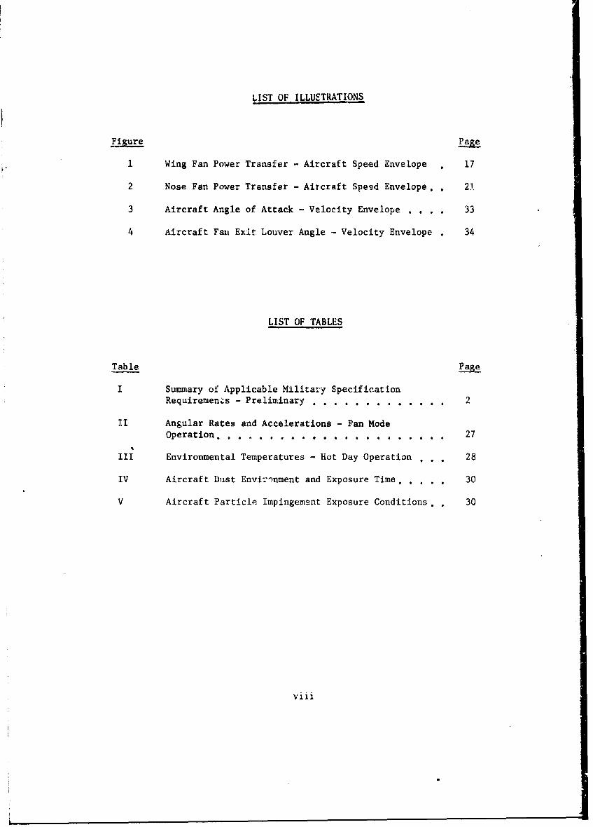
LIST OF ILLUSTRATIONS
1 Wing Fan Power Transfer - Aircraft Speed Envelope . 17
2 Nose Fan Power Transfer - Aircraft Speed Envelope.. 72
3 Aircraft Angle of Attack - Velocity Envelope . . . . 33
4 Aircraft Fani Exit Louver Angle - Velocity Envelope . 34
LIST OF TABLES,
Table Pae
I Summary of Applicable Military SpecificationRequirements - Preliminary . . . . . . . . . . . . 2
II Angular Rates and Accelerations - Fan Mode
Operation ............ . . . . . .. .... * .* .. . 27
III Environmental Temperatures - Hot Day Operation . . . 28
IV Aircraft Dust Environment and Exposure Time. .... 30
V Aircraft Particle Impingement Exposure Conditions.. 30
viii
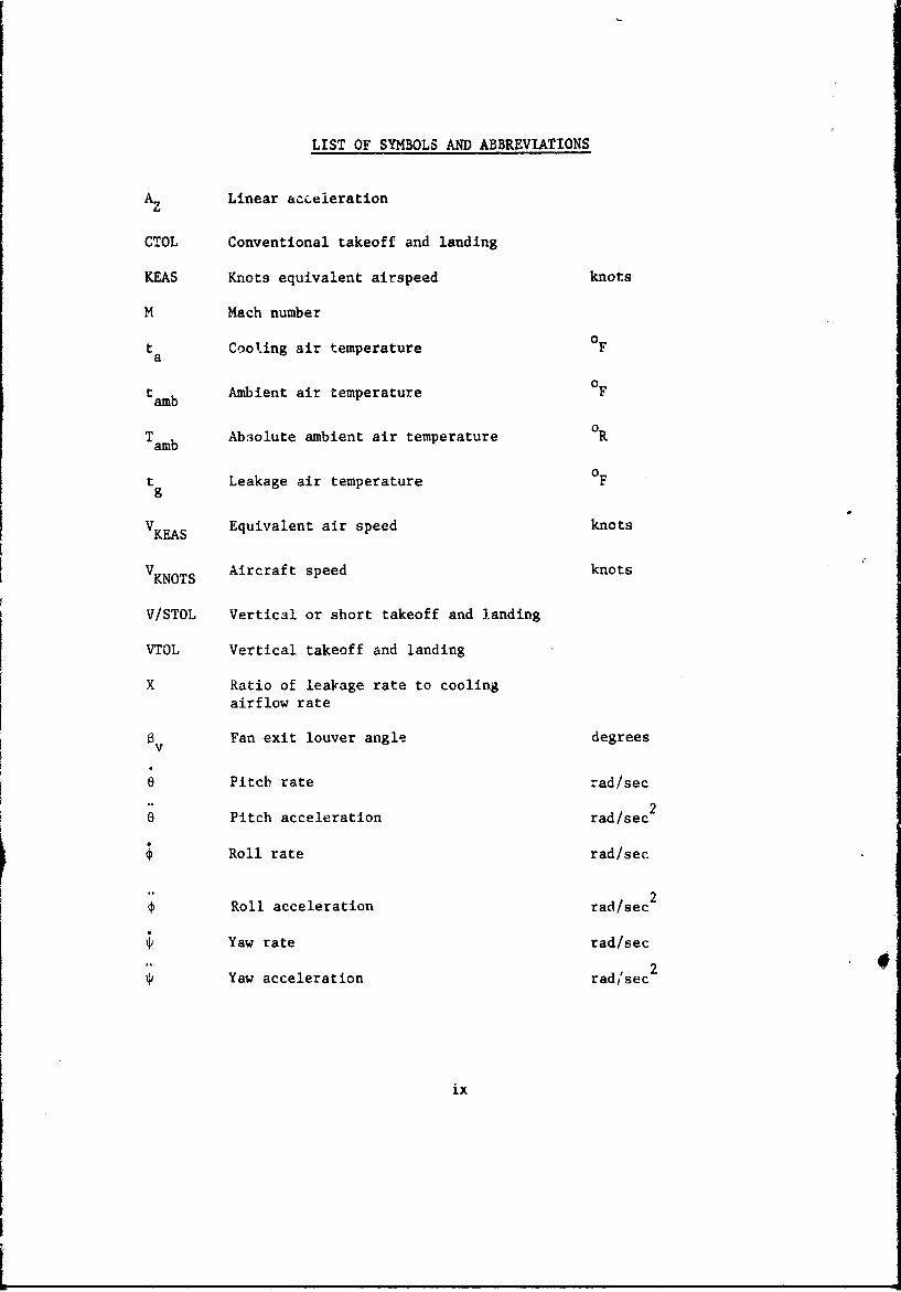
LIST OF SYMBOLS AND ABBREVIATIONS
A Linear ac-eieration
CTOL Conventional takeoff and landing
KEAS Knots equivalent airspeed knots
M Mach number
t Cooling air temperature 0Fa
tamb Ambient air temperature 0F
TAbsolute ambient air temperature OTamb
t Leakage air temperature 0F9
VKEAS Equivalent air speed knots
V KNOTS Aircraft speed knots
V/STOL Vertical or short takeoff and landing
VTOL Vertical takeoff and landing
X Ratio of leakage rate to coolingairflow rate
Fan exit louver angle degreesV
0 Pitch rate rad/sec
o Pitch acceleration rad/sec2
Roll rate rad/sec
Roll acceleration rad/sec 2
Yaw rate rad/sec
Yaw acceleration rad,'sec2
ix
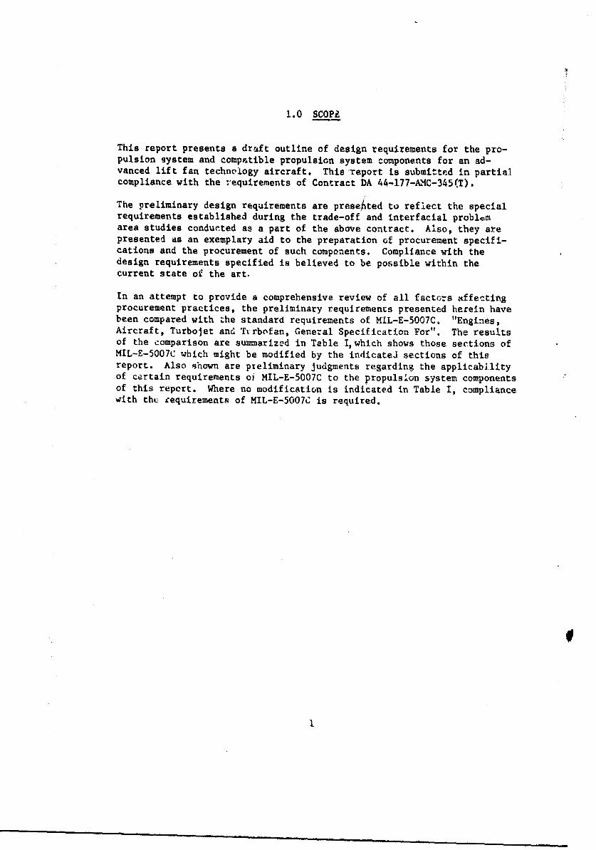
1.0 SCOPE
This report presents a draft outline of design requirements for the pro-pulsion system and compatible propulsion system components for an ad-vanced lift fan technology aircraft. This Teport is submitted in partialcompliance with the requirements of Contract DA 44-177-AI1C-345(T).
The preliminary design requirements are presehted to reflect the specialrequirements established during the trade-off and interfacial problcmarea studies conducted as a part of the above contract. Also, they arepresented as an exemplary aid to the preparation of procurement specifi-cations and the procurement of such components. Compliance with thedesign requirements specified is believed to be possible within thecurrent state of the art.
In an attempt to provide a comprehensive review of all factors affectingprocurement practices, the preliminary requirements presented herein havebeen compared with the standard requirements of MIL-E-5007C. "Engines,Aircraft, Turbojet and Turbofan, General Specification For". The resultsof the comparison are summarized in Table I, which shows those sections ofMIL-E-5007C which might be modified by the indicatel sections of thisreport. Also shown are pzeliminary judgments regarding the applicabilityof certain requirements oi MIL-E-5007C to the propulsion system componentsof this report. Where no modification is indicated in Table I, compliancewith thef equirements of MIL-E-5007C is required.
f
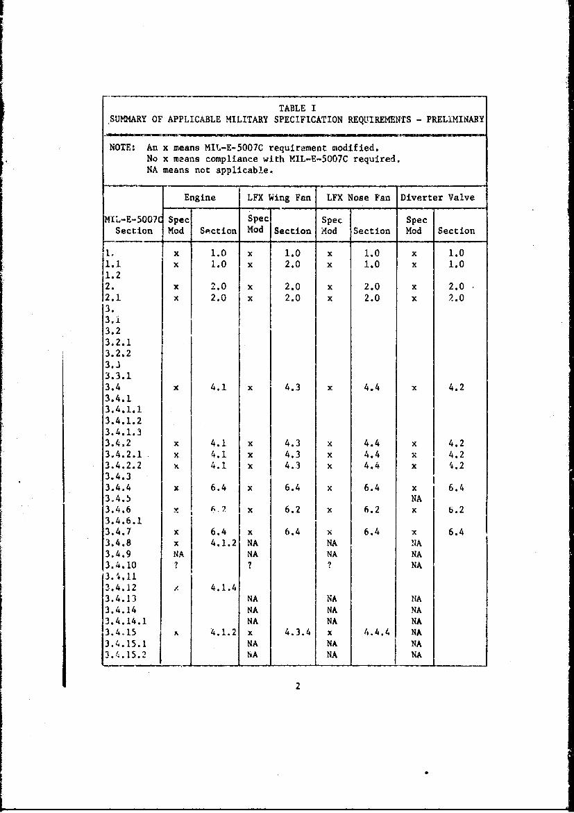
TABLE ISUMMARY OF APPLICABLE MILITARY SPECIFICATION REQUIREMENTS - PRELIMINARY
NOTE: An x means MIL-E-5007C requirement modified.No x means compliance with MIL-E-5007C required.NA means not applicable.
Engine LFX Wing Fan LFX Nose Fan Diverter Valve
MIL-E-5007 Spec Spec Spec SpecSection Mod Section Mod Section Mod Section Mod Section
11 x 1.0 x 1.0 x 1.0 x 1.01.1 x 1.0 x 2.0 x 1.0 x 1.01.23. x 2.0 x 2.0 x 2.0 x 2.02.1 x 2.0 x 2.0 x 2.0 x 2.0
3.3.i
3.2.23,2.13.2.2
3.33.3.13.4 x 4.1 x 4.3 x 4.4 x 4.23.4.13.4.1.13.4.1.23.4.1.33.4.2 x 4.1 x 4.3 x 4.4 x 4.23.4.2.1 x 4.1 x 4.3 x 4.4 x 4.2
3.4.2.2 x 4.1 x 4.3 x 4.4 x 14.23.4.3
3.4.4 x 6.4 x 6.4 x 6.4 x 6 6.43.4.5 NA3.4.6 A.2 x 6.2 x 6.2 x 6.23.4.6.13.4.7 x 6.4 x 6.4 x 6.4 x 6.43.4.8 x 4.1.2 NA NA NA3.4.9 NA NA NA NA3.4.10 ? ? ? NA3.4,113.4,12 L 4.1.43.4.13 NA NA NA3.4.14 NA NA NA3.4.14.1 NA NA NA3.4,15 .1.2 x 4.3.4 x 4.4.4 NA
3.4.15.1 NA NA NANA NA NA
2
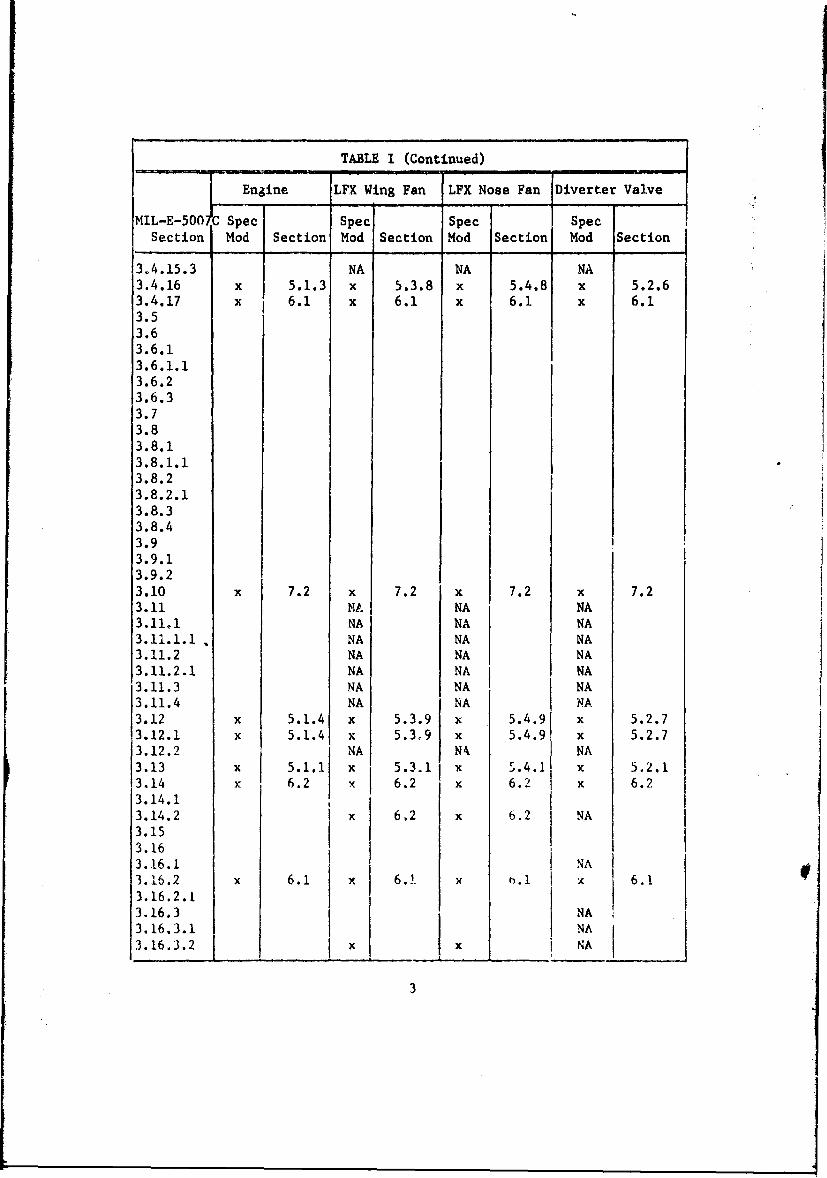
TABLE I (Continued)
Engine LFX Wing Fan LFX Nose Fan Diverter Valve
MIL-E-500 C Spec Spec Spec SpecSection Mod Section Mod Section Mod Section Mod Section
3.4.15.3 NA NA NA3.4.16 x 5.1.3 x 5.3.8 x 5.4.8 x 5.2.63.4.17 x 6.1 x 6.1 x 6.1 x 6.13.53.63.6.13.6.1.13.6.23.6.33.73.83.8.13.8.1.13.8.23.8.2.13.8.33.8.43.93.9.13.9.23.10 x 7.2 x 7.2 x 7.2 x 7.23.11 F.A NA NA3.11.1 NA NA NA3.11.1.1 NA NA NA3.11.2 NA NA NA3.11.2.1 NA NA NA3.11.3 NA NA NA3.11.4 NA NA NA3.12 x 5.1.4 x 5.3.9 x 5.4.9 x 5.2.73.12.1 x 5.1.4 x 5.3,9 x 5.4.9 x 5.2.73.12.2 NA Nk NA3.13 x 5.1.1 x 5.3.1 x 5.4.1 x 5.2.13.14 x 6.2 x 6.2 x 6.2 x 6.23.14.13.14.2 x 6,2 x 6.2 NA3.153.163.16.1 NA3.16.2 x 6.1 x 6.1 t .l x 6.13.16.2.13.16.3 NA3.16.3.1 NA3.16.3.2 x x NA
3
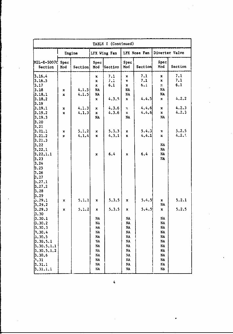
TABLE I (Continued)
Engine LFX Wing Fan LFX Nose Fan Diverter Valve
IL-E-5007 Spec Spec Spec SpecSection j Mod Section Mod Section Mod Section Mod Section
3.16.4 x 7.1 x 7.1 x 7.13.16.5 x 7.1 x 7.1 x 7.1
3.17 x 6.1 x 6.1 N 6.13.18 x 4.1.5 NA NA NA3.18.1 x 4.1.5 NA NA NA3.18.2 x 4.3.5 x 4.4.5 x 4.2.23.193.19.1 x 4.1.3 x 4.3.6 x 4.4.6 x 4.2.33.19.2 x 4.1.3 x 4.3.6 x 4.4.6 x 4.2.33.19.3 NA NA NA3.203.213.21.1 x 5.1.2 x 5.3.3 x 5.4.3 x 5.2.53.21.2 x 4.1.4 x 4.3.1 x 4.4.1 x 4.2.1.3.21.33.22 NA3.22.1 NA3.22.1.1 x 6.4 x 6.4 NA3.23 NA3.243.253.263.273.27.13.27.23.283.29J.29.1 x 5.1.1 x 5.3.5 x 5.4.5 x 5.2.13.29.2 NA3.29.3 x 5.1.2 x 5.3.5 x 5.4.5 x 5.2.53.303.30.1 NA NA NA3.30.2 NA i NA NA3.30.3 NA NA NA3.30.4 NA NA NA3.30.5 NA NA NA3.30.5.1 NA NA NA3.30.5.1.1 NA NA NA3.30.5.1.2 NA NA NA3.30.6 NA NA NA3.31 NA NA NA3.31.1 NA NA NA3.31.1.1 NA NA NA
4
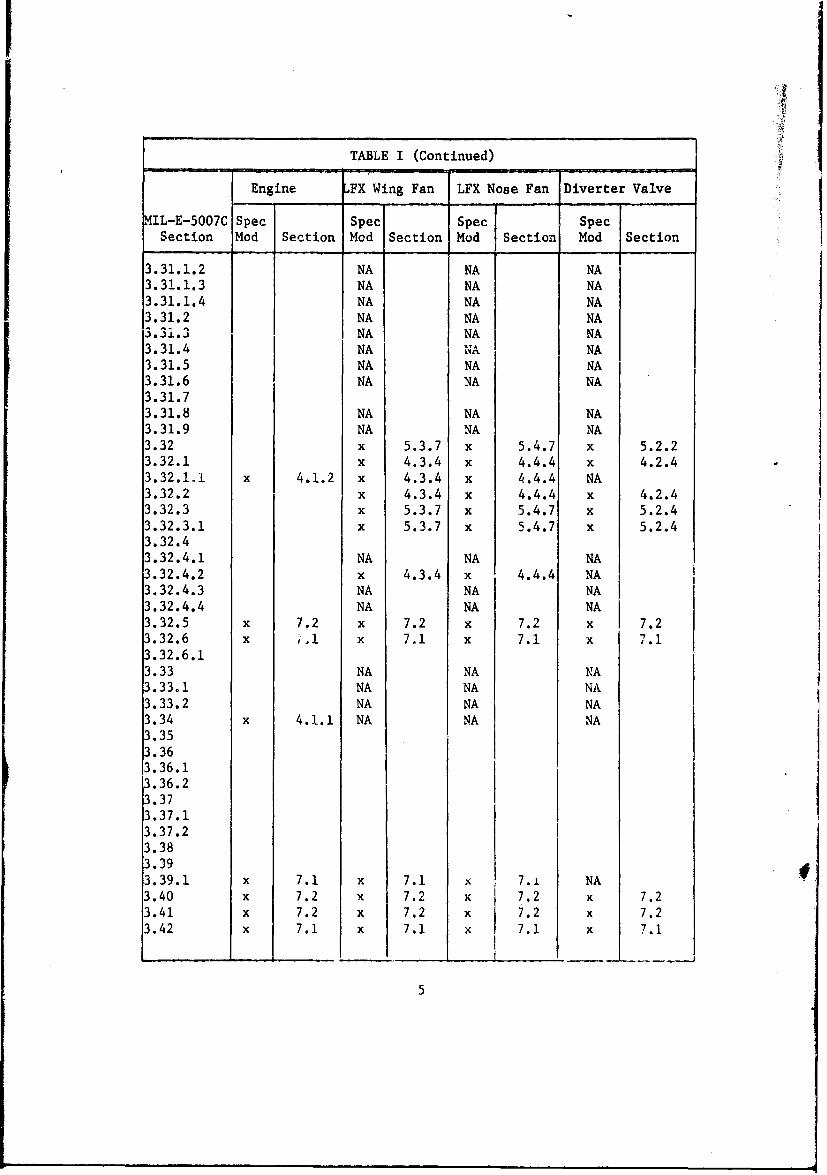
TABLE I (Continued)
Engine LFX Wing Fan LFX Nose Fan Diverter Valve
,IL-E-5007C Spec Spec Spec SpecSection Mod Section Mod Section Mod Section Mod Section
3.31.1.2 NA NA NA3.31.1.3 NA NA NA3.31.1.4 NA NA NA3.31.2 NA NA NA3.31.3 NA NA NA3.31.4 NA INA NA3.31.5 NA NA NA3.31.6 NA NA NA3.31.73.31.8 NA NA NA3.31.9 NA NA NA3.32 x 5.3.7 x 5.4.7 x 5.2.23.32.1 x 4.3.4 x 4.4.4 x 4.2.4
3.32.1.1 x 4.1.2 x 4.3.4 x 4.4.4 NA3.32.2 x 4.3.4 x 4.4.4 x 4.2.43.32.3 x 5.3.7 x 5.4.7 x 5.2.43.32.3.1 x 5.3.7 x 5.4.7 x 5.2.43.32.43.32.4.1 NA NA NA3.32.4.2 x 4.3.4 x 4.4.4 NA ,3.32.4.3 NA NA NA3.32.4.4 NA NA NA3.32.5 x 7.2 x 7.2 x 7.2 x 7.23.32.6 x ,.I x 7.1 x 7.1 x 7.1
3.32.6.13.33 NA NA NA3.33.1 NA NA NA3.33.2 NA NA NA3.34 x 4.1.1 NA NA NA3.353.363.36.13.36.23.373.37.13.37.23.383.393.39.1 x 7.1 x 7.1 7.1 NA3.40 x 7.2 x 7.2 x 7.2 x 7.23.41 x 7.2 x 7.2 x 7.2 x 7.23.42 x 7.1 x 7.1 x 7.1 x 7.1
5
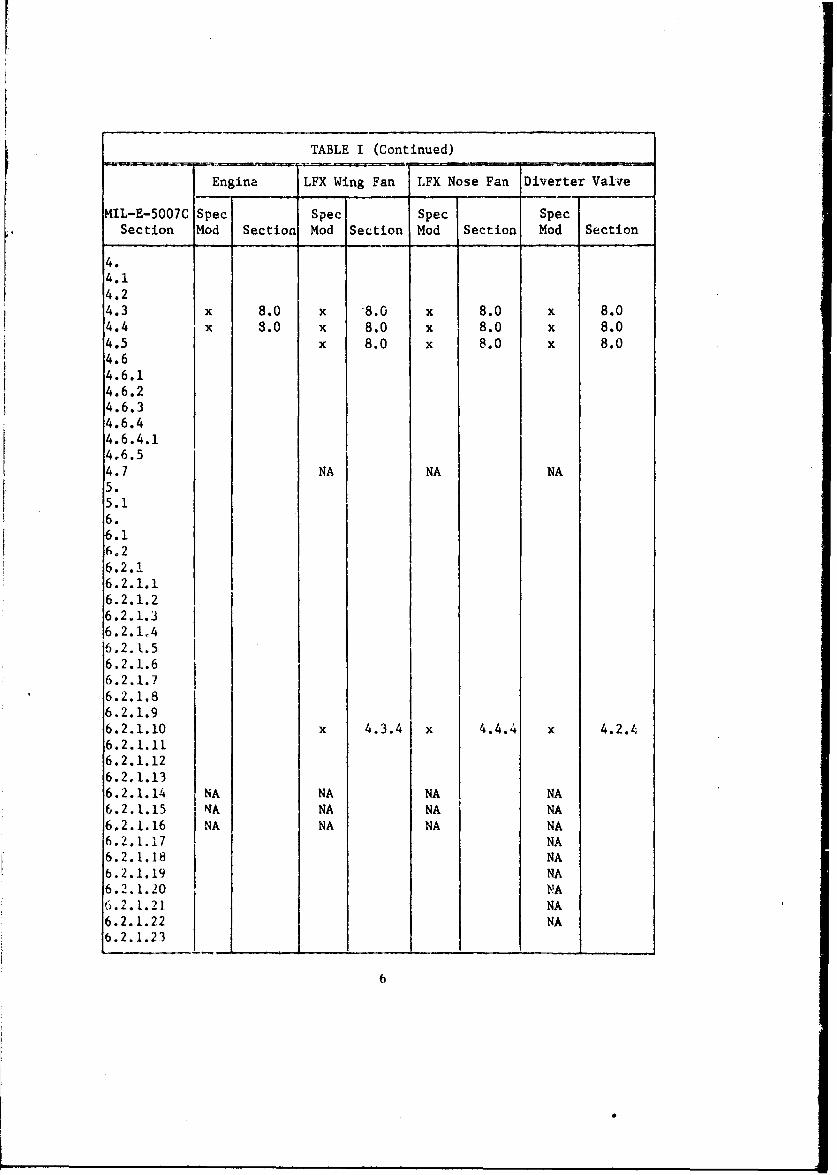
TABLE I (Continued)
Engine LFX Wing Fan LFX Nose Fan Diverter Valve
MIL-E-5007C Spec Spec Spec SpecSection Mod Section Mod Section Mod Section Mod Section
4.4.14.24.3 x 8.0 x 8.0 x 8.0 x 8.04.4 x 3.0 x 8.0 x 8.0 x 8.04.5 x 8.0 x 8.0 x 8.04.64.6.14.6.24.6.34.6.44.6.4.14.6.54.7 NA NA NA5.5.16.6.16.26.2.!6.2.1.16.2.1.26.2.1.36.2.1,46.2.1.56.2.1.66.2.1.76.2.1.86.2.1.96.2.1.10 x 4.3.4 x 4.4.4 x 4.2.46.2.1.116.2.1.126.2.1.136.2.1.14 NA NA NA NA6.2.1.15 NA NA NA NA6,2.1.16 NA NA NA NA6.2.1.17 NA6.2.1.18 NA6.2.1.19 NA6.2.1.20 NA6.2.1.21 NA
6.2.1.22 NA6.2.1.23
6
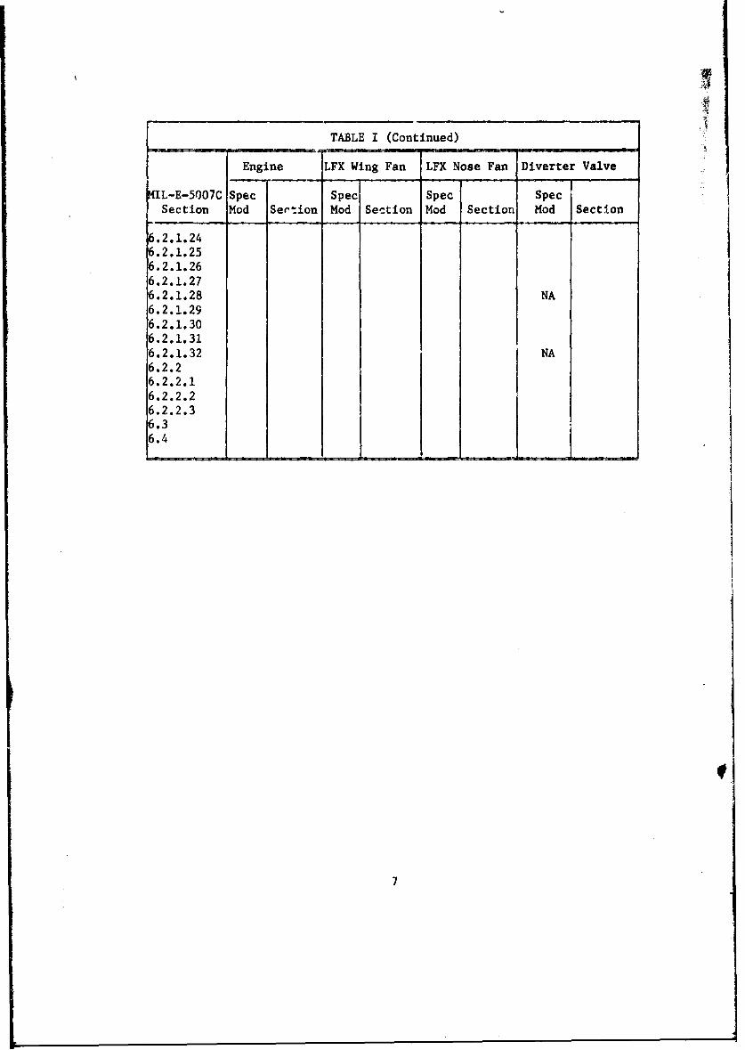
TABLE I (Continued)
Engine LFX Wing Fan LFX Nose Fan Diverter Valve
MIL-E-5007C Spec Spec Spec SpecSection Mod Sertion Mod Section Mod Section Mod Section
6.2.1.246.2.1.256.2.1.266.2.1.276.2.1.28 NA6.2.1.296.2.1.306.2.1.316.2.1.32 NA6.2.26.2.2.16.2.2.26.2.2.36.36.4
7
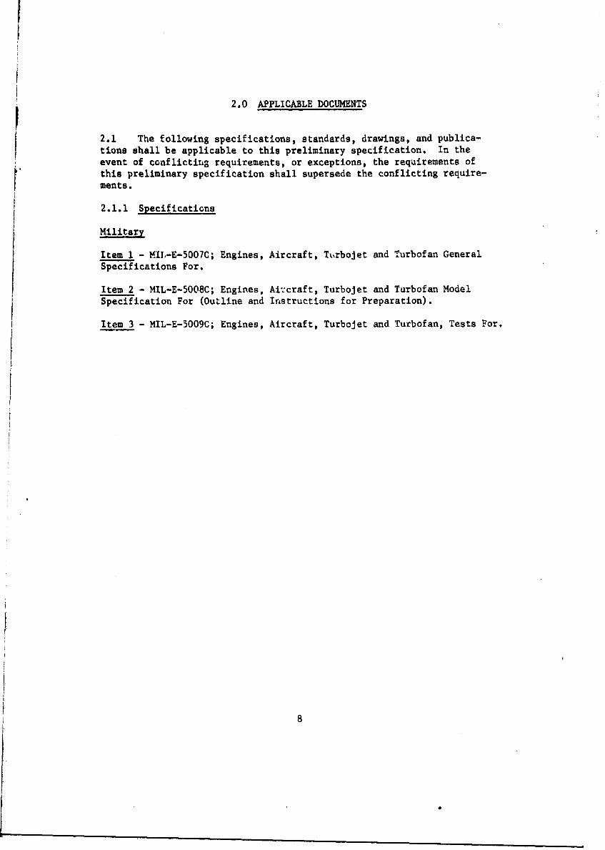
2.0 APPLICABLE DOCUMENTS
2.1 The following specifications, standards, drawings, and publica-tions shall be applicable to this preliminary specification. In theevent of conflicting requirements, or exceptions, the requirements ofthis preliminary specification shall supersede the conflicting require-ments.
2.1.1 Specifications
Military
Item 1 - MIL-E-5007C; Engines, Aircraft, Turbojet and Turbofan GeneralSpecifications For.
Item 2 - MIL-E-5008C; Engines, Aircraft, Turbojet and Turbofan ModelSpecification For (Outline and Instructions for Preparation).
Item 3 - MIL-E-5009C; Engines, Aircraft, Turbojet and Turbofan, Tests For.
8
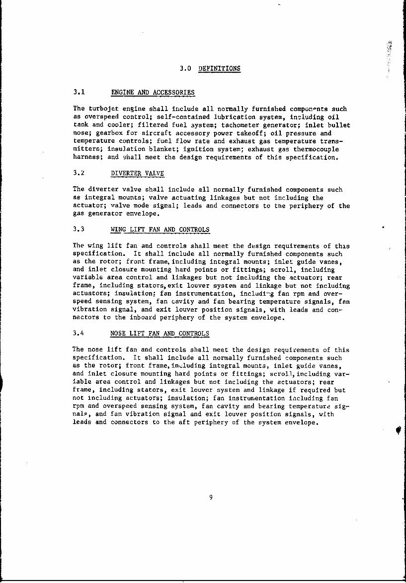
3.0 DEFINITIONS,
3.1 ENGINE AND ACCESSORIES
The turbojet engine shall include all normally furnished compon-nts suchas overspeed control; self-contained lubrication system, insluding oiltank and cooler; filtered fuel system; tachometer generator; inlet bulletnose; gearbox for aircraft accessory power takeoff; oil pressure andtemperature controls; fuel flow rate and exhaust gas temperature trans-mitters; insulation blanket; ignition system; exhaust gas thermocoupleharness; and shall meet the design requirements of this specification.
3.2 DIVERTER VALVE
The diverter valve shall include all normally furnished components suchas integral mounts; valve actuating linkages but not including theactuator; valve mode signal; leads and connectors to the periphery of thegas generator envelope.
3.3 WING LIFT FAN AND CONTROLS
The wing lift fan and controls shall meet the design requirements of thisspecification. It shall include all normally furnished components suchas the rotor; front frame, including integral mounts; inlet guide vanes,and inlet closure mounting hard points or fittings; scroll, includingvariable area control and linkages but not including the actuator; rearframe, including stators, exit louver system and linkage but not includingactuators; insulation; fan instrumentation, includi-tg fan rpm and over-speed sensing system, fan cavity and fan bearing temperature signals, fanvibration signal, and exit louver position signals, with leads and con-nectors to the inboard periphery of the system envelope.
3.4 NOSE LIFT FAN AND CONTROLS
The nose lift fan and controls shall meet the design requirements of thisspecification. It shall include all normally furnished components suchas the rotor; front frame, including integral mounts, inlet guide vanes,and inlet closure mounting hard points or fittings; scroll.,including var-iable area control and linkages but not including the actuators; rearframe, including stators, exit louver system and linkage if required butnot including actuators; insulation; fan instrumentation including fanrpm and overspeed sensing system, fan cavity and bearing temperature sig-nals, and fan vibration signal and exit louver position signals, withleads and connectors to the aft periphery of the system envelope.
9
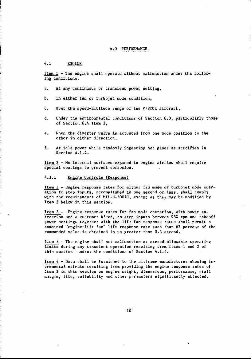
4.0 PERFORMANCE
4.1 ENGINE
Item . - The engine shall operate without malfunction under the follow-ing conditions:
a. At any continuous or transient power setting,
b. In either fan or turbojet mode condition,
c. Over the speed-altitude range of tne V/STOL aircraft,
d. Under the environmental conditions of Section 6.0, particularly thoseof Section 6.4 Item 3,
e. When the diverter valve is actuated from one mode position to theother in either direction,
f. At idle power while randomly ingesting hot gases as specified inSection 4.1.4.
Item 2 - No internai surfaces exposed to engine airflow shall requirespecial coatings to prevent corrosion.
4.1.1 Engine Controls (Response)
Item 1 - Engine response rates for either fan mode or turbojet mode oper-ation to step inputs, accomplished in one secor4 or less, shall complywith the requirements of MIL-E-5007C, except as they may be modified byItem 2 below in this section.
Item 2 - Engine response rates for fan mode operation, with power ex-traction and a customer bleed, to step inputs between 95% rpm and takeoffpower settings together with the lift fan response rates ahall permit acombined "engine-lift fan" lift response rate such that 63 perceiic of thecommanded value Is obtained in no greater than 0.3 second.
Item 3 - The engine shall not malfunction or exceed allowable operatinglimits during any transient operation resulting from Items I and 2 ofthis section and/or the conditions of Section 4.1.4.
Item 4 - Data shall be furnished to the airframe manufacturer showing in-cremental effects resulting from providing the engine response rates ofItem 2 in this section on ergine w¢eight, dimensions, performance, stallmargin, life, reliability and other parameters significantly affected.
10
4.1.2 Heat Rejection
Item 1 - No engine case materials or engine mounted components shall ex-ceed their allowable temperature limits when surrounded by still airunder the following conditions:
a. The conditions specified in Section 3.19 of MIL-E-5007C.
b. Continuous operation with ambient air maintained at MIL-STD-210Ahot day sea level conditions plus 90°F (50 0 C) when surrounded bya reflective enclosure, the engine facing walls of which are main-tained at the above ambient air temperature and have a reflectivitygreater than 80%.
Item 2 - A nonwicking, pressure-vented, foil covered insulation blanketmay be used on the burner section of the engine.
Item 3 - Total heat rejection data shall be provided for all engineoperating conditions .ithin the speed-altitude envelope of the V/STOLaircraft.
4.1.3 Stall Margin Parameter Limits
Item 1 - In addition to the conditions of MIL-E-AO07C, Section 3.4.12,compressor stall shall not occur under any conditions due to tempeiatureand pressure fluctuations resulting from hot gas ingestion under thefollowing conditions:
a. The range of increase in average inlet air temperaturu due to hotgas ingestion shall be from 0°F to 115°F with local hot streakscorresponding to 10 percent of the total inflow to 250°F aboveambient temperature.
b. The range of temperature fluctuation shall occur within a range oftime intervals varying from 0.1 to 5.0 seconds.
c. The duration of randomly fluctuating hot gas ingestion conditionsshall not be less than 2.G minutes.
Item 2 - No compressor stall shall be experienced when the engine is op-eratinc' under the combined conditions of Item I of this section and therequirements of Section 4.1.2, Item 1.
Item 3 Special engine requirements that require a moc -ication of theinlet internal airflow shall not be permitted.
Item 4 - Compressor stall shall not occur under any operaLing conditionwith che engine inlet airflow distortions defP-od below:
a. No ccmpressor stall shall be experienced under any combination ofpressure distribution corresponding to a total pressure distortionindex of 15% and a static pressure distortion index of 8%.
11
b. The total pressure distortion index is defined as the differencebetween the maximum and minimum total pressures divided by theaverage total pressure over the cnmpressor face.
c. The static pressure distortion index is defined as the di.ffc.encebetween the maximum and minimun static pressures divided by theaverage total pressure across the compressor face.
d. The requirements of this item shall apply over the entire compressorface except for the annular areas in contact with the inner hub andthe outer wall surfaces and which extend radially from the surfaces,a distance of 3 percent of the inlet radius.
Item 5 - Complete substantiating analytical and test data shall be re-quired to show compliance with the requirements of this section.
4.1.4 Installed Performance Computer Routine
Item 1 - An estimated installed performance deck shall be provided to-gether with complete operating instructions for its use in accordance withthe following items.
Item 2 - The deck shall permit investigation of the effect of the follow-ing variables on installed performance: altitude, ambient temperature,power setting, inlet pressure recovery, compressor bleed air and powerextraction, changes in interstage bleed air schedule, exhaust gas ductingpressure loss from station to station, and thrust nozzle area and flowcoefficient.
Irem 3 - The deck output shall include conventional output parameters!,lus ideal gas horsepower, gas flow rate, and total pressure at variousstations along the exhaust gas ducting system.
4.k DIVERTEi VALVE
Item I - The diverter valve shall operate without malfunction under thefollowing conditions:
a. At any continuous or transient engine power setting,
b. In eithe. ý. or ý,&L.ojet mode position, and during changes iromeither position to the other,
c. Over the speed-altitude range of the V/STOL aircraft,
d. Under the environmental conditions of Section 6.0. particularly thoseof Section 6.4, Item 3.
12
4.2.1 ?ressure Losses
Item 1 - The pressure los8 of the diverter valve in the turbojet modeposition shall not exceed 2.5 percent of the inlet total pressure; howevera pressure loss of 1.0 percent shall be a design objective.
Item 2 - The pressure loss of the diverter valve in the fan mode positionshall not exceed 3.5 percent of the inlet total pressure; however, apressure loss less than 2.5 percent of the iniet total pressure shall bea design objective.
Item 3 - Substantiating analytical and tesý data shall be furnished show-ing compliance with the requirements and objectives of Items 1 and 2 ofthis section.
4.2.2 Leakage
Item I - Diverter valve leakage in the turbojet mode position shall notexceed 1.0 percent by weight of the inlet gas flow. A leakage rate ofless than 0.25 percent shall be a design objective.
Item 2 - Diverter valve leakage in the fan mode position shall not exceed0.5 percent by weight of the inlet gas flow. A leakage rate of less than0.25 percent shall be a design objective.
Item 3 - There shall re no measurable leakage from the diverter valvethrough the actuation mechanisms.
Item 4 - There shall be nc measurable leakage from the end flanges of thediverter valve.
Item 5 - Substantiating analytical and test data shall be furnished show--ing compliance with the requirements and objectives of items of thissection.
.2.3 Heat Rejection
Item I - No diverter valve materials or divcrter valve mounted componen.sshall exceed their allowable temperature limits when surrounded by stillair under the following conditions:
a. The conditicns specified in MIL-E-5007C, Section 3.19.
b. Contiuu~us operation with ambient air mainiained at MIL-STD-210A hotday sea level conditions plus 135°F (75 0 C) when surrounied by arefl..cive enclosure, the engine facing walls of which are main-tginCa at the above ambient temperature and have a refiectivitygreater than 80%.
Item 2 - A nonwicking, pressure vented, foil covered insulation blanketshall be installed on the external diverter valve surface. The insulationblanket shall not interfere in any way with the dctutation of the diverter
13
valve.
Item 3 - Total heat rejection data shall be provided for all engine oper-ating conditions within the speed-altiLude envelope of the V/STOL air-craft.
4.2.4 Door Actuation
Item 1 - The diverter valve doors shall be capable of being actuated fromone mode position to the other in either direction within 0.2 second, andcomplete travel shall be accomplished within the specified time interval,at all conditions specIfied in Section 4.2, Item la.
Item 2 - The diverter valve door shall not depart from its design modepositior after actuation under any operating conditions.
Item 3 - Substantiating analytical and test data shall be supplied show-ing 'ompllance with the requirements of this section.
4.3 WING LIFT FAN
Item 1 - The wing lift fan performance shall not be less than that pre-sented in the Wing Fan Model Specification or the special requirementsof the following subsections, whichever are greater.
Item z - The wing lift fan shall operate without malfunction under thefollowing conditions:
a. At any continuous or transient engine power setting,
b. Over the fan mode speed-altitude envelope of the V/STOL aircraftand during conver iions from VTOL to CTOL and CTOL to VTOL configura-tions,
c. Under the environmental conditions of Section 6.0, particularly thoseof Section 6,4, Item 3,
d. During transients immediately following diverter valve positionactuotlon at any power setting,
e. Over the full range of scroll area adjustment to the properlyspecified values,
f. One engine nonoperating with no affect on the performance oF theremainfii, engine.
4.3.t Hover Lift
Item I - Tht wing fan lift for APOC standard day sea level conditionsshall not be less thAn _ pounds at heights above the ground planeequivalent to one fan diameter a3d abovewhen tha wing fan, the wingfan bellmouth, and the exit closure and louver ýystem are designed for
14
the following conditions:
a. Wing Fan
(1) Pressure ratio =
(2) Fan tip diameter = __ inches
(3) Power transfer = %
b. Wing Fan Bellmouth
(1) Bellmouth radius = %
(2) No inlet guide vanes
(3) Inlet pressure loss = %
c. Wing Fan Exit Louvers and Closure System
(1) Loss of lift % when
(2) Vectored fan stream angle = 0
d. Engine Operating Conditions
(1) Inlet pressure recovery %
(2) Takeoff power setting
(3) Bleed air extraction = %
(4) Power extraction = horsepower
(5) Exhaust gas flow minus % leakage = pounds per second
e. Scroll Inlet Conditions
(1) Inlet gas flow in percent of total gas flow from oneengine in Item ld(5) of this section = %
(2) Inlet total pressure equal to the engine exhaust gas pressureminus pressure losses of % for the diverter valve and %for the interconnecting ducting. Scroll pressure lossesequal %
Item 2 - The wing fan inlet bellmouth radius shall not exceed ___%of the fan tip diameter. Equivalent bellmouth contours may be selectedfrom NACA Series 1 inlet cocordinates and shall not exceed a height abovethe rotor corresponding to the above requirement.
Item 3 - Inlet guide vanes snall be permissible if necessary to meet therequirements of Item 1 of this section; however, they shall not extendabove 1.5 inches below the bellmouth in]et envelope as established inItem 2 of this section, they shall be capable of operatLon under all fanflight conditions, and they shall not produce adverse effects duringlateral and aft translation velocities to 50 knots.
15
Item 4 - Provisions stalV be made for the wing fan to pump from the scrollcompartment, cooling air at ambient atmospheric pressures at a rate equiv-alent to 0.5% of the fan inlet airflow rate when operating at 100% fanspeed. The incremental weight and dimensional changes for providing thiscapability shall be presented to the airframe manufacturer and the pro-curing service in the wing fan model specification.
Item 5a. The power transfer scroll area control system shall provide a linear
variation of lift with respect to area control input displacementand the design shall consider the following factors:
(1) Increasing or decreasing the inactive turbine admission arc byclosing or opening individually and sequentially only thosescroll nozzle ports necessary to achieve the required areachange.
(2) Increasing or decreasing the inactive turbine admission arc bypartially closing or opening arc segments, with the arc seg-ments operating sequentially following complete closing or open-ing as necessary to achieve the required area change.
(3) A nozzle area control device that shall iiot interfere with the
gas flow when the nozzle is completely open.
(4) A nozzle area control device that is located in the gasflow stream.
b. Analytical and test data shall be presented,showing incremental per-formance, weight, dimensions, and actuating loads for the factors ofthis section, to the airframe manufacturer and procuring service inthe model specification.
Item 6
a. No wing fan materials or components or wing fan mounted componentsshall exceed their allowable temperature limits when the wing fan ismounted in a simulated fan mode aircraft wing structure surroundedby still air at an ambient air temperature of 32C°F (160'C) andoperated under any combination of power transfer conditions specifiedin Item la(3) of this section, engine power settings, and the condi--tions of Section 4.1.2, Items 1 and 2.
b. No wing fan materials or comp...nts or wing fan mounted componentsshell exceed their allowable temperature limits when completely en-closed in a simulated turbojet mode aircraft wing structure andclosure structure which is surrounded by still air when
(1) subjected to the diverter valve leakage specified in Section4.2.2, Item 1,
16
(2) the outside ambient air temperature is equal to MIL-STD-210A
hot day sea level conditions, and either
(3) no cooling air is provided, or
(4) a specified amount of cooling air is provided by a coulingsystem which is integral with the wing fan.
c. Analytical and test data shall be provided to the airframe manu-facturer and to the procuring service with the model specification,showing incremental performance, wcight, and dimensional and oper-ating penalties for the conditions of this section.
Item 7 - The wing fan exit louver system shall be capable of efficientlyvectoring the fa, efflux statically over a range from 25 degrees forward(v = -25°) to -5 degrees aft (5v = 450).
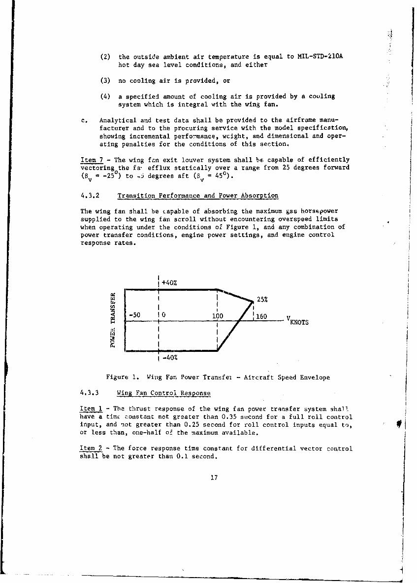
4.3.2 Transition Performance and Power Absorption
The wing fan shall be capable of absorbing the maximum gas horsepowersupplied to the wing fan scroll without encountering overspeed limitswhen operating under the conditions of Figure 1, and any combination ofpower transfer conditions, engine power settings, and engine controlresponse rates.
I +40%
W! 25%j
i00 160 KNOTS
S-40%
Figure 1. Wing Fan Power Transfei - Aircraft Speed Envelope
4.3.3 Wing Fan Control Response
Item 1 - The thrust response of the wing fan power transfer system shallhave a timc constant not greater than 0.35 second for a full roll controlinput, and not greater than 0.25 second for roll control inputs equal to,or less than, one-half o; the maximum available.
Item 2 - The force response time constant for differential vector controlshall be not greater than 0.1 second.
17
I
Item 3 - The time constants of Items I and 2 of this section shall apply
throughout the range of 95 percent to 100 percent engine rpm.
4.3.4 Leakag.e
Item I - The internal wing fan leakage capable of entering the wing fanscroil cavity shall not exceed 0.2 percent of the design gas flow rateof Section 4.3.1, Item ld(5), under any fan mode operating condition.
Item 2 - No external hot gas leakage into the wing fan szroll cavity shallbe permitted under any fan mode operating condition as a result of spil-lage or deflection from the wing fan louver or closure system.
4.3.5 Heat Rejection
Item I - The heat rejection from the wing fan system, including hot gasleakage which shall be specified separately, when operating in the fanmode shall be in accordance with the wing fan model specification,whenthe wing fan is installed in a simulated wing structure and surroundedby ambient air at ARDC standard day sea level temperature flowing at avelocity of 30 feet/second.
Item 2 - Use of pressure vented foil covered insulation blanket isrecommended.
Item 3 - Analytical and test data shall be presented to the airframemanufacturer and to the procuring service in the model specification, show-ing incremental changes in weight, dimensions, and lift performance, andheat rejected by the wing fan system and cooling air outlet temperatureas a function of cooling airflow rate.
4.3.6 Installed Performance Computer Routive
Item 1 - An estimated installed wing fan performance deck for staticconditions shall be provided, together with complete operating instruc-tions for its use.
Item 2 - The deck of Item 1 of this section shall permit investigation ofthe effect on lift fan performance during hovering of the following var-iables:
a. Scroll inlet conditions, including gas flow rate, total temperatureand total pressure,
b. Fan turbine admission scroll arc with either one or two inactivearcs covering the power transfer range required by Section 4.3.1,Item la(3), and for the recommended scroll area control systemresulting from Section 4.3.1, Item 5,
c. Fan inlet pressure losses,
18
d. Fan exit louver angle over the range of ±25 degrees (v ±250),
e. Fan height above the ground level for a range of height to fandiameter ratios from 0.5 to 4.0,
f. Ambient conditions of temperature and pressure for ARDC standard dayand MIL-STD-210A hot and cold das with provisions for temperatureincrements to 300F due to hot gas ingestion,
g. Altitudes from sea level to 10,000 feet.
Item 3 - The deck of Item 1 of this section shall provide the followingoutput data:
a. Input data of Item 2 of this section,
b. Identifying case number,
c. Gas horsepower supplied to the scroll inlet,
d. Wing fan lift and disk loading,
e. Velocities and dynamic pressures of the fan and turbine exhaust gasstreams,
f. Weight flow rate of the fan stream,
g. Effective area of the scroll area,
h. Secondary cooling airflow rate provided for in Section 4.3.1, Item 4.
Item 4 - Provisions shall be included in the deck of Item 1 of this sec-tion to estimate the effects of cross-flow on fan performance parametersbased on experimentally developed correlations.
4.4 NOSE LIFT FAN
Item I - The nose lift fan performance shall not be less than that pre-sented in the nose fan model specification or the special requirements ofthe following subsections, whichever are greater.
Item 2 - The nose lift fan shall operate without malfunction for the con-ditions of Section 4.3, Item 2.
4.4.1 Hover Lift
Item - The nose fan lift for ARDC stanaard day sea level conditionsshall not be less than pounds at 0 percent power transfer and atheights above a ground pl-ne equivalent to one diameter and above when thenose fan, nose fan bellmouth, an,' the exit closure and louver systems aredesigned for the following conditions:
19
• . [T| ITI m11 . . . . I
a. Nose fan
(1) Pressure Ratio -
(2) Fan Tip Diameter = inches
(3) Power Transfer = +___ percent to _ percent
b. Nose Fan Bellmouth
Same as Section 4.3.1, Item ib,
c. Nose Fan Exit Louvers and Closure System
Same as Section 4.3.1, Item ic,
d. Engine Operating Condition
Same as Section 4.3.1, Item Id,
e. Scroll Inlet Conditions
(1) Inlet gas flow in percent of total gas flow from one enginein Section 4.3.1, Item ld(5) =percent
(2) Inlet total pressure same as Section 4.3.1, Item le(2)
Item 2 - The nose fan inlet bellmouth requirements shall be the same asSection 4.3.1, Item 2.
Item 3 - Nose fan inlet guide vanes requirements and condition shail bethe same as'Section 4.3.1, Item 3.
Item 4- Nose fan cooling air pumping requirements shall be the same asSection 4.3.1, Item 4.
Item 5 - Nose fan power transfer scroll area requirements shall be thesame as Section 4.3.1, Item 5, plus the following:
a. Continuous modulation of the nose fan scroll area to zero flow area(0% of the gas flow of S-ction 4.3.1, Item ld(5), and
b. Hot gas leakage through the scroll irea control system shall not ex-ceed 0.5% of the design flow rate to the nose fan specified in Itemle(l) of this section when the nose fan is in the zero flow areaposition.
Item 6 - Operating temperature requirements of Section 4.3.1, Item 6, shaUapply to the nose fan plus the leakage condition of Item 5b of this sec-tion.
20
4.4.2 Transition Performance and Power Absorption
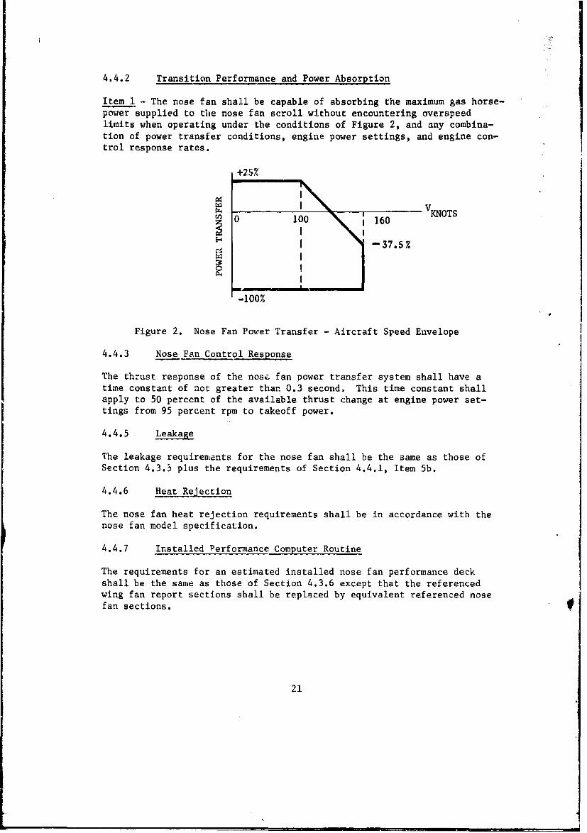
Item 1 - The nose fan shall be capable of absorbing the maximum gas horse-power supplied to the nose fan scroll without encountering overspeedlimits when operating under the conditions of Figure 2, and any combina-tion of power transfer conditions, engine power settings, and engine con-trol response rates.
SV • OTS
H -37.5 %
-100%
Figure 2. Nose Fan Power Transfer - Aircraft Speed Envelope
4.4.3 Nose Fan Control Response
The thrust response of the nose fan power transfer system shall have atime constant of not greater than 0.3 second. This time constant shallapply to 50 percent of the available thrust change at engine power set-tings from 95 percent rpm to takeoff power.
4.4.5 Leakage
The leakage requirements for the nose fan shall be the same as those ofSection 4.3.5 plus the requirements of Section 4.4.1, Item 5b.
4.4.6 Heat Rejection
The nose fan heat rejection requirements shall be in accordance with thenose fan model specification.
4.4.7 Installed Performance Computer Routine
The requirements for an estimated installed nose fan performance deckshall be the same as those of Section 4.3.6 except that the referencedwing fan report sections shall be replaced by equivalent referenced nosefan sections.
21
5.0 INSTALLATION FEATURES
5.1 ENGINE
5.1.1 MounLing
Item 1 - The engine shall have a mount point on either side, either mountto be used individually for vertical loads only. Fitting shall accept auniball rod end in double shear.
Item 2 - Rear engine flange will attach to diverter valve on which shallbe incorporated the additional mounting points required by Section 5.2.1.
5.1.2 Mating With Diverter Valve and Accessories
5.1.2.1 Engine and Diverter Valve Interconnect - The rear engine flangeshall be bolted to the diverter valve front flange. The machined flangeshall be of tapered cross section, spotfaced, indexed, and interchangeable
5.1.2.2 Engine Air Inlet - The engine air inlet flange on the engineshall provide for such alignment as is required by the engine.
5.1.2.3 Fuel - Only one fuel connection shall be required. It shall beeasily removable with standard tools. The engine fuel inlet shall be ca-pable of accepting fuel containing contamination up to 200 microns perMIL-E-5007C.
5.1.2.4 Temperature and Pressure Sensing - Except by special permission,temperature and/or pressure sensors shall be engine mounted so that thereshall be no requirement for airframe-engine interconnects to provide tem-perature or pressure signals to the engine. Fermission for deviation fromthis requirement may be granted by the airframe manufacturer.
5.1.2.5 Accessory Provisions
Item I - A standard AND pad capable of accepting a flexible shaft forpower takeoff and/or starter, shall be provided. Clearance for shaft andproper access shall be provided. It shall be capable of transmitting notless than HP at not w~ore then rpm.
5.2 DIVERTER VALVE
5.2.1 Mounting
Item I - The diverrer valve shall provide a spherical mount fitting whichshall be capable of a'cepting such loads as may be imposed by the engineand diverter valve assembly. This mount point will accept loads in alldirections.
22
Item 2 - A second clevis fitting capable of accepting a uniball bearingbolted in double shear shall accept horizontal loads perpendicular tothe line between the other two engine and diverter valve mounts.
5.2.2 Door Adjustment
Pos 4tive adjustment of the fan duct closure doors within ±2 Inchesof the fan mode design position in 0.5-i.nch increments and a position in-dexing device shall be provided.
5.2.3 Actuation
The time required for the diverter valve to move from one mode positionto the other in either direction shall not exceed 0.2 second.
5.2.5 Mating to Engine and Ducting
Item 1 - For diverter valve to engine mating requirements, refer toSection 5.1.2.1.
Item 2 - The diverter valve connections to the ducting and the tailpipeshall be accomplished by means of V-band couplings and sheet metal flex-ible flanges.
Item 3 - Hot gas leakage at the mating flanges shall not exceed 0.0003%of the inlet gas flow rate.
5.2.6 Instrumentation
Item 1 - A diverter valve mode position sensor shall be provided.
5.2.7 Weight
The weight of the diverter valve shall be provided in the model specifi-cation.
5.3 WING LIFT FAN
5.3.1 Mounting
Item 1 - The wing fan mounting shall be in accordance with the wing fanmodel specification.
Item 2 - The wing fan mounting design shall consider the followingfactors:
a. The wheel and bearings mounted on an aircraft-supplied spindleshaft.
b. The scroll suspended by three mounting links frow which the support-ing beams will permit it to move to a position of proper alignmentafter expansion.
23
c. The fan rear frame halves suspended from the scrolls at the frameperiphery and hinged from the chordwise louver support beam.
Item_ 4 - Analytical and test data shall be presented in the model speci-fication showing incremental performance, weights, maintenance, relia-bility, response, and dimensional data for the factors of this sectioncompared to the selected mounting system.
5.3.2 Envelope
Item 1 - The wing fan envelope shall be in accordance with the wing fanmodel specification.
Item 2 - The wing fan envelope design shall consider the folluwingfactors:
a. A tradeoff study to determine the effects of critical components anddesign decisions on the wing fan envelope dimensions with particularemphasis being focused on factors affecting fan thickness and radialdimensions and their effect on fan performance.
b. The tradeoff shudy shail include consideration of the following:offset bearings, the design division of gas powar between the fanturbine and the turbine exhaust, scroll inlet gas conditions,scroll pressure losses, partial admission end losses, fan turbineblade characteristics, and the requirements of Section 5.3.6.
Item 2 - Analytical and test data shall be presented in the model speci-fication showing incremental effects resulting from the factors consideredin the tradeoff study of this section compared to the specificationenvelope.
5.3.3 Scroll Mating with Ducting
Item I - The wing fan scroll connection to ducting shall be accomplishedby means of V-band couplings and sheet metal flexible flanges.
5.3.4 Inlet and Structure
The inlet bellmouth and structure shall be supplied by the airframe manu-facturer. It shall contain provisions required for fan component attach-ments--i.e.3 seals, scrolls, etc., which are to be coordinated with thefan manufacturer.
5.3.5 Eyit Louver
The exit louver assembly shall provide fan stream vectoring from -25degrees to 45 degrees (-250<8 <450), shall consider the requirements ofSection 4.3.1, Item 6, Section 4.3.4, and Section 5.3.6, and shall pro-vide the wing fan exit closure system.
24
5.3,6 Cooling Air Outlet
A means of exhausting air from all four quadrants of the wing cavity shallbe provided for rates of airZlow to the value of Section 4.3.1, Item 4.
5.3.7 Controls Actuation
Item 1 - Controls actuation requirements shall include the requirementsof Section 4.1.1; Section 4.3.1, Item 5; and Section 4.3.3. Actuationforce requirements to meet the specified response rates shall be pro-vided by the wing fan manufacturer.
5.3.8 Instrumentation
Fan instrumentation shall be provided at the inboird periphery of thewing fan envelope for both cockpit display and in-flight recording on anoninterference basis as follows:
Item 1 - Fan speed from 0 percent to maximum percent rpm with a signalaccuracy meeting MIL-E-5007C qualification requirements for cockpit dis-play.
Item 2 - Instrumentation shall include sensors for fan bearing and fancavity temnelatures, fan vibration, and the fan speed of Item 1 in this
section.
5.3.9 Weight
A complete weight breakdown of the wing fan shall be submitted to theairframe manufacturer for use in evaluating wing fan to aircraft features.
5.4 NOSE LIFT FAN
5.4.1 Mounting
Item 1 - The nose fan mouuting system shall be in accordance with thenose fan model specification.
5.4.2 Envelope
The envelope for the nose lift fan shall be in accordance with the iiiodelspecification control drawing.
5.4.3 Scroll Mating with Ductini
The scroll shall be connected to the ducting by means of V-band couplingsand sheet metal flanges. The location of the outlets shall be in accord-ance with the model specification contzrol drawing. The scroll inletloads will depend upon the ducting system concept; therefore, they will bespecified by the specification control drawing.
25
5.4.4 Inlet System Accommodation
The inlet ducting shall be supplied by the airframe manufacturer. Thefan manufacturer shall supply such seals as he deems necessary; the air-frame manufacturer shall provide for attachment and adjustment asrequired.
5.4.5 Exit Ducting and/or Closure Accommodation
The exit duct and closure shall be supplied by the airframe manufacturer.Type and location of sea' between lift fan components and the outlet duct-ing bhall be specified on the specification control drawing.
5.4.6 Cooling Air Inlets
A means of exhausting air from all four quadrants of the nose far. cavityshall be provided for rates of airflow to Lhe value of Section 4.4.1,Item 4.
5.4.7 Controls Actuation
The scroll area modulation coutrols shall be supplied by the airframemanufacturer. Actuator force requirements shall be provided by the nosefan manufacturer.
5.4.8 Instrumentation
The nose fan Instrumentation requirement shall be the same as those ofSection 5.3.8.
5.4.9 Weight
The fen manufacturer shall supply a complete weight breakdown to theairfrAme manufacturer.
26
6.0 ENVIRONMENT
This section specifies the environmental conditions for the propulsion
system and its components.
6.1 •SHOCK, VIBRATION, NOISE
Shock, vibration and noise requirements shall be in accordance withamended currently applicable issues of the following documents:
1. MIL-E-5272 (ASG) Environmental Testing, Aeronautical and AssociatedEquipment, General Sptcification For.
2. MIL-STD-810A (USAF) Environmental Test Methods for Aerospace and
Ground Fquipment.
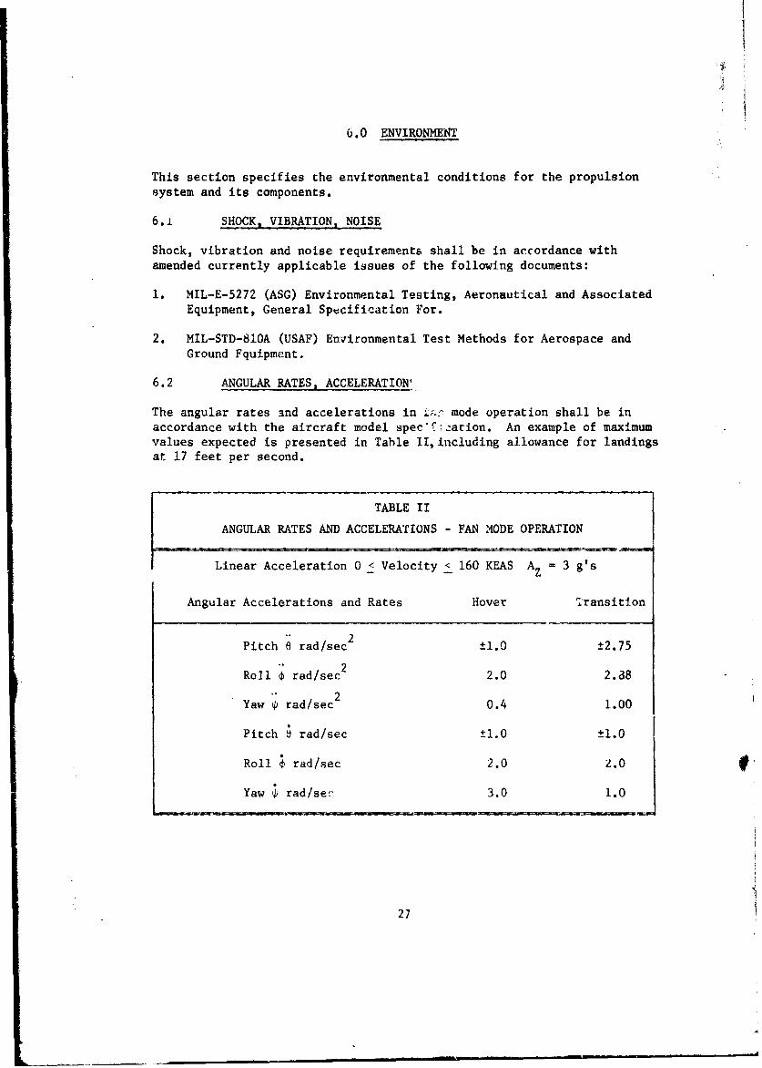
6.2 ANGULAR RATES, ACCELERATION'
The angular rates and accelerations in Z mode operation shall be inaccordance with the aircraft model spec.'farion. An example of maximumvalues expected is presented in Table II, including allowance for landingsat 17 feet per second.
TABLE II
ANGULAR RATES AND ACCELERATIONS - FAN MODE OPERATION
Linear Acceleration 0 < Velocity < 160 KEAS AZ 3 g's
Angular Accelerations and Rates Hover Transition
Pitch 8 rad/sec2 ±1.0 ±2.75
"2Roll l rad/sec 2.0 2.8
Yaw r rad/sec o.4 1.00
Pitch 0 rad/sec ±1.0 ±1.0
Roll ' rad/sec 2.0 2.0
Yaw ' rad/seý, 3.0 1.0
27
The structural design conditions for turbojet mode operation are:
a. Load factor of acting in combination with pitch accelerations of0 to radians per second squared.
b. Load factor of acting in combination with pitch accelerations of0 to radians per second squared.
c. Load factor of-- to __ acting in combination with a roll acceler-ation of -,radians per second squared.
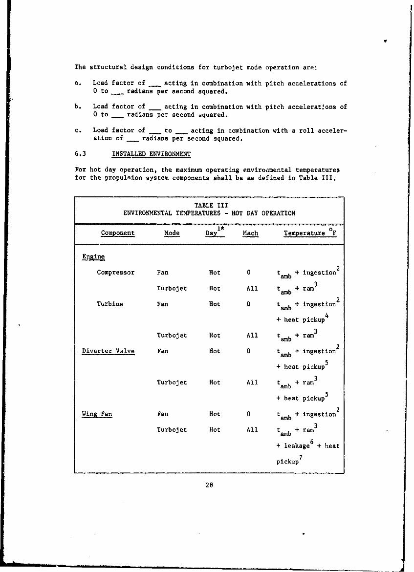
6.3 INSTALLED ENVIRONMENT
For hot day operation, the maximum operating enviroi.mental temperaturesfor the propul•ion system components shall be as defined in Table III.
TABLE IIIENVIRONMENTAL TEMPERATURES - HOT DAY OPERATION
Component Mode 1* Mach Temperature 0F
Engine
Compressor Fan Hot 0 tamb + ingestion2
Turbojet Hot All tamb + ram3
Turbine Fan Hot 0 tamb + ingestion 2
4+ heat pickup
3Turbojet Hot All tamb + ramn
Diverter Valve Fan Hot 0 tamb + ingestion2
5+ heat pickup 5
Turbojet Hot All tamb + ram3
+ heat pickup5
Wing Fan Fan Hot 0 tamb + ingestion2
3Turbojet Hot All tamb + ram
+ leakage6 + heat
pickup7
28
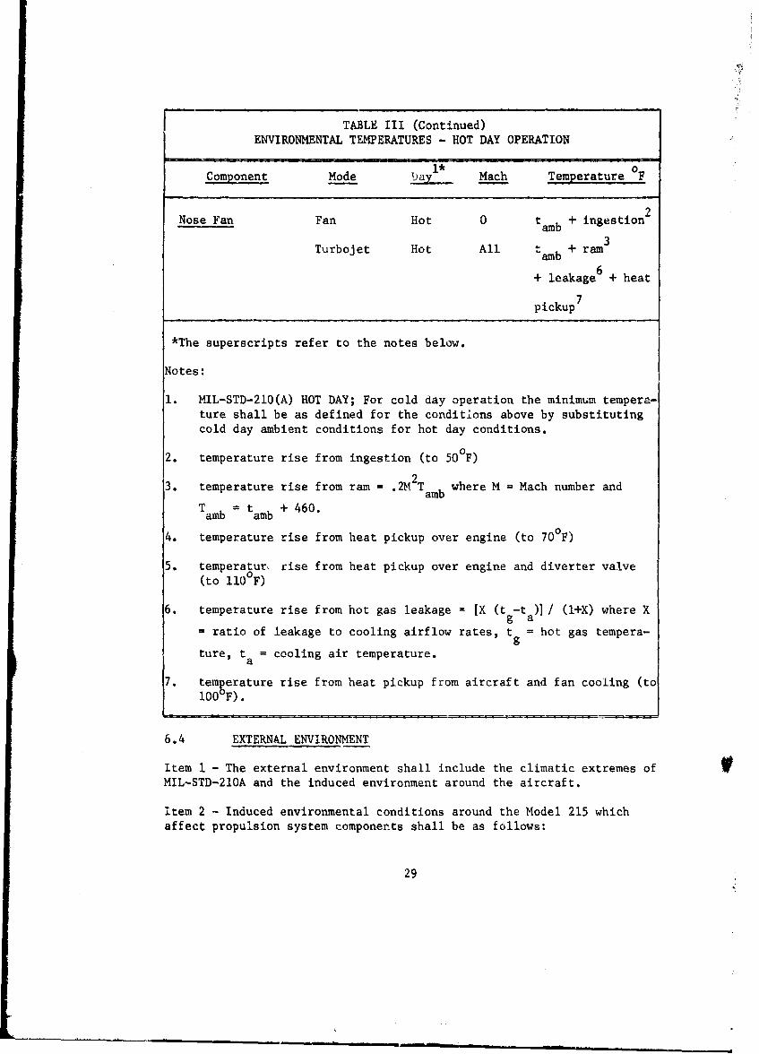
TABLE III (Continued)
ENVIRONMENTAL TEMPERATURES - HOT DAY OPERATION
Component Mode tiyl Mach Temperature OF
Nose Fan Fan Hot 0 tamb + ingestion2
3Turbojet Hot All amb + ram
+ leakage6 + heat
pickup7
*The superscripts refer to the notes below.
Notes:
1. MIL-STD-210(A) HOT DAY; For cold day operation the minimum tempera-ture shall be as defined for the conditions above by substitutingcold day ambient conditions for hot day conditions.
2. temperature rise from ingestion (to 500F)
3. temperature rise from ram = .2M2 Tamb where M =Mach number and
Tamb = tamb + 460.
4. temperature rise from heat pickup over engine (to 70°F)
5. temperatur, rise from heat pickup over engine and diverter valve(to 110°F)
6. temperature rise from hot gas leakage = IX (t -ta ) / (l+X) where X
= ratio of leakage to cooling airflow rates, t = hot gas tempera-gture, t = cooling air temperature.
a
7. temgerature rise from heat pickup from aircraft and fan cooling (to100 F).
6.4 EXTERNAL ENVIRONMENT
Item I - The external environment shall include the climatic extremes ofMIL-STD-210A and the induced environment around the aircraft.
item 2 - Induced environmental conditions around the Model 215 whichaffect propulsion system components shall be as follows:
29
a. Temperature
(1) Engine inlet air = Section 4.1.3, Item 1,
(2) Wing fan inlet aiL = t am + 100F,
(3) Nose fan inlet air = t mb + 30°F;
b. Vertical velocities during hovering in ground effect
(1) Engine inlet to 100 feet per second,
(2) Wing fan to 75 feet per second,
(3) Nose fan to 75 feet per second;
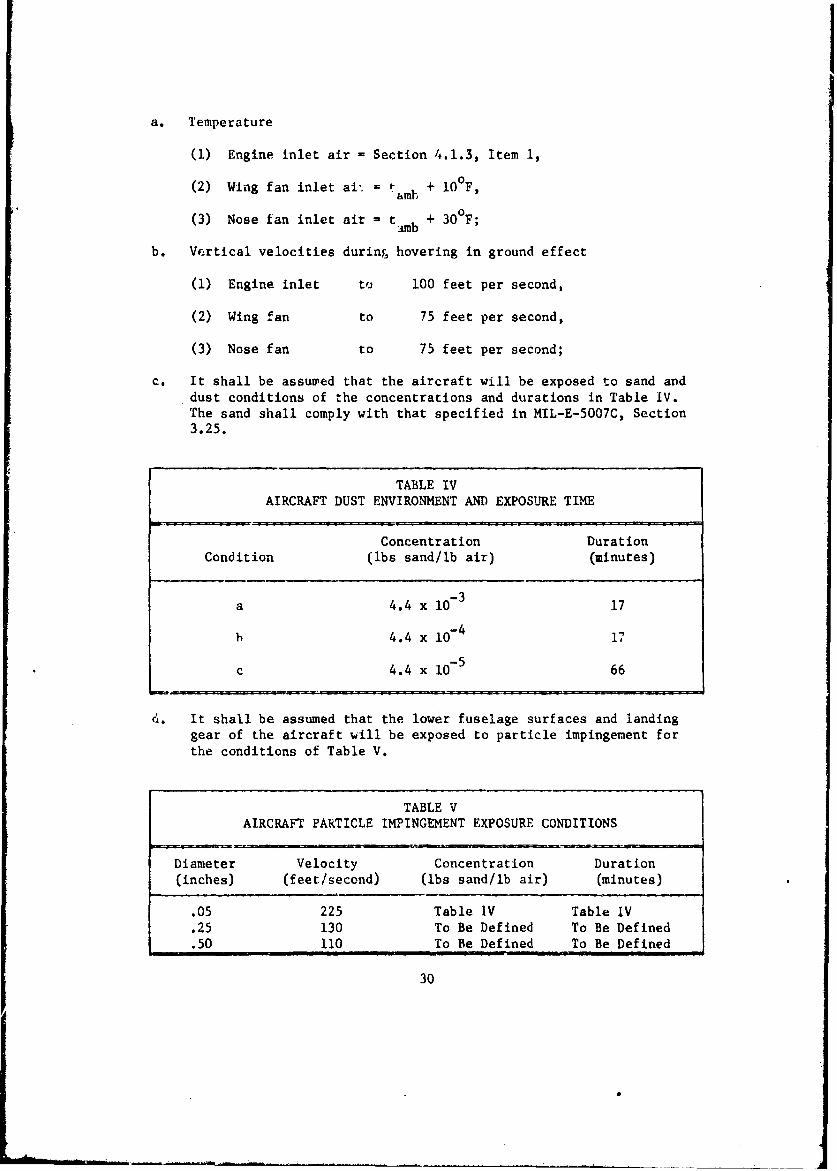
c. It shall be assured that the aircraft will be exposed to sand anddust conditions of the concentrations and durations in Table IV.The sand shall comply with that specified in MIL-E-5007C, Section3.25.
TABLE IVAIRCRAFT DUST ENVIRONMENT AND EXPOSURE TIME
Concentration DurationCondition (lbs sand/lb air) (minutes)
a 4.4 x 10⁻³ 17
b 4.4 x 10⁻⁴ 17
c 4.4 x 10⁻⁵ 66
4. It shall be assumed that the lower fuselage surfaces and landinggear of the aircraft will be exposed to particle impingement forthe conditions of Table V.
TABLE VAIRCRAFT PARTICLE IMPINGEMENT EXPOSURE CONDITIONS
Diameter Velocity Concentration Duration(inches) (feet/second) (lbs sand/lb air) (minutes)
.05 225 Table IV Table IV
.25 130 To Be Defined To Be Defined
.50 110 To Be Defined To Be Defined
30
7.0 RELIABILITY AND MAINTAINABILITY
Quantitative reliability and maintainability requirements shall equal or
exceed the -pplicable requirements of the military specifications of Sec-tion 2.1.] except as they may be modified by future studies.
31
" !I
II8.0 QUALIFICATION TESTS
8.1 STATIC OPERATION
Item I - The engine shall demonstrate satisfantory compliance with thefollowing:
a. Special requirements of this report.
b. Requirements of MIL-E-5009C except for the requirement of Item 4 ofthis section.
Item 2 - The diverter valve shall demonstrate satisfactory compliance withthe following:
a. Special requirements of this report.
b. Applicable requirements of MIL-E-5009C except for the requirement ofItem 4 of this section.
Item 3 - The nose fan and wing fans shall demonstrate satisfactory com-
pliance with the following:
a. Special requirements of this report.
b. Applicable requirements of MIL-E-5009C except for the requirement ofItem 4 of this section.
Item 4 - A propulsion system including engines, diverter valves, nose fan,and wing fans shall be installed in a simulated aircraft structure on avariable height instrumented test fixture and subjected to a test programequivale''t to a MIL-E-5009C Preliminary Flight Rating Test (PFRT).
a. Concurrent with the test program of Item 4a, the near and far fieldflow pattern characteristics, including temperature and velocityvectors, shall be established.
b. The propulsion system test program shall include test conditionscovering actual or simulated winds and their orientation, the com-plete range of operating controls, and any combination thereof in-cluding steady-state and transient operation.
c. Sufficient instrumentation shall be provided that complete steady-state and transienc propulsion system performance and the inducednear and far fie'd flow characteristics can be determined for eachtest condition.
d. A complete test report covering propulsion system performance, and thenear and far field flow characteristics for all test conditions shallbe furtnished to the airframe manufacturer for approval.
32
Item 5 - In addition to the distribution requirements of MIL-E-5009C,teRt reports shall be furnished to the contracting agency demonstratingpropulsion system component compliance with the following:
a. Special requirements of this report, and
b. Requirements of MIL-E-5009C.
8.2 WIND TUNNEL
Item 1 - Test Installation
Qualification of the lift fan propulsion system for fan mode forwardflight will require testing of the system in a suitable wind tunnel orsimulated crossflow conditions. While it would be desirable to qualifythe system by cesting it in a full-scale wind tunnel model, the minimuminstallation will require simulation of the fan inlets and closure doorsand the correct orientation of fan and engine inlets.
Item 2 - Forward Velocity
The lift fan propulsion system shall be qualified for fan mode flight upto the maximum fan mode flight speed of KEAS. Minimum test speedsneed not be lower than 40 KEAS.
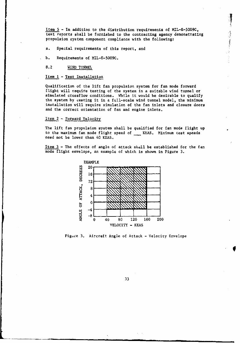
Item 3 - The effects of angle of attack shall be established for the fanmode flight envelope, an example of which is shown in Figure 3.
EXAMPLES20
16
S12
Z40
0
w -4
0 40 80 120 160 200VELOCITY - KEAS
Figure 3. Aircraft Angle of Attack - Velocity Envelope
33
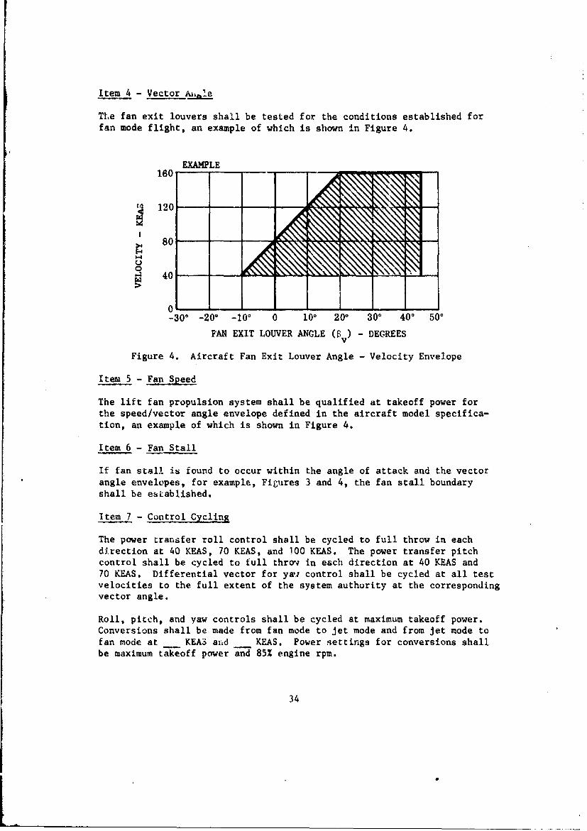
Item 4 - Vector al.e
The fan exit louvers shall be tested for the conditions established forfan mode flight, an example of which is shown in Figure 4.
EXAMPLE160
120
S 80 - -
40
01-300 -200 -100 0 100 200 300 400 500
FAN EXIT LOUVER ANGLE (ý ) - DEGREES
Figure 4. Aircraft Fan Exit Louver Angle - Velocity Envelope
Item 5 - Fan Speed
The lift fan propulsion system shall be qualified at takeoff power forthe speed/vector angle envelope defined in the aircraft model specifica-tion, an example of which is shown in Figure 4.
Item 6 - Fan Stall
If fan stall is found to occur within the angle of attack and the vectorangle envelopes, for example, Figures 3 and 4, the fan stall boundaryshall be established.
Item 7 - Control Cycling
The power transfer roll control shall be cycled to full throw in eachdirection at 40 KEAS, 70 KEAS, and 100 KEAS. The power transfer pitchcontrol shall be cycled to full throw in each direction at 40 KEAS and70 KEAS. Differential vector for ywa control shall be cycled at all testvelocities to the full extent of the system authority at the correspondingvector angle.
Roll, pitch, and yaw controls shall be cycled at maximum takeoff power.Conversions shall be made from fan mode to jet mode and from jet mode tofan mode at KEAS avd KEAS. Power settings for conversions shallbe maximum takeoff power and 85% engine rpm.
34
Item 8 - Maintenance and Inspection
Critical areas for maintenance and inspection shall be determined duringthese tests.
Item 9 - Endurance
Wind tunnel tests, in conjunction with the static tests, shall be of suf-ficient duration and shall entail sufficient cycling of all components toqualify the system for an initial 50-hour service life.
35
9.0 ACCEPTANCL TESTS
9.1 STATIC OPERATION
Item 1- The propulsion system components including the engine, divertervalve, nose fan, and wing fans shall demonstrate compliance with theacceptance test requirements of MIL-E-5009C.
Item 2 - Test data corrected to ARDC standard day demonstrating componentperformance over the complete operating range of all control settings andall combinations thereof shall be furnished to the airframe manufacturerfor each article accepted and delivered.
I
36
10.0 DATA
10.1 COMPONENT SFECIFICATIONS
A component model specification which complies with all applicablerequirements of MIL-E-5008C shall be .furnished to the a-rframe manu-facturer for each component including the engine, diverter -vaive, nosefan, and wing fans.
10.2 CbAPONENT DATA
Item 1 - Analytical and test data substantiating compliance with therequirements of this report shall be furnished to the airframe manu-facturer.
Item 2 - Upon request, propulsion system component test reports coveringPFRT, Qualification and Acceptance tests shall be furnished to the aiz-frame manufacturer.
10.3 PROPULSION SYSTEM DATA
Analytical and test data and test reports covering propulsion system per-formance tests shall be furnished to the airframe manufacturer,
37
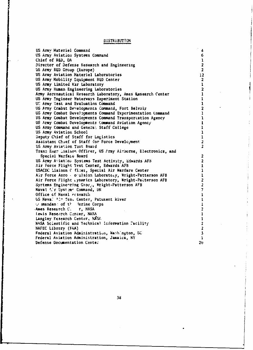
DISTRIBUTTON
US Army Materiel Command 4US Army Aviation Systems Command 6Chief of R&D, DA 1Director of Defense Research and Engineering 2US Army R&D Group (Europe) 2US Army Aviation Materiel Laboratories 12US Army Mobility Equipment R&D Center 2US Army Limited War Laboratory 1US Army Human Engineering Laboratories 2Army Aeronautical Resear:h Laboratory, Ames Ikesearch Center 1US Army Engineer Waterways Experiment Station 1U'_. Army Test and Evaluation Command 1US Army Combat De',elopments Commar.d, Fort Belvoir 2US Army Combat Deve) bpments Command Experimentation Command IUS Army Combat Developments Command Transportation Agency 1US Army Combat Developments Command Aviation Agency 1US Army Command and Genera"- Staff College 1US Army Aviation School 1Deputy Chief of Staff for Logistics 1Assistant Chief of Staff for Force Develcilment 2US Army Avia'.ion Test Boaid 2Tranz Erg. ýiaisoe Officer, US tray Air'orne, Electronics, and
Special Warfaie Board 2US Army A-:iat..oi1 Systems Test Activity, Edwards AFB 2Air Force Flight Test Center, Edwards AFB 1USACDC Liaison C fi-ex, Special Air Warfare Center 1Air Force Aero - o'ulsion Laboratoty, Wright-Patterson AFE 1Air Force Flight ynarics Labcratory, hright-Paz-terson AFB 2Sy.'tems Engincnring Giov*,, Wright-Patterson AFB 2Naval ',.*r Syst .in Command, ON 7Office of Naval ýcsearch 1US Nava: '- TesL Center, Patuxent kiver 1-. amandan" of tý izrine Corps I,Ames Research C'.. r, NASA 2
Leuis Reseairch Cknzer, NASA 1Langley FPesearch Center, NASt. 1NASA Scientific and Technical Inforration 7acility 2NAFEC Library (FAA) 2Federal Aviation Administratit, Wa.•h'.ngton, DC 3Federal Aviation Administration, Jamaica, NY IDefense Documentation Cente; 21
38
UNCLASSIFIED
DOCUMENT CONTROL DATA. fR & DS (Security flasillealon .. titl. SO* laa nd Ihnwe.id eietm.aff most be enItfid Whin m• Ow,all a" Is 0908eI10"jl
I. ORIGINATING ACTIVITY (CuOamg "diet) SO. mRpORT SECURITY CLASSIFICATION
Ryan Aeronautical Company Unclassified2701 Harbor Drive . GROUPSan Diego, California
C RE1PORT TITLE
SUGGESTED SPECIFICATION FOR A LIFT FAN PROPULSION SYSTEM
4, DESCRIPTIVE NOTES (2ý of MpWe mandn uhNwl dome)
Final Technical ReportS. AUTHORMIS) firw! n -a i haIitil, leas nawe)
Walter B. DavisBenjamin W. Ela
0. R2POeT DATE ML TOTAL NO. OF PAGSC 7b. NO. Or Rire
May 1969 455. CONTRACT o0 GRANT :*. 0& ORIINATOPPO REPORT NUMUERIS1
DA 44-177-AMC-345 (T)6. PROJECT NO. USAAVLABS Technical Rport 69-221F131201D161
a. S. OT1HER REPORT .40(5, (AAW akat -aE I 1 SOftbwa he lawsd
___ _Ryan Report No. 29469-310. OISITRIUIUION SITATEMENT
Each transmittal of this document outside the agencies of the US Government must haveprior approval of US Army Aviation Materiel Laboratories, Fort Eusti3, Virginia 23604.MI. SUPPLEMENTARY NOTES 11I. SPONSORING MILITARY ACTIVITY
U_. S. Army Aviation Materiel LaboratoriesFort Eustis, Virginia
.-5. ABSTACT
'This report presents propulsion system component design requirements believed to benecessary for successful development of operational lift fan aircraft. The work wasý'one under U. S. Army Aviation Materiel Laboratories (USAAVLABS) Contract DA 44-177-AMC-34S(T) from I July 196S to 1 March 1966 for the purpose of identifying lift fanairframe and propulsion system performance and ii ;tallation interfaces. Militaryspecification requirements are first examined for-applicability; they are then expandedor modified.
The requirements presented in this report reflect experience gained from the XV-5A liftfan aircraft flight test program.ý Requirements in areas such as flight dcsign loads,reliability and maintainability, and fan control rates are lacking in detail andauthority and will need additional definition as new criteria develop.
S....01473 ' LASS.ED -ev.eai %mew
W4. LINK A LINK 8 LINK cKEY WORDO ,
LOLIE WI ROLE - W- ROLE WY
Lift FanI
V/STOLHigh-Temperature Ducting
minm inn