Embed Size (px)
Citation preview

UNCLASSIFIED
AD NUMBER
AD405199
NEW LIMITATION CHANGE
TOApproved for public release, distributionunlimited
FROMDistribution authorized to U.S. Gov't.agencies and their contractors;Administrative/Operational Use; 27 MAY1963. Other requests shall be referred toAir Force Aeronautical Systems Division,Wright-Patterson AFB, OH 45433.
AUTHORITY
ASD, USAF ltr, 16 Jul 1974
THIS PAGE IS UNCLASSIFIED

NOTICZ: Ihen go0 '.m ent or other dr ngs, speci-fications or othez%. data are used for any purposeother than in conAction with a definitely relatedgovez'Mnnt PrOcur%=zmt operation, the U. S.(o3zV*Z nt therebY. incurs no responsibility, nor anyobligation iehatsOe-i*er; and the fact that the Govern-ment may have forzA_2Uted, furnished, or in any vaysuPPled the said .rving•s, specifications, or otherdata is not to be egardled by implication or other-
vise as in &ny =%=er licensing the holder or mayother person or cO-bpomtion, or conveying any ribhtsor pernission to Winwnufacture, use or sell mypatented invention that my in any vay be relatedthereto.

CCm
GENERAL OYNAMICS
ASTRCDNAUTICS
( A2136-1 M. 6161)
NO OTS

COMPILATION OF
MATERIALS RESEARCH DATA
A. F. Hooper
Fourth Quarterly Progress Report - Phase I1 March 1963 to 27 May 1963
Contract AF33(616)-7984Task No. 738103
27 May 1963
"THIS DOCUMENT MAY NOT BE REPRODUCED OR PUBLISHEDIN ANY FORM IN WHOLE OR IN PART WITHOUT PRIOR AP-PROVAL OF THE GOVERNMENT. SINCE THIS A PROGRESS
- REPORT THE INFORMATION HEREIN IS TENTATIVE AND SUB-JECT TO CHANGES, CORRECTIONS, AND MODIFICATIONS."

AR-592-1-374f1 December 1962
SJECT: Metallographic Examination of Radiographically DetectedDefects in Resistance Spot Welds in 0.010" thick 301Stainless Steel Centaur Intenrediate Bulkheads.
ABSTRACT: A number of resistance spot welds, which were removedfrom the longitudinal weld joints of both the structuraland spring ring bulkheads from the first Centaur C-2,(EIm No. 55-0501-2, originally assigned to F-2) werechosen for microscopic examination on the basis of radio-graphically detected defects on the periphery or withinthe spot welds. The main objective of this study is thecorrelation of the defect detected radiographically withthe type of defect actually found to be present by micro-scopic examination of a cross-section of the spot weld.
It was found that the location of the defect indicationrelative to both the light halo Image which encompassesthe resistance spot weld and the weld nugget image mayserve as an aid in the radiographic interpretation ofthe type of defect present. Any thinning or yielding ofthe sheet metal near the weld nugget appeared on the X-rayfilm as dark crescent-shaped images on the inner circum-ferential edge of the light halo image. Corrosion pitsnear the weld nugget were detected on the X-ray film asdark crescent-shaped images on the outer circumferentialedge of the halo Image. Scattered weld porosity was de-tected radiographically as dark irregular shaped imageswithin the weld nugget which appeared visually to consistof branch crscking.
Prepared by: Charles J.0- Kropp
APPROVED BY: 0 2 A.' "
Chief of Materials Research
AH:CJK:vmb
1

AR-592-1-371 411 December 196Q
TO: Distribution
FROM: MATERIALS RfEARCH GROUP, 59-1
SJBJECT: Metallographic Examination of Radiographically DetectedDefects in Resistance Spot Welds in 0.010" thick 301Stainless Steel Centaur Intermediate Bulkheads.
RlaNCES
(A) GD/Astronautics Report No. AA-61-0106
(B) "Leak Checking of C-2 Centaur Bulkhead", Report No. Al-9
(C) "Centaur C-2 Intermediate Bulkhead Evaluation", Report No. 55B 1471-1
(D) "Detection of Cracks Adjacent to Spotwelds by Radiography in ThinStainless Steel Sheet", Report No. 14RG-289
BACKGROUND
Tests Conducted on the First Centaur at AMR. After the firstCentaur C-2" and the Atlas IOl-D were mated at the Atlantic MissileRange, several attempts were made to tank the Centaur with propellants.These attempts were started on 19 June 1961 and continued until 10 Aug-ust 1961. During this period, several tanking tests were cancelled be-cause of malfunctions in the propellant storage tanks, propellant trans-fer system and in the Centaur.
Either liquid nitrogen or liquid oxygen was used to fill the aft tank onsix occasions; however, liquid hydrogen was used to partially fill theforward tank on only four of these tanking tests. The aft tank wasfilled with liquid nitrogen on two dates (19 June and 13 July 1961).Tanking tests on 6 July, 12 July, 27 July and 10 August 1961 involvedthe filling of the aft tank with liquid oxygen. On 10 August 1961, theforward tank was filled approximately 94% with liquid hydrogen, but thetest was stopped because a pressure of 6.8 psig was recorded in the for-ward tank. The normal pressure in this tank is 4.5 pug. During thistest the pressure in the aft tank decreased to l4.0 paig. The minimumpressure allowed in this tank it 13.8 paig. The above data vas obtainedfrom Report No. AA-61-0106.
*This Centaur was identified as EID No. 55-0501-1 and was originallyassigned to F-2 ("Centaur Commýttee Report on Materials and Fabrication",Lewis Research Center Report No. E-1976, 6 November 1962)
2

AR-592-l-37i13 December 196e
Based on the tests conducted at AMR, it was concluded that leaks In eithithe structural or the spring wing bulkheads were causing at least a por-tion of the difficulties encountered. In an attempt to pinpoint the ex.'location of the leaks, two Individuals from the Aerophysics Group at GD/jwere sent to AM to assist In this phase of testing.
During the leak checking investigation, the aft tank was purged withargon gas and the forward tank was purged with helium gas. The purgingwas repeated several times, but the pressures were not documented. Thebulkhead cavity was evacuated to an average pressure of 2 =, Hg afterboth tanks vere. filled (Report No. Al-9). The results of the leak checking investigation were not conclusive because it was found at a laterdate that one of the instruments used (an Aiphatron vacuum gage) vas not
-- "r-.purged°
Leak Checkin Tests Conducted At GD/Astronautics. After the formatank was cut and removed at appraxmately Station 30, the remaining po%tion of the aft section was then delivered to cD/A for a more completeinvestigation of the location of leaks in the bulkheads. A detailed docmentation of the procedure involved in this investigation is given inReport No. 55B lTI1-1. A ummary of the higher pressures used is givenbelow:
The aft tank was filled four times to an appreciablepressure: twice at 5 psig + 1 psig and twice at
ips÷ig+1 psig. The bulkWad cavity was also pressur-ized one time to 6 psig + 0.5 psig. Only helium gaswas used during these tests.
From this investigation, nine leaks were found In the structural bulkheibut no leaks were detected in the spring ring bulkhead.
After the completion of the radiographic inspection of both the structu~and spring ring bulkheads from the first Centaur C-2, the bulkheads andthe radiographic films were obtained by the Materials Research Group soto determine the actual internal conditions of snoe resistance spot welvhich, by the interpretation of the rdtiograths, contained defects. Thinternal conditions would be observed by microscopic examination of thecross-sectioned spot welds. The microscopic observation would then becorrelated with the imsges of the defects recorded on the radiographicfilms. The radiographic f ibs were exposed with a beryllium window tut
A similar Investigation was described in a previous report (M~-289) w1tcontained photomicrographs of cracks which develope adjacent to resisispot welds as a result of fatigue testing at -J-3 F. These fatiguecracks were recorded on the radiographic films a dense cresoent-shapedImages on the inner circumerential edge of the liiht halo of the spotweld.
3

AR-592-1-37i1U Docmbr l9Q
Radiographic inspectJon of the two Coentour bulkheads detected defects oanthe periphery and within the resistance spot welds which were not com-pletely similar in geomtry and Imge density "s those reported in M-2f89.
The •urpose of the present report Is to docaent the apes of spot welddefects which occurred In the first Centaur C-2 bulkheads by the conpar• -son of radlopnphic iam•s with the internal conditions of the cross-sectioned spot welds. The documentation of the results of this Investi-gation should be of some assistance In the interpretation of defectsfound in the radiographs of resistance spot welds.
PRtOCEDUFS
RAdiogra-ha of both the structural and spring ring bulkheads from thefirst Centaur C-2 were examined with particul"r attention given to thevarious types of defects present in the resistance spot welds. Thesedefects appeared as dark crescent-shaped. or irregular shaped images (likebranch cracking), respectively, on the periphery or in the center of theweld nugget.
At least one of each type of spot weld defect was chosen for microscopicexamination and the radiograph of the spot welds chosen was photographedat a magnification of 5X.
The spot welds which represented the dark crescent-shaped defect were pre-pared for microscopic exmination by cross-sectioning through the mecontsining the crescent. The samples were then ground and polished to thecenter of the crescent indication and examined microscopically. To accom-plish this task, the spot weld samples were carefully oriented with therespective radiographs.
The spot welds which contained the branch cracking type of defect were pre-pared for microscopic examination by performing the grinding sad polishingon the doubler sheet so that a plan view of the weld nugget was obtained.This method of sample preparation results in permitting observation of thespot weld in a plane similar in manner to the Imag of the weld as record-ed on the radiogrphic film. Grinding and polishing of the sales wasperformed in steps so that approximately 0.003" was removed. This step-vise procedure vwa continued until the defect was observed with a magni-tying lens.
RMSM
Spot Welds from the Structural Bulkhead. A sketch of the structuralbulkhead is incl.uded to show the locanion o two spot welds which vere re-moved from the bulkhead for microscopic exminnation of the defects, asrecorded radiographically (see Fig. 1).
AR-592-l-371&11 December 1969
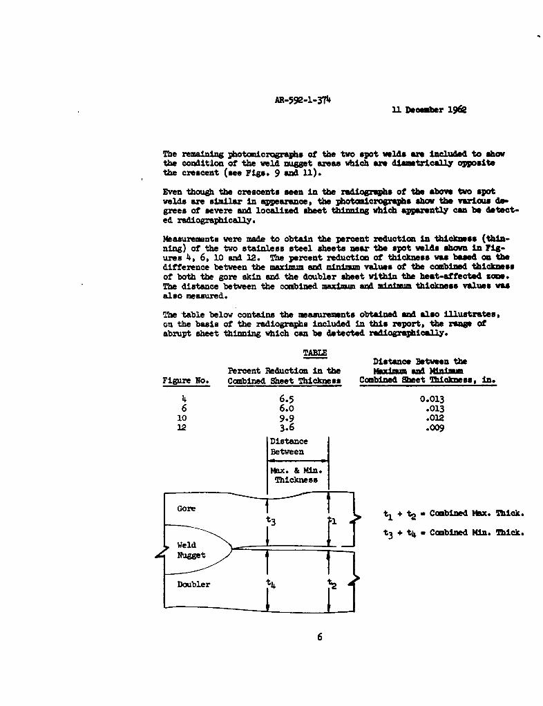
A reproduction of the radiograph, which shows the two spot welds thatwere cross-sectioned, is shown in Figure 2. The defects, which are seenas crescent-shaped images on the periphery of the weld nugets, wereinterpretated as crack Indications. These two defeat Images are ofapproximately equal density and seem to obscure a sector of the lighthalo Image.
Photomicrographs of the cross-sections obtained from the above two weldnuggets are shown in Figures 3 through 6. It can be seen that a crackdoes exist in one spot weld in the area which contained the crescentImage on the radiographic film (see Fig. 4). The photomicrograph of thecross-section through the second spot weld at the crescent area Is shownin Figure 6, but this spot weld does not contain a crack. The chiefsimilarity between these two spot welds is the almost equal amount ofthinning (yielding) of the gore skin. Thinning of the sheet would resultin a dark image (crescent) being recorded on the radiographic film. ItIs believed that, since the two crescent Images are of equal density, thesmall crack (11% through the loaded sheet), as seen in Figure 4, contribu-ted little, if any, density to the crescent, and was not actually detectedon the X-ray film. This belief is also based on the conclusions of theprevious investigation (NRG-289), which stated that a crack mast have alength greater than 15% through the loaded sheet if it Is to be detectedby radiographic inspection with a beryllium window tube.
The photomicrographa at IOOX, shown in Figures 3 and 5, are cross-sectionsof the same two spotwelds, showing the other ends of the nuggets dia-metrically opposite the side containing the crescent areas. It can beseen that these areas do not contain cracks and that no thinning of thesheets exists.
Spot Welds from the Upr% Rlng Bulkhead. A sketch of the springring bulkhead is also Included to show the location of the five spot weldswhich were also removed from the bhlkhead for microscopic examination ofthe defects as recorded radiographically (see Fig. 7).
The two spot welds shown in the radiograph in Figure 8 contain dark cres-cents on the periphery of the weld nugget; however, it can be seen thatthese crescents are finer in appearance than those shown in Figure 2. Theradiographic inspection roport concluded that these crescent images wereindicative of cracks at the nugget. Based on the finest of the crescentimages, It is believed that this conclusion is reasonable; however, thephotomicrographs showing the cross-sections at these areas proves thatsomething other than cracks in the stainless steel sheets were recorded onthe radiographs.
Photomicrographs of cross-sections of the two spot welds shown in Figure 8can be seen in Figures 9 through 12. The areas of these spot welds,which contained the crescents, actually show various degrees of thinninor yielding at the faying surface of the gore skin within the heat-affectedzone (approximately midway between the weld nugget and the carbide precipi-tation zone, (see Figs. 10 and 12).
5
AR-592-1-3T411 Decemiber 196e
The remaining photomicrographs of the two spot welds are included to showthe condition of the weld nugget areas which are diametrically oppositethe crescent (see Figs. 9 and 1I).
Even though the crescents seen in the radlogrqaba of the above two spotwelds are simila in appearance, the photomicrographs show the various de-grees of severe and localized sheet th'inig which apparently can be detect-ed radiographically.
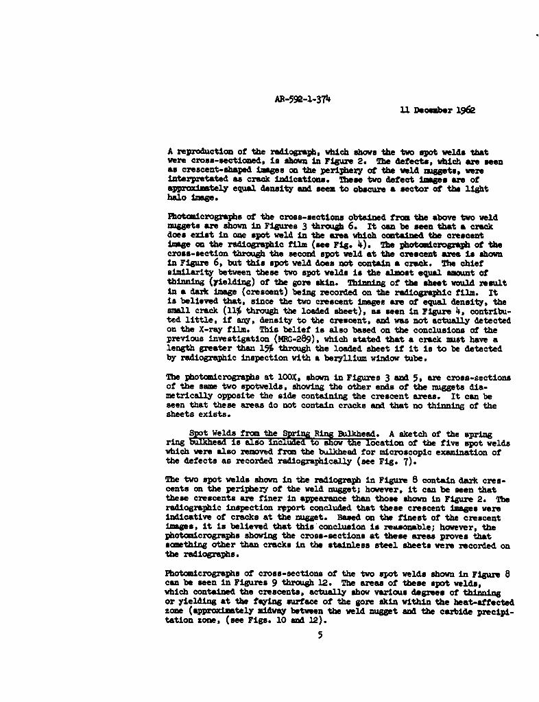
Measurements were made to obtain the percent reduction in thickness (thin-ning) of the two stainless steel sheets near the spot welds shown in Fig-ures 4, 6, 10 and 12. The percent reduction of thickness was based on thedifference between the maximum and minimum values of the combined thicknessof both the gore skin and the doubler sheet within the heat-affected sons.The distance between the combined maximum and minimum thickness values wasalso measured.
Tbe table below contains the measurements obtained and also illustrates,on the basis of the radiographs included in this report, the rongs ofabrupt sheet thinning which can be detected radiographically.
TABLEDistance Between the
Percent Reduction in the VAsXlm and MNniummFigure No. Combined Sheet Thickness Combined Sheet Thickness, in.
4 6.5 0.0136 6.0 .013
10 9.9 .01212 3.6 .009
DistanceBetween
Max. & MneoThickness
Gore ti + t2 a Combined Max* Thick.
t Wed t3t3 t4 1 a Combined Mine Thick.
Doubler tt4 j t2
6

AR-59e-1-3N 11 December 196
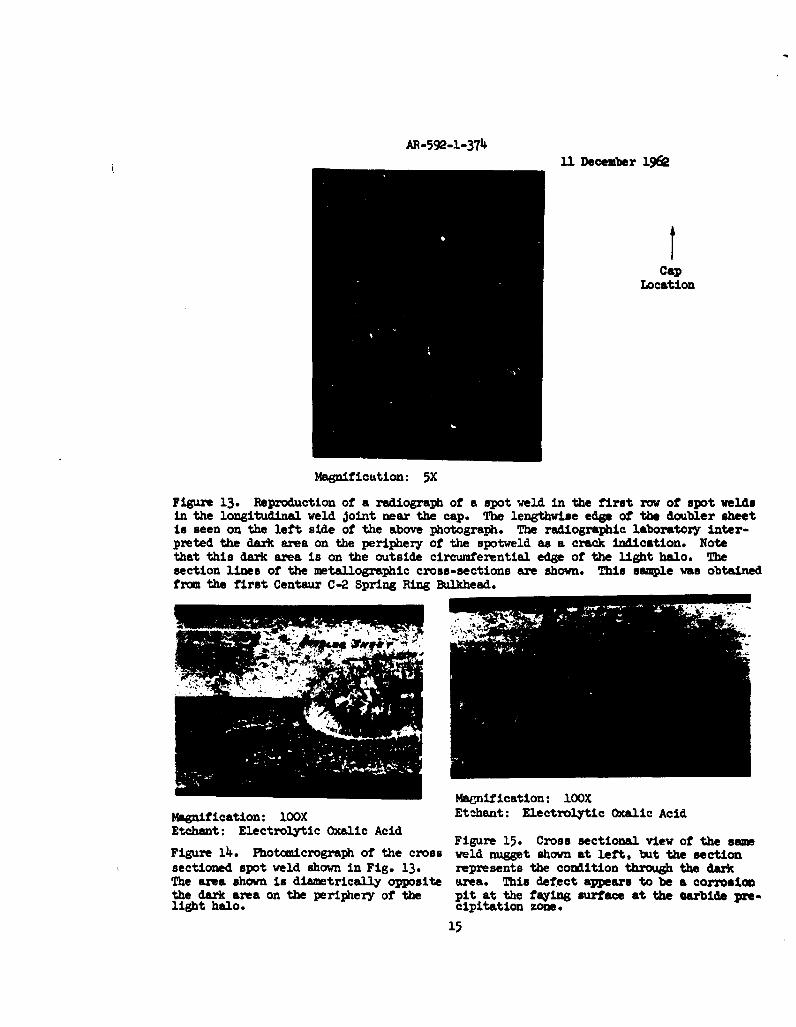
The radiograph reproductions shown in Figures 13 and 16 also contain de-fects on the periphery of the spot welds, however, It mn be seen thatthe dark defect images are located on the outside circumferential edge ofthe light halo. The previous spot weld defects were either located with-in the light halo area and obliterated a sector of the halo (see Fig. 2)or located on the inside circumferential edge of the light halo (see Fig.8).
The photomicrographs of the two spot welds shown in Figures 15 and 17illustrate that the radiographically detected defects are corrosion pitsat the faying surface of the two sheets in the cubtife precipitation zone.The resistance to corrosion attack is lowered in the carbide precipitationzone of a 301 stainless steel weld because the chromium content in theseareas is depleted during the heat cycle of welding. A corrosive fluidmay have become entrapped at the faying surface and the subsequent pitswere formed.
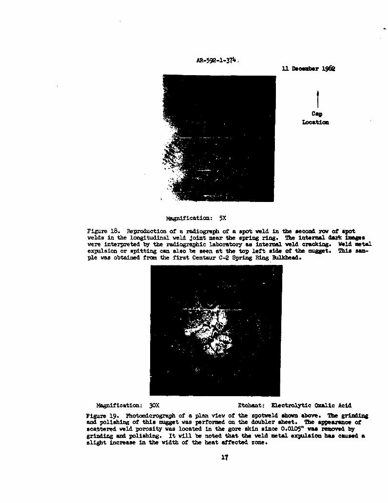
The last reproduction of a radiograph shows a spot weld with what appearsto be internal weld cracking along with weld metal expulsion or spitting(see Fig. 18). The photomicrograph of a plan view of this spot weld (Fig.19) indicates that the dark images within the weld nugget are actuallyscattered weld porosity. This photomicrograph also shows that the weldmetal expulsion has resulted in enlarging a portion of the heat-affectedzone. Note also that the two small dark images located on the inner cir-cumferential edge of the light halo correlate with the two small weld poreson the inner edge of the heat-affected zone.
CONCLUSIONS
Based on the observations made in this study, it is believed that theshape and density of the image of a defect, as recorded on X-ray film,along with the location of the defect image in relation to both the lighthalo and weld nugget images, may aid in the future radiographic interpre-tations of alleged defects in resistance spot welds. The locations of thedefect images may be divided into three categories along with the type ofdefect which may be present as follows:
1) Crescent-shaped dark Images at the inner circumferentialedge of the light halo may indicate a crack or severeand localized thinning or yielding in the load sheet(gore skin). It is believed at the present time thatthe thinning or yielding shown in this report was causedby localized overloading of certain spotwelds due to dis-continuity effects within the pressurized bulkhead andwas not produced at the time of welding. However, ifexcessive electrode pressure caused indentation of thewelded sheets, visual observation of the surface of theweld could be used to determine if a dark crescentX-ray image is due to electrode indentation. Based onevidence presented in this report, the defect would belocated midway between the weld nuget and the carbideprecipitation zone.
7

AR-59--3743.1 December 196e
2) Irregular shaped dark Images at the outer circum-ferential edge of the light h0lo indicates the possi-ble presence of a corrosion pit in the carbide precipl-tation zone. Corrosion pits In a 301 stainless steelweld are caused by a relativ&3.y long exposure time toa corrosive liquid. If corrcsion attack is not ob-served on the surface of the -eld, the corrosive liquidbecame entrapped at the fayinLa surface and pitted thesheets in the carbide precip:L-ttion zone.
3) Irregularly shaped dark Image a within the weld wigtmay indicate the presence of Internal weld porosity.These images may appear to be discontinuous vhich Isthe result of the formation or weld porosity underelectrode pressure.
It is believed that this investigatiora., al.ong with the one previouslyreferenced, should be beneficial in tbae radiographic inspection of resist-ance spot welds. It is recomnended tka3at further investigations of thistype be continued to obtain more case histories of defects in spot weldsand to attempt to determine the effect-s of the types of defects on themechanical properties of welded Jointm.
Distribution:
V. A. Babits 592-00 A. 1hrlich 592-10K. M. Boekamp 141-40 R. Kendall 758-00G. B. Branch 971-00 C. W. tukas 951-10E. D. Bryant 200-00 V. G. Wellquist 290-00L. V. Clements 967-20 H. E. Micken 290-30
L. Dasoff 141-4o0 W. G. Norris 961-40H. F. Dunholter 590-00 W . F. Radcliffe 960-00G. D. Davis 950-10 F. C. Rosacker 961-20A. L. Eakley 959-50 J_- D. Scherkenback 141-40E. R. Foor 290-40 J. E. Trader 959-00L. G. Granstedt 970-00 R . T. Vredenburgh 290-40J. P. Hopman 700-00 A- C. Waor 967-40
8

7 6
8r
Fig. 2
2._____________
At sptwZ mAtW inspct+
AR-592-l-374&11 December 1962
Caploation
Magnification: 5X
Figure 2. Reproduction of a radiograph of two spot welds which wereinterpreted by radiographic inspection as crack indications.The two spot welds shown above were located in the longitud-inal weld Joint near the cap. A portion of the cap can beseen at the top of this photograph. The spot weld on theright was in the first row of spot welds, while the spotweld on the left was in the third row of spot welds. Referto Figure 1 for the location of these two spot welds inrelation to the cap. The white circular Images were foundto be caused by small disks entrapped between the gore skinand the doubler and cap. The disks were identified byspectrographic analysis as being composed of a low meltingtemperature alloy, similar to Cerro Bend. This sample wasobtained from the first Centaur C-2 Structural Bulkhead.
10

U. December 1962
Magnification: 10OX iagnification: 10lOEtchant: Electrolytic Oxalic Acid Etchant: Electrolytic Oxalic Acid
Figure 3. Photomicrograph of the cross Figure 4. Photomicrograph of the cross-sectional view of the spot weld shown sectional view of the sam spot weld shownon the left side of the radiogiaph in at left, but at the opposite end of theFig. 2. The area shown is diametrically nugget and therefore indicates the condit-opposite the dark crescent. ion of the nugget at the crescent. The
crack shown is approxiately U.% throughthe gore skin. Note the thinning in thegore skin.
Magnification: lOOX Magnification: lOOXEtchant: Electrolytic Oxalic Acid Etchant: Electrolytic Oxalic Acid
Figure 5. Photomicrograph of the cross- Figure 6. Photomicrograph of the cross-sectional view of the spot weld shown on sectional view of the same spot weld shownthe right side of the radiograph in Fig. at left, but at the opposite end of the2. The area shown is diametrically oppo- nugget and therefore indicates the conditionsite the dark crescent. of the nugget at the crescent. Note the
nearly equal mnount of gore skin thinning,as seen here and Fig. 4.
11

S3.1 t~eo zbr 1962
FiG'xe j. The above sk~etch shows the 0oct10fonof .,.,two slote wiSsoni
8iue , 3.3, 3.6 end i8. The sket~oh reeft .. h. atif6R1
BuW.kheOil of the first Centaur C-2.
12

A'R-592-1-374.1 December 1962
Cap
location
Maganfication: 5X
Figure 8. Reproduction of a radiograph of two spot weldswhich were interpreted by radiographic inspect-Ion as cracks. The two spot welds shown abovewere located in the longitudinal weld Jointnear the cap. The nugget on the left was lo-cated in the first row of spot welds, whilethe nugget on the right was located in the thirdrow of spotwelds. The top edge of the four-inch wide doubler sheet can be seen at. the topof this radiograph. The section lines indicatethe planes of cross-sectioning for the metallo-graphic specimen. This sample was obtainedfrom the first Centaur C-2 Spring Ring Bulkhead.
13

AR-592-1-374
11 Decmbr 196e
Magnification: lOOX Magnlfication: 1OOXEtchant: Electrolytic Oxalic Acid ztchant: Electrolytic Oxalic Acid
Figure 9. Photamicrograph of the cross- Figure 10. Pbot•eiCOgrOp• Of the Cross-section through the nugget shown on the section of the same spot Veld shown atleft side of Fig. 8. The area shown In left but at the opposite end Of the 04a-diametrically opposite the crescent. get. This area represents the condition
of the nugget at the crescent. Note thethinning of the gore skin In the heat-affected zone at the faying surface.
Magnification: 1OOX Magnification: 10OXEtchant: Electrolytic Oxalic Acid Etchant: Electrolytic Oxalic Acid
Figure 11. Photomicrograph of the cross- Figure 12. Photomincrograph of the cross-section through the nugget shown on the sectional viev of the seame spot weld shownright side of Fig. 8. The area shown is at the left, but at the opposite end of thediametrically opposite the crescent. nugget. This area represents the condition
of the nugget at the crescent. Note thethinning of the gore skin in the heat-affected zone at the fayIng surface.
14I
AP-592-1-37T11 December 196Q
S~t
Caplocation
Maganification: 5X
Figure 13. Reproduction of a radiograph of a spot weld in the first row of spot weldsin the longitudinal weld Joint near the cap. The lengthwise edge of the doubler sheetis seen on the left side of the above photograph. The radiographic laboratory inter-preted the dark area on the periphery of the spotweld as a crack indication. Notethat this dark area is on the outside circumferential edge of the light halo. Thesection lines of the metallographic cross-sections are shown. This sample was obtainedfrom the first Centaur C-2 Spring Ring Bulkhead.
Magnification: lOOXMagnification: IOOX Etchant: Electrolytic Oxalic AcidEtchant: Electrolytic Oxalic Acid Figure 15. Cross sectional view of the samFigure 14. Photomicrograph of the cross weld nugget shown at left, but the sectionsectioned spot weld shown in Fig. 13. represents the condition through the darkThe area shown is diametrically opposite area. This defect appears to be a corrosionthe dark area on the periphery of the pit at the fying surface at the carbide pre-light halo. cipitation zone.
15

M-592-1-37411 December 19EQ
tCap
Location
Magnification: 5X
Figure 16. Reproduction of a radiograph of a spot weld in the second row of spotwelds in the longitudinal weld Joint near the cap. The dark area at the top of thenugget was interpreted by the radiographic laboratory as a crack. Note that thisdark indication is also located on the outside circumferential edge of the lighthalo (compare with Fig. 13). This simple was obtained from the first Centaur C-2Spring Ring Bulkhead.
Magnification: 30X Etchant: Electrolytic Oxalic AcidFigure 17. Photomicrograph of a plan view of the spot weld shown above. The grind-ing and polishing of this nugget was performed on the doubler sheet. This defect waslocated in the gore skin since 0.011" was removed by grinding and polishing. Whencompared to the radiograph, it is seen that this photomicrograph shows the nugget ina view which is turned slightly counterclockwise. This defect, like the one in Fig.15, also appeers to be a corrosion pit at the carbide precipitation zone.
16
AE-592-l-3T4 &3 D o r 19Q
CaLocation
Magnification: 5X
Figure 18. Reproduction of a radiograph of a spot weld in the second rov of spotwelds in the longitudinal weld Joint near the spring ring. The internal dark Imageswere interpreted by the radiographic laboratory as internal weld cracking. Weld metalexpulsion or spitting can also be seen at the top left aide of the nugget. This sam-ple was obtained from the first Centaur C-2 Spring Ring Bulkhead.
Magnification: 3OX Etchant: Electrolytic Oxalic Acid
Figure 19. Photomicrograph of a plan view of the spotweld shovn above. The grindngand polishing of this nugget was performed on the doubler sheet. The appearance ofscattered weld porosity was located in the gore skin since 0.0105" was removed bygrinding and polishing. It will be noted that the weld metal expulsion has caused aslight increase in the width of the heat affected zone.
17
11 Doemwhw 1962
1~OG~NL' 13YWIA!iOw DIML
Figure luaber MW M ~tive Disbar
2 N-iS87
3 Sf
4 XM-"~
5 M5t
6 W45
a ag1,i49e
9 K-5W7
10 M-5466
11 M-5828
12 U-51.67
13 U-54i95
11. M-5831
15 '4-5625
16 N-54i96
17 1-%m0
18 M-5622
19 m-5692
is