Embed Size (px)
Citation preview

UNCLASSIFIED
AD 408 3i4
DEFENSE DOCUMENTATION CENTERFOR
SCIENTIFIC AND TE()HNICAL INFORMATION
CAMERON STATION, ALEXANI'RIA, VIRGINIA
UNCLAS.SIFIED

NOTICE: When government or other drawings, speci-fications or other data are used for any purposeother than in connection with a definitely relatedgovernment procurement operation, the U. S.Government thereby incurs no responsibility, nor anyobligation whatsoever; and the fact that the Govern-ment may have forzmlated, furnished, or in any waysupplied the said drawings, specifications, or otherdata is not to be regarded by implication or other-wise as in any manner licensing the holder or anyother person or corporation, or conveying any rightsor permission to manufacture, use or sell anypatented invention that may in any way be relatedthereto.

ESD-TDR-63-34E S
OBJECTIVES GUIDE AND PERFORMANCE SPECIFICATIONS
FOR
TRANSPORTABLE COMMUNICATION FACILITY
STASK 4
CONTRACT AFI9(626)-5
ICS-63-TR-174
LI PREPARED FOR
AEROSPACECOM
DEPUTY FOR COMMUNICATION SYSTEMS424 TRAPELO: ROAD
WALTHAM 54, MASSACHUSETTS
LI
ITT COMMUNICATION SYSTEMS, INC.
fi PARAMUS, NEW JERSEY
U

IfilH TABLE ,OF CONTENTS
Section Page
PART A. OBJECTIVES GUIDE FOR TRANSPORTABLEH COMMUNICATION FACILITY
1.0 PURPOSE AND SCOPE I
2.0 GENERAL 1
3.0 FACTORS TO BE CONSIDERED 2
3.1 COMPATIBILITY 2
H 3.2 CHANNEL CAPACITY 4
3.3 STORAGE AND OPERATIONAL ENVIRONMENT 5
3.4 COMPLETENESS 5
3.5 MOBILITY, TRANSPORTABILITY, AND CONFIGURATION 5
3,6 IMPLEMENTATION TIME 6
3.7 PERFORMANCE 6
3.7.1 RANGE 7
3.7.2 POWER OUTPUT 8
3.7.3 MODULATION TECHNIQUES AND MODES 8
3.7.4 FREQUENCY COVERAGE-AND EMISSION 9
3.7.5 FREQUENCY STABILITY, CALIBRATION ACCURACY, 9AND CONTROL
3.7.6 SECURITY 9
3.7.7 ANTI-JAM CAPABILITY 9
3.7.8 CIRCUIT RELIABILITY 10
3.7.9 EQUIPMENT RELIABILITY AND MAINTAINABILITY 10
3.8 HUMAN ENGINEERING 10
3.9 ANTENNA SYSTEMS 11
3.10 PRIMARY POWER 13
3.11 AIR CONDITIONING AND HEATING 14
4.0 EQUIPMENT DEVELOPMENTS 15
4.1 TRANSMITTERS 15
4.2 RECEIVERS 15
4.3 FREQUENCY CONTROL 16
4.4 TUNING CONTROL 16
1 4.5 MULTIPLEX EQUIPMENT 16

TABLE OF CONTENTS (Continued)
Section Pae
4.6 POWER SUPPLIES 16
4.7 AUDIO PROCESSING AND CONTROL EQUIPMENT 17
4.8 TELEPRINTERS 17U4.9 CRYPTOGRAPHIC EQUIPMENT 17
4.10 SWITCHING EQUIPMENT 17
4.11 PERFORMANCE MONITORS AND TEST EQUIPMENT 17
4.12 CHANNEL QUALITY CONTROL EQUIPMENT 18
5.0 SUMMARY OF DESIGN OBJECTIVES 18
6.0 INTERIM SYSTEM DESIGN 20
PART B. PERFORMANCE SPECIFICATION FORTRANSPORTABLE, MODULAR COMMUNICATIONFACILITY
1.0 SCOPE 21
2.0 APPLICABLE DOCUMENTS 21
3.0 GENERAL DESCRIPTION 22
4.0 MODULAR CONCEPT AND CONFIGURATION 26
5.0 COMPATIBILITY AND STANDARDIZATION 34
S6.0 CHANNELIZATION 35
7.0 MAJOR COMPONENTS 37
f7.1 HF TRANSMITTER VAN 37
7.2 HF RECEIVER VAN 39
97.3 SWITCHING AND TECHNICAL CONTROL VAN 42
"7.4 CRYPTOGRAPHIC VAN 44
7.5 MESSAGE CENTER VAN 45
7.6 MICROWAVE/TROPOSCATTER VAN 46
7.7 UTILITY VAN 48
]7.8 INTER-VAN COMMUNICATION r 49
7.9 GAS TURBINE-GENERATOR SETS 50
7.10 ANTENNA ASSEMBLIES 51
7.11 AIR CONDITIONING, HEATING, AND HUMIDITY CONTROL 54
7.12 USER INSTRUMENTS 55
7.13 TECHNICAL CONTROL AND TEST EQUIPMENT 56
7.14 VANS 58
H]

[1TABLE OF CONTENTS (Continued)
SSection Page
8.0 IMPLEMENTATION 59
[9.0 CIRCUIT RELIABILITY 60
10.0 PROTECTIVE DEVICES AND ALARMS 60
11.0 HUMAN ENGINEERING 60
12.0 MOBILITY/TRANSPORTABILITY 61
13.0 CLIMATIC SERVICE CONDITIONS 62
L
oflIJ[
iv

hif LIST OF ILLUSTRATIONS
Figure Page
A-i COMMUNICATION LINKS 3
jB-i COMPLETE TRANSMOD COMPLEX 23
B-2 MODIFIED HF RECEIVER VAN 28
B-3 MODIFIED HF TRANSMITTER VAN 28
B-4 TWO VAN COMPLEX 29B-5 TWO VAN COMPLEX 29
L B-6 THREE VAN COMPLEX 30
B- 7 THREE' VAN 'COMPLEX 31
U B-8 FOUR VAN COMPLEX 32
B-9 FOUR VAN COMPLEX 33
B-iO TYPICAL CHANNELIZATION 36
I]
LIST OF TABLES
Table
B-I TRANSMOD EQUIPMENT TECHNICAL CHARACTERISTICS 24
ilv

0INTRODUCTION
Part A of this document contains an analysis of requirements for de-
jJpendable, transportable communication facilities that can be deployed glob-
ally during national emergencies and contingencies. It also provides engi-
neering standards and design criteria and recommends research and develop-
ment in support of such facilities. The design objectives and criteria
f]conform with the requirements for an improvement in the mobility, reliabil-
ity, and channel capacity of contingency communication facilities. They
are presented as guidelines to 4ssist in the realization of both short and
long term objectives. Performance criteria believed to be within the pres-
ent technology are presented in sufficient detail to permit conversion into
Vi equipment performance specifications.
Part B is a performance specification for a recommended transportable-
J modular (TRANSMOD) communication complex to fulfill the performance criteria
established in Part A. This complex is intended for the Air Force inventory
between 1965 and 1970. It represents concepts and equipments within the
present technology. Significant advances will continue to be made in com-
munication technology. Therefore, this performance specification should be
reviewed, evaluated, and modified as necessary prior to contract award to
avoid early obsolescence.
A cost analysis is not included as part of the performance specifica-
tion because costs will depend on the requirements included in the detailed
equipment specifications. However, an estimate indicates that a complete
TRANSMOD complex is not likely, to cost much less than $1,000,000.
n
H vi

p PART A. OBJECTIVES GUIDE FOR'TRANSPORTABLE COMMUNICATION FACILITY
1.0 PURPOSE AND SCOPE
SA review of existing and programed transportable facilities designed
for short, medium, and long haul point-to-point military communication re-
veals a conglomeration of HF, VHF, URF, LOS microwave, and troposcatter fa-
cilities. These facilities vary, in configuration and are designed for many
fldifferent capabilities and degrees of interface compatibility. The purpose
of this guide is to outline the factors that must be considered in the de-
sign of transportable communication facilities for contingency and limited
warfare activities and to present design criteria and objectives that should
be met to achieve the desired performance, compatibility, and quick reaction
capability.
2.0 GENERAL
It is doubtful if any one transportable facility could be designed tomeet the communication requirements of all types of global contingencies
and at the same time provide optimum performance. However, a logical ap-
proach is to design a family of subsystems, based on a modular design con-
cept, that could be assembled as the situation demanded. In the modular
concept, functional capabilities can be increased by adding modules or
"building blocks." This concept enhances the economy and flexibility of
transportable facilities for overall Air Force requirements. The modular
concept is therefore recommended for future limited warfare communication
jjsystems.The degree of flexibility, transportability, and relative freedom from
obsolescence achieved by the modular approach will increase compatibility,
improve quick reaction capability, minimize logistic support problems, sim-
plify training requirements, and result in an overall saving of funds. It
will also meet requirements that cannot be satisfied by any one transporta-
ble facility. Another advantage of the modular concept is the fact that
U all the equipment is not enclosed in one van that might be lost or severely
damaged in transit. Modules may be packaged so that an emergency operational
IIcapability can be provided even if one or more modules are lost or damaged in
.transit or after deployment. Each module should be capable of establishing
,communications on a limited basis during emergencies by means of a small HF
transceiver with an AIRCOM pivotal station. For example,.if the complete
[U

communication facility consists of an HF transmitting van, an HF receiving
van, and a message center van, all three vans should contain a small trans-
ceiver to provide the commander with emergency means of communicating with
Ii his headquarters if the high-power transmitter were not operational.
The modules must be designed to fulfill a specified set of existing
Sicommunication requirements but at the same time to resist obsolescence. A
careful analysis of techniques, equipments, and requirements is necessary
to achieve a suitable design for the basic van in. which interchangeable
communication modules may be installed.
.3.0 FACTORS TO-BE CONSIDERED
Commanders of forces operating within a contingency area require com-
munication facilities varying in complexity, and capability in accordance
with the tactical environment. The following factors should be considered
in the design of communication modules. They are presented here to serve
Ii as guidelines and objectives in the preparation of definitive performance
specifications and other procurement documents.
3.1 COMPATIBILITY
During overseas contingency operations it may be necessary for
the Air Force task commander to communicate with other activities as shown
in Figure A-1. Since the contingency situation cannot be predetermined,
the equipment required to provide the maximum flexibility and compatibility
must be included in the transportable facility. Figure A-1 indicates a re-
quirement for as many as eight separate circuits, although some contingen-
U cies may not require this many. (This is another argument in favor of the
,modular concept whereby only the required facilities would be deployed.)
Requirements will depend to a large degree on path distances,
terrain, and traffic volume. For example, elements of the unified command,
LI .the Army, and the local allied government may be located so that existing
landlines, microwave, or tropo circuits could be used. In the future, or-
biting satellite or moon relay communication links to CONUS may be available
thus eliminating the need for a long haul point to point HF circuit to the
DATACOM/AIRCOM.pivotal station. Manyrouting combinations are possible.
Therefore, a study of requirements is necessary to determine the best com-
binations of equipment in the transportable facility. Design objectives
should include sufficient equipment to provide a minimum of three HF cir-,
cuits which would provide simultaneous communication to three separate
.2

0
00JL) L00
I->LII
> IC
0i z0
-j 0
zz
I, ~-4~- U.
w Z
0- Ui -
JZtI -OWC
~ol ILJ
za
, i >~0

terminals and all devices necessary to assure compatibility with landline,
•II LOS microwave, troposcatter and G/A/G facilities.
The recommended approach is to provide a group of transportable
modules consisting of van-mounted HF, microwave, troposcatter, and G/A/G
equipment assembled to meet any contingency. All units should be packaged
in vans of a standard configuration, and such ancillary items as primary
power units, antenna supports, cables,.connectors, equipment. mounts; etc.,
should also be standardized.
3.2 CHANNEL CAPACITY
The trend in military communication is toward more and more cir-
cuits. This has resulted in frequency allocation problems within the RF
spectrum, especially, the HF portion. A common misconception is that trans-U portable communication facilities deployed in a contingency area can use
frequencies almost at will. In fact, permission to use radio frequencies
must be obtained by U.S. forces from the local U.S. theater command that,
in.turn, must obtain approval from. the host government. Frequencies cleared
.for bandwidths of 12 kc and 6 kc are virtually impossible to obtain on the
short notice associated..with contingency operations.
If more circuits are to be made available, they, must be obtained
by more efficient utilization of the available spectrum. This dictates the
need for a comprehensive study and subsequent R&D action directed toward the
V development of techniques which will provide a greater number of channels
and increased data rates with no increase in bandwidth requirements and theUdevelopment of transportable equipments incorporating the necessary features,
The efforts should be directed. toward maximum utilization of the regular
S3'kc voice frequency channel.
A. high percentage of all Air Force communications during a limited
T warfare situation will continue to be by voice. A significant increase in
L the number of voice channels may be realized by employing analogspeech com-
pression and vocoder techniques which will reduce the bandwidth of normal
Lspeech~signals. These compressed signals may be multiplexed onto the regu-
lar 3 kc band to provide two or more speech channels with no increase in
Soverall bandwidth. More efficient utilization of the spectrum may also be
achieved by applying advanced digital techniques for the transmission and
{• reception Qf' data. By employing multiplex equipment, the regular 3jkc
channel will support. various combinations of data rates fromi 600 to 2400 bps.
U4

e 3e 3 STORAGE AND OPERATIONAL ENVIRONMENT
'The world political situation between,1965 and 1970 indicates theneed for storing transportable communication facilities in strategic posi-
tions ready for deployment in limited warfare operations. The facilities
may be placed in outside storage areas in a wide variety of climatic con-
ditions for up to two years; therefore, they must be designed- to withstand
such storage and be fully, operational on short notice. They must also be
designed to withstand the operational effects of shock, vibration, high hu-
midity, rain, snow, ice, winds, blowing sand and dust. salt atmosphere,
.salt spray, fungus. and high to low ambient temperature.
3.4 COMPLETENESS
These facilities must operate for several days with no outside
.I! support and for weeks or months with a minimum of outside support. There-
fore, the facility should contain at least the following:
P a. Tools and test equipment necessary for installation, opera-
tion, maintenance, and calibration.
.b. Supplies such as paper, pencils, typewriter ribbons, etc..,
necessary for normal operation.
*c . Spare parts, modules, and subassemblies necessary for main-
tenance.
d. Frequency control devices for the entire band over which the
facility is expected to operate.
e. A primarypower source and necessary fuel as required.
3.5 MOBILITY, TRANSPORTABILITY, AND CONFIGURATION
.The modular concept will provide a family of facilities capable
of being assembled and deployed as needed and augmented to achieve the de-'
gree of mobility, and operational capability required. Communication facil-
ities may be packaged in relatively small units transportable by small cargo
aircraft. These small packages could be fitted with removable or retracta-
ble wheel assemblies to permit towing. These smaller modules could also be
designed to permit loading on trucks. Large facilities such as those mounted
in vans and semi-trailers have a limited transportability and can be deployed
HI to relatively, few air bases by large cargo aircraft. In addition, they are
usually not capable of cross-country mobility.
U.

Another very important consideration is helicopter transporta-bility. Contingencies are likely to occur in relatively undeveloped, back-
ward and remote areas where quite often the helicopter is the only means of
transport. Therefore, consideration should be given to size and weight limi-
tations of helicopters.
An analysis of existing and planned aircraft and ground vehicles
is necessary so that optimum weight and dimensions for communication facili-
(I ties can be determined.
3.6 IMPLEMENTATION TIME
To maintain a quick reaction capability it is necessary to keep
the time required for setting-up contingency communication facilities to a
minimum. A general rule is to limit the complexity of the facility to the
i|i degree that it may be set up and on the air within ten hours or less. Com-
ponents and ancillary items associated with the facility should be stowed
H within the shelter in a manner to permit easy removal. In addition, they
should be arranged so that a minimum of unpacking time is required. All
1hardware and tools necessary for assembly should be readily available.
3.7 PERFORMANCE
Since the facility may be celled upon to prcide communication
nearly anywhere on the earth, it is necessary to determine general require-
ments for a wide range of path lengths and geographical locations. Many of
B the equipments and design and installation techniques associated with theengineering of fixed plant communication systems cannot be applied to trans-
U portable facilities. The temptation is to provide the greatest power possi-
ble since path lengths may be as great as several thousand miles; to provide
the maximum number of channels since the quantity desired usually exceeds
H those available; and to provide elaborate antenna systems and redundancy to
insure reliability. In the design of transportable facilities, this is not
the most practical approach because consideration must be given to size,
weight, mobility, complexity, logistic support, etc. Security, survivability,
LIcompatibility, and ability to withstand the transportable environment are
considerations equally as important as the ability to communicate efficiently.
The following performance criteria and guidelines are presented to serve as
a basis for the design of transportable communication facilities.
Ii 6

3.7.1 Range
The communication requirements may be classified according
to path length as: very short,.short, medium, long, and ground-air-ground.
Very short distance circuits vary from a few hundred yards
t[1a few miles and may include inter-van or intersite communication~that
can be provided by, radio, wire, cable, or man-portable microwave equipment
similar to the AN/TRC-56 and AN/TRC-92.
Short distance circuits have a maximum path length.in the
order of 30 miles and may include intersite paths, links from transportable
comm~unication,centers to a ground based, mobile satellite communication van;
and links to other commanders. Such links can be provided by transportable
-microwave equipment such as the AN/GRC-66.
ii Medium distance circuits are between 30 miles and about
150 miles that can be satisfied by transportable troposcatter equipment
similar to the AN/TRC-90, AN/TRC-66, and AN/GRC-66.
Long distance circuits are in excess of 150 miles and may
include circuits from the contingency area to CONUS via DATACOM/AIRCOM fa-
cilities, orbiting communication satellites, or moon relay, facilities.
It is conceivable that all operational elements may be po-
sitioned so that most of the necessary communications links could be pros-
vided by employing transportable microwave and tm poscatter facilities with
Li a minimum number of HF links. On the other hand, some contingencies may re-
quire extensive use of HF links combined with low-power, man-portable micro-nwave equipment for very short distance links and.no regular microwave or
troposcatter equipment.
[1 To meet.these widely varying requirements, it is essentialU for the Air Force to develop a complete family of transportable modules
which will satisfy, the requirement for various numbers of circuits over
• various path lengths.
In addition to HF, c-ommunication facilities such as micro-
wave LOS and troposcatter are required to provide circuits in one direction
.or possibly two directions simultaneously, and only one or two antenna sys-
tems are associated with each set. However, many contingency and limited
warfare operations may.require two-way, HF circuits in three different direc-
tions simultaneously. Based on these requirements, the following family of
.vans could be designed for assembly and deployment to satisfy, the communica-
tion, requirements of most contingency and limited warfare operations:
".7

HF transmitter van (3 circuits, 3 directions)
HF receiver van (3 circuits, 3 directions)
Microwave/troposcatter van (24.Channels)
Li Message center van
Cryptographic van
Utility van (maintenance and spares)
Switching and technical control van
.3.7.2 Power Output
The RFpower output of communication equipment is a very
important consideration if reliable communications are to be realized. Many
factors favor utilizing the maximum power that can be packaged into a trans-
portabl.e configuration. For example, it may be determined that an HF trans-
mitter power output of 5 kw with present type transportable antennas would
be adequate for most paths but 10 kw would be desirable to provide an extra
j I•_margin of confidence. However, a decision t6 utilize the higher power must
be given, careful consideration to determine how it Tqill affect the remainder
of the system. For example, the higher power units are heavier and require
a heavy duty antenna system capable of handling the RF power. In addition,
primary power requirements are increased with consequent additional require-
ments for POL support. RFI and self-jamming problems may also be increased
by using higher power.
A better approach to reliability is to increase the effec-
tive radiated power. One method of achieving this is by development of more
Sefficient antenna systems than are presently available for transportable use.
The RF power outputs for the various media indicated below
Sshould be adequate for reliable communication in most contingencies.
Very short distance portable microwave: in the order of.1 watt
SShort distance microwave: aminimum of I watt
Medium distance troposcatter: a minimum of I kw
Medium and long distance HF SSB: 500 watts, .2.5 kw, and5 kw selectable by the operator
Ground-aerosp~ace-ground VHF and UHF: 20 to 50 watts
3.7.3 Modulation Techniques and Modes
In general, HF equipment should be capable of operating
in the SSB,. ISB, CW, and FSK modes as well as compatible AM; microwave and
troposcatter equipment in the PCM/FM, PAM/FM, or SSB modes; and G/A/G in
8

SSB, ISB, AM, or FM. The types of circuits required include voice. data,
teletype, and graphics. To permit more efficient use of the overall spec-trum in connection with HF, VHF,, UHF., and SHF., it is recommended that fur-
jther efforts be directed toward developing and/or applying modulation tech-
niques which will enable passing increased information over the regular 3 kc
voice frequency channel.
3.7.4 Frequency.Coverage and Emission
Facilities designed for contingency, operations should in-
clude equipment capable of operation in the assigned military bands associ-
ated with HF, VHF, UHF, microwave, troposcatter, and communication satellite
Sequipment.3.7.5 Frequency Stability, Calibration Accuracy, and Control
iL~1 High-frequency, receiving equipment should be designed for
a frequency, stability of I part in 108 or better by employing frequency syn-
[j thesizers tunable in 100 cycle increments over 2 to 30 mc. This degree of
stability is required in the interest of high circuit reliabilitywhen used
to receive signals from an equally stable transmitter; however,.it is rea-
sonable to expect that transportable facilities may be required to net with
ground facilities which have not been stabilized to this extent and with
airborne facilities which will appear to the receiving equipment to drift
because of doppler shift caused by the relative motion. Therefore, a form
of automatic frequency control (AFC) should be included. Transmitting
equipment should have the same order of frequency stability as receiving
equipment. The stability of microwave and troposcatter equipment should
be 1 part in 10 or better.
3.7.6 Security
Secure circuits are of primary importance during limited
warfare operations since traffic originated by the commander utilizing the
transportable facility involves critical information pertaining to movement
of forces, plans, intelligence reports, etc. Therefore, secure teletype,
data, and voice circuits are considered essential in the design of trans-
portable facilities.
3.7.7 Anti-Jam Capability
Consideration must be given to the electromagnetic environ-
ment within which the transportable facility may be deployed and the proxim-
ity, to the enemy so that design objectives may be established to incorporate
9

some of the anti-jam techniques now under development. This effort should
include an analysis of equipment design and human engineering problems as-
sociated with anti-jamming operational techniques. Associated with jamming
{is the possibility, of interference. Transportable facilities may be placed
in operation relatively close to other electromagnetic radiating equipments
such as VHF/UHF, radar, microwave, troposcatter, power motors, generators
and teletype equipment. Further R&D effort should be devoted to the devel-
•I opment of anti-jam modulation and demodulation techniques and devices.
3.7.,8 Circuit Reliability
HF circuits should operate over path lengths from approxi-
mately 100 to 3000 miles with a mean overall path efficiency of 90%. The re-
liability of other types of circuits should approach that achieved by com-
parable fixed plant systems. This means that the equipment must be designed
with adequate power, good antenna gain and efficiency, and a safety, margin
U which will assure reliable circuits even though the siting, assembly, ori-
entation, etc., may not be optimum. Allowances should be made for the fact
that relatively, unskilled personnel may set up the equipment.
.3.7.9 Equipment Reliability. & Maintainability
Reliability is frequently thought of in terms of mean time
between failures (MTBF). Though this is important, it is by no means suffi-cient to characterize total system reliability. In addition to MTBF, equip-ment reliability involves ease of repair and simple preventive maintenance
procedures. Good system design includes packaging the equipment for easy
flmaintenance. Transportable facilities must be designed to be maintained
by personnel without highly specialized training. Electronic and electri-
cal equipment should be designed to fail-safe. Reliability requirements
should include design criteria for rapid trou :e~hooting and repair tech-
niques. Technical and quality control equipment and procedures should be
as simple as practicable. Self-check maintenance equipment should continu-
ously monitor the condition of critical equipment and actuate audio and vis-
ual alarms when equipments fail or approach tolerance limits. Standby equip-
ment should automatically be switched into service. Design should be such as
to permit personnel to accomplish repair by replacement of plug-in modules.
3.8 HUMAN ENGINEERING
1 For the man-machine interfaces, all readouts and displays should
be as simple as possible and designed for maximum clarity. Operator controls
U 10

should be few in number and functionally grouped. Color-coding and specially
B shaped controls should be used. The facility should be simple to set-up, op-
erate, maintain, and repair. Immediate access to communication circuits
[Ishould be obtained by merely pushing a button or operating a switch.
Adequate space should be provided for operating personnel to per-
{j form, their duties. Operating space within the vans should be designed on
the basis of 15 square feet of floor space per operator.
Unfavorable environment can cause discomfort and fatigue. The
following table lists the level or tolerance ranges for the most important
internal environmental conditions in transportable communication vans:
Condition Level or Range
Light 30 ft candles, minimum (at desk height)
[Noise 50 db above ASA ref (max)
Air velocity 100 ft/min (max)
Temperature 700 to 800 F
Humidity 40% to 60%
13.9 ANTENNA SYSTEMS
Highly transportable, broad-band antennas and light- weight antenna
supports capable of rapid erection are required. There are economic advan-
U• tages in using higher gain antennas and less powerful transmitters. Within
limits, increased radiated power in a given direction can be achieved more
economically by use of efficient high gain antennas than by use of higher
transmitter power.U The desired angle of radiation of HF antennas is a function of
path length and should be designed into the antenna system for optimum per-
formance. This is not difficult when designing antennas for fixed point to,.
point circuits but is more complex when the antenna is to be transportable
and must operate over a very wide frequency band, over varying path lengths,
in different geographical locations. This capabilty could be achieved by
providing a group of antennas, but that is contrary to the concept of limit-
ing size, weight, and volume. The design objective is to provide a single,light-weight transportable HF antenna that will provide relatively high take-
off angles for lower frequencies and short paths, and lower take-off angles
for higher frequencies and long paths. This should be accomplished with a
minimum gain of 5 db over the frequency range of from 2 to 30 mc.
8 1
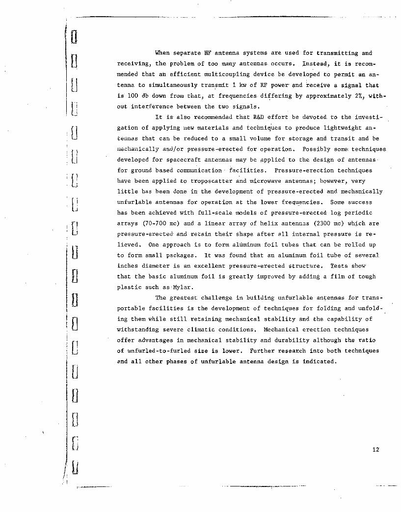
When separate HF antenna systems are used for transmitting and
receiving, the problem of too many antennas occurs. Instead, it is recom-
mended that an efficient multicoupling device be developed to permit an an-
tenna to simultaneously transmit 1 kw of RF power and receive a signal that
is 100 db down from that, at frequencies differing by approximately 2%, with-
out interference between the two signals.
it is also recommended that R&D effort be devoted to the investi-
gation of applying new materials and techniques to produce lightweight an-
U tennas that can be reduced to a small volume for storage and transit and be
mechanically and/or pressure-erected for operation. Possibly some techniques.
developed for spacecraft antennas may be applied to the design of antennas.
for ground based communication facilities. Pressure-erection techniques
have been applied to troposcatter and microwave antennas; however, very
little has been done in the development of pressure-erected and mechanically
unfurlable antennas for operation at the lower frequencies. Some successLi has been achieved with full-scale models of pressure-erected log periodic
f arrays (70-700 mc) and a linear array of helix antennas (2300 mc) which are
U pressure-erected and retain their shape after all internal pressure is re-
lieved. One approach is to form aluminum foil tubes that can be rolled up
to form small packages. It was found that an aluminum foil tube of several
inches diameter is an excellent pressure-erected structure. Tests show
[Ithat the basic aluminum foil is greatly improved by adding a film of tough
plastic such as-Mylar.
The greatest challenge in building unfurlable antennas for trans-
portable facilities is the development of techniques for folding and unfold-
ing them while still retaining mechanical stability and the capability of
withstanding severe climatic conditions. Mechanical erection techniques
offer advantages in mechanical stability and durability although the ratio
of unfurled-to-furled size is lower. Further research into both techniques
and all other phases of unfurlable antenna design is indicated.
B 12

3.10 PRIMARY POWER
Continuing efforts must be directed toward designing communica-
tion equipment with low primary power consumption so that the sizes and
weights of both the equipment and the supporting primary power source may
be held to a minimum. At the same time, R&D efforts must be devoted to re-
ducing the size, weight, and volume of power generating equipment to keep
abreast of communication equipment developments. In fact, major improve-
ments in electronics equipment to reduce weight and volume for transportable
applications are without significance if this is not accomplished. For ex-
ample, the power generation and distribution equipment associated with many
U existing transportable communication facilities exceeds the supported elec-
trical and electronic equipment in size, weight, and volume.
Specific areas recommended for study are' the application of solid
state devices to permit low primary power consumption and the application of
primary power sources with a high power-to-weight ratio. It is unlikely
that all communication equipment will be solid' state during this' time frame;
however, a combination of electron tubes and solid state devices operated
from a combination of AC and DC sources to achieve a net reduction in primary
power requirements should be considered. Many R&D programs are attempting to
develop lightweight, reliable, primary power sources for space programs as
well as military air and ground support. The following power sources and
V prime movers may be applicable to transportable service: advanced design
gas turbines, Stirling cycle engines, and fuel cells.
Four hundred cycle primary power sources have been employed with
some transportable facilities in an effort to hold volume and weight to a
minimum or to operate with equipment originally designed for airborne service.
In fact, there have been recommendations to standardize on the combination of
400 cycle communication equipment and 400 cycle power sources for transport-
able applications. Solid state technology should ultimately produce equip--
ment substantially reduced in weight and volume. Therefore, it is considered
more practicable at this time to concentrate efforts on solid state devices1.and primary power sources rather than make the transition from 60 cycle AC,
to 400 cycle AC, and then to the solid state DC combination. During the in-
terim, the combination of 400 cycle equipment and 400 cycle power sources
may be practicable for certain transportable applications if the desired degre
13

of reliability is achieved. Maximum use should be made of avgi-labie--s6ld_
I lstate communication and power supply equipment during this interim period
to keep weight and volume to a minimum.
The 400 cycle source may consist of a gas-turbine engine driving
a 400 cycle generator that can furnish AC power directly to AC operated com-
munication equipment. DC power would be furflished through a solid state
L charger and battery combination and through DC to DC solid state converters
that convert the low voltage DC battery power to high voltage DC. When 400
cycle primary sources are used with conmunication facilities, most of the
communication equipment should be designed to operate directly from 400
U cycles. However, if it is necessary to use some devices that operate from
60 cycle AC only, solid state frequency converters can be installed to con-
Vert the 400 cycle primary power to 60 cycle primary power.The advantages of 400 cycle power units are higher power-to-weight
9 ratio and simplicity. Improvements required in the gas turbine are noise
Li reduction, increased efficiency, lower fuel consumption, and lower cost.
Diesel. driven 60 cycle generators may be'the most practicable for some ap-
plications during this time frame, Present advantages of the diesel engine
over the gas turbine engine are lower cost, lower fuel consumption, longer
H life expectancy, and quieter operation. Also, more existing equipment can
be operated from 60 cycle AC power.
3.11 AIR CONDITIONING AND HEATING
Air conditioning and heating facilities are usually an integral
part of overall transportable facility design. In view of the anticipated
areas of operation, humidity control should also be included in transportable
communication facilities for limited warfare. Heating may be accomplished
by electric or multifuel heaters either incorporated in the air conditioning
system, in separate portable units, or a combination of both. Subjects re-
quiring further investigation are:
a. Investigate the feasibility of circulating conditioned air
under pressure through equipment racks and cabinets for cooling equipment,
with a separate cooling system for personnel.
b. Include humidity control devices capable of efficient opera-
tion in humid jungle climates.
c. Monitor R&D programs so that promising developments in the
area of lightweight, efficient air conditioning and heating units can be
14
promptly exploited. Some developments in aircraft air conditioning might
18apply to ground-based transportable service.
4.0 EQUIPMENT DEVELOPMENTS
H Most of the features associated with transportable communication equip-
ments can be realized by use of avail-able components and materials and. by
application of present technology. However, more work needs to be done to
reduce size, volume,, weight, power drain, heat production, and cost while
at the same time increasing life expectancy, reliability, and overall effi-
ciency. The following paragraphs are a few examples of equipments: on which
such improvements should be made,
4.1 TRANSMITTERS
It is now practicable to design completely solid state transmit-Uters for operation in the frequency range of from 2,to 30 mc with power out-
puts of 100 watts or more; however, for power outputs in the order of 500,w,
1, 2.5, and 5 kw, it is considered more practicable to design small, solid
state exciters capable of driving linear amplifiers employing electron tubes
that require relatively low driving power. The present objective is a HF
SSB transmitter capable of 5 kw peak envelope power output over the range
of 2 to 30 mc and including an exciter, synthesizer, automatic tuning assem-H bly, and crystal-lattice filter assembly. It should provide four channels
of 3 kc each. The entire transmitter should be mounted in a standard 19 inchp rack suitable for shelter mounting and weighing no more than 500 pounds. VHF
and UHF transmitters for operation in the 100-156 and 225-400 mc range for
ground-air-ground service can be hybrid units with solid state devices in all
stages except the driver and power amplifier stages. They should have power
outputs of approximately 20 watts.
LA LOS microwave transmitters with power output in the order of 1
watt can be designed with solid state devices in all stages except the kly-
U stron oscillator and power amplifier stages. When power outputs of 1000
watts or more are desired to provide troposcatter operation, it is more
U practicable to employ relatively small, lightweight exciters to provide driv-
ing power for power amplifiers which, in turn, will provide the required
higher level RF power output.
4.2 RECEIVERS
Receiving equipment for operation in the 2 to 30 mc band should
be completely solid state. Receivers for the VHF and UHF bands (for
H 15

ground-air-ground communication) a td for microwave and troposcatter facili-
fties may be either completely solid state or units employing both solid state
devices and small electron tubes. For some applications (such as ground-air-
fl ground) receiving and transmitting functions may be combined in transceivers
in which common use of oscillators and amplifiers for transmitting and receiv-
j[1 ing is employed.
- 4.3 FREQUENCY CONTROL
Frequency control devices such as synthesizers should be completely
solid state and should have stability in the order of 1 part in 108 per day
or better after a 24 hour warm-up period, under the worldwide ýservice condi-
Stions. In the interim period, stability in the order of 1 part in 106 is ac-
ceptable.
[4.4 TUNING CONTROL
Every effort should be made to reduce the volume and weight of
p remotely operated frequency selection and tuning devices for RF equipment
while at the same time reducing complexity and increasing reliability.
4.5 MULTIPLEX EQUIPMENT
Although transistorized telegraph and telephone multiplex equip-
ment is available, further improvements should be made to reduce their volume
Sand weight. For example, design efforts should be directed toward developing
a solid state voice frequency telegraph carrier which would provide 16 full-
13duplex teletype channels and be capable of space diversity and frequency di-
versity reception and transmission at 100 wpm. The unit should occupy no
more than one-half of a 19 inch equipment rack and weigh'- no more than 300
pounds. Further improvements are also needed in the area of solid state re-
lays to replace electro-mechanical relays.
S4.6 POWER SUPPLIES
The problems associated with transportable equipment power supplies
[are primarily confined to three areas:
a. Converting any AC primary power source to a higher DC voltage
[Ifor operation of such items as RF transmitting equipment
b. Converting an AC primary power source to a lower DC voltage
for the operation of solid state low-current devices
c. Converting an AC primary power source to a lower or higher
frequency.
The first two problems can be solved by employing solid state devices such
as converters, inverters, battery chargers, etc, which are presently available;
13 16

however, further work is needed to improve the efficiency of such items and
reduce their volume and weight. Reasonable care in system design will elim-
inate the third problem by insuring that all equipment will operate directly
- from the primary power source which is part of the transportable facility.
If necessary, electronic equipment can be designed to operate from power
sources varying in frequency from 50 to 400 cycles, but this increases theweight, volume, and cost of such equipment.
4.7 AUDIO PROCESSING AND CONTROL EQUIPMENT
Minor improvements in some existingspeech and audio processing
n and control equipment such as amplifiers, equalizers, vocoders, electronic
U hybrids, phone patches, speech compression devices, compandors, tape record-
ers, telephones, etc, could result in highly compact, efficient devices
which would have wide application in transportable communication equipments.
4.8 TELEPRINTERS
The development of lightweight, ruggedized teleprinters such as
the AN/TGC-14 and AN/TGC-15 has been a step forward in providing machines
for transportable military use; however, further improvements are required
to reduce the weight, cost, and power consumption. The use of telegraph ter-
minal equipment using codes other than 5 bit code and transmitting isochronous
code patterns should not be overlooked.
4.9 CRYPTOGRAPHIC EQUIPMENT
i Cryptographic equipment should be developed to employ solid state
devices throughout and possibly other improvements in mechanical design to
9 reduce the volume, weight, and power consumption.4.. 10 SWITCHING. EQUIPMENT
Continuing efforts should be directed toward improving equipment
for switching speech, data, and teletype in transportable communication com-
plexes serving commanders and other users in the field. Reductions in weight
Liare highly desirable.
4.11 PERFORMANCE MONITORS AND TEST EQUIPMENT
LITo simplify operation and maintenance, minimize down-time, and
prevent damaging equipment, self-checking devices such as performance moni-
U tors, fault indicators, protective devices, and alarms must be incorporated
in equipment designed for the transportable environment. Efforts should. be
directed toward combining these f~inctions with a view toward reducing com-
plexity, weight, volume, cost, and power consumption and improving reli-
ability. Further efforts are also needed to reduce the volume and weight
"U 17

and increase the ruggedness of portable and rack mounted test equipment such
as signal generators, electronic voltmeters, frequency counters, and spectrum
analyzers.
Li 4.,12 CHANNEL QUALITY CONTROL EQUIPMENT
Overall quality and reliability of both fixed-plant and transport-
L able Air Force communication facilities is significantly improved when desig-
nated personnel are assigned the responsibility for controlling technical func-
fltions and the quality of all information contained on channels entering andleaving a communication complex. These individuals must be provided with dis-
plays, monitoring equipment, and devices for localizing, identifying, and
correcting certain troubles and for measuring and adjusting levels and dis-
tortion on voice, teletype, and data channels. Although all technical and
Squality control functions necessary in.fixed plant installations may not be
practicable for inclusion in their transportable counterparts, it is recom-flmended that improvements be made to reduce the weight, volume, power consump-
tion, and cost of those items of equipment considered essential to achieve
flcomparable channel quality and circuit reliability.
5:0 SUMMARY OF DESIGN OBJECTIVES
The following areas require further investigation and/or research and
U development:
a. Develop standardized shelters, C-E equipment racks, and ancillary
items that can be assembled as necessary and transferred from shelter to
shelter to satisfy a wide range of communication requirements.
b. Investigate the following modulation techniques, transmission modes,
and devices to determine their suitability for utilization in transportable
facilities for limited warfare: FM, PCM, PAM, spread spectrum techniques
(such as QFM, RADAS, frequency hopping, etc.), digital data, digitized speech,
vocoders, speech compression, and graphics.
c. Develop devices and techniques for reducing setup time, including
easily erected, high gain, HF, VHF, UHF, microwave LOS, and troposcatter an-
U tennas and antenna support mechanisms.
d. Investigate techniques, materials, parts, and processes to increase
0 equipment reliability.
e. The design of transportable communication facilities capable of with-
standing all environments, including climate extremes, a wide range and com-
bination of shock and vibration, long storage periods, radiation, blast, etc,
18

is a very costly proposition. It is therefore recommended that studies be
continued to accomplish the following in connection with environmental cop-
trol and isolation:
f j 1. Determine the degree of immunity to environmental conditions
that should be designed into equipment.
2. Determine the advantages and disad~vantages of complete ruggedi-
zation versus protection, of equipment by extensive utilization of shock mounts,
thermal barriers, etc.
3. Develop specifications that clearly define the environmental
conditions which Air Force transportable C-E systems must be capable of with-
standing, and develop design specifications that definitize equipment to with-
stand such environments.
~i • f. Develop devices and techniques to increase communication security
and anti-jamniig capabilities.
g. Develop miniaturization and solid state techniques applicable toI transportable units to reduce heat production, weight, volume, and power con-
sumption and increase reliability and life expectancy.
h. Establish design criteria, determine application of presently avail-
able devices, and continue R&D work associated with primary power sources suit-
able for transportable C-E facilities.
i. Design simple read-outs, displays, and switching and patching de-
vices which will reduce man--machine interface problems, provide quick reaction
- command and control capabilities, and minimize the possibility: of human error.
j. Investigate and develop equipment, devices, and techniques which
will increase the surface mobility of Air Force C-E facilities and close the
n gaps that presently exist in the deployment cycle.
k. Develop small, efficient air conditioning, heating, and ventilating
units.
! • 1. Develop a transportable unit which can be operated both as a LOS
microwave facility and a troposcatter facility. Capability should include
a minimum of 24 voice frequency channels over a nominal range of 30 miles
in the LOS mode and at least 24 voice frequency channels over a nominal range
U of 150 miles in the troposcatter mode.
U19

MI. Design multicouplers which will permit simultaneous, interference-
Ifree transtrission and reception from a single HF antenna.
n. Develop speech compression devices for radio circuits which willB permit more efficient utilization of the avdilable frequency spectrum. The
goal is six voice channels over a regular 3 kc radio channel.
6.0 INTERIM SYSTEM DESIGN
Until such time as the recommended developments are available, an interim,
transportable, modularized, communication facility should be designed and pro-
U cured to meet present and immediate future requirements.
Ii
S~20
B

PART B. PERFORMANCE qPECIFICATIONFOR"U TRANSPORTABLE,. MODULAR COMMUNICATION [FACILITY
1.0 SCOPE
SThis specification covers the requirements for a transportable, modular,
communieation facility hereafter referred to as "TRANSMOD." Included are re-
quirements for transportable vans containing HF transmitting equipment, HF
receiving equipment, microwave/troposcatter equipment, message center facili-
ties, cryptographic equipment, switching and technical control equipment, and
U maintenance facilities. The specification gives the requirements for the
facility as a whole rather than treating each unit separately.
13 Design objectives include the application of solid :state and microminia-
turization techniques. The modular design concept includes standard racks,
Smounting devices, and wiring to permit transferring HF transmitting and re-ceiving equipment, teletype machines, telegraph multiplex equipment, ground-
air-ground equipment, and other equipments from one van to another to
achieve flexibility. This concept also includes solid.state printed circuit
cards which are electrically and mechanically interchangeable. Objectives
13include the application of techniques to minimize set-up time, and the design
of each van to permit ease of transportation. The facility should be made
Sas self-sufficient as practicable, with minimum requirements for outside sup-
port for extended periods. Design objectives also include provisions for
[Jwithstanding severe environmental conditions.2..0 APPLICABLE DOCUMENTS
The following documents, of the issue in effect on the date of invita-
tion for bids, form a part of this specification and apply to the extent
specified herein:
Specifications
MIL-S-52059 Shelter, Electrical Equipment
S.MIL-E-4158 Electronic Equipment; General Require-ments for
ii MIL-E-4970 Environmental Testing, Ground SupportU Equipment, General Specification for
MIL-E-5220 Extinguisher, Fire, Aircraft, Type A-20
MIL-P-8686 Power Units, Aircraft Auxiliary, GasTurbine Type, .General Specification for
MIL-G-5572 Gasoline, Aviation, Grades 80/87, 91/96,
100/130, 115/145
MIL-G-5624 Fuel, Jet,.Grades JP-4 and JP-5
MIL-G-3056 Gasoline, Automotive
21

*MIL-C-5809 Circuit Breakers, Trip Free, Aircraft,General Specification for
MIL-W-5088 Wiring, Aircraft,.Installation of
MIL-T-4807 Test; Vibration and Shock, Ground
MIL-E-4970 Environmental Testing, Ground SupportEquipment, General Specification for
] -MIL-M-8090 Mobility' Requirements, Ground Support
Equipment, General Specification fof
MIL-STD-188A Military Communication-System TechnicalS:Standards
ARDC Manual (ARDCM 80-6) Handbook of Instructions for AircraftSGround Support Equipment Designers
The complete TRANSMOD facility (Figure't-4)--hafl consist of the following1seven transportable vans:
LJ
HF transmitter vanHF receiver vanSwitching and technical control vanCryptographic van
Message center vanMicrowave/troposcatter vanUtility van (maintenance and spares)
Each van shall include retractable or removable undercarriages to assure
transportability by land, sea, air, and rail. Land transportability shall in-
clude transportability on the bed of a standard military vehicle (with the
[ undercarriage removed or retracted) and type III mobility as specified in
MIL-M-8090C when towed by a standard military vehicle (with the undercarriage
[3installed or extended). Each van shall be transportable by any cargo air-
craft with a loading and carrying capability equal to or exceeding that of
F1 the C-119 and by any helicopter with a sling lifting capability equal to or
L exceeding that of the H-37.
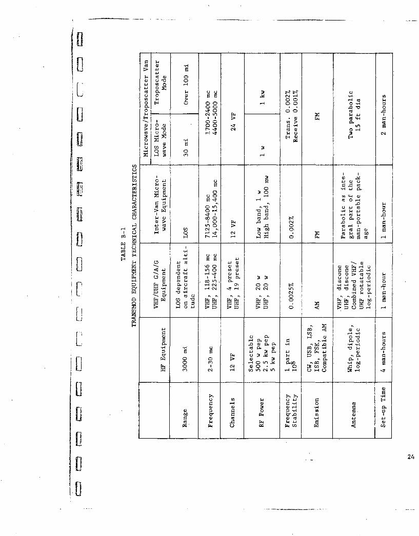
TRANSMOD equipment technical characteristics are summarized in Table B-1.
In addition, a small SSB transceiver shall be installed in all but the crypto-
graphic and utility vans.
SThe HF transmitter van shall be equipped with three transmitters that
can be operated simultaneously to provide HF circuits in three directions.
p Each transmitter shall be adjustable to select output power of 500 watts,
2.5 kw, and 5 kw peak effective power. Multiplexing and filtering devices
p shall be provided as an integral part of the transmitting equipment so that
K 22

F- 6604 570- A-IHF RECEIVER VAN HF TRANSMITTER VAN
ATENNA ACH AN
E E M IROA VE/TRANI S ATERVANI
UTILITY/TOP VANTR A
I-F
[~~F WOR *NI III__ _'
SWITCHISNG a7I FITASO OPECOFIGURE B-i
tco _ _ H_ _ _
Q~c) 0
.w- U) ~ -4
- U 0 22) . ~ C'-4 *-4 4 I'CA k z 00C- 5-4
0 E -4 0C)0 C0 .14 :0 0 *Q" 0It Cd 0 0k - C'14Lf) 44 p.4.
H-- > (U Cd4-4
H aH
o w7
H- k 3 4 C
E-4 ~ 0UW 0 -4 n -4 a)H1 4 co 0-4
w 01- Ur4- P 10,It 4C *50-44-0
0 pW (vc a 820 CLf 00
-'1 H . UU r 0 >c 4 1W C' 4-, p o . (1
H 4 ,-0 -U) ý4 C) U- 0
co a)) W' r.' -4
CO ,-4,- 44 - t )p0- ) 0 () . P. -0 0 4 -0
44 P-Pý cL-- u 00 O )4jp,OH QH PH- 0- 1 t- C4c 0(L- Ud (v "o I
PO) co 4 ='F- 6Li0 C'J -4- 01I.
U4 0) 4-4 >4 H>-4 r
u 24
[1-
the three RF circuits may be divided into 4 channels, each capable of trans-
mitting voice frequency signal s, to provide a total of 12 voice frequency
channels over the HF equipment.
The HF receiver van shall be equipped with six receivers which can be
operated simultaneously to provide diversity reception of HF signals from
I three directions. Each of the three RF signals may be divided into 4 voice
frequency channels for a total of 12 channels.
The switching and technical control van shall be equipped with a 20-U line automatic telephone switchboard, a 16-channel VFTG multiplex, red and
black teletype patch panels, VHF and UHF ground-air-ground transceivers,
and equipment to monitor and control the quality of all circuits.
The cryptographic van shall include KW-26 cryptographic equipment to
[1 provide eight, full-duplex, secure radioteletype channels.
The message center van shall include teleprinters and ancillary equip-
Liment to terminate eight full duplex secure channels, four full duplex non-
secure channels, two weather intercept channels, and other message center
Liequipment to permit message storage, manual tape relay, and tape prepara-
tion.
The microwave/troposcatter van shall be equipped with all devices
necessary to permit operation in either the LOS microwave or troposcatter
mode. Power output in the microwave mode shall be a nominal 1 watt and in
the troposcatter mode, 1 kw. The van shall be equipped with all audio and
multiplex equipment necessary to provide up to 24 voice frequency channels.
SThe utility van shall be equipped with work benches, storage facilities,
tools, test equipment, technical publications, spare parts, and all other
[ items necessary to maintain the complete TRANSMOD complex, including allL_ van-enclosed equipment and externally operated items such as antennas, power
units, air conditioners, cables, etc.
Six man-portable microwave sets shall be included to provide inter-van
communication with two spare sets. Eight man-portable multiplex sets shallfl• be furnished for operation with these microwave sets. Each multiplex set
shall provide 12 inter-van voice frequency channels, including 1 inter-vanU order wire, All of these sets will be installed in the HF transmitter van,
the HF receiver van, the switching and technical control van and the micro-
[ wave troposcatter van. Cable assemblies and all necessary connectors shall
be provided to interconnect these and other vans when the microwave is not
Sused.
25w2

In addition to the VHF and UHF G/A/G set installed in the switching
71and technical control van, racks, equipment mounts) antenna brackets, wiring,
and all other devices necessary to permit installation and operation of these
U sets shall be included as an integral part of the HF receiver van and the HF
transmitter van so that the equipment may be installed therein when desired.
[V Power for the vans will be supplied by 400 cycle, gas turbine driven units,
separate from the vans.
4.0 MODULAR CONCEPT AND CONFIGURATION
Each van with its equipment is a modular part of the complete complex
and may be deployed as necessary to meet a wide variety of contingencies.
L In turn, major items of equipment, such as HF receivers, 'HF transmitters,
VFTG, portable microwave sets, G/A/G sets, and user instruments which may
Ube transferred from one van to another, are modular parts of the van-units.
Circuit elements, such as IF strips, audio amplifiers, filters, oscillators,
converters, etc, in the form of plug-in printed circuit cards, are modular
parts of equipments and shall be mechanically and electrically compatible
with more than one item of eqdipment. The complete TRANSMOD facility shall
consist of communication elements mounted in modified S-141/G shelters that
may be assembled as necessary to meet various communication requirements.
The seven vans shall contain certain items of equipment configured and
mounted in racks that are standard for all vans, thus permitting the instal-
lation or removal of this equipment to provide the correct combination of
communication facilities.
During field operations, the HF vans may be physically separated by a
few hundred yards or even several miles in order to place the receivers in
n a low noise area and to minimize local interference and self-jamming. How-
U ever, TRANSMOD shall be designed to permit interchanging HF receiving and
transmitting equipment and VFTG equipment when it is desired to deploy a
single HF van with voice and teletype receive and transmit capability. In
addition, antenna couplers, filters and other devices necessary for duplex
U operation of HF equipment in a single van shall be provided in both the HF
transmitter and HF receiver vans. Design shall include provision for trans-
M ferring the following equipment:
1 transmitter
4 receiversI teleprinter set
1 G/A/G set4-wire subscriber instrumentsI 16-channel VFTG
U26
U

In addition to the VHF and UHF G/A/G set installed in the switching
and technical control van, racks, equipment mounts, antenna brackets, wiring,
and all other devices necessary to permit installation and operation of these
sets shall be included as an integral part of the HF receiver van and the HF
transmitter van so that the equipment may be installed therein when desired.I Power for the vans will be supplied by 400 cycle, gas turbine driven units,
separate from the vans.
4.0 MODULAR CONCEPT AND CONFIGURATION
Each van with its equipment is a modular part of the complete complex
and may be deployed as necessary to meet a wide variety of contingencies.
In turn, major items of equipment, such as HF receivers, HF transmitters,
VFTG, portable microwave sets, G/A/G sets, and user instruments which may
Ube transferred from one van to another, are modular parts of the van-units.
Circuit elements, such as IF strips, audio amplifiers, filters, oscillators,
converters, etc, in the form of plug-in printed circuit cards, are modular
parts of equipments and shall be mechanically and electrically compatible
with more than one item of eqdipment. The complete TRANSMOD facility shall
consist of communication elements mounted in modified S-141/G shelters that
may be assembled as necessary to meet various communication requirements.
IiThe seven vans shall contain certain items of equipment configured and
mounted in racks that are standard for all vans, thus permitting the instal-
lation or removal of this equipment to provide the correct combination of
communication facilities.
During field operations, the HF vans may be physically separated by a
few hundred yards or even several miles in order to place the receivers in
P a low noise area and to minimize local interference and self-jamming. How-
ever, TRANSMOD shall be designed to permit interchanging HF receiving and
transmitting equipment and VFTG equipment when it is desired to deploy a
I Iisingle HF van with voice and te~letype receive and transmit capability. In
addition, antenna couplers, filters and other devices necessary for duplex
operation of HF equipment in a single van shall be provided in both the HF
transmitter and HF receiver vans. Design shall include provision for trans-
' ferring the following equipment:
1 transmittar
4 receivers1 teleprinter setI G/A/G set4-wire subscriber instruments1 16-channel VFTG
26
This equipment shall be designed to permit transferring to and from the HF
receiver, HF transmitter, message center, and microwave/troposcatter vans.
With one transmitter removed, the HF transmitter van shall have provisions
Ufor accepting four receivers, one 16-channel VFTG, one G/A/G set, and one
teleprinter set. With four receivers removed, the HF receiver van shall
have provisions for accepting one transmitter, one 16-channel VFTG, one
L - G/A/G set, and one teleprinter set. The message center shall have pro-
vision for accepting one 16-channel VFTG, and the microwave/troposcatter
van shall have provision for accepting one 16-channel VFTG and one tele-
printer set. All except the cryptographic and utility vans shall have pro-
U vision for accepting a minimum of four, 4-wire telephone instruments and
shall have cable terminal boxes for connecting a minimum of twelve land--
Li line user circuits in addition to terminals for the interconnection of vans
via cable.
tIt is intend~ddthat equipment will be transferred from one van to
another prior to deployment; however, since the equipment may be trans-
LI ferred in the field, it shall be*designed to permit handling without special
lifting or hoisting equipment. Careful consideration must be given to thedesign, packaging, and installation of those items that are to be trans-
Iiferred from one van to another. This includes particular attention to such
items as equipment racks, mounts, wiring, cables, connectors, etc. The pre-p ferred approach is to provide pre-wired racks in the HF receiver, HF trans-
mitter, message center, and microwave/troposcatter vans.
The following are examples of possible van combinations. Two examples
are given for each configuration:
4.1 SINGLE VAN
Example 1 (Figure B-2). One HF receiver van with a transmitter,
VFTG, VHF/UHF G/A/G equipment, and one teleprinter set installed. This
U configuration provides 16 teletype and 3 voice channels, and 2 G/A/G chan-
nels.
V Example 2 (Figure B-3). One HF transmitter van with four receiv-
ers, VHF/UHF G/A/G equipment, and one teleprinter set installed. This con-
figuration provides 16 teletype and 7 voice channels, and 2 G/A/G channels.
4.2 TWO VAN CONFIGURATION
-Example I (Figure B-4). .One HF transmitter van with four HF re-
ceivBs ande --heIUHF/VHF'U G/A/G equipment ifistalled; snd one message center van
Li27

HiC -6008517-A- I
11
Ii RCVR ~~~~~~XMTRFVT ___________
3r. VOICE
LI 1VHF, IUHF 15 TTY
SMODIFIED HF RECEIVER VAN
41 FIGURE B-2
II
VFTG RCVRS XMTR XMTR
U
LTTY / @
4]r 7 VOICE -
to15 TTY I VHFI 1:UHF
fl MODIFIED HF TRANSMITTER VANFIGURE B-3
U28

riC- 68086516-A- I
RCVRS XU HILDL L•I~ 'FT 4--[- 4I-,] Il]•/•
H ~~4 TTY "''
U7 VOICE I UHF, I VHF
MESSAGE CENTER VAN' HF TRANSMITTER VAN
TWO, VAN COMPLEX
LiFIGURE 8-4
Ell
TRANSMITTINGEQUI P.
VFTS RECEIVING
II
EQUIP.
20 LINE EXPANDED
MICRO wA:VE/ TRoPo VAN.
- 1 VHF, 1 UHF 16 TTY 23 VOICE
?rECH. CONTROL V-N
[I.TWO VAN COMPLEX
29FIGUREr 8-5

1
C-680 ,514 -A-I
L,
1]MOD/FIED HF XMTR VAN pTTY .JLJ
7. VOICE
Ii 1 VHF, I UHF
il -S
'(b
Ii
CRYPTO VAN MESSAGE CENTER VAN
IlTHREE VAN COMPLEX
FIGURE B-6
STECH. CONTROL VAN' MICROWAVE/TROPO VAN
iP~u ... EUI......
, ~EQUIP. '
s o 20 VOICE
IVHF, IUHF 3 HOT LINES
MESSAGE CENTER VAN
II 12" TTY
B4 TTY
THREE. VAN COMPLEX
SFIGURE B-7 31
LI.

C-6S08512-A-I
[jMODIFIED HF XMTR VAN
wUo 7 VOICE
diii A/G
1 UHF I VHF VFTG
HD TECH CONTROL VAN
CR Ypro VAN MESSAGE CENTER VAN
B FOUR VAN COMPLEX
FIGURE B-8 32

C-666O514 -A -'I
LI HF RECEIVER VAN HF TRANSMITTER VAN
III- I I -:IL Ni-
SCRYPTO VAN MESSASE CENTER ,VAN
S~ FOUR VAN COMPLEX
SFIGURE 6-9 33

with VFTG installed. This configuration provides 16 full duplex teletype
channels, 7 voice channels, and 2 G/A/G channels.
Example 2 (Figure B-5). One microwave/troposcatter van and one
switching and technical control van.
4.3 THREE VAN CONFIGURATION
Example 1 (Figure B-6). One modified HF transmitter van, one mes-sage center van,, and one crypto van to provide encryption of eight teletype
channels.
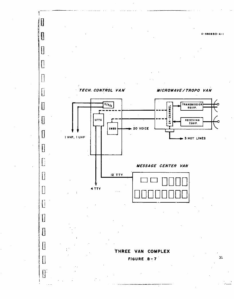
.Example 2 (Figure B-7). One microwave/troposcatter van, one
switching and technical control van, and one message center van to provide
H16 teletype circuits and 23 voice circuits via tropo or LOS microwave. Of
the 23 voice circuits, 20 may be switched and the remaining 3 may be strapped
rithrough on a hot line basis.4.4 iFOUR VAN CONFIGURATION
S~Example I (Figure B-8). One modified HF transmitter van with four
receivers installed, one switching and technical control van. one crypto-
graphic van, and one message center van to provide 16 full duplex teletypeU circuits (8 secure and 8 non-secure), 7 HF voice circuits, and 2 G/A/G
circuits.
Example 2 (Figure B-9). One HF transmitter van, one HF receiver
van with G/A/G equipment, one cryptographic van, and. one message center van
with VFTG to provide HF circuits in three directions simultaneously with a• total of 16 teletype and 11 voice circuits,, plus 2 G/A/G circuits.1 5.0 COMPATIBILITY AND STANDARDIZATION
TRANSMOD shall be designed so that mechanical, electrical, and elec-
tronic parts which have a common function are standardized to minimize logis-
tic problems and permit interchangeability. Plug-in modules shall be stand-
ardized to be electrically and mechanically interchangeable among several
items of equipment. For example, RF equipment associated with TRANSMOD
should be designed to utilize interchangeable printed circuit plug-in mod-
flules which are common to audio stages in HF, VHF, UHF, microwave and tropo-
scatter equipment. Other audio devices such as line amplifiers, monitor
amplifiers, telephone amplifiers, etc, shall also be designed to utilize
common plug-in audio stages. Low-level RF amplifiers, IF amplifiers, os-
cillators, mixers, detectors, etc, should also be standardized to the ex-Ltent practicable. Items such as cables, connectors. patch panels, perform-
ance monitors, fault indicators, alarms, protective devices, synthesizers,
etc, shall be standard throughout TRANSMOD.

Compatibility includes technical performance that assureF proper inter-
faces with fixed plant and transportable communication facilities used by
other military services. This includes DATACOM/AIRCOM stations, STARCOM/U UNICOM stations, the Naval Communications System, 412L systems, 482L systems,
U.S. and allied aircraft, military and civilian telephone exchanges, and
other equipments used by the Air Force, Army, Navy, and Marine Corps. This
specification does not include data terminal equipment to work with DATACOM
stations; however, TRANSMOD shall be provided with sufficient rack space to
permit addition of all devices necessary to insure compatibility with DATACOM
if required by the procuring activity.
The facility shall be designed to provide Voice and teletype circuits
via HF radio from a remote site to any fixed AIRCOM, STARCOM, or Naval
flCommunications System pivotal station. Teletype multiplex equipment andvoice channel multiplex equipment shall be compatible with equipment used
by those services.
Ground-air-ground VHF and UHF shall employ modulation and channeliza-
tion compatible with cargo, fighter, bomber, and fixed wing aircraft used
by U.S. and allied forces. Single sideband equipment shall be designed to
operate in the AM mode.
6.0 CHANNELIZATION
TRANSMOD shall include sufficient equipment to provide HF circuits in
i • three directions simultaneously, one microwave/troposcatter circuit, inter-
Im shelter microwave circuits, switching for local users, and trunks to remote-
ly located users. Each of the three HF circuits provides four voice frequen-
jj cy channels that may be used for voice or teletype signals. The microwave/
troposcatter van provides up to 24 voice channels, or teletype channels as
required. Ground-air-ground equipment will provide one VHF voice channel
and one UHF voice channel. In addition, transportable microwave equipment
:U for inter-van communication can be used for communicating beyond the TRANS-
MOD facility. The automatic electronic switchboard may be connected to land-
Ui lines to provide communication between TRANSMOD and nearby elements of the
operation.
Figure B-10 illustrates typical channelization between the USAF task
commander and other command elements during a limited warfare operation.
Channelization depends on operational conditions, and many combinations._• are possible.
35
Ii

C-6608461-A-
InZ00
z
w U4
< n
z U)

i 70 MAJOR COMPONENTS
[1 7.1 HF TRANSMITTER VAN
The HF transmitter van shall include three identical sets of trans-
mitting equipment, each capable of providing four 3 kc voice frequency chan-
nels. The equipment specified in the following paragraphs shall be installed
and suitably connected in this van to provide the capability specified.
7.1.1 -HF TransmittingEquipment
The HF transmitting equipment shall be modular in design
and shall employ solid state techniques throughout the audio, IF, and low
level RF stages. Maximum use shall be made of printed circuit cards which
are physically and electrically interchangeable with printed circuit cards
employed in the HF receiving equipment. Modules shall translate four voice
Lfrequencies channels into a composite IF frequency, thence into an RF signal
in the 2 to 30 mc band for amplification within the exciter. The exciter
shall furnish the drive power for the linear power amplifiers. Three power
amplifiers shall be provided, each capable of 500 watt, 2.5 kw and 5 kw
peak effective power over the range from 2 to 30 mc. The overall perform-
ance' of the HF transmitting equipment shall meet the following specifica-
tions:
a. Stability: I part in 107 after I hour warm-up and 1
part in 10 after 1 day warm-up, controlled by synthesizers tunable in 100
cycle steps.
b. -Modes of emission: CW, compatible AM, USB, LSB,.ISBSand FSK.adw c. RF channel tuning: Equal incremental steps separated
by 100 cycles over the complete band of 2 to 30 mc.
L d. Channels: Four independent voice channels such that
two 3 kc voice frequency channels are frequency multiplexed onto the upper
l sideband and the remaining two 3 kc voice frequency channels are multiplexed
onto the lower sideband to occupy a totalRF bandwidth of 12 kc. Suitable
[j devices shall be included to permit use of any one or all of these four
channels.
•I ~e. Output impedance: The transmitters shall include de-
LI vices necessary to match an unbalanced impedance of 50 ohms. Suitable
matching devices and/or antenna tuning units shall be provided to match all
HF antennas specified herein over the frequency range of from 2 to 30 mc
so that one type of coaxial cable with a nominal impedance of 50-52 ohms
37

may be used between all HF receiving and transmitting equipment and the
i specified antennas.
f. Harmonic emission: The second harmonic radiation shall
|U be at least 50 db down. Higher order harmonics shall be at least 55 db down.
g. Output distortion: Third and higher order inter-modula-
tion distortion products shall be at least 50 db down.
h. Spurious emission: All non-harmonically related spurious
output shall be at least 50 db down.
i. Carrier suppression: Carrier suppression shall be at
least 55 db.Sj. Hum and noise: Hum and unweighted noise shall be at
least 55 db below either of two equal tones when the transmitting equip-
ment is driven to maximum peak effective power ratings.
k. Automatic load and level control: Suitable circuitry
shall be included in the exciter and linear power amplifier to limit peak
power automatically and to maintain uniform power gain over the specified
frequency range.
"1. Carrier insertion: A control shall be provided to
control the amount of carrier inserted over the range of from -40 db to
full carrier.
m. Crystal filters: Four voice frequency channels shall
be multiplexed to sideband signals by means of crystal filters. The band-
pass characteristics of the filters shall be ±1 db from 350 cps to 3040 cps
with rejection of 55 db at the carrier frequency and rejection of 60 db at
6310 cps.
7.1.2 PatchPanel2A patch panel shall be furnished and installed to provide
patching for 12 voice frequency channels. This patch panel shall be between
[the multiplex equipment associated with inter-shelter ccmmunication and the
input to the radio transmitting equipment. Channels I through 12 of the mul-
IItiplex shall be patched through the panel to channels 1 through 12 of the
RF equipment. All multiplex and radio equipment inputs and outputs shall
A appear on jack strips to permit re-routing channels as desired.
7.1.3 Antenna Couplers and Filters
Antenna couplers and tuning units shall be. provided to per-
mit automatic matching to whip antennas and dipole antennas to permit.
[1 38

simultaneous operation of both transmitting and receiving equipment from
the HF transmitter van when four receivers are transferred to this van from
the HF receiver van.
7.1.4 !RF Patch Panel
An RF patch panel shall be installed to permit connecting
any of the antennas to any of the RF transmitting equipment. Four spare
ft RF connectors shall be provided.
7.1.5 VHF/UHF G!A/G.Euipment
IRack space, wiring, transmission lines, antenna feed-
through, antenna brackets, and all other devices necessary to install and
operate the VHF and UHF G/A/G equipment (paragraph 7.3) shall be installed.
7.1.6 Inter-Van Communication
i aMicrowave sets and multiplex sets (paragraph 7.8) shall beinstalled.
7.1.7 Antenna Assemblies
The following antennas and antenna supports shall be fur-
nished as part of the HF transmitter van. They shall comply with the re-quirements specified in paragraph 7.10.
3 each log periodic antennas, including supporting masts2 each fiberglass whip antennas,,each 35 ft. long2 each dipole antenna assemblies, including,4 masts, each
o 60ft. long7.2 HF RECEIVER VAN
The HF transmitter van shall include six identical sets of re-
ceiving equipment each capable of providing four voice frequency channelsin diversity. The reL&ivingequipment specified in the following para-
.graphs shall be installed in this van.
7.2.1 HF Receiving Equipment
The HF receiving equipment shall be of modular design,
using solid-.state printed circuit cards which are physically and electri-
cally interchangeable with those employed in the HF transmitting equip-
ment. The overall performance of the HF receiving equipment shall meet
the foll6wing specifications:
a. Tuning: Over the frequency range from 2 to 30 mc in
8 100 cycle increments.
b. Stability and calibration accuracy: I part in 107 af-
ter lihour warm-up, and I.part in 10 after 24 hour warm-up.
1]39

Uc. Modes: Each receiver shall be capable of operation in
SAl. A3a,.A3b, A9c, and compatible AM modes.
d. Channels: Each receiver shall be capable of receiving
3 kc voice channels contained within a 12 kc RF channel utilizing 12 A3a
emission, separating the composite signal into four 3 kc voice channels by
means of four filters, four separate IF amplifier channels, detectors, and
Usuitable-audio amplifiers.
e. Automatic frequency control: The receivers shall con-
S]tain automatic frequency control for locking onto the pilot carrier of a
relatively unstable transmitter.
f. Automatic gain control: Each receiver shall include
aditomatic gain control (AGC) circuitry automatically and independentlý'rto
control each of the four 3 kc channels. The AGC shall maintain the receiver
output within ±2 db for an input variation of 100 db with reference to I
microvolt.
g. Sensitivity: An input of 0.5 microvolt or less shall
produce a 10 db signal to noise ratio over the frequency range from 2 to 30
S!mc.h. IF rejection: IF rejection shall be 100 db or greater
Sat any operating frequency in the range from 2 to 30 mc.
i. Image rejection: Image rejection shall be greater
than 60 db over the specified tuning range.
j. Spurious response: The spurious response, other than
image, shall be no less than 80 db below the response to the desired fre-
quency over the specified tuning range.
k. Adjacent channel rejection: Adjacent channel rejection
shall be 60 db or better.
1. Radiation: Undesired radiation from the receiver over
[jthe specified tuning range shall be less than 1 microvolt as measured at
the antenna terminal.
S- m. Desensitization: With a I microvolt signal in the de-
sired channel and a signal 70 db above 1 microvolt in the adjacent channel.,
the I microvolt desired signal shall not be reduced more than 3 db.
n. Hum and noise: Hum and noise shall be at least 50 db
below the level of a received signal containing two tones of equal ampli-
tude when the receiver is adjusted to provide the rated output.
40
o. Input impedance: Receiver input circuits shall be de-
E signed for connection to 50 ohm or 70 ohm unbalanced transmission lines
with a voltage standing wave ratio no greater than two to one over the tun-
ing range.
p. Audio response: Audio response shall be ±1 db over
the range from 200 cps to 4000 cps.
7.2.2 .Patch-Panel
A patch panel shall be installed in the HF receiver van to
U provide patching for the voice frequency channels. Patching will include
facilities for 12 voice frequency channels plus an additional 3 channels
Sfor space diversity teletype reception. This patch panel shall be connec-
ted between the multiplex equipment associated with inter-shelter communi-
]cation and the radio receiving equipment.
7.2.3 RF Patch Panel
Ah RF patch paiel shall t installd in the HF receiving
van to permit connection of any of the antennas to any of the RF receiving
equipment. Four spare RF connectors shall be provided.
.7.2.4 VHF/UHF G/A/G Equipment
Rack space, wiring, transmission lines, antenna feed-
through facilities, antenna brackets and all other devices necessary to
install and operate the VHF and UHF G/A/G equipment (paragraph 7.3) shall
be installed.
7.2.5 Inter-Van Communication
Microwave sets and multiplex sets (paragraph 7.8) shall be
U installed.
7.2.6 Antenna Assemblies
SJThe following antennas and antenna supports shall be fur-
nished as part of the HF receiver van. These antenna assemblies and antenna
supports shall meet the requirements specified in paragraph 7.10.
3 each log periodic antennas, including support masts2 each fiberglass whip antennas, each 35 ft. long2 each dipole antenna assemblies, including four masts
each 60 ft. long
7.2.7 Antenna Couplers and Filters
These and other devices must be installed to permit simul-
tane6us operation of both transmitting and receiving equipment from the HF
Ii receiver van when the transmitter is transferred to this shelter from the
HF transmitter van.
ii4.1

7.3 SWITCHING AND TECHNICAL CONTROLVAN
The switching and technical control van shall be equipped with
complete switching, patching, monitoring and testing facilities for all
teletype, telephone, and radiotelephone circuits to and from the other
TRANSMOD vans and to and from users. These devices shall be designed and
installed to prevent' inadvertent cross-patching of clear classified traffic
into outgoing radio, wire, and cable circuits. In addition, sufficient
physical isolation, separation, shielding, and filtering shall be included
to prevent radiation and conduction of classified teletype data prior to
encryption. The equipment specified in the following paragraphs shall be
Iinstalled in the van.
7.3.1 20-Line Automatic Electronic PBX Switchboard
The switchboard shall be of modular construction, light-
weight, and fully transistorized. It shall be capable of switching local
and remote user circuits on a 4-wire basis to provide inter-shelter and
user communication via inter-shelter microwave and/or inter-shelter cable,
and to provide communication to external user lines. Devices shall be in-
cluded to accept calls from and to all military and commercial dial andmanual central offices. The switchboard shall be designed to switch 20
lines and 4 trunks with provision for expansion in groups of 4 lines to
handle up to 40 lines by simple insertion of plug in modules. It shall
Uprovide a cordless attendant's position to assist users. Conference serv-
Sice shall be provided to connect all seven vans plus an outside call by
dialing the van extensions in a prescribed sequence without assistance from
the attendant. Wall mounted and field type 4-wire telephone sets shall be
provided in each shelter to operate in conjunction with this switchboard.
These instruments shall be equipped with digit keys ifi lieu of the conven-
tional dial for signaling.
S7.3.2 Voice Frequency Telegraph Terminal (VFTG)
One transistorized 16 channel VFTG terminal shall be in-
U stalled in the switching and technical control van. This unit shall be de-
signed to permit patching any combination of the teletype receive and trans-
mit channels to the three HF circuits and the microwave/troposcatter cir-
cuits for simultaneous transmission and/or reception of teletype to and fromuseveral directions. The VFTG equipment shall be capable" of space
42

I
diversity.and frequency diversity reception with signaling speeds of 100
wpm. The channels shall employ standard frequency assignments from 425
to 2975 cps, spaced at 170 cps, and employ frequency shift capability of
U±42.5 and ±425 cps.
This VFTG shall be compatible with the following equip-
ments: AN/FCC-7, -8; AN/FGC-29, -60, -61, -61A; AN/TCC-30; and AN/UCC-l.
Design shall include all ancillary equipment in a single standard 19'inch
rack, and total weight shall not exceed 300 pounds. The frequency stability
of the output signal from each channel shall be ±0.5 cps. Back-to-back dis-
tortion at 75 bauds shall not exceed 5% on channel 1 and shall not exceed
i 3% on all other channels. The DC input and output circuits of the VFTG
receiving and transmitting units shall be capable of operating with polar
Sor neutral keying, at the user's option, on signal loops from 20 ma to 100
ma with voltages as high as 150 volts.
7.3.3 Patch Panels
"Red1" and "black," and audio patch panels shall be in-
stalled in the switching and quality control shelter to permit complete
Iicross-patching and testing of equipment. The red will be used for patching
of all clear, classified teletype signals; the black patch will be used forUpatching all encrypted classified teletype signals, and unclassified signals.
The audio patch panel will be used to patch all voice frequency teletype
tones to the multiplex equipment for transmission via microwave or inter-van
cable to and from the HF vans and the microwave/troposcatter vans. The red
jacks and associated red patch cords shall be sufficiently different from
U all others utilized in TRANSMOD to prevent inadvertent cross-patching of
1i clear classified traffic into the system radio and wire lines.
_ 7.3.4 VHF/UHF G/A/G Transceivers
Two transceivers shall be installed in the switching and
0 technical control van to provide VHF and UHF G/A/G radio communication.
These units shall be completely transistorized in the low-level RF states
H and shall employ interchangeable printed circuit cards. Each of the units
shall employ amplitude modulation and shall occupy no more than 18 inches
of the standard 19 inch rack space, including power supplies and control
units. Each transceiver unit shall weigh no more than 30 pounds.
The VHF transceiver shall operate in the frequency band
of 118 to 156 mc with a power output of 20 watts, and the UHF transceiver
shall operate in the frequency band of 225 to 400 mc with a power output
B of 20 watts. It shall be possible to operate both units simultaneously.Soperat

Both units shall operate from 115 volt) 3 phase, 400 cycle power. Both
units shall be automatically tuned, and frequency selection shall be accom-
plished by a control unit located in the rack with the transceivers. The
VHF unit control shall provide selection of four preset channels and se-
lection of all channels in the band 118 to 156 mc, and the UHF unit control
shall provide selection of 19 preset channels with manual selection of thet ffull complement of 3500 channels each separated 50 kc. These units shall
be equipped with voice operated relays to permit two-way operation through
the 4 wire switchboard from remote user instruments. All devices shall be
installed to permit operation of this equipment from local or remote posi-
Stions. Rack space, wiring, antenna brackets, etc, shall be provided to
permit installing the VHF/UHF G/A/G sets in the HF transmitter, HF receiver,
and microwave/troposcatter vans when required. Frequency stability shall
be 25 parts in 106 (0.0025%) or better for both VHF and UHF G/A/G equipment.
- 7.3.5 Inter-Van Communications
Three 12 channel multiplex units and three man-portable
microwave sets shall be installed in the switching and quality control van.
S ]In addition, rack space, wiring, brackets, cable enlrance "facilitie f
and all other devices necessary to permit installation of one additional 12
channel multiplex set shall be provided to permit expansion when it is de-
sired to relay the 24 voice frequency channels from the microwave/tropo-
f • scatter van through the switching and technical van for distribution.UJ 7.4 CRYPTOGRAPHIC VAN
ri The cryptographic van shall be equipped with eight TSEC/KW-26
Fl on-lifie synchronous cryptographic sets. to provide full duplex operation
for eight secure channels. In addition, the following equipment shall be
installed in the shelter:
a. Two central distribution frames (CDF), one for red lines andLone for black lines. All red and black circuit connections, patch panels,
cables, connectors, CDF's cables, and other devices shall be installed in
accordance with existing security regulations and specifications.b. One teletype set for test purposes.
c. Patch panels wired: to permit connection to the input and out-
I put of TSEC/KW-26 equipment for test purposes.
d. A master level-set chronometer.
44

e. File cabinets and/or safes as required by existing security
regulations.
f. Work benches, desks, and storage cabinets as space permits.
g. Grypto destruction kit.
7.5 MESSAGE CENTER VAN
The message center van shall be equipped with all devices neces-
sary to provide normal message center operational facilities and teletype
equipment to terminate eight full-duplex secure teletype channels, four
full-duplex non-secure teletype channels, and two weather monitor (receive
only) machines. The equipment specified in the following paragraphs shall
[Ibe installed in this van to provide the capability specified.
7.5.1 Teletype Receiving Equipment
Eight teleprinter sets, without keyboards, shall be in-
stalled to terminate the receive side of the eight secure teletype dircuits;.
These machines shall be suitably wired through red central distribution
frames and red patch panels to the output side of the TSEC/KW-26 receivers
located in the cryptographic van. Eight printing reperforators shall beU connected to the receive side of these circuits to provide a punched tape
in addition to the page copy contained from the page printer. Four tele-
printer sets, without keyboards, shall be wired through black CDF's to the
black patch panel to terminate non-secure circuits. Four reperforators
P[ shall be connected to these four circuits to provide a punched tape of all
I Limessages received. These reperforators shall be wired so that they can be
disconnected. Two teleprinter sets, without keyboards, shall be installed
to monitor weather information.
7.5.2 Teletype Transmitting Equipment
Twelve teleprinter sets shall be installed on the transmit-
ting side of the 12 full-duplex teletype circuits (8 secure, 4 non-secure).
Each machine shall include a keyboard transmitter-perforator, page printer,
printing reperforator, and tape reader-transmitter contained in a single
package, physically independent of one another except for a common drive
motor for the printing reperforator, keyboard, and tape reader-transmitter.
7.5.3 Ancillary Equipment
8 All equipment necessary for normal message center operation
shall be installed in space available within the message center, This shall
include items such as a clock, safe, filing cabinets, typewriter, desk, etc.
1145ip

7.6 MICROWAVE/TROPOSCATTER VAN
FThe microwave/troposcatter van shall be designed for primary use
as a 1 kw troposcatter unit for operation over paths of 100 miles or more.
[I It shall include an exciter with a minimum RF output of 1 watt that can be
used as a LOS microwave transmitter over nominal path lengths of 30 miles.
It shall operate in the dual diversity mode in the 1700 to 2400 and 4400
to 5000 mc frequency ranges and shall provide 24 voice frequency channels
plus an order wire.
Voice frequency multiplex equipment shall be installed to separate
the combined baseband signal into individual voice frequency channels for
Iidistribution directly from this van to telephone user dropouts. Provision
shall also be made to permit connection to the inter-van microwave system at
Hbaseband for relay to the switching and technical control van. A pre-wired
rack and all other devices necessary for connection and operation of the VFTG
specified in paragraph 7.3.2 shall be installed in this van to provide full
teletype service when the switching and technical control van is not deployed.
With the VFTG multiplex installed in this van, it shall be possible to route
channels through the inter-van microwave equipment at baseband while at the
same time dropping out voice and teletype circuits for direct user service
U from the microwave/troposcatter van.
Patching and switching facilities shall be furnished to provide
any combination of dropout circuits. The necessary elements of the set
shall include devices and circuitry to provide automatic bandwidth control
for improved threshold margin when receiving weak signals. Transmitting
and receiving equipments shall be designed as broadband units and shall be
equipped with plug-in passive filter modules to provide variable bandwidth
C; iin RF and IF stages. Means shall also be provided to bypass the filters
when they are in place and broadband operation is desired. Frequency syn-
thesizers shall be employed to control the frequency of transmitting and
receiving equipment. These synthesizers and other frequency control de-
U vices shall have the degree of stability necessary to provide an overall
stability of 0.002% in the transmitting elements and 0.001% in the re-
ceiving equipment.
7.6.1 Transmitting.Equipment
The transmitting. equipment shall include an exciter and
power amplifier meeting the following specifications:
B 46

a. Exciter: Emission shall be F9 with a power output of
1 watt or more sufficient to drive a 1 kw power amplifier. All devices shall
be furnished and installed to permit bypassing the I kw 'amplifier and feed-
Li ing the antenna directly for LOS microwave operation.
b. Power amplifier: The power amplifier shall amplify
the modulated output of the exciter to the desired power level of 1 kw.
The complete power amplifier, including all control circuitry, power supply
klystron, and RF plumbingshall occupy no more than 4 feet of rack space.
7.6.2 Receiving Equipment
Receiving equipment shall include duplexers, combiners,
Liand all other devices necessary to provide dual diversity operation. It
shall meet the following specifications:
a. Bandwidth control: The receiving equipment shall be
designed to provide automatic bandwidth control that will automatically
decrease the bandwidth of the receiver as the input signal strength ap-
proaches the level that would normally be the threshold for the receiver.
The automatic reduction in bandwidth shall lower or extend the receiver
I Uthreshold at least 6 db, thereby increasing the fade margin and making it
possible to utilize weaker signals.
b. Noise figure: The receiving equipment shall be
equipped with a parametric amplifier to provide an overall receiver noise
figure not greater than 4 db.
7.6.3 -Antenna Assembly
The antenna assembly shall be 15 feet in diameter. It
shall have a gain of at least 41 db (over isotropic) for all frequencies
within the 1700 to 2400 and 4400 to 5000 mc ranges. The antenna assembly
shall be either the ring mounted inflatable type or the sectionalized
metal type and shall be constructed of lightweight, high strength, durable
{jI materials. It shall be designed to withstand repeated and strenuous usage
under the service conditions specified herein. If inflatable antennas are
U furnished, suitable air compressors shall be properly connected to maintain
proper inflation of the antennas. The contour of the parabolic reflecting
surface shall be capable of being maintained within ±1/16 wavelength at
5000 mc. The antenna shall be held up-by a mechanism consisting of tele-uscopic vertical and horizontal outrigger members designed to support it
47

-.... ...-. .-- - -
In high-velocity winds. All devices required for erection and orientation
shall be included. Additional technical characteristics are:
a. Beamwidth: Beamwidth as measured between half powerfj - points shall not exceed 1.1' in either the E or H plane of polarization for
any operating frequency within the range specified. Side lobes within 90'p of the main lobe shall be down at least 16 db, and lobes in excess of 90*
shall be down at least 28 db.
b. Polarization isolation: At least 30 db.
c. Weight: Each antenna assembly, including the antenna,
antenna support, and all installation hardware, shall be stowable in the van
-. during transit, shall be packaged in a transit case or skeletonframework
suitable for lifting by helicopter and shall weigh no more thanlI000 pounds.
d. Antenna feed: Bi-polarized feedhorn.
e. Az-El adjustment: All devices shall be provided to per-
mit azimuth adjustment of at least ±15' from center position and elevation
adjustment of at least -5* and +10'.
7.6.4 Ancillary-Equipment
Thi' microwave/troposcatter van shall include a duplexer
to permit simultaneous transmission and reception by means of a common an-,
tenna feedhorn, fault indicators, performance monitors, alarms, dummy loads,
and amplifiers to control the levels at baseband and voice frequency. The
van shall also include a pre-wired rack with all devices necessary to per-
mit the installation of an AN/TGC-15 teleprinter for monitoring teletype
U channels when the VFTG multiplex equipment is installed, and a pre-wired
rack for the installation of VFTG multiplex equipment.
7.7 UTILITY VAN
ti The utility van shall furnish storage space for spare parts, and
shall include maintenance equipment and work space for maintenance person-(Anel. It shall include built-in and portable test equipment. The utility van
shall -Vie capable of being transported to permit maintenance visits to other
U shelters on a scheduled or emergency basis. Since it may be moved frequent-
ly, it must be capable of withstanding severe shock and vibration.ft Wherever possible, electronic, electrical, and mechanical com-
ponents shall be capable of being transported when mounted in normal opera-
ting position. Small items which are not mounted shall be stored in com-
partments designed to protect them while in transit. Storage compartments
[1.48

for delicate instruments shall be padded drawers designed to fit each item
of equipment and its accessories. Labels shall be attached to identify each
drawer. Compartments shall be equipped with latches that prevent them fromV• accidentally opening when the van is in transit. All other items shall be
equipped with devices to fasten them quickly in place and prevent them from
moving about while the van is in transit. No special tools shall be re-
quired to prepare for the transit condition.
Spare parts shall be included for all communication-electronics
Uequipment, antennas, engine-generator sets, and air conditioning sets in
sufficient quantities to permit operation of TRANSMOD for a period of at
least 30 days with no outside supply of maintenance parts. A system shall
be provided to permit rapid location of spare parts and provide a means of
controlling stock levels. This shall include labels, locator cards, cross-
reference, and other aids necessary. The items to be provided shall consist
of but are not limited to the following:
Work benches with visesElectronic equipment repair kitTeletype repair kitElectronic test equipment (both portable and mounted)Racks, shelves, cabinets, drawers, bins, etc, for the storage of
portable test equipment, spare modules, tools, etc.Technical publicationsPortable battery chargersPortable engine-generatorsAntenna sparesAntenna repair kitsEmergency lighting devices and trouble lightsMaintenance expendables such as wire, tape, solder, hardwarePower toolsBin6culars for antenna inspectionFire extinguishersVacuum cleaner for cleaning electronic equipment
7.8 INTER-VAN COMMUNICATION
B Multi-channel traffic and order wire communication between van '
shall be provided by a lightweight, portable microwave and multiplex package
S1similar to the AN/TRC-56 or AN/TRC-92. The design of the inter-van microwave
transmitter-receiver set and multiplex shall be such that the equipment may
be mounted in racks in the vans or in weatherproof carrying cases for opera-
tion outside the vans. The multiplex set shall be completely solid-state.
The microwave set shall be solid-state with the exception of the transmitter
B klystron and receiver local oscillator klystron.
49
iiI __ _

The microwave carrying case shall be in two sections so that the
antenna may be separated from the set and placed outside the van while the
rest of the equipment is inside the van. It shall also be possible to com-bine the receiver-transmitter and antenna cases to form a single, weather-
proof microwave unit,. The antenna assembly shall include an all-weather
radome. Optical sighting devices shall be included as part of the assembly
to assist in orienting the antenna. The entire microwave assembly shall be
P] equipped with a tripod support assembly that may be attached to the carrying
•J case for positioning the set on the van roof.
Frequency modulation shall be empl6ygd, and the power output shallSbe at least 1 watt in the 7125 to 8400 mc band. The RF bandwidth shall be
adequate to pass twelve 4 kc voice channels, data channels, and an order
Iiwire. The order wire channel shall have in-band signaling which can be
operated from the multiplex package. The order wire shall be used for inter-
ijcommunication between TRANSMOD vans.
Frequency division multiplex sets shall be provided to work in
conjunction with the inter-van microwave sets to multiplex voice, teletype,
and data channels. This unit shall be fully transistorized, shall weigh no
more than 100 pounds, and shall provide twelve 4 kc voice frequency channels
U plus the capability of providing 1200 bps data channels. Modulationharmonic
distortion, phase distortion, frequency response, and other technical charac-
teristics shall meet CCITT standards. The switching and technical control
van shall be equipped with three microwave sets and four 12 channel multi-
plex sets; the microwave/troposcatter van shall be equipped with one micro-
wave set and two 12 channel multiplex sets. The HF transmitter van and HF
f I receiver van shall each be equipped with one microwave set and one multiplex
set. Spare microwave and multiplex sets shall be furnished as specified by
the procuring agency to provide communication between TRANS1OD and other
elements involved in a limited warfare operation.
7.9 GAS TURBINE-GENERATOR SETS
The primary power source for TRANSMOD shall be a 20 kw, 400 cps,
gas turbine driven generator set that, when used singly or in combinations
B two or more, shall satisfy the input power needs of each TRANSMOD van. The
generator set shall be self-contained and shall include a gas turbine prime
mover with controls, a brushless generator with regulator, an instrument and
control panel, a line conta-c,tbr and controls, a 28 VDC battery, a fuel tank,,
LIa fuel pump and controls, and a unit enclosure. The general requirements are;
50

a. Rating: The set shall be rated at 20 kw, 1.0 to 0.8 power
factor (lagging), 3 phase, 4 wire, 120/208 volts, grounded neuitral, 400 cps
constant frequency AC when subjected to the environmental conditions speci-
fied herein.
b. Weight and. volume: The set shall be lightweight and as compact
as possible with maximum total limits of 400 pounds and 24 cubic feet respec-[i tively.
c. Initial activiation at site: The set shall be designed to per-
(3 mit setting up, starting, and assuming rated load within I hour following de-
ployment to any communication site under the environmental conditions herein-
after defined.
d. Maintenance and servicing: The set must be able to operate
continuously for a minimum -of"72 hours between routine maintenance shut-
downs, and shall have a minimum service use of 1500 hours between overhauls,
when provided with routinr maintenance as prescribed by the manufacturer.
The set shall be designed to be serviced with standard tools.
e. Environmental limits: The set shall be capable of being
started at altitudes from sea level to 15,000 feet. Rated performance
should be attainable at 10,000 feet qith an ambient temperature of 95' F.
The set shall start and operate satisfactorily at ambient temperatures from
-65 0 F to +125 0 F. The set should be designed to meet essentially all the
U cold, weather and desert-tropical operating conditions defined in MIL-E-
4158B and MIL-E-4970A. In addition to the ambient temperature extremes,
these conditions shall include exposure to salt atmosphere, sand and dust,
insects, fungi, wind, ice, fog, mildewand rainfall that can be encountered
in the worldwidde environment.
f. -Starting gystem: The set shall be equipped with a DC starter
motor. The starter assembly shall include a clutch and a motor relay which
Lwill disconnect the motor from the turbine and DC power source, respectively,
upon completion of the starting cycle. The set shall be capable of starting
U at -65°F with a 28 volt heavy duty nickel cadmium battery to be furnished
with each set. The starting system shall be suitable for complete auto-
matic starting at all ambient temperatures between -20*F and +125*F. In
addition, all devices necessary to permit :manial'. starting shall be pro-
vided.
(3 7.10 ANTENNA ASSEMBLIES
-The following antenna assemblies in the quantities specified here-
Uin shall be furnished as part of TRANSHOD. (Other antenna assemblies are
5i

described in paragraph 7.6.3.) All' assemblies shall be complete with neces-
sary guying kits and erecting kits and shall include erecting devices such
as winches, special tools, mounts, anchors, and insulators. Structural
fuses shall be employed on log periodic and dipole antennas to prevent seri-
ous damage when the antennas are subjected to high winds. Captive hardware,
F1 captive tools, and color coding of elements shall be employed to simplify
assembly of all antennas.
All HF transmission lines furnished with TRANSMOD shall be
the coaxil type with a nominal'impedance of 50-52 ohms. Only one type of
cable shall be furnished for all HF antennas. Matching devices will be -fur-
nished as necessary to assure proper termination of all transmission lines.
Supports for bbth'the log periodic and dipole antennas
•I shall be capable of withstanding vertical and horizontal loads as may be en-
countered when supporting log periodic antennas and be of sufficient height
to assure proper performance of the antennas specified herein. These units
shall be erectable by mechanical means to a minimum height of 60 feet. All
devices necessary for erection of the masts shall be included. Non-metallic
Iiantenna guys and supports shall be synthetic fiber rope.
7.10.1 Log Periodic Antenna
The log periodic antenna furnished as part of TRANSMOD
shall meet the following requirements:
a. Weight: The maximum weight of the complete log peri-
odic assembly, including all hardware, support mast, balun, and transit
case but excluding coaxial transmission lines, shall not exceed 250 pounds.
b. Maximum stowed volume: The stowed volume of the com-
plete assembly shall not exceed 50 cubic feet.
c. Maximum stowed length: The maximum stowed length shall
not -exceed 12 feet.
Ld. Erection time: The antenna shall be designed so that
two men can erect the entire assembly in 2 hours or less.
Ue. Environment: The antenna shall be capable of with-
standing winds of 100 mph with no ice, and winds of 50 mph with 1/2 inch of
11radial ice. The assembly shall include replaceable structural fuses whichwill fail when these limits are exceeded.
Sf. Frequency: 4 to 30 mc!ILA g. Gain: The gain shall be between 10 db and 13 db rela-
tive to an isotropic antenna over the specified frequency range.
52

h. Input impedance: A balun shall be provided as part
of the antenna assembly to match a 50 ohm coaxial transmission line.
i.. Power handling capability: 5 kw peak effective power.
j. VSWR: The VSWR shall not exceed 2.1 over the speci-
fied frequency range.
U k. Azimuth beam pattern: The nominal azimuth beamwidth
shall not exceed 800.
1. Elevation plane pattern: The elevation plane pattern
shall provide high take-off angles of approximately 700 at 4 mc and lower
take-off angles of approximately 100 at 30 mc.
4J m. Polarization: Horizontal.
n. The log periodic antenna shall be designed so that the
2 to 4 mc dipole antenna and filter network specified in paragraph 7.10.2 may
be mounted on the mainmast and arranged to be fed either from a separate RF
L transmission line or by a common transmission line.
7.10.2 Dipole Antennas
Adjustable dipole antennas shall be provided as part of
TRANSMOD. Adjustments shall include the capability of providing resonant
half-wave antennas over the range of 2 to 30 mc. The design shall include a
Lmethod of easily adjusting the antennas to proper length without actually
cutting the elements. Jumpers may be used only at the ends of the elements.
It shall be possible to lower the antenna to the ground without lowering
the antenna supports,, Minor adjustments of element length shall be possible
[Iwhile the antenna is erected.
In addition, a simple dipole antenna assembly, adjust-
able to resonance over the frequency range from 2 to 4 mc, shall be in-
cluded as part of the log periodic antenna assembly. This dipole antenna
shall be supported at the center by the log periodic mast. It shall in-
clude a frequency-sensitive RF filter device that will present a low im-
pedance to frequencies below 4 mc and a high impedance to frequencies above
Li 4 mc so that it can be used in conjunction with the log periodic antenna
and fed by the same RF transmission line. With this antenna, the frequency
range of the entire assembly is extended downward to cover the 2 to 4 mc
range, with a correspondingly higher take-off angle for shorter hops. It
shall also be possible to disconnect this dipole and filter combination
U from the log periodic transmission line and feed it with a separate
53

transmission line from a second transmitter, thus providing two antennas
Swith a single main support. This combination may be used to provide anten-
nas for short hop and long hop HF transmission paths without deploying theI• 2 to 30 mc dipole antenna.
7.10.3 Vertical Whip Antennas
Vertical whip antennas furnished as part of TRANSMOD shall
be 32 feet in length and shall be constructed of fiberglass in light sections.
They shall include tuning units to match the antenna to a nominal impedance
of 50 ohms over the frequency range of 2 to 30 mc. The antenna base insulator
and mounting shall be included as part of the HF transmitting van and HF re-
ceiving van.
7.10.4 VHF-UHF G/A/G Antennas
Fl One VHF discone antenna and one UHF discone antenna shall
be provided with TRANSHOD to provide G/A/G communication. These assemblies
shall include all masts, mounting hardware, and transmission lines. TheL mounting assemblies shall be compatible with the mounting facilities pro-
vided on the HF transmitter, HF receiver, switching and technical control,
and microwave/troposcatter vans. In addition, two identical log periodic
antennas shall be provided. These antennas shall be designed to operate
SIover the frequency range of 118 to 400 mc. These assemblies shall include
all masts, mounting hardware, and transmission lines compatible with the
mounting facilities on the vans that accommodate them. In addition, de-
vices shall be provided to permit polarizing the antennas in the vertical
and horizontal planes without lowering the antennas. These mechanisms'shall
be hand-operated with positive locking devices that may be operated from
the ground.
L 7.11 AIR CONDITIONING, HEATING, AND HUMIDITY CONTROL
In keeping with the moddlar concept, the air conditioning equip-
Iiment shall be in standardized units which may be used singly or in multiples,
depending upon the cooling/heating capacity desired. The unit shall be of
Sthe all-weather, vapor-cycle, electric powered type and should have a nom-
inal cooling capacity of 36,000 BTU/hr (3 tons) at an ambient dry bulb tem-
flperature of 125*F. and a recirculated air inlet temperature of IO00 F. In
addition, the unit shall have a heating capacity of 20,000 BTU/hr at anSadibient dry bulb temperature of -65°F. The units shall be designed to per-
mit connection to the vans in parallel; however, they shall also be capable
54

of being connected in cascade,, with the output of one unit connected to the
input of the other. The folllowing specifications apply:
a. Operating life: The unit shall be capable of operating for
V 5000 hours without major overhaul. It shall be capable of such operation
after a storage of up to 2 years.
F pb. Reliability: The mean time between failures should not be
Lless than 320 hours of unit operation.
c. Electrical: The air conditioner shall operate from 3 phase,11 4 wire, 120/208 volt, 400 cps alternating current power sources. The max-
imum power requirement shall be 8.5 kw with a power factor of 0.80.
d. Size: The volume of the air conditioner shall be 18 cubic
feet or less and shall be designed to be transported in the aisles of the
FTRANSMOD vans. It shall weigh no more than 300 pounds. The unit shall
be fully enclosed in a rigid, lightweight metal enclosure, insulated to
Li prevent heat loss and sweating. The case and all openings shall be weather
tight to preclude the entrance of wind dtiven rain, dust. and snow. The
doors, latches, handles, and -covers shall be hinged and when in the non-
operational condition shall be maintained in a flush position. The cabinet
shall be so made as to provide easy access to all the components of the re-
frigeration, fan, power, and control systems. The cabinet should be so con-
structed- that the units can be stored one unit upon another.
fl7.12 USER INSTRUMENTS
Four-wire telephone sets utilizing tone keying and tone ringing
U shall be provided to terminate telephone and radiotelephone channels. Desk
sets and/or wall-mounted sets and field sets shall be provided. They shall
be basically the same electrically. They shall be equipped with a tone
signaling keyset, receiver volume control, tone-ringer volume control, a
r receptacle for connecting a headset, and a headset in-out switch. They
shall be equipped with both a handset and headset. A keyset with 12 keys
shall be used instead of the conventional dial. Keys shall be 1 through 0
jJ for priority calls, and C for conference calls. The desk sets shall operate
on a common battery basis from the van-enclosed DC power sources, and theffield sets shall operate on a local battery basis or on a common battery
basis from the van-enclosed DC power source.
Both sets shall be designed so that two sets can be connected in-
dependently of the switchboard for communication between the van interior
I and exterior for maintenance, antenna alignment,. etc. In this case,
55

signaling will be accomplished by lifting the handset and depressing any
key on the keyset. Each of the seven TRANSMOD shelters shall be equipped
with a wall-mounted telephone set. This set shall include an operators
handset with single receiver, a boom-mounted microphone, and a coil cord
'J of sufficient length to permit the operator to observe and adjust all equip-
ment in the shelter while wearing the headset when the headset is connect4ed
to the wall-mounted telephone set. In addition, a field set shall be pro-
vided with each of the seven shelters. A total of 10 spare sets (5 field[1 sets and 5 desk sets) shall be provided. In addition, desk sets shall be
provided and installed in the crypto and message center van-'.
7.13 TECHNICAL CONTROL AND TEST EQUIPMENT"All equipment necessary for monitoring, testing, analyzing, caili-
brating, aligning, adjusting, implementing, operating, and maintaining
TRANSMOD shall be included to control the technical quality and levels of
circuits, channels, and individual equipments. This shall include built- in
and patchable performance monitors, built-in fault indicators, and portabae
test equipment. Most of the latter will normally be located in the utility
[van; however, this does not preclude the use of portable test equipment ixn
other vans. Meters shall be installed to monitor the operation of DC tel4-
type loops, battery charges, emergency batteries, primary power inputsR.F
inputs and outputs, audio levels, etc. Devices such as amplifiers, distor-
tion analyzers, equalizers, etc, shall be provided to control the quality
and levels of critical incoming and outgoing channels. Teletype distortidon
measuring equipment and devices for regenerating and correcting such dis-
tortion shall be supplied: Equipment for analyzing, adjusting, monitorixig
and trouble-shooting single sideband signals shall also be included.
[ Self-checking devices and diagnostic devices shall be provided
as an integral part of communication equipment to indicate equipment faillure
U or degradation in performance. Maximum use shall be made of built-in test
equipment, and meters shall be included in circuits requiring voltage, cu:r-
rent, or power changes and adjustments and in circuits that may change in
performance during normal operation. All equipment adjustments shall be
located to permit the operator to read the associated meter while making
adjustments, and all meters shall be visible from the front of equipment.
If several voltages can be displayed in turn on a single meter, multi-
Sposition and ganged switches shall be used where one meter can be applied
to several test points. These multi-position switches shall be clearly
13 56
13

marked to identify the circuits to which the meter is connected and the sig-
nificant electrical quantity being measured. Maximum use shall be made ofI•. automatic test devices and go-no-go devices to permit rapid analysis under
field conditions. Meters and associated switching or patching devices shall
be provided to permit connection to all external telephone lines and internal
audio circuits to measure levels.
7.'13.1 Technical Control Equipment
The major items of technical control equipment to be in-
stalled in the switching and technical control van are those associated with
the quality control of teletype signals and audio signals. This equipment
,Ii shall include but is not limited to the following:
a. Direct current milliammeters calibrated in 100-0-100
(1I milliamperes to monitor teletype loop current.b. A digital distortion analyzer to provide comprehensive
distortion analysis of all synchronous and stop-start signals with readings
displayed on a front-panel meter to indicate percentage of distortion.
c. A test pattern distortion generator which will transmit
test patterns with distortion varying upward from zero in steps of 1% to
approximately 50%.
d. A time base generator to provide timing signals at the
desired baud rate for the distortion analyzer and test pattern distortion
analyzer. Baud rates normally encountered shall be provided by means of
plug-in printed circuit cards, with the desired baud rate selectable at
El the operator's option by a panel-mounted switch.
e. A 5 inch cathode ray oscilloscope with associated cir-
cuitry to permit analyzing the waveshape of single teletype characters.
[3 f. An audio distortion measuring set to measure levels,
distortion, hum., and noise on incoming and outgoing audio circuits. This
[3set shall have the following technical characteristics: distortion measure-
ments from 50 to 18,000 cps; noise and hum measurement from[30 to 45,000 cps;
[1distortion range from 0.1% to 30%; noise range from -80 db; power level
range from -60 dbm to +20 dbm; input impedances a0d000 ohms and u00,000 ohms.
g g. A transistorized audio oscillator for the testing andalignment Of channels. This item shall have an audio output of up to I
watt over the frequency range from 20 to 200,000 cps, with a maximum dis-
tortion of 1% at an output of I watt, and a response of ±1 db over the fre-
quencyrange.U 57

h. A frequency counter with a display consisting of eight
non-blinking rectangular indicating tubes in line for an eight digit display.
The counter shall be designed with completely solid state components and
shall be rack mounted. It shall measure frequencies up to 30 mc and have a
stability of not less than ±3 parts in 10 per day or better.
i. A rack-mounted oscilloscope for analyzing waveforms.
j. All devices necessary to analyze and adjust levels of
all audio circuits entering and leaving the switching and technical control
[•j van.
7.13.2 HF Radio Test Equipment
The major items of test equipment to be installed in the HF
transmitter and HF receiver Vans are those associated with frequency measur-
ing, testing as single sideband signals, and measuring and controlling of in-
coming and outgoing audio signals. Both shelters shall be equipped with a
frequency counter and devices necessary to analyze and adjust the levels of
all audio channels entering and leaving the vans. The HF transmitting van
shall include a single sideband spectrum analyzer with cathode ray tube
IU display, an integral two-tone audio generator, and an RF tuning head to meas-
ure transmission bandwidth, residual hum, carrier amplitude, harmonics, dis-
fltortion, and other characteristics of the HF transmitter.
7.14 VANS
All vans shall be the S-141/G type conforming to MIL-S-52059,
with the exception that the overall external length shall be increased to
156 inches (13 feet). Each van shall be equipped with a lightweight re-
tractable or removable wheeled undercarriage. Each van, with its specified
load and with wheels removed or retracted, shall be designed to permit load-
ing on the beds of standard military vehicles for cross-country mobility,
shall be capable of type III mobility when towed with the wheeled undercar-
U riage in place and/or extended, and shall be equipped with lifting and tie-
down eyes to permit transport by cargo aircraft and helicopter.
The vans shall include all mounting brackets, entrance ports,
connectors, ducts, panels, and other hardware to:
Interconnect vans by means of multi-conductor cableMount VHF and UHF G/A/G antenna supportsMount the inter-van microwave package and/or antenna assembly
Connect the output from the gas turbine 400 cycle generator
58

Accept the flexible air conditioning ductsProvide feed-through for RF transmission lines to and from an-
tennas.Provide distribution of conditioned airProvide lightingProvide power outlets and a power distribution panelProvide cable entrance
[2 Weatherproof corridors shall be provided to interconnect the
switching and technical control van, the message center van, and the crypto-
graphic van in an "inverted T" configuration. Since the doors of these
vans shall face the corridorl, it will be necessary to provide a door in
the corridor assembly and a set of access stairs. The corridor shall be
V3 constructed of lightweight, durable material; shall be collapsible to oc-
cupy the minimum possible space when stowed in the transit condition; an,'
fi shall include all hardware and instructions for unpacking, assembly, in-
stallation, disassembly, and packing. No special tools shall be required
Li• to perform these operations, and maximum possible use shall be made of
captive hardware.
8.0 IMPLEMENTATION
TRANSMOD shall be designed to minimize the time required'for implemen-
tation or set-up of each van. The design shall be such that no more than
24Q man ,.hours- will be required to set up the seven vans. The major por-
tion of set-up time will be expended in erecting and orienting antennas;
[ therefore, design of TRANSMOD shall include devices that reduce this time
to the absolute minimum. The following should be considered in the design
[1of antenna. assemblies and supports:a. Design to include the minimum of critical assembly and installation,
steps.
b. Include captive hardware.
c. Include plastic, weather-proof instruction plates.
Ui d. Design transit packaging so that equipment is stowed and removed
in proper sequence for assembly and: disassembly.
Sle. Color-code and number component parts of antennas and antenna
supports to facilitate identification and to indicate assembly sequence
U and/or location.
f. Provide a. transit, compass, and other devices necessary to orient
p antennas.
L59

g. Make antenna supports simple to erect, operate, and maintain and
able to withstand rough field handling. Telescopic elements are not recom-
mended unless they can function properly when dented and when covered with
V •dirt, sand, ice, and mud. Manual erection with the use of cables, pulleys,,
hoists, or winches is recommended rather than hydraulicof pneumatic erection.
h. Provide means for adjusting microwave and troposcatter antennas in
azimuth and elevation with the antennas installed. Azimuth and elevation
angle indicators calibrated in 0.50 graduations shall be attached to antenna
ti assemblies and shall be closely readable with the naked eye. In addition,
leveling indicators and telescopes shall be included to provide a means of
optically orienting antennas.
9.0 CIRUUIT RELIABILITY
Every effort shall be made to achieve a TRANSMOD overall circuit relia-
bility approaching or equal to that of the fixed-plant counterparts. Siting,
set-up, alignment, operation, and maintenance instructions shall be provided
with this objective in mind. Troposcatter equipment shall be designed to
provide 24 voice frequency channels over paths exceeding 100 miles with a
1199% reliability or better. HF equipment shall be designed to operate over
path lengths of from 300 to 2500 miles or more with a mean overall path
efficiency of 90% when operated with all 4 channels loaded to full capacity.
10.0 PROTECTIVE DEVICES AND ALARMS
Maximum use shall be made of circuit breakers to reduce logistic prob-
lems associated with the supply, storage, and issue of a wide variety of ex-
pendable fuses. All switches, fuses, circuit breakers, and interlocks shall
interrupt the ungrounded site of power circuits, and some form of frnnt
panel indicator shall be included for each such device employed. Fail-safe
L visual and aural alarms shall be included as part of each TRANSMOD facility
to indicate operafiOn'out-of-tolerance and failure of critical circuits
Land protective de-Yices.
RF transmitting equipment shall have visual and aural alarms to indi-
Scate inadequate power output or excessive VSWR. There shall be a combina-tion alarm and protective device with adjustable limits so that the alarms
will be activated when one limit is reached, and the transmitting equipment
will be shut down at the extreme limit.
11.0 HUMAN ENGINEERING
Equipment density is necessarily high in some vans, and the space avail-
able for operator personnel may be less than the 15 square feet per person
[60

considered desirable for operator efficiency. With this limitation in mind,
Jjit shall be of prime importance to simplify operator functions, eliminate
safety hazards, and control the environment within the van to avoid discom-
fort, fatigue, and other conditions that may cause degradation of human per-
formance. Interior color, lighting, noise level, air velocity, temperature,
and humidity shall be controlled to promote operator efficiency. All man-
machine interfaces such as controls, readouts, displays, switching and
patching devices, alarms, protective devices, technical control devices,
hi and speech input-output devices shall be designed to simplify operator func-
tions, reduce the possibility of errorand optimize efficiency. Van-mounted
equipment and items normally installed and operated outside the van shall be
designed to simplify assembly/disassembly operationand maintenance,
F 12.0 MOBILITY/TRANSPORTABILITY
All vans shall be designed to achieve optimum load balance and payload
to gross weight ratio. The maximum gross weight of any van shall not exceed
6000 pounds, excluding wheeled chassis (if removable) and excluding equip-
ment which is normally operated external to the van.
L 12.1 LAND MOBILITY
All vans, when mounted on the wheeled chassis, shall be capableLof being towed over paved highways at a maximum speed of 60 mph, over graded
gravel roads at an average speed of 20 mph and over unimproved roads and
17_" trails and cross-country terrain. When mounted on standard military 2 1/2
ton cargo trucks, the vans shall withstand transport over paved highways at
a maximum speed up to 60 mph, over gravel roads at speeds in excess of 20
mph, and over cross-country terrain and unimproved roads at a maximum speed
of 20 mph.
Ii 12.2 HELICOPTERTRANSPORTABILITY
All vans shall be designed to be capable of being picked up by
[helicopter, transported while suspended from the helicopter, and lowered
to the ground. The vans and lifting eyes shall have adequate strength to
withstand 3.5 G acceleration in any direction with the van suspended by
its lifting eyes.
12.3 AIR TRANSPORTABILITY
All vans shall be designed so that three vans mounted on stand-
ard military 2 1/2 ton cargo trucks can be transported by the C-133 cargo
aircraft. When removed from the cargo trucks, the design shall be such that
a complete TRANSMOD facility which includes seven vans and ancillary items
61

such as antennas, power units, air conditioning, cables, etc) can be trans-
ported by two C-133 cargo aircraft or three C-130 cargo aircraft.
12.4 RAIL TRANSPORTABILITY
L All vans shall be capable of rail shipment on a standard 40 foot
flatcar. During rail transport, the vans shall be capable of being blocked,
[jloaded, and braced in accordance with the minimum methods and standards set
forth in the loading rules pamphlet of the Association of American Railroads.
In this transit condition, the vans shall be capable of withstanding .mping
speeds of 9 mph.
13.0 CLIMATIC SERVICE CONDITIONSAll vans and ancillary equipment of TRANSMOD shall be designed and con-
structed to withstand any combinationof the following climatic service con-
ditions. There shall be no deterioration of materials, no mechanical or
electrical damage, and no change in performance which could in any manner
Sprevent the facility from meeting the specified requirements.
13.1 TEMPERATUREH a. Unsheltered equipments: This category, that includes the van
and all equipments normally operated external to the van (antenna masts,
guy lines, outdoor cables, power units, air conditioners, etc) shall operate
Li over the temperature range of -65'F to +125*F. Winterization kits can be
used as necessary for cold weather unsheltered operation of certain equip-
ment.
b. Sheltered equipment: Sheltered equipment shall operate
within tolerance over the internal (van) ambient temperature range of O*F
to +125 0 F.
H] 13.2 PRESSURE (ALTITUDE)
a. Non-operating: All vans and ancillary equipment shall be
capable of being transported at altitudes of up to 50,000 feet above sea
level.
b. Operating: All communications-electronics equipment shall
operate without degraded performance at altitudes of 10,000 feet above sea
level.
Ii 13.3 CLIMATIC EXTREMES
The van and all equipments which are normally operated externally
U shall be capable of withstanding the following climatic service conditions:
a. Humidity: Up to 100% relative humidity at a minimum tempera-
ture of 100'F, including condensation due to temperature changes.
62
------

b. Rain'. Up to 2 inches per hour.
U c. Snow: Up to I inch per hour.
dc. Ice: 1 inch of ice measured radially to exposed surfaces.
e. Wind: Up to 65 knots in any horizontal direction without re-
quiring tie-downs or guys. Unsheltered equipment which is normally operated
with guys or tie-downs shall be capable of withstanding 120 knots in any-
horizontal direction when suitably guyed or tied down.
f. Blowing sand and dust: As encountered in areas such as desert
g. Salt atmosphere and salt spray: As encountered in coastal re-
Sgions for extended periods.
h. Fungus: As encountered in warm, damp areas. This will involve
maximum use of non-nutrient materials.
it6
[1
LI3!U