Embed Size (px)
Citation preview

RUA5 UNCALNL RGA ORISETO O O-EERLDM /ILTON THREE PONDS DR .(U) CORPS OF ENGINEERS WRLTHRMMR NEW ENGLRND DIV RUG 78UNCLSSIFIED F/G 0/3NML
mommhhmhumhmmhhhhhEEEI
EhhEmmohmoEE-n'DA~hh

11 11 I" 13 .0
111.°, AO 1.
-iL-
MICROCOPY RESOLUTION TEST CHART
NATIONAL BUREAU OF STANOARDS-1963-A
..-..-- -::-
.....................................
I-q~j.
CaInI-
1

[INrIASSTEIFrnSECURITY CL ASSI FIC ATION4 OF THIS PAGE (When Das Entered)
READ INS'g.-ICtIONSREPORT DOCUMENTATION PAGE BEFORE COMPLiTING FORM
1. REKPORT NUMBER 2. GOVT ACCESSION NO. 3. RECIPIENT'S CATALOG NUMMER
4 TITLE (nd Subtirio) S. TYPE Of REPORT&S PERIOD COVEREO
INSPECTION REPORTMilton Three Ponds Dam ______________
NATIONAL PROGRAM FOR INSPECTION OF NON-FEDERAL S.ERRMNRGRPOTNMRDAMS
7 AUTI4ORI.J S CONTRACT OR GRANT NUMUER(s)
U.S. ARMY CORPS OF ENGINEERSNEW ENGLAND DIVISION
9. PERFORMING ORGANIZATION NAME AND ADDRESS 10, PROGRAM ELEMENT. PROJECT, TASKAREA A WORK UNIT NUMBERS
11. CONTROLLING OFFICE NAME AND ADDRESS 12. REPORT DATE
DEPT. OF THE ARMY, CORPS OF ENGINEERS August DamNEW ENGLAND DIVISION, NEDED 13. MUMMER OF PAGES
424 TRAPELO ROAD, WALTHAM, MA. 02254 5214. MONITORING AGENCY NAMuE & ADDRESS(I differeunt from Carifelifti Office) Is. SECURITY CLASS. (of ti repot)6;;
UNCLASSIFIEDIs.. DIECL ASSI FIC ATION/ DOWNGRADING
SCHEDULE
WS DISTRIBUTION STATEMENT (ef this Report)
APPROVAL FOR PUBLIC RELEASE: DISTRIBUTION UNLIMITED
17. DISTRIBUTION STATEMENT (of the abateoce entered in Wiek 20. it difrnt from Repor)
IS. SUPPLEMENTARY NOTES
Cover program reads: Phase I Inspection Report, National Dam Inspection Program;however, the official title of the program is: National Program for Inspection ofNon-Federal Dams; use cover date for date of report.
19. KEY WORDS (Continue on .eworso side iln~etetoe nmmd IdehitY 6V 6i~ch nm be)
DAMS, INSPECTION, DAM SAFETY,
Piscataqua River BasinMilton, New HampshireSalmon Falls River
20. ABSTRACT (Continue on revwerse side it nec...-? end 1410011#10 bF bloch mnWet)
--THe dam is 19 ft high and 156 ft. long. It is a gravity dam consiting of adry stone masonry bed over which a reinforced concrete superstructure hasbeen built. THe damis in good condition. There are a few minor concernswhich should be corrected. Based on size and hazard classifications in ac-cordamce with Corps guidlines the test flood is the PMF. A major breach attop of dam would probably result in th loss of less than a few lives andappreciable property damage.-
DD 'J0:"7 1473 ~tIom OP I Nov 69 Is OBSOLKEYE
* 7-- - 7.4- -
DISCLAIMER NOTICE
THIS DOCUMENT IS BEST QUALITYPRACTICABLE. THE COPY FURNISHEDTO DTIC CONTAINED A SIGNIFICANTNUMBER OF PAGES WHICH DO NOTREPRODUCE LEGIBLY.
V~
'r.--- ".-- ..-
:- .- .-
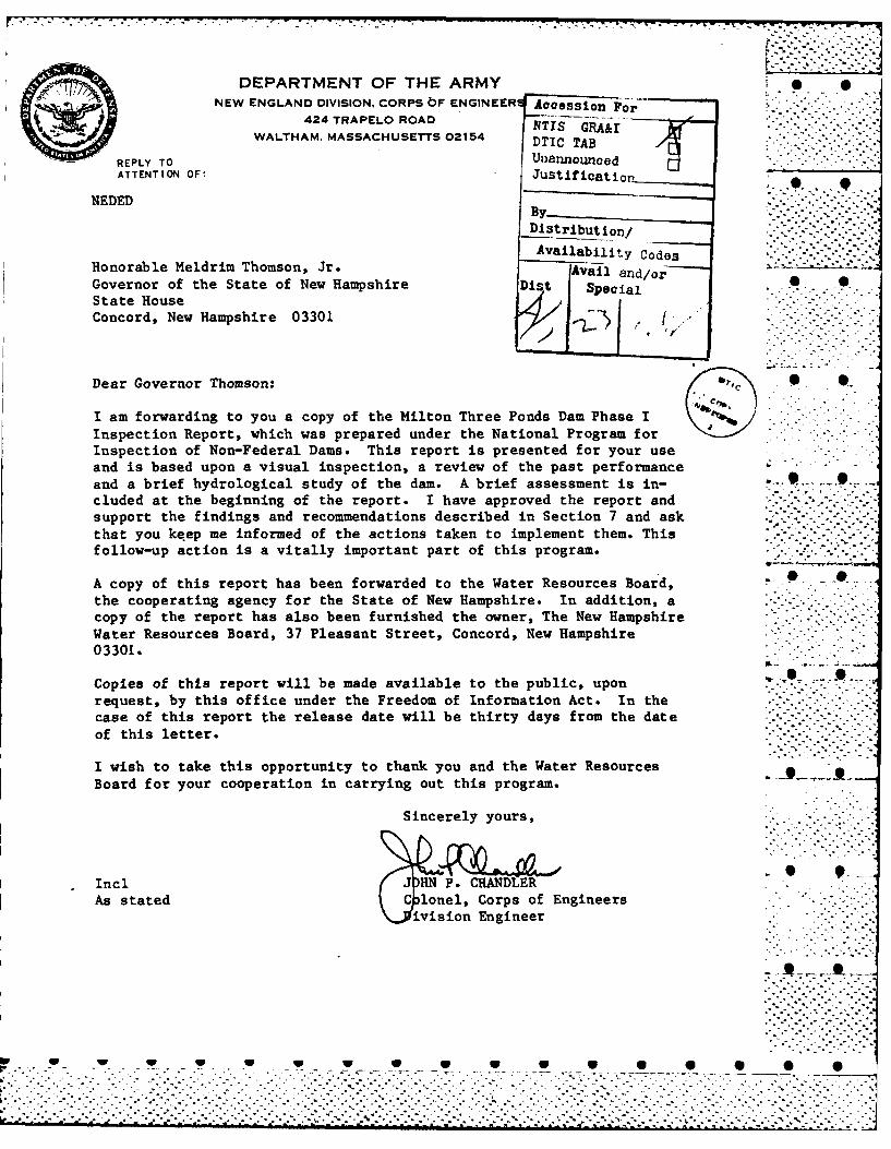
DEPARTMENT OF THE ARMY S SNEW ENGLAND DIVISION, CORPS bF ENGINEER Accession-
424 TRAPELO ROAD NTIS GRA&r
WALTHAM, MASSACHUSETTS 02154 DTIC TAB
U'nannounce
ATTENTION OF: Justificatio
NEDED .-
Distribution/
Availability CodesHonorable Meldrim Thomson, Jr. Vail and/orGovernor of the State of New Hampshire Dist Special 0
State House
I
_ ." i -'''''
-
Concord, New Hampshire 03301 / ,1--..*'
Dear Governor Thomson: • •
I am forwarding to you a copy of the Milton Three Ponds Dam Phase IInspection Report, which was prepared under the National Program forInspection of Non-Federal Dams. This report is presented for your useand is based upon a visual inspection, a review of the past performanceand a brief hydrological study of the dam. A brief assessment is in-cluded at the beginning of the report. I have approved the report andsupport the findings and recommendations described in Section 7 and ask . ..- --.t h a t y o u k e e p m e i n f o rm e d o f t h e a c t i o n s t a k e n t o im p l e m e n t t h e m . T h i s -''
follow-up action is a vitally important part of this program.
A copy of this report has been forwarded to the Water Resources Board, .the cooperating agency for the State of New Hampshire. In addition, acopy of the report has also been furnished the owner, The New HampshireWater Resources Board, 37 Pleasant Street, Concord, New Hampshire03301.
Copies of this report will be made available to the public, uponrequest, by this office under the Freedom of Information Act. In thec a s e o f t h i s r e p o r t th e r e l e a s e d a t e w i l l b e th i r ty d a y s f r o m th e d a t e ..:
of this letter.
I wish to take this opportunity to thank you and the Water ResourcesBoard for your cooperation in carrying out this program.
Sincerely yours,
Inc J N P. CHANDLERAs stated Corps of Engineers
vision Engineer
* -- :~ .:- .--......-- - --...... t..
...........................................
-.. .. .. .. ..... .. ... .. ... .. .. .. .. \.,°. -. °°°"0 . -. 0 .- ~ . d ... .. ~ .. - . - -s ° - . - - " % ° . '. ."
.-..- oo-..
. . . .-. .

MILTON THREE PONDS DAM
NH 00320 * ~-
PISCATAQUA RIVER BASINMILTON, NEW HAMPSHIRE
PHASE I INSPECTION REPORTN NATIONAL DAM INSPECTION PROGRAM
0 0 S S S 6 6 0 0 000 0 0 0 0 01 7

NATIONAL DAM INSPECTION PROGRAMPHASE I INSPECTION REPORT
*Identification No.: NH00320IName of Dam: Milton Three Ponds Dam* Town: Milton .*
County and State: Straf ford County, New HampshireStream: Salmon Falls River .
Date of Inspection: 19 June 1978. .. -
*BRIEF ASSESSMENT
N fMilton Three Ponds Dam is 19 feet high, is 16 feet wide, andis 156 feet long. It is a gravity dam, consisting of a drystone masonry bed over which a reinforced concrete
* superstructure has been built. The dam spans a middle reachof the Salmon Falls River, and is located in east centralNew Hampshire. It has two low-level outlet gates; thespillway extends across the length of the dam with 25 baysof stoplogs. Maximum storage capacity is about 15,000 acre-feet. Milton Three Ponds Dam is used for industrial process
*water as well as for recreational purposes. The pond is about5 miles in length with a surface area of about 900 acres.
" The dam is in good condition. Minor concerns are: the*displacement of a few large stones from the downstream face;
structural deterioration of the concrete, including cracking,oallling, and erosion that has exposed reinforcing bars; andspillwy seepage at the toe of the dam at the west abutment.
Based on size and hazard classifications in accordance withCorps guidelines, the test flood is the Probable Maximum Flood.With stoplogs in place a PMF outflow of 35,000 cfs (324 csm)would overtop the dam by 12.8 feet; therefore the spillwayis considered inadequate. With stoplogs, the spillway will".pass 1300 cfs or 4 percent of the PM . With stoplogs removed, ethe spillway will pass 23,700 cfs. A major breach at maximumpool would probably result in the loss of less than 10 livesand appreciable property damage.
The owner, New Hampshire Water Resources Board, shouldimplement the results of the recommendations given in Section - -
7.2. within 3 years after receipt of this Phase I inspectionreport. The operating and maintenance measures recommendedin Subsection 7.3.b. should be implemented within one yearafter receipt of this Phase I inspection reprt.
Warren A. GuinanProject Managerd...N.H. P.E. 2339
L2
The wne, Nw HmpsireWate Reoures oar, soul
* ! . . " . -.

This Phase I Inspection Report on Milton Three Ponds Damhas been reviewed by the undersigned Review Board members. In ouropinion, the reported findings, conclusions, and recommendations areconsistent with the Recommended Guidelines for Safety Inspectionof Dams, and with good engineering judgment and practice, and ishereby submitted for approval. -
CHARLES G. TIERSCH, ChairmanChief, Foundation and Materials BranchEngineering Division 9
FRED J. VO S, Jr., Member " eChief, Design BranchEngineering Division
SAUL COF embeChief, Water Control BranchEngineering Division
APPROVAL RECOMMENDED:
'JOE B. FRYARChief, Engineering Division -* _
...............................................................

--.- ,. .. . .. .. . .
PREFACE
This report is prepared under guidance contained in theRecommended Guidelines for Safety Inspection of Dams, forPhase I Investigations. Copies of these guidelines may be .obtained from the Office of Chief of Engineers (OCE),Washington, D.C. 20314. The purpose of a Phase I Investi-gation is to identify expeditiously those dams which may- ;."-
pose hazards to human life or property. The assessment ofthe general condition of the dam is based upon available
II data and visual inspections. Detailed investigation, and ,analyses involving topographic mapping, subsurface investi-gations, testing, and detailed computational evaluationsare beyond the scope of a Phase I investigation; however, ..
the investigation is intended to identify any need for suchstudies.
In reviewing this report, it should be realized that thereported condition of the dam is based on observations of
field conditions at the time of inspection along with data- available to the inspection team. In cases where the
reservoir was lowered or drained prior to inspection, suchaction, while improving the stability and safety of the P S
- - dam, removes the normal load on the structure and may
obscure certain conditions which might otherwise bedetectable if inspected under the normal operating environ-ment of the structure.
It is important to note that the condition of a dam depends t Son numerous and constantly changing internal and externalconditions, and is evolutionary in nature. It would beincorrect to assume that the present condition of the damwill continue to represent the condition of the dam atsome point in the future. Only through continued care and - .
I* inspection can there be any chance that unsafe conditions Sbe detected.
*-'. Phase I inspections are not intended to provide detailed.- hydrologic and hydraulic analyses. In accordance with the
established Guidelines, the test flood is based on theestimated "Probable Maximum Flood" for the region (greatest I Sreasonably possible storm runoff), or fractions thereof.Because of the magnitude and rarity of such a storm event,a finding that a spillway will not pass the test flood shouldnot be interpreted as necessarily posing a highly inadequate
,- condition. The test flood provides a measure of relativespillway capacity and serves as an aide in determining the S
. need, for more detailed hydrologic and hydraulic studies,considering the size of the dam, its general condition andthe downstream damage potential. -.
V ivL
0 0- 0 0 S 0 0 S 0 S S 0
7"% - %•.
-s x.4
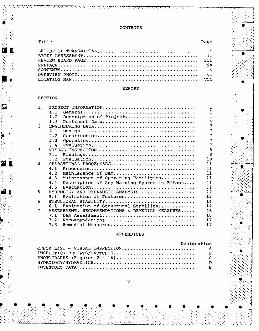
CONTENTS
Title P age
~~ I LETTER OF TRANSMITTAL.........................................iBRIEF ASSESSMENT.............................................. ii
REVIEW BOARD PAGE............................................. iii -
* - PREFACE........................................................ iv *.
CONTENTS........................................................V .-vOVERVIEW PHOTO................................................ vi *~ --S I LOCATION MAP.................................................. vii
REPORT
SECTION
1 PROJECT INFORMATION....................................... I-1.1 General................................................11.2 Description of Project...............................11.3 Pertinent Data....................................... 4
* 2 ENGINEERING DATA...........................................72.1 Design.................................................72.2 Construction.........................................72.3 Operation............................................ 72.4 Evaluation........................................... 7
3 VISUAL INSPECTION..........................................83.1 Findings............................................. 83.2 Evaluation........................................... 10
4 OPERATIONAL PROCEDURES................................... 114.1 Procedures........................................... 114.2 Maintenance of Dam.................................. 114.3 Maintenance of Operating Facilities............... 114.4 Description of Any Warning System in Effect . 114.5 Evaluation........................................... 11
~ [5 HYDROLOGY AND HYDRAULIC ANALYSIS........................ 125.1 Evaluation of Features............................. 12
6 STRUCTURAL STABILITY...........................14* . 6.1 Evaluation of Structural Stability.................14 -
7 ASSESSMENT, RECOMMENDATIONS & REMEDIAL MEASURES ... 167.1 Dam Assessment...................................... 16
S 7.2 Recommendations..................................... 177.3 Remedial Measures................................... 17
APPENDICES
DesignationS CHECK LIST- VISUAL INSPECTION............................... A
INSPECTION REPORTS/SKETCHES...................................BPHOTOGRAPHS (Figures 2 - 16)..................................CHYDROLOGY/HYDRAULICS...........................................DINVENTORY DATA..................................................E
v
. . . . . . . . . .. . . . . . . . . S

.* _)
Fiur Ovriwo Mlo heeP SDm
- *vi
W

Ae erboroA( Shapeig1
1*-ur AMIPgery 0oC
0221 A red*
/A orh, Agmeti
Canda Cada ~106,109-
* ~ ~~~~~~~~~~~ ntIO nC~lodNO30Od~~P;0~Or,nO,.t~rynnm..n o fe Oporm~ ofR~air*.endEcoenIe ndrso-NchosA L o hinc. U .AM NGNE I.NE NLN
/:11"CORP O1 ENGINEERSick9
b Mt
iDAT AUGUST 1978u'-6a
*R 0ln~o 0ot Berwick00 0 0 0
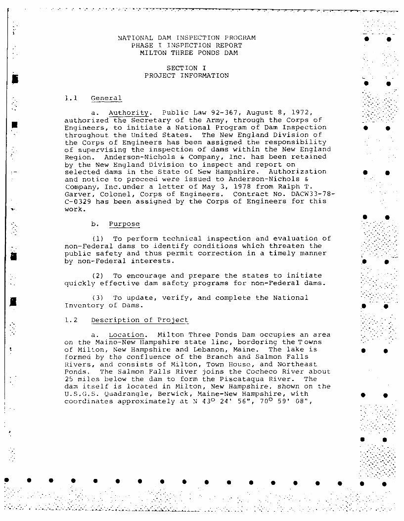
NATIONAL DAM INSPECTION PROGRAM 0 0PHASE I INSPECTION REPORTMILTON THREE PONDS DAM
SECTION IU PROJECT INFORMATION
1.1 General
a. Authority. Public Law 92-367, August 8, 1972,authorized the Secretary of the Army, through the Corps ofEngineers, to initiate a National Program of Dam Inspectionthroughout the United States. The New England Division ofthe Corps of Engineers has been assigned the responsibilityof supervising the inspection of dams within the New EnglandRegion. Anderson-Nichols & Company, Inc. has been retainedby the New England Division to inspect and report onselected dams in the State of New Hampshire. Authorizationand notice to proceed were issued to Anderson-Nichols &Company, Inc.under a letter of May 3, 1978 from Ralph T.Garver, Colonel, Corps of Engineers. Contract No. DACW33-78-C-0329 has been assigned by the Corps of Engineers for thiswork.
b. Purpose
(1) To perform technical inspection and evaluation ofnon-Federal dams to identify conditions which threaten thepublic safety and thus permit correction in a timely mannerby non-Federal interests.
(2) To encourage and prepare the states to initiatequickly effective dam safety programs for non-Federal dams.
(3) To update, verify, and complete the National .-. -/
Inventory of Dams.
1.2 Description of Project
a. Location. Milton Three Ponds Dam occupies an areaon the Maine-New Hampshire state line, bordering the Townsof Milton, New Hampshire and Lebanon, Maine. The lake isformed by the confluence of the Branch and Salmon FallsRivers, and consists of Milton, Town House, and NortheastPonds. The Salmon Falls River joins the Cocheco River about25 miles below the dam to form the Piscataqua River. Thedam itself is located in Milton, New Hampshire, shown on theU.S.G.S. Quadrangle, Berwick, Maine-New Hampshire, withcoordinates approximately at N 430 24' 56", 700 59' 08",
* S
. ."
Strafford County, New Hampshire. (See Location Map page vii.)
b. Description of Dam and Appurtenances. Milton ThreePonds Dam, as it exists today, is a gravity dam consistingof a dry stone masonry base over which a reinforced concretesuperstructure has been built. The dam is 19 feet high,16 feet wide, and 156 feet long. The concrete superstructureconsists of seven sections of stoplogs, a low-level gatedoutlet structure, and a reinforced concrete foot bridge.The seven sections of stoplogs are divided as follows: Fivesections of four bays each are located to the left (east) ofthe gate structure, a section of three bays of stoplogsoccupies a space vertically above the two-compartmentedgated low-level outlet, and a section of two bays right (west) 0of the gate structure. A wooden gatehouse has been constructedabove the three-bay spillway and contains the gate hoistingmechanisms. Two wooden gates, 27" H x 44" W, each fittedwith two timber stems with rack and pinion mechanisms areelectrically operated by a single motor with a transfer beltdrive.
c. Size Classification. Intermediate (Hydraulicheight - 18 feet; Storage - 15,000 acre-feet) based on storage(> 1000 to <50,000 acre-feet) as given in OCE Recommended
Guidelines for Safety Inspection of Dams. * 0
d. Hazard Classification. Significant hazard. A majorbreach at maximum pool would probably result in the loss ofless than 10 lives and appreciable property damage.
e. Ownership. The Great Falls Manufacturing Companypurchased the original dam and privilege in 1824. Ownership .of Milton Three Ponds Dam passed on to the Public ServiceCompany of New Hampshire sometime between 1922 and 1929.The New Hampshire Water Resources Board (NHWRB) acquired thedam and water rights in December of 1963.
f. Operator. Mr. Vernon K. Knowlton, Chief Engineer, . SNew Hampshire Water Resources Board, 37 Pleasant Street,Concord, New Hampshire 03301, is responsible for the operationof Milton Three Ponds Dam. Phone is (603) 271-3406.
g. Purpose of Dam. The original structure impoundingMilton Three Ponds Dam was constructed to provide greater Sindustrial water storage for downstream mills. Under theownership of the Public Service Company of New Hampshire,Milton Three Ponds Dam was utilized mainly as conservationstorage for the generation of hydro-electricity for theregion, with some recreational usage. Today, Milton ThreePonds Dam is used primarily for recreation, while also ._0providing water storage for downstream industries.
2- .
.....-..-.-...... .. .
*. . . . . . . ."j".
................................

h. Design and Construction History. Little informationwas disclosed concerning the original (circa 1824) designand construction of the dam. The dam is reported to havebeen modified 6 times in the next 91 years as follows: The __"_____"
dam was raised 4 feet in 1835 (called 9 feet high), raised6 more feet in 1835 and this 6 feet was removed in 1847.The latter 6 feet was reconstructed again at some unknownlater date. The dam was raised 2 feet more in 1872 (thencalled 16 feet); the cement facing and gateways were builtin 1915. (See Public Service Company of New Hampshire letterof 9/29/1949, Appendix B.)
In 1924, in correspondence to the New Hampshire PublicService Commission, I.W. Jones & Co., Engineers, reported"...the outlet of Milton Three Ponds. It is about 16 ft.in height by 136 ft. in length. It is composed of woodenbents set about 6 ft. on centers with a walk across the topfrom which 7 ft. of flashboards can be drawn. It is foundedon a rough stone wall, the upstream side of which is facedwith concrete. This dam was built in 1873 and the woodensheet piling originally placed at the upstream side wassubstituted by concrete about eight years ago. Plans havealready been made for replacing the wooden bents with 0O 0reinforced concrete. " (See Appendix B.)
The present outlet facilities at Milton Three Ponds wereconstructed in 1968 by the NHWRB.
i. Normal Operational Procedures. No formal operationaland maintenance procedures were disclosed. Normal poolelevation during the summer months is 413.8 feet MSL. Thislevel is maintained by keeping one of the two waste gatesopen 3 inches, supplying a minimum flow of 20-30 cfs fordownstream users, and setting the stoplogs at 15.2 feet onthe gage (413.8 feet MSL) upstream of the dam. After therecreational season the impoundment is drawn down approxi-,0mately 6 feet, to 9.0 feet on the gage (407.6 feet MSL) byremoving stoplogs. The dam is visited on a weekly basis bythe NHWRB. Telecommunication with the dam on a daily basis
L provides the NHWRB with information on discharge and lake level.
j. Regulating Outlets. The two reinforced concretelow-level outlets have downstream portal openings of about5' x 5' separated by a 30" wide central pier. The gatesare wooden, each is 27" H x 44" W, and they are fitted withtwo timber lifting stems. The gates can be raised 27 inches.
. .. . . . . . .. . . . . . . . . .. -..
. . . . . . . . . . . . . . . . . . . . . . . . .. . . . . . . . . . .
_Ao-__ _ _ _ _ _ _ _____.-°.
3~ -"i. -¢ '
L
1.3 Pertinent Data
a. Drainage Area. The drainage area consists of108 square miles (69,120 acres) of primarily wooded terrainwith some urbanized area. The normal recreation level has . pa surface area of 900 acres, which is equivalent to 1 percentof the watershed.
b. Discharge at Damsite
(1) Outlet Works (conduits) - Two 27" x 44" @ Invert p
Elevation 400.0 ft. + MSL. Total capacity - 380 cfs @413.8' MSL.
(2) The maximum known flood discharge at the damsiteis unknown. However, there was a gaging station on the SalmonFalls River at South Lebanon, Maine (D.A. 137 sq. mi.), andthe March 1939 flood produced a peak flow of 5490 cfs.
(3) Stoplog spillway capacity at recreational poolelevation (stoplogs in place) - 0 cfs @ 413.8' MSL.
(4) Stoplog spillway capacity at maximum pool elevation -
(stoplogs in place) - 1300 cfs @ 416.2'MSL.
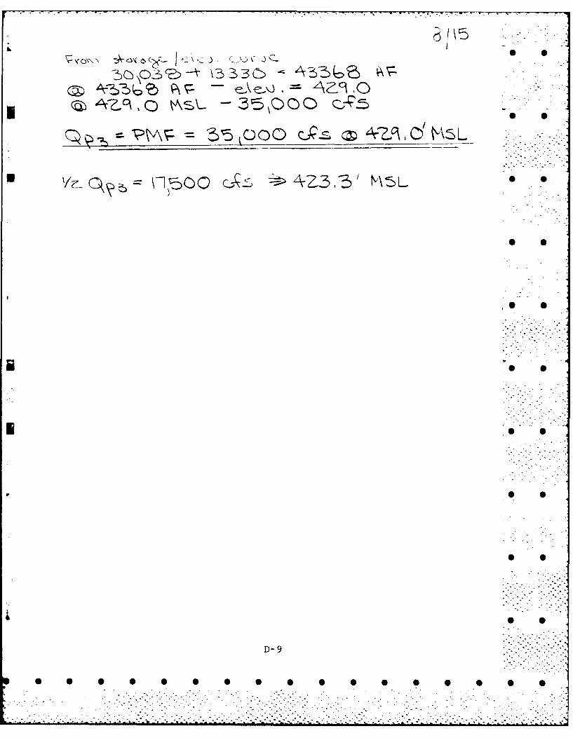
(5) Total project discharge at Test Flood elevation(stoplogs in place) - 35,000 cfs @ 429.0' MSL.
C. Elevation (ft. above MSL) -
(1) Top of dam -the crest varies from 416.2 to 417.6
(2) Test Flood pool - 429.0
(3) Design surcharge - original design - unknown
(4) Full flood control pool - not applicable
(5) Recreation pool - 413.8
(6) Top of stoplogs - 413.8 -
(7) Spillway crest - 408.3 (assuming stoplogs removed)
(8) Upstream portal invert low-level conduit - 400.0
(9) Streambed at centerline of main dam - 398.6 p(downstream invert of stilling basin measured 8/2/78)
(10) Maximum tailwater - unknown
4 •
• - . " " .' - , ., , . .4

d. Reservoir (miles) p
(1) Length of maximum pool - 5.0
(2) Length of recreational pool - 4.9
(3) Length of flood control pool - not applicable ) ,
e. Storage (acre-feet)
(1) Recreation pool - 12,500
(2) Flood control pool - not applicable
(3) Test flood pool - 43,368
(4) Top of dam - 15,000
- f. Reservoir Surface (acres)
(ii Top of dam - 1015
(2) Test flood pool - 2840
(3) Flood control pool - not applicable ,
. (4) Recreation pool - 900
(5) Spillway crest - 375
g. Dam 0
(1) Type - The structure is basically a gravity dambuilt on a stone foundation with steel stanchions and aconcrete superstructure.
(2) Length - 200' (from past inspection reports) 0- 156' (measured)
(3) Height - 19' (structural height)
(4) Top width - 16.5'
(5) Side Slop,,s - Vertical downstream; approximatelyIli:1 3/4V upstream, as shown on design plans
* .(6) Zoninq - unknown
(7) Impeivinis core - unknown
i!!!i!5. T. ill 0
0 0 0 S 0 0 0
(8) Cutoff - An upstream cutoff wall is reported tohave been placed in 1915. (See Appendix B.)
(9) Grout curtain - unknown
h. Diversion and Regulating Tunnel. The regulatingtunnels consist of two reinforced concrete boxes approxi- -
mately 5' x 5' separated by a 30" pier. The tunnels arefitted with gates 27" H x 44" W.
i . Spillway
(1) Type - Concrete spillway with 25 bays of stoplogs.
(2) Length of weir - 126.25' (20 bays @ 5 foot lengths;2 bays @ 6 foot lengths and 3 bays at approximately 5 footlengths.)
(3) Crest Elevation - 408.3' MSL (22 bays on eitherside of gatehouse); 409.6' MSL (3 bays above low-level outlet) "
(4) Gates - not applicable
(5) U/S Channel - Milton Three Pondsw-3
(6) D/S Channel - bottom is covered with sand, gravel, .and boulders.
(7) General - The 20 bays of stoplog spillway to thewest of the gatehouse are comprised of 5 sections separatedby 18" wide concrete piers. Each of the above sections isdivided into 4 bays separated by 10" wide steel stanchions, " •and are at invert elevation 408.3' MSL. The 2 bays ofstoplog spillway to the east of the gatehouse are alsoseparated by a 10" wide steel stanchion, and at invertelevation 408.3' MSL. The 3 bays of stoplog spillway belowthe gatehouse are separated by 30" wide concrete piers.These latter bays are at invert elevation 409.6' MSL. . -
A four foot wide reinforced concrete walkway has been built
over the stoplog spillways on both sides of the gatehouse.
This access bridge is 1.5 feet thick. The top of the walkwayis at elevation 417.6' MSL.
6
0 0 0

SECTION 2ENG LNEEJING DATA i.
2. Design
A search of the files of the New Hampshire Water ResourcesBoard disclosed only a limited amount of recorded information .concerning the design of the present outlet facilities atMilton Three Ponds Dam. Plans of the dam re-constructionin 1968 were found and used in the hydraulic computations.(See Appendix D.)
2.2 Construction S 0
No pertinent information regarding the actual constructionof the present outlet structure at Milton Three Ponds Damwas disclosed.
2.3 Operation I S
No formal operational procedures were disclosed. However,correspondence reflecting past operational practice werediscovered and validated.
2.4 Evaluation S .
a. Availability. Only a limited amount of data onthe actual design and construction of Milton Three PondsDam were disclosed.
b. Adequacy. The information obtained from extensive 0data collection efforts was not adequate in determining thehydraulic characteristics of Milton Three Ponds Dam.
Supplemental data established by field investigation wasneeded to complete the hydraulic analysis. Because of thelimited amount of detailed data available, the finalissessments and recommendations of this investigation are .i)ased on visual inspection and hydrologic and hydraulicina lys is.
c. VaIidi t. The visual inspection is consistentwith the 1968 re-construction plans.
7 . . . . ..
-. . .. . . -.
SECTION 3 0 0VISUAL INSPECTION
3.1 Findings
a. General. The dam is classified a low dam and S 0impounds an intermediate-size reservoir. The downstreamarea is sloping and generally open. The USGS has constructeda concrete gaging weir approximately 150 feet downstream.The watershed above the reservoir is heavily wooded.Numerous buildings and homes are located around the perimeterof the reservoir. A vehicular bridge crosses the upstream •channel approximately 150 feet upstream from the dam, anda single track railroad bridge also crosses the upstreamchannel approximately 600 feet upstream from the dam.
b. Dam. The dam was originally built as a combina-tion timber crib dam and dry stone masonry, and according S Sto available correspondence, the dam was increased inheight several times to its present height. The upstreamcutoff wall was placed in 1915 and the upper timber cribwork was replaced with the present concrete channel, catwalk,and stoplog sections in 1968. (See Appendix C - Figures 2,3 and 4.) The entire dam above the dry stone masonry base • _consists of stoplog sections. The stoplogs must be manuallyremoved.
The dry stone masonry base indicated only two minor areasof distress on the downstream face, where rocks had becomedislodged from the face. S
Two openings were observed in the downstream face of thedry stone masonry base which were low-level outlets thatwere used at one time. The old openings have a dry masonryarch and appear to be plugged some distance behind thedownstream face. The present low-level outlet structure • Sis made of concrete and is located near the west abutment.
A portion of the east abutment has been refaced withconcrete. The exposed surface of the older concrete hasdeteriorated little with only the loss of surface laitance,exposure of some of the coarse aggregate, and minor 0 0cracking. (See Appendix C - Figure 6.) The top of theoriginal abutment and one portion of the downstream facehas spalled and deteriorated to a depth of approximately1 inch. (See Appendix C - Figure 7.) Minor movement (lessthan .10 inch) has occurred between the original concreteabutment and the new concrete stoplog structure. Exposed Sreinforcing was noted in the base of the stoplog slot above
8
5 0 S 0 0 S 0
-. . . . . . •

the water line.
The most severe deterioration of the counterfort wall hasoccurred on the first wall from the left abutment.Approximately 3 inches of the downstream end of the toe ot5 the wall has spalled. (See Appendix C - Figure 8.) Minorloss of surface laitance has occurred on the counterfortwalls and spillway apron where the concrete is in continuouscontact with the water, exposing some of the coarse aggregate.Evidence of undercutting was noted at the joint between thebottom of the counterfort wall and the base slab. However,the visual inspection could not determine the depth ofundercut or effect on the vertical wall reinforcing.
One minor seepage was noted on the downstream face near thecontact of the right (west) abutment and the earthembankment.
C. Appurtenant Structures. Low-level control of thedam is accommodated by two sluice gates, 27 inches high by44 inches wide, with wooden lifting stems. The gates areelectrically operated from one electric motor. The gateequipment appeared to be well maintained and is consideredto be in good condition. The electrical service wasobserved to be of adequate size for the given requirements.It was noted that the wiring within the gatehouse is
exposed romex wire without double grounding features. Thegatehouse appeared to be in good condition.
i ~The concrete walls and base slabs of the gate structure are ,"-''
concrete. The surface of the concrete has eroded anddeteriorated from continuous contact with water which hasexposed the surface of the coarse aggregate. (See AppendixC - Figure 5.) Visible portions of the concrete mass didnot indicate any evidence of movement or instability.
The exposed steel stoplog support beams and embedded angleshad not been painted and revealed some surface corrosion,although it did not appear to impair the structuralcapability of the supports. (See Appendix C - Figure 9.)The stoplogs were noted to be in good condition except forsome leakage through the joints and around the ends of thestoplogs.
The concrete service bridge was observed to have one minor .- .-. ' .
longitudinal crack in the vicinity of the embedded wideflange beam, and one expansion joint is deteriorating and " 'spalling the surrounding concrete. (See Appendix C -
Figures 10 and 11.)
9 I 0
............................................ .......................................................... ...............

d. Reservoir Area. The reservoir slopes are gently S Sto steeply sloping and are generally covered with trees andbrush. Some .pen land, in the form of fields and roadways,is adjacent to the reservoir. Numerous buildings, cottages,and homes are located around the lake. Two bridges traversethe upstream channel; a vehicular bridge approximately 150feet upstream of the dam (See Appendix C - Figure 12.) and I 0a railroad bridge approximately 600 feet upstream. (SeeAppendix C Figure 13.) The east shore of the upstreamchannel is generally covered with trees and brush. (SeeAppendix C - Figure 14.) One house is located on the eastbank, just upstream of the vehicular bridge. Buildingsalong the west shore are built on the edge of the channel. - 0
e. Downstream Channel. The bottom of the channeldownstream of the dam is covered with sand, gravel, and . -boulders. The channel is generally clear of debris. Aconcrete gaging weir has been constructed across the channelapproximately 150 feet downstream of the dam. Trees and •brush are growing adjacent to the channel. (See AppendixC- Figure 16.)
3.2 Evaluation
Based on the visual inspection, the condition of the Milton •Three Poh.ds Dam is good. The potential problems observedduri:.g the visual inspection that may affect the long-termintegrity of the dam are as follows:
(1) Large stones that have been dislodged from thedownstream face of the dry stone masonry base;
(2) Minor deterioration of the concrete stoplogstructures including local spalling and erosion of concrete,loss of surface laitance, exposure of reinforcing;
(3) Corrosion of steel stoplog support beams and 1 7embedded angle iron;
(4) Small displacement between old and new concreteon the upstream face at the left abutment;
(5) Small crack in the service bridge deck ; and 0 0
(6) Electrical work in the gatehouse is not doublegrounded.
10
* 0 0i0 0 0 0'0 0 0" 0 0"0 '
• ~~~. /-.'-

SECTION 4OPERATIONAL PROCEDURES
4.1 Procedures
No formal operational procedures were disclosed. The dam 0.has been owned and operated by the NHWRB since December of1963. During the summer months, the lake level is main-tained by setting the stoplogs at 15.2 feet on the gage(413.8 feet MSL) upstream of the dam, and keeping one ofthe two waste gates open 3 inches. In this manner aminimum flow of 20-30 cfs can be supplied to downstreamusers.
After the summer recreational season the pool is drawn down6.2 feet by setting the stoplogs at 9 feet on the gage (407.6feet MSL). Stoplogs are removed from 6 bays so as to graduallylower the lake level. The dam is visited on a weekly basisby the NHWRB.
4.2 Maintenance of Dam
No formal maintenance procedures were disclosed. The NHWRBis responsible for maintaining the dam at Milton Three Ponds.
4.3 Maintenance of Operating Facilities
No formal maintenance schedule for operating mechanismsI was disclosed. Both gates are operated in the spring;
maintenance is performed at this time if deemed necessary. P 0
. 4.4 Description of Any Warning System in Effect
No description of any warning system was disclosed.
4.5 Evaluation P 0
The operating and maintenance procedures for Milton ThreePonds Dam, consisting of a weekly program of inspection,should insure that all problems encountered can be remedied -.-.
within a reasonable period of time. The NHWRB should also .- '"".establish a surveillance and warning program to follow in S Sthe event of floodflow conditions or imminent dam failure.
f S11.
*:)}ii??:: :i
0]. 0

SECTION 5HYDROLOGIC AND HYDRAULIC ANALYSIS
5.1 Evaluation of Features
a. Design Data. No original hydrologic and hydraulicdesign data (circa 1824) were disclosed for Milton ThreePonds Dam. However, hydrologic and hydraulic information,dating from the ownership of the structure by the PublicService Company of New Hampshire to the present ownershipby the New Hampshire Water Resources Board, were found andassessed to determine their acceptability in evaluatingthe overtopping potential of Milton Three Ponds Dam.
b. Experience Data. No information regarding pastovertopping of Milton Three Ponds Dam was disclosed.
c. Visual Observations. No visual evidence wasdisclosed of damage to the structure caused by overtoppingat the time of the inspection.
d. Overtopping Potential. Milton Three Ponds Damis classified as being intermediate in size having a maximumstorage of 15,000 acre-feet. The normal recreation levelhas a surface area of 900 acres, which is equivalent to 1percent of the watershed.
To determine the hazard classification for Milton Three PondsDam, the impact of failure of the dam at maximum pool was -. .. -
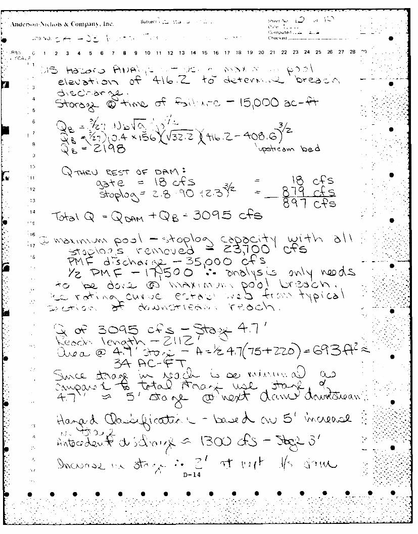
assessed using Guidance for Estimating Downstream Dam FailureHydrographs issued by the Corps of Engineers. The analysiscovered the reach extending from the dam to the Milton LeatherBoard Company Dam in Milton, New Hampshire, a distance ofabout one-half mile. Failure of Milton Three Ponds Dam atmaximum pool would probably result in an increase in stageof approximately 2 feet along the reach and may cause appreci-able damage to the Milton Leather Board Company Dam and otherlands in the reach.
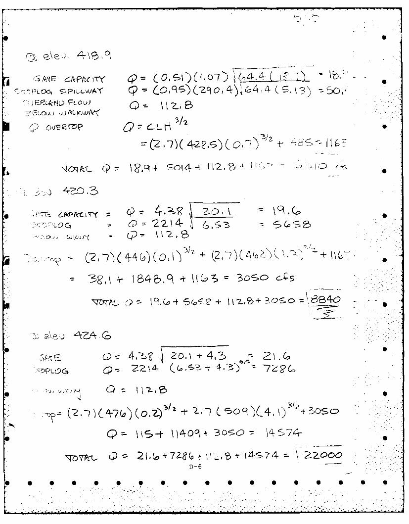
As a result of the analysis described above, Milton ThreePonds Dam was classified - Significant Hazard. Using OCERecommended Guidelines for Safety Inspection of Dams, therecommended spillway test flood is the Probable Maximum?lood. The test floow inflow for Milton Three Ponds Dam,naving a drainage area of 108 square miles, was determinedzo be 42,660 cfs (395 csm). The test flood discharge afterrouting was determined to be 35,000 cfs (324 csm).
12* S
. . .. . . .. . . . . . . . . . .°
. . . . . .. . . . . . . . . . . . . . . . .. .. • .

Milton Three Ponds Dam is unable to pass the test flood 0
without overtopping. Because the stoplogs would be difficultto remove during a flooding event of this magnitude, the testflood was calculated assuming stoplogs in place. The waterdepth over the dam embankment was calculated to be 12.8 feet.The spillway capacity, with all stoplogs removed, is approxi-mately 68 percent of the test flood.
13. --. . S
-. . - - . - .
* S
.... " ..1.. •
SECTION 6 0 SSTRUCTURAL STABILITY
6.1 Evaluation of Structural Stability
a. Visual Inspection. The visual inspection revealeda condition which could lead to structural instability. Afew stones appear to have fallen out of two areas of thedownstream face of the dry masonry base on which the concrete - -. --.- .. -.
stoplog structure rests. Further deterioration of the drymasonry base would have an adverse effect on the stabilityof the dam. -*
Minor deterioration of the concrete stoplog structure wasobserved, including local spalling and erosion of concrete,loss of surface laitance, rusting of some upstream stoploganqle irons, exposure of some reinforcing in the concrete,a small displacement between old and new concrete on the 0 0upstream face at the left abutment, and a small crack inthe service bridge. Proper maintenance should prevent theseconditions from developing into a serious stability problem.
One minor seepage was observed at the contact between thedam and the west abutment.
b. Design and Construction Data. Available datashow the dimensions of the concrete stoplog structure.However, no detailed information was available concerning -
the dry masonry base under the concrete stoplog section orthe concrete cutoff wall that was apparently poured againstthe upstream side of the dry masonry base. Therefore, theevaluation of the structural stability must be based primarilyon the results of the visual inspection.
c. Operating Records. No operating records pertinentto the structural stability of the dam were disclosed.
d. Post-Construction Changes. According to a letter.:i::en by the Public Service Company of New Hampshire onSeptember 29, 1949, the original dam was constructed at some,irknown date prior to 1824; the dam was raised 4 feet in1335 and was then called 9 feet high; the dam was raised 6 0!::-et more in 1835 and this 6 feet was removed in 1847 andireplaced at some unknown later date; the dam was raised 2feet more in 1872 and was then called 16 feet high; and the
" 2ment facing" and gateways were built in 1915. The concrete.;touiog structure which comprises the top section of the damolav, was built in 1968. 0
14
0 0 S S S 0 S -

. . . . . . . . . . . . . .. . . .
e. SeismicStability . This da.,t is in Seismic Zone 2and hcnce does not have to be evaluatud for seismic stability.in accordance with the OCE Recommended Guidelines.
15S

SECTION 7 SASSESSMENT, RECOMMENDATIONS & REMEDIAL MEASURES
7.1 Dam Assessment
a. Condition. The visual inspection indicates that . S "Milton Three Ponds Dam is in good condition. The spillway,although unable to pass the test flood without causingovertopping of the dam, is not considered seriouslyinadequate.
The displacement of a few rocks from the downstream face - S 0of the dry masonry base does not appear to have significantlyaffected the stability of the dam as of the time of thevisual inspection. However, this condition should bemonitored and repairs should be made if there is evidenceof any further deterioration of the dry masonry.
Minor structural deterioration, including cracking, spalling,and erosion of concrete, exposure of reinforcing bars, loss --
of surface laitance of conrete, a crack in the servicebridge, and rusting of the upstream stoplog angle ironsshould be remedied as part of the routine program ofmaintenance. •
A minor seepage at the contact between the dam and the westabutment does not appear serious. It should be monitored * "...-.and remedial action taken if needed. -..-...
The mechanical and electrical equipment appear to be in S .good condition.
b. Adequacy of Information. The information availableis such that the assessment of the condition of the dam mustbe based primarily on the visual inspection.
c. Urgency. The recommendations made in 7.2 belowshould be implemented within 3 years after receipt of thisPhase I report by the owner. The operating and maintenanceprocedures given in 7.3 below should be implemented withinone year after receipt of this Phase I report by the owner.
d. Need for Additional Investigation. The informationavailable from the visual inspection is adequate to identifythe potential problems which are: overtopping, displacementof rocks from the downstream face, minor structural deteriora-tion, and seepage. These problems require the attention ofa competent engineer who will have to make additional -engineering studies to design or specify remedial measures
16-. .
.......................-.... . ...
to rectify the problems. If left unattended, the problemcould lead to instability of the structure.
7.2 Recommendations
The NHWRB should evaluate further the hydraulics andhydrology of dam and increase the spillway capacity, if S -necessary.
7.3 Remedial Measures
a. Alternatives. The NHWRB should, as a practical - 0alternative pending implementation of the above recommenda- -..
tions, operate the reservoir at lower levels so as toprovide more storage for extreme flood events.
b. Operating and Maintenance Procedures.
(1) Repair annually and maintain the structure toeliminate the effects of cracking, spalling, erosion, andloss of surface laitance of the concrete, and rusting ofthe stoplog angle irons.
(2) Monitor on a weekly basis the minor seepage atthe west abutment and the condition of the dry masonry base. 0
(3) Replace the romex wiring inside the gatehousewith a steel conduit with insulated conductors and a greengrounding conductor (double insulating).
(4) Provide around the clock surveillance during 0 0periods of unusually heavy precipitation.
(5) Establish a warning system for alerting downstreamresidents in case of a flood emergency.
(6) Immediately develop flood regulation procedures 0 .relating to the operation of the sluice gates, removal ofindividual stoplogs, and the removal of stoplog sectionsunder emergency flood conditions. This procedure could bebased on rainfall, lake levels or a combination of both.
(7) Continue periodic inspection systems on a bi-annual . 0 .frequency.
17• . - - -
* 0 0 0 0,0 0"0 0 0 0 .0 -0-
................................................................. -.
7 -~
4 ... ,* ~ ~: t..tts> vi.
1>7 ~ ~ 7t7.t'~> ~ *. ~i.i*** . - * S
C.I.
S.
S S
* 0
IC APPENDIX A
* S
CHECK LIST - VISUAL INSPECI!ION
-4;
a. * 0I S
C.-. -
* S
A . . -
(7-7
V.- 4 . . .
0 0
K.
* S
I,
L
* 0 0 0 0 0 0 0 0 0 0 0 0 0 0 0 0 0

VISUIAL INSPECTION CHECKLIST
PARTY OR GAN IZATION
pHO)jFCT Milton Three Ponds Dam, N.H. DlATE J une 19, -197 8
TflC1 2:00 P.M.
WRATHERB Sunny,_ hot
W.S. ELEV. 413.8 iJ.S.398,.DN.S.
U PA RTY:
1. Warren Guinan 6. Harold Wilcox (6 jung- 1q7R)
2. Robert Langen 7.
3. Step~hen Gilmnan 8. S
4+. Ronald Hirschfeld 9.
5. John Falcione (6 June 1978) 10.
PROJECT FEATURE INSPECTED BY REMARKS
I.Hydrology/Hydraulics R. Langen
2.Structural Stability S. Gilman
3.SOils & GlgYR. Hirschfeld S
4.Mechanical J. Falcione
5r* Electrical H. Wilcox
6.
7.
10.
PR(OJE.CT Milton Three Pnndq fl~n. N i-. DATE June 19- 1978
Fp-JVCT FEATURE Dam Embankment NAW__
D ISCI PLINE_______________ NAME~
AMUA EVALUATED CONDIT iONS
DAM i RANKMETNT S 0
Crest Elevation Good, see attached notes.
Curr-ent Pool Elevation
Maximum Impoundment to Date 0
:'rfface Cracks
Pavement Condition
Movement or Settlement of Crest
Lateral Movement
Vertical Alignme~nt
horizontal. Aligiiment-
Condition at Abutment and ot Concretestruictures
In~dications of :-'ovement of Structural No visible movement. --
Items on Slope.s
2 evpassing on S3lopes
-loughing or Erosion of Slopes or
ocki Sl~ope Protection - Riprap Failures
jjnueual Movement or Cracking at orPco Toes
Unusual Embankment or Downstr'am6ee pag
K4oing or Boils
- islion Drainage Features
A- 2

• . 2PROJECT Milton Three Ponds Damn. N.H. I,,_June I. 17 k
PnOJECr }TATURF Upstream Chann1L NAH
DISC TD'L IE__ NA
AREA EVALUATED CONDITION
OUTII.T VORK - flTAKE CHAhE,. ANDmi INTAq STRiKVI'Uh~E
a. Approach Channel
Slope Conditions Gentle slopes covered with grass, trees andbrush, vertical slopes at buildings
Bottom Conditions Not visible
Rock Slides or Falls None
Log boom None
Debris None
Condition of Concrete Lining Not visible
Drains or Weep Holes None
b, Intake Structure "*e S
Condition of Concrete Surface laitance eroded
Stop Logs and Slots Good conditicn, sore leakage
A-3* S S S 0 0 S S 0 0 0 5 5 5 0
.. " <] l[ 'i*1
K.PERIODIC IDL}1ECTI, C i L1"1 T - -
PROJECIJ Milton Three Ponds Dam, N.H. iTF June 19, 1978
Pk'.JECT FEATURE Control Tower NA
DISCIPL]INE NAME _-_--____
AREA EVALUATED CONDITION
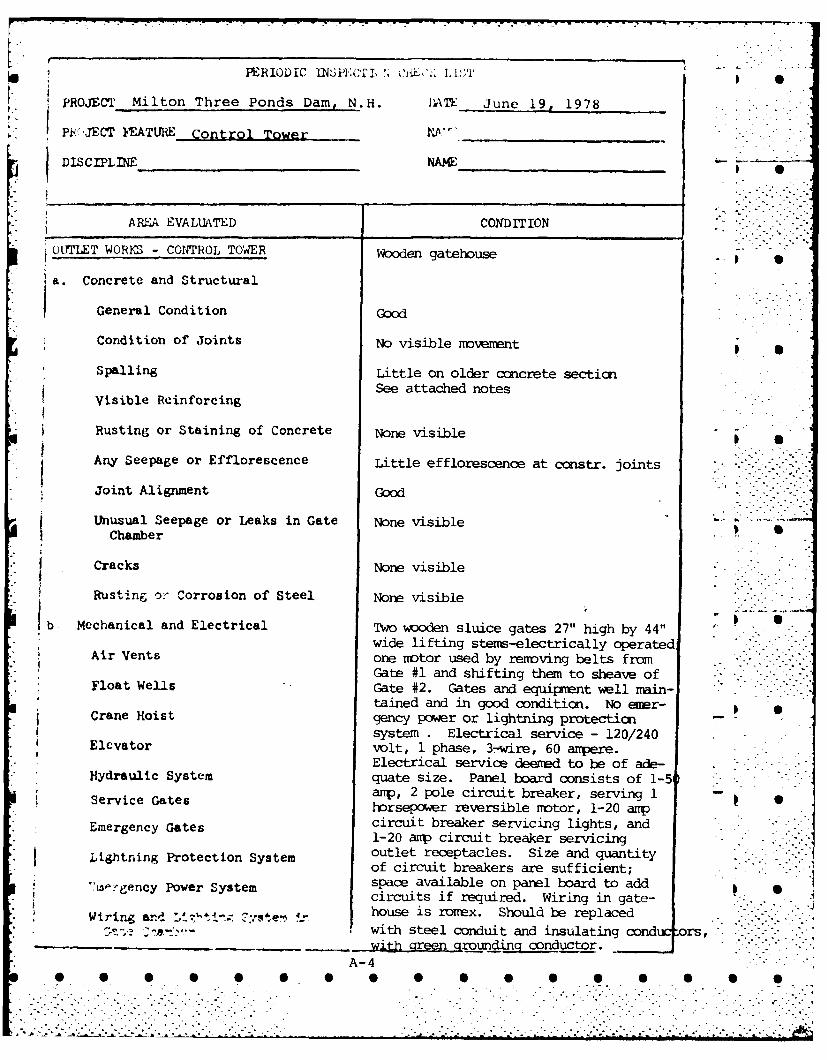
OtTFLET WORU - CON0TROL TOWER Wooden gatehouse
a. Concrete and Structural
General Condition Good
Condition of Joints No visible movement
Spalling Little on older concrete sectionSee attached notes
Visible ReinforcingRusting or Staining of Concrete None visible
Any Seepage or Efflorescence Little efflorescence at constr. joints " .* . . -
Joint Alignment Good'
Unusual Seepage or Leaks in Gate None visibleChamber
Cracks None visible
* Rusting o- Corrosion of Steel None visible
b, Mechanical and Electrical Two wooden sluice gates 27" high by 44"wide lifting stems-electrically operated
Air Vents one motor used by removing belts fromGate #1 and shifting them to sheave of *"._.
Float Wells Gate #2. Gates and equipment ell main-tained and in good condition. No eer-
Crane Hoist gency power or lightning protection - -system . Electrical service - 120/240
Elevator volt, 1 phase, 3-wire, 60 ampere.Electrical service deemed to be of ade-
Hydraulic System quate size. Panel board consists of 1-5amp, 2 pole circuit breaker, serving 1
Service Gates horsepower reversible motor, 1-20 amp
Emergency Gates circuit breaker servicing lights, and1-20 aip circuit breaker servicing
htning Protection System outlet receptacles. Size and quantity ... -of circuit breakers are sufficient;
is,,.rgency Power System space available on panel board to addcircuits if required. Wiring in gate-
Wiring and i-.: 7Vste-' house is rorrex. Should be replaced. .with steel conduit and insulating cond -ors,
with green groundin2 conductor.A-4

* 1 .T~~~~~ERuDIC ~ ~ (z~~K1~
PHOJFOT Milton Three Ponds D~am, NH. D)ATF June 19, 1978
* PROJECT FEATURE Outlet Conduit A2_______________
DISCIPLINE___NAME________
AREA IEVAIUATIhO COYDITION
O1YrLET WORKS - TBANSITION AI%'D CONDUTT Not visible
General Condition of Concrete 0
Rust or $taining on Concrete
Spalling
*Erosion or Cavitation -0
Cracking
Alignment of Monoliths
Alignment of Joints 0
Nuambering of Monoliths ,-
A- 5

.7.?Milton Three Ponds Dam, N.H. DAh June 19, 1978
P&CTYEATMhE Stoplog Structure ___________
> INE______ ____ NAME________
AHZLA kEVA],UATEDr CONDITION
0"?, ;T ,dURKc - OU1'LET STi-HUC-TIJRE AND
Ou:lraT CHANNEL
General Condition of Concrete Good
(urt or Staining None visible
So~ilingLittle on old concrete
E .ros ion or Cavitation Little visible
Visible Reinf'orcing None visible
An'y Seepage or Efflorescence None visible
Condition at Joints Good -no visible movement
Drain holes None
Channel.
Loose Rock or Trees Overhanging A few trees at edges of wideChannel discharge channel
Condition of Discharge Channel Good
0~~~~ 0

I~~~~~ ~ ~ ~ 'E DIS' "IJ Ii t
PROJI:CT Milton Three Ponds ',)am, N.H. DATE~ June 19, 1978
PROJELc1 11:ATURE Spillway Weir N~___________
DISC fl-1LlE________________ _____________
ARkA EVALUA'YD COND)ITION
OUYILET WOR~KS - SP1JiL'qAY WEIR, APPROACH- AIM DISCHARGE C 11ANHJELS
a. Approach Channel
General Condition Good
Loose Rock Overhanging Channel None
*Trees Overhanging Channel A few on both banks
Floor of Approach Channel Not visible
b. Weir and Training Walls
General Condition of Concrete Generally good-see attached notes
Rust or Staining
[Spaliing Little
Any Visible Reinforcing
* Any Seepage or Efflorescence
*Drain Holes None observed
c. Discharge Channel
*General Condition Good
Loose Rock Overhanging Channel None observed
Trees Overhanging Channel Some on west bank
Floor of' Channel Boulders, sand, gravel
Other Obstructions Measuring weir downstream of dam
A- 7
POJECT__Milton Three Ponds Dam, N.H. DT June 19, 1978
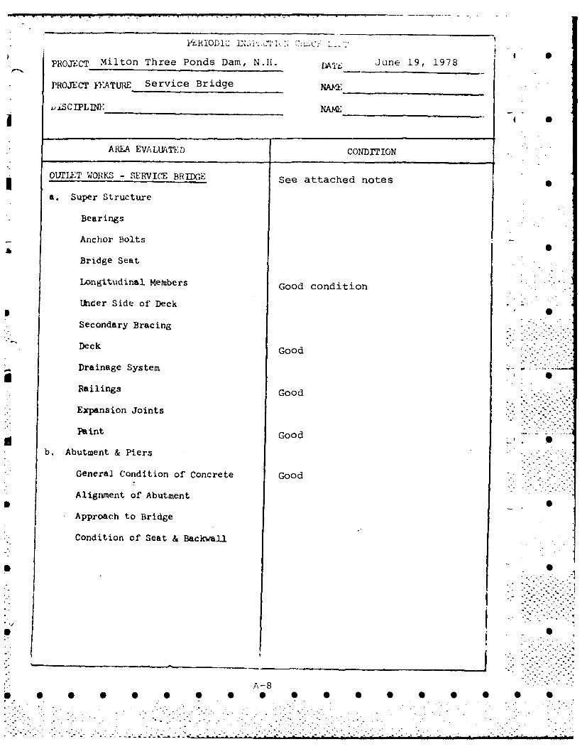
PROJECT IVATURE Service Bridge XM
AREA EVALUtkThr CONDITION
OUTULT WORKS - SERVICE B3RTIDGE See attached notes
a. Super Structure
Bearings
Anchor Bolts
Bridge Seat
Longitudinal Metibers Good condition
lkider Side of Deck
Secondary Bracing
Deck Go
Drainage System
Railings Good
Expansion Joints
Paitnt Good
b. Abutment & Piers
General Condition of Concrete Good
Alignment of Abutment
Approach to Bridge
* Condition of' Seat & Backwall
0 0 0 0 * 0 0 0 0 B 5

PROJECT Milton Three Ponds Dam, NH DATE June 19, 1978
PROJECT FEATURE Reservoir iA y1_R. Lanen _ _n
AREA EVALUATED REMARKS
Stability of Shoreline Good
Sedimentation No visible problems 5 5
Changes in Watershed MinorRunoff Potential
2 road bridges and 1 RR bridgeUpstream Hazards with small vertical opening;
building at pond edge on west sideDownstream Hazards
Several dams on river downstream
Alert Facilities None observed
Hydrometeorological Gages Staff gage S .
Operational & Maintenance None observedRegulations
* "
p 0
p. 0
p S
A-9
S 0 0 0 0 0 0 0 S S 0 0 0 0 0 S 0

MILTON THREE PONDS DA-MADDITIONAL NOTES
Monolith #1 - Left Abutment
1. The monolith is cast against the concrete abutmentplaced there many years previous. New concrete - goodcondition.
2. There is evidence of movement - open crack betweennew concrete and old on upstream face.
3. There is some spalling of cap on old concreteabutment. Old and new concrete that is now or has beensubmerged has lost surface laitance.
4. Upstream stoplog slot has exposed reinforcing -little rusting and staining.
5. Downstream face has tie holes left unfilled.
6. Joint at end of service bridge and abutment - 0some spalling. .
Monolith #2
1. Downstream end spalled/eroded - reinforcing exposed.
2. Surface laitance gone where exposed to moving water.
3. Expansion joint in service bridge is spalling - jointmaterial deteriorating.
4. There is visual evidence of little eroding of concrete O
at the base of wall and slab.
5. Some rusting of embedded stoplog angle iron.
Monolith #3, #4, #5, #6, #7
1. Some eroding of concrete at wall/slab joint
2. Some eroding at end of Monolith wall end
3. Generally good condition
4. Surface laitance gone on concrete
5. Exposed joint at #5 - caulking gone; cork exposed.
A-10
. . . . • , • • • . . . ° . . .. •...... . . • <.- -. . . .. . . . A**-~t ~ 2 S -a
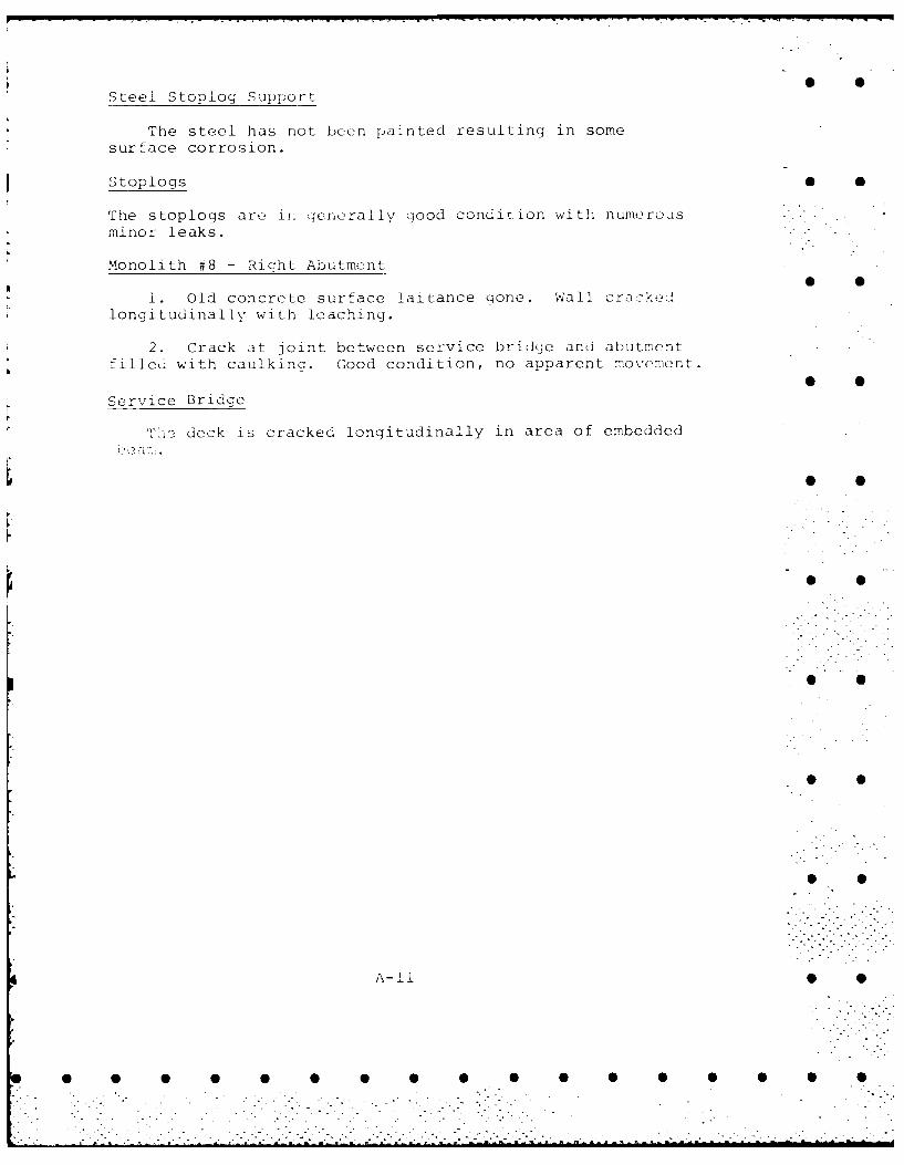
Steel Stoplog Support
The steel has not been painted resulting in some
surface corrosion.
Stoplogs 0
The stoplogs are il genrally good condition with numerousminor leaks.
L
Monolith #8 - Right Abutment
1. Old concrete surface laitance qone. Wall crackedlongitudinally with leaching.
2. Crack at joint between service bridge and abutmentfilled with caulkinq. Good condition, no apparent movement.
Service Bridge
7' deck is cracked longitudinally in area of embedded
A-l -1
S 0 S 0 S S 0 5 S S S S 5 5 S

* S
* 0
* S
* S
* 0~
* S
* S
* S
* S
S S
S S 5 S 0 5 5 5 S 5 0 S S 5 5

;'Z. AiLSI{ RE *diATEPT CONTROL MC!.'ISS ION
REPORT ON DAY INSPECTION
OJC'4N DA,. 11.0. _ __STREAN ~ ~~
O'.'WR ,~u~~; r ,A44 7 ADDRESS ~,.~
in a~cordiince wi~th Section 20 of Chapter 133, Lawts of' 1937, -che abovedpxn v;,Rs inspected by me o___/__,/___
LNOTES ON PHYSICAL COflITICN'Abu.t~nents _______________________
Spill way ____ 6 ,-
Ga t es ____ ___ ____ __- /. _ __ _ __ _ ___C_
Other
C.Ht~rES SIiZCE LAST iI'SPECTION ______________________
FUiTU--.E IlISFECTICYS___________________!
This dFn (is (4. arenace because
~~~~~1 4 4~'~ 4-Lc ~ _____

1037 E1zi Street CONTRACTOR NO.
=~~~k ?a cester, N. ~ __________ _____
INVESTIGATED BY ~ DATE
APPLICATION . ... A .
O AM F- ROPEALY C01NSTRUCTED IT Woul d 8E A MENACE TO THE PUBLIC SAFICTY
1I DAM SUBJECT TO PROVISIONS OFP .CA.20 ET1 32tYes
RECEIVED CHECKED BY DATE --
PLANS 6SPECIFICATIONS0
APPROVED By COMMISSION COMMISSION CONSTRUCTION INSPECTOR
*C.ICON.STRUCTION4 APPROVAL CHARGES PAID
.5 oLA-4 suajEcr To PERIODIC INSPECTION? Yes
DAM INSPECTION RECORD
- .I-C TO0- Rwpcor CHAMOES PASO b.Tw II4spaCTOR NEOYP
jjjj SERVICE COMMISSION OF NEW HAMPSHIRE-DAM RECORD 1-4822
N MILTON N.IN.i
Salmon Falls RiverNAGE ~ . ~POND
-. INGE 15 Sc !Ai AREA
V111 OUNDATION .. >
Gravity NATURE O eg
1-1PALS OF Stone, Timber, Concrete
*rUCON poWER-CONSERVATiopNDOMESTIC-rECREATION-TRASOTTO4PB -UTILITY
Top or 161TOP OF DAM TO
F STREA OP16PILLWAY CRESTS_____
A T.. C2'Er F OI STEA _____ ____rz__ 1 p r 2 0
Ll_ AYS LENGTHS 518 T 8071 j.5LEGHAprz.2011-1 O'FLOW TOP OP DAM 85WIoDA
SIOAPOS Removable 24 Bays
' GIT_ABOVECRS 1.7l - 6-lPLSOAD
" I4AD TOP OF LSSRS
TC o NT W.TO M. T .
H UMOIR 0
.. rR.NUMBER
OP C TIME H .75P .TM
C IA' 100o P. C. EP
.7! AP
B-2-
0 0 0 0

PLIDLIC SE.RVICE COMMISSION OF NEW HAMPSH:RE--DAMv RECOR-D-42
ii j.ton N, _____ /--
P.-A M Salmon Falls RiverD',!NAG E *.PoND
Gravity IQNAIP Ledge 0 0R'L 'Stone, Timber, Concrete
*Pfl''EPOWER-CON S VA TtOP4DOME STIC- CFAT ON -TA N POTATION-PUUL,9LIC UTILITY
~' ;ISTOP OF TOP OF OAM TO 810 BEDOr STREAM SPILLWAY CRESrS8
S-L.'AYS. LENGTHS LENGTH Ao..;.roi. 200,n--4, ELOW TO-OFAM 51 6' 51 o~r" 04 _____
r AS140ARDSRemovable 24 BaysrfYtE HEIGHT ABOVYE CREST 51-71 61-411k('I 4A7 ING HEAD TOP OF FLASM&OANOS
Cs..TTO N. T. W. TO N T W
WA EELS. NUMOER
i O A H. P. S* GENERATORS. NUMBER
IOND1 5 K. W
~P 9 O P. C. T I ME H P. 73 PC TIME
~P C. EFF. 100 P. C . EF '
NEPFENCES. CASES.
j _PLAN-S. -INSPECTIO 9
REMARKS
0 FID- Public Service Company of N. H.
* CONJDITIONJ- Good
IMI~ACE- Y'ns. Will be subject to periodic Inspection..
To the Public Service Commission:
The foregoing memorpndum on the above dam is subm~itted covering inspectionr,> i, October 9, 1955, according to notification to o,;.Tier dated October 7, 1335,
bill for sLme is enclozed.
Samuel J. Lord14, 197J5 Hyd. Eng.
C )py ta Owner
B-3
* L

I\T7 HA ?I TR E 'tA-ER RES3:RES -3CAR--J
T V1- I -"1ly 'OFTI AID VFABR F2HT7LPc23
AiOVArCA A2_____________
0. .2:~ z~G___________
' - PED iui ..BO 2Rscj 13e9
E LPLL-1d .U .3PL±,f~f.~J5... 1 .A S~a1 "-.' E~ )~~ I 1E 1. .H-.dXl .-szC-3
F' KEAED C F.3
- c. HP FEE-- F-ULL, GA~E ~ _____________
Y44
4- e7// -, 1 I , .- 1Z4
B-4.
... ... . ........................................... . ....
PI ' " -'-- __- _ . . .. ... . .. . .----- - - -I
- -- -- - -- - -l - . .... '~ .. . ...- - : -. " -
-_r---- --_------- - - - -- -- .... -- - .--- ... -' ----. , -" .- ~---- . K ., . . ... ... ...-
- ''-- .. .. .. . -- ' - -- "4-- - r-°' . . . I . . .. .. .. .
Llw
I . I . I ; ,
- ' -- . I
_v" 1--cit" - .t
,' " . ' , I ..
-:.'.. 114 --- V.,-, i".
• " ; .. _"____. _. '_ ,_.," ' '.- - - _ - .
11
._ : l ' h I i . ."- -- " ' . " < - - .- , - -
• 4 ----- " : -- .__ ". .. _- - : _ . ' .. .
• . b Z ,- ' ' ' ' ~ 1 ' ' . ." '.. . . . "I ' \ ; , , t -
;[ G l ' Z ' ; -
- *- " " -"
. . +- -" .. . . ... . . . .. . .. "
i , --T ii_,;' " K K - -' - -" -- -- L- L - -f ... .. .. . .. .. . .. -
? .': , N . .. . +N < ,N -)-N.. . ....-. . ... '4:- _ ,_ ,_ .__ _ -_ ---_ _ "_ -- . . . . ._. "'I _ [ t , . _ . ...- +' . - . + "
. ' 1 . }' U, ' hi fJ . B- -.. ... . .. . .
• - S rI ; ' " I, t ; \ ( k .S, .0 S 0, 0 -0 0 - 0 0 0 . .... . . .. ....

( hW -Arijt1h L WAIL- CONTROL COMMISSION
DATA ON DAMS IN NEW H-AMIPSHIRE
F1LOCATION STATE h O. ... G -6....................... ................... County ...... ....................................
Strea-a......Sa1.mnon ... F . ....................................................................................
Loal~nPrmr ae..... . ..... .......................... cna..... S . .......... . ........... .........
Coortinates-Lat.... .. 1200Q........... Long ........ 71 ... 0 ..-. . ..........................
GENERAL DATAR(Drinage area: Controlled............. Sq. Mi.: Uncontrolled.............. Sq. Mi.: Toa ..2.S .. Sq. 'Mi.
Ov-erall length of-dam .. 2..f ...... ft.: Date of Construction ................ . ........................
IHeig-ht: Stream bed to highest elev.21.......... ft.: Mlax. Structure .......... . . I .................... ft.
Cost-Dam ................................................ Reservoir.........................................................OrESCRIPTION Gravity* Vaste Gates Ston~e Tinmbdr Concrete Foundation ledge 0
....................... Size ................ ft. high x................................................... ft. wide
levation Invert........................................... Total Area ............................................... sq. ft.
%%.'aste Gates Conduit
.................................... Materials ......... . ...............................................................
Siz ...................... ft.: Length...................... ft.: Area.................................................... sq. ft.
I r- !ankmnent.............................................................................................................................................................. *
. .....-.................................... ft.: Mi. ............................................................. ft.
1y',i-NVidth ........................................... : Elev.............................................................. ft.
:npes-Upstream ................. on................. Downstream....................... on .......................
t ~h-i'ight of Spillway.......................... Left of Spillwvay................................................
2' ilrials of Construction ................................................................................................<th-Total........ B. Net ........................................................ ft.
* 2tof permanent section-Max ....7 .......... ft.: Aln........................................................ft
-0hoards-Type ... .............. ?4 ...ba ~ .G' If eight.................................. ft. SPraetCrest ......................................... Top of Flashboard .........................
"I Capacity..... . 550 .............. cfs. ................................................. cfs/sq. mi.
t ehoard: 'Max.............a................... ft.: 'Mi..................... ...................................... ft.
ti iworks to Power Devel.-(See "Data on Powver Development")
..... .......... ............. .. . .. . .. .
L..\IZKS 2r.2it ion 1pood )'_J .- r " 2! Y'+1
0 0 6 0 0 0 0 0 0 0 0S

'Vcm~u N o2 To'wn .... to .) No ... ............
.~t b y .... .... .... .... ... .... ......s q.m i
Wheecl Capac~ity 11. 1'............... Primary 11. P. *
90%0 timei
Type of Cmiustruction..........$. q e..............................
IliIg lt ........ ............. t O perating llend ............................. ft.
* Tingth .. 75 ....ft. Spillway Length~ (No. 1) ... ......... ft. (No. 2) ................ ft.
WVould F"ailure of D~am do0 Iarm ? ..... ......................................
PrI~esent Con'dition ... j. fa ;........................... ...... Date ... .................
73B-7

I
S A' I V
~.'
7-~
~"r ~
'1
~
34.
*
INN
L~
-.1 ~
1
i.
IA;,
.~ I -i
* 329~L~
~
I 44
/
I~ \-~
k....L
~~2U
~
~
I
I,
AL.~

i xr-
A- -4 -> I :.'; i, e -
'-- -AAIT'7-I
-ft~~~ ~44ft
-' -4 7
74 V
if-----S -,- Y~t W -
-~ Ar " --
74 44 4 4~7~7t Y
91 I9
1512 1
14 6
2r 16
ii 5
ii -7
8S
Anderson -Nichols SCOL, Inc. US.ARMY ENGINEER DIV NEW ENGLANDCORPS or ENINOERS
ICONCORD NEW NAMSRE WALTHA m, IIISS.
NATIONAL PROGRAM OF INSPECTION OF NON+FEDDAMS
MILTON THREE PONDS DAMPHOTO INDEX
SALMON FALLS RIVER NEW HAMPSI4MSCALE NWOT TO SCALE
JDATE. AUGUST 1978

Figure 2 -Downstream face of Milton Three PondsDam.
Figure 3 -Looking alonq the center of Milton ThreePonds Dam from the vicinity, of the eastabutment.

14 ~ Figure 4 -Upstream face of Milton Three Ponds Da-..
low-level~ S)II tsn"l
i.o W s h an b nsnTAI-V~~ ~ ~ ~ ~ I S IO i10 t- h
the~~~~ ~ ~ ~ cocet S,, ,- n-s

Figure~~~~ ~ ~ ~ ~ 6 ls-pveSfth ie la h
eatautet
Figure 6 DoCloste-up vie of the sieall. abtmete
east autment

I.I
Figure 8 - Close-up view of the downstream face ofthe dam. Note the spalling on the near-est countefort.
L . -
Figure 9 -Looking upstream at the stoplog supportbeams.
C-4
S -- - w w w S 0

0 9

* .
D S
Figure 12 - Looking upstream at the vehicularbridge, approximately 150 feet up- *stream of the dam.
* 0
Figure 13 - Looking upstream at the railroad bridoe,approximately 600 feet upstream of thedam.
C -6 6
S - -.-.- - - w-V S
", " • ,- - - -

Figure 14 - Looking upstream from the dam at theeast shore of the approach channel.
* Figure 15 -Looking upstream at the west shore ofthe approach channel.
C-7
.- W. W .S

-S S
Figure 16 -Looking at the downstream channelfrom the east abutment of the dam.
C-8
-- tw'o 4v5
----~ -' -
4 Z4
-I ;Z
kAl
I-l
IMNI 96v
-A-- y-.r"
'Il
.-.- , IN. - S S
$~K ~7 -p'~ , ~ t*-- .-. $~~, 4-.
In ,
-. . .~ .45P~..
~~~F-W Ulm;- o~ - ~
0 0
ilk
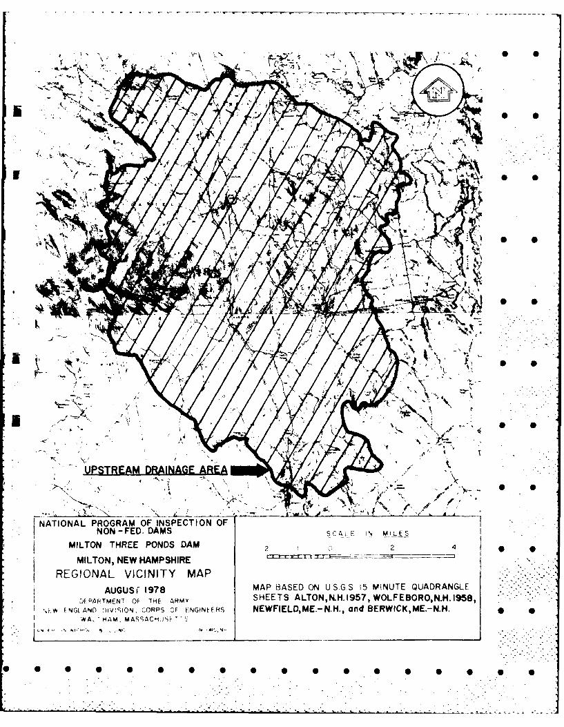
~NATIONAL PROGRAM OF INSPECTION OFNON -FED. DAMS S C ALE I N M IL E I
MILTON THREE PONDS DAM224
* MILTONNEW HAMPSHIRE
- REGIONAL VICINITY MAP* AGU~ 178MAP BASED ON US GS 15 MINUTE QUADRANGLE
DEPARTMEN7 OF THE ARMY SHEETS ALTON,N.H, 1957, WOLFE BORO, N.H. 1958,%' -Y FNGLAND 5mV!SION, CORPS OF ENGINEERS NEWFIELD, ME.- N.H., and BIERWICK,ME.-N.H.
V Al HAM, MASSACHul F T T

A 6
't.A skek -'( v\ eis o 6k;ov',,$\ OD COOG
6v-h '{J -UG-EV\&-c
e, 0
4A% U~ Gro'% LY )
395 Cqskw-\ \c-E
-h 0
kD-
* * 0 0 0 0 0 0 0 0 6 0
C-T

4-t7 L ov= v1A(l-A%( -f ouJ) P' St;.
eTO~k ep 1-7 S~ C\ c
4~~RL~ PL~4< ~CA 2- S
D- 3

k-1 SG COC<
* SS
D-

- 0
,,'?LA RLoJ - ..- " Q
. 1 " 7.7 3, ( . )0 -) o
j- +o7, 7 +P(o - 3, -- .H / 4
-7 7 L
c? I'z B')S 3z ) cl') 4 ,, 4-. 44~ 7 -42,77,7+73,0 7)4 cIs
., ,oL C SP Iv% cl ), (29F 0A C,,.,7 ,4- 4.4-0 . -i...
-- 39' 4- 7. 3, 12 e
-- ,... IS,3:-~i)Z -7) 394 (o)
NA Cu -- c ,.-
. S .cr ,h-AA,'" Q - (ocA )(Zqo,4. 4,4 .4 A') *
OU :t -,,~J .. v 94-, 734 -,J
D- 5
0 0
:..: -: .- .,:, ...,
rib~~~ zz'Th2-
(7,7 44() 0
~~2- 2-~e
31-
vp,-L,7 24-4'-74 0
- -6

Z _ Q- 4- 24A4 ( C Z4.2-
.,-4- 2
(..) 21<s, 12-(747Qc; -2, . ,
3 ~~~2 C 2
-A*p + 77)N
1 4574
149(o + -3c, +15o+I74 34" o
G~t = 0 43 2-4,4 +c 4 i 4 -3 - -0
(:if\ TE 4,' 24A4+5,4 Z 3
1 a- (o 14 7.2-)52S)4
Z 3,., F) ot II "Z. , -2 ". 1-3 2 --3 -A-30S
c -4,3e, &2 9 0 14s24,
D-7°
I 00 >
wlA Q • 0
4 _______
ek, , Q--0, --3 " "-
0 0" 0 0 0 0 =04,0 0 ,0 o, 02-40 .. . ....

-- - -' .,,---- _ A .- _ ,-- .5 -7
II
\: t " '. \ ".-0 =
-- &\6CC~ s-~~z~QWQt A•
'.- o,..- ,-,-v ; " .L .,..,,, .'o . = .I,7. :
\\o - .,%-7. \J~.z, - &"2A.,~ U7
* ~ D- I
7 - N -\."Ao±.- -, .• .. , , . . . . , • " . . .
(Z ~ ~ ~ 43Z&% (DkS35\C C
5?~ 15'% -,CF) 0 0 \'
I/:-O~ V-I)O C. QO s 45O
* v~c= fl60 Q, ~~Z3D-9~

- - - - - - - . . . . . . . . . .S
*
I
I - - . ,,
,
, . • • ,T
I - -"~ .. .. - t - -- "t - I -- ' - m.. '
.. i 2 _ . . -
- I'
q' . . . . .. , " .... 14 ', ' , 4 . . .....-
- -i .. .. ..
I • i . , , • I I I' . ,
' : ' i ''- " ]---- ' . . . ..
.. .. .,
.*.. . .
! , , t -I-_ . . .
_ _ _ _- - . _ _. _-- ._. - . -. , -•
-,
-I
, . .
• ' -.. " -- . .. .j . . ; • -.. , -. .

I, I - - - -SN -i _,_ _--d. I.. . _. ..
titl
~1D 11

.(-T- 'P~ IvL ON~i
Z0 (2, ~ q 1 Z Io 41-,F -40F,. S S
o4%C -- o 1o
Q_ _ __ _ _ W*M SlV-bV- ;6 0 c
+ -Zd -Z -7 a)l~c
m~-2e a
A, ot S)" 0
6-~ oR ?~ ±2,, ea 3
D- 12

r
-i ~ (9i -7 4-) (A.4(4-s2-'rO'3 2, (o
44! 233(o
0, 9'
D-13
* 0 S 0 0 0 0 0 0 6 0 0 0 0 0
\n dnri,,o -.\ d ls A. C o n p a vl) In c . s uth ",e .- . s No r ,, . ! , -
, J - _ __
,RE , OC 1 2 3 4 5 6 7 8 9 10 11 12 13 14 15 16 17 18 19 20 21 22 23 24 25 26 27 28 ")
4
cCA , -
14
17~~~
S0 V\~4 -~5o O O\\
* 'sr- . '"" "' :"'
('(n
,-. 0\
'N
-3A I - CS cs: -s
L 14. -
" / D-1-4€-s•

- - - -. - ----- Al
K-----~~-- .Luj - - . -
... ~. <.i -
j I -4t . 1~ ~0
I I . . .D 15

3, e
? ~ 4 4
Cc~
5' a.C C) CP , ke
c sl 3.L
= ~ ~ D- 16

- - - V
I.. ~
~ '~-9
* S
.~ =9~~'
,g~.
..=~' -' S S
.~4.
--- V.
94' ~
* S
I PX-L _
~
K' -~ *
~Y=;' ~&; ~.
*
~- .~.
~ ~ ~ .'.' **=9*~9*~~'
~ ,Q
'~ -~ ~ ~.
p..
r ~ -.
* 0 0 0 0 0 0 0 0 0 0 0 0

02
Ia.z. z
La..
cz - zW EU ~Z acc
0 Dl
I IL
0 z-
T-0 iw . 0
w cc
a~~ 0
00
(J3
i~ 0 C

FILMED
DTIC0 i
- - -