Embed Size (px)
Citation preview
UNC Steam System Design Requirements October 2003
2
1. GENERAL INFORMATION............................................................................................................................. 3
2. SYSTEM BOUNDARIES ................................................................................................................................... 3
3. SAFETY RELIEF VALVES .............................................................................................................................. 3
4. SUPPLY PRESSURES........................................................................................................................................ 4
5. CONDENSATE RETURN.................................................................................................................................. 4
6. TIE-INS TO THE CAMPUS STEAM DISTRIBUTION SYSTEM ............................................................... 4
7. UNDERGROUND STEAM AND HOT WATER DISTRIBUTION CONDUIT (NON-WALKABLE)...... 5
8. MANHOLES........................................................................................................................................................ 8
9. WALK-THROUGH TUNNELS....................................................................................................................... 13
10. CONCRETE REINFORCING STEEL ........................................................................................................... 15
11. UNDERGROUND STEAM SYSTEM ROUTING......................................................................................... 16
12. STEAM, CONDENSATE, AND HEATING HOT WATER PIPING .......................................................... 17
13. THERMAL EXPANSION ................................................................................................................................ 19
14. PIPING SUPPORTS, ANCHORS, AND GUIDES......................................................................................... 20
15. PIPING INSULATION..................................................................................................................................... 22
16. SYSTEM DRAINAGE ...................................................................................................................................... 24
17. STEAM CONDENSATE TRAPS .................................................................................................................... 24
18. VALVES............................................................................................................................................................. 25
19. CONDENSATE RETURN UNITS................................................................................................................... 26
20. CONDENSATE METERS................................................................................................................................ 26
21. STEAM METERS ............................................................................................................................................. 27
22. WELDING METHODOLOGY ....................................................................................................................... 29
23. WELDER QUALIFICATIONS ....................................................................................................................... 30
24. WELD RECORD............................................................................................................................................... 31
25. WELD EXAMINATION .................................................................................................................................. 31
26. ACCEPTANCE TESTING............................................................................................................................... 32
27. MANHOLE AND BUILDING PENETRATIONS ......................................................................................... 32
28. CLEANING – STEAM AND CONDENSATE PIPING ................................................................................ 33
29. CLEANING – HEATING HOT WATER PIPING ........................................................................................ 36
UNC Steam System Design Requirements October 2003
3
1. General Information
The University owns, maintains, and operates a steam distribution system, and condensate
return system serving the University campus and UNC Hospitals. All new facilities, and all
expansion of existing facilities, shall utilize this district steam system for space heating,
domestic hot water heating, sterilization, humidification, and other process whenever feasible.
Deviation from the use of steam as the primary heat source requires analysis showing
justification for the variance and written approval from the Director of Energy Services.
The University’s Cogeneration Facility is located at the west end of Cameron Avenue,
approximately one mile from the center of campus. Steam is provided from the central facility
via a low pressure system (LPS), a medium pressure system (MPS), and a high pressure
system (HPS). The LPS shall be utilized for all HVAC loads including humidification. The MPS
and HPS provides steam for such process equipment as sterilizes and cage washers that
require higher pressures; the MPS and HPS shall not be utilized for HVAC loads including
humidification with un-fired steam generators.
2. System Boundaries
The steam distribution system continues up to the main pressure reducing valve (PRV) station
in a building or the first isolation valve, whichever comes first. The underground design
requirements shall govern the design of any such PRV station, including materials and welding
requirements. Building PRV stations are not required. The need for a PRV station is at the
designers discretion based on down stream building equipment.
3. Safety Relief Valves
The designer may not install any safety relief valves open to the campus steam distribution
system. The distribution system already has safety valves installed and the building design
shall not affect these settings. Any safety relief valves installed by a project shall be
downstream of a building PRV and shall affect the building systems only. The campus system
safety settings are 75 psig, 95 psig, and 195 psig for the LPS, MPS, and HPS respectively. If
the building is designed without a PRV, the building equipment must be such that exposure to
these pressure limits will not cause harm, and will meet all applicable codes.
UNC Steam System Design Requirements October 2003
4
4. Supply Pressures
The Designer shall calculate and submit the maximum steam demand for each system for any
new building, addition, or renovation to the Cogeneration Facility Engineering Representative
(CFER) for determination of the adequacy of the existing steam distribution system to meet
anticipated demand. The CFER will determine if modifications to the steam distribution system
are required. The maximum steam demand shall be expressed in pounds of steam per hour for
both the total connected load and the actual expected maximum sustained demand with an
appropriate diversity factor. The CFER will provide the Designer with supply steam pressures to
be expected at the project door based upon the projected design loads.
5. Condensate Return
All building equipment which uses steam and does not contaminate the condensate shall return
the condensate to the pressurized condensate return system. An example of contaminated
condensate that should not be returned is the drainage from a cage washing unit. The designer
shall prepare a break down of returned and dumped condensate and submit a summary to the
CFER for approval.
The building steam and condensate systems should be chemically cleaned and flushed after
construction to remove all debris and as much silica as possible. The campus condensate
return system typically has an aggregate silica level of 50 ppb or less. The condensate from a
new building or renovation will not be returned to the condensate system until the silica level
drops below 200 ppb at the building pumps. Cleaning of the underground mains is covered in a
later section.
6. Tie-Ins to the Campus Steam Distribution System
Any and all tie-in’s of the project steam and condensate systems to the campus steam and
condensate systems shall be supervised by, scheduled with, and coordinated with UNC
Cogeneration Facility personnel. Connections to the campus steam system shall be performed
by the contractor under the supervision of Cogeneration Facility personnel. The Contractor
shall furnish all fittings, pipe, valves, etc., for the tie-in. The tie-in will only be made at such a
time when University operations permit an outage. This will typically be when the ambient
temperature is between 50 and 80 degrees F. The Contractor shall notify the Designer and the
UNC Steam System Design Requirements October 2003
5
CFER a minimum of fourteen (14) calendar days in advance of a requested steam outage to
perform a tie-in. The CFER has final authority on any and all scheduling for such events.
Steam will not be admitted to an installation until an account has been set up for the steam
usage and a meter has been installed. Steam shall only be admitted to an installation by
Cogeneration Systems personnel.
7. Underground Steam and Hot Water Distribution Conduit (non-walkable)
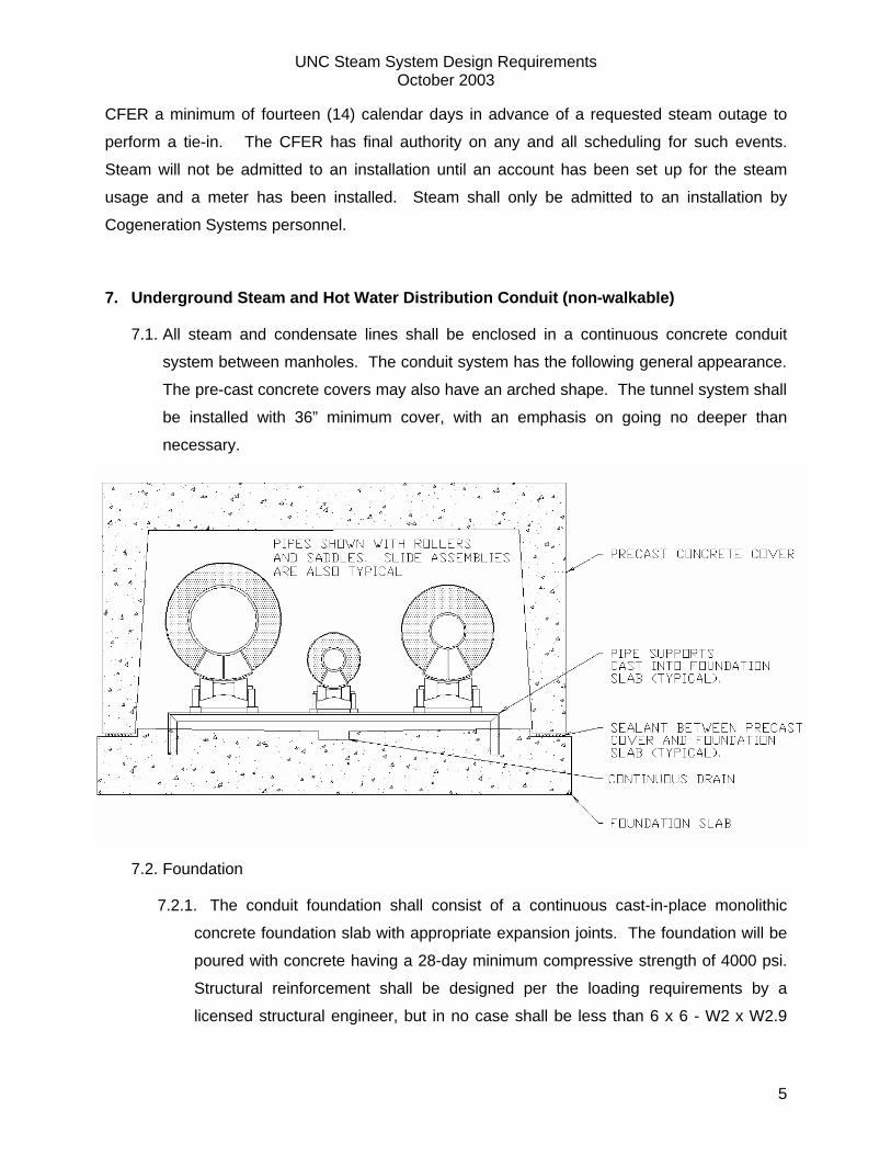
7.1. All steam and condensate lines shall be enclosed in a continuous concrete conduit
system between manholes. The conduit system has the following general appearance.
The pre-cast concrete covers may also have an arched shape. The tunnel system shall
be installed with 36” minimum cover, with an emphasis on going no deeper than
necessary.
7.2. Foundation
7.2.1. The conduit foundation shall consist of a continuous cast-in-place monolithic
concrete foundation slab with appropriate expansion joints. The foundation will be
poured with concrete having a 28-day minimum compressive strength of 4000 psi.
Structural reinforcement shall be designed per the loading requirements by a
licensed structural engineer, but in no case shall be less than 6 x 6 - W2 x W2.9
UNC Steam System Design Requirements October 2003
6
welded wire fabric (6 gage). The structural re-enforcing steel shall meet the
requirements in the steel reinforcement section of this document. The foundation
shall have a sloped floor and center drain allowing for proper drainage to the
downstream manhole of any tramp water in the conduit system. The center drain
shall have a minimum dimension of 1 ½” depth by 5 ½” width. The foundation shall
be keyed or notched on either side to accept the pre-cast covers ensuring proper
alignment, and preventing lateral motion during backfill.
7.2.2. Slab surfaces shall be screeded straight and to proper grades and pitched
uniformly to drainage points. The foundation slab and drain shall extend through
building and manhole walls unless noted on the drawings. The top surface of the
foundation slab shall be given a hand-rubbed, wood float finish. The openings to
the manhole from the conduit system shall be sealed off with 4” thick block
insulation to prevent air from drafting down the conduit system. The conduit center
drains shall not be blocked off from the manhole. Other methods of removable
insulation will be considered.
7.3. Pre-cast Covers
7.3.1. The pre-cast concrete covers in the conduit system shall not be used as a means
of piping restraint or support in any manner. At expansion loops and elbows,
conduit shall be sized to allow for expansion and contraction without damaging the
insulation, piping, or conduit structure.
7.3.2. The pre-cast covers shall be manufactured by an industrial/commercial
manufacturer who has been manufacturing the style cover selected for a minimum
of five (5) years. The manufacturer must provide a minimum of five (5) reference
projects where this cover has been used. The covers shall be cast with inside
clearance dimensions as shown on the drawings. Suppliers of pre-cast tunnel
covers must furnish calculations to the Designer to verify structural adequacy for
design loading.
7.3.3. The pre-cast covers shall be designed with interlocking ends such that the covers
joined together in a method similar to tongue-and-groove or lap-joint.
7.3.4. The concrete used in the covers shall have the minimum 28 day compressive
strength as required by the licensed structural engineer, but shall not be less than
UNC Steam System Design Requirements October 2003
7
4000 psi in any case. The conduit system shall be designed to withstand all of the
following loading conditions.
7.3.4.1. HS-20 highway loads at 2 feet of cover, and
7.3.4.2. Soil loading assuming a soil density of 100 lbm/cuft., at the installed depth
of cover, or at 10 feet of cover, whichever is greater.
7.3.5. Structural reinforcement shall be designed per the loading requirements by a
licensed structural engineer, but in no case shall be less than 6 x 6 - W2 x W2.9
welded wire fabric (6 gage). The structural re-enforcing steel shall meet the
requirements in the steel reinforcement section of this document.
7.4. Sealants
7.4.1. A waterproofing sealant shall be used at all joints between foundation slab and
pre-cast concrete covers, and at joints between adjacent pre-cast concrete cover
sections. The sealants shall be butyl resin or one part polyurethane. The
polyurethane sealants shall be equal to SikaSwell S as manufactured by SIKA.
The butyl resin sealants shall be equal to ConSeal as manufactured by Concrete
Sealants Inc.
7.4.2. The sealant shall be installed so as to provide full coverage of all concrete joint
contact surfaces per the manufacturers recommendations. Place sealant on parts
to be joined prior to final positioning of the pre-cast structures.
7.5. Waterproofing mastic
7.5.1. A heavy coat of non-asphalt, rubber/resin based mastic for underground use
shall be applied a minimum of 12 inches wide to all joints after the joint is made.
The mastic shall be equal to Sandell Special Nuflex Mastic as manufactured by
Sandell Manufacturing Co., Inc.
7.6. Waterproofing Membrane
7.6.1. A waterproofing membrane shall be installed over the entire conduit system. The
membrane shall be polyvinyl chloride. The membrane shall have a nominal
thickness of 20 mils, and have a minimum tensile strength of 2300 psi.
7.6.2. The membrane shall be wide enough to drape over the conduit structure and lap
over the foundation on both sides in one piece. The membrane shall be extended
UNC Steam System Design Requirements October 2003
8
axially along the conduit system from a large roll so as to minimize the number of
joints in the membrane.
7.6.3. The PVC membrane jacket shall be overlapped a minimum of 12 inches and
sealed with a non-asphalt resin based sealant at membrane joints to produce a
waterproof seal. The waterproofing membrane shall be adhered to the concrete
joints and to itself at overlaps. The entire conduit system shall be made waterproof.
All manufacturer’s installation recommendations shall be followed.
7.7. Waterproofing Backfill Protection
7.7.1. The waterproofing membrane shall be protected from backfill by a layer of non-
woven polypropylene. The polypropylene protective layer shall have an
approximate weight of ½ lb. per square yard. The polypropylene covering shall be
equal to Terratex non-woven geotextile No. 8 as manufactured by Webtec, Inc. At
wrap joints the materials shall overlap a minimum of 12 inches. The wrap joints
shall not be coincident with waterproofing membrane joints. All manufacture’s
installation recommendations shall be followed.
7.8. Concrete Conduit Waterproofing Alternative
7.8.1. In lieu of the above membrane and mastic system, the same waterproofing
system required for the manholes may be used for the entire conduit system, so
long as butyl resin sealants are applied to the pre-cast joints as described in item
7.4.
8. Manholes
8.1. General Structure
8.1.1. Steam manholes shall contain only steam related systems (steam, condensate,
heating hot water, and occasionally hot domestic water). Absolutely no other
utilities such as sewer, cold domestic water, electrical duct banks, chilled water,
etc. shall pass through the steam manholes, or steam conduit system.
8.1.2. Minimum manhole interior dimensions shall be L=10’ x W=10’ x H=8’. Manholes
shall be sized in excess of this as required to provide adequate and safe movement
within the finished manhole including piping insulation. Free and open access to all
UNC Steam System Design Requirements October 2003
9
operational components such as valves, drains, trap stations, etc. shall be
provided.
8.1.3. All steam and hot water manholes shall be constructed with a minimum of two
egress paths, one on each side of major obstructions such as through piping, and
generally on opposite sides of the manhole. Egress paths shall be coordinated with
the manhole ventilation design.
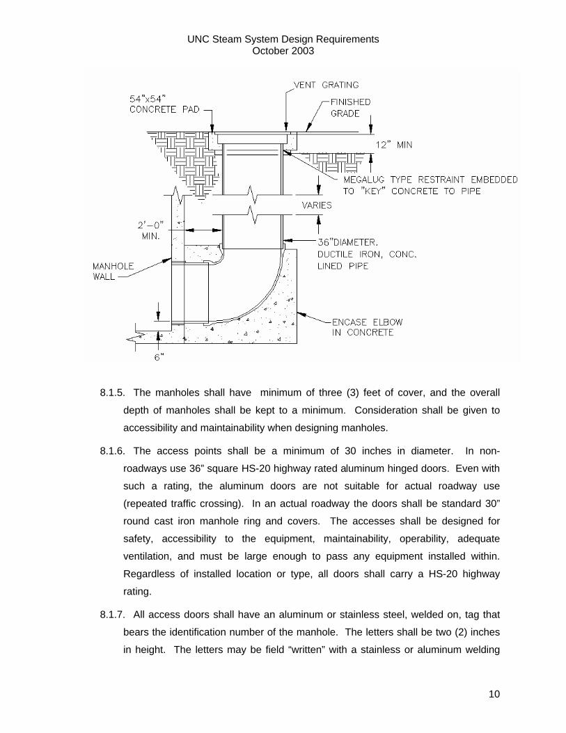
8.1.4. All steam manholes shall have a high-low natural ventilation system. The
ventilation system shall be designed to ventilate the manhole only, the conduit
system will be blocked off with insulation from drafting with the manhole. The low
vent shall be on the opposite side diagonally from the high vent if possible, or at a
minimum on the opposite parallel side. The high vent can be common with a
ladder access point. The high vent shall be positioned such that rain drops do not
drop on top of equipment and piping. Typically, the low vent is constructed of 36”
diameter ductile iron pipe adjacent to the manhole with a penetration six (6) inches
above the manhole floor. Alternately the down shaft can be cast integrally with the
manhole wall. The external ductile piping arrangement has proven to provide
superior ventilation because the exterior shaft with separation stays coolest. In all
cases the down shaft shall be exterior to the manhole, shall have a cross-sectional
area equal to or greater than a 36” diameter pipe, and shall penetrate the manhole
six (6) inches above the floor. The penetration shall be sealed full wall thickness
with non-shrink grout and shall be water proofed according to the manhole water
proofing section of this document. The landscaping around the manhole shall
prevent any surface water drainage to any manhole opening or cover. The
diagram below shows a down-shaft arrangement for the low vent.
UNC Steam System Design Requirements October 2003
10
8.1.5. The manholes shall have minimum of three (3) feet of cover, and the overall
depth of manholes shall be kept to a minimum. Consideration shall be given to
accessibility and maintainability when designing manholes.
8.1.6. The access points shall be a minimum of 30 inches in diameter. In non-
roadways use 36” square HS-20 highway rated aluminum hinged doors. Even with
such a rating, the aluminum doors are not suitable for actual roadway use
(repeated traffic crossing). In an actual roadway the doors shall be standard 30”
round cast iron manhole ring and covers. The accesses shall be designed for
safety, accessibility to the equipment, maintainability, operability, adequate
ventilation, and must be large enough to pass any equipment installed within.
Regardless of installed location or type, all doors shall carry a HS-20 highway
rating.
8.1.7. All access doors shall have an aluminum or stainless steel, welded on, tag that
bears the identification number of the manhole. The letters shall be two (2) inches
in height. The letters may be field “written” with a stainless or aluminum welding
UNC Steam System Design Requirements October 2003
11
bead in lieu of a fabricated tag. The tag shall have the form “STM-XXX” where
STM stands for steam, and XXX to be replaced with the Cogeneration Systems
manhole number.
8.1.8. Drains shall be provided in all manholes. Open drains shall be routed to the
nearest storm sewer or other suitable storm drainage location, as the purpose of
these drains is simply to remove infiltrated rain water. These drains shall have a
minimum diameter of four (4) inches. Where gravity drains cannot be installed,
sump pumps may be utilized. The sump pumps shall be Little Giant High
Temperature Sump Pumps only.
8.1.9. Whenever possible electrical switching equipment shall be located external to the
manhole in an adjacent building. In no case shall electrical equipment be located in
a non-ventilated manhole. All electrical equipment within manholes, including
junction boxes, shall be suitable for continuous full load operation in a 100%
relative humidity, 200 degrees F ambient condition.
8.1.10. All electrical conduit in manholes and in steam conduits shall be aluminum only.
The only exception is naturally ventilated (with power assist) walk-able tunnels,
where the conduit may be rigid galvanized.
8.1.11. All wiring shall be rated for a minimum of 200 degrees C and sized appropriately
for the load. Referencing table 310-19 of the 1999 National Electric Code, the
wiring shall be types, FEP, FEPB, or PFA.
8.1.12. Steps leading into manholes shall be meet OSHA standards and shall be
designed to withstand a sustained temperature of 200F.
8.1.13. Ladders entering manholes shall be constructed of stainless steel, aluminum, or
hot dipped galvanized. Fabricated ladder risers shall be 2 inch by 3/8 inch flat bar.
Fabricated ladder rungs shall be 1 inch re-bar. Smooth, round rungs will not be
accepted. The rungs shall rest in drilled holes and be welded in position. Similar
pre-manufactured stainless steel, aluminum, or hot dipped galvanized ladders or
components may be used with the owners written approval of a shop drawing. The
ladders shall be anchored to the manhole wall using stainless steel only anchor
bolts. Absolutely no individual step wall anchored type ladders will be allowed. No
carbon steel ladders will be accepted. If hot dipped material is chosen, the ladder
UNC Steam System Design Requirements October 2003
12
shall be dipped as a complete structure, not fabricated of individual pre-dipped
components.
8.1.14. Structural reinforcement shall be designed per the loading requirements by a
licensed structural engineer, but in no case shall be less than No. 4 reinforcing bar
on twelve (12) inch centers. The structural reinforcing steel shall meet the
requirements in the steel reinforcement section of this document.
8.1.15. The walls, roof, floor of the manholes shall be designed per the loading
requirements by a licensed structural engineer, but in no case shall be less than
eight (8) inches thick.
8.2. Manhole Waterproofing Materials
8.2.1. The primary water proofing barrier shall be constructed of a sprayed on, or rolled
on material that meets or exceeds all of the following requirements.
8.2.1.1. Material shall be non-toxic.
8.2.1.2. Water based, and can be applied to green, un-cured concrete.
8.2.1.3. Final cure must occur within 48 hours.
8.2.1.4. Tensile strength shall not be less than 50 psf.
8.2.1.5. Elongation without failure shall be at least 1000%.
8.2.1.6. Resilience (elongation recovery) shall be at least 95%.
8.2.1.7. Moisture vapor transmission shall be no greater than 0.02 gm/sq.ft./hr.
8.2.1.8. Shall be impenetrable to water up to 30 psig.
8.2.1.9. Shall bond to the concrete with a pull off force not less than 820 psf.
8.2.1.10. Shall remain stable and bonded up to 240 degrees F.
8.2.2. The primary waterproofing backfill protection membrane shall be a high strength
polyethylene geomembrane slip sheet, and shall meet or exceed the following
requirements.
8.2.2.1. Have a minimum thickness of 10 mils.
8.2.2.2. Have a minimum puncture resistance of 70 lbs.
8.2.2.3. Have a minimum tensile strength of 25 psi.
UNC Steam System Design Requirements October 2003
13
8.2.3. An example of these types of materials can be found at www.eproserv.com in the
EcoLine-R, EcoLine-S, and EcoShield-E line of products, as manufactured by
EPRO Waterproofing Systems.
8.3. Manhole Waterproofing Methods
8.3.1. Manhole waterproofing shall be a three step process consisting of detailing cold
joints and penetrations, applying a sprayed on / rolled on membrane to provide
overall waterproofing, and the application of a backfill protection membrane.
8.3.2. The first, or detailing step consists of applying a roll on coat of the waterproofing
compound to all cold joints and penetrations at least 3 inches on either side of the
joints and radial out from the penetrations. While still wet, an embedding fabric
shall be placed in the membrane coat. Then a second coat shall be applied to the
embedding fabric until saturated.
8.3.3. The second, or membrane application step is performed by rolling or spraying
membrane material to the manhole exterior surface in wet lifts until the material is
not less than 60 mils thick on the concrete surface. The surface shall be fully
coated, and free of gaps and cracks.
8.3.4. The third, or protection layer is a process of applying a polyethylene
geomembrane slip sheet that will protect the waterproofing membrane from backfill.
This membrane shall be applied such that the overlaps are not less than 12”, and
are sealed with a roller compressed wet layer of water proofing material.
Waterproofing seal tape shall be applied to seam overlapping 2 inches on either
side of the seam.
8.3.5. In some circumstances there is a fourth process of applying a drainage
membrane on the outside of the protection membrane to aid in ground water
drainage away from the structure. In most cases however, the manhole is
backfilled with a layer of pea-gravel which acts as the drainage mechanism.
9. Walk-Through Tunnels
9.1. Where walk through utility tunnels are applicable to the project, the walk through tunnel
containing the steam systems shall be built and waterproofed to the same standards as
defined in the manholes section of this document.
UNC Steam System Design Requirements October 2003
14
9.2. The only other utility that may share the tunnel space with the steam, condensate, and
heating hot water is UNC Chilled Water. Standards of agreement are in place for the
joint use of the tunnel for those two departments (Cogeneration Systems and Chilled
Water Systems). All other utilities such as electric duct, sewer, domestic water, storm
drainage, etc. are expressly forbidden.
9.3. All walk-through tunnels shall have a minimum of 8 feet of head clearance, and 3 feet of
clear aisle space for walking and carrying materials.
9.4. All walk-through tunnels shall be cast-in-place.
9.5. Personnel shall have a means of egress at a maximum of 300 feet in any direction (600
feet between egress points).
9.6. The walk-through tunnel system shall have natural ventilation with fan powered assist.
The fans shall be designed such that the noise emitted is not greater than 50 dbA at five
feet (measured on the surface, distance from the inlet/exhaust). The fans shall have a
hand/off/auto switch. In auto mode they shall be controlled by local thermostat.
9.7. Repairs to the piping systems will be made within the tunnel system. Provisions must
be made to provide access points where 21 foot random length piping can be lowered
into to the tunnel and moved to the necessary locations. Room to make repairs to the
piping shall be provided in the design.
9.8. Adequate lighting shall be provided through out the tunnel for egress, operation, and
maintenance.
9.9. Walk-through tunnels are the only place in the steam distribution system where
expansion joints are allowed instead of expansion loops as a means of accommodating
thermal expansion. Expansion joints used in walk-through tunnel systems shall meet
the following requirements:
9.9.1. Expansion joints shall be designed for pressure, temperature, movement, spring
rate and cycle life per Expansion Joint Manufactures Association (EJMA)
standards.
9.9.2. Expansion joints shall be weld-end, packless, constructed of externally
pressurized, double-ply (minimum) bellows.
9.9.3. The bellows material shall be 625 stainless, with carbon steel fittings.
9.9.4. Control Rings shall be constructed of cast steel, or high grade cast nickel-iron.
UNC Steam System Design Requirements October 2003
15
9.9.5. Expansion joints shall be suitable for continuous operation at 200 psig and 450F.
9.9.6. Provide joints with equalizing rings to reinforce the roots and walls of the
corrugations against internal pressure.
9.9.7. Stretching of expansion joint to correct for piping misalignment or to
accommodate available end-to-end spacing shall not be allowed.
9.9.8. Remove all shipping rods and spacers and clean inside of expansion
joints thoroughly before putting joints into service.
9.9.9. Anchors and guides shall be installed per the project documents and per
the manufactures guidelines prior to conducting piping system pressure tests or
putting joints into service.
9.9.10. Manufacturer shall be present to instruct the Contractor and witness the
installation of all expansion joints.
9.9.11. Manufacturer shall be required to review and approve, in writing, the
alignment and installation of all expansion joints prior to conducting piping system
pressure tests, or operation of system.
9.9.12. All expansion joints shall be provided with a minimum 5 year full
replacement warranty.
10. Concrete Reinforcing Steel
10.1. All re-enforcing steel used in underground steam system structures including, but
not limited to manholes, pre-cast members, tunnel slab, tunnel walls, etc. shall be epoxy
coated.
10.2. Non-coated re-enforcing steel, bar or wire mesh, will not be accepted.
10.3. The epoxy coated re-enforcing steel shall be produced by a manufacturer who
holds an Epoxy Coating Plant Certification issued by the Concrete Reinforcing Steel
Institute (CRSI).
10.4. The coated re-enforcing materials shall meet or exceed the latest versions of all
the following standards.
10.4.1. ASTM A775: Standard specification for epoxy coated steel reinforcing bars
UNC Steam System Design Requirements October 2003
16
10.4.2. ASTM A934: Standard specification for prefabricated epoxy coated steel
reinforcing bars
10.4.3. ASTM D3963: Standard specification for the fabrication and job site handling of
epoxy coated steel reinforcing bars
10.4.4. ASTM A884: Stand specification for epoxy coated steel wire and welded wire
fabric for reinforcement.
11. Underground Steam System Routing
11.1. The Contractor shall coordinate the routing of all steam and steam condensate
piping with other contractors prior to installation.
11.2. Furnish and install valves as required to allow for complete system venting and drain
down.
11.3. Grade piping and piping conduit systems not less than 1/8th inch per foot in the
direction indicated on the drawings.
11.4. Proper standoff shall be provided to protect other utilities from damage from
construction, maintenance, or operating conditions. Consideration shall be given to
potential damage to other utilities from high temperatures near steam lines.
11.5. Standoff from electrical utilities or systems shall be a minimum of 10 feet. When
adequate standoff cannot be achieved, any portion of a duct bank within ten (10) feet of
steam conduit in any direction shall be insulated with two (2) inches thick cellular glass
on the three sides closest to the steam line, until at a point not closer than ten (10) feet.
11.6. Standoff from chilled water lines shall be a minimum of ten (10) feet. When
adequate standoff between chilled water and steam lines and the chilled water lines
cannot be achieved, the chilled water lines shall be insulated with a minimum of two (2)
inches cellular glass insulation.
11.7. When steam and chilled water lines cannot be separated by ten (10) feet or more
and they must run parallel for a distance of more than 50 feet, then consideration shall
be given to a combined walk-through utility corridor, where the steam and chilled water
systems share a common tunnel system.
UNC Steam System Design Requirements October 2003
17
11.8. Piping in non-walk-able systems shall have a locating wire and warning tape installed
meeting the following requirements:
11.8.1. Direct bury a bright yellow plastic warning tape buried 12 inches above the center
of the steam conduit structure. The tape shall read “WARNING STEAM –
WARNING STEAM – WARNING STEAM”.
11.8.2. Along with the warning tape 12” above the steam conduit direct bury a locating
wire. The wire shall be equivalent to Annixter #6Q-1202-05 (bright Yellow), direct
burial 2 conductor, 12 gage stranded copper.
11.8.3. The wire shall penetrate the manholes through a one inch PVC sleeve, and be
coiled on a hook inside of the manholes. The sleeve shall be sealed with a high
temperature silicone sealant around the wire.
11.8.4. The wire shall not continue through manholes, but shall be broken inside of each
manhole. The coiled wire inside of the manholes shall be of sufficient length that it
will extend out of the manhole doors 10ft.
11.8.5. This wire will be used with Cogeneration Systems’ locating equipment to aid in
finding buried steam lines. The wire shall be clearly labeled on the hooks inside of
the manholes to say “Trace Wire”
12. Steam, Condensate, and Heating Hot Water Piping
12.1. All piping in the steam, condensate, and heating hot water piping distribution
systems shall be built in accordance with the ASME B31.1 Power Piping Code. As
dictated by the specifications, the requirements may be greater than explicitly implied in
the code.
12.2. All steam, condensate, and heating hot water piping in the distribution system shall
have welded joints. No threaded, flanged, or union joints will be permitted (except at
pumps, traps, and pressure control valves).
12.3. No steam supply pipe less than 4” nominal shall be used in the central distribution
system. No pumped condensate return line less than 2” nominal shall be used in the
distribution system. Avoid half sizes (e.g. 2½”, 3½).
12.4. Piping which is sized 2" and smaller may be socket welded or butt welded. 2 ½”
and larger shall be butt welded.
UNC Steam System Design Requirements October 2003
18
12.5. No piping smaller than 1” nominal shall be used for any service.
12.6. Butt-welded fittings shall be of a schedule matching the piping to which they are
connected and installed in accordance with ASME B16.9.
12.7. Weld-o-lets and sock-o-lets may be used in lieu of tee’s and saddles for branch
take-offs from mains 3" or larger provided that the branch take-off is two or more sizes
smaller than the main and is not larger than 4” nominal. No "stub-ins" will be permitted.
Weld-o-lets and sock-o-lets outside of these guidelines are expressly forbidden.
12.8. Use full size isolation valves throughout the steam distribution system. Do not place
reducers in distribution piping for the sole purpose of accommodating smaller isolation
valves. Size control valves as appropriate and use reducers to match.
12.9. All piping turns shall be made with standard long radius elbows. Where turns less
than 45 degrees are required, a standard long radius fitting shall be cut down and
welded in position, mitered joints (offset greater than 5 degrees) are NOT acceptable.
12.10. All piping shall bear the continuous marking of the manufacturer, ASTM grade, and
schedule number. Piping found to be defective shall be immediately removed from the
site. All piping shall be cleaned of foreign matter both inside and outside before
installation. All burrs shall be removed.
12.11. Steam piping 2 inches and smaller: Carbon steel, ASTM A53B or ASTM A106B.
Schedule extra standard (XSTD), seamless.
12.11.1. Fittings: ASTM A 105, forged steel, socket-weld, 3000# class, in accordance
with ANSI B16.11.
12.11.2. Flanges: ASTM A105 forged steel, socket weld, 300# class, in accordance
with ANSI B16.5.
12.12. Steam piping 2 ½ inches and larger: Carbon steel, ASTM A53B or ASTM
A106B. Schedule standard (STD), seamless or ERW.
12.12.1. Fittings: ASTM A234-WPB, seamless or welded, butt-weld end, schedule
standard. In accordance with B16.9
12.12.2. Flanges: ASTM A105 forged steel, weld-neck, 300# class, in accordance with
ANSI B16.5.
UNC Steam System Design Requirements October 2003
19
12.13. Condensate piping 2 inches and smaller: Carbon steel, ASTM A53B or ASTM
A106B. Schedule extra standard (XSTD), seamless.
12.13.1. Fittings: ASTM A 105, forged steel, socket-weld, 3000# class, in accordance
with ANSI B16.11.
12.13.2. Flanges: ASTM A105 forged steel, socket weld, 150# class, in accordance
with ANSI B16.5.
12.14. Condensate piping 2 ½ inches and larger: Carbon steel, ASTM A53B or ASTM
A106B. Schedule extra standard (XSTD), seamless or ERW.
12.14.1. Fittings: ASTM A234-WPB, seamless or welded, butt-weld end, schedule
standard. In accordance with B16.9
12.14.2. Flanges: ASTM A105 forged steel, weld-neck, 150# class, in accordance
with ANSI B16.5.
12.15. Heating hot water piping 2 inches and smaller: Carbon steel, ASTM A53B or
ASTM A106B. Schedule extra standard (XSTD), seamless.
12.15.1. Fittings: ASTM A 105, forged steel, socket-weld, 3000# class, in accordance
with ANSI B16.11.
12.15.2. Flanges: ASTM A105 forged steel, socket weld, 150# class, in accordance
with ANSI B16.5.
12.16. Heating hot water piping 2 ½ inches and larger: Carbon steel, ASTM A53B or
ASTM A106B. Schedule extra standard (XSTD), seamless or ERW.
12.16.1. Fittings: ASTM A234-WPB, seamless or welded, butt-weld end, schedule
standard. In accordance with B16.9
12.16.2. Flanges: ASTM A105 forged steel, weld-neck, 150# class, in accordance with
ANSI B16.5.
13. Thermal Expansion
13.1. For the purposes of calculating piping stresses, anchor loading, etc. the designer
shall consider the maximum working pressure of the steam and condensate piping to be
200 psig @ 450F. Every component of the steam and condensate system from
anchors, to expansion loops, expansion joints, fittings, valves, trap bodies, etc. shall be
capable of continuous operation at these conditions. (NOTE: Trap orifices shall be
UNC Steam System Design Requirements October 2003
20
selected based on the operating condition, not the design condition. Orifice selection is
covered in the “Steam Condensate Traps” section of this document).
13.2. For heating hot water systems the maximum working pressure shall be
considered 200 psig @ 250F.
13.3. Expansion loops, Z’s, and L’s are the required method for incorporating piping
flexibility. Expansion joints will only be considered in walk-through tunnel systems.
14. Piping Supports, Anchors, and Guides
14.1. All piping shall be supported with devices which permit the pipe to expand
thermally without wear to the pipe. Slide type supports, or roller type supports may be
used. When rollers are used, piping saddles matching or exceeding the insulation
depth shall be used. When slides are used, a Teflon slide surface shall be integral to
the slide design. All means of pipe supports shall be secured in position. Anchor and
guide supports shall be cast into the base slab when it is poured. Supports providing
only vertical support may be secured by stainless anchor bolts rather than cast in place.
14.2. All supporting and restraining devices must be selected as part of the system
stress analysis. The devices shall be suitable to sustain the static and dynamic loads of
the system as defined in the ASME B31.1 Power Piping Code.
14.3. No anchoring systems which use insulation as a means of piping restraint or
support shall be allowed. Anchors shall be welded to piping. Saddles shall be tack
welded to the piping. Guides structure shall be welded to the piping. All wear shall
occur between saddles and roller, or between guides and substrate, with no wear at the
piping.
14.4. All structural embedments and anchor bolts penetrating the concrete structures
shall be stainless steel. An example would be a simple channel support where a
horizontal channel is welded to two 3” pipes embedded into the concrete to create a flat
support structure for an anchor, guide, support, etc. The pipes embedded in the
concrete would be 304L stainless steel. The channel iron cross member would be
carbon steel. Only the material penetrating the concrete needs to be stainless. In the
case of 304L stainless pipe welded to carbon steel channel, SS309 filler material would
UNC Steam System Design Requirements October 2003
21
be used to make the dissimilar metal weld. Carbon steel shall not be used within 2
inches of the floor of manholes or pipe conduits.
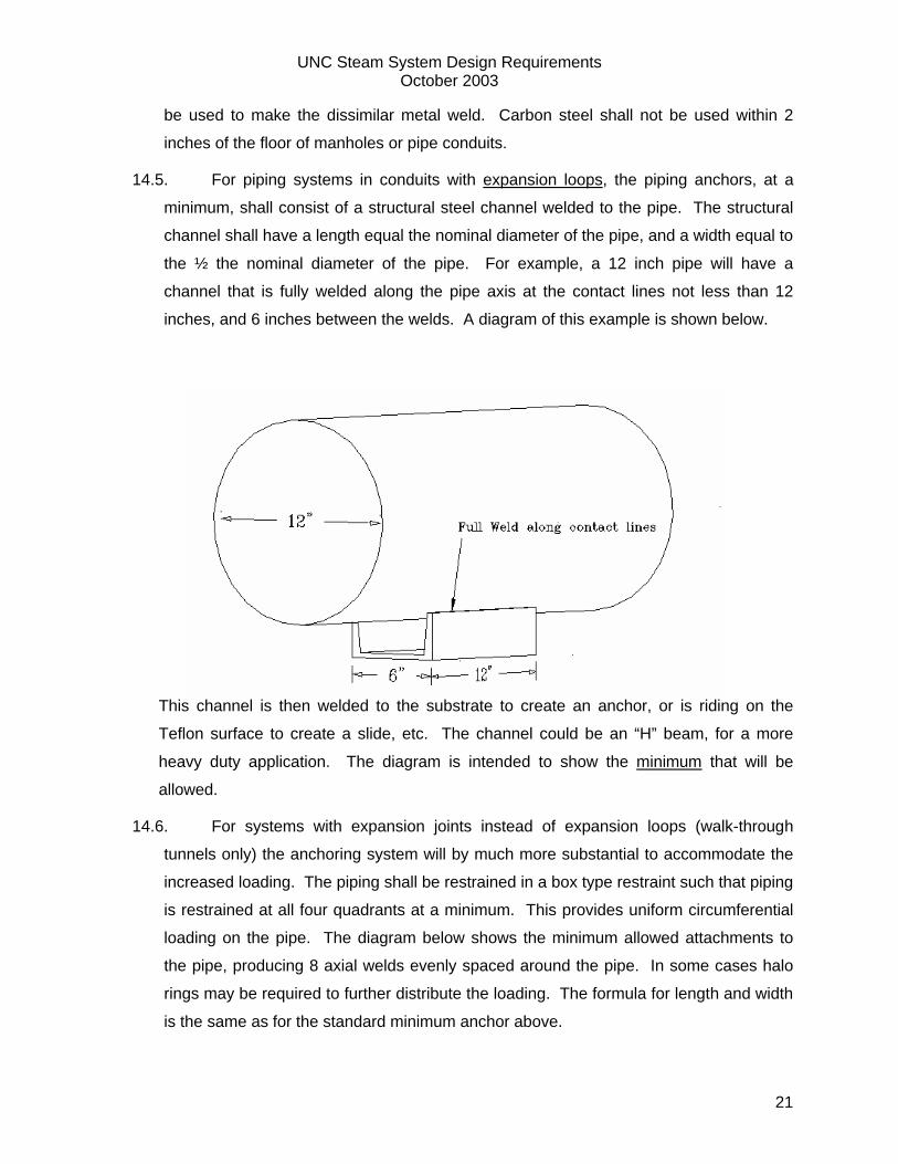
14.5. For piping systems in conduits with expansion loops, the piping anchors, at a
minimum, shall consist of a structural steel channel welded to the pipe. The structural
channel shall have a length equal the nominal diameter of the pipe, and a width equal to
the ½ the nominal diameter of the pipe. For example, a 12 inch pipe will have a
channel that is fully welded along the pipe axis at the contact lines not less than 12
inches, and 6 inches between the welds. A diagram of this example is shown below.
This channel is then welded to the substrate to create an anchor, or is riding on the
Teflon surface to create a slide, etc. The channel could be an “H” beam, for a more
heavy duty application. The diagram is intended to show the minimum that will be
allowed.
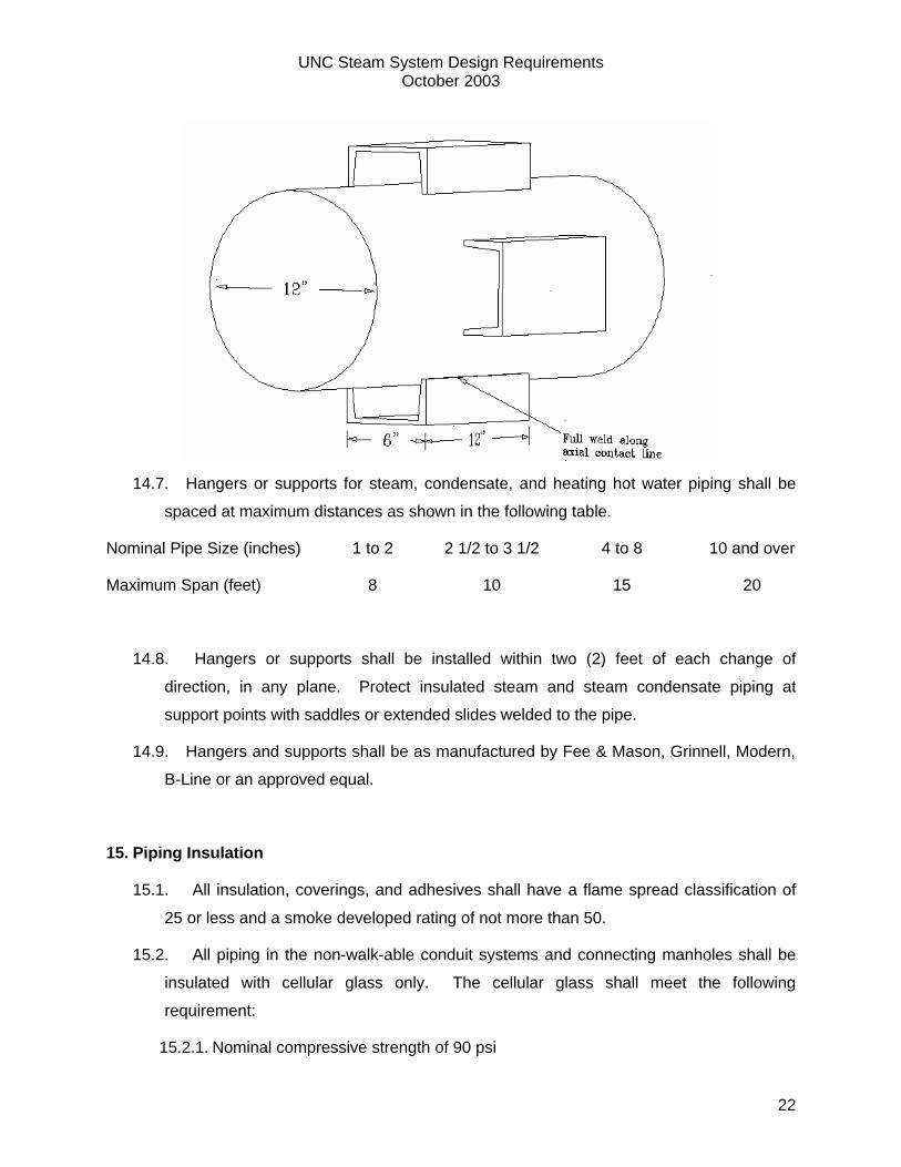
14.6. For systems with expansion joints instead of expansion loops (walk-through
tunnels only) the anchoring system will by much more substantial to accommodate the
increased loading. The piping shall be restrained in a box type restraint such that piping
is restrained at all four quadrants at a minimum. This provides uniform circumferential
loading on the pipe. The diagram below shows the minimum allowed attachments to
the pipe, producing 8 axial welds evenly spaced around the pipe. In some cases halo
rings may be required to further distribute the loading. The formula for length and width
is the same as for the standard minimum anchor above.
UNC Steam System Design Requirements October 2003
22
14.7. Hangers or supports for steam, condensate, and heating hot water piping shall be
spaced at maximum distances as shown in the following table.
Nominal Pipe Size (inches) 1 to 2 2 1/2 to 3 1/2 4 to 8 10 and over
Maximum Span (feet) 8 10 15 20
14.8. Hangers or supports shall be installed within two (2) feet of each change of
direction, in any plane. Protect insulated steam and steam condensate piping at
support points with saddles or extended slides welded to the pipe.
14.9. Hangers and supports shall be as manufactured by Fee & Mason, Grinnell, Modern,
B-Line or an approved equal.
15. Piping Insulation
15.1. All insulation, coverings, and adhesives shall have a flame spread classification of
25 or less and a smoke developed rating of not more than 50.
15.2. All piping in the non-walk-able conduit systems and connecting manholes shall be
insulated with cellular glass only. The cellular glass shall meet the following
requirement:
15.2.1. Nominal compressive strength of 90 psi
UNC Steam System Design Requirements October 2003
23
15.2.2. Water vapor permeability of 0%
15.2.3. Thermal conductivity not greater than 0.29 Btu-in/hr-ft2-oF
15.3. Distribution piping in building mechanical rooms, and in completely ventilated,
accessible, full walk-through tunnels can be insulated with 6 lbm/cu-ft, high density
fiberglass as an alternate ( this does not include normal manholes). The transition from
cellular glass to fiberglass shall happen within the approved areas, and shall be clearly
indicated on the drawings. Any fiberglass insulation that gets wet during construction
will be removed and replaced at the contractors expense.
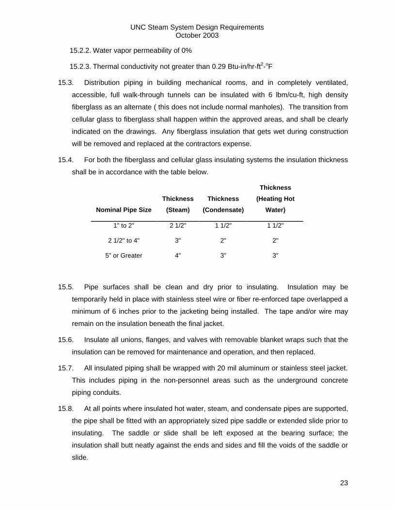
15.4. For both the fiberglass and cellular glass insulating systems the insulation thickness
shall be in accordance with the table below.
Nominal Pipe Size
Thickness
(Steam)
Thickness
(Condensate)
Thickness
(Heating Hot
Water)
1" to 2" 2 1/2" 1 1/2" 1 1/2"
2 1/2" to 4" 3" 2" 2"
5" or Greater 4" 3" 3"
15.5. Pipe surfaces shall be clean and dry prior to insulating. Insulation may be
temporarily held in place with stainless steel wire or fiber re-enforced tape overlapped a
minimum of 6 inches prior to the jacketing being installed. The tape and/or wire may
remain on the insulation beneath the final jacket.
15.6. Insulate all unions, flanges, and valves with removable blanket wraps such that the
insulation can be removed for maintenance and operation, and then replaced.
15.7. All insulated piping shall be wrapped with 20 mil aluminum or stainless steel jacket.
This includes piping in the non-personnel areas such as the underground concrete
piping conduits.
15.8. At all points where insulated hot water, steam, and condensate pipes are supported,
the pipe shall be fitted with an appropriately sized pipe saddle or extended slide prior to
insulating. The saddle or slide shall be left exposed at the bearing surface; the
insulation shall butt neatly against the ends and sides and fill the voids of the saddle or
slide.
UNC Steam System Design Requirements October 2003
24
15.9. Insulation shall be extended continuously through pipe sleeves.
15.10. Only non-asbestos insulation materials shall be used for any insulating medium.
16. System Drainage
16.1. The steam distribution system shall have a drip leg and trap station at every low
point in the system. The condensate return system, and hot water systems shall have
drains at every low point, and shall have vents at every high point.
16.2. The steam distribution system shall have a drip and trap station at least every 450
lineal feet of piping run.
16.3. For every main line isolation valve in the steam system. Closing the valve creates a
dead leg in the system with a high point and a low point. The side of the valve creating
a low point (side that holds water) shall have a drip leg and trap station. The side
draining away from the valve shall have a 2 inch full port manual drain. For valves with
supply pressure on both sides, and where the valve is the low point relative to both
sides, a trap station shall be installed on both sides of the valve.
16.4. The drip legs shall be full size through 8 inch piping and shall be at least ½ the size
of the main line for lines larger than 8 inch. (i.e. 10” drip leg on a 20” main). The legs
shall be of sufficient depth to hold temporary condensate surges until the traps can
remove the condensate.
16.5. The traps shall be located sufficiently above the bottom of the leg so as to prevent
dirt from entering the trap line.
16.6. All blow down drain and vent valves shall be 2 inch 600# class, full port, socket
welded gate valves. The drains shall have welded construction with the end of each
drain terminating in a Sch. 80 threaded pipe nipple. The entrance end of the nipple shall
have its threads cut off, prepped, and welded in position. A threaded cap shall be
placed on the exit end of the nipple.
17. Steam Condensate Traps
17.1. All steam traps installed in the campus distribution system shall be of the inverted
bucket type.
UNC Steam System Design Requirements October 2003
25
17.2. All steam traps in the distribution system will be standardized to one trap. The
Armstrong inverted bucket model 813 with a 1” connection size. For the campus LPS
system the orifice size shall be 5/16”. For the campus MPS system the orifice size shall
be 1/4”. For the campus HPS system the orifice size shall be 7/32”. These orifices are
matched to the model 813 trap for the pressure differential in the systems.
17.3. The model 813 trap is 12 inches tall, and must be positioned below the steam line to
effect proper drainage. This shall be taken into account in the design of the system.
17.4. Traps shall be installed with isolation valves, unions, check valves, and strainer.
Blow down valves shall be provided on the strainers. Trap discharge shall be routed to
an atmospherically vented flash tank, and then to a condensate return pump set,
preferably in the closest building mechanical room. Injecting trap discharge into a
condensate return main is not permitted.
18. Valves
18.1. All valves shall be brand new, un-refurbished, first quality.
18.2. All isolation valves 2 ½” and above in the steam distribution system, up to and
including the first valve inside of a building, shall be full port, butt-weld-end 300# class,
gate valves suitable for operation at 450F. No brass or copper shall be permitted.
18.3. All isolation valves 2” and below shall be full port, socket weld 600# class, gate
valves suitable for operation at 450F. No brass or copper shall be permitted.
18.4. Where possible, a project shall provide valves from one manufacturer in the
underground steam, condensate, and hot water systems.
18.5. The acceptable isolation valve manufactures are (in no order):
18.5.1. Crane
18.5.2. Edwards
18.5.3. Jenkins
18.5.4. Lunkenheimer
18.5.5. Milwaukee
18.5.6. Powell
UNC Steam System Design Requirements October 2003
26
18.5.7. Walworth
18.5.8. Williams
19. Condensate Return Units
19.1. All building and trap condensate shall be routed to an atmospherically vented flash
tank prior to entering the condensate receiver.
19.2. Condensate return pump/tank sets shall be duplex type provided with a float-
operated mechanical alternating switch, sight glass, and check and gate valves on each
pump discharge line.
19.3. The pump set must utilize “off the shelf” electric motors that can be purchased from
any typical motor supplier. The motors cannot be custom to the design of the pump or
manufacturer.
19.4. The pump set must be rated for continuous operation while pumping 212oF water at
a back pressure 75 psig.
19.5. The pump set shall be provided with integral back pressure regulators for the pumps.
19.6. The pump set must come standard with a tank that is elevated 2 feet above the
pumps as a pre-manufactured set.
19.7. The unit shall be installed such that the motors are not less than one foot above floor
level, with two feet preferred in manholes and pits.
19.8. The pump set should be as manufactured by SHIPCO Pumps, type PEC (Propeller
Elevated Condensate) or equivalent.
20. Condensate Meters
20.1. The contractor shall provide and install a condensate meter for every building to
measure the condensate returned from the building.
20.2. Condensate meters shall be Niagara hot water meters of type MTX or WPX as
sizing dictates, with local mechanical totalizers and integrated dry contact closures. Dry
contacts should not be confused with a pulse output, the contacts provide momentary
contact closure once per block unit of total. It does not provide rate as a pulse
UNC Steam System Design Requirements October 2003
27
transmitter does. The contacts shall be left disconnected, they will be connected at a
later date by Cogeneration Systems. The engineering specifications and cut sheets can
be found at www.niagarameters.com.
20.3. The meter shall be sized to handle the full pumping rate of the condensate return
unit, with both pumps running in a high-high tank level condition.
20.4. Strainers shall be provided upstream of each meter with mesh sizing per the
meter manufacturer’s recommendation.
20.5. An isolation gate valve shall be provided on the discharge side of the meter,
isolating the meter from the campus condensate system.
20.6. A check valve shall be provided in the meter discharge line downstream of the
meter and installed according to the manufacturer’s recommendations.
20.7. The meter shall be installed in a horizontal pipe with the dial facing up, and shall
be easily accessible. The reader shall not have to climb a ladder, or enter a pit to read
the meter.
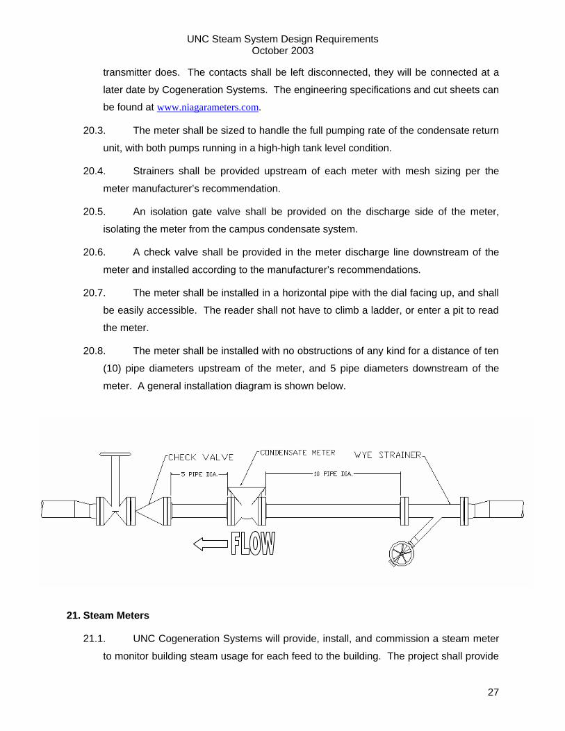
20.8. The meter shall be installed with no obstructions of any kind for a distance of ten
(10) pipe diameters upstream of the meter, and 5 pipe diameters downstream of the
meter. A general installation diagram is shown below.
21. Steam Meters
21.1. UNC Cogeneration Systems will provide, install, and commission a steam meter
to monitor building steam usage for each feed to the building. The project shall provide
UNC Steam System Design Requirements October 2003
28
a monetary reserve in the amount of $7,500 payable to UNC Cogeneration Systems to
cover the cost of the equipment and installation. If the building has dual feeds (high and
low pressure) the reserve shall be $10,000.
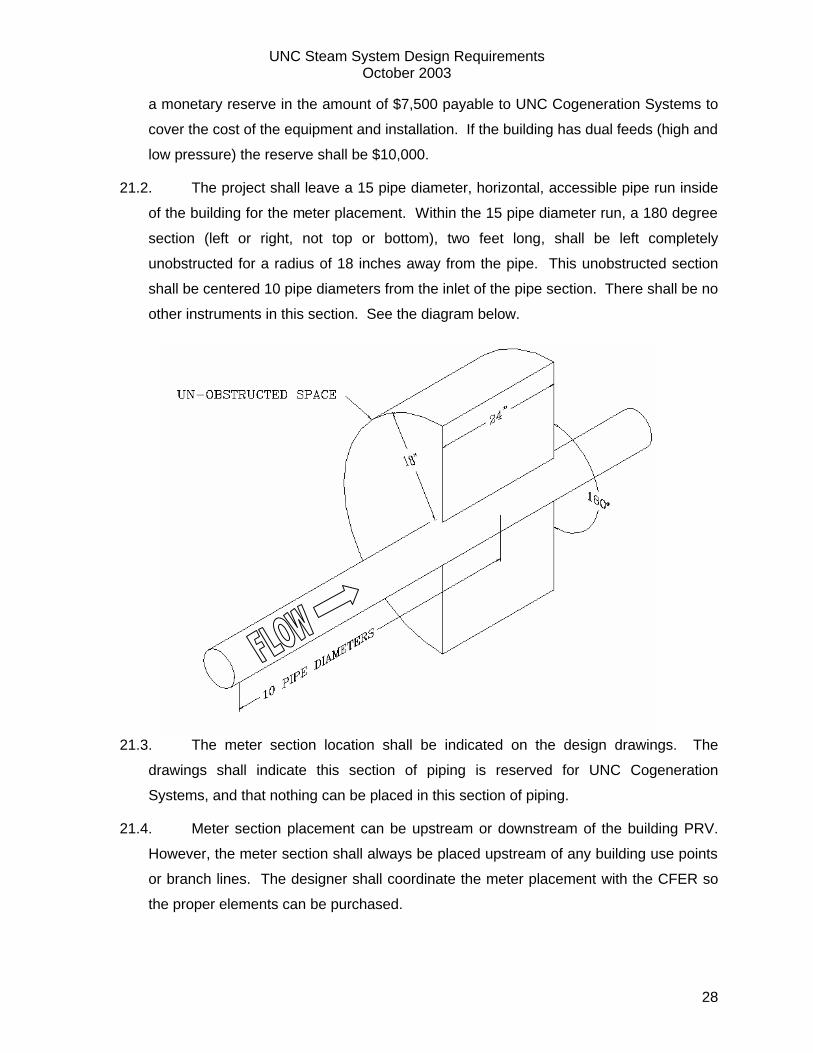
21.2. The project shall leave a 15 pipe diameter, horizontal, accessible pipe run inside
of the building for the meter placement. Within the 15 pipe diameter run, a 180 degree
section (left or right, not top or bottom), two feet long, shall be left completely
unobstructed for a radius of 18 inches away from the pipe. This unobstructed section
shall be centered 10 pipe diameters from the inlet of the pipe section. There shall be no
other instruments in this section. See the diagram below.
21.3. The meter section location shall be indicated on the design drawings. The
drawings shall indicate this section of piping is reserved for UNC Cogeneration
Systems, and that nothing can be placed in this section of piping.
21.4. Meter section placement can be upstream or downstream of the building PRV.
However, the meter section shall always be placed upstream of any building use points
or branch lines. The designer shall coordinate the meter placement with the CFER so
the proper elements can be purchased.
UNC Steam System Design Requirements October 2003
29
21.5. The electronics for the meter will be housed in a 20x20x10 inch deep control
enclosure. UNC Cogeneration Systems will provide this enclosure, and turn it over to
the contractor for mounting so that he has a termination point for the required wiring.
21.6. The enclosure shall be mounted such that the bottom face is 56” above finished
floor elevation.
21.7. The enclosure shall be mounted in an area as close to the meter piping section
as feasible, but where the ambient air temperature will not exceed 100oF. The designer
shall show the appropriate location on the contract drawings, and the contractor shall
confirm with the CFER when taking delivery of the enclosure.
21.8. The project shall provide a dedicated 115V circuit for the steam meter with
conduit and wiring brought to the meter control enclosure. The power conduit shall not
be less than ¾” and shall enter the enclosure at the top right corner. This circuit shall
have a dedicated 15 amp breaker, and nothing else shall connect to this circuit.
21.9. The project shall provide a data connection running from the building main data
switch to the meter control enclosure. The data conduit shall not be less than ¾” and
shall enter the enclosure at the top left corner. The data cable shall be connected to the
Steam V-LAN at the building switch, and be labeled as such. The data cable shall
terminate in a surface mount RJ-45 receptacle in the enclosure. The data connection
shall meet UNC Telecomm standards for the building.
22. Welding Methodology
22.1.1. Welding shall be done using only the following processes:
22.1.1.1. Shielded Metal Arc Welding (SMAW), also known as "stick" welding
22.1.1.2. Gas Tungsten Arc Welding (GTAW), also known as TIG and Heliarc
welding
22.1.1.3. Metal Inert Gas Welding (MIG)
22.1.1.4. Submerged Arc Welding (SAW)
22.1.2. For stainless steel piping, root passes must be applied by the GTAW
process with argon gas purge, only.
UNC Steam System Design Requirements October 2003
30
22.1.3. Fabrication, installation, inspection, examination and testing shall be in
accordance with B31.1, and further as the project documents require.
22.1.4. Backing rings (chill rings) or consumable inserts are not allowed.
22.1.5. All completed welds shall be wire brushed a minimum of 2 inches on either
side and coated with rust inhibitive primer prior to being insulated.
23. Welder Qualifications
23.1. All welding shall be performed by qualified welders who are regularly engaged in
welding of piping systems. The welders’ certifications shall cover the exact
procedure(s) to be used on the project piping systems.
23.2. All Welding Procedure Specifications (WPS’s) and their supporting Procedure
Qualification Records (PQR’s) shall be submitted to Engineer of Record for review and
approval prior to performing any welding. These documents shall meet requirements of
ASME B31.1. Submit a copy of the Manufacturer's Record of Welder or Welding
Operator Qualification Tests as required by Section IX of ASME Boiler and Pressure
Vessel Code for all welding procedures to be performed by the welding operator.
23.3. The qualifying test segment shall be 2" nominal pipe size with wall thickness within
range of WPS for each pipe material specified in this Section. Test position shall be
arranged in "6G position".
23.4. Welders shall be qualified in accordance with ASME B31.1. The welding
qualification tests shall have an independent witness. The witness shall be a
representative of independent testing laboratory, Authorized (Code) Inspector, or
consultant approved by National Certified Pipe Welding Bureau.
23.5. Welder qualifications must be current. If qualification test is more than 6 months
old, provide record of welding continuity for each welder. Record of welding continuity
shall include, at a minimum, the following:
23.5.1. Welder's employer name and address
23.5.2. Date Welder Qualification Test was passed
23.5.3. Dates of work performed and type indicating welding continuity.
UNC Steam System Design Requirements October 2003
31
23.5.4. If the continuity record is not satisfactory to the Engineer or the owner, the
welder shall re-qualify before performing any work.
24. Weld record
24.1. For all pipe welding the contractors shall submit to the Engineer for approval an
administrative procedure for recording, locating, monitoring and maintaining the quality
of all welds to be performed on the project. This quality control document record shall
include but not be limited to:
24.2. Drawings and schedules identifying location of each weld by individual number,
identification of welder who performed each weld by individual welder's name, stamp
number, date, and WPS used.
24.3. Once the procedure is approved, the Contractor shall carry out the procedure and
the Engineer shall review the weld record documents monthly.
24.4. A finalized copy of the weld record shall be turned over to the CFER at the
completion of the project.
25. Weld Examination
25.1. 100% of the welds in the steam, condensate, and heating hot water distribution
system will be inspected and tested by non-destructive examination.
25.2. All tests shall be performed by an AWS-CWI (American Welding Society Certified
Welding Inspector). The firm providing these services shall be agreed upon by the
mechanical engineer and the owner.
25.3. All butt welds shall be tested by means of radiography. The criterion for pass/fail of
this test will be as defined in the latest edition of the ASME B31.1 Power Piping code.
25.4. All socket weld connections shall be tested by means of dye penetrate or magnetic
particle analysis. The criterion for pass/fail of this test will be as defined in the latest
edition of the ASME B31.1 Power Piping code.
25.5. In the rare occurrence where radiography cannot be used to test a weld due to site
restrictions the weld may be visually inspected by an AWS certified welding inspector
provided that all the following conditions are met.
UNC Steam System Design Requirements October 2003
32
25.5.1. The CFER and design engineer must agree that a radiographic test cannot be
reasonably achieved.
25.5.2. The pipe joint fit up must be inspected prior to welding by an AWS-CWI.
25.5.3. All welding passes must be inspected by an AWS-CWI including the root pass,
hot pass, and all fill and cover passes.
25.5.4. If any of these steps are bypassed, and radiography cannot be utilized to verify
the joint integrity, then the joint will be rejected outright and it will be replaced at the
contractors expense. The replacement joint will be subject to the same testing
requirements.
25.6. All initial testing will be funded by the owner through the project testing funds.
25.7. All repairs, and re-examination of repaired welds will be at the contractors expense
26. Acceptance Testing
All steam and steam condensate piping systems shall be tested at a hydrostatic pressure of 300
psig. The test shall be for a period not less than four hours with no pressure drop and shall be
performed in the presence of the Designer. After any leaks are found and corrected the test
shall be repeated.
27. Manhole and Building Penetrations
27.1. Where feasible the concrete steam conduit shall penetrate the manhole wall or
building wall through the wall thickness and end flush with the inside wall face.
27.2. The wall shall either be integrally cast around the conduit to create a true cold joint,
or if the conduit is placed through a pre-cut opening, the opening shall be “walled up”
with masonry, concrete, and non-shrink grout as needed to provide a seal around the
conduit.
27.3. The air space between the piping and conduit walls shall be blocked insulation to
prevent drafting of the conduit system into the manholes or buildings.
27.4. Where lines must penetrate through walls, floors, and ceilings where there is no
conduit, sleeves must be furnished and installed. The sleeves shall be schedule 40
black steel pipe and large enough to provide clear design movement of the pipe without
UNC Steam System Design Requirements October 2003
33
damaging the piping insulation. Sleeves through walls and ceilings shall be flush,
sleeves through floors shall extend 1" above the finished floor. Sleeves in the floor and
in exterior walls shall be sealed with "Chase Foam" by Chase Foam Technologies, or
equivalent. The contractor shall be responsible for the accurate placement of all
sleeves.
28. Cleaning – Steam and Condensate Piping
28.1. All steam and condensate piping in the distribution system shall be cleaned prior to
its connection to the University’s district energy system.
28.2. The steam and condensate piping shall be cleaned by means of steam blow only.
28.3. The contractor shall procure the services of qualified company to perform the steam
blow(s) or may elect to have the University self perform the work.
28.4. The required steam blows may be completed by the University’s Cogeneration
Systems Group or by a qualified industrial cleaning service contractor meeting the
requirements of this specification. The Contractor can contact the CFER at UNC
Cogeneration Systems for details and pricing related to the steam blow. If the
Contractor wishes to use an external company rather than proceeding with the
University, then it is highly recommended that he request “an approved equal” status for
the cleaning contractor prior to the bid.
28.5. All in-line instruments and devices shall be removed prior flushing and steam
blowing, and replaced with spool pieces if necessary. After the completion of the
cleaning, the Contractor shall reinstall all instruments.
28.6. All permanent piping shall have passed its hydrostatic test and be flushed with
water to remove loose debris prior to any steam blow.
28.7. All steam and condensate lines shall be blown three separate times with cool down
periods between each blow to cause thermal cycling of the piping. This is to facilitate
the release of welding slag and other bonded debris.
28.8. During the final blow for each pipe, the process shall generate not less than 250
feet per second of steam flow velocity in all sections of the permanent piping, and
maintain this velocity for period not less than one hour. The blow shall continue until
UNC Steam System Design Requirements October 2003
34
the piping is deemed clean enough to connect to the University’s district energy system
by the CFER.
28.9. The steam blow shall be witnessed by the CFER and the mechanical design
engineer of record, or their designated representatives.
28.10. The steam blow shall not be conducted when the ambient air temperature is less
than 50 degrees F or greater than 80 degrees F. Any such event shall be scheduled
with Cogeneration Systems personnel. The scheduling of such events will be
dependent on campus load, and steam availability, and outages required.
Cogeneration Systems has final authority on the scheduling of all such events.
28.11. The steam blow shall minimize stress to the system components caused by
excessive temperature and/or pressure changes.
28.12. The arrangement of the temporary piping shall be designed in accordance with
ASME B31.1. The piping arrangement and steam blow shall not cause the stress levels
in any permanent or temporary piping component to exceed the allowable levels listed
in ASME B31.1.
28.13. Any low points created as a result of the temporary piping arrangement shall have
manual drains installed for proper drainage during the blow. If the drains are installed in
permanent piping they shall be installed in accordance with the permanent piping
standards for this project, and shall remain. If they are temporary to be removed after
the steam blow, they may be of suitable temporary construction, such as threaded
brass or bronze valves.
28.14. The exhaust end of the line(s) being blown shall be muffled and/or quenched as
required to maintain 85 dBA or less at a distance of 50 feet from the steam discharge
point.
28.15. Steam discharge shall not produce shock waves or air born particulate which could
settle on parked cars, people, buildings, etc. This includes small material which may
soil clothing, buildings, cars, etc.
28.16. Modifications to any permanent fixtures or systems to accommodate the steam blow
shall be repaired and or replaced at the completion of the event to the satisfaction of the
University and the designer of record.
UNC Steam System Design Requirements October 2003
35
28.17. The contractor shall provide barricades, warning tapes, and signage as necessary
to secure the immediate area during the steam blow.
28.18. The contractor and his cleaning sub-contractor shall provide all necessary
temporary piping, valves, mufflers, etc. needed to accomplish the steam blow(s) safely
and within the guidelines of this specification.
28.19. If a cleaning contractor other than the University is selected, that contractor shall
submit the following for approval by the designer and the CFER prior to any cleaning
equipment coming onsite:
28.19.1. Only firms experienced in performing steam blows in noise sensitive areas for
similar projects shall be considered. The proposed service company shall submit a
list of projects where they have performed steam blows in noise sensitive areas for
projects of similar size and flow requirements to this project. The list shall include
five projects where distribution lines have been blow within the past ten years. This
list shall include a brief description of the scope of work for each project, including
the size of the piping blown, the name and location of the facility generating the
steam, and a contact name and telephone number for each facility. For each
project provide a brief description of the noise sensitive issues, what was done to
satisfy the requirements, and the general results of those actions. Failure to
provide qualifications in this format will result in rejection of the proposed service
company.
28.19.2. Steam blow procedure indicating pressure required, quantity of flow, and
duration.
28.19.3. An description of how much temporary piping is going to be installed, and
what size.
28.19.4. Acceptance criterion for each blow.
28.19.5. Process flow diagram showing steam flow direction through the temporary and
permanent piping.
28.19.6. Layout drawings depicting the setup of the temporary equipment and its
connection to the piping to be cleaned.
28.19.7. Maximum noise levels that will be emitted during the cleaning process.
UNC Steam System Design Requirements October 2003
36
28.19.8. MSDS of all chemicals used, if any. Include a description of the proper
disposal method for any waste.
29. Cleaning – Heating Hot Water Piping
29.1. All heating hot water piping in the distribution system shall be cleaned by means
of chemical flush and filter.
29.2. The chemical flush shall be performed by a qualified contractor who has
performed this type of work for industrial systems continuously for a period not less than
five (5) years.
29.3. The cleaning contractor shall provide in writing the acceptance criterion for the
cleaning process per the cleaning contractors standards as part of the submittal
process.
29.4. The submittals shall include MSDS of all chemicals used, including a description
of the proper disposal method for any waste.
29.5. Temporary filters shall be used during the flush to remove debris loosened by the
cleaning process.
29.6. The supply and return lines shall be tied together on each end and the cleaning
solution shall be circulated by temporary cleaning pump until filter checks show the fluid
is clean, or twenty-four (24) hours, whichever is longer.
29.7. All instrumentation, and any system component not compatible with the cleaning
process shall be removed before the cleaning agent is applied.
29.8. The system shall be flushed and circulated with clean water after the cleaning
process until the system is free of the cleaning solution, and is in a neutral pH state.
29.9. Proper disposal of any contaminated fluids shall be the responsibility of the
contractor.