Embed Size (px)
Citation preview
BBR
VT
CO
NA
CM
MU
nbon
ded
Post
-tens
ioni
ng S
yste
m
European Technical AssessmentETA – 06/0165
0432
ETA-06/0165BBR VT CONA CMM
Unbonded Post-tensioning System with 01, 02 and 04 Strands
BBR VT International LtdRingstrasse 2, 8603 Schwerzenbach (Switzerland)
www.bbrnetwork.com
0432-CPD-11 9181-1.2/111
Responsible BBR PT Specialist Company
The delivery note accompanying components of the BBR VT CONA CMM Post-tensioning System will contain the CE marking.
Assembly and installation of BBR VT CONA CMM tendons must only be carried out by qualified BBR PT Specialist Companies. Find the local BBR PT Specialist Company by visiting the BBR Network website www.bbrnetwork.com.
European Organisation for Technical ApprovalsEuropäische Organisation für Technische ZulassungenOrganisation Européenne pour l’Agrément technique
Guideline for European Technical Approval of Post-tensioning Kits for Prestressing of Structures
Requirements for the installation of post-tensioning kits for prestressing of structures and qualification of the specialist company and its personnel
BBR E-Trace is the trading and quality assurance platform of the BBR Network linking the Holder of Approval, BBR VT International Ltd, BBR PT Specialist Companies and the BBR Manufacturing Plant. Along with the established BBR Factory Production Control, BBR E-Trace provides effective supply chain management including installation, delivery notes and highest quality standards, as well as full traceability of components.
Year
PT Specialist Company
Company
ww
w.bbrnetwork.com
ETAG 013
CWA 14646
S P E C I ME N
Designated according to Article 29 of
Regulation (EU) No 305/2011 www.eota.eu
Member of
Schenkenstrasse 4 1010 Vienna ι Austria
T +43 1 533 65 50 F +43 1 533 64 23
www.oib.or.at ι [email protected]
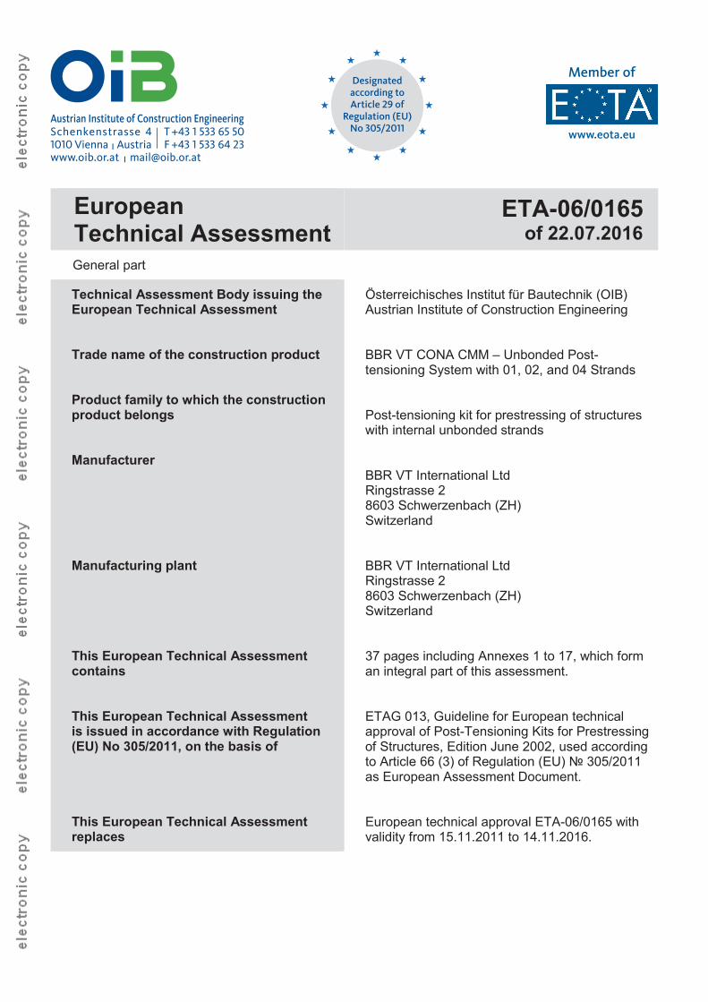
EuropeanTechnical Assessment
ETA-06/0165of 22.07.2016
General part
Technical Assessment Body issuing theEuropean Technical Assessment
Trade name of the construction product
Product family to which the construction product belongs
Manufacturer
Manufacturing plant
This European Technical Assessment contains
This European Technical Assessmentis issued in accordance with Regulation (EU) No 305/2011, on the basis of
This European Technical Assessment replaces
Österreichisches Institut für Bautechnik (OIB)Austrian Institute of Construction Engineering
BBR VT CONA CMM – Unbonded Post-tensioning System with 01, 02, and 04 Strands
Post-tensioning kit for prestressing of structures with internal unbonded strands
BBR VT International LtdRingstrasse 28603 Schwerzenbach (ZH)Switzerland
BBR VT International LtdRingstrasse 28603 Schwerzenbach (ZH)Switzerland
37 pages including Annexes 1 to 17, which form an integral part of this assessment.
ETAG 013, Guideline for European technical approval of Post-Tensioning Kits for Prestressing of Structures, Edition June 2002, used according to Article 66 (3) of Regulation (EU) № 305/2011 as European Assessment Document.
European technical approval ETA-06/0165 with validity from 15.11.2011 to 14.11.2016.
Page 2 of European Technical Assessment ETA-06/0165 of 22.07.2016,replaces European technical approval ETA-06/0165 with validity from 15.11.2011 to 14.11.2016
OIB-205-024/16-010
Table of contents
EUROPEAN TECHNICAL ASSESSMENT ETA-06/0165 OF 22.07.2016 .........................................................1
GENERAL PART ......................................................................................................................................... 1 TABLE OF CONTENTS.................................................................................................................................. 2 REMARKS .................................................................................................................................................. 5
SPECIFIC PARTS......................................................................................................................................... 5 1 TECHNICAL DESCRIPTION OF THE PRODUCT ........................................................................................5 1.1 General ...........................................................................................................................................5 PT SYSTEM................................................................................................................................................ 6 1.2 Designation and range of anchorages and couplers........................................................................6
1.2.1 Designation ............................................................................................................................6 1.2.2 Anchorage..............................................................................................................................6 1.2.3 Fixed and stressing coupler....................................................................................................6 1.2.4 Layout of the anchorage recesses..........................................................................................6
1.3 Designation and range of the tendons .............................................................................................7 1.3.1 Designation ............................................................................................................................7 1.3.2 Range ....................................................................................................................................7 1.3.2.1 General ..................................................................................................................................7 1.3.2.2 CONA CMM n06 – 140 ..........................................................................................................7 1.3.2.3 CONA CMM n06 – 150 ..........................................................................................................7 1.3.2.4 CONA CMM n06C – 165........................................................................................................7
1.4 Friction losses .................................................................................................................................8 1.5 Support of tendons..........................................................................................................................8 1.6 Slip at anchorages...........................................................................................................................8 1.7 Centre spacing and edge distances for anchorages ........................................................................9 1.8 Minimum radii of curvature of internal tendons ................................................................................9 1.9 Concrete strength at time of stressing ...........................................................................................10 COMPONENTS..........................................................................................................................................10 1.10 Strands..........................................................................................................................................10 1.11 Anchorages and couplers..............................................................................................................11
1.11.1 General ................................................................................................................................11 1.11.2 Anchor heads.......................................................................................................................11 1.11.3 Couplers...............................................................................................................................11 1.11.4 Ring wedges ........................................................................................................................11 1.11.5 Helix and additional reinforcement .......................................................................................11 1.11.6 Protection caps ....................................................................................................................12 1.11.7 Pocket former set .................................................................................................................12 1.11.8 Material specifications ..........................................................................................................12
1.12 Permanent corrosion protection.....................................................................................................12
Page 3 of European Technical Assessment ETA-06/0165 of 22.07.2016,replaces European technical approval ETA-06/0165 with validity from 15.11.2011 to 14.11.2016
OIB-205-024/16-010
1.12.1 General ................................................................................................................................12 1.12.2 Corrosion protection of the strand ........................................................................................12 1.12.3 Corrosion protection in anchorage and coupler zones..........................................................12
2 SPECIFICATION OF THE INTENDED USES IN ACCORDANCE WITH THE APPLICABLE EUROPEANASSESSMENT DOCUMENT (HEREINAFTER EAD) ................................................................................12
2.1 Intended uses................................................................................................................................12 2.2 Assumptions..................................................................................................................................13
2.2.1 General ................................................................................................................................13 2.2.2 Packaging, transport, and storage........................................................................................13 2.2.3 Design..................................................................................................................................13 2.2.3.1 General ................................................................................................................................13 2.2.3.2 Anchorage Recess...............................................................................................................13 2.2.3.3 Maximum prestressing forces...............................................................................................13 2.2.3.4 Reinforcement in the anchorage zone..................................................................................13 2.2.4 Installation............................................................................................................................14 2.2.4.1 General ................................................................................................................................14 2.2.4.2 Stressing operation ..............................................................................................................14 2.2.4.3 Restressing ..........................................................................................................................15 2.2.4.4 Welding ................................................................................................................................15
2.3 Assumed working life ....................................................................................................................15 3 PERFORMANCES OF THE PRODUCT AND REFERENCES TO THE METHODS USED FOR ITS
ASSESSMENT ..................................................................................................................................15 3.1 Essential characteristics ................................................................................................................15
3.1.1 Mechanical resistance and stability ......................................................................................17 3.1.1.1 Resistance to static load ......................................................................................................17 3.1.1.2 Resistance to fatigue............................................................................................................17 3.1.1.3 Load transfer to the structure ...............................................................................................17 3.1.1.4 Friction coefficient ................................................................................................................17 3.1.1.5 Deviation, defection (limits) ..................................................................................................17 3.1.1.6 Practicability, reliability of the installation..............................................................................17 3.1.2 Hygiene, health, and the environment ..................................................................................17 3.1.3 Related aspects of serviceability ..........................................................................................17 3.1.4 Mechanical resistance and stability ......................................................................................17 3.1.4.1 Tendons in masonry structures – Load transfer to the structure ...........................................17
3.2 Assessment methods ....................................................................................................................17 3.3 Identification ..................................................................................................................................18 4 ASSESSMENT AND VERIFICATION OF CONSTANCY OF PERFORMANCE (HEREINAFTER AVCP)
SYSTEM APPLIED, WITH REFERENCE TO ITS LEGAL BASE.....................................................................18 4.1 System of assessment and verification of constancy of performance ............................................18 4.2 AVCP for construction products for which a European Technical Assessment has been
issued............................................................................................................................................18 5 TECHNICAL DETAILS NECESSARY FOR THE IMPLEMENTATION OF THE AVCP SYSTEM, AS PROVIDED
FOR IN THE APPLICABLE EAD...........................................................................................................19 5.1 Tasks for the manufacturer............................................................................................................19
5.1.1 Factory production control ....................................................................................................19 5.1.2 Declaration of performance ..................................................................................................19
Page 4 of European Technical Assessment ETA-06/0165 of 22.07.2016,replaces European technical approval ETA-06/0165 with validity from 15.11.2011 to 14.11.2016
OIB-205-024/16-010
5.2 Tasks for the notified product certification body.............................................................................19 5.2.1 Initial inspection of the manufacturing plant and of factory production control.......................19 5.2.2 Continuing surveillance, assessment, and evaluation of factory production control ..............19 5.2.3 Audit-testing of samples taken by the notified product certification body at the
manufacturing plant or at the manufacturer's storage facilities .............................................20
ANNEXES ................................................................................................................................................21 ANNEX 1 OVERVIEW ON ANCHORAGES AND FIXED COUPLERS .................................................................21 ANNEX 2 COMPONENTS – ANCHORAGES AND FIXED COUPLERS ..............................................................22 ANNEX 3 COMPONENTS – ACCESSORY .................................................................................................23 ANNEX 4 MATERIAL SPECIFICATIONS.....................................................................................................24 ANNEX 5 STRAND SPECIFICATIONS........................................................................................................25 ANNEX 6 TENDON RANGES ...................................................................................................................26 ANNEX 7 MAXIMUM PRESTRESSING AND OVERSTRESSING FORCES .........................................................27 ANNEX 8 DIMENSIONS OF ANCHORAGES, HELIX, AND ADDITIONAL REINFORCEMENT, CENTRES
SPACING AND EDGE DISTANCE ................................................................................................28 ANNEX 9 ANCHORAGE ZONE – DIMENSIONS – MODIFICATION OF CENTRE SPACING AND EDGE
DISTANCE ..............................................................................................................................29 ANNEX 10 DIMENSIONS OF ANCHORAGE RECESSES .................................................................................30 ANNEX 11 FREE TENDON LAYOUT – TRANSITION REGIONS........................................................................31 ANNEX 12 DESCRIPTION OF WORKSTEPS – ANCHORAGE – FIXED COUPLER CONSTRUCTION STAGES 1
AND 2....................................................................................................................................32 ANNEX 13 CONSTRUCTION STAGES – ANCHORAGES AND FIXED COUPLERS ...............................................33 ANNEX 14 CONTENTS OF THE PRESCRIBED TEST PLAN.............................................................................34 ANNEX 15 AUDIT TESTING ......................................................................................................................35 ANNEX 16 ESSENTIAL CHARACTERISTICS FOR THE INTENDED USES...........................................................36 ANNEX 17 REFERENCE DOCUMENTS .......................................................................................................37
Page 5 of European Technical Assessment ETA-06/0165 of 22.07.2016,replaces European technical approval ETA-06/0165 with validity from 15.11.2011 to 14.11.2016
OIB-205-024/16-010
Remarks Translations of the European Technical Assessment in other languages shall fully correspond to the original issued document and should be identified as such. Communication of the European Technical Assessment, including transmission by electronic means, shall be in full. However, partial reproduction may be made with the written consent of Österreichisches Institut für Bautechnik. Any partial reproduction has to be identified as such.
Specific parts
1 Technical description of the product
1.1 General The European Technical Assessment1 – ETA – applies to a kit, the PT system
BBR VT CONA CMM Unbonded Post-tensioning System with 01, 02, and 04 Strands,
comprising the following components, see Annex 1 and Annex 2. Tendon
Unbonded tendons with 01, 02, or 04 tensile elements Tensile element
7-wire prestressing steel strands with nominal diameters and maximum characteristic tensile strengths as given in Table 1, factory-provided with a corrosion protection system consisting of a corrosion-protective filling material and a HDPE-sheathing.
Table 1: Tensile elements
Nominal diameter Nominal cross-sectional area
Maximum characteristic tensile strength
mm mm2 MPa
15.3 1401 860
15.7 150
15.2 1) 165 1 8201) Compacted strandNOTE 1 MPa = 1 N/mm2
Anchorage and coupler Anchorage of the strands with ring wedges End anchorage
Fixed (passive) anchor or stressing (active) anchor as end anchorage for 01, 02, and04 strands
Fixed or stressing coupler Sleeve coupler for 01 and 04 strands
Helix and additional reinforcement in the region of the anchorage 1 ETA-06/0165 was firstly issued in 2006 as European technical approval with validity from 15.11.2006, extended in 2011 with
validity from 15.11.2011 and converted in 2016 to European Technical Assessment ETA-06/0165 of 22.07.2016.
Page 6 of European Technical Assessment ETA-06/0165 of 22.07.2016,replaces European technical approval ETA-06/0165 with validity from 15.11.2011 to 14.11.2016
OIB-205-024/16-010
Corrosion protection for tensile elements, couplers, and anchorages
PT system 1.2 Designation and range of anchorages and couplers 1.2.1 Designation
Anchorage e.g. (S) A CONA CMM 0106 (single) – 140
Fixed (F) or stressing (S) Anchor head Designation of the tendon
Fixed coupler e.g. H CONA CMM 0106 (single) – 140 – 1.BA
Coupler anchor head Designation of the tendon Construction stage 1 (1.BA) or 2 (2.BA)
1.2.2 Anchorage The anchor heads of the fixed and stressing anchorages are identical, see Annex 1. A differentiation is needed for the construction works. The principal dimensions of the anchorages are given in Annex 2 and Annex 3. Fixed anchorages that are accessible may be prelocked. Fixed anchorages that are not accessible are prelocked with a prelocking force as specified in Table 2. The ring wedges are secured with rings between ring wedges and protection caps.
1.2.3 Fixed and stressing coupler Couplers are intended as fixed couplers only. The principal dimensions of the couplers are given in Annex 2 and Annex 3. Fixed couplers are for tendons with 01 or 04 prestressing strands, see Annex 1. The prestressing force at the second construction stage may not be greater than that at the first construction stage, neither during construction, nor in the final state, nor due to any load combination. The tendon of construction stage 2 is coupled by screwing the coupler sleeve entirely on the threaded part of the coupler anchor head 1.BA (construction stage 1). The coupler anchor head 2.BA (construction stage 2) is prelocked with a prelocking force as specified in Table 2. At coupler anchor head H CONA CMM (single) – 2.BA (construction stage 2), the ring wedges are secured with wedge holding rings and at coupler anchor head H CONA CMM (four) – 2.BA (construction stage 2), the ring wedges are secured with a wedge holding plate.
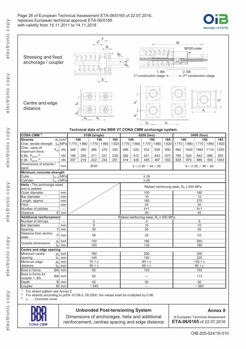
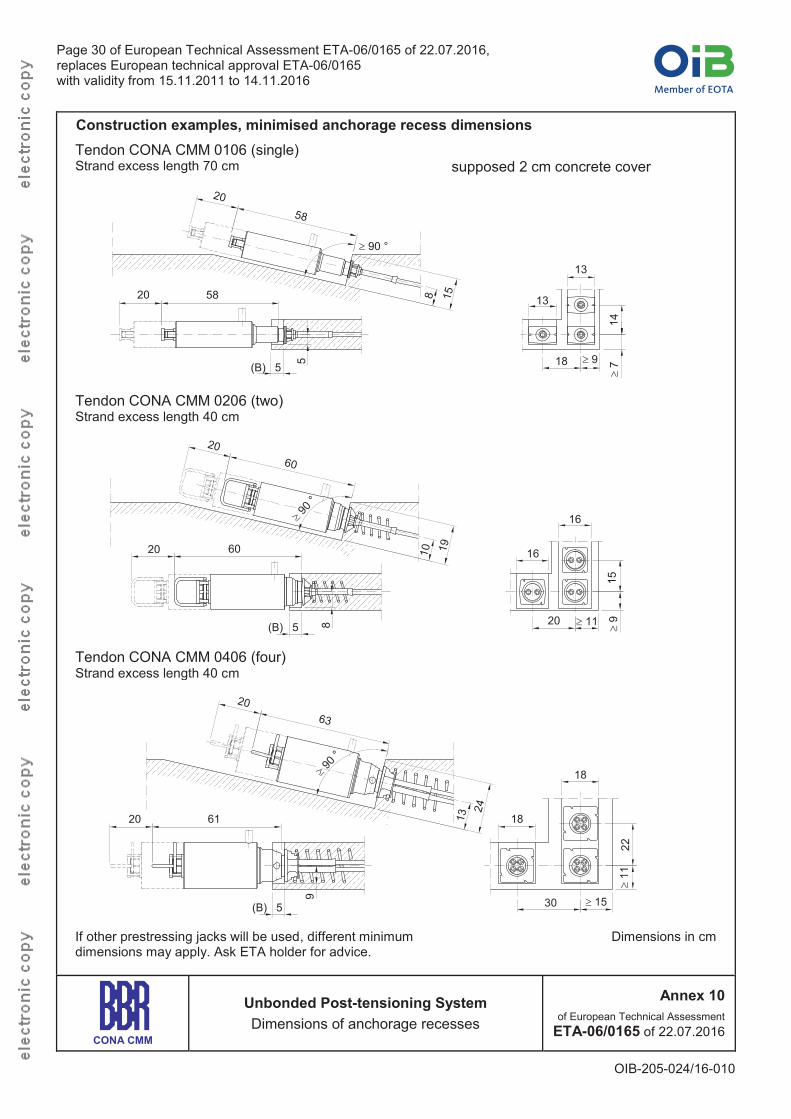
1.2.4 Layout of the anchorage recesses All anchor heads are placed perpendicular to the axis of the tendon, see Annex 8. In Annex 8 and Annex 10 the minimum dimensions of the anchorage recesses are given. The dimensions of the anchorage recesses are adapted to the prestressing jacks used. The ETA holder saves for reference information on the minimum dimensions of the anchorage recesses. The formwork for the anchorage recesses should be slightly conical for ease of removal. The anchorage recesses are designed in such a way as to permit a reinforced concrete cover with the required dimensions, and in any case with a thickness of at least 20 mm.
Page 7 of European Technical Assessment ETA-06/0165 of 22.07.2016,replaces European technical approval ETA-06/0165 with validity from 15.11.2011 to 14.11.2016
OIB-205-024/16-010
1.3 Designation and range of the tendons 1.3.1 Designation
Tendon e.g. CONA CMM 0106 (single) – 140
Unbonded PTNumber of strands 0106 (single), 0206 (two), or 0406 (four) Cross-sectional area of strands (140, 150, or 165 mm2) The characteristic tensile strength of the strands (1 770, 1 820, or 1 860 MPa) may be indicated optionally.
1.3.2 Range 1.3.2.1 General
Prestressing and overstressing forces are given in the corresponding standards and regulations in force at the place of use. The maximum prestressing and overstressing forces are listed in Annex 7. The tendons consist of 01, 02, or 04 seven-wire prestressing steel strands, factory-provided with a corrosion protection system consisting of corrosion-protective filling material and an HDPE-sheathing.
1.3.2.2 CONA CMM n06 – 1407-wire prestressing steel strand
Nominal diameter ....................................................... 15.3 mmNominal cross-sectional area ...................................... 140 mm2 Maximum characteristic tensile strength ...... 1 770 or 1 860 MPa
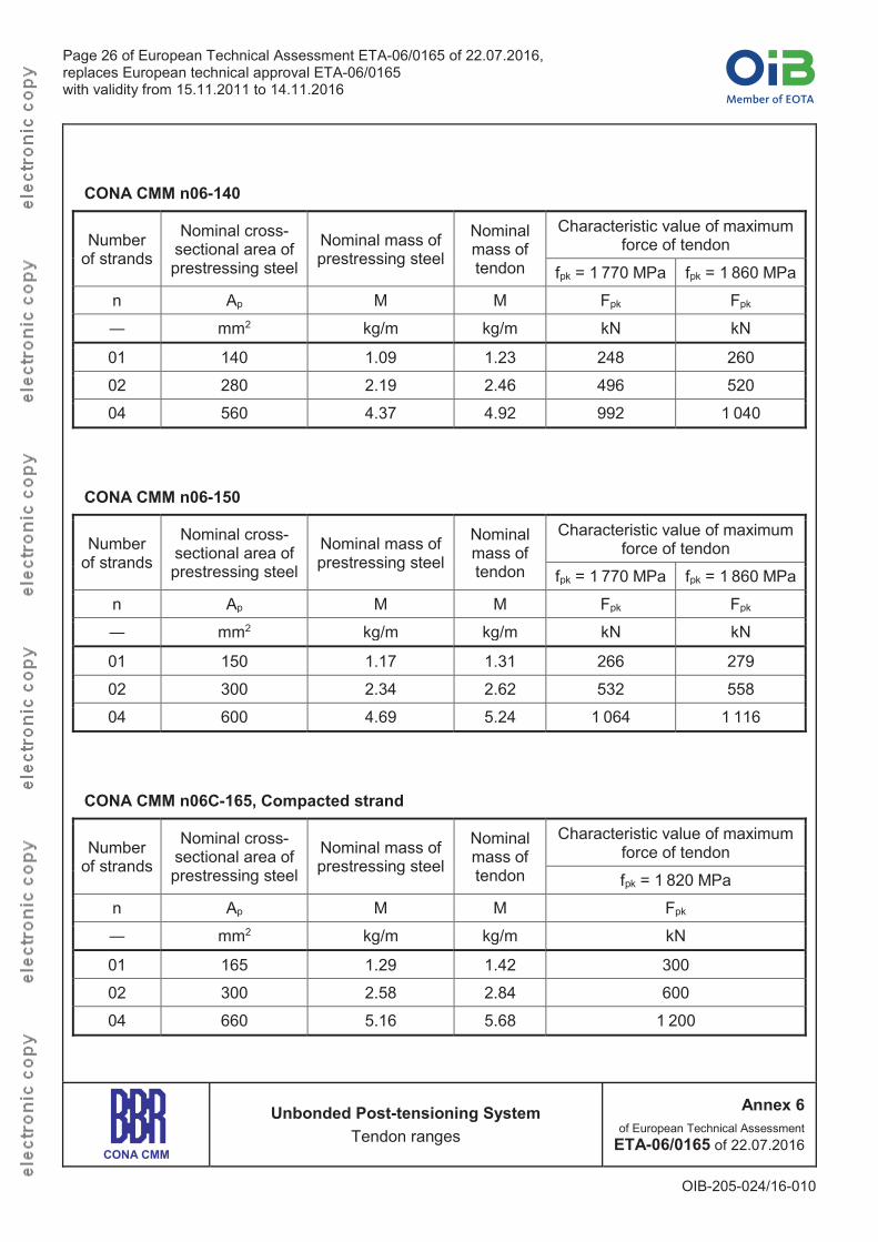
Annex 6 lists the available tendon range for CONA CMM n06 – 140.1.3.2.3 CONA CMM n06 – 150
7-wire prestressing steel strand Nominal diameter ....................................................... 15.7 mmNominal cross-sectional area ...................................... 150 mm2 Maximum characteristic tensile strength ...... 1 770 or 1 860 MPa
Annex 6 lists the available tendon range for CONA CMM n06 – 150.1.3.2.4 CONA CMM n06C – 165
Compacted 7-wire prestressing steel strand Nominal diameter ....................................................... 15.2 mmNominal cross-sectional area ...................................... 165 mm2 Maximum characteristic tensile strength .................... 1 820 MPa
Annex 6 lists the available tendon range for CONA CMM n06C – 165.
Page 8 of European Technical Assessment ETA-06/0165 of 22.07.2016,replaces European technical approval ETA-06/0165 with validity from 15.11.2011 to 14.11.2016
OIB-205-024/16-010
1.4 Friction losses For calculation of loss of prestressing force due to friction Coulomb's law applies. Due to the filling of the HDPE-sheathing of the individual monostrands or VT CMM Bands with corrosion protective material, the friction coefficient μ is very low. The calculation of the friction losses is carried out using the equation
Fx = F0 · e - · ( + k · x)
Where Fx ..........kN ............. Prestressing force at a distance x along the tendon F0..........kN ............. Prestressing force at x = 0 m
......... rad-1............ Friction coefficient; = 0.06 rad-1 (CONA CMM n06 – 140/150) or 0.05 rad-1 (CONA CMM n06C – 165)
.......... rad ............. Sum of angular displacements over distance x, irrespective of direction or sign
k ........ rad/m ........... Wobble coefficient; k = 8.73 · 10-3 rad/m (= 0.5 °/m) x ........... m .............. Distance along the tendon from the point where the prestressing force is
equal to F0 NOTE 1 rad = 1 m/m = 1
If band-shaped tendons CONA CMM 150/165 with two or four strands are installed upright with flat-wise curvature and connected at support distances of 1.15 to 1.30 m, the wobble coefficient is k = 4.37 · 10-3 rad/m (= 0.25 °/m). Friction losses in anchorages are low and do not have to be taken into consideration in design and execution.
1.5 Support of tendons The individual monostrands or VT CMM Bands are fixed in their position. Spacing of supports is: 1 Normally
Individual monostrands (01 strand) and VT CMM Bands with 02 and 04 strands ........................................................... 1.00 to 1.30 m
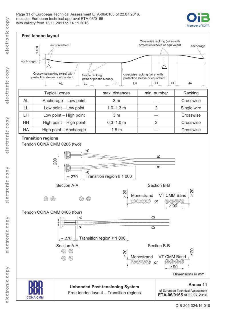
2 Free tendon layout in 45 cm thick slabs In the transition region between a) high tendon position and anchorage (e.g. cantilever) ........................................... 1.50 m b) low and high tendon position or low tendon position and anchorage .................... 3.00 m
In regions of high or low tendon position the tendons are connected in an appropriate way to the reinforcement mesh, at least at two points with a spacing of 0.3 to 1.3 m. The reinforcement mesh is fixed in its position. Special spacers for tendons are therefore not required. For details see Annex 11.
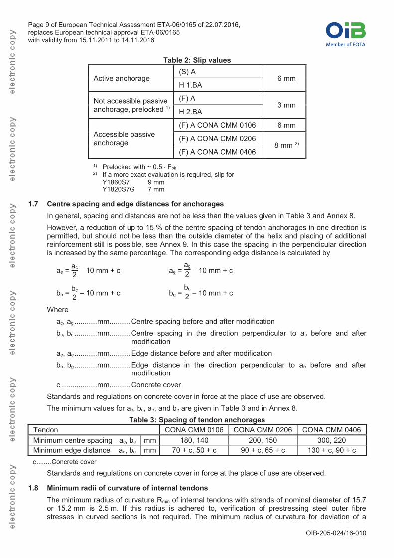
1.6 Slip at anchorages Table 2 specifies the slip at anchorages that is taken into consideration in calculations of tendon elongations and tendon forces.
Page 9 of European Technical Assessment ETA-06/0165 of 22.07.2016,replaces European technical approval ETA-06/0165 with validity from 15.11.2011 to 14.11.2016
OIB-205-024/16-010
Table 2: Slip values
Active anchorage(S) A
6 mmH 1.BA
Not accessible passive anchorage, prelocked 1)
(F) A3 mm
H 2.BA
Accessible passive anchorage
(F) A CONA CMM 0106 6 mm
(F) A CONA CMM 02068 mm 2)
(F) A CONA CMM 0406
1) Prelocked with ~ 0.5 Fpk2) If a more exact evaluation is required, slip for
Y1860S7 9 mmY1820S7G 7 mm
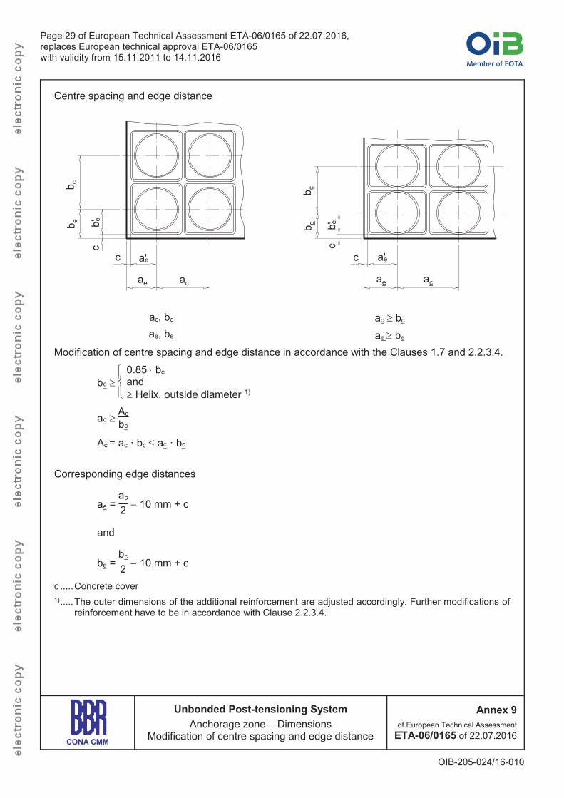
1.7 Centre spacing and edge distances for anchorages In general, spacing and distances are not be less than the values given in Table 3 and Annex 8. However, a reduction of up to 15 % of the centre spacing of tendon anchorages in one direction is permitted, but should not be less than the outside diameter of the helix and placing of additional reinforcement still is possible, see Annex 9. In this case the spacing in the perpendicular direction is increased by the same percentage. The corresponding edge distance is calculated by
ae = ac
2 – 10 mm + c ae = ac
2 10 mm + c
be = bc
2 – 10 mm + c be = bc
2 10 mm + c
Where ac, ac ...........mm.......... Centre spacing before and after modification bc, bc ...........mm.......... Centre spacing in the direction perpendicular to ac before and after
modification ae, ae...........mm.......... Edge distance before and after modification be, be...........mm.......... Edge distance in the direction perpendicular to ae before and after
modification c .................mm.......... Concrete cover
Standards and regulations on concrete cover in force at the place of use are observed. The minimum values for ac, bc, ae, and be are given in Table 3 and in Annex 8.
Table 3: Spacing of tendon anchorages Tendon CONA CMM 0106 CONA CMM 0206 CONA CMM 0406Minimum centre spacing ac, bc mm 180, 140 200, 150 300, 220Minimum edge distance ae, be mm 70 + c, 50 + c 90 + c, 65 + c 130 + c, 90 + cc........Concrete cover
Standards and regulations on concrete cover in force at the place of use are observed.
1.8 Minimum radii of curvature of internal tendons The minimum radius of curvature Rmin of internal tendons with strands of nominal diameter of 15.7 or 15.2 mm is 2.5 m. If this radius is adhered to, verification of prestressing steel outer fibre stresses in curved sections is not required. The minimum radius of curvature for deviation of a
Page 10 of European Technical Assessment ETA-06/0165 of 22.07.2016,replaces European technical approval ETA-06/0165 with validity from 15.11.2011 to 14.11.2016
OIB-205-024/16-010
tendon with multistrand anchorages in the anchorage zone outside the transition tubes up to the last reinforcement steel bar is 3.5 m.
1.9 Concrete strength at time of stressing Concrete in conformity with EN 2062 is used. At the time of stressing the mean concrete compressive strength, fcm, 0, is at least 24 MPa (cube strength, 150 mm cube) or 20 MPa (cylinder strength, 150 mm cylinder diameter). The concrete test specimen are subjected to the same curing conditions as the structure. For partial prestressing with 30 % of the full prestressing force the actual mean value of the concrete compressive strength is at least 0.5 · fcm, 0, cube or 0.5 · fcm, 0, cylinder. Intermediate values may be interpolated linearly according to Eurocode 2. Helix, additional reinforcement, centre spacing and edge distance are taken from Annex 8, see also the Clauses 1.11.5 and 2.2.3.4. Where
fcm, 0, cube 150 .............. Mean concrete compressive strength at time of stressing, determined at cubes, 150 mm
fcm, 0, cylinder 150 ......... Mean concrete compressive strength at time of stressing, determined at cylinders, diameter 150 mm
Components 1.10 Strands
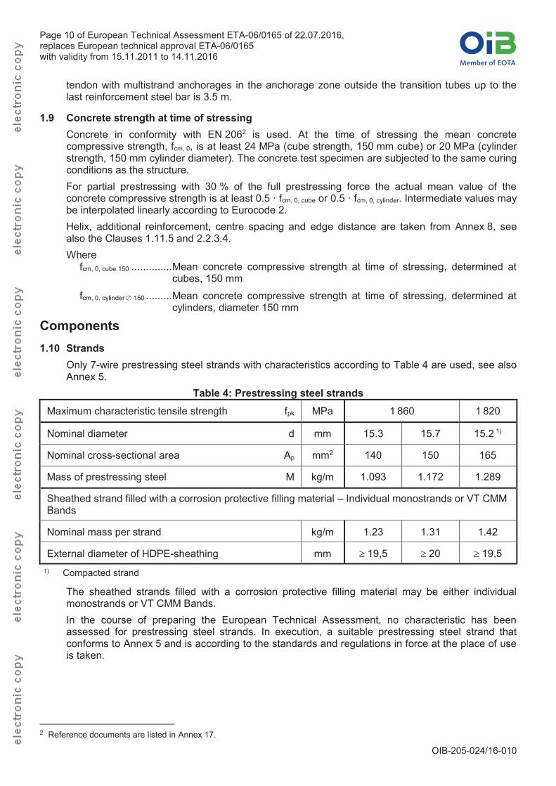
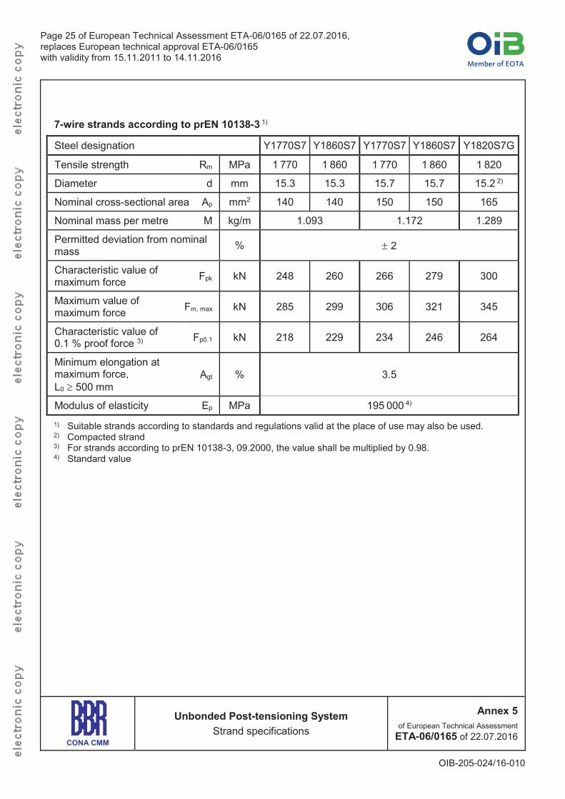
Only 7-wire prestressing steel strands with characteristics according to Table 4 are used, see also Annex 5.
Table 4: Prestressing steel strands Maximum characteristic tensile strength fpk MPa 1 860 1 820
Nominal diameter d mm 15.3 15.7 15.2 1)
Nominal cross-sectional area Ap mm2 140 150 165
Mass of prestressing steel M kg/m 1.093 1.172 1.289
Sheathed strand filled with a corrosion protective filling material – Individual monostrands or VT CMM Bands
Nominal mass per strand kg/m 1.23 1.31 1.42
External diameter of HDPE-sheathing mm 19,5 20 19,51) Compacted strand
The sheathed strands filled with a corrosion protective filling material may be either individual monostrands or VT CMM Bands. In the course of preparing the European Technical Assessment, no characteristic has been assessed for prestressing steel strands. In execution, a suitable prestressing steel strand that conforms to Annex 5 and is according to the standards and regulations in force at the place of use is taken.
2 Reference documents are listed in Annex 17.
Page 11 of European Technical Assessment ETA-06/0165 of 22.07.2016,replaces European technical approval ETA-06/0165 with validity from 15.11.2011 to 14.11.2016
OIB-205-024/16-010
1.11 Anchorages and couplers 1.11.1 General
The components of anchorages and couplers are in conformity with the specifications given in Annex 2 and Annex 3 and the technical file3. Therein the component dimensions, materials, and material identification data with tolerances are given.
1.11.2 Anchor heads The anchor heads are made of cast iron with spheroidal graphite. They provide regularly arranged conical holes to accommodate 01, 02, or 04 strands, and ring wedges. The load transfer to the concrete occurs in two planes. The anchor head has a cylindrical extension with an internal thread to screw-in a protection cap, which will be filled with corrosion protective filling material to protect the ring wedges and the strands. The outlet end of the holes is formed in such a way as to allow the transition pipes to be inserted tension-proof. The transition pipes act as the transition from the anchor head to the sheathing of the strands.
1.11.3 Couplers Fixed couplers are provided for tendons with 01 or 04 strands. They consist of a coupler anchor head 1.BA (construction stage 1) and a coupler anchor head 2. BA (construction stage 2). The coupler anchor head 1. BA (construction stage 1) is the same basic body as the anchor heads of active and passive anchorages for 01 and 04 strands, but provides a cylindrical extension with an external thread to accommodate the coupler sleeve. The connection between coupler anchor heads 1.BA (construction stage 1) and 2. BA (construction stage 2) is by means of a coupler sleeve, a steel tube featuring an internal thread, a threaded bore to accommodate the filling device and a bore for ventilation. The coupler anchor head 2. BA (construction stage 2) for 01 strand is either a cast iron head with a conical hole or a steel body with a conical bore. The coupler anchor head 2 BA (construction stage 2) for 04 strands is a steel body with conical bores. All coupler anchor heads provide a machined external thread for the coupler sleeve. The end surface of the fixed coupler H CONA CMM 0406 (four) is provided with a BDSD-plate to permit settlement of the coupler during stressing.
1.11.4 Ring wedges The ring wedges are in three pieces, which are held together by spring rings. Two ring wedges,i.e. H or F, are used. Within one anchorage or coupler only one of these ring wedges is used. Wedge holding rings serve to secure the ring wedges after prelocking. The fastening of the ring wedges of the prelocked coupler anchor head CONA CMM 0406 (four) – 140/150/165 – 2.BA (construction stage 2) is made by means of a wedge holding plate.
1.11.5 Helix and additional reinforcement The helix and the additional reinforcement are made of ribbed reinforcing steel. The end of the helix on the anchorage side is welded to the following turn. The helix is placed in the tendon axis. Dimensions of helix and additional reinforcement conforms to the values specified in Annex 8, see also Clause 2.2.3.4. If required for a specific project design, the reinforcement given in Annex 8 may be modified in accordance with the respective regulations in force at the place of use as well as with the relevant approval of the local authorities and of the ETA holder, to provided equivalent performance.
3 The technical file of the European Technical Assessment is deposited at Österreichisches Institut für Bautechnik.

Page 12 of European Technical Assessment ETA-06/0165 of 22.07.2016,replaces European technical approval ETA-06/0165 with validity from 15.11.2011 to 14.11.2016
OIB-205-024/16-010
1.11.6 Protection caps Protection caps are made of plastic. They are screwed into the anchor head and for anchorages with two or four prestressing steel strands are provided with an air vent.
1.11.7 Pocket former set The pocket former set is made of plastic, see Annex 3. It consists of one universal mandrel with nut and two pocket formers with different dimensions. The pocket formers are employed to form anchorage recesses for stressing anchorages (S) A CONA CMM 0106.
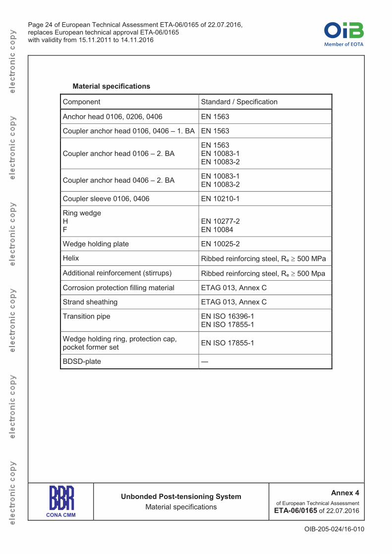
1.11.8 Material specifications Annex 4 lists the material standards or specifications of the components.
1.12 Permanent corrosion protection 1.12.1 General
In the course of preparing the European Technical Assessment no characteristic has been assessed for components and materials of the corrosion protection system referred to in the Clauses 1.12.2 and 1.12.3. In execution, all components or materials have to be selected according to the standards and regulations in force at the place of use. Where no such standards or regulations are present, components and materials in accordance with ETAG 013, Annex C.1, should be deemed to be acceptable.
1.12.2 Corrosion protection of the strand The strands are sheathed in the factory with an extruded HDPE-sheathing with a thickness of at least 1.0 mm. The actual thickness of the sheathing is in accordance with the standards and regulations in force at the place of use.
1.12.3 Corrosion protection in anchorage and coupler zones The voids inside the HDPE-sheathing are filled with corrosion protection filling material. When mounting the anchorage, the sheathing is removed along the required length. During construction the strand excess lengths protruding from the anchorage are temporarily protected with cut-off HDPE-sheaths. All voids of the anchorages and couplers are filled with corrosion protection filling material according to the installation instructions in Annex 12. Anchorages that are prelocked receive their corrosion protection immediately after the prelocking operation by filling with corrosion protection filling material and screwing-on of the protection cap.
2 Specification of the intended uses in accordance with the applicable European Assessment Document (hereinafter EAD)
2.1 Intended uses The PT system is intended to be used for the prestressing of structures. The specific intended uses are listed in Table 5.
Table 5: Intended uses Line № Use category
Use categories according to tendon configuration and material of structure
1 Internal unbonded tendon for concrete and composite structures
2 For special structures according to Eurocode 2 and Eurocode 4
Optional use category
3 Tendon for use in structural masonry construction as internal tendon
Page 13 of European Technical Assessment ETA-06/0165 of 22.07.2016,replaces European technical approval ETA-06/0165 with validity from 15.11.2011 to 14.11.2016
OIB-205-024/16-010
2.2 Assumptions 2.2.1 General
The manufacturer undertakes the appropriate measures and prepares advice on product packaging, transport, and storage. It is the responsibility of the manufacturer of the product to ensure that this information is given to those who are concerned.
2.2.2 Packaging, transport, and storage Advice on packaging, transport, and storage includes. During transport of prefabricated tendons a minimum diameter of curvature of 1.45 to 1.75 m
or as specified by the manufacturer of the strand is observed. Temporary protection of prestressing steel and components in order to prevent corrosion
during transport from production site to job site Transportation, storage, and handling of the prestressing steel and other components in a
manner as to avoid damage by mechanical or chemical impact Protection of prestressing steel and other components from moisture Keeping tensile elements separate from areas where welding operations are performed
2.2.3 Design 2.2.3.1 General
It is the responsibility of the ETA holder to ensure that all necessary information on design and installation is submitted to those responsible for design and execution of the structures executed with "BBR VT CONA CMM – Unbonded Post-tensioning System with 01, 02, and 04 Strands". Design of the structure permits correct installation and stressing of the tendons. The reinforcement in the anchorage zone permits correct placing and compacting of concrete.
2.2.3.2 Anchorage Recess The anchorage recess is designed so as to ensure a concrete cover of at least 20 mm at the protection caps in the final state. Clearance is required for the handling of prestressing jacks. In order to allow for imperfections and to ease the cutting of the strand excess lengths it is recommended to increase the dimensions of the recesses. The forms for the recesses should be slightly conical for easy removal. If other prestressing jacks than those shown in Annex 10 are used, the ETA holder keeps information on prestressing jacks and minimum dimensions of anchorage recesses. In case of failure the bursting out of prestressing steels is prevented. Sufficient protection is provided by e.g. a cover of reinforced concrete.
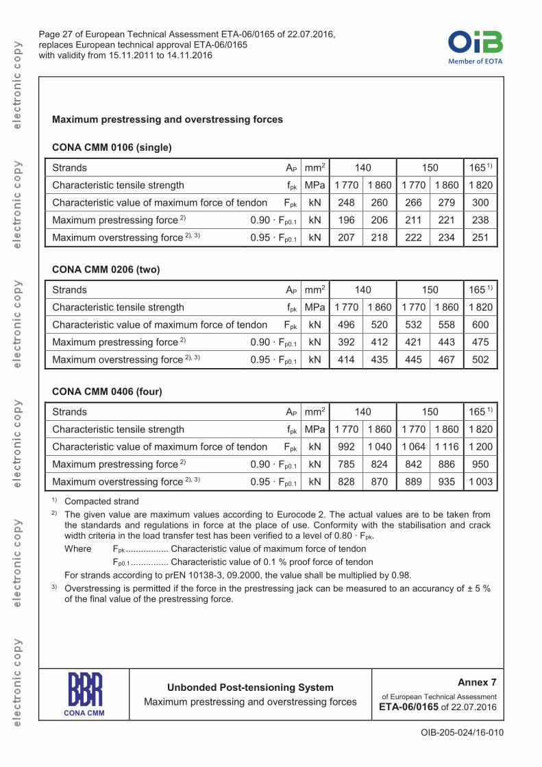
2.2.3.3 Maximum prestressing forces The prestressing and overstressing forces are specified in the respective standards and regulations in force at place of use. Annex 7 lists the maximum possible prestressing and overstressing forces.
2.2.3.4 Reinforcement in the anchorage zone Verification of transfer of prestressing forces to structural concrete is not required if centre spacing and edge distance of anchorages and couplers as well as grade and dimensions of additional reinforcement, see Annex 8, are conformed to. In the case of grouped anchorages the additional reinforcement of the individual anchorages can be combined, provided appropriate anchorage is ensured. However, number, cross-sectional area, and position with respect to the anchor heads remain unchanged.
Page 14 of European Technical Assessment ETA-06/0165 of 22.07.2016,replaces European technical approval ETA-06/0165 with validity from 15.11.2011 to 14.11.2016
OIB-205-024/16-010
The reinforcement of the structure is not employed as additional reinforcement. Reinforcement exceeding the required reinforcement of the structure may be used as additional reinforcement, provided appropriate placing is possible. The forces outside the area of the additional reinforcement are verified and, if necessary, dealt with by appropriate reinforcement. If required for a specific project design, the reinforcement given in Annex 8 may be modified in accordance with the respective regulations in force at the place of use as well as with the relevant approval of the local authority and of the ETA holder to provide equivalent performance.
2.2.4 Installation 2.2.4.1 General
Assembly and installation of tendons is only carried out by qualified PT specialist companies with the required resources and experience in the use of multi strand unbonded post-tensioning systems, see ETAG 013, Annex D.1 and CWA 14646. The respective standards and regulations in force at the place of use are considered. The company's PT site manager has a certificate, stating that she or he has been trained by the ETA holder and that she or he possesses the necessary qualifications and experience with the “BBR VT CONA CMM –Unbonded Post-tensioning System with 01, 02, and 04 Strands”. Couplers are situated in a straight tendon section. The tendons are carefully handled during production, transport, storage, and installation. The corrosion protected HDPE sheathed prestressing strands are usually delivered to site in coils with an internal diameter of 1.45 to 1.75 m.In the anchorage zone, the webs of the VT CMM Bands are longitudinally cut over a length of 1.3 m from the end. The layout of the transition zone is shown in Annex 11. The sequence of work steps for installation of anchorage and fixed coupler is described in Annex 12 and in Annex 13 representations of construction stages are shown. Before placing the concrete a final check of the installed tendons is carried out. At that time, the passive anchorages mounted at the PT works are randomly checked for proper seating of the ring wedges and complete filling of the protection caps with corrosion protective filling material.In the case of minor damage of the sheathing, the damaged area is cleaned and sealed with an adhesive tape.
2.2.4.2 Stressing operation With a mean concrete compressive strength in the anchorage zone according to the values laid down in Annex 8 full prestressing may be applied. Stressing and, if applicable, wedging is carried out using a suitable prestressing jack. The wedging force corresponds to approximately 25 kN per wedge. Elongations and prestressing forces are checked continuously during the stressing operation. The results of the stressing operation are recorded and the measured elongations compared with the prior calculated values. After releasing the prestressing force from the prestressing jack, the tendon is pulled in and reduces the elongation by the amount of slip at the anchor head. Information on the prestressing equipment has been submitted to Österreichisches Institut für Bautechnik. The ETA holder keeps available information on prestressing jacks and appropriate clearance behind the anchorage. The safety-at-work and health protection regulations shall be complied with.
Page 15 of European Technical Assessment ETA-06/0165 of 22.07.2016,replaces European technical approval ETA-06/0165 with validity from 15.11.2011 to 14.11.2016
OIB-205-024/16-010
2.2.4.3 Restressing Restressing of tendons in combination with release and reuse of wedges is permitted, whereas the wedges bite into a least 15 mm of virgin strand surface and no wedge bite remains inside the final length of the tendon between anchorages.
2.2.4.4 Welding Welding is not intended and it is not permitted to weld on built-in components of post-tensioning systems. In case of welding operations near tendons precautionary measures are required to avoid damage to the corrosion protection system.
2.3 Assumed working life The European Technical Assessment is based on an assumed working life of the PT system of 100 years, provided that the PT system is subject to appropriate installation, use, and maintenance, see Clause 2.2. The indications given as to the working life of the PT system cannot be interpreted as a guarantee neither given by the product manufacturer or his representative nor by the Technical Assessment Body, but are regarded only as a means for selecting the appropriate products in relation to the expected economically reasonable working life of the works4.
3 Performances of the product and references to the methods used for its assessment
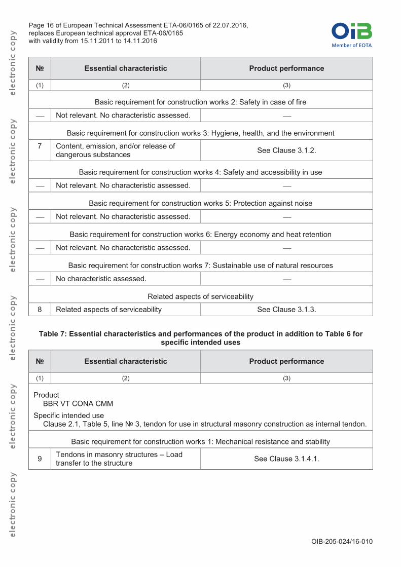
3.1 Essential characteristics The performances of the PT system for the essential characteristics are given in Table 6 andTable 7. In Annex 16 the combinations of essential characteristics and corresponding intended uses are listed.
Table 6: Essential characteristics and performances of the product
№ Essential characteristic Product performance
(1) (2) (3)
ProductBBR VT CONA CMM
Intended useThe PT system is intended to be used for the prestressing of structures, Clause 2.1, Table 5, lines № 1 and 2.
Basic requirement for construction works 1: Mechanical resistance and stability
1 Resistance to static load See Clause 3.1.1.1.
2 Resistance to fatigue See Clause 3.1.1.2.
3 Load transfer to the structure See Clause 3.1.1.3.
4 Friction coefficient See Clause 3.1.1.4.
5 Deviation, deflection (limits) See Clause 3.1.1.5.
6 Practicability, reliability of installation See Clause 3.1.1.6.
4 The real working life of a product incorporated in a specific works depends on the environmental conditions to which that
works are subject, as well as on the particular conditions of design, execution, use and maintenance of that works. Therefore, it cannot be excluded that in certain cases the real working life of the product may also be shorter than the assumed working life.
Page 16 of European Technical Assessment ETA-06/0165 of 22.07.2016,replaces European technical approval ETA-06/0165 with validity from 15.11.2011 to 14.11.2016
OIB-205-024/16-010
№ Essential characteristic Product performance
(1) (2) (3)
Basic requirement for construction works 2: Safety in case of fire
Not relevant. No characteristic assessed.
Basic requirement for construction works 3: Hygiene, health, and the environment
7 Content, emission, and/or release of dangerous substances See Clause 3.1.2.
Basic requirement for construction works 4: Safety and accessibility in use
Not relevant. No characteristic assessed.
Basic requirement for construction works 5: Protection against noise
Not relevant. No characteristic assessed.
Basic requirement for construction works 6: Energy economy and heat retention
Not relevant. No characteristic assessed.
Basic requirement for construction works 7: Sustainable use of natural resources
No characteristic assessed.
Related aspects of serviceability
8 Related aspects of serviceability See Clause 3.1.3.
Table 7: Essential characteristics and performances of the product in addition to Table 6 for specific intended uses
№ Essential characteristic Product performance
(1) (2) (3)
ProductBBR VT CONA CMM
Specific intended useClause 2.1, Table 5, line № 3, tendon for use in structural masonry construction as internal tendon.
Basic requirement for construction works 1: Mechanical resistance and stability
9 Tendons in masonry structures – Load transfer to the structure See Clause 3.1.4.1.
Page 17 of European Technical Assessment ETA-06/0165 of 22.07.2016,replaces European technical approval ETA-06/0165 with validity from 15.11.2011 to 14.11.2016
OIB-205-024/16-010
3.1.1 Mechanical resistance and stability 3.1.1.1 Resistance to static load
The PT system as described in the ETA meets the acceptance criteria of ETAG 013, Clause 6.1.1-I. The characteristic values of maximum force, Fpk, of the tendon for prestressing steel strands according to Annex 5 are listed in Annex 6.
3.1.1.2 Resistance to fatigue The PT system as described in the ETA meets the acceptance criteria of ETAG 013, Clause 6.1.2-I. The characteristic values of maximum force, Fpk, of the tendon for prestressing steel strands according to Annex 5 are listed in Annex 6.
3.1.1.3 Load transfer to the structure The PT system as described in the ETA meets the acceptance criteria of ETAG 013, Clause 6.1.3-I. The characteristic values of maximum force, Fpk, of the tendon for prestressing steel strands according to Annex 5 are listed in Annex 6.
3.1.1.4 Friction coefficient The PT system as described in the ETA meets the acceptance criteria of ETAG 013, Clause 6.1.4-I. For friction losses including friction coefficient see Clause 1.4.
3.1.1.5 Deviation, defection (limits) The PT system as described in the ETA meets the acceptance criteria of ETAG 013,Clause 6.1.5-I. For minimum radii of curvature see Clause 1.8.
3.1.1.6 Practicability, reliability of the installation The PT system as described in the ETA meets the acceptance criteria of ETAG 013,Clause 6.1.6-I.
3.1.2 Hygiene, health, and the environment Content, emission, and/or release of dangerous substances is determined according to ETAG 013, Clause 5.3.1. No dangerous substances is the performance of the PT system in this respect. A manufacturer’s declaration to this effect has been submitted.
NOTE In addition to specific clauses relating to dangerous substances in the European Technical Assessment, there may be other requirements applicable to the product falling within their scope, e.g. transposed European legislation and national laws, regulations, and administrative provisions. These requirements also need to be complied with, when and where they apply.
3.1.3 Related aspects of serviceability The PT system as described in the ETA meets the acceptance criteria of ETAG 013, Clause 6.7.
3.1.4 Mechanical resistance and stability 3.1.4.1 Tendons in masonry structures – Load transfer to the structure
Load transfer of prestressing force to masonry structures is via concrete or steel members designed according to the European Technical Assessment, especially according to the Clauses 1.7, 1.9, 1.11.5, and 2.2.3.4 or to Eurocode 3 respectively. The concrete or steel members have such dimensions as to permit a force of 1.1 · Fpk being transferred into the masonry. The verification is performed according to Eurocode 6 as well as to the respective standards and regulations in force at the place of use. The characteristic values of maximum force, Fpk, of the tendon for prestressing steel strands according to Annex 5are listed in Annex 6.
3.2 Assessment methods The assessment of the essential characteristics in Clause 3.1 of the PT system for the intended uses and in relation to the requirements for mechanical resistance and stability, and for hygiene, health, and the environment in the sense of the basic requirements for construction works № 1 and
Page 18 of European Technical Assessment ETA-06/0165 of 22.07.2016,replaces European technical approval ETA-06/0165 with validity from 15.11.2011 to 14.11.2016
OIB-205-024/16-010
3 of Regulation (EU) № 305/2011 has been made in accordance with the Guideline for European technical approvals of “Post-Tensioning Kits for Prestressing of Structures”, ETAG 013, Edition June 2002, used according to Article 66 3. of Regulation (EU) № 305/2011 as European Assessment Document, based on the assessment for internal unbonded PT systems.
3.3 Identification The European Technical Assessment for the PT system is issued on the basis of agreed data5 that identify the assessed product. Changes to materials, to composition, or to characteristics of the product, or to the production process could result in these deposited data being incorrect. Österreichisches Institut für Bautechnik should be notified before the changes are introduced, as an amendment of the European Technical Assessment is possibly necessary.
4 Assessment and verification of constancy of performance (hereinafter AVCP) system applied, with reference to its legal base
4.1 System of assessment and verification of constancy of performance According to the Commission Decision 98/456/EC the system of assessment and verification of constancy of performance to be applied to the PT system is System 1+. System 1+ is detailed in Commission Delegated Regulation (EU) № 568/2014 of 18 February 2014, Annex, 1.1., and provides for the following items. (a) The manufacturer shall carry out
(i) factory production control; (ii) further testing of samples taken at the manufacturing plant by the manufacturer in
accordance with the prescribed test plan6.(b) The notified product certification body shall decide on the issuing, restriction, suspension or
withdrawal of the certificate of constancy of performance of the construction product on the basis of the outcome of the following assessments and verifications carried out by that body (i) an assessment of the performance of the construction product carried out on the basis of
testing (including sampling), calculation, tabulated values, or descriptive documentation of the product;
(ii) initial inspection of the manufacturing plant and of factory production control; (iii) continuing surveillance, assessment, and evaluation of factory production control; (iv) audit-testing of samples taken by the notified product certification body at the
manufacturing plant or at the manufacturer's storage facilities.
4.2 AVCP for construction products for which a European Technical Assessment has been issued Notified bodies undertaking tasks under System 1+ shall consider the European Technical Assessment issued for the construction product in question as the assessment of the performance of that product. Notified bodies shall therefore not undertake the tasks referred to in Clause 4.1,point (b) (i).
5 The technical file of the European Technical Assessment is deposited at Österreichisches Institut für Bautechnik and, in so
far as is relevant to the tasks of the notified product certification body involved in the assessment and verification of constancy of performance, is handed over to the notified product certification body.
6 The prescribed test plan has been deposited with Österreichisches Institut für Bautechnik and is handed over only to the notified product certification body involved in the procedure for the assessment and verification of constancy of performance. The prescribed test plan is also referred to as control plan.
Page 19 of European Technical Assessment ETA-06/0165 of 22.07.2016,replaces European technical approval ETA-06/0165 with validity from 15.11.2011 to 14.11.2016
OIB-205-024/16-010
5 Technical details necessary for the implementation of the AVCP system, as provided for in the applicable EAD
5.1 Tasks for the manufacturer 5.1.1 Factory production control
In the manufacturing plant the manufacturer shall establish and continuously maintain a factory production control. All procedures and specification adopted by the manufacturer shall be documented in a systematic manner. The factory production control shall ensure the constancy of performances of the PT system with regard to the essential characteristics. The manufacturer shall only use raw materials supplied with the relevant inspection documents as laid down in the control plan. The incoming raw materials shall be subject to controls by the manufacturer before acceptance. Check of incoming materials shall include control of inspection documents presented by the manufacturer of the raw materials. The records shall be kept at least for ten years times after the construction product has been placed on the market and shall be presented to the notified product certification body involved in continuous surveillance. On request the records shall be presented to Österreichisches Institut für Bautechnik. If test results are unsatisfactory, the manufacturer shall immediately implement measures to eliminate the defects. Construction products or components that are not in conformity with the requirements shall be removed. After elimination of the defects, the respective test – if verification is required for technical reasons – shall be repeated immediately. At least once a year the manufacturer shall audit the manufacturers of the components given in Annex 15. The basic elements of the prescribed test plan are given in Annex 14, conform to ETAG 013, Annex E.1, and are specified in the quality management plan of the “BBR VT CONA CMM –Unbonded Post-tensioning System with 01, 02, and 04 Strands”.
5.1.2 Declaration of performance The manufacturer is responsible for preparing the declaration of performance. When all the criteria of the assessment and verification of constancy of performance are met, including the certificate of constancy of performance issued by the notified product certification body, the manufacturer shall draw up the declaration of performance. Essential characteristics to be included in the declaration of performance for the corresponding intended use are given in Table 6 and Table 7. In Annex 16 the combinations of essential characteristics and corresponding intended uses are listed.
5.2 Tasks for the notified product certification body 5.2.1 Initial inspection of the manufacturing plant and of factory production control
The notified product certification body verifies the ability of the manufacturer for a continuous and orderly manufacturing of the PT system according to the European Technical Assessment. In particular the following items shall be appropriately considered. Personnel and equipment Suitability of the factory production control established by the manufacturer Full implementation of the prescribed test plan
5.2.2 Continuing surveillance, assessment, and evaluation of factory production control The notified product certification body visits the factory at least once a year for routine inspection. In particular the following items are appropriately considered. Manufacturing process including personnel and equipment Factory production control
Page 20 of European Technical Assessment ETA-06/0165 of 22.07.2016,replaces European technical approval ETA-06/0165 with validity from 15.11.2011 to 14.11.2016
OIB-205-024/16-010
Implementation of the prescribed test plan Each component manufacturer of the components listed in Annex 15 shall be audited at least once in five years. It shall be verified that the system of factory production control and the specified manufacturing process are maintained taking account of the prescribed test plan. The results of continuous surveillance are made available on demand by the notified product certification body to Österreichisches Institut für Bautechnik. When the provisions of the European Technical Assessment and the prescribed test plan are no longer fulfilled, the certificate of constancy of performance is withdrawn by the notified product certification body.
5.2.3 Audit-testing of samples taken by the notified product certification body at the manufacturing plant or at the manufacturer's storage facilities During surveillance inspections the notified product certification body shall take samples of components of the PT system for independent testing. For the most important components Annex 15 summarises the minimum procedures that shall be performed by the notified product certification body.
Issued in Vienna on 22 July 2016 by Österreichisches Institut für Bautechnik
The original document is signed by
Rainer Mikulits Managing Director
Page 21 of European Technical Assessment ETA-06/0165 of 22.07.2016,replaces European technical approval ETA-06/0165 with validity from 15.11.2011 to 14.11.2016
OIB-205-024/16-010
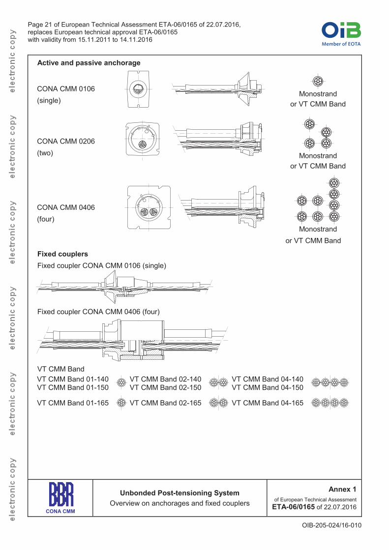
Active and passive anchorage
CONA CMM 0106(single)
Monostrandor VT CMM Band
CONA CMM 0206(two) Monostrand
or VT CMM Band
CONA CMM 0406(four)
Monostrandor VT CMM Band
Fixed couplersFixed coupler CONA CMM 0106 (single)
Fixed coupler CONA CMM 0406 (four)
VT CMM BandVT CMM Band 01-140VT CMM Band 01-150
VT CMM Band 02-140VT CMM Band 02-150
VT CMM Band 04-140VT CMM Band 04-150
VT CMM Band 01-165 VT CMM Band 02-165 VT CMM Band 04-165
CONA CMM
Unbonded Post-tensioning SystemOverview on anchorages and fixed couplers
Annex 1of European Technical Assessment
ETA-06/0165 of 22.07.2016
Page 22 of European Technical Assessment ETA-06/0165 of 22.07.2016,replaces European technical approval ETA-06/0165 with validity from 15.11.2011 to 14.11.2016
OIB-205-024/16-010
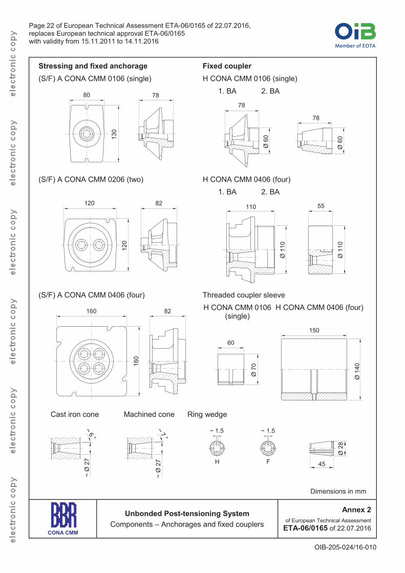
Stressing and fixed anchorage Fixed coupler(S/F) A CONA CMM 0106 (single) H CONA CMM 0106 (single)
80
130
78 1. BA 2. BA
78
Ø 6
0
78
Ø 6
0
(S/F) A CONA CMM 0206 (two) H CONA CMM 0406 (four)
120
120
82
1. BA 2. BA
110
Ø 1
10
55
Ø 1
10
(S/F) A CONA CMM 0406 (four) Threaded coupler sleeve
160
160
82 H CONA CMM 0106 (single)
H CONA CMM 0406 (four)
60
Ø 7
0
150
Ø 1
40
Cast iron cone Machined cone Ring wedge
~ Ø
27
~ Ø
27 H
~ 1.5
F
~ 1.5
Ø 2
8
45
Dimensions in mm
CONA CMM
Unbonded Post-tensioning SystemComponents – Anchorages and fixed couplers
Annex 2of European Technical Assessment
ETA-06/0165 of 22.07.2016
Page 23 of European Technical Assessment ETA-06/0165 of 22.07.2016,replaces European technical approval ETA-06/0165 with validity from 15.11.2011 to 14.11.2016
OIB-205-024/16-010
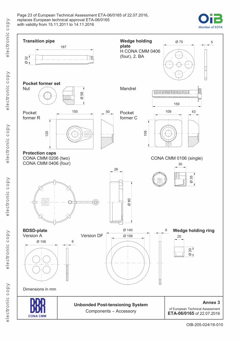
Transition pipe
Ø 3
2
187Wedge holding plateH CONA CMM 0406 (four), 2. BA
Ø 75 5
Pocket former setNut
Ø 5
8
Mandrel
159
Pocket former R
150 50
120
Pocket former C
109
109 43
Protection capsCONA CMM 0206 (two)CONA CMM 0406 (four)
Ø 8
0
26
CONA CMM 0106 (single)
Ø 3
5
30
BDSD-plateVersion A
Ø 106 6Version DF
Ø 140 6Ø 106
Wedge holding ring20
Ø 2
0
Dimensions in mm
CONA CMM
Unbonded Post-tensioning SystemComponents – Accessory
Annex 3of European Technical Assessment
ETA-06/0165 of 22.07.2016
Page 24 of European Technical Assessment ETA-06/0165 of 22.07.2016,replaces European technical approval ETA-06/0165 with validity from 15.11.2011 to 14.11.2016
OIB-205-024/16-010
Material specifications
Component Standard / Specification
Anchor head 0106, 0206, 0406 EN 1563
Coupler anchor head 0106, 0406 – 1. BA EN 1563
Coupler anchor head 0106 – 2. BAEN 1563EN 10083-1EN 10083-2
Coupler anchor head 0406 – 2. BA EN 10083-1EN 10083-2
Coupler sleeve 0106, 0406 EN 10210-1
Ring wedgeHF
EN 10277-2EN 10084
Wedge holding plate EN 10025-2
Helix Ribbed reinforcing steel, Re 500 MPa
Additional reinforcement (stirrups) Ribbed reinforcing steel, Re 500 Mpa
Corrosion protection filling material ETAG 013, Annex C
Strand sheathing ETAG 013, Annex C
Transition pipe EN ISO 16396-1EN ISO 17855-1
Wedge holding ring, protection cap, pocket former set EN ISO 17855-1
BDSD-plate ―
CONA CMM
Unbonded Post-tensioning SystemMaterial specifications
Annex 4of European Technical Assessment
ETA-06/0165 of 22.07.2016
Page 25 of European Technical Assessment ETA-06/0165 of 22.07.2016,replaces European technical approval ETA-06/0165 with validity from 15.11.2011 to 14.11.2016
OIB-205-024/16-010
7-wire strands according to prEN 10138-3 1)
Steel designation Y1770S7 Y1860S7 Y1770S7 Y1860S7 Y1820S7G
Tensile strength Rm MPa 1 770 1 860 1 770 1 860 1 820
Diameter d mm 15.3 15.3 15.7 15.7 15.2 2)
Nominal cross-sectional area Ap mm2 140 140 150 150 165
Nominal mass per metre M kg/m 1.093 1.172 1.289
Permitted deviation from nominal mass % 2
Characteristic value of maximum force Fpk kN 248 260 266 279 300
Maximum value of maximum force Fm, max kN 285 299 306 321 345
Characteristic value of 0.1 % proof force 3) Fp0.1 kN 218 229 234 246 264
Minimum elongation at maximum force, L0 500 mm
Agt % 3.5
Modulus of elasticity Ep MPa 195 000 4)
1) Suitable strands according to standards and regulations valid at the place of use may also be used.2) Compacted strand3) For strands according to prEN 10138-3, 09.2000, the value shall be multiplied by 0.98.4) Standard value
CONA CMM
Unbonded Post-tensioning SystemStrand specifications
Annex 5of European Technical Assessment
ETA-06/0165 of 22.07.2016
Page 26 of European Technical Assessment ETA-06/0165 of 22.07.2016,replaces European technical approval ETA-06/0165 with validity from 15.11.2011 to 14.11.2016
OIB-205-024/16-010
CONA CMM n06-140
Number of strands
Nominal cross-sectional area of prestressing steel
Nominal mass of prestressing steel
Nominal mass of tendon
Characteristic value of maximum force of tendon
fpk = 1 770 MPa fpk = 1 860 MPa
n Ap M M Fpk Fpk
― mm2 kg/m kg/m kN kN
01 140 1.09 1.23 248 260
02 280 2.19 2.46 496 520
04 560 4.37 4.92 992 1 040
CONA CMM n06-150
Number of strands
Nominal cross-sectional area of prestressing steel
Nominal mass of prestressing steel
Nominal mass of tendon
Characteristic value of maximum force of tendon
fpk = 1 770 MPa fpk = 1 860 MPa
n Ap M M Fpk Fpk
― mm2 kg/m kg/m kN kN
01 150 1.17 1.31 266 279
02 300 2.34 2.62 532 558
04 600 4.69 5.24 1 064 1 116
CONA CMM n06C-165, Compacted strand
Number of strands
Nominal cross-sectional area of prestressing steel
Nominal mass of prestressing steel
Nominal mass of tendon
Characteristic value of maximum force of tendon
fpk = 1 820 MPa
n Ap M M Fpk
― mm2 kg/m kg/m kN
01 165 1.29 1.42 300
02 300 2.58 2.84 600
04 660 5.16 5.68 1 200
CONA CMM
Unbonded Post-tensioning SystemTendon ranges
Annex 6of European Technical Assessment
ETA-06/0165 of 22.07.2016
Page 27 of European Technical Assessment ETA-06/0165 of 22.07.2016,replaces European technical approval ETA-06/0165 with validity from 15.11.2011 to 14.11.2016
OIB-205-024/16-010
Maximum prestressing and overstressing forces
CONA CMM 0106 (single)
Strands AP mm2 140 150 1651)
Characteristic tensile strength fpk MPa 1 770 1 860 1 770 1 860 1 820
Characteristic value of maximum force of tendon Fpk kN 248 260 266 279 300
Maximum prestressing force 2) 0.90 ∙ Fp0.1 kN 196 206 211 221 238
Maximum overstressing force 2), 3) 0.95 ∙ Fp0.1 kN 207 218 222 234 251
CONA CMM 0206 (two)
Strands AP mm2 140 150 165 1)
Characteristic tensile strength fpk MPa 1 770 1 860 1 770 1 860 1 820
Characteristic value of maximum force of tendon Fpk kN 496 520 532 558 600
Maximum prestressing force 2) 0.90 ∙ Fp0.1 kN 392 412 421 443 475
Maximum overstressing force 2), 3) 0.95 ∙ Fp0.1 kN 414 435 445 467 502
CONA CMM 0406 (four)
Strands AP mm2 140 150 165 1)
Characteristic tensile strength fpk MPa 1 770 1 860 1 770 1 860 1 820
Characteristic value of maximum force of tendon Fpk kN 992 1 040 1 064 1 116 1 200
Maximum prestressing force 2) 0.90 ∙ Fp0.1 kN 785 824 842 886 950
Maximum overstressing force 2), 3) 0.95 ∙ Fp0.1 kN 828 870 889 935 1 0031) Compacted strand2) The given value are maximum values according to Eurocode 2. The actual values are to be taken from
the standards and regulations in force at the place of use. Conformity with the stabilisation and crack width criteria in the load transfer test has been verified to a level of 0.80 ∙ Fpk.Where Fpk ................. Characteristic value of maximum force of tendon
Fp0.1 ............... Characteristic value of 0.1 % proof force of tendonFor strands according to prEN 10138-3, 09.2000, the value shall be multiplied by 0.98.
3) Overstressing is permitted if the force in the prestressing jack can be measured to an accurancy of ± 5 %of the final value of the prestressing force.
CONA CMM
Unbonded Post-tensioning SystemMaximum prestressing and overstressing forces
Annex 7of European Technical Assessment
ETA-06/0165 of 22.07.2016
Page 28 of European Technical Assessment ETA-06/0165 of 22.07.2016,replaces European technical approval ETA-06/0165 with validity from 15.11.2011 to 14.11.2016
OIB-205-024/16-010
Stressing and fixed anchorage / coupler
Y
Ø A
F
B
E
M
1. BA1st construction stage
2. BA2nd construction stage
BDSD-plate
Centre and edge distance
ae ac
b eb c
ae ac
b eb c
ar
b r
Technical data of the BBR VT CONA CMM anchorage systemCONA CMM 1) 0106 (single) 0206 (two) 0406 (four)Strands AP mm2 140 150 165 140 150 165 140 150 165Char. tensile strength fpk MPa 1 770 1 860 1 770 1 860 1 820 1 770 1 860 1 770 1 860 1 820 1 770 1 860 1 770 1 860 1 820Char. value of maximum force Fpk kN 248 260 266 279 300 496 520 532 558 600 992 1040 1064 1116 1200
0.90 Fp0.1k2) kN 196 206 211 221 238 392 412 421 443 475 785 824 842 886 950
0.95 Fp0.1k2) kN 207 218 222 234 251 414 435 445 467 502 828 870 889 935 1003
Dimensions of strands /band mm Ø20 2 20 / 44 20 4 20 / 90 20
Minimum concrete strengthCube fcm, 0 MPa ≥ 24Cylinder fcm, 0 MPa ≥ 20Helix - The anchorage sided end is welded Ribbed reinforcing steel, Re ≥ 500 MPa
Outer diameter mm 100 160Bar diameter mm 10 12Length, approx. mm 180 275Pitch mm 40 50Number of pitches ― 4+1 5+1Distance E mm 50 45Additional reinforcement Ribbed reinforcing steel, Re ≥ 500 MPaNumber of stirrups ― 2 4 6Bar diameter mm 8 10 10Spacing Y mm 50 50 55Distance from anchor plate F mm 55 25 53
Outside dimensions ar mm 140 180 260br mm 100 130 180
Centre and edge spacingMinimum centre spacing
ac mm 180 200 300bc mm 140 150 220
Minimum edge distance
ae mm 70 + c 90 + c 130 + cbe mm 50 + c 65 + c 90 + c
Bore in forms ØA mm 65 103 103Bore in forms for coupler 1. BA ØA mm 62 — 113
Depth B mm 50 50 50Coupler M mm ~ 545 — ~ 5651) For strand pattern see Annex 2.2) For strands according to prEN 10138-3, 09.2000, the values shall be multiplied by 0.98.3) c .......Concrete cover
CONA CMM
Unbonded Post-tensioning SystemDimensions of anchorages, helix and additional
reinforcement, centres spacing and edge distance
Annex 8of European Technical Assessment
ETA-06/0165 of 22.07.2016
Page 29 of European Technical Assessment ETA-06/0165 of 22.07.2016,replaces European technical approval ETA-06/0165 with validity from 15.11.2011 to 14.11.2016
OIB-205-024/16-010
Centre spacing and edge distance
b eb c
ae ac
c
c
b eb c
ae ac
c
ca'e
b' e
a'e_
b' e_ac, bc
ae, be
ac bc
ae be
Modification of centre spacing and edge distance in accordance with the Clauses 1.7 and 2.2.3.4.
bc_
0.85 bcand
Helix, outside diameter 1)
ac_Ac
bc_
Ac = ac · bc ac_ · bc_
Corresponding edge distances
ae– =ac–
2 10 mm + c
and
be– =bc–
2 10 mm + c
c .....Concrete cover1).....The outer dimensions of the additional reinforcement are adjusted accordingly. Further modifications of
reinforcement have to be in accordance with Clause 2.2.3.4.
CONA CMM
Unbonded Post-tensioning SystemAnchorage zone – Dimensions
Modification of centre spacing and edge distance
Annex 9of European Technical Assessment
ETA-06/0165 of 22.07.2016
Page 30 of European Technical Assessment ETA-06/0165 of 22.07.2016,replaces European technical approval ETA-06/0165 with validity from 15.11.2011 to 14.11.2016
OIB-205-024/16-010
Construction examples, minimised anchorage recess dimensionsTendon CONA CMM 0106 (single)Strand excess length 70 cm supposed 2 cm concrete cover
20 585(B) 5
13
13
18 9
147
90 °
Tendon CONA CMM 0206 (two)Strand excess length 40 cm
20 60
8(B) 5
16
16
20 1115
9
Tendon CONA CMM 0406 (four)Strand excess length 40 cm
20 61
9
(B) 5
18
18
30 15
2211
If other prestressing jacks will be used, different minimum dimensions may apply. Ask ETA holder for advice.
Dimensions in cm
CONA CMM
Unbonded Post-tensioning SystemDimensions of anchorage recesses
Annex 10of European Technical Assessment
ETA-06/0165 of 22.07.2016
Page 31 of European Technical Assessment ETA-06/0165 of 22.07.2016,replaces European technical approval ETA-06/0165 with validity from 15.11.2011 to 14.11.2016
OIB-205-024/16-010
Free tendon layout
anchorage
≤ 45
0 reinforcementCrosswise racking (wire) with
protection sleeve or equivalent anchorage
Crosswise racking (wire) withprotection sleeve or equivalent
crosswise racking (wire) withprotection sleeve or equivalent
Single racking(wire or plastic binder)
AL LL LL LH HH HH HA
Typical zones max. distances min. number Racking
AL Anchorage – Low point 3 m ― Crosswise
LL Low point – Low point 1.0–1.3 m 2 Single wire
LH Low point – High point 3 m ― Crosswise
HH High point – High point 0.3–1.0 m 2 Crosswise
HA High point – Anchorage 1.5 m ― Crosswise
Transition regionsTendon CONA CMM 0206 (two)
Transition region ≥ 1 000~ 270
AA
BB
200
Section A-A Section B-B
Monostrand VT CMM Bandor
≥ 20 ≥ 20
≥ 90Tendon CONA CMM 0406 (four)
Transition region ≥ 1 000~ 270
AA
BB
Section A-A Section B-B
Monostrand VT CMM Bandor
≥ 20 ≥ 20
≥ 90
Dimensions in mm
CONA CMM
Unbonded Post-tensioning SystemFree tendon layout – Transition regions
Annex 11of European Technical Assessment
ETA-06/0165 of 22.07.2016
Page 32 of European Technical Assessment ETA-06/0165 of 22.07.2016,replaces European technical approval ETA-06/0165 with validity from 15.11.2011 to 14.11.2016
OIB-205-024/16-010
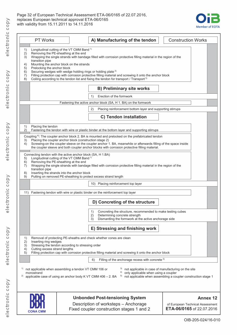
PT Works A) Manufacturing of the tendon Construction Works
1) Longitudinal cutting of the VT CMM Band 1)
2) Removing the PE-sheathing at the end3) Wrapping the single strands with bandage filled with corrosion protective filling material in the region of the
transition pipe4) Mounting the anchor block on the strands5) Prelocking the anchor block6) Securing wedges with wedge holding rings or holding plate 2)
7) Filling protection cap with corrosion protective filling material and screwing it onto the anchor block8) Coiling according to the tendon list and fixing the tendon for transport / Transport 3)
B) Preliminary site works1) Erection of the formwork
Fastening the active anchor block (SA, H 1. BA) on the formwork
2) Placing reinforcement bottom layer and supporting stirrups
C) Tendon installation
1) Placing the tendon2) Fastening the tendon with wire or plastic binder at the bottom layer and supporting stirrups
Coupling 4): The coupler anchor block 2. BA is mounted and prelocked on the prefabricated tendon3) Placing the coupler anchor block (construction stage 2)4) Screwing-on the coupler sleeve on the coupler anchor 1. BA, meanwhile or afterwards filling of the space inside
the coupler sleeve and both coupler anchor blocks with corrosion protective filling material.
Connecting tendon with the active anchor block (SA, H 1.BA)5) Longitudinal cutting of the VT CMM Band 1)
6) Removing the PE-sheathing at the end7) Wrapping the single strands with bandage filled with corrosion protective filling material in the region of the
transition pipe8) Inserting the strands into the anchor block9) Putting on removed PE-sheathing to protect excess strand length
10) Placing reinforcement top layer
11) Fastening tendon with wire or plastic binder on the reinforcement top layer
D) Concreting of the structure
1) Concreting the structure, recommended to make testing cubes2) Determining concrete strength3) Dismantling the formwork at the active anchorage side
E) Stressing and finishing work
1) Removal of protecting PE-sheaths and check whether cones are clean2) Inserting ring wedges3) Stressing the tendon according to stressing order4) Cutting excess strand lengths5) Filling protection cap with corrosion protective filling material and screwing it onto the anchor block
6) Filling of the anchorage recess with concrete 5)
1) not applicable when assembling a tendon VT CMM 106 or monostrand
2) applicable case of using an anchor body K VT CMM 406 – 2. BA
3) not applicable in case of manufacturing on the site4) only applicable when using a coupler5) not applicable when assembling a coupler construction stage 1
CONA CMM
Unbonded Post-tensioning SystemDescription of worksteps – Anchorage
Fixed coupler construction stages 1 and 2
Annex 12of European Technical Assessment
ETA-06/0165 of 22.07.2016
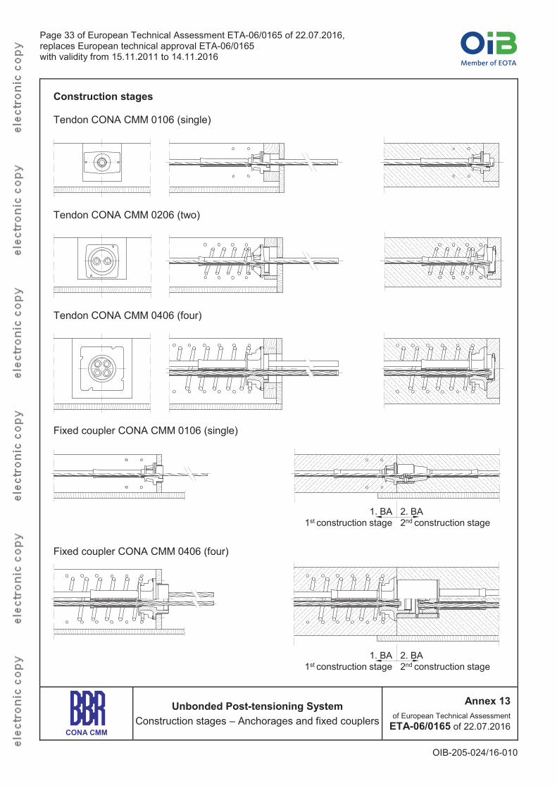
Page 33 of European Technical Assessment ETA-06/0165 of 22.07.2016,replaces European technical approval ETA-06/0165 with validity from 15.11.2011 to 14.11.2016
OIB-205-024/16-010
Construction stages
Tendon CONA CMM 0106 (single)
Tendon CONA CMM 0206 (two)
Tendon CONA CMM 0406 (four)
Fixed coupler CONA CMM 0106 (single)
1. BA1st construction stage
2. BA2nd construction stage
Fixed coupler CONA CMM 0406 (four)
1. BA1st construction stage
2. BA2nd construction stage
CONA CMM
Unbonded Post-tensioning SystemConstruction stages – Anchorages and fixed couplers
Annex 13of European Technical Assessment
ETA-06/0165 of 22.07.2016
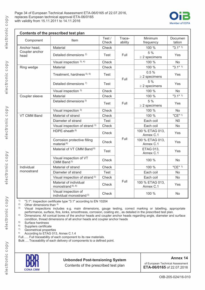
Page 34 of European Technical Assessment ETA-06/0165 of 22.07.2016,replaces European technical approval ETA-06/0165 with validity from 15.11.2011 to 14.11.2016
OIB-205-024/16-010
Contents of the prescribed test plan
Component Item Test / Check
Trace-ability
Minimum frequency
Documentation
Anchor head, Coupler anchor head
Material Check
Full
100 % "3.1" 1)
Detailed dimensions 2) Test 5 %2 specimens Yes
Visual inspection 3), 4) Check 100 % NoRing wedge Material Check
Full
100 % "3.1" 1)
Treatment, hardness 5), 6) Test 0.5 %2 specimens Yes
Detailed dimensions 7) Test 5 %2 specimens Yes
Visual inspection 3) Check 100 % NoCoupler sleeve Material Check
Full
100 % "3.1" 1)
Detailed dimensions 2)Test 5 %
2 specimens Yes
Visual inspection 3) Check 100 % NoVT CMM Band Material of strand Check
Full
100 % "CE" 1)
Diameter of strand Test Each coil N0Visual inspection of strand 3) Check Each coil NoHDPE-sheath 6)
Check 100 % ETAG 013, Annex C.1 Yes
Corrosion protective filling material 6) Check 100 % ETAG 013,
Annex C.1 Yes
Material of VT CMM Band 8)Test ETAG 013,
Annex C.1 Yes
Visual inspection of VT CMM Band 3) Check 100 % No
Individual monostrand
Material of strand Check
Full
100 % "CE" 1)
Diameter of strand Test Each coil NoVisual inspection of strand 3) Check Each coil NoMaterial of individual monostrand 6), 8) Check 100 % ETAG 013,
Annex C.1 Yes
Visual inspection of individual monostrand 3) Check 100 % No
1) "3.1": Inspection certificate type "3.1" according to EN 102042) Other dimensions than 4)
3) Visual inspections includes e.g. main dimensions, gauge testing, correct marking or labelling, appropriate performance, surface, fins, kinks, smoothness, corrosion, coating etc., as detailed in the prescribed test plan.
4) Dimensions: All conical bores of the anchor heads and coupler anchor heads regarding angle, diameter and surface condition, thread dimensions of all anchor heads and coupler anchor heads
5) Surface hardness6) Suppliers certificate7) Geometrical properties8) According to ETAG 013, Annex C.1.4Full...... Full traceability of each component to its raw materials. Bulk .... Traceability of each delivery of components to a defined point.
CONA CMM
Unbonded Post-tensioning SystemContents of the prescribed test plan
Annex 14of European Technical Assessment
ETA-06/0165 of 22.07.2016
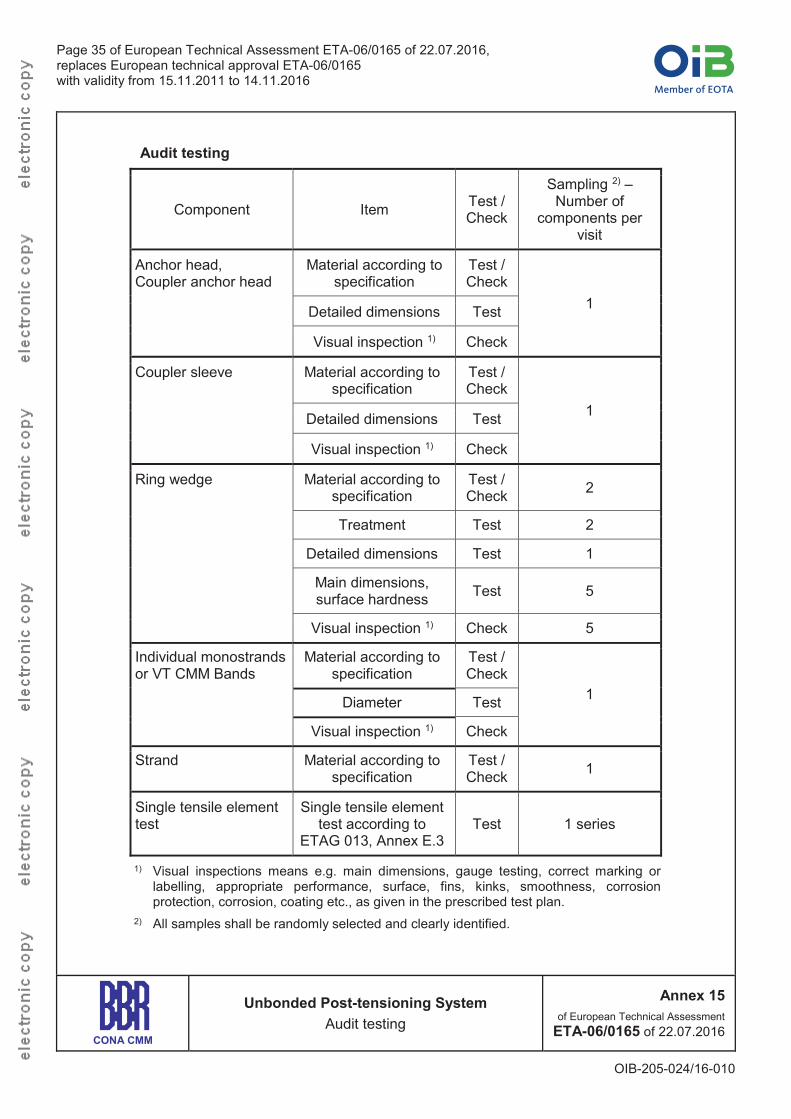
Page 35 of European Technical Assessment ETA-06/0165 of 22.07.2016,replaces European technical approval ETA-06/0165 with validity from 15.11.2011 to 14.11.2016
OIB-205-024/16-010
Audit testing
Component Item Test / Check
Sampling 2) –Number of
components per visit
Anchor head, Coupler anchor head
Material according to specification
Test / Check
1Detailed dimensions Test
Visual inspection 1) Check
Coupler sleeve Material according to specification
Test / Check
1Detailed dimensions Test
Visual inspection 1) Check
Ring wedge Material according to specification
Test / Check 2
Treatment Test 2
Detailed dimensions Test 1
Main dimensions, surface hardness Test 5
Visual inspection 1) Check 5
Individual monostrands or VT CMM Bands
Material according to specification
Test / Check
1Diameter Test
Visual inspection 1) Check
Strand Material according to specification
Test / Check 1
Single tensile element test
Single tensile element test according to
ETAG 013, Annex E.3Test 1 series
1) Visual inspections means e.g. main dimensions, gauge testing, correct marking or labelling, appropriate performance, surface, fins, kinks, smoothness, corrosion protection, corrosion, coating etc., as given in the prescribed test plan.
2) All samples shall be randomly selected and clearly identified.
CONA CMM
Unbonded Post-tensioning SystemAudit testing
Annex 15of European Technical Assessment
ETA-06/0165 of 22.07.2016
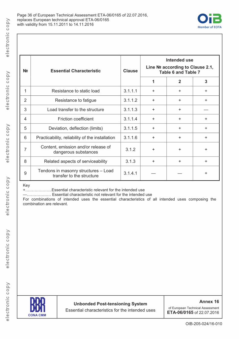
Page 36 of European Technical Assessment ETA-06/0165 of 22.07.2016,replaces European technical approval ETA-06/0165 with validity from 15.11.2011 to 14.11.2016
OIB-205-024/16-010
№ Essential Characteristic Clause
Intended useLine № according to Clause 2.1,
Table 6 and Table 7
1 2 3
1 Resistance to static load 3.1.1.1 + + +
2 Resistance to fatigue 3.1.1.2 + + +
3 Load transfer to the structure 3.1.1.3 + + —
4 Friction coefficient 3.1.1.4 + + +
5 Deviation, deflection (limits) 3.1.1.5 + + +
6 Practicability, reliability of the installation 3.1.1.6 + + +
7 Content, emission and/or release of dangerous substances 3.1.2 + + +
8 Related aspects of serviceability 3.1.3 + + +
9 Tendons in masonry structures – Load transfer to the structure 3.1.4.1 — — +
Key+………………..Essential characteristic relevant for the intended use—……………… Essential characteristic not relevant for the intended useFor combinations of intended uses the essential characteristics of all intended uses composing the combination are relevant.
CONA CMM
Unbonded Post-tensioning SystemEssential characteristics for the intended uses
Annex 16of European Technical Assessment
ETA-06/0165 of 22.07.2016
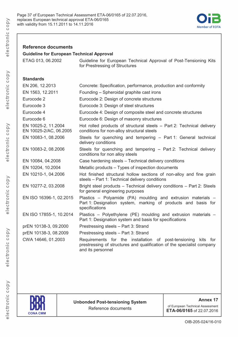
Page 37 of European Technical Assessment ETA-06/0165 of 22.07.2016,replaces European technical approval ETA-06/0165 with validity from 15.11.2011 to 14.11.2016
OIB-205-024/16-010
Reference documentsGuideline for European Technical ApprovalETAG 013, 06.2002 Guideline for European Technical Approval of Post-Tensioning Kits
for Prestressing of Structures
StandardsEN 206, 12.2013 Concrete: Specification, performance, production and conformityEN 1563, 12.2011 Founding – Spheroidal graphite cast ironsEurocode 2 Eurocode 2: Design of concrete structures Eurocode 3 Eurocode 3: Design of steel structuresEurocode 4 Eurocode 4: Design of composite steel and concrete structuresEurocode 6 Eurocode 6: Design of masonry structuresEN 10025-2, 11.2004 EN 10025-2/AC, 06.2005
Hot rolled products of structural steels – Part 2: Technical delivery conditions for non-alloy structural steels
EN 10083-1, 08.2006 Steels for quenching and tempering – Part 1: General technical delivery conditions
EN 10083-2, 08.2006 Steels for quenching and tempering – Part 2: Technical delivery conditions for non alloy steels
EN 10084, 04.2008 Case hardening steels – Technical delivery conditionsEN 10204, 10.2004 Metallic products – Types of inspection documentsEN 10210-1, 04.2006 Hot finished structural hollow sections of non-alloy and fine grain
steels – Part 1: Technical delivery conditionsEN 10277-2, 03.2008 Bright steel products – Technical delivery conditions – Part 2: Steels
for general engineering purposesEN ISO 16396-1, 02.2015 Plastics – Polyamide (PA) moulding and extrusion materials –
Part 1: Designation system, marking of products and basis for specifications
EN ISO 17855-1, 10.2014 Plastics – Polyethylene (PE) moulding and extrusion materials –Part 1: Designation system and basis for specifications
prEN 10138-3, 09.2000 Prestressing steels – Part 3: StrandprEN 10138-3, 08.2009 Prestressing steels – Part 3: StrandCWA 14646, 01.2003 Requirements for the installation of post-tensioning kits for
prestressing of structures and qualification of the specialist company and its personnel
CONA CMM
Unbonded Post-tensioning SystemReference documents
Annex 17of European Technical Assessment
ETA-06/0165 of 22.07.2016

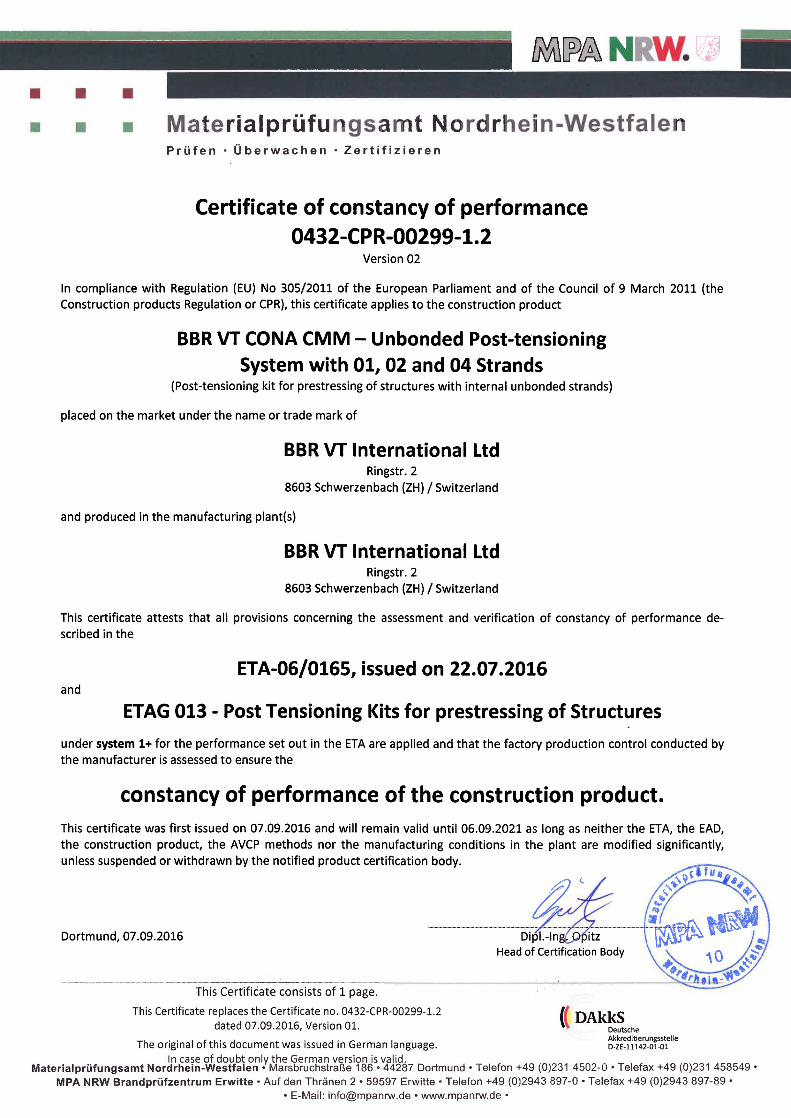
BBR VT International LtdTechnical Headquarters and Business Development CentreSwitzerland
Cop
yrig
ht B
BR
VT
Inte
rnat
iona
l 09.
2016
KB Vorspann-Technik GmbH Weitwörth 25 5151 Nussdorf a. H. Austria
Tel +43 6272 40790 Fax +43 6272 40790 11
www.kb-vt.com [email protected]
KB Vorspann-Technik GmbH Bahnhofstrasse 108 82166 Gräfelfing Germany
Tel +49 89 724 49 69 0 Fax +49 89 724 49 69 12
www.kb-vt.com [email protected]