Embed Size (px)
Citation preview

Proceedings of Acoustics 2012 - Fremantle 21-23 November 2012, Fremantle, Australia
Australian Acoustical Society 1
Unattended noise monitoring: how to to fulfill IEC 61672 sound level meter standard for 0 degree and 90 degree
reference directions with the same device
Patrice PISCHEDDA (1), Erik AFLALO (2) (1) ACOEM, Office Unit C 712, Lufthansa Center, N°50 Liangmaqiao Road, Chaoyang District,
Beijing 100125 CHINA
(2) ACOEM, 200 Chemin des Ormeaux, F-69578 Limonest FRANCE
ABSTRACT Unattended noise measurements are more and more common for noise assessment in the environment. Multiple
sources are usually measured with a random position with respect to the measurement point. Noise generated by ground transportation, leisure activities, construction sites is coming from all directions, although mainly the horizon-
tal direction. Placed vertically and configured for a reference direction of 90° from its axis, the goal is to meet the re-
quirements of the IEC 61672 standard on sound level meters taking into account noise incidence from the horizontal direction. The main technical difficulty is the criterion for the maximum level difference allowed between two ran-
dom incidence angles (directivity). The objective can be fulfilled using a cone-shaped device on top of the micro-
phone. When measuring attended noise with the instrument in hand, the sound level meter must be pointed at the
source according to standard IEC 60651. The purpose of the paper is to describe the different research &development phases to fulfill IEC 61672 sound level meter standard for 0° and 90° reference directions with the same device.
INTRODUCTION
For sound level measurements performed in accordance with
IEC 61672 [1], the sound level meter is supposed to be point-ed towards the source (0° incidence).
For unattended measurements, the direction from the source
is generally unknown. Except for aircraft noise measure-ments, the sources are located on the ground, see Figure 1;
therefore the optimal position for unattended noise measure-
ments is to setup the measurement device vertically and to
design it in such a way that it fulfills the IEC 61672-1 stand-ard for ground sources (90° incidence):
Figure 1. Ground sources and sound level meter orientation
for 90° incidence.
Our goal was to achieve a sound level meter design able to fulfill both 0° (for aircraft noise [2] and measurement point-
ing at the source) and 90° reference directions (for unattend-
ed measurements on ground sources).
DESIGN CONSTRAINTS
IEC 61672-1: directional response limits
Table 1 gives directional response requirements for the con-figuration of a sound level meter as stated in the instruction
manual for the normal mode of operation. The specifications
in Table 1 apply for plane progressive sound waves at any sound-incidence angle within the indicated ranges, including
the reference direction. At any frequency, the design goal is
equal response to sounds from all directions of sound inci-
dence (§ 5.3 of IEC 61672-1 standard).
Table 1. Maximum absolute difference in displayed sound
levels for class 1 at any two sound-incidence angles within
±θ degrees from the reference direction (extended by the expanded uncertainty of measurement for demonstration of
compliance to the limits given below).
Frequency
[kHz]
Expanded
uncertainty
[dB]
θ = 30° θ = 90° θ = 150°
0.25 to 1 0.3 1.3 dB 1.8 dB 2.3 dB
> 1 to 2 0.5 1.5 dB 2.5 dB 4.5 dB
>2 to 4 0.5 2.0 dB 4.5 dB 6.5 dB
>4 to 8 1.0 3.5 dB 8.0 dB 11.0 dB
>8 to 12.5 1.5 5.5 dB 11.5 dB 15.5 dB
Paper Peer Reviewed

21-23 November 2012, Fremantle, Australia Proceedings of Acoustics 2012 - Fremantle
2 Australian Acoustical Society
Condenser microphones behavior at high frequen-cies; Limitations due to diameter
High frequency response depends on the diameter of the diaphragm, see Figure 2 and Figure 3:
Figure 2. Influence of propagation on a microphone for a 90° incident wave.
-50
-40
-30
-20
-10
0
10
20
1000 10000 100000 1000000
Frequency (Hz)
SP
L (d
B),
re
. 4
0D
P &
90
de
g
40AG &
90deg
40BP &
90deg
40DP &
90deg
Figure 3. Influence of the microphone diameter on the fre-
quency response (90° incidence) for 1/2" (red), 1/4" (green)
and 1/8" (blue) microphones.
The frequency response is improved when the diameter of the
diaphragm decreases.
Nevertheless the positive effect is altered by a higher back-ground noise (thermal noise), see Table 2:
Table 2. Typical characteristics for different microphone
diaphragm diameters
Microphone dia-
phragm diameter
1/2" 1/4" 1/8"
Sensitivity (typical) 50 mV/Pa 4 mV/Pa 1 mV/Pa
Thermal noise
(typical)
15 dBA 30 dBA 40 dBA
1/2" microphones are usually selected, as being the best
compromise between costs, frequency response and back-ground noise for general environmental noise assessment.
Focus on 1/2" microphones
0
0,5
1
1,5
2
2,5
3
3,5
4
4,5
5
1000 10000
±30°
Figure 4. Directional response (green) of a 1/2" microphone for θ = 30° (reference direction 90°). Tolerance values of IEC
61672-1 (red) without expanded uncertainty.
Standards 1/2" microphones do not fulfil IEC standard (direc-tional response) for the reference direction 90° configuration.
The directional response (maximum absolute difference in
displayed sound levels for class 1 at any two sound-incidence angles within ±30°, 90° and 150°) is out of tolerance.
SOLUTION: ACOUSTIC CONE
Shape of DUO sound level meter body and distance of the microphone to the body
Various shapes of the mechanical design of DUO [3] at the early stage, as well as several distances between the micro-
phone and the body were made and tested using 3D prints;
see Figure 5 and Figure 6:
Figure 5. Different shapes for the upper part of the DUO
sound level meter body tested for optimum frequency re-sponse and directional response.
Figure 6. Electro acoustic tests performed on 3D prints to validate the mechanical design of the body.
Proceedings of Acoustics 2012 - Fremantle 21-23 November 2012, Fremantle, Australia
Australian Acoustical Society 3
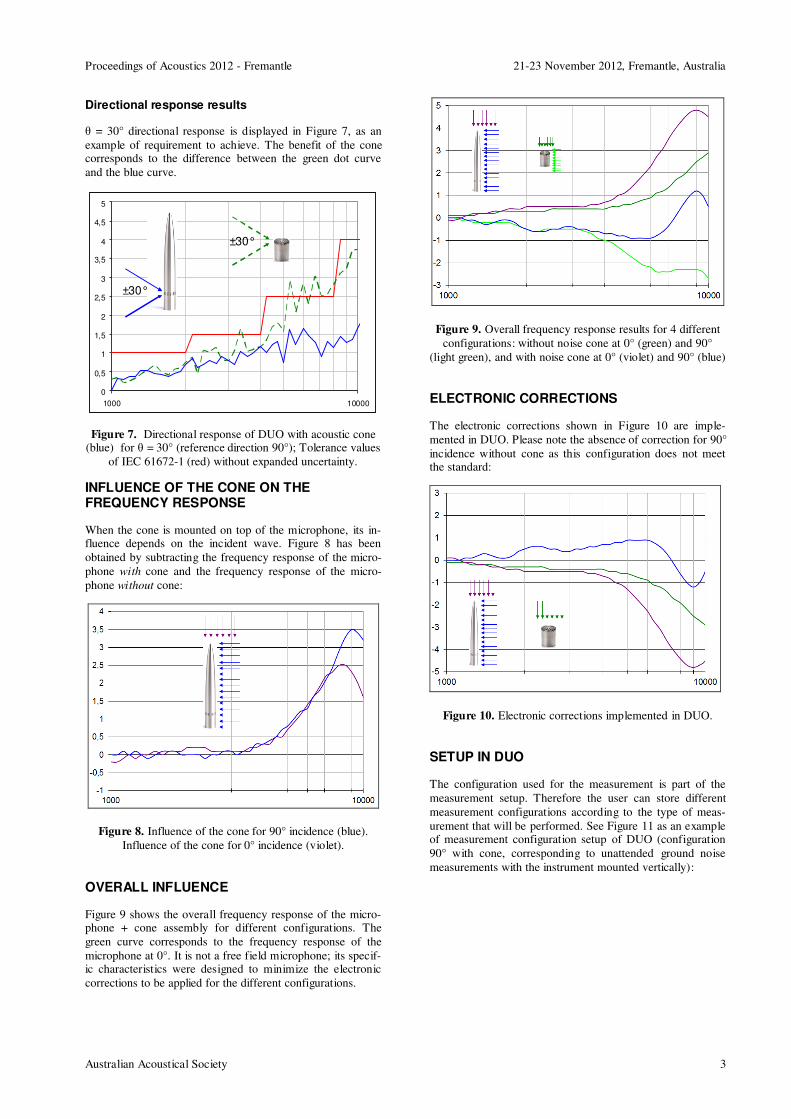
Directional response results
θ = 30° directional response is displayed in Figure 7, as an
example of requirement to achieve. The benefit of the cone corresponds to the difference between the green dot curve
and the blue curve.
0
0,5
1
1,5
2
2,5
3
3,5
4
4,5
5
1000 10000
±30°
±30°
Figure 7. Directional response of DUO with acoustic cone (blue) for θ = 30° (reference direction 90°); Tolerance values
of IEC 61672-1 (red) without expanded uncertainty.
INFLUENCE OF THE CONE ON THE FREQUENCY RESPONSE
When the cone is mounted on top of the microphone, its in-fluence depends on the incident wave. Figure 8 has been
obtained by subtracting the frequency response of the micro-
phone with cone and the frequency response of the micro-
phone without cone:
Figure 8. Influence of the cone for 90° incidence (blue).
Influence of the cone for 0° incidence (violet).
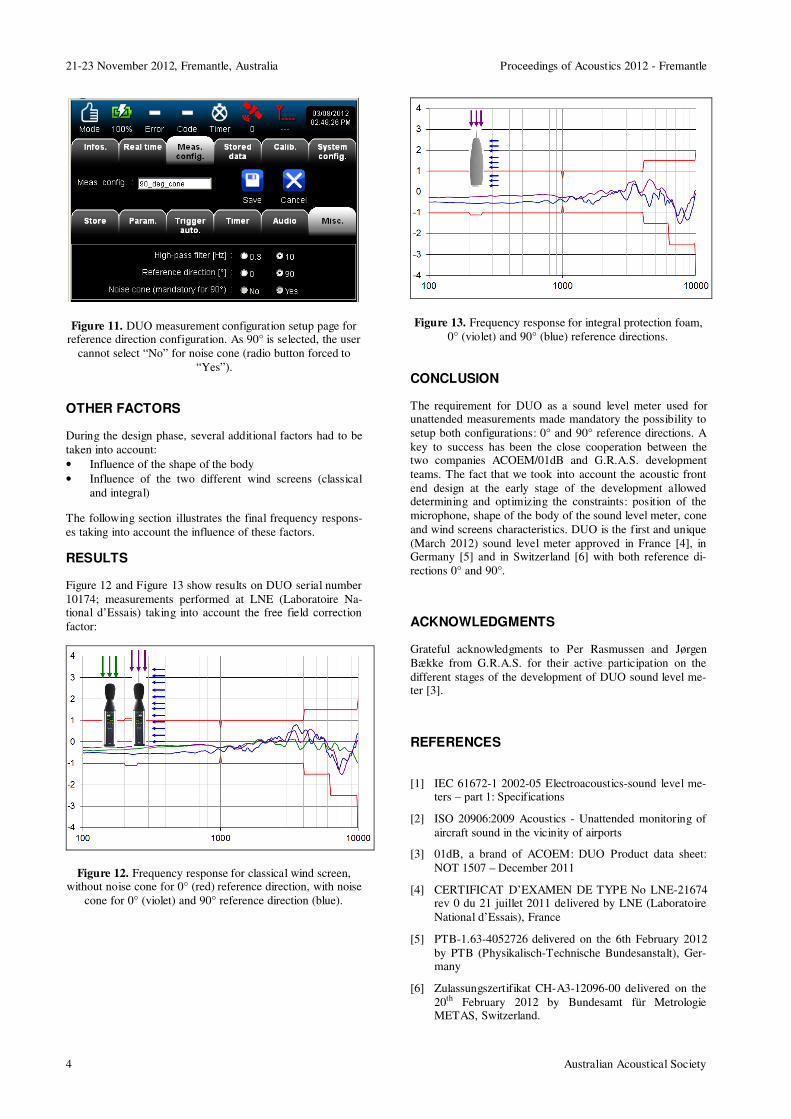
OVERALL INFLUENCE
Figure 9 shows the overall frequency response of the micro-phone + cone assembly for different configurations. The
green curve corresponds to the frequency response of the
microphone at 0°. It is not a free field microphone; its specif-ic characteristics were designed to minimize the electronic
corrections to be applied for the different configurations.
Figure 9. Overall frequency response results for 4 different
configurations: without noise cone at 0° (green) and 90°
(light green), and with noise cone at 0° (violet) and 90° (blue)
ELECTRONIC CORRECTIONS
The electronic corrections shown in Figure 10 are imple-
mented in DUO. Please note the absence of correction for 90°
incidence without cone as this configuration does not meet the standard:
Figure 10. Electronic corrections implemented in DUO.
SETUP IN DUO
The configuration used for the measurement is part of the
measurement setup. Therefore the user can store different
measurement configurations according to the type of meas-
urement that will be performed. See Figure 11 as an example of measurement configuration setup of DUO (configuration
90° with cone, corresponding to unattended ground noise
measurements with the instrument mounted vertically):
21-23 November 2012, Fremantle, Australia Proceedings of Acoustics 2012 - Fremantle
4 Australian Acoustical Society
Figure 11. DUO measurement configuration setup page for reference direction configuration. As 90° is selected, the user
cannot select “No” for noise cone (radio button forced to
“Yes”).
OTHER FACTORS
During the design phase, several additional factors had to be
taken into account:
• Influence of the shape of the body
• Influence of the two different wind screens (classical
and integral)
The following section illustrates the final frequency respons-
es taking into account the influence of these factors.
RESULTS
Figure 12 and Figure 13 show results on DUO serial number
10174; measurements performed at LNE (Laboratoire Na-tional d’Essais) taking into account the free field correction
factor:
Figure 12. Frequency response for classical wind screen, without noise cone for 0° (red) reference direction, with noise
cone for 0° (violet) and 90° reference direction (blue).
Figure 13. Frequency response for integral protection foam,
0° (violet) and 90° (blue) reference directions.
CONCLUSION
The requirement for DUO as a sound level meter used for unattended measurements made mandatory the possibility to
setup both configurations: 0° and 90° reference directions. A
key to success has been the close cooperation between the two companies ACOEM/01dB and G.R.A.S. development
teams. The fact that we took into account the acoustic front
end design at the early stage of the development allowed determining and optimizing the constraints: position of the
microphone, shape of the body of the sound level meter, cone
and wind screens characteristics. DUO is the first and unique
(March 2012) sound level meter approved in France [4], in Germany [5] and in Switzerland [6] with both reference di-
rections 0° and 90°.
ACKNOWLEDGMENTS
Grateful acknowledgments to Per Rasmussen and Jørgen
Bække from G.R.A.S. for their active participation on the
different stages of the development of DUO sound level me-ter [3].
REFERENCES
[1] IEC 61672-1 2002-05 Electroacoustics-sound level me-ters – part 1: Specifications
[2] ISO 20906:2009 Acoustics - Unattended monitoring of
aircraft sound in the vicinity of airports
[3] 01dB, a brand of ACOEM: DUO Product data sheet:
NOT 1507 – December 2011
[4] CERTIFICAT D’EXAMEN DE TYPE No LNE-21674 rev 0 du 21 juillet 2011 delivered by LNE (Laboratoire
National d’Essais), France
[5] PTB-1.63-4052726 delivered on the 6th February 2012
by PTB (Physikalisch-Technische Bundesanstalt), Ger-many
[6] Zulassungszertifikat CH-A3-12096-00 delivered on the
20th February 2012 by Bundesamt für Metrologie METAS, Switzerland.


![is.15575.2.2005 [IEC 61672-2 (2003)] [law.resource.org]](https://img.pdfslide.us/doc/110x75/577cc9b81a28aba711a46e60/is1557522005-iec-61672-2-2003-lawresourceorg.jpg)