Embed Size (px)
Citation preview
Instruction ManualBedienungsanleitungManuel d’utilisationManuale di Istruzioni
UMX™ F4U Corsair
LT.JG. KEPFORDLT.JG. KEPFORD
2
EN
WARNING: Read the ENTIRE instruction manual to become familiar with the features of the
product before operating. Failure to operate the product correctly can result in damage to the product, personal property and cause serious injury.
This is a sophisticated hobby product. It must be operated with caution and common sense and requires some basic mechanical ability. Failure to operate this product in a safe and responsible manner could result in injury or damage to the product or other property. This product is not intended for use by children without direct adult supervision. Do not use with incompatible components or alter this product in any way outside of the instructions provided by Horizon Hobby, LLC. This manual contains instructions for safety, operation and maintenance. It is essential to read and follow all the instructions and warnings in the manual, prior to assembly, setup or use, in order to operate correctly and avoid damage or serious injury.
Safety Precautions and Warnings
• Always keep a safe distance in all directions around your model to avoid collisions or injury. This model is controlled by a radio signal subject to interference from many sources outside your control. Interference can cause momentary loss of control.
• Always operate your model in open spaces away from full-size vehicles, traffi c and people.
• Always carefully follow the directions and warnings for this and any optional support equip-ment (chargers, rechargeable battery packs, etc.).
• Always keep all chemicals, small parts and anything electrical out of the reach of children.
• Always avoid water exposure to all equipment not specifi cally designed and protected for this purpose. Moisture causes damage to electronics.
• Never place any portion of the model in your mouth as it could cause serious injury or even death.
• Never operate your model with low transmitter batteries.
• Always keep aircraft in sight and under control.
• Always use fully charged batteries.
• Always keep the transmitter powered on while aircraft is powered.
• Always remove batteries before disassembly.
• Always keep moving parts clean.
• Always keep parts dry.
• Always let parts cool after use before touching.
• Always remove batteries after use.
• Always ensure failsafe is properly set before fl ying.
• Never operate aircraft with damaged wiring.
• Never touch moving parts.
Age Recommendation: Not for children under 14 years. This is not a toy.
NOTICE
All instructions, warranties and other collateral documents are subject to change at the sole discretion of Horizon Hobby, LLC. For up-to-date product literature, visit www.horizonhobby.com and click on the support tab for this product.
Meaning of Special Language:
The following terms are used throughout the product literature to indicate various levels of potential harm when operating this product:
NOTICE: Procedures, which if not properly followed, create a possibility of physical property damage AND little or no possibility of injury.
CAUTION: Procedures, which if not properly followed, create the probability of physical property damage AND a possibility of serious injury.
WARNING: Procedures, which if not properly followed, create the probability of property damage, collateral damage, and serious injury OR create a high probability of superfi cial injury.
3
EN
Thank you for purchasing the E-fl ite® UMX™ F4U Corsair, featuring trim schemes from two of the most prolifi c pilots to fl y the prized Corsair, Gregory “Pappy” Boyington and Ira “Ike” Kepford. Now featuring
AS3X® technology, the Ultra Micro F4U Corsair provides the smooth, locked-in fl ight performance that makes this bent-wing warbird feel like a much larger model. True to its roots, the ultra micro F4U Corsair is capable of basic aerobatics yet is suitable for small fl ying areas thanks to its size. Before you take the fi rst fl ight, please take time to read through this manual. It has important prefl ight information that will help ensure your fi rst fl ight and every one after is a success.
Please be sure to read through this manual carefully so that you are equipped to successfully enjoy all the benefi ts this outstanding ultra micro model has to offer.
To register your product online, go to www.e-fl iterc.com
12
.8 in
(3
26
mm
)
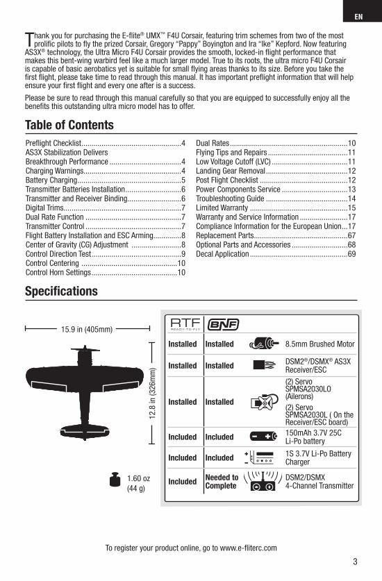
15.9 in (405mm)
1.60 oz
(44 g)
Table of Contents
Specifi cations
Installed Installed 8.5mm Brushed Motor
Installed InstalledDSM2®/DSMX® AS3X Receiver/ESC
Installed Installed
(2) Servo SPMSA2030LO (Ailerons)
(2) Servo SPMSA2030L ( On the Receiver/ESC board)
Included Included150mAh 3.7V 25C Li-Po battery
Included Included1S 3.7V Li-Po Battery Charger
IncludedNeeded to Complete
DSM2/DSMX 4-Channel Transmitter
Prefl ight Checklist ..................................................4AS3X Stabilization Delivers Breakthrough Performance ....................................4Charging Warnings.................................................4Battery Charging ....................................................5Transmitter Batteries Installation ............................6Transmitter and Receiver Binding ...........................6Digital Trims ...........................................................7Dual Rate Function ................................................7Transmitter Control ................................................7Flight Battery Installation and ESC Arming..............8Center of Gravity (CG) Adjustment .........................8Control Direction Test .............................................9Control Centering ................................................10Control Horn Settings ...........................................10
Dual Rates ...........................................................10Flying Tips and Repairs ........................................11Low Voltage Cutoff (LVC) ......................................11Landing Gear Removal .........................................12Post Flight Checklist ............................................12Power Components Service .................................13Troubleshooting Guide .........................................14Limited Warranty .................................................15Warranty and Service Information ........................17Compliance Information for the European Union ...17Replacement Parts ...............................................67Optional Parts and Accessories ............................68Decal Application .................................................69
4
EN
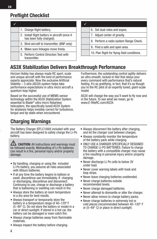
1. Charge fl ight battery.
2. Install fl ight battery in aircraft (once it has been fully charged).
3. Bind aircraft to transmitter. (BNF only)
4. Make sure linkages move freely.
5. Perform Control Direction Test with transmitter.
6. Set dual rates and expos.
7. Adjust center of gravity.
8. Perform a radio system Range Check.
9. Find a safe and open area.
10. Plan fl ight for fl ying fi eld conditions.
Horizon Hobby has always made RC sport, scale and unique aircraft with the kind of performance experts appreciate. Now the exclusive Artificial Stability – 3 aXis (AS3X) system helps take performance expectations in ultra micro aircraft a quantum leap higher.
Based on the successful use of MEMS sensor technology within the AS3X Stabilization System essential to Blade® ultra micro flybarless helicopters, the specifically tuned AS3X System for airplanes helps invisibly correct for turbulence, torque and tip stalls when encountered.
Furthermore, the outstanding control agility delivers an ultra smooth, locked-in feel that obeys your every command with performance that’s natural feeling. It’s so gratifying, in fact, that it’s as though you’re the RC pilot of an expertly tuned, giant-scale model.
AS3X will change the way you’ll want to fly now and in the future. To see what we mean, go to www.E-fliteRC.com/AS3X.
Prefl ight Checklist
AS3X Stabilization Delivers Breakthrough Performance
l
Charging Warnings
The Battery Charger (EFLC1000) included with your aircraft has been designed to safely charge the Li-Po battery.
CAUTION: All instructions and warnings must be followed exactly. Mishandling of Li-Po batteries can result in a fi re, personal injury and/or property damage.
• By handling, charging or using the included Li-Po battery, you assume all risks associated with lithium batteries.
• If at any time the battery begins to balloon orswell, discontinue use immediately. If charging or discharging, discontinue and disconnect. Continuing to use, charge or discharge a battery that is ballooning or swelling can result in fi re.
• Always store the battery at room temperature in a dry area for best results.
• Always transport or temporarily store the battery in a temperature range of 40–120º F (5–49° C). Do not store the battery or model in a car or direct sunlight. If stored in a hot car, the battery can be damaged or even catch fi re.
• Always charge batteries away from fl ammable materials.
• Always inspect the battery before charging.
• Always disconnect the battery after charging, and let the charger cool between charges.
• Always constantly monitor the temperature of the battery pack while charging.
• ONLY USE A CHARGER SPECIFICALLY DESIGNED TO CHARGE LI-PO BATTERIES. Failure to charge the battery with a compatible charger may cause a fi re resulting in personal injury and/or property damage.
• Never discharge Li-Po cells to below 3V under load.
• Never cover warning labels with hook and loop strips.
• Never leave charging batteries unattended.
• Never charge batteries outside recommended levels.
• Never charge damaged batteries.
• Never attempt to dismantle or alter the charger.
• Never allow minors to charge battery packs.
• Never charge batteries in extremely hot or cold places (recommended between 40–120° F or (5–49° C) or place in direct sunlight.
5
EN
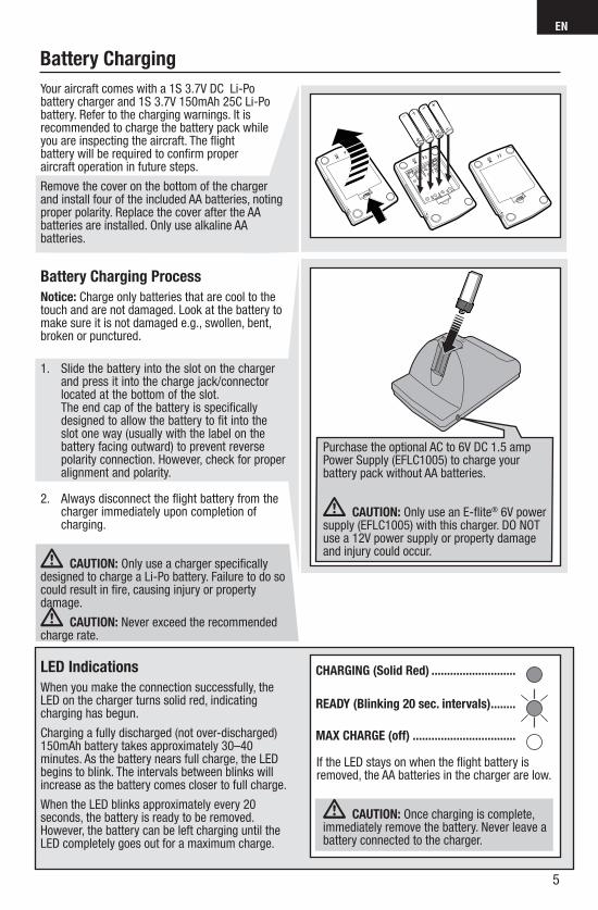
Your aircraft comes with a 1S 3.7V DC Li-Po battery charger and 1S 3.7V 150mAh 25C Li-Po battery. Refer to the charging warnings. It is recommended to charge the battery pack while you are inspecting the aircraft. The fl ight battery will be required to confi rm proper aircraft operation in future steps.
Remove the cover on the bottom of the charger and install four of the included AA batteries, noting proper polarity. Replace the cover after the AA batteries are installed. Only use alkaline AA batteries.
Battery Charging Process
Notice: Charge only batteries that are cool to the touch and are not damaged. Look at the battery to make sure it is not damaged e.g., swollen, bent, broken or punctured.
1. Slide the battery into the slot on the charger and press it into the charge jack/connector located at the bottom of the slot. The end cap of the battery is specifically designed to allow the battery to fit into the slot one way (usually with the label on the battery facing outward) to prevent reverse polarity connection. However, check for proper alignment and polarity.
2. Always disconnect the flight battery from the charger immediately upon completion of charging.
CAUTION: Only use a charger specifi cally designed to charge a Li-Po battery. Failure to do so could result in fi re, causing injury or property damage.
CAUTION: Never exceed the recommendedcharge rate.
LED Indications
When you make the connection successfully, the LED on the charger turns solid red, indicating charging has begun.
Charging a fully discharged (not over-discharged) 150mAh battery takes approximately 30–40 minutes. As the battery nears full charge, the LED begins to blink. The intervals between blinks will increase as the battery comes closer to full charge.
When the LED blinks approximately every 20 seconds, the battery is ready to be removed. However, the battery can be left charging until the LED completely goes out for a maximum charge.
CHARGING (Solid Red) ...........................
READY (Blinking 20 sec. intervals) ........
MAX CHARGE (off) .................................
Purchase the optional AC to 6V DC 1.5 amp Power Supply (EFLC1005) to charge your battery pack without AA batteries.
CAUTION: Only use an E-fl ite® 6V power supply (EFLC1005) with this charger. DO NOT use a 12V power supply or property damage and injury could occur.
If the LED stays on when the fl ight battery is removed, the AA batteries in the charger are low.
CAUTION: Once charging is complete, immediately remove the battery. Never leave a battery connected to the charger.
Battery Charging
6
EN
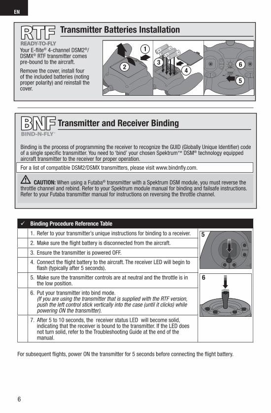
Binding is the process of programming the receiver to recognize the GUID (Globally Unique Identifi er) code of a single specifi c transmitter. You need to ‘bind’ your chosen Spektrum™ DSM® technology equipped aircraft transmitter to the receiver for proper operation.
For a list of compatible DSM2/DSMX transmitters, please visit www.bindnfl y.com.
CAUTION: When using a Futaba® transmitter with a Spektrum DSM module, you must reverse the throttle channel and rebind. Refer to your Spektrum module manual for binding and failsafe instructions. Refer to your Futaba transmitter manual for instructions on reversing the throttle channel.
Transmitter and Receiver Binding
Binding Procedure Reference Table
1. Refer to your transmitter’s unique instructions for binding to a receiver.
6
5
2. Make sure the fl ight battery is disconnected from the aircraft.
3. Ensure the transmitter is powered OFF.
4. Connect the fl ight battery to the aircraft. The receiver LED will begin to fl ash (typically after 5 seconds).
5. Make sure the transmitter controls are at neutral and the throttle is in the low position.
6. Put your transmitter into bind mode. (If you are using the transmitter that is supplied with the RTF version, push the left control stick vertically into the case (until it clicks) while powering ON the transmitter).
7. After 5 to 10 seconds, the receiver status LED will become solid, indicating that the receiver is bound to the transmitter. If the LED does not turn solid, refer to the Troubleshooting Guide at the end of the manual.
For subsequent fl ights, power ON the transmitter for 5 seconds before connecting the fl ight battery.
Transmitter Batteries Installation
3
4
1
2 6
5
Your E-fl ite® 4-channel DSM2®/DSMX® RTF transmitter comes pre-bound to the aircraft.
Remove the cover, install four of the included batteries (noting proper polarity) and reinstall the cover.
7
EN
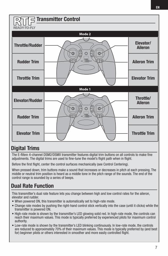
The E-fl ite® 4-channel DSM2/DSMX transmitter features digital trim buttons on all controls to make fi ne adjustments. The digital trims are used to fi ne-tune the model’s fl ight path when in fl ight.
Before the fi rst fl ight, center the control surfaces mechanically (see Control Centering).
When pressed down, trim buttons make a sound that increases or decreases in pitch at each pressing. The middle or neutral trim position is heard as a middle tone in the pitch range of the sounds. The end of the control range is sounded by a series of beeps.
This transmitter’s dual rate feature lets you change between high and low control rates for the aileron, elevator and rudder.• When powered ON, this transmitter is automatically set to high-rate mode.
• Change rate modes by pushing the right-hand control stick vertically into the case (until it clicks) while the transmitter is powered ON.
• High-rate mode is shown by the transmitter’s LED glowing solid red. In high-rate mode, the controls can reach their maximum values. This mode is typically preferred by experienced pilots for maximum control authority.
• Low-rate mode is shown by the transmitter’s LED blinking continuously. In low-rate mode, the controls are reduced to approximately 70% of their maximum values. This mode is typically preferred by (and best for) beginner pilots or others interested in smoother and more easily controlled fl ight.
Mode 2
Throttle/RudderElevator/Aileron
Rudder Trim Aileron Trim
Throttle Trim Elevator Trim
Mode 1
Elevator/RudderThrottle/Aileron
Rudder Trim Aileron Trim
Elevator Trim Throttle Trim
Transmitter Control
Digital Trims
Dual Rate Function
8
EN
Flight Battery Installation and ESC Arming
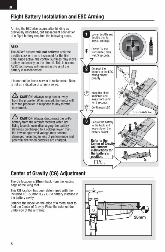
Arming the ESC also occurs after binding as previously described, but subsequent connection of a fl ight battery requires the following steps.
AS3X
The AS3X® system will not activate until the throttle stick or trim is increased for the fi rst time. Once active, the control surfaces may move rapidly and noisily on the aircraft. This is normal. AS3X technology will remain active until the battery is disconnected.
It is normal for linear servos to make noise. Noise is not an indication of a faulty servo.
CAUTION: Always keep hands awayfrom the propeller. When armed, the motor willturn the propeller in response to any throttle movement.
CAUTION: Always disconnect the Li-Po battery from the aircraft receiver when not fl ying to avoid over-discharging the battery. Batteries discharged to a voltage lower than the lowest approved voltage may become damaged, resulting in loss of performance and potential fi re when batteries are charged.
3
1-2-3-4-5 Sec.
2
1 Lower throttle and throttle trim to lowest settings.
Power ON the transmitter, then wait 5 seconds.
Connect the battery to the ESC, noting proper polarity.
Keep the plane immobile and away from wind for 5 seconds.
Continuous LED
Secure the battery to the hook and loop strip on the battery holder.
Refer to the Center of Gravity Adjustment instructions for the battery’s position.
FLY...
Center of Gravity (CG) Adjustment
The CG location is 28mm back from the leading edge at the wing root.
This CG location has been determined with the included 1S 150mAh 3.7V Li-Po battery installed in the battery cavity.
Balance the model on the edge of a metal ruler to fi nd the Center of Gravity. Place the ruler on the underside of the airframe.
28mm
9
EN
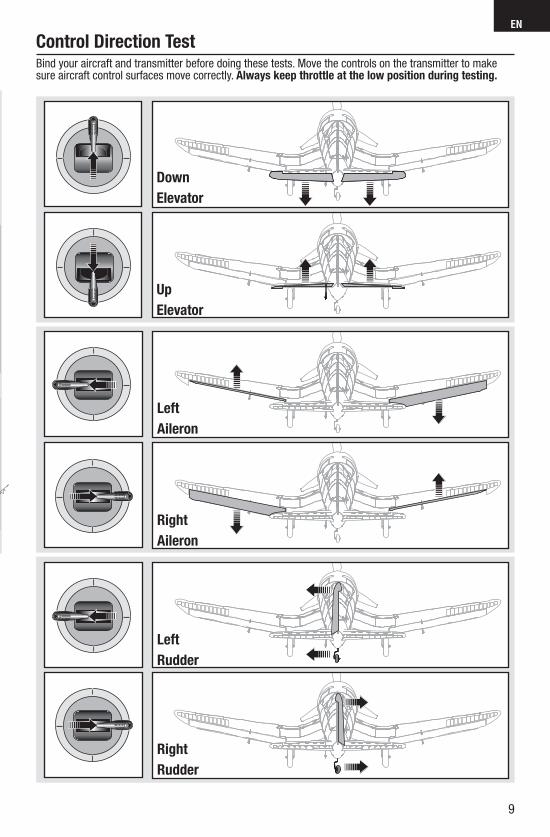
Bind your aircraft and transmitter before doing these tests. Move the controls on the transmitter to make sure aircraft control surfaces move correctly. Always keep throttle at the low position during testing.
Down
Elevator
Left
Aileron
Right
Aileron
Right
Rudder
Left
Rudder
Up
Elevator
Control Direction Test
10
EN
Before the fi rst fl ights, or in the event of an accident, make sure the fl ight control surfaces are centered. Adjust the linkages mechanically if the control surfaces are not centered. Use of the transmitter sub-trims may not correctly center the aircraft control surfaces due to the mechanical limits of linear servos. 1. Make sure the control surfaces are neutral when the transmitter controls and trims are centered. The transmitter sub-trim must always be set to zero.2. When needed, use a pair of pliers to carefully bend the metal linkage (see illustration).3. Make the U-shape narrower to make the connector shorter. Make the U-shape wider to make the linkage longer.
Centering Controls After First Flights
For best performance with AS3X, it is important that excessive trim is not used. If the aircraft requires excessive transmitter trim (4 or more clicks of trim per channel), return the transmitter trim to zero and adjust the linkages mechani-cally so that the control surfaces are in the fl ight trimmed position.
Control Centering
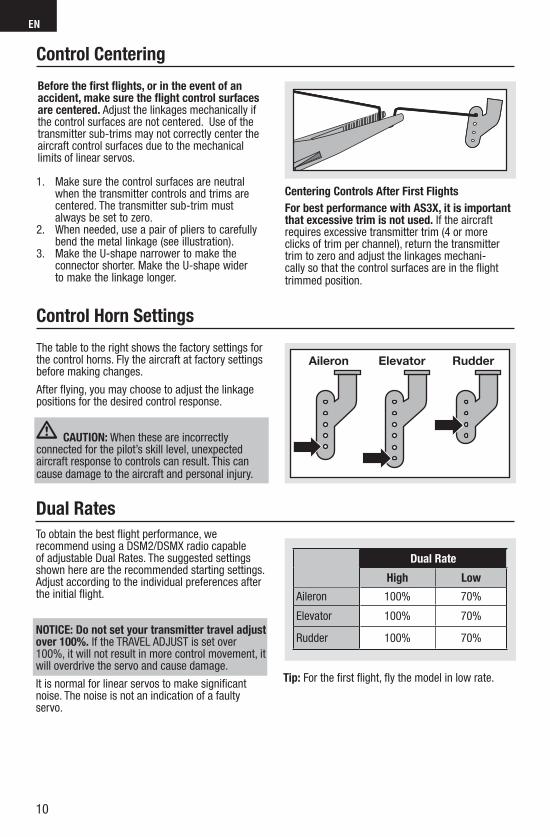
Control Horn Settings
The table to the right shows the factory settings for the control horns. Fly the aircraft at factory settings before making changes.
After fl ying, you may choose to adjust the linkage positions for the desired control response.
CAUTION: When these are incorrectly connected for the pilot’s skill level, unexpected aircraft response to controls can result. This can cause damage to the aircraft and personal injury.
Aileron Elevator Rudder
Dual Rates
To obtain the best fl ight performance, we recommend using a DSM2/DSMX radio capable of adjustable Dual Rates. The suggested settings shown here are the recommended starting settings. Adjust according to the individual preferences after the initial fl ight.
NOTICE: Do not set your transmitter travel adjust over 100%. If the TRAVEL ADJUST is set over 100%, it will not result in more control movement, it will overdrive the servo and cause damage.
It is normal for linear servos to make signifi cant noise. The noise is not an indication of a faulty servo.
Tip: For the fi rst fl ight, fl y the model in low rate.
Dual Rate
High Low
Aileron 100% 70%
Elevator 100% 70%
Rudder 100% 70%
11
EN
We recommend fl ying your aircraft outside in calm conditions. Always avoid fl ying near houses, trees, wires and buildings. You should also be careful to avoid fl ying in areas where there are many people, such as busy parks, schoolyards or soccer fi elds. Consult local laws and ordinances before choosing a location to fl y your aircraft.
Takeoff
Place the aircraft in position for takeoff (facing into the wind if fl ying outdoors). Set dual rates to low position and gradually increase the throttle to ¾ to full and steer with the rudder. Pull back gently on the elevator and climb to check trim. Once the trim is adjusted, begin exploring the fl ight envelope of the aircraft.
Landing
Land into the wind. This is very important for this model. Fly the aircraft to approximately 6 inches (15cm) or less above the runway, using a small amount of throttle for the entire descent. Keep the throttle on until the aircraft is ready to fl are. During fl are, keep the wings level and the airplane pointed into the wind. Gently lower the throttle while pulling back on the elevator to bring the aircraft down on all three wheels.
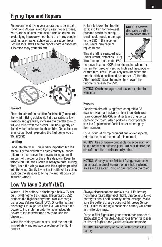
Failure to lower the throttle stick and trim to the lowest possible positions during a crash could result in damage to the ESC in the receiver unit, which may require replacement.
This aircraft is equipped with Over Current Protection (OCP). This feature protects the ESC from overheating. OCP stops the motor when the transmitter throttle is set too high and the propeller cannot turn. The OCP will only activate when the throttle stick is positioned just above 1/2 throttle. After the ESC stops the motor, fully lower the throttle to re-arm the ESC.
NOTICE: Crash damage is not covered under the warranty.
Repairs
Repair the aircraft using foam-compatible CA (cyanoacrylate adhesive) or clear tape. Only use foam-compatible CA, as other types of glue can damage the foam. When parts are not repairable, see the Replacement Parts List for ordering by item number.
For a listing of all replacement and optional parts, refer to the list at the end of this manual.
NOTICE: Use of foam-compatible CA accelerant on your aircraft can damage paint. DO NOT handle the aircraft until the accelerant fully dries.
NOTICE: When you are fi nished fl ying, never leave the aircraft in direct sunlight or in a hot, enclosed area such as a car. Doing so can damage the foam.
Flying Tips and Repairs
When a Li-Po battery is discharged below 3V per cell, it will not hold a charge. The aircraft’s ESC protects the fl ight battery from over-discharge using Low Voltage Cutoff (LVC). Once the battery discharges to 3V per cell, the LVC will reduce the power to the motor in order to leave adequate power to the receiver and servos to land the airplane.
When the motor power pulses, land the aircraft immediately and replace or recharge the fl ight battery.
Always disconnect and remove the Li-Po battery from the aircraft after each fl ight. Charge your Li-Po battery to about half capacity before storage. Make sure the battery charge does not fall below 3V per cell. Failure to unplug a connected battery will result in trickle discharge.
For your fi rst fl ights, set your transmitter timer or a stopwatch to 4 minutes. Adjust your timer for longer or shorter fl ights once you have fl own the model.
NOTICE: Repeated fl ying to LVC will damage the battery.
Low Voltage Cutoff (LVC)
NOTICE: Always decrease throttle at propeller strike.
12
EN
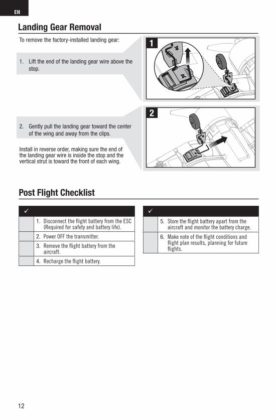
To remove the factory-installed landing gear:
1. Lift the end of the landing gear wire above the
stop.
2. Gently pull the landing gear toward the center
of the wing and away from the clips.
Install in reverse order, making sure the end of the landing gear wire is inside the stop and the vertical strut is toward the front of each wing.
1
2
Landing Gear Removal
Post Flight Checklist
1. Disconnect the fl ight battery from the ESC (Required for safety and battery life).
2. Power OFF the transmitter.
3. Remove the fl ight battery from the aircraft.
4. Recharge the fl ight battery.
5. Store the fl ight battery apart from the aircraft and monitor the battery charge.
6. Make note of the fl ight conditions and fl ight plan results, planning for future fl ights.
13
EN
Power Components Service
11
2 x
90
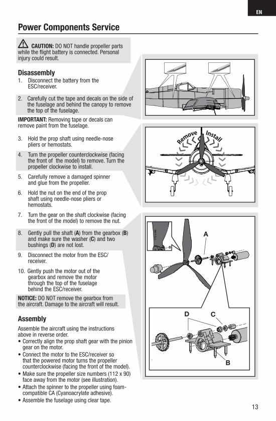
CAUTION: DO NOT handle propeller parts while the fl ight battery is connected. Personal injury could result.
Disassembly1. Disconnect the battery from the
ESC/receiver.
2. Carefully cut the tape and decals on the side of the fuselage and behind the canopy to remove the top of the fuselage.
IMPORTANT: Removing tape or decals can remove paint from the fuselage.
3. Hold the prop shaft using needle-nose pliers or hemostats.
4. Turn the propeller counterclockwise (facing the front of the model) to remove. Turn the propeller clockwise to install.
5. Carefully remove a damaged spinner and glue from the propeller.
6. Hold the nut on the end of the prop shaft using needle-nose pliers or hemostats.
7. Turn the gear on the shaft clockwise (facing the front of the model) to remove the nut.
8. Gently pull the shaft (A) from the gearbox (B) and make sure the washer (C) and two bushings (D) are not lost.
9. Disconnect the motor from the ESC/ receiver.
10. Gently push the motor out of the gearbox and remove the motor through the top of the fuselage behind the ESC/receiver.
NOTICE: DO NOT remove the gearbox from the aircraft. Damage to the aircraft will result.
Assembly
Assemble the aircraft using the instructions above in reverse order.• Correctly align the prop shaft gear with the pinion
gear on the motor.
• Connect the motor to the ESC/receiver so that the powered motor turns the propeller counterclockwise (facing the front of the model).
• Make sure the propeller size numbers (112 x 90) face away from the motor (see illustration).
• Attach the spinner to the propeller using foam-compatible CA (Cyanoacrylate adhesive).
• Assemble the fuselage using clear tape.
A
D
B
C
Install
Remove
11
2 x
90
14
EN
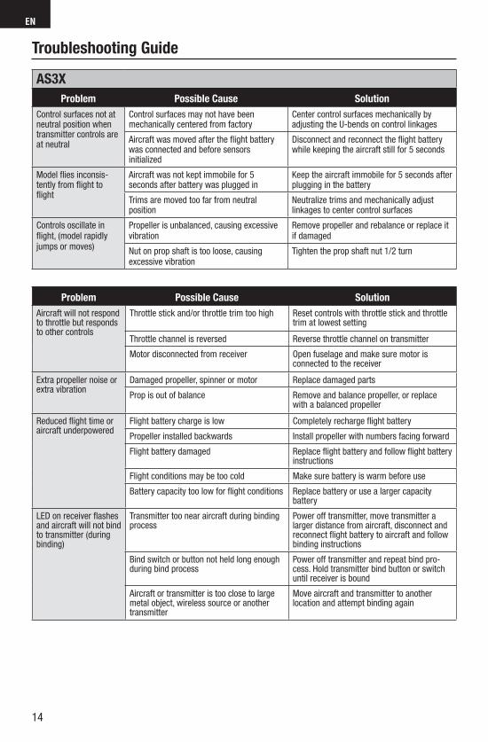
AS3X
Problem Possible Cause SolutionControl surfaces not at neutral position when transmitter controls are at neutral
Control surfaces may not have been mechanically centered from factory
Center control surfaces mechanically by adjusting the U-bends on control linkages
Aircraft was moved after the fl ight battery was connected and before sensors initialized
Disconnect and reconnect the fl ight battery while keeping the aircraft still for 5 seconds
Model fl ies inconsis-tently from fl ight to fl ight
Aircraft was not kept immobile for 5 seconds after battery was plugged in
Keep the aircraft immobile for 5 seconds after plugging in the battery
Trims are moved too far from neutral position
Neutralize trims and mechanically adjust linkages to center control surfaces
Controls oscillate in fl ight, (model rapidly jumps or moves)
Propeller is unbalanced, causing excessive vibration
Remove propeller and rebalance or replace it if damaged
Nut on prop shaft is too loose, causing excessive vibration
Tighten the prop shaft nut 1/2 turn
Problem Possible Cause SolutionAircraft will not respond to throttle but responds to other controls
Throttle stick and/or throttle trim too high Reset controls with throttle stick and throttle trim at lowest setting
Throttle channel is reversed Reverse throttle channel on transmitter
Motor disconnected from receiver Open fuselage and make sure motor is connected to the receiver
Extra propeller noise or extra vibration
Damaged propeller, spinner or motor Replace damaged parts
Prop is out of balance Remove and balance propeller, or replace with a balanced propeller
Reduced fl ight time or aircraft underpowered
Flight battery charge is low Completely recharge fl ight battery
Propeller installed backwards Install propeller with numbers facing forward
Flight battery damaged Replace fl ight battery and follow fl ight battery instructions
Flight conditions may be too cold Make sure battery is warm before use
Battery capacity too low for fl ight conditions Replace battery or use a larger capacity battery
LED on receiver fl ashes and aircraft will not bind to transmitter (during binding)
Transmitter too near aircraft during binding process
Power off transmitter, move transmitter a larger distance from aircraft, disconnect and reconnect fl ight battery to aircraft and follow binding instructions
Bind switch or button not held long enough during bind process
Power off transmitter and repeat bind pro-cess. Hold transmitter bind button or switch until receiver is bound
Aircraft or transmitter is too close to large metal object, wireless source or another transmitter
Move aircraft and transmitter to anotherlocation and attempt binding again
Troubleshooting Guide
15
EN
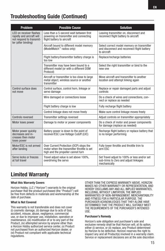
Problem Possible Cause SolutionLED on receiver fl ashes rapidly and aircraft will not respond to transmit-ter (after binding)
Less than a 5-second wait between fi rst powering on transmitter and connecting fl ight battery to aircraft
Leaving transmitter on, disconnect and reconnect fl ight battery to aircraft
Aircraft bound to different model memory (ModelMatch™ radios only)
Select correct model memory on transmitter and disconnect and reconnect fl ight battery to aircraft
Flight battery/transmitter battery charge is too low
Replace/recharge batteries
Transmitter may have been bound to a different model (or with a different DSM Protocol)
Select the right transmitter or bind to the new one
Aircraft or transmitter is too close to large metal object, wireless source or another transmitter
Move aircraft and transmitter to anotherlocation and attempt linking again
Control surface does not move
Control surface, control horn, linkage or servo damage
Replace or repair damaged parts and adjust controls
Wire damaged or connections loose Do a check of wires and connections, con-nect or replace as needed
Flight battery charge is low Fully recharge fl ight battery
Control linkage does not move freely Make sure control linkage moves freely
Controls reversed Transmitter settings reversed Adjust controls on transmitter appropriately
Motor loses power Damage to motor or power components Do a check of motor and power components for damage (replace as needed)
Motor power quickly decreases and in-creases then motor loses power
Battery power is down to the point of receiver/ESC Low Voltage Cutoff (LVC)
Recharge fl ight battery or replace battery that is no longer performing
Motor/ESC is not armed after landing
Over Current Protection (OCP) stops the motor when the transmitter throttle is set high and the propeller cannot turn
Fully lower throttle and throttle trim to arm ESC
Servo locks or freezes at full travel
Travel adjust value is set above 100%, overdriving the servo
Set Travel adjust to 100% or less and/or set sub-trims to Zero and adjust linkages mechanically
Troubleshooting Guide (Continued)
What this Warranty Covers
Horizon Hobby, LLC (“Horizon”) warrants to the original purchaser that the product purchased (the “Product”) will be free from defects in materials and workmanship at the date of purchase.
What is Not Covered
This warranty is not transferable and does not cover (i) cosmetic damage, (ii) damage due to acts of God, accident, misuse, abuse, negligence, commercial use, or due to improper use, installation, operation or maintenance, (iii) modifi cation of or to any part of the Product, (iv) attempted service by anyone other than a Horizon Hobby authorized service center, (v) Product not purchased from an authorized Horizon dealer, or (vi) Product not compliant with applicable technical regulations.
OTHER THAN THE EXPRESS WARRANTY ABOVE, HORIZON MAKES NO OTHER WARRANTY OR REPRESENTATION, AND HEREBY DISCLAIMS ANY AND ALL IMPLIED WARRANTIES, INCLUDING, WITHOUT LIMITATION, THE IMPLIED WARRANTIES OF NON-INFRINGEMENT, MERCHANTABILITY AND FITNESS FOR A PARTICULAR PURPOSE. THE PURCHASER ACKNOWLEDGES THAT THEY ALONE HAVE DETERMINED THAT THE PRODUCT WILL SUITABLY MEET THE REQUIREMENTS OF THE PURCHASER’S INTENDED USE.
Purchaser’s Remedy
Horizon’s sole obligation and purchaser’s sole and exclusive remedy shall be that Horizon will, at its option, either (i) service, or (ii) replace, any Product determined by Horizon to be defective. Horizon reserves the right to inspect any and all Product(s) involved in a warranty claim. Service or replacement decisions are at the sole discretion
Limited Warranty

16
EN
of Horizon. Proof of purchase is required for all warranty claims. SERVICE OR REPLACEMENT AS PROVIDED UNDER THIS WARRANTY IS THE PURCHASER’S SOLE AND EXCLUSIVE REMEDY.
Limitation of Liability
HORIZON SHALL NOT BE LIABLE FOR SPECIAL, INDIRECT, INCIDENTAL OR CONSEQUENTIAL DAMAGES, LOSS OF PROFITS OR PRODUCTION OR COMMERCIAL LOSS IN ANY WAY, REGARDLESS OF WHETHER SUCH CLAIM IS BASED IN CONTRACT, WARRANTY, TORT, NEGLIGENCE, STRICT LIABILITY OR ANY OTHER THEORY OF LIABILITY, EVEN IF HORIZON HAS BEEN ADVISED OF THE POSSIBILITY OF SUCH DAMAGES. Further, in no event shall the liability of Horizon exceed the individual price of the Product on which liability is asserted. As Horizon has no control over use, setup, fi nal assembly, modifi cation or misuse, no liability shall be assumed nor accepted for any resulting damage or injury. By the act of use, setup or assembly, the user accepts all resulting liability. If you as the purchaser or user are not prepared to accept the liability associated with the use of the Product, purchaser is advised to return the Product immediately in new and unused condition to the place of purchase.
Law
These terms are governed by Illinois law (without regard to confl ict of law principals). This warranty gives you specifi c legal rights, and you may also have other rights which vary from state to state. Horizon reserves the right to change or modify this warranty at any time without notice.
WARRANTY SERVICES
Questions, Assistance, and Services
Your local hobby store and/or place of purchase cannot provide warranty support or service. Once assembly, setup or use of the Product has been started, you must contact your local distributor or Horizon directly. This will enable Horizon to better answer your questions and service you in the event that you may need any assistance. For questions or assistance, please visit our website at www.horizonhobby.com, submit a Product Support Inquiry, or call the toll free telephone number referenced in the Warranty and Service Contact Information section to speak with a Product Support representative.
Inspection or Services
If this Product needs to be inspected or serviced and is compliant in the country you live and use the Product in, please use the Horizon Online Service Request submission process found on our website or call Horizon to obtain a Return Merchandise Authorization (RMA) number. Pack the Product securely using a shipping carton. Please note that original boxes may be included, but are not designed to withstand the rigors of shipping without additional protection. Ship via a carrier that provides
tracking and insurance for lost or damaged parcels, as Horizon is not responsible for merchandise until it arrives and is accepted at our facility. An Online Service Request is available at http://www.horizonhobby.com/content/_service-center_render-service-center. If you do not have internet access, please contact Horizon Product Support to obtain a RMA number along with instructions for submitting your product for service. When calling Horizon, you will be asked to provide your complete name, street address, email address and phone number where you can be reached during business hours. When sending product into Horizon, please include your RMA number, a list of the included items, and a brief summary of the problem. A copy of your original sales receipt must be included for warranty consideration. Be sure your name, address, and RMA number are clearly written on the outside of the shipping carton.
NOTICE: Do not ship LiPo batteries to Horizon. If you have any issue with a LiPo battery, please contact the appropriate Horizon Product Support offi ce.
Warranty Requirements
For Warranty consideration, you must include your original sales receipt verifying the proof-of-purchase date. Provided warranty conditions have been met, your Product will be serviced or replaced free of charge. Service or replacement decisions are at the sole discretion of Horizon.
Non-Warranty Service
Should your service not be covered by warranty, service will be completed and payment will be required without notifi cation or estimate of the expense unless the expense exceeds 50% of the retail purchase cost. By submitting the item for service you are agreeing to payment of the service without notifi cation. Service estimates are available upon request. You must include this request with your item submitted for service. Non-warranty service estimates will be billed a minimum of ½ hour of labor. In addition you will be billed for return freight. Horizon accepts money orders and cashier’s checks, as well as Visa, MasterCard, American Express, and Discover cards. By submitting any item to Horizon for service, you are agreeing to Horizon’s Terms and Conditions found on our website http://www.horizonhobby.com/content/_service-center_render-service-center.
ATTENTION: Horizon service is limited to Product compliant in the country of use and ownership. If received, a non-compliant Product will not be serviced. Further, the sender will be responsible for arranging return shipment of the un-serviced Product, through a carrier of the sender’s choice and at the sender’s expense. Horizon will hold non-compliant Product for a period of 60 days from notifi cation, after which it will be discarded.
FCC Information
This device complies with part 15 of the FCC rules. Operation is subject to the following two conditions: (1)This device may not cause harmful interference, and (2) this device must accept any interference received, including interference that may cause undesired operation.
CAUTION: Changes or modifi cations not expressly approved by the party responsible for compliance could void the user’s authority to operate the equipment.
This product contains a radio transmitter with wireless technology which has been tested and found to be compliant with the applicable regulations governing a radio transmitter in the 2.400GHz to 2.4835GHz frequency range.

17
EN
Declaration of Conformity
Compliance Information for the European Union
Robert PeakChief Financial Offi cer
Horizon Hobby, LLC
Warranty and Service Information
Instructions for disposal of WEEE by users in the European UnionThis product must not be disposed of with other waste. Instead, it is the user’s responsibility to dispose of their waste equipment by handing it over to a designated collections point for the recycling of waste electrical and electronic equipment. The separate collection and recycling of your waste equipment at the time of disposal will help to conserve natural resources and ensure that it is recycled in a manner that protects human health and the environment. For more
information about where you can drop off your waste equipment for recycling, please contact your local city offi ce, your household waste disposal service or where you purchased the product.
Country of Purchase Horizon Hobby Phone Number/Email Address Address
United States of America
Horizon Service Center(Repairs and Repair Requests)
servicecenter.horizonhobby.com/RequestForm/
4105 Fieldstone Rd Champaign, Illinois,
61822 USA
Horizon Product Support(Product Technical Assistance)
www.quickbase.com/db/bghj7ey8c?a=GenNewRecord
888-959-2305
888-959-2305
United KingdomService/Parts/Sales:
Horizon Hobby Limited
[email protected] Units 1–4 , Ployters Rd, Staple Tye Harlow, Essex,
CM18 7NS, United Kingdom+44 (0) 1279 641 097
GermanyHorizon Technischer Service [email protected] Christian-Junge-Straße 1
25337 Elmshorn, GermanySales: Horizon Hobby GmbH +49 (0) 4121 2655 100
France Service/Parts/Sales:Horizon Hobby SAS
[email protected] 11 Rue Georges Charpak77127 Lieusaint, France+33 (0) 1 60 18 34 90
China Service/Parts/Sales: Horizon Hobby – China
[email protected] Room 506, No. 97 Changshou Rd.
Shanghai, China 200060+86 (021) 5180 9868
(in accordance with ISO/IEC 17050-1)No. HH2014041701
Product(s): EFL Ultra Micro F4U Corsair with AS3X BNFItem Number(s): EFLU2680Equipment class: 1
The object of declaration described above is inconformity with the requirements of the specifi cations listed below, following the provisions of the European R&TTE directive 1999/5/EC, EMC Directive 2004/108/EC and LVD Directive 2006/95/EC
EN 301 489-1 V1.9.2: 2012EN 301 489-17 V2.1.1: 2009
EN60950-1:2006+A11:2009+A1:2010+A12: 2011
EN55022:2010 + AC:2011EN55024:2010
Signed for and on behalf of: Horizon Hobby, LLCChampaign, IL USAApril 17, 2014
(in accordance with ISO/IEC 17050-1)No. HH2014041702
Product(s): EFL Ultra Micro F4U Corsair with AS3X RTFItem Number(s): EFLU2600, EFLU2600M1Equipment class: 1
The object of declaration described above is in conformity with the requirements of the specifi cations listed below, following the provisions of the European R&TTE directive 1999/5/EC, EMC Directive 2004/108/EC and LVD Directive 2006/95/EC
EN 300-328 V1.7.1: 2006 EN 301 489-1 V1.9.2: 2012EN 301 489-17 V2.1.1: 2009
EN60950-1:2006+A11:2009+A1:2010+A12: 2011
EN55022:2010 + AC:2011EN55024:2010
Signed for and on behalf of: Horizon Hobby, LLCChampaign, IL USAApril 17, 2014
Robert PeakChief Financial Offi cer
Horizon Hobby, LLC
ICC InformationThis device complies with Industry Canada license-exempt RSS standard(s). Operation is subject to the following two conditions: (1) this device may not cause interference, and (2) this device must accept any interference, including interference that may cause undesired operation of the device.

67
Replacement Parts – Ersatzteile – – Pièces de rechange – Pezzi di ricambio –
Part # • Nummer Numéro • Codice Description Beschreibung Description Descrizione
PKZU1602Decal Sheet: UM F4U Corsair
Dekorbogen: UM F4U Corsair
Planche de décal-comanies : UM F4U Corsair
Foglio con decalco-manie: UM F4U Corsair
PKZU1603Landing Gear Set: UM F4U Corsair
Fahrgestellsatz: UM F4U Corsair
Jeu de train d’atterrissage : UM F4U Corsair
Set carrello di atter-raggio: UM F4U Corsair
PKZU1604Clear Canopy: UM F4U Corsair
Durchsichtige Kabinenhaube: UM F4U Corsair
Verrière transparente : UM F4U Corsair
Capottina trasparente: UM F4U Corsair
PKZU1608Spinner: UM F4U Corsair (4)
Spinner: UM F4U Corsair (4)
Cône d’hélice : UM F4U Corsair (4)
Ogiva: UM F4U Corsair (4)
PKZU1620Wing/Belly Pan Without Servo: UM F4U Corsair
Flügel / untere Verk-leidung ohne Servo: UM F4U Corsair
Aile/blindage inférieur sans servo : UM F4U Corsair
Carenatura ala/infe-riore, senza servo: UM F4U Corsair
PKZU1622Aileron Pushrod Linkage: UM F4U Corsair
Querrudergestänge: UM F4U Corsair
Liaison de commande d’aileron : UM F4U Corsair
Leveraggio asta di co-mando dell’alettone: UM F4U Corsair
PKZU1625Complete Tail Set: UM F4U Corsair
Vollständiger Heck-satz: UM F4U Corsair
Queue complète : UM F4U Corsair
Set completo coda: UM F4U Corsair
PKZU1626
Elevator/Rudder Pushrod Set: UM F4U Corsair
Höhen-/Seitenrud-ergestängesatz: UM F4U Corsair
Jeu de biellettes mécaniques de gouverne de profon-deur et de direction : UM F4U Corsair
Set asta di comando elevatore/timone: UM F4U Corsair
PKZU1667Bare Fuselage with Canopy: UM F4U Corsair
Blank Rumpf mit Kabinenhaube: UM F4U Corsair
Fuselage nu avec ver-rière : UM F4U Corsair
Fusoliera semplice con capottina: UM F4U Corsair
HBZ4929Gearbox (No Motor): Champ, UM T28, Corsair
Getriebe (ohne Mo-tor): Champ, UM T28, Corsair
Réducteur (sans moteur) : Champ, UM T28, Corsair
Riduttore (senza motore): Champ, UM T28, Corsair
PKZ3528Propeller Shaft: Sukhoi Su-26m, Micro P-51
Propellerwelle: Sukhoi Su-26m, Micro P-51
Arbre d’hélice : Sukhoi Su-26m, Micro P-51
Albero dell’elica: Sukhoi Su-26m, Micro P-51
PKZ3616Motor: Ultra Micro P-51, UM T-28
Motor: Ultra Micro P-51, UM T-28
Moteur : Ultra Micro P-51, UM T-28
Motore Ultra Micro P-51, UM T-28
EFLC1003DC 3.7V Li-Po Charger
DC-3,7V-Li-Po-Ladegerät
Chargeur Li-Po DC 3,7 V
Caricabatterie Li-Po CC da 3,7 V
EFL33412.4GHz Transmitter DSM2: Vapor
2,4GHz-DSM2-Sender: Vapor
Émetteur DSM2 2,4 GHz : Vapor
Trasmettitore DSM2 da 2,4 GHz: Vapor
EFLUP112903B112 x 90mm 3 Blade Propeller
112 x 90 mm-3-Blattpropeller
Hélice 3 pales 112 x 90 mm
Elica 112 x 90 mm a 3 lame
SPMSA2030LO
2.3-Gram Perfor-mance Linear Long Throw offset Servo
Spektrum 2,3 Gramm Linear Offset Servo
Servo linéaire offset course longue 2,3 g
Servo di offset corsa lunga lineari a prestazioni elevate da 2,3 grammi
EFLU2664
DSM2/DSMX UM AS3X Receiver/ESC, UM F4U Corsair
DSM2/DSMX AS3X Empfänger ESC, UM F4U Corsair
Récepteur DSM2/DSMX a avec contrôleur, UM F4U Corsair
DSM2/DSMX AS3X Ricevitore ESC, UM F4U Corsair

68
– Optional Parts and Accessories – – Optionale Bauteile und Zubehörteile – – Pièces optionnelles et accessoires –
– Pezzi opzionali e accessori –
Part # • Nummer Numéro • Codice Description Beschreibung Description Descrizione
PKZ1039Hook and Loop Set (5): Ultra Micros
Parkzone: Klettband Set Ultra Micros
Ultras Micros - Bande auto-agrippante (5)
Set fascette a strappo (5): Ultra Micro
EFLB1501S451S 3.7V 150mAh 45C Li-Po Battery
1S 3.7V 150mAh 45C Li-Po Akku
Batterie Li-Po 3.7V 1S 45C 150mA
1S 3.7V 150mAh 45C Li-Po Batteria
EFLB1501S251S 3.7V 150mAh 25C Li-Po Battery
1S 3.7V 150mAh 25C Li-Po Akku
Batterie Li-Po 3.7V 1S 25C 150mA
1S 3.7V 150mAh 25C Li-Po Batteria
EFLC1004
Celectra 4-Port 1S 3.7V 0.3A DC Li-Po Charger
Celectra-1S-3,7V-0,3A-DC-Li-Po-Ladegerät mit 4 Anschlüssen
Chargeur Li-Po CC 0,3 A 3, 7 V 1S 4 ports Celectra
Caricabatterie Li-Po 1S da 3,7 V 0,3 A CC, a 4 porte, Celectra
EFLC1005/UK/AU/EU
AC to 12V DC,1.5 AmpPower Supply (Basedupon your sales Region)
Netzteil 12V 1,5 A (Basierend nach Vertriebsregion)
Alimentation CA vers 12V CC, 1,5 A (En fonction de votre région)
Alimentatore CA - 12V CC da 1,5 A (in base al Paese di vendita)
DX4e DSMX 4-Channel Transmitter
DX4e DSMX 4-KanalSender
Emetteur DX4e DSMX4 voies
DX4e DSMX Trasmettitore 4 canali
DX5e DSMX 5-Channel Transmitter
DX5e DSMX 5-KanalSender
Emetteur DX5e DSMX5 voies
DX5e DSMX Trasmettitore 5 canali
DX6i DSMX 6-Channel Transmitter
DX6i DSMX 6-KanalSender
Emetteur DX6i DSMX6 voies
DX6i DSMX Trasmettitore 6 canali
DX6 DSMX 6-Channel Transmitter
DX6 DSMX 6-KanalSender
Emetteur DX6 DSMX6 voies
DX6 DSMX Trasmettitore 6 canali
DX7s DSMX7-Channel Transmitter
Spektrum DX7s7 Kanal Sender
Emetteur DX7s DSMX7 voies
DX7s DSMXTrasmettitore 7 canali
DX8 DSMX Transmitter
Spektrum DX8 nurSender
Emetteur DX8 DSMX8 voies
DX8 DSMX Solotrasmettitore
DX9 DSMX Transmitter
Spektrum DX9 nurSender
Emetteur DX9 DSMX9 voies
DX9 DSMX Solotrasmettitore
DX18 Transmitter Spektrum DX18 nurSender
Emetteur DX18 DSMX9 voies
DX18 DSMX Solotrasmettitore
69
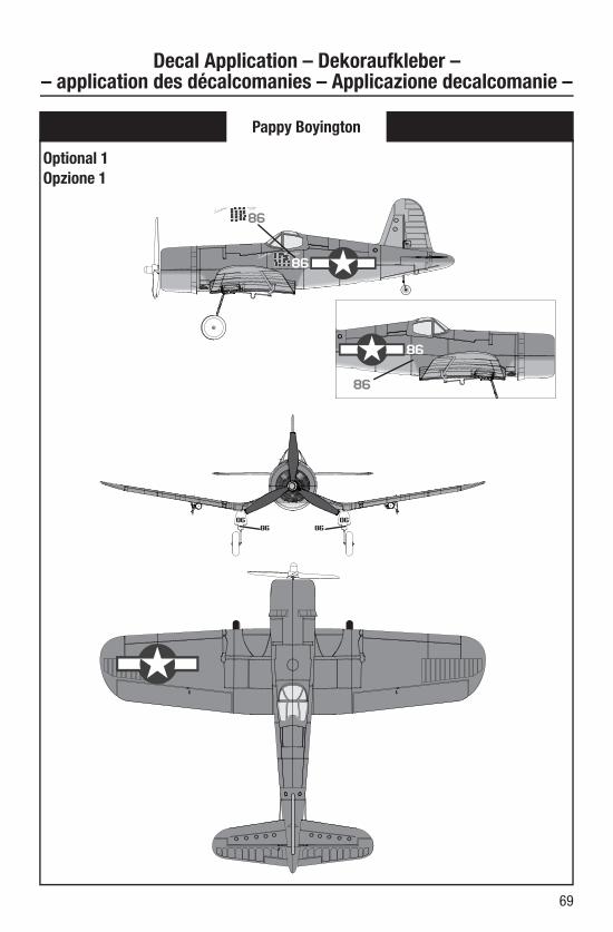
Pappy Boyington
Decal Application – Dekoraufkleber – – application des décalcomanies – Applicazione decalcomanie –
Optional 1
Opzione 1
70
LT.JG. KEPFORD
LT.JG. KEPFORD
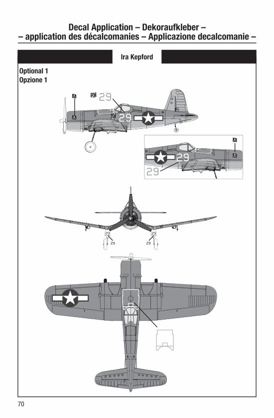
Ira Kepford
Optional 1
Opzione 1
Decal Application – Dekoraufkleber – – application des décalcomanies – Applicazione decalcomanie –

© 2014 Horizon Hobby, LLC.
E-fl ite, AS3X, Blade, Celectra, UMX, DSM, DSM2, DSMX, ModelMatch, Bind-N-Fly, the Bind-N-Fly logo and the Horizon Hobby logo are trademarks or registered trademarks of Horizon Hobby, LLC.
The Spektrum trademark is used with permission of Bachmann Industries, Inc.
Futaba is a registered trademark of Futaba Denshi Kogyo Kabushiki Kaisha Corporation of Japan.
Patents pending.
www.e-fl iterc.com
Created 4/14 38543EFLU2600, EFLU2680