Embed Size (px)
Citation preview

Date | Title of presentation | 2
Overview: Market Trend

Date | Title of presentation | 3
이동이동이동이동통신통신통신통신기술기술기술기술동향동향동향동향
“LTE”
“UMB”
“WiLAN(802.11n)”“WiMAX(802.16x)”
OFDMA
+MIMO
GSM/(E)GPRSWCDMA/HSPA
CDMA20001xEVDO
802.11x

Date | Title of presentation | 4
Overview
GSM
(EDGE)
GSM
(EDGE)WCDMA/
HSPA
WCDMA/
HSPA
EDGE II
HSPA+
EDGE II
HSPA+
LTE or
WiMAX
LTE or
WiMAX
GSM(EDGE)
GSM(EDGE)
WCDMA/HSPA
WCDMA/HSPA
GSM
(EDGE)
GSM
(EDGE)
CDMA2000CDMA2000
NothingNothing
1xEVDO1xEVDO
MIMO 적용적용적용적용 OFDMA 적용적용적용적용
== 요요요요 약약약약 ==
-현재현재현재현재시장시장시장시장 : 63억억억억인구의인구의인구의인구의약약약약 50% 이동통신이동통신이동통신이동통신이용이용이용이용
-현재현재현재현재 3GPP 시장시장시장시장점유율점유율점유율점유율 : 약약약약 80%
- 3GPP에서에서에서에서 LTE 전환전환전환전환시시시시 , 투자투자투자투자비용비용비용비용최소최소최소최소
- LTE 전환전환전환전환시시시시 , 시장시장시장시장점유율점유율점유율점유율유지유지유지유지및및및및향상향상향상향상가능가능가능가능
- LTE 기술이기술이기술이기술이 WiMAX기술기술기술기술대비대비대비대비우위우위우위우위
���� 단단단단 , 2년년년년정도의정도의정도의정도의 lunching gap
- WiMAX의의의의이동통신이동통신이동통신이동통신시장시장시장시장진입의진입의진입의진입의어려움어려움어려움어려움
���� LTE 대비대비대비대비기술력기술력기술력기술력저하저하저하저하
���� 투자투자투자투자비용의비용의비용의비용의과다과다과다과다
- WiMAX기대기대기대기대시장시장시장시장
���� 기존기존기존기존인터넷인터넷인터넷인터넷사업을사업을사업을사업을무선화무선화무선화무선화시시시시시장시장시장시장형성형성형성형성
���� USB, Note-PC 등에등에등에등에탑재된탑재된탑재된탑재된제품제품제품제품시장시장시장시장현재현재현재현재 이동통신이동통신이동통신이동통신현황현황현황현황
802.11x(WiLAN)
802.11x(WiLAN) 802.11n802.11n 802.11n802.11n

Date | Title of presentation | 5
UMTS Long Term Evolution (LTE) Ambitious targets
�Significantly increased peak data rate e.g. 100 Mbps (downlink) and 50 Mbps (uplink)
�Significantly improved spectrum efficiency ( e.g. 2-4 x Release 6)
� Improved latency:
� Possibility for a radio access network latency (user plane UE – RNC - UE) below
10 ms
� Significantly reduced control plane latency
�Scaleable bandwidth
� 5, 10, 15, 20 MHz
� Smaller bandwidths to allow flexibility in narrow spectral allocations
�Support for inter-working with existing 3G systems and non-3GPP specified systems
�Reduced CAPEX and OPEX including backhaul
�Cost effective migration from release 6 UTRA radio interface and architecture
�Efficient support of the various types of services, especially from the PS domain
�System should be optimized for low mobile speed but also support high mobile speed
�Operation in paired and unpaired spectrum should not be precluded (FDD and TDD modes)
�Enhanced Multimedia Broadcast Multicast Services (E-MBMS)

Date | Title of presentation | 6
UMTS Long Term Evolution(LTE) Deployment scenarios
�Standalone deployment scenario for EUTRAN
�Integrating with existing 2G/3G deployment scenario
� Handover to and from GERAN and UTRAN will be supported
� Study on handover to and from WiMAX and cdma2000 based
networks has been finalized
�LTE as overlay network on another frequency to increase overallcapacity in certain areas
�Narrower LTE carriers can also be introduced in legacy frequency bandssuch as 900 MHz
�LTE interworking with 3GPP2/WiMAX

Date | Title of presentation | 7
Network Structure

Date | Title of presentation | 8
Network Architecture
IMT-DS(Direct Spread)
UTRA FDD(WCDMA)
3GPP
IMT-TC(Time Code)
UTRA TDD(TD-S/CDMA)
3GPP
IMT-MC(Multi Carrier)
cdma2000
3GPP2
IMT-SC(Single Carrier)
UWC-136(EDGE)
UWCC/3GPP
IMT-FT(Freq. + Time)
DECT
ETSI
IMT-2000 RAT (ITU-R)
IMT-2000 CN
(ITU-T)
UMTS
CN ⇔ RAT Mapping
Gateways and Interworking Functions
GSM
(MAP)
ANSI-41
(IS-634)
IP-Net
v4, v6

Date | Title of presentation | 9
Circuit Switched
Packet Switched
Network Architecture – 3GPP

Date | Title of presentation | 10
Network Architecture – 3GPP
� VLR (Visitor Location Register)- User의 Ciphering and authentication 정보- 실제 Location Area의정보
� HLR (Home Location Register) - IMSI 기초로단말의위치를지속적으로관리하는데이터베이스- 착신호를받아단말의등록된 VLR 영역의 MSC로해당호전달- 실제 VLR의 Location 정보(단말의실제위치정보)
� EIR (Equipment Identity Register)- IMEI 등록및관리
� MSC (Mobile Switching Center) - location DB와연동
� SGSN (Serving GPRS Support Node)- 서비스지역내에서이동국과의 Packet 전달을담당하는 Node- 단말에대한이동성및보안 기능담당- HLR과연동하여 Mobility 관리(Packet의이동)- SGSN과 GGSN의 Session 관리(WAP,SMS, MMS등)
� GGSN- Packet Data 망(Mobile Network)과외부 Packet Data 망(IP Network)로의 Gateway- SGSN으로부터오는 Packet을적당한 PDP(Packet Data Protocol) 형식으로변환하여전송

Date | Title of presentation | 11
Network Architecture – 3GPP+LTE

Date | Title of presentation | 12
eNB functions:
l RRM, Radio Bearer Control, Radio Admission Control,
Connection Mobility Control, Scheduling for uplink and downlink
l IP header compression and encryption of user data stream
l Selection of an MME at UE attachment
l Routing of user plane data towards SAE Gateway
l Scheduling and transmissino of paging messages originated from MME
l Scheduling and transmission of broadcast informationoriginated
from MME or O&M
l Measurement and measurement reporting configuration
LTE Protocol ArchitectureNew network elements and functional split
SAE Gateway:
� Termination of user plane packets for paging reasons
� Switching of user plane for support of UE mobility
MME functions:
� Distribution of paging messages to eNBs
� Security Control
� Idle s tate mobility control
� SAE bearer ccontrol
� Ciphering and integrity protection of NAS Signalling

Date | Title of presentation | 13
OFDMA

Date | Title of presentation | 14
Wideband Signal
Non-Linear System
Fading
SINR
Amp. Design
Scalable BW

Date | Title of presentation | 15
Coherence Bandwidth
)(tx
Time domain view
στ delay spread
)( fX
Freq. domain view
High correlation of amplitudebetween two different freq.
components
Range of freq over
which response is flat
Bc
Coherence BW
- Max Frequency for “Flat” with 1 signal
- Max Frequency for “Comparison” with 2 signal

Date | Title of presentation | 16
Block Diagram Transmitter Receiver

Date | Title of presentation | 17
How to Increase Data Rates: Modulation
��������������������������������
��������������������������������
��������������������������������
��������������������������������
��������������������������������
��������������������������������
��������������������������������
��������������������������������
����������������
����������������
����������������
����������������
��������
��������
����
����
b1
b2
b3
b4
b5
b6
b7
b8
BPSK
1 symbol = 1 bitQPSK
1 symbol = 2 bit
16 QAM
1 symbol = 4 bit
64 QAM
1 symbol = 6 bitoptional for WiMAX
(+1)
(-1)
(+1,+1)
(+1,-1)(-1,-1)
(-1,+1)
bit to symbol mapping
b1 b1 b1 b1b2 b2 b2b3 b3 b4 b5 b6b4

Date | Title of presentation | 18
How to reach higher data rates?
Time
Time
1. Possibility: Reduce Symbol Time
S 1
S 2
S 1
S 2
S 1 S 1
S 2 S 2
delay spread
time time

Date | Title of presentation | 19
Weak Points & Solution
Time
Symbol 2
copy
cyclicprefix
useful symbol time
OFDMA symbol time
ICI (Inter-Carrier Interference)
ISI (Inter-Symbol Interference)
Date | Title of presentation | 20
ISI and ICI: Guard Intervall
lSymbol l-1
L
l+1
L
n
( )h n∗
L
L
L
L
L
L
Delay spread
Receiver DFT
Window
GT Delay Spread>
Guard Intervall guarantees the supression of ISI!
But, there is some week point in the “Amplifier”

Date | Title of presentation | 21
Receiver DFT
Window
Guard Intervall as Cyclic Prefix
lSymbol l-1
L
l+1
L
n
( )h n∗
L
L
L
L
L
L
Delay spread
GT Delay Spread>
Cyclic Prefix guarantees the supression of ISI and ICI!
Cyclic Prefix

Date | Title of presentation | 22
Degradation due to Frequency Offset
f
f∆
f0 f2Samples
f1 f3f0 f2f1 f3
2j nfe π∆
( )ls n ( )lr n
Channel

Date | Title of presentation | 23
Degradation due to Clock Offset
f
f0 f2Samples
f1 f3f0 f2f1 f3
ε( )ls n ( )lr n
Channel
f k∆ ∝

Date | Title of presentation | 24
•••••••••
•••••••••
•••••••••
•••••••••
•••••••••
•••••••••
•••••••••
Difference between OFDM and OFDMA
l OFDM allocates users in time
domain only
l OFDMA allocates users in time and
frequency domain
•••••••••
•••••••••
•••••••••
•••••••••
•••••••••
•••••••••
•••••••••
Time domain Time domain
Frequencydomain
Frequencydomain
User
3
User
3User
2
User
2
User
1
User
1

Date | Title of presentation | 25
Localized versus Distributed FDMA

Date | Title of presentation | 26
OFDMA vs SC-FDMA

Date | Title of presentation | 27
MIMO
Date | Title of presentation | 28
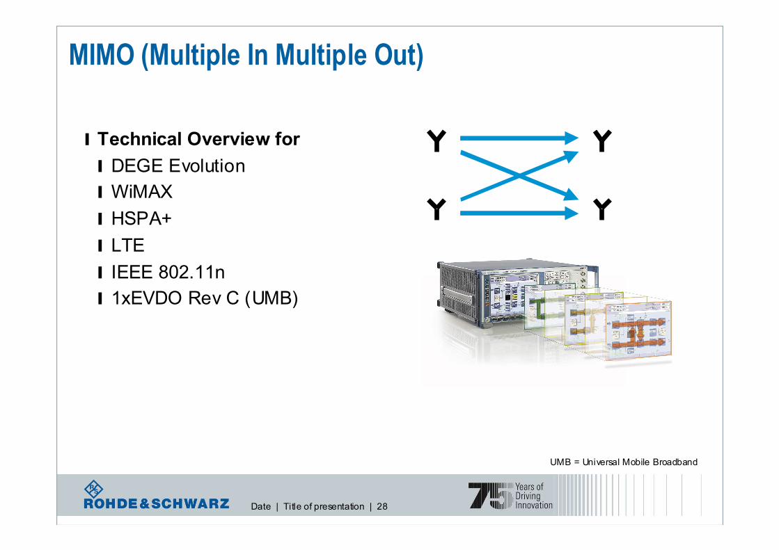
MIMO (Multiple In Multiple Out)
l Technical Overview for
l DEGE Evolution
l WiMAX
l HSPA+
l LTE
l IEEE 802.11n
l 1xEVDO Rev C (UMB)
UMB = Universal Mobile Broadband

Date | Title of presentation | 29
SU-MIMO versus MU-MIMO
s1 s2 sn
… …
UE1
UE2
UEn
� SU (Single User)-MIMO
l Goal: to increase user data rate
l Simultaneous transmission of
different data streams to 1 user
l Efficient when the user
experiences good channel conditions
� MU (Multiple User)-MIMO
l Goal: to increase sector capacity
l Selection of the users
experiencing good channel
conditions
l Efficient when a large number of users have an active data
transmission simultaneously

Date | Title of presentation | 30
MIMO & SIMO & MISO
Trans-
mitterReceiver
MIMO 2x2
Trans-
mitter Receiver
SIMO 1x2
Trans-mitter
Receiver
MISO 2x1

Date | Title of presentation | 31
MIMO modes
� Transmit diversity (TxD)� 사용사용사용사용목적목적목적목적 : Reliability 향상(Get a higher SNR at the Rx)
� Replicas of the same signal sent on several Tx antennas
� Array gain : Power
� Diversity gain : STBC/SFBC
� No Feedback
� Spatial multiplexing (SM)� 사용사용사용사용목적목적목적목적 : Data Throughput 향상
� Different data streams sent simultaneously on different antennas
� Higher data rate
� No diversity gain
� Limitation due to path correlation
� Beamforming� 사용사용사용사용목적목적목적목적 : Reliability/Data Throughput 향상
� Intelligent Antenna : Switched/Adaptive Antenna
� Some Feedback
� CDD (Cyclic Delay Diversity)� 사용사용사용사용목적목적목적목적 : Reliability 향상(Frequency Selectivity 및 Channel Decoder의 Performance 향상)

Date | Title of presentation | 32
� Transmit diversity:� Space Time Block Coding (STBC), Space Frequency Block Coding (SFBC)
� 2TX : STBC / 4TX : STBC+SFBC
� Increasing robustness of transmission
� Spatial Multiplexing에적용가능(2X1 or 3X2 or 4X2 MIMO인경우)
� Beamforming 적용(Adaptive Antenna)
� Indoor=TXD, Outdoor=BF 적합
� Open-SM & RI=1 일때, TXD 적용
� Spatial multiplexing:� Codebook based precoding
� Transmission of different data streams simultaneously over multiple spatial layers
� Beamforming 적용(Adaptive Antenna)
� CDD 적용(Zero, small delay and large delay)
� Closed-SM : 저속 UE, PMI/RI를 Feedback받아 Layer/Codeword/Precodeing결정(Zero, small Delay)
� Open-SM : 고속 UE, RI만이용하여 Layer/Codeword/Precoding 처리(Large Delay &RI>1)
LTE MIMO Downlink modes

Date | Title of presentation | 33
RX Diversity = SIMO
Aim:
increase of S/N ratio
���� increase of throughput
Trans-mitter
Recei-
ver
same signal via different paths
=> different fading
SNR
(dB)
Received Signals
Switched Diversity
C = max(A,B)
CA
B
Maximum Ratio Combining
C = (A+B)

Date | Title of presentation | 34
Receive Diversity

Date | Title of presentation | 35
TX Diversity = MISO
TXData
Proces-
sing
TX
Data
“Intelligence on RX side“
RX
Data Proces-
sing
RXData
“Intelligence on TX side“
Motivation for Alamouti Space-Time-Coding:- increase of range,
- improvement of BER,
- improvement of antenna diversity,
- improvement of signal quality

Date | Title of presentation | 36
-s2*
s1 s2
Space Time Coding
time
space
Section of the
input bit-stream
Alamouti Matrix
Matrix A
-s2*
s1 s2
s1*
s1 s2-s2* s1*
s1*
s1 s2-s2* s1*
s1 s2
math.
operation s1 s2
s1 s2=
Receiver
Transmitter

Date | Title of presentation | 37
Transmit diversity

Date | Title of presentation | 38
Spatial Multiplexing (MIMO 2x2)
TX RXs1 s2 s3 s4
s1
s2
s3
s4
s1 s2 s3 s4
Motivation for Space-Time-Coding with Matrix B:
- increase of data rate by multiplexing (theory by factor 2)

Date | Title of presentation | 39
MIMO with the SMU: K74 SW option

Date | Title of presentation | 40
The MIMO promise
� Channel capacity grows linearly with antennas ☺☺☺☺
� Assumptions ����� Perfect channel knowledge � Spatially uncorrelated fading
� Reality ����� Imperfect channel knowledge� Correlation ≠ 0 and rather unknown
Max Capacity ~ min(NTX, NRX)

Date | Title of presentation | 41
MIMO channel
know
Singular Value
Decomposition
r = H s + n
s1
s2
r1
r2
channel H
MIMO
wanted
r = D s + n~ ~~
s1
s2
r1
r2
channel D
~
~ ~
~SISO

Date | Title of presentation | 42
MIMO channel
s1
s2
r1
r2
channel H
MIMO
s1
s2
r1
r2
channel D
~
~ ~
~SISO
H =h11
h21
h12
h22
D =d1
0
0
d2
h11
h22
h12
h21
d1
d2
This is the reality ����
What we like to have ☺☺☺☺
Mathematical
Wizard: SVD
Date | Title of presentation | 43
h11
h21
h12
h22
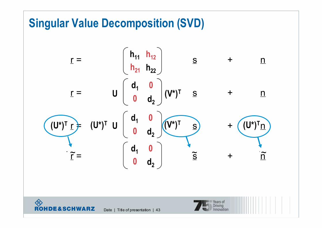
r = H s + n
r = H s + n
Singular Value Decomposition (SVD)
(U*)T (U*)T(U*)T
h11
h21
h12
h22
U (V*)Td1
0
0
d2
r = D s + nU (V*)Td1
0
0
d2
(U*)T (U*)T(U*)T U (V*)Tr = D s + nd1
0
0
d2
~~ ~

Date | Title of presentation | 44
Downlink spatial multiplexing - precoding
l The signal is “pre-coded” at Node B side before transmission
l Optimum precoding matrix is selected from predefined “codebook” known at Node B and UE side
l UE estimates the channel, selects the best precoding matrix at the
moment and sends back its index

Date | Title of presentation | 45
MIMO: avoid inter-channel interference
Idea: F adapts transmitted signal to current channel conditions
Link adaptation
Transmitter
F
H+
+
Space time
receiver
xk yk
V1,k
VM,k
Feedback about H
e.g. linear precoding:
Y=H*F*S+V
S
Date | Title of presentation | 46
d(0)d(1)
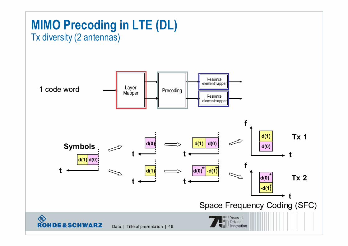
MIMO Precoding in LTE (DL)Tx diversity (2 antennas)
Tx 1
d(0)d(1)
t
Symbolsd(0)
t
Tx 2d(1)
t
t
t
d(0) * -d(1)*
LayerMapper Precoding
Resourceelementmapper
d(0)
d(1)
d(0) *
-d(1)*
t
f
t
f
Resourceelementmapper
1 code word
Space Frequency Coding (SFC)

Date | Title of presentation | 47
MIMO Precoding in LTE (DL)Tx diversity (4 antennas)
d(0)d(1)d(2)d(3)
t
Symbols
d(0)
t
d(1)
t
d(2)
t
d(3)
t
d(0)d(1)00
t
00d(2)d(3)
t
00
t
00
t
-d(1)*d(0)*
d(2)* -d(3)*
Tx 1
d(0)
d(1)
t
f
0
0
Tx 2
t
f
0
0
Tx 3
t
f
0
0
Tx 4
t
f
0
0
d(2)
d(3)
-d(1)*
d(0)*
d(2)*
-d(3)*
1 code word
Not all antennas transmit at the same time and frequency !

Date | Title of presentation | 48
MIMO Precoding in LTE (DL)Spatial multiplexing – Code book for precoding
Codebook
index
Number of layers υ
1 2
0
0
1
10
01
2
1
1
1
0
−11
11
2
1
2
1
1
2
1
− jj
11
2
1
3
−1
1
2
1 -
4
j
1
2
1 -
5
− j
1
2
1 -
Code book for 2 Tx:
Additional multiplication of the layer
symbols with codebook entry

Date | Title of presentation | 49
MIMO Precoding in LTE (DL)Spatial multiplexing – Code book for precoding
2 examples for 2 layers and 2 Tx antennas
10
01
2
1
−11
11
2
1
d(0)d(1)
t
Layer 1
b(0)b(1)
t
Layer 2
d(0)d(1)
t
Layer 1
b(0)b(1)
t
Layer 2
Tx 1
Tx 2
d(0)
d(1)
b(1)
b(0)
t
f
t
f
2
1
2
1
Tx 1
Tx 2
t
f
t
f

Date | Title of presentation | 50
But there is more to LTE layer 1 than just MIMO…
� LTE physical layer procedures
� Cell search
� Link Adaptation
� Power control
� Uplink synchronisation and Uplink timing control
� Random access related procedures
� Support of HARQ related procedures

Date | Title of presentation | 51
Some technical details of LTE / EUTRA

Date | Title of presentation | 52
UMTS Long Term Evolution (LTE) All new again, here‘s what is most important:
l New radio transmission schemes
l OFDMA in downlink:
Orthogonal Frequency Division Multiple
Access
l SC-FDMA in uplink:
Single Carrier Frequency Division Multiple
Access
l MIMO Multiple antenna technology
l New radio protocol architecture
l Complexity reduction
l Focus on shared channel operation, no
dedicated channels any more
l New network architecture
l New functional split between radio network nodes
l More functionality in the base station (eNodeB)
l Focus on packet switched domain
l System architecture evolution (SAE)
l MBMS
l Support of Multimedia Broadcast, Multicast Service

Date | Title of presentation | 53
LTE Physical Layer
Date | Title of presentation | 54
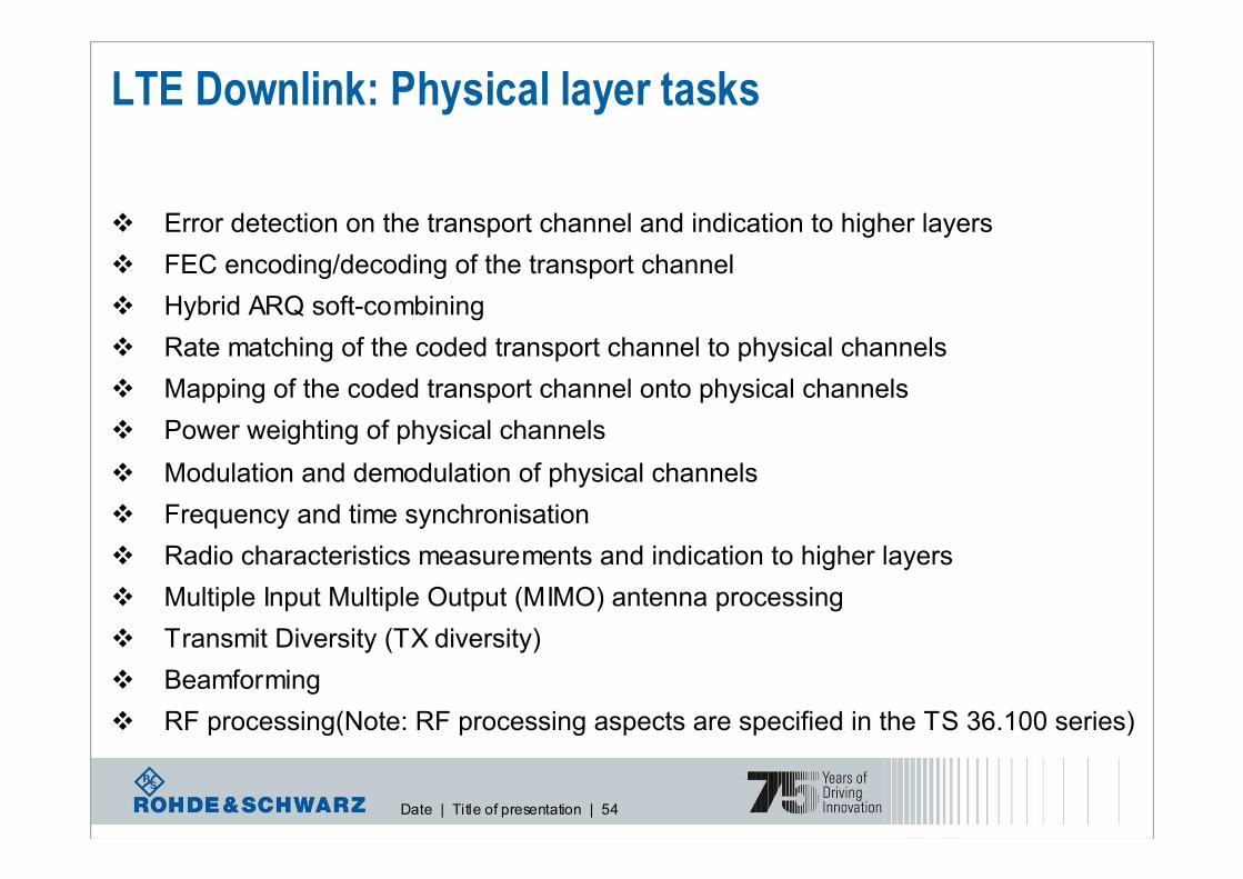
LTE Downlink: Physical layer tasks
� Error detection on the transport channel and indication to higher layers
� FEC encoding/decoding of the transport channel
� Hybrid ARQ soft-combining
� Rate matching of the coded transport channel to physical channels
� Mapping of the coded transport channel onto physical channels
� Power weighting of physical channels
� Modulation and demodulation of physical channels
� Frequency and time synchronisation
� Radio characteristics measurements and indication to higher layers
� Multiple Input Multiple Output (MIMO) antenna processing
� Transmit Diversity (TX diversity)
� Beamforming
� RF processing(Note: RF processing aspects are specified in the TS 36.100 series)
Date | Title of presentation | 55
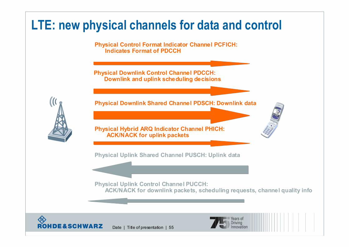
LTE: new physical channels for data and control
Physical Downlink Control Channel PDCCH:Downlink and uplink scheduling decisions
Physical Downlink Shared Channel PDSCH: Downlink data
Physical Control Format Indicator Channel PCFICH:Indicates Format of PDCCH
Physical Hybrid ARQ Indicator Channel PHICH:ACK/NACK for uplink packets
Physical Uplink Control Channel PUCCH:ACK/NACK for downlink packets, scheduling requests, channel quality info
Physical Uplink Shared Channel PUSCH: Uplink data

Date | Title of presentation | 56
LTE Downlink: Downlink Physical Channels
- Physical Downlink Shared Channel, PDSCH: � Used for data transfer, shared principle, variable modulation
� Mapping between DL-SCH and PCH
� MBMS information can be mapped
- Physical Downlink Control Channel, PDCCH� specific control information, shared principle, fixed modulation QPSK
� Carries scheduling decision from eNodeB
� Informs UE about resource allocation fo PCH and DL-SCH
� HARQ information related to DL-SCH
� UL scheduling grant
� Mapped to 2-4 symbols in case of less than 10 RB
� Mapped to 1-3 symbols in case of bigger than 10 RB
- Common Control Physical Channel, CCPCH� General control information, broadcast principle, fixed modulation QPSK
- Physical Multicast Channel, PMCH� Like PDSCH, but no transmit multiplexing

Date | Title of presentation | 57
LTE Downlink: Downlink Physical Channels
- Physical control format indicator channel, PCFICH : � The physical control format indicator channel carries information about the number of
OFDM symbols (1-3 or 2-4) used for transmission of PDCCHs in a subframe. Only
QPSK.
� Transferred in every sub-frame
- Physical HARQ Indicator Channel, PHICH� The PHICH carries the hybrid-ARQ ACK/NAK, fixed modulation QPSK
- Physical Broadcast Channel PBCH� General control information, broadcast principle, fixed modulation QP나� MIB (Master Information Block) Transmission
� 4 subframes within a 40ms interval
� 40 ms timing is blindly detected

Date | Title of presentation | 58
LTE Uplink: Uplink Physical Channels
- Physical Uplink Shared Channel, PUSCH• For user data, shared scheduling principle, variable modulation scheme: QPSK, 16-
QAM, 64-QAM. Timing similar to downlink
- Physical Uplink Control Channel, PUCCH• For uplink control information, never transmit simultaneous to PUSCH. Frequency
and time multiplexed, fixed modulation scheme: QPSK.

Date | Title of presentation | 59
LTE Physical Layer:OFDMA in downlink

Date | Title of presentation | 60
LTE Downlink:How does the OFDMA signal look like?
…
Sub-carriersFFT
Time
Symbols
5 MHz Bandwidth
Guard I ntervals
…
Frequency
� Each sub-carrier (frequency channel) carries a separate low-rate stream of data
� Frequencies are chosen so that the modulated data streams are orthogonal to each other
� Each sub-carrier is independently modulated
� A guard time is added to each symbol (cyclic prefix in LTE)
� Symbol duration is relatively long compared to channel delay spread -> less intersymbol interference

Date | Title of presentation | 61
LTE Downlink:OFDMA Time/Frequency Representation
OFDM symbols (time domain)
Sub carriers (frequency domain)
0
0
1 LTE slot of 0.5 ms =
6 / 7 OFDM symbols dep. on cyclic prefix length
(3 symbols for 7.5 kHz spacing / MBMS scenarios)
• Sub-carrier spacing in LTE = 15 kHz
(7.5 kHz for MBMS scenarios)
• Data is allocated in multiples of resource blocks
• 1 resource block spans 12 sub-carriers in the
frequency domain and 1 slot in the time domain
• Resource block size is identical for all bandwidths
1 LTE Resource Block =
12 sub-carriers
Normal scenario: carrier
spacing of 15 kHz
Big cell scenario: 7,5 kHz +
extended guard time
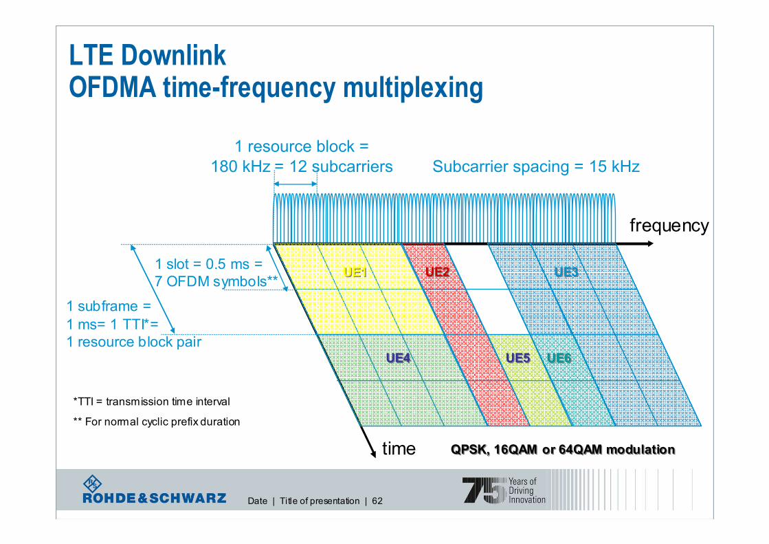
Date | Title of presentation | 62
time
frequency
1 resource block =
180 kHz = 12 subcarriers
1 slot = 0.5 ms =
7 OFDM symbols**
1 subframe =
1 ms= 1 TTI*=
1 resource block pair
LTE DownlinkOFDMA time-frequency multiplexing
*TTI = transmission time interval
** For normal cyclic prefix duration
Subcarrier spacing = 15 kHz
QPSK, 16QAM or 64QAM modulationQPSK, 16QAM or 64QAM modulation
UE1UE1
UE4UE4
UE3UE3UE2UE2
UE5UE5 UE6UE6

Date | Title of presentation | 63
LTE – spectrum flexibility
l LTE physical layer supports any bandwidth from 1.4 MHz
to 20 MHz in steps of 180 kHz (resource block)
l Current LTE specification supports only a subset of 8
different system bandwidths
l All UEs must support the maximum bandwidth of 20 MHz
Transmission
Bandwidth [RB]
Transmission Bandwidth Configuration [RB]
Channel Bandwidth [MHz]
Resource block
Channel e
dge
Channel edge
DC carrier (downlink only)Active Resource Blocks
100755025[16][TBD][7][TBD]TDD mode
100755025n/a15 n/a6FDD mode
20151053.23 1.61.4
Channel
bandwidth
BWChannel
[MHz]
number of resource blocks

Date | Title of presentation | 64
LTE Downlink:Downlink slot and (sub)frame structure
Ts = 32.522 ns
#0 #0 #1 #1 #2 #2 #3 #3 #19 #19
One slot, T slot = 15360 × T s = 0.5 ms
One radio frame, T f = 307200 × T s = 10 ms
#18 #18
One subframe
We talk about 1 slot, but the minimum resource is 1 subframe = 2 slots !!!!!
( )2048150001s ×=T
Symbol time, or number of symbols per time slot is not fixed

Date | Title of presentation | 65
LTE Downlink:baseband signal generation
OFDM
Mapper
OFDM signal
generationLayer
Mapper
Scrambling
Precoding
Modulation
Mapper
Modulation
Mapper
OFDM
Mapper
OFDM signal
generationScrambling
code words layers antenna ports
Avoid
constant
sequences
QPSK
16 QAM
64 QAM
For MIMO
Split into
Several
streams if
needed
Weighting
data streams
for MIMO
1 OFDM
symbol per
stream
1 stream =
several
subcarriers,
based on
Physical
ressource
blocks

Date | Title of presentation | 66
LTE Downlink: Bandwidth agnostic L1
Will be defined by RAN4
One downlink slot, Tslot
One resource block,
NRBsubcarriers
subcarriers
NBW
DL
subcarriers
NBW
DL
NBW
DL
Resource element
OFDM symbolsDLsymbN OFDM symbolsDLsymbN
RBBW
DLBW
RBBW 1106 NNN ×≤≤×
DLBWN
4324
86
Extended cyclic
prefi x
97
12
Normal cyclic prefi x
Frame structure t ype 2Frame structure t ype 1
Configuration
DLsymbNDL
symbN
kHz 15=∆f
kHz 15=∆f
kHz 5.7=∆f
Effective bandwidth is a multiple of
physical ressource block, i.e. 12 * 15kHz or 24 * 7,5 kHz
RB
BWN

Date | Title of presentation | 67
LTE Downlink: Resource-element Groups(REG)
� Basic unit for mapping of PDCCH, PHICH,
PCFICH
� Resource-element groups are used for defining
the mapping of control channels to resource
element
� Mapping of a symbol-quadruplet <z(i),
z(i+1),z(i+2),z(i+3)> onto a REG is defined such
that elements z(i) are mapped to resource
elements (k,l) of the REG not used for cell-specific
reference signals in creasing order of i and k

Date | Title of presentation | 68
Modulation
QPSK, 16QAM, 64QAMPDSCH
QPSK, 16QAM, 64QAMPMCH
Modulation schemesPhysical channel
QPSKPBCH
Modulation schemesPhysical channel
QPSKPCFICH
Modulation schemesPhysical channel
QPSKPDCCH
Modulation schemesPhysical channel
BPSKPHICH
Modulation schemesPhysical channel
Date | Title of presentation | 69
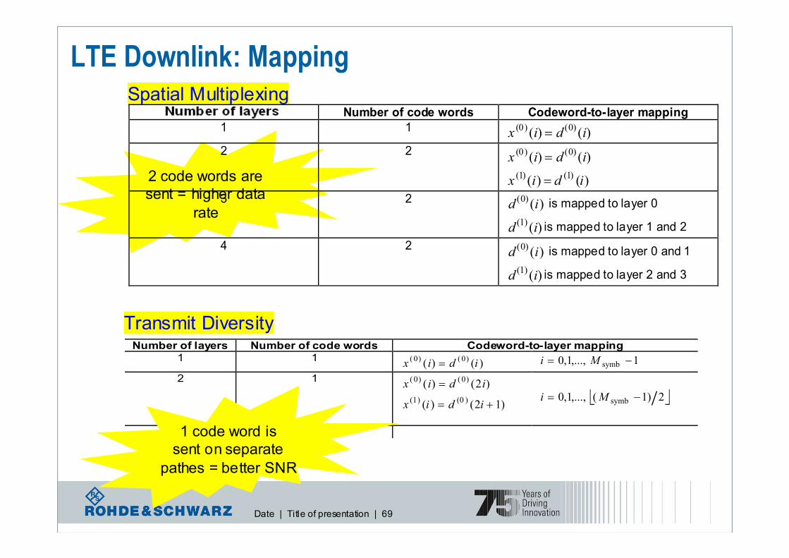
LTE Downlink: Mapping
Transmit DiversityNumber of layers Number of code words Codeword-to-layer mapping
1 1 )()(
)0()0(idix = 1,...,1,0 symb −= Mi
2 1
)12()(
)2()(
)0()1(
)0()0(
+=
=
idix
idix
2)1(,...,1,0 symb −= Mi
4 1
Spatial Multiplexing
2 code words are
sent = higher data
rate
1 code word is
sent on separate
pathes = better SNR
Transmission rank Number of code words Codeword-to-layer mapping
1 1 )()()0()0(idix =
2 2 )()(
)0()0(idix =
)()()1()1(idix =
3 2 )()0(id is mapped to layer 0
)()1(id is mapped to layer 1 and 2
4 2 )(
)0(id is mapped to layer 0 and 1
)()1(id is mapped to layer 2 and 3

Date | Title of presentation | 70
LTE Downlink: Precoding
Number of antenna ports
Transmission rank
Codebook
P ρ
1 1 [ ]1 - - - - -
1
0
1
1
0
1
1
2
1
−1
1
2
1
j
1
2
1
− j
1
2
1
2
2
10
01
2
1
−11
11
2
1
− jj
11
2
1 - - -
1 2
3 4
4
Precoding base on cyclic delay diversity, UE proposes which
Codebook entry shall be selected by transmitter

Date | Title of presentation | 71
LTE Downlink: Downlink Reference Signals
� Downlink reference signal(s) can be used for
� Downlink-channel-quality measurements
� Downlink channel estimation for coherent demodulation/detection at the UE
� Cell search and initial acquisition (carries cell ID)
Of course, there will be reference signals
� Cell-specific reference signals, associated with non-MBSFN transmission
� MBSFN reference signals, associated with MBSFN transmission
� UE-specific reference signals (supported in frame structure type 2 only)

Date | Title of presentation | 72
LTE Downlink: Cell-specific Ref. Signals■ Normal and extended CP
� 504 unique Cell ID
• 168(N1) Cell ID group, 3(N2) Cell ID within each group
• Cell ID = 3xN1+N2 = 0~503 index
� 504 pseudo-random sequences
� One to one mapping between the Cell ID and Pseudo-random sequences
� Transmit on antenna port {0,1,2,3}
� Cell-specific Frequency Shift (N1 mod 6) (effective with RS boosting)
• 1 RE shift from current RS position in case of next Cell ID index
■ Pseudo-random sequence generation
� ns is the slot number within a radio frame
� l is the OFDM symbol number within the slot
� The pseudo-random sequence c(i) is a length-31 Gold sequence
( ) ( ) 11210 ,)12(212
1)2(21
2
1)( PDSCH
RB, −=+⋅−+⋅−= N,...,,mmcjmcmrsnl
( )( ) ( ) CPcellID
cellIDs NNNlnc +⋅++⋅⋅+++⋅⋅= 212117210init
(2)ID
(1)ID
cellID 3 NNN +=

Date | Title of presentation | 73
LTE Downlink, Common Control physical channel:Downlink Reference Signals - mapping
R0
R0
R0
R0
R0
R0
R0
R0
0=l 6=l 0=l 6=l
R0
R0
R0
R0
R0
R0
R0
R0
0=l 6=l 0=l 6=l
R1
R1
R1
R1
R1
R1
R1
R1
0=l 6=l 0=l 6=l
even-numbered slots odd-numbered slots
R3
R3
R3
R3
0=l 6=l 0=l 6=l
R0
R0
R0
R0
even-numbered slots odd-numbered slots
R0
R0
R0
R0
0=l 6=l 0=l 6=l
R1
R1
R1
R1
even-numbered slots odd-numbered slots
R1
R1
R1
R1
0=l 6=l 0=l 6=l
even-numbered slots odd-numbered s lots
R2
R2
R2
R2
0=l 6=l 0=l 6=l
One antenna port
Two antenna ports
Four antenna ports
Antenna port 0 Antenna port 1 Antenna port 2 Antenna port 3
Not used for transmission on this antenna port
Reference symbols on th is antenna por t
( )lk,element Resource
1 antenna configuration
2 antenna configuration
4 antenna configuration
Pilots are place
that each antenna
can be recognised

Date | Title of presentation | 74
LTE Downlink: Hopping/Boosting for DL RS
■ Cell-specific frequency hopping or shifting (FH/FS) is supported ���� No hopping
� The mode of operation in a cell is static
� FH/FS sequence acquired from cell group ID (FH/FS per sub-frame)
• There is one-to-one mapping between the RS hopping sequence and the two-dimensional PRBS
� Blind detection of hopping mode and non-hopping mode by UE
■ RS power Boosting
�Motivation : provisioning of enough RS power to the cell edge UEs
� Boosting of all of the unicast RS
� By the NodeB configuration, puncturing can be applied (UE is informed by system
information) to data subcarriers in the same OFDM symbol
Date | Title of presentation | 75
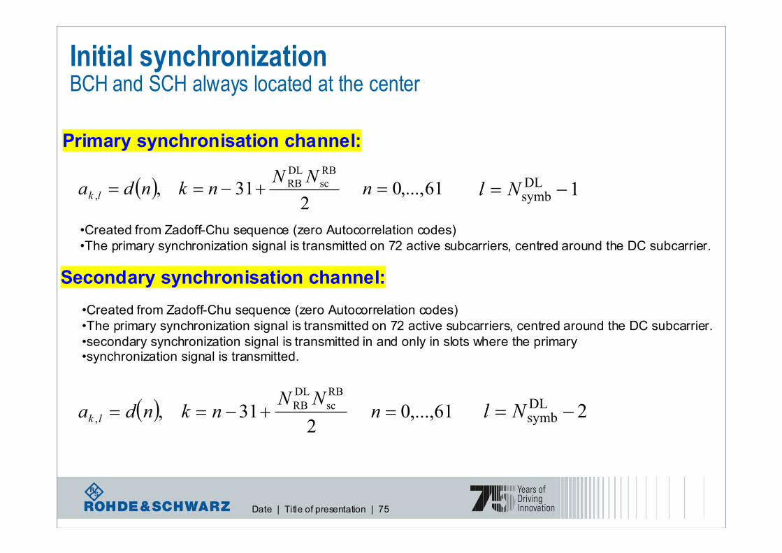
Initial synchronizationBCH and SCH always located at the center
Primary synchronisation channel:
Secondary synchronisation channel:
•Created from Zadoff-Chu sequence (zero Autocorrelation codes)
•The primary synchronization signal is transmitted on 72 active subcarriers, centred around the DC subcarrier.
•Created from Zadoff-Chu sequence (zero Autocorrelation codes)
•The primary synchronization signal is transmitted on 72 active subcarriers, centred around the DC subcarrier.
•secondary synchronization signal is transmitted in and only in slots where the primary •synchronization signal is transmitted.
2DLsymb −= Nl
1DLsymb −= Nl( ) 61,...,0
231 ,
RB
sc
DL
RB, =+−== n
NNnknda lk
( ) 61,...,0 2
31 ,
RB
sc
DL
RB
, =+−== nNN
nknda lk

Date | Title of presentation | 76
Initial synchronization : PSS
■ The sequence for the PSS is generated from a freq.-domain Zadoff-Chu sequence (Length-62)
=
== ++−
+−
61,...,32,31
30,...,1,0)(
63
)2)(1(
63
)1(
ne
nend
nnuj
nunj
u π
π
■ Background of Zadoff-Chu Sequence
� Appeared in IEEE Trans. I in 1972
� Poly-phase sequence
� Cyclic autocorrelations are zero for all non-zero lags Non-zero cross-correlations
� PAPR이낮아 (신호의 Amplitude 일정) 전력소모적측면에서유리
� CAZAC (Constant Amplitude Zero Auto Correlation) Sequence의일종
{ }2,1,0)2(ID ∈N
)(21)(~ ixic −= 300 ≤≤ i
( ) 250 ,2mod)()3()5( ≤≤++=+ iixixix
)31mod)3((~)(
)31mod)((~)(
)2(
ID1
)2(
ID0
++=
+=
Nncnc
Nncnc
<TS 36.211 / Table 6.11.1.1-1>

Date | Title of presentation | 77
Initial synchronization : SSS
■ The sequence for the PSS is an interleaved concatenation of two m-sequence (length 31)
■ The concatenated sequence is scrambled with a scrambling sequence given by PSS
■ 2 m-sequences are differ between subframe 0 and subframe 5
( )( )( ) ( )( ) ( )
=+
=
5 subframein )(
0 subframein )()12(
5 subframein )(
0 subframein )()2(
)(11
)(0
)(11
)(1
0)(
1
0)(
0
10
01
1
0
nzncns
nzncnsnd
ncns
ncnsnd
mm
mm
m
m
)31mod)3((~
)(
)31mod)((~
)(
)2(ID1
)2(ID0
++=
+=
Nncnc
Nncnc ( )( )31mod)(~
)(
31mod)(~
)(
1)(
1
0)(
0
1
0
mnsns
mnsns
m
m
+=
+=
)31mod))8mod(((~)( 0)(
10 mnznz
m +=
)31mod))8mod(((~)( 1)(
11 mnznzm +=
<TS 36.211 / Table 6.11.2.1-1>

Date | Title of presentation | 78
LTE Downlink: BCH■ Primary BCH
�Master information block of system information is transmitted on Primary BCH
• L1 parameters (e.g. DL system BW[4bits], etc…
• System frame Number (SFN)
• PHICH duration (1bit)
• PHICH resource (2bits)
• Etc…
■ Dynamic BCH
� After successful reception of PBCH, UE can read D-BCH in PDSCH (including PCFICH and PDCCH) which carries system information not included in PBCH
• Uplink information (uplink bandwidth, uplink RS configuration and TX power
• PRACH information (time/freq-domain configuration, preamble format, root sequence index, zerocorrelation zone length, high-speed flag, power setting, RA-RNTI)
• Sounding reference signal information (subframes with SRS transmission)
• PUCCH, PUSCH information (base sequence group, hopping pattern, …)
• One or more PLMN identities and related information
• Tracking Area Code
• Cell Identity
• Number of transmit antennas
• RS transmit power
• Etc…

Date | Title of presentation | 79
LTE Downlink: BCH
■ The coded BCH transport block is mapped to four subframes (slot#1 in subframe #0)
■ BCH mapped to 4 OFDM symbols within a subframe
■ Each subframe is assumed to be self-decodable, i.e. the BCH can be decoded from a signal
reception, assuming sufficiently good channel conditions
■Single (fixed-size) transport block per TTI (40ms)
� No HARQ
� Cell-specific scrambling, BPSK with ½ tail-biting Conv. Code, TX diversity(1,2,4)
� 6RBs = 72 subcarries (excluding DC)
■ PBCH is mapped into RE assuming RS from 4 antennas are used at eNB, irrespective of the actual
number of TX antenna
■ Different transmit diversity schemes per # of antennas
� # of ant=2 : SFBC
� # of ant=4 : SFBC + FSTC (Frequency Switching Transmit Diversity)
■ No explicit bits in the PBCH to signal the number of TX antennas at eNB
� PBCH encoding chain includes CRC masking dependent on the number of configured TX antennas at eNB
� Blind detection of the number of TX antenna using CRC masking by UE

Date | Title of presentation | 80
LTE DownlinkConfiguration of synchronization signals
10 ms radio frame
1 2 3 4 5 6 7 1 2 3 4 5 6 7
0.5 ms slot
1 ms subframe
Primary synchronization signal
Secondary synchronization signal
Screenshot of R&S SMU200A signal generator

Date | Title of presentation | 81
LTE DownlinkConfiguration of physical broadcast channel
10 ms radio frame
1 2 3 4 5 6 7 1 2 3 4 5 6 7
0.5 ms slot
1 ms subframe
Primary synchronization signal
Secondary synchronization signalPhysical Broadcast Channel (PBCH)
PBCH has 40 ms transmission time interval

Date | Title of presentation | 82
LTE downlinkSynchronization and reference signals, PBCH
50 resource
blocks in 10 MHz
10 subframes = 140 OFDM symbols
Screenshot of R&S
SMU200A signal generator
Date | Title of presentation | 83
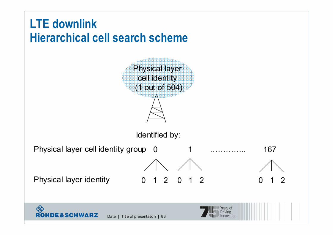
LTE downlinkHierarchical cell search scheme
0 1 ………….. 167
Physical layer identity 0 1 20 1 20 1 2
Physical layer cell identity group
identified by:
Physical layer
cell identity
(1 out of 504)

Date | Title of presentation | 84
LTE DownlinkCell search procedure
1. Primary synchronization signal:
3 possible sequences to identify the cell’s physical layer identity (0, 1, 2)
Transmitted every 5 ms to identify 5 ms timing
2. Secondary synchronization signal:
168 different sequences to identify physical layer cell identity group
Transmitted every 5 ms to identify radio frame timingDownlink
reference signal
3. Physical broadcast channel (PBCH):
Carrying broadcast channel with predefined information:
system bandwidth, number of transmit antennas, reference
signal transmit power, system frame number,…
Physical layer
cell identity
(1 out of 504)

Date | Title of presentation | 85
Initial synchronizationBCH and SCH always located at the center
20MHz bandwidth
SCH
10 MHz bandwidth
1.25 MHz bandwidth
BCH

Date | Title of presentation | 86
CAZAC sequence – constellation diagramConstant Amplitude Zero Auto Correlation

Date | Title of presentation | 87
Constellation Display (DL FDD, 10 MHz) I
QPSK-modulated user data
Date | Title of presentation | 88
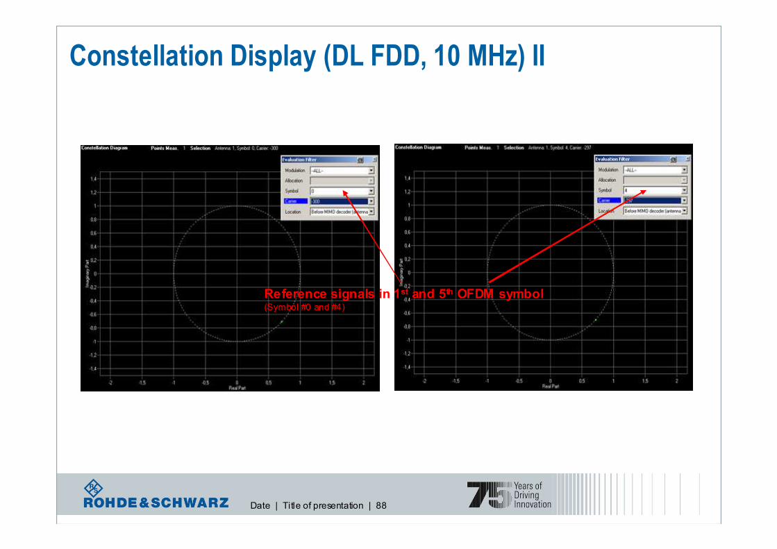
Constellation Display (DL FDD, 10 MHz) II
Reference signals in 1st and 5th OFDM symbol (Symbol #0 and #4)
Date | Title of presentation | 89
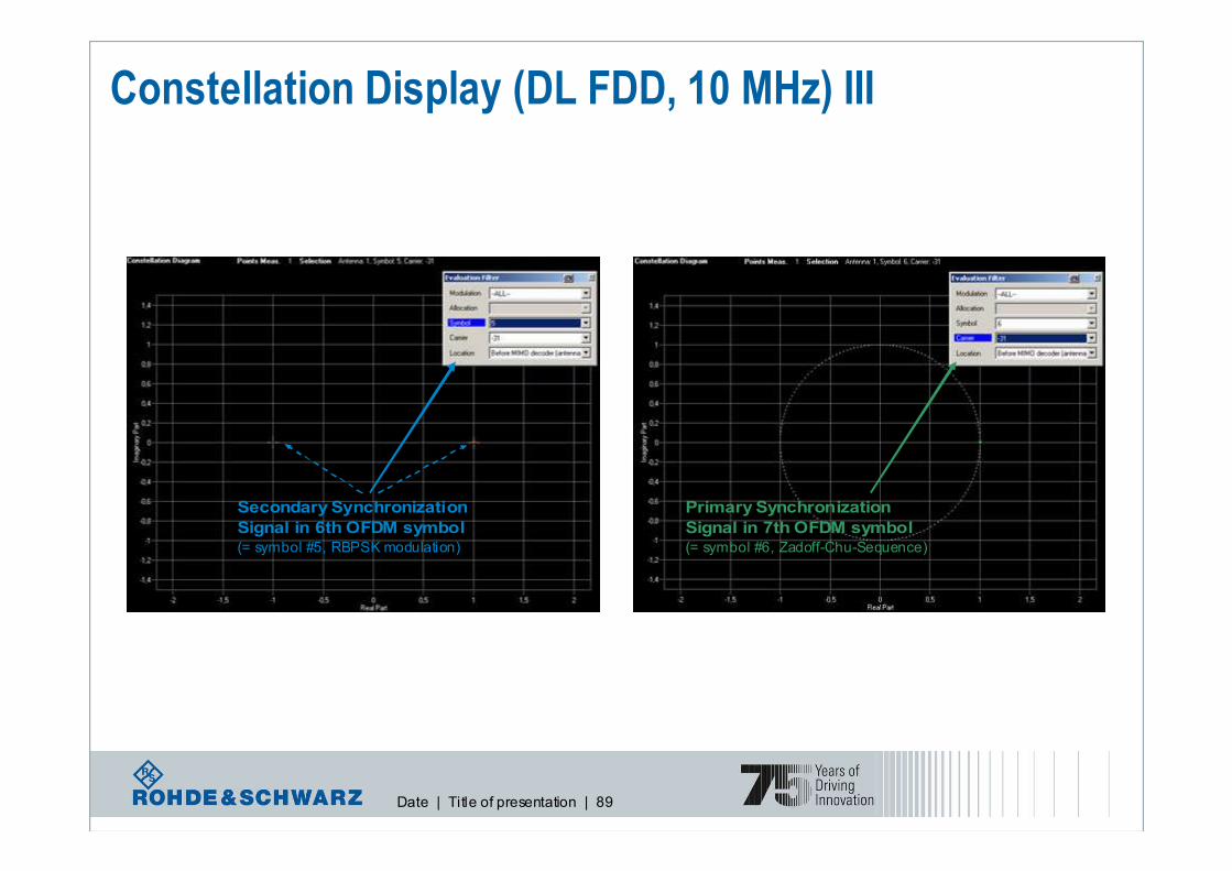
Constellation Display (DL FDD, 10 MHz) III
Secondary Synchronization
Signal in 6th OFDM symbol(= symbol #5, RBPSK modulation)
Primary Synchronization
Signal in 7th OFDM symbol(= symbol #6, Zadoff-Chu-Sequence)

Date | Title of presentation | 90
LTE Downlink: PCFICH
■ The number of OFDM symbols used for control channel is variable
■ TTI마다바뀔수 있음
■ CFI (Control Format Indication)
■ Information about the number of OFDM symbols (1~4) used for transmission of PDCCHs in a subframe
■ PCFICH carries CFI
■ Cell-specific scrambling prior to modulation
■ 2 info bits � Coding rate of 1/16 � Number ofo bits = 32bits
■Modulation : QPSK
■Mapping to resource elements : 4REG (16 RE excluding RS) in the 1st OFDM symbol
■ Spread over the whole system bandwidth
■ Same mapping for 1,2 and 4 antennas
3GPP TS 36.212 / Table 5.3.4-1: CFI codewords
<0,0,0,0,0,0,0,0,0,0,0,0,0,0,0,0,0,0,0,0,0,0,0,0,0,0,0,0,0,0,0,0>4 (Reserved)
<1,1,0,1,1,0,1,1,0,1,1,0,1,1,0,1,1,0,1,1,0,1,1,0,1,1,0,1,1,0,1,1>3
<1,0,1,1,0,1,1,0,1,1,0,1,1,0,1,1,0,1,1,0,1,1,0,1,1,0,1,1,0,1,1,0>2
<0,1,1,0,1,1,0,1,1,0,1,1,0,1,1,0,1,1,0,1,1,0,1,1,0,1,1,0,1,1,0,1>1
CFI codeword < b0, b1, …, b31 >CFI
<10 RB : 2~4 OFDMA symbols
>10RB : 1~3 OFDMA symbols

Date | Title of presentation | 91
LTE Downlink: PDCCH
■ First n OFDM symbols
■ <10 RB : 2~4 OFDMA symbols
■ >10RB : 1~3 OFDMA symbols
■ Scheduling assignment
■ Transport format, resource allocation, HARQ info related to DL-SCH, PCH
■ Transport format, resource allocation, HARQ info related to UL-SCH
■ DPCCH format based on # of CCE (Control Channel Element = 9 REGs) used
3GPP TS 36.211 / Table 6.8.1-1: Supported PDCCH formats
576
288
144
72
Number of PDCCH bits
7283
3642
1821
910
Number of REGsNumber of CCEsPDCCH format
■ Cell-specific scrambling, QPSK with tail-biting Conv. Code
■ TX diversity, the same antenna ports as PBCH
■ Mapped to REG no assigned to PCFICH or PHICH

Date | Title of presentation | 92
LTE Downlink: PDCCH
■ DCI transports downlink or uplink scheduling information, or uplink power control commands
For the transmission of TPC commands for PUCCH and PUSCH with single bit power
adjustment3A
For the transmission of TPC commands for PUCCH and PUSCH with 2-bit power
adjustment3
For scheduling PDSCH to use configured in open-loop SM2A
For scheduling PDSCH to use configured in closed-loop SM2
For the compact scheduling of one PDSCH codeword with precoding and power offset
information1D
For very compact scheduling of one PDSCH codeword (paging, RACH response and
dynamic BCCH scheduling)1C
For the compact scheduling of one PDSCH codeword with precoding information
(closed-loop single-rank)1B
For the compact scheduling of one PDSCH codeword (SIMO, TxD)1A
For the scheduling of one PDSCH codeword (SIMO, TxD)1
For the scheduling of PUSCH0
DescriptionDCI Formats

Date | Title of presentation | 93
PDCCH layer 1/2 control channel contentsUplink scheduling grant (DCI format 0)
� Hopping flag – 1 bit
� Resource block assignment and hopping resource allocation
� Modulation and coding scheme, redundancy version – 5 bits
� New data indicator – 1 bit
� TPC command for scheduled PUSCH – 2 bits
� Cyclic shift for demodulation reference signal – 3 bits
� Uplink index for TDD - 2 bits
� CQI request – 1 bit

Date | Title of presentation | 94
PDCCH layer 1/2 control channel contentsDownlink scheduling assignment (DCI format 2)
� Resource allocation header (allocation type 0 or 1) – 1 bit
� Resource block assignment
� TPC command for PUCCH and persistent PUSCH – 2 bits
� Downlink assignment index for TDD – 2 bits
� Number of layers – 2 bits
� HARQ process number – 3 bits (FDD), 4 bits (TDD)
� Transport block to code word swap flag – 1 bit
� Precoding information and confirmation
For the first codeword:
� Modulation and coding scheme – 5 bits
� New data indicator – 1 bit
� Redundancy version – 2 bits
For the second codeword:
�Modulation and coding scheme – 5 bits
�New data indicator – 1 bit
�Redundancy version – 2 bits

Date | Title of presentation | 95
LTE Downlink: PHICH
■ HARQ ACK/NACK in response to UL transmission
■ PHICH group
■ Multiple PHICHs mapped to the same set of REs (CDM & I/Q)
■ HI codewords with length of 12 Res = 4 (spreading) X 3 (repetition)
■ Orthogonal sequence : Walsh
■ BPSK Modulation with I/Q multiplexing
■ SF4 X I/Q = 8 PHICHs in normal CP
■ SF4 X I/Q = 4 PHICHs in extended CP
■ Cell-specific scrambling
■ TX diversity, the same antenna ports as PBCH
■ 3 groups of 4 contiguous REs (not used for RS and PCFICH)
3GPP TS36.811 / Table 6.9.1-2: Orthogonal sequences for PHICH
3GPP TS36.812 / Table 5.3.5-1: HI codewords
< 1,1,1 >1
< 0,0,0 >0
HI codeword
< b0, b1, b2 >HI

Date | Title of presentation | 96
LTE DownlinkConfiguration of physical broadcast channel

Date | Title of presentation | 97
Physical Downlink SharedChannel (PDSCH)
I would like to receive data on
PDSCH but I don‘t know which
resource blocks are allocated for meand how they look like
?
Physical Downlink ControlChannel (PDCCH)
Check PDCCH for your UE ID. As soon as you are addressed, you will
find all the information you need there.
LTE downlinkScheduling of downlink data

Date | Title of presentation | 98
I would like to read the PDCCH butwhere is it?
?
Physical Control Format
Indicator Channel (PCFICH)
Check PCFICH. It will tell you how manysymbols (1, 2, or 3)in the beginning of the
subframe are allocated for PDCCH.
Physical Control Format Indicator Channel (PCFICH) Indicating PDCCH format
Physical Downlink Control
Channel (PDCCH)

Date | Title of presentation | 99
Physical Hybrid ARQ Indicator Channel (PHICH) Acknowledging uplink data packets
Physical Uplink Shared Channel
(PUSCH)
I have sent data packets on PUSCHbut I don‘t know whether they have
been received correctly.
?
Physical Hybrid ARQ
Indicator Channel (PHICH)
Read the PHICH. It carries ACK orNACK for each single packet.

Date | Title of presentation | 100
LTE Physical Layer:SC-FDMA in uplink

Date | Title of presentation | 101
LTE Uplink:How to generate an SC-FDMA signal in theory?
� LTE provides QPSK,16QAM, and 64QAM as uplink modulation schemes
� Each subcarrier carries a portion of superposed DFT spread data symbols
� CAZAC (Constant Amplitude Zero Autocorrelation) sequence 사용
� Ref. signal 및제어정보채널전송시각단말들의신호를구분하기위해CDM을수행하는경우,
CAZAC sequence를주로사용
� CAZAC sequence는 time/freq. domain에서일정한 amplitude를유지하는특성을가지므로단말의 PAPR을낮추어커버리지를증가시키기에적합함
� MU-MIMO 지원
DFT Sub-carrier Mapping
CP insertion
Size-NTX Size-NFFT
Coded symbol rate= R
NTX symbols
IFFT

Date | Title of presentation | 102
LTE Uplink:How does the SC-FDMA signal look like?
� In principle similar to OFDMA, BUT:
� In OFDMA, each sub-carrier only carries information related to one specific symbol
� In SC-FDMA, each sub-carrier contains information of ALL transmitted symbols
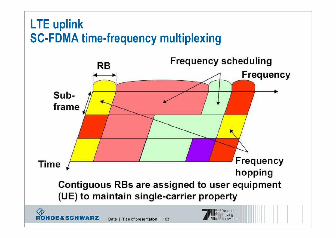
Date | Title of presentation | 103
LTE uplinkSC-FDMA time-frequency multiplexing

Date | Title of presentation | 104
LTE Uplink: SC-FDMA parametrization for PUSCH and PUCCH, slot format
One uplink slot, T slot
2 1 0
Modulation symbol
2 UL symb − N 1 UL
symb − N
2 , UL symb − N u a

Date | Title of presentation | 105
LTE Uplink: Physical Channels in uplink� Physical Uplink Shared Channel, PUSCH
� Uplink data with localized transmission (with/without hopping)
� Frequency hopping is available on both slot basis and subframe basis
� Physical Uplink Control Channel, PUCCH� Carries HARQ ACK/NACK in response to DL transmission
� Carries Scheduling Request (SR), CQI, PMI and RI
� PUCCH transmission
� Physical Random Access Channel, PRACH
� Carries the random access preamble
� UCI transmission with PUSCH
� CQI/PMI is multiplexed with PUSCH and mapped into PUSCH bands
� ACK/NAK is multiplexed with PUSCH by punchuring the data
� RS would be transmitted through RRC Signalling (RAN2)
� UL Signal� An uplink physical signal is used by the physical layer but does not carry information originating from
higher layers
� UL RS (Uplink Reference Signal) for PUSCH, PUCCH
� UL Sounding RS not associated with PUSCH, PUCCH transmission
※ Can’t send PUSCH/PUSCCH at same time

Date | Title of presentation | 106
LTE Uplink: Reference Signals
� DM RS
� Uplink channel estimation for uplink coherent demodulation/detection
� CAZAC sequence로생성
� Normal CP = 4th symbol / Extended CP = 3rd symbol
� Inter-cell Interference를완화하기위해 Group hopping/Sequence Hopping 적용
� Group hopping :
� Base seq. group index값이 slot단위로변화
� 17개의 hopping pattern마다 30개의Group hopping Index (shift pattern)
� Seq. hopping :
� DM RS의길이가 5RB보다큰경우, 한한한한 sub-frame내에서내에서내에서내에서 slot단위로단위로단위로단위로 Base seq. index간간간간hopping이이이이 이루어짐이루어짐이루어짐이루어짐
� Sounding RS
� uplink channel-quality estimation for better scheduling decisions
� PUxCH와 무관
� SRS 전송주기/서브프레임/대역폭은 각단말마다 고유하게할당 (최소 4RB)
� SRS는 subframe의 마지막 SC-FDMA symbol로전송
� Not used yet

Date | Title of presentation | 107
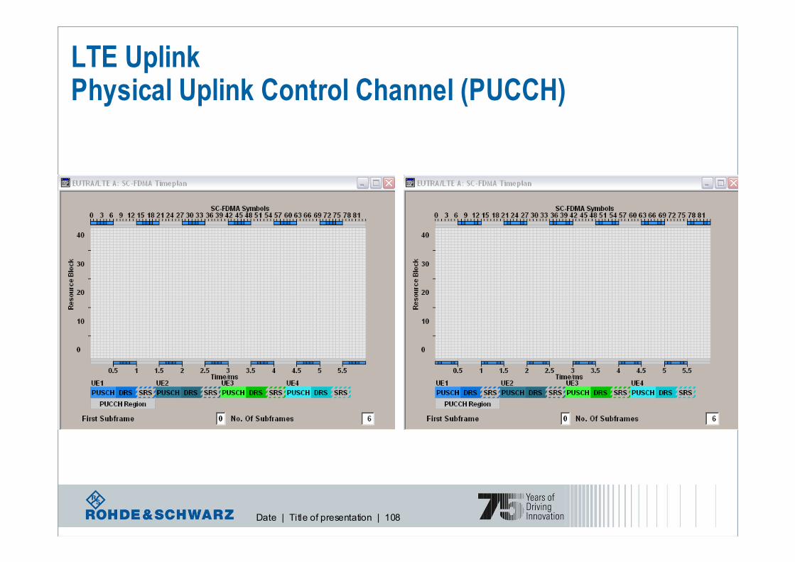
LTE Uplink : Physical Uplink Control Channel (PUCCH)
frequency
1 ms subframe
resource i
resource i
resource j
resource j
� PUCCH is never transmitted simultaneously with PUSCH from the same UE
� Only needed when there is no PUSCH available
� Carries Uplink Control Information (UCI) in PUCCH or PUSCH
� Carries ACK/NACK, CQI, PMI, RI and SR (Scheduling Request)
� Symbol mapping of BPSK or QPSK
� 2 consecutive PUCCH slots in Time-Frequency Hopping at the slot boundary
Date | Title of presentation | 108
LTE UplinkPhysical Uplink Control Channel (PUCCH)

Date | Title of presentation | 109
LTE Uplink : PUSCH Frequency Hopping
� PUSCH Transmission
� 1 bit indication in UL grant whether frequency hopping or not (in DCI format=0 / hopping bit=1)
� Localized transmission w/o frequency hopping
Frequency Selective Scheduling Gain
� Localized transmission with frequency hopping
Frequency Diversity Gain, Inter-cell Interference Randomization
Hopping based on the hopping information in UL grant (type 1 – according to hopping bits)
Hopping according to a predefined hopping pattern (type 2 - according to hopping pattern)
� Transmission and hopping modes are given from UL scheduling grant
� Inter subframe / Intra subframe PUSCH hopping (related to UE mobility)
� Set of PRBs (for PUSCH) to be used for transmission are given by scheduling grant
If hopping with predefined hopping pattern is enabled, a predefined pattern is used together
� When grant is absent, e.g., in cases of persistent scheduling and HARQ retransmission, UE follows the
indication for hopping mode in the initial grant (with RACH)
� A single bit signalled by higher layer indicates whether PUSCH frequency hopping is inter-subframe
only or both intra and inter-subframe

Date | Title of presentation | 110
50 resource
blocks in 10 MHz
Demodulation pilot signal
Screenshot of R&S SMU200A
signal generator
LTE UplinkPhysical Uplink Shared Channel (PUSCH)

Date | Title of presentation | 111
LTE Uplink: Resource allocation

Date | Title of presentation | 112
LTE Uplink: Random Access Procedure
Higher layers indicate position of random access in frequency/time domain

Date | Title of presentation | 113
LTE Uplink : Random access preamble
CPT SEQT
9Even15
0, 1, 2, 3, 4, 5, 6, 7, 8, 9Any14
1, 3, 5, 7, 9Any13
0, 2, 4, 6, 8Any12
3, 6, 9Any11
2, 5, 8Any10
1, 4, 7Any9
3, 8Any8
2 ,7Any7
1, 6Any6
7Any5
4Any4
1Any3
7Even2
4Even1
1Even0
Subframe numberSystem frame numberPRACH configuration
� PRACH 는 RA 과정에서단말이기지국으로전송하는 Preamble
� 6RB를차지하며 subcarrier는 1.25KHz (Format #4는 7.5KHz)
� Sequence 부분은길이 839의 ZC sequence로구성 (Format#4는길이 139)
� 5 types of preamble formats (Higher layers control the preamble format/configuration)

Date | Title of presentation | 114
LTE Protocol ArchitectureBasic

Date | Title of presentation | 115
Packet Date Convergence Protocol
•compression of redundant protocol control
information(TCP/IP, RTP/UDP/IP headers)
•Transfer of user data(PDCP SDU from NAS) to
RLC
•support of losless relocation of SRNS
Broadcast/Multicast Control Protocol
•Storage of Cell Broadcast Messages.
•Traffic volume monitoring and radio
resource request for CBS.
•Scheduling of BMC messages.
•Transmission of BMC messages to UE.
•Delivery of Cell Broadcast messages to
upper layer (NAS)
Summary of layers

Date | Title of presentation | 116
WCDMA/HSPA
UE UENode-B Node-B RNCRNC
HSDPA HSUPA

Date | Title of presentation | 117
User plane
PDCP = Packet Data Convergence Protocol
RLC = Radio Link Control
MAC = Medium Access ControlPHY = Physical Layer
SDU = Service Data Unit
(H)ARQ = (Hybrid) Automatic Repeat Request
Header compression (ROHC)
In-sequence delivery at handoverDuplicate detection
Ciphering for user/control plane
Integrity protection for control plane
Timer based SDU discard in Uplink…
AM, UM, TM
ARQ
(Re-)segmentation
ConcatenationIn-sequence delivery
Duplicate detection
SDU discard
Reset…
Mapping between logical and
transport channels(De)-Multiplexing
Traffic volume measurements
HARQ
Priority handlingTransport format selection…

Date | Title of presentation | 118
Control plane
EPS = Evolved packet system
RRC = Radio Resource ControlNAS = Non Access Stratum
ECM = EPS Connection Management
Broadcast
Paging
RRC connection setupRadio Bearer Control
Mobility functions
UE measurement control…
EPS bearer management
Authentication
ECM_IDLE mobility handling
Paging origination in ECM_IDLESecurity control…

Date | Title of presentation | 119
LTE Protocol ArchitectureUser and Control Plane
Date | Title of presentation | 120
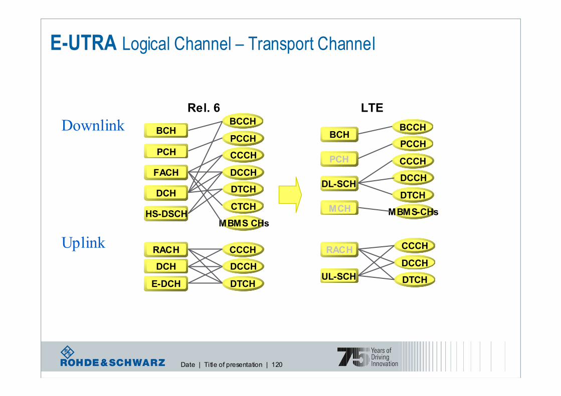
E-UTRA Logical Channel – Transport Channel
Uplink
Downlink
LTE
BCHBCCH
PCH
PCCH
CCCH
DCCH
DTCH
CTCH
MBMS CHs
FACH
DCH
CCCH
DCCH
DTCH
RACH
DCH
BCHBCCH
PCH
PCCH
CCCH
DCCH
DTCH
MBMS-CHs
DL-SCH
MCH
CCCH
DCCH
DTCH
RACH
UL-SCH
HS-DSCH
E-DCH
Rel. 6

Date | Title of presentation | 121
LTE – channels
PRACH PUCCH PUSCH
UL-SCHRACH
DTCHCCCH DCCH
UL logical channels
UL transport channels
UL physical channels

Date | Title of presentation | 122
l Reduced number of transport channels
l Shared channels instead of dedicated channels
l Reduction of Medium Access Control (MAC) entities
l Streamlined concepts for broadcast / multicast (MBMS)
l No inter eNodeB soft handover in downlink/uplink
l No compressed mode
l Reduction of RRC states
LTE Protocol ArchitectureReduced complexity

Date | Title of presentation | 123
Initial access procedure
UE eNB
Random Access Preamble1
Random Access Response 2
Scheduled Transmission3
Contention Resolution 4
Random ID
Sent on DL-SCH;
assignment of Temporary
C-RNTI and initial uplink
grantSent on UL-SCH; includes
NAS UE identifier and RRC CONNECTION REQUEST
Sent on DL-SCH; addressed
to Temporary C-RNTI (early
contention resolution)

Date | Title of presentation | 124
RRC Connection Establishment
RRC CONNECTION SETUP
RRC CONNECTION REQUEST
UE EUTRAN
RRC CONNECTION SETUP COMPLETE

Date | Title of presentation | 125
Initial context establishment

Date | Title of presentation | 126
LTE measurements

Date | Title of presentation | 127
LTE RF Testing AspectsUE requirements according to 3GPP 36.521/523
�Transmitter Characteristics:� Maximum output power
� Frequency error
� Output power dynamics (power control, transmit on/off power,…)
� Output RF spectrum emissions (occupied bandwidth, out of band emissions, spectrum emisssionmaks, ACLR,…)
� Transmit intermodulation
� Modulation quality, EVM� …
TR 36.803: User Equipment (UE) radio
transmission and reception
�Receiver characteristics:� Reference sensitivity level
� Maximum input level
� Adjacent channel selectivity� Blocking characteristics
� Spurious response
� Intermodulation characteristics
� Spurious emissions� …
�Performance

Date | Title of presentation | 128
There will be enough topics
for future trainings ☺
Thank you for your attention!
Comments and questions welcome!