Embed Size (px)
Citation preview
The most important thing we build is trust
PXIUMTS DL Measurement Suite
Data Sheet
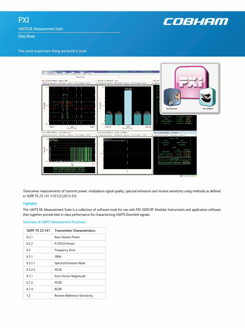
Transceiver measurements of transmit power, modulation signal quality, spectral emissions and receive sensitivity using methods as definedin 3GPP TS 25.141 V10.5.0 (2012-03)
Highlights
The UMTS DL Measurement Suite is a collection of software tools for use with PXI 3000 RF Modular Instruments and application softwarethat together provide best in class performance for characterizing UMTS Downlink signals;.
Summary of UMTS Measurement Functions
3GPP TS 25.141 Transmitter Characteristics
6.2.1 Base Station Power
6.2.2 P-CPICH Power
6.3 Frequency Error
6.5.1 OBW
6.5.2.1 Spectral Emission Mask
6.5.2.2 ACLR
6.7.1 Error Vector Magnitude
6.7.2 PCDE
6.7.4 RCDE
7.2 Receive Reference Sensitivity
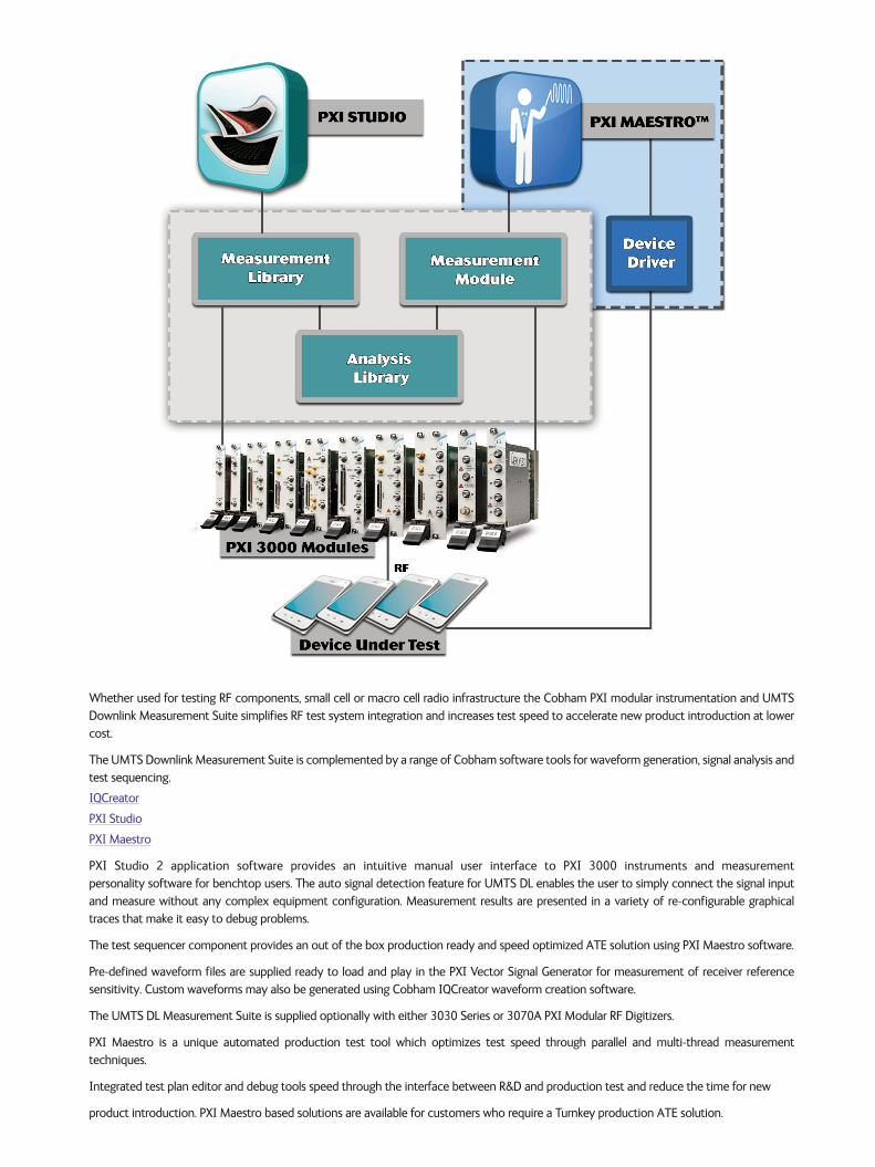
Whether used for testing RF components, small cell or macro cell radio infrastructure the Cobham PXI modular instrumentation and UMTSDownlink Measurement Suite simplifies RF test system integration and increases test speed to accelerate new product introduction at lowercost.
The UMTS Downlink Measurement Suite is complemented by a range of Cobham software tools for waveform generation, signal analysis andtest sequencing.
IQCreator
PXI Studio
PXI Maestro
PXI Studio 2 application software provides an intuitive manual user interface to PXI 3000 instruments and measurement personality software for benchtop users. The auto signal detection feature for UMTS DL enables the user to simply connect the signal inputand measure without any complex equipment configuration. Measurement results are presented in a variety of re-configurable graphicaltraces that make it easy to debug problems.
The test sequencer component provides an out of the box production ready and speed optimized ATE solution using PXI Maestro software.
Pre-defined waveform files are supplied ready to load and play in the PXI Vector Signal Generator for measurement of receiver reference sensitivity. Custom waveforms may also be generated using Cobham IQCreator waveform creation software.
The UMTS DL Measurement Suite is supplied optionally with either 3030 Series or 3070A PXI Modular RF Digitizers.
PXI Maestro is a unique automated production test tool which optimizes test speed through parallel and multi-thread measurement techniques.
Integrated test plan editor and debug tools speed through the interface between R&D and production test and reduce the time for new
product introduction. PXI Maestro based solutions are available for customers who require a Turnkey production ATE solution.
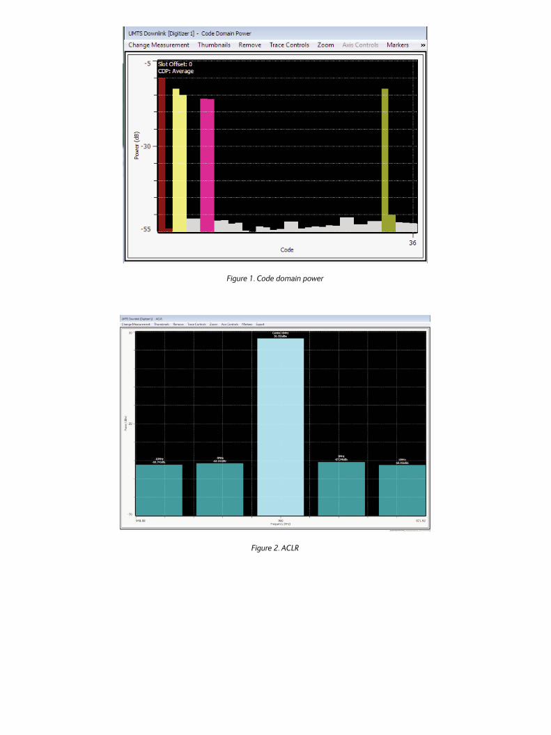
Figure 1. Code domain power
Figure 2. ACLR
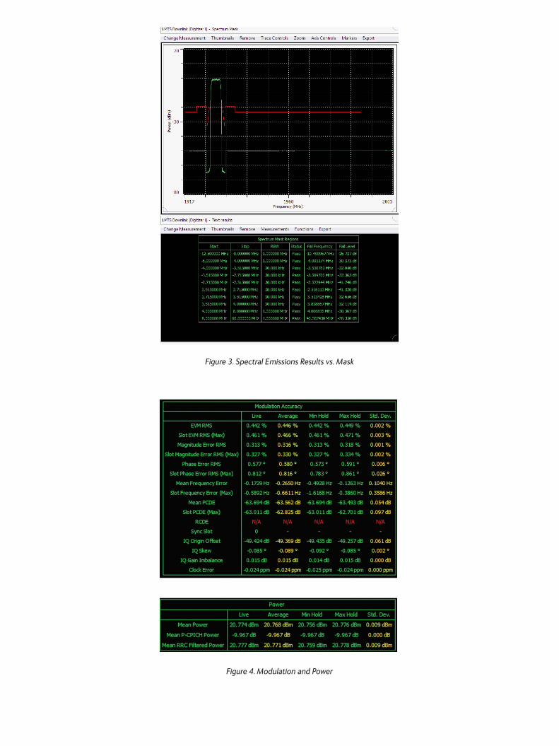
Figure 3. Spectral Emissions Results vs. Mask
Figure 4. Modulation and Power
SPECIFICATION
All specifications are defined when used in conjunction with 3030 Series or 3070A PXI RF Digitizers with option 110 enabled operating in specified UMTS downlink frequency bands. Test sequencing with PXI Maestro additionally requires option 210.
For details of PXI 3000 RF Digitizer specifications refer to the appropriate module specification.
http://ats.aeroflex.com/modular-instrumentation-pxi-products/pxi-systems-solutions/modules
Specifications are defined with input signal at the PXI RF Digitizer tuned frequency and at the reference level unless otherwise stated.
Rx BLER measurement additionally requires a PXI 3000 signal generator module to be assigned configured to support I&Q vector modulation.
MEASUREMENT CONFIGURATION
Frequency
Band Selection: None, I to XXII and XXV (excluding bands XV – XVIII)
Channel Selection: UARFCN or Hz
Level
See RF Digitizer maximum RF input
External Path Loss
0 to 100.00 dB
Detection
UMTS Downlink Test Models as per table below or Auto
Channel Types
Dedicated physical channel (DPCH)
High speed physical downlink shared channel (HS-PDSCH)
Primary common control physical channel (P-CCPCH)
Secondary common control physical channel (S-CCPCH)
Common pilot channel (CPICH)
Shared control channel for HS-DSCH (HS-SCCH)
Page indicator channel (PICH)
Synch Method
SCH or CPICH
Slot Number
0 to 14 or random
Test Model
NoneUser defined channel types, SF, Channel code, Timingoffset and mod type
1 4, 8, 16, 32 or 64 DPCH
2
3 4, 8, 16, 32 or 64 DPCH
4 with/without Common Pilot Channel
5
4DPCH and 1HS-PDSCH
6DPCH and 2HS-PDSCH
14DPCH and 4HS-PDSCH
30DPSCH and 8HS-PDSCH
64DPSCH and 4HS-PDSCH
30DPSCH and 8HS-PDSCH
Modulation Type
QSPK, QAM16, QAM64
Number of HS-PDSCH
0, 2, 4 or 8
HS-PDSCH Channel Modulation
QSPK, QAM16, QAM64
Number of DPCH
0, 2, 4 or 6
Channel I&Q Offset Removal
Y/N
MEASUREMENTS
POWER
Result
Mean Power (dBm/3.84 MHz) - with/without RRC filter
Mean P-CPICH power (dB)
P-CPICH power (dB) vs. slot
Captured power (dBm) vs. time
Range
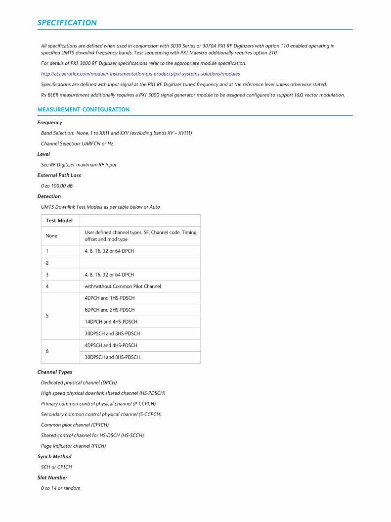
The range is determined by the RF Digitizer noise floor in 3.84 MHz bandwidth, the maximum RF input level and the signal type.
Nominal measured data for 3070A in Band V
Accuracy
See RF Digitizer level accuracy specification
+23°C ±5°C, ±-0.7 dB (2 sigma) for input -20 dBr to 0 dBr W.R.T reference level
FREQUENCY ERROR
Result
Hz
Result output for a random or specified single slot
Range
±6.5 kHz, SNR >20 dB
Accuracy
As per reference standard ±10 Hz
Reference Level(dBm)
Noise Floor (dBm) in 3.84MHz
low noise mode
Noise Floor(dBm) in 3.84
MHzlow distortion
mode
PowerMeasurement
Range (dB)
30 -39, -48 rrc filtered -35 78
0 -66, -74 rrc filtered -61 74
-30 -85, -94 rrc filtered -85 64
OCCUPIED BANDWIDTH
Result
99% Occupied Bandwidth (Hz)
Range
10 MHz span
Input >-40 dBm
Accuracy
<100 kHz with RF input above -40 dBm (SNR >25 dB)
SPECTRAL EMISSIONS
Measured against 3GPP Spectral Emission Limits defined in tables 6.18-6.21 and Additional Band Specific Spectral Emissions for bands II, IV, V,X, XII, XIII, XIV and XXV as defined in table 6.21A-C and for Home BS the Additional Requirements defined in table 6.21 D-E.
Result
Global Pass/Fail, peak level (dB/NBW) and it’s associated frequency (Hz) relative to the selected mask
Segment Pass/Fail, peak level(dB/NBW) and it’s associated frequency (Hz) relative to the selected mask
Mask reference trace and spectrum trace peak dB/NBW versus frequency
Range
Measured across the downlink frequency range for the band selected
Dynamic range >65 dB for Input >-16 dBm
Accuracy
±0.6 dB (2 Sigma)
ACLR (ADJACENT CHANNEL LEAKAGE RATIO)
Result
Reference channel power (dBm/3.84 MHz) through RRC filter with Alpha 0.22
Absolute (dBm) or relative (dBc) upper/lower adjacent and alternate upper/lower channel offset powers (dB/3.84 MHz)
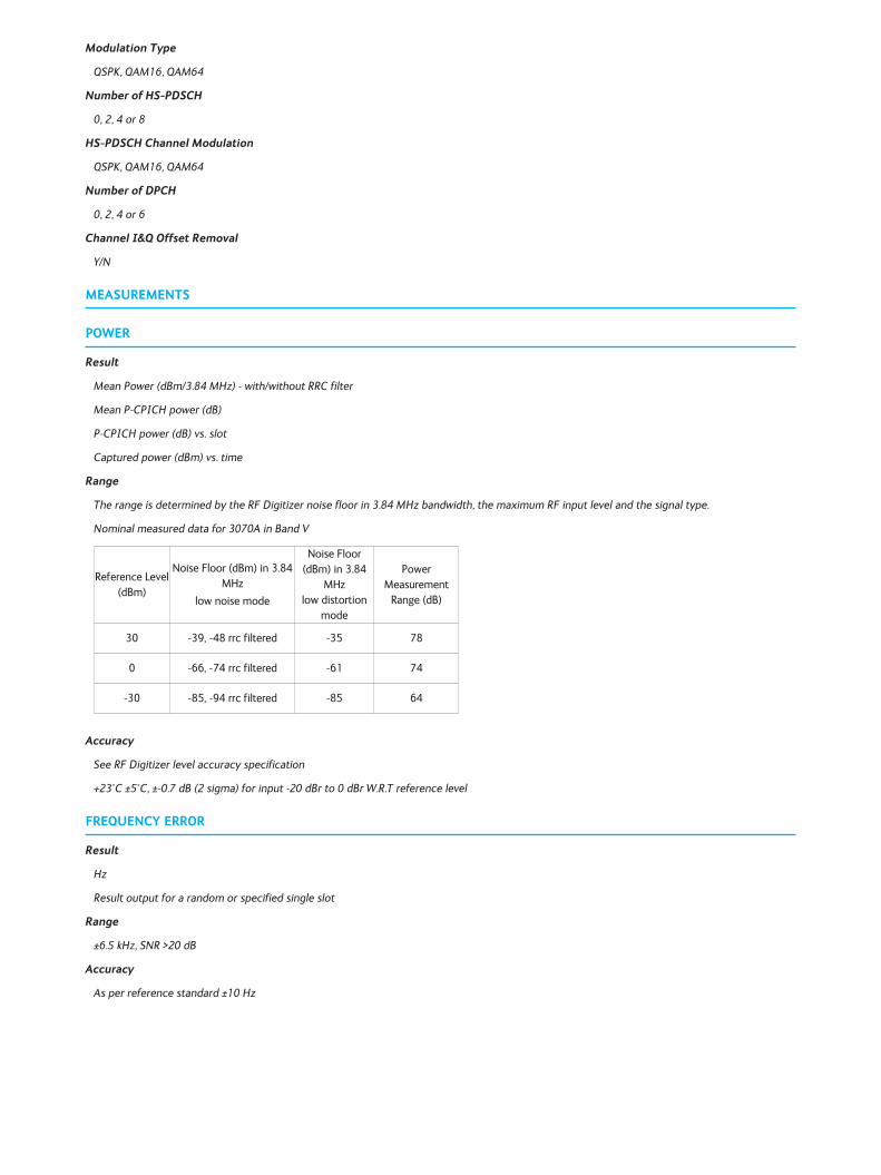
Dynamic Range
TM1 64 DPCH input level >-15 dBm
303xC/3036 Better than 60 dB
3070A Better than 65 dB
Fig 5. 3070A TM1 64 DPCH at 900 MHz
Accuracy
Accuracy ±0.5 dB (2 Sigma) for ACLR >-50 dBc
ERROR VECTOR MAGNITUDE (EVM)
Modulation accuracy results are output for a specified slot 0 to 14 or a randomly selected slot and as either a composite measurement or ameasured value for each channel
Results
EVM rms (%) peak/rms*
Phase Error rms (degrees)* peak/rms
Magnitude Error rms (%) * peak/rms
Mean Frequency Error (Hz)*
Mean PCDE (peak code domain error) (dB)*
IQ Origin offset (dB)
IQ Skew (degrees)
IQ Gain Imbalance (dB)
Clock Error (ppm)
* Trace display is available plotted versus slot number 0-14
Measured and Ideal Channel and Composite Constellations for the composite signal and for each logical channel type
Peak results are tagged with chip position
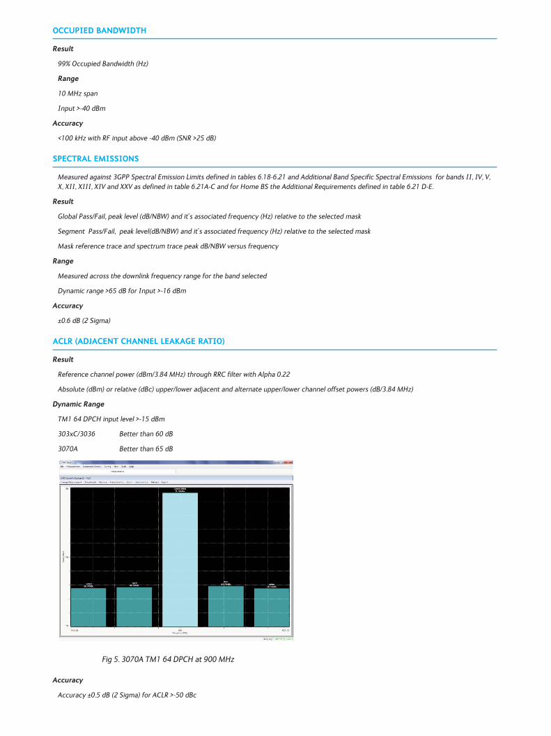
Range
RF input >-20 dB relative to reference level or –16 dBm whichever is the greater
0 to 25%
Accuracy
<1% for EVM of 10%, typically 0.5 %
Residual error <1%
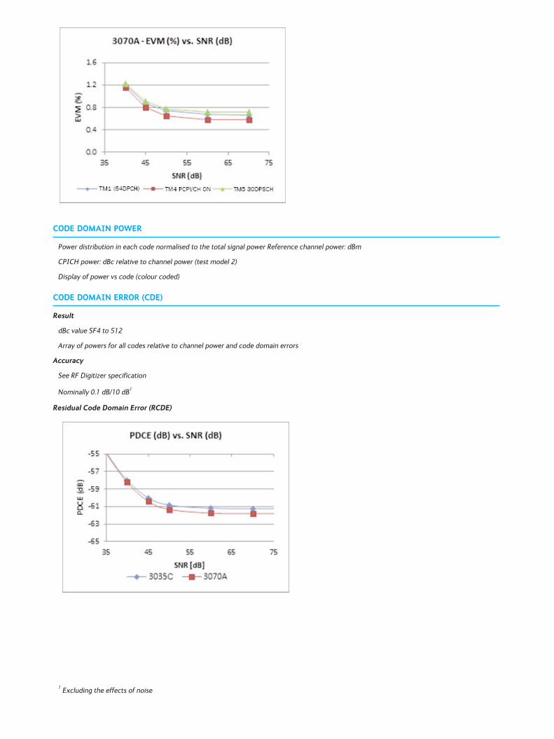
CODE DOMAIN POWER
Power distribution in each code normalised to the total signal power Reference channel power: dBm
CPICH power: dBc relative to channel power (test model 2)
Display of power vs code (colour coded)
CODE DOMAIN ERROR (CDE)
Result
dBc value SF4 to 512
Array of powers for all codes relative to channel power and code domain errors
Accuracy
See RF Digitizer specification
Nominally 0.1 dB/10 dB1
Residual Code Domain Error (RCDE)
1 Excluding the effects of noise
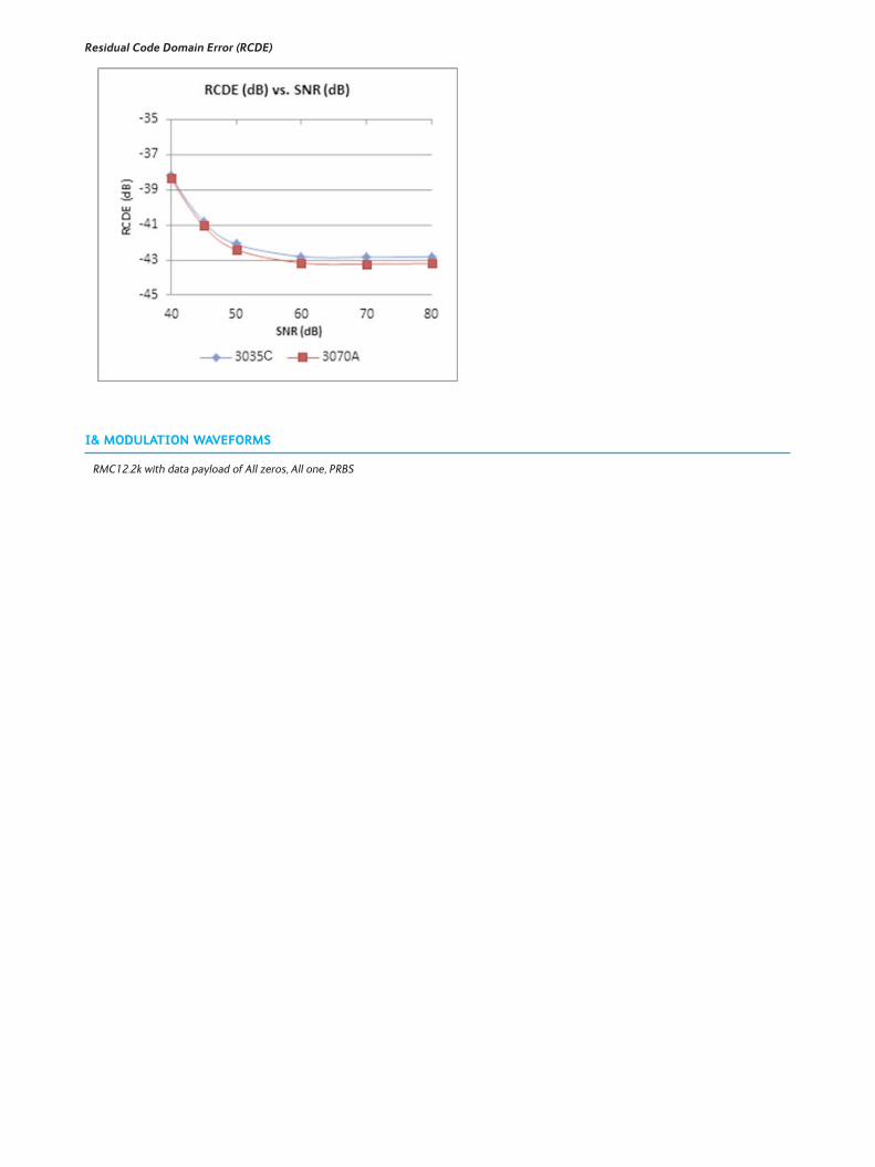
Residual Code Domain Error (RCDE)
I& MODULATION WAVEFORMS
RMC12.2k with data payload of All zeros, All one, PRBS
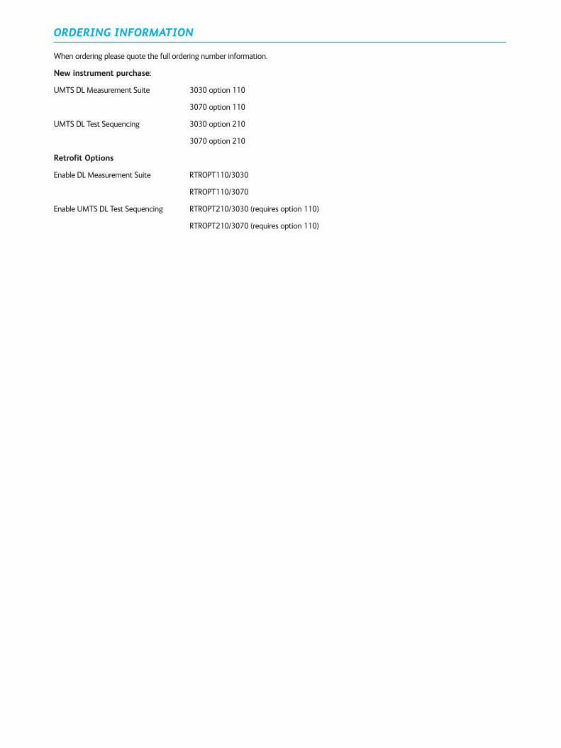
ORDERING INFORMATION
When ordering please quote the full ordering number information.
New instrument purchase:
UMTS DL Measurement Suite 3030 option 110
3070 option 110
UMTS DL Test Sequencing 3030 option 210
3070 option 210
Retrofit Options
Enable DL Measurement Suite RTROPT110/3030
RTROPT110/3070
Enable UMTS DL Test Sequencing RTROPT210/3030 (requires option 110)
RTROPT210/3070 (requires option 110)

Cobham Wireless Longacres House, Six Hills Way, Stevenage, Hertfordshire, SG1 2AN, EnglandT: +44 (0)1438 772200E: [email protected] www.cobham.com/wireless
Part No. 46900/052, Issue 3, 02/15