Embed Size (px)
Citation preview
UML Packages & Related Diagrams
Extending UML Component Deployment
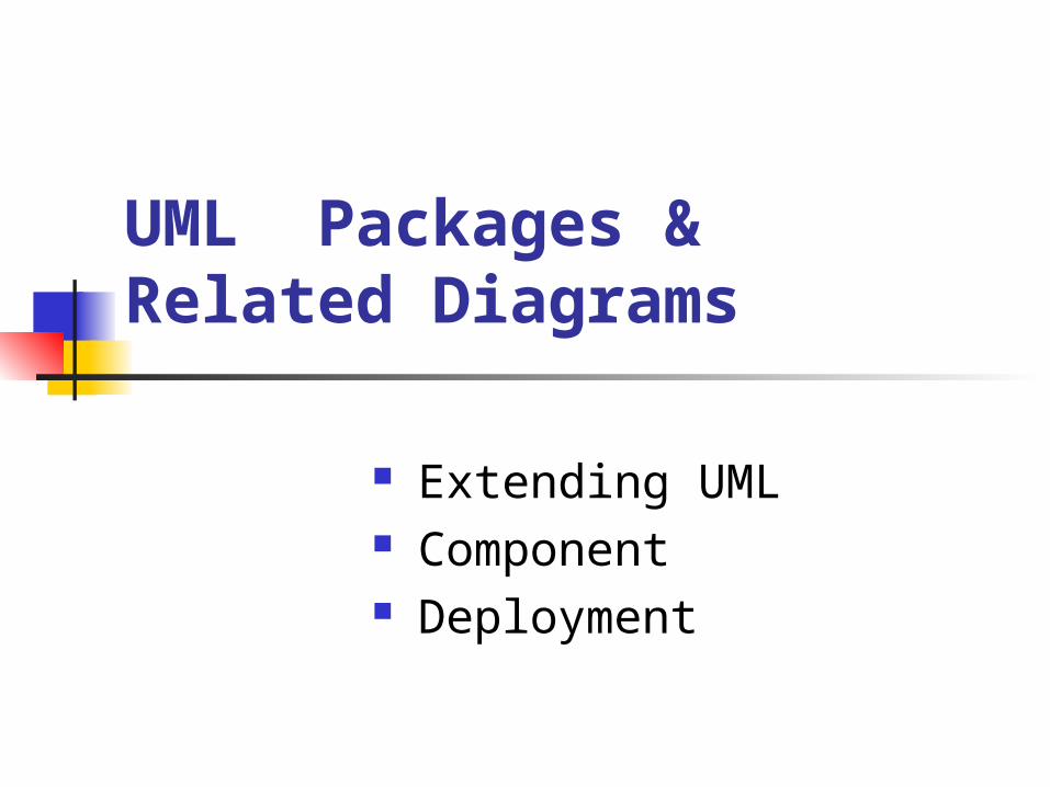
Why extend UML? Although UML is very well-defined, there are situations in which it needs to be customized to specific problem domains
UML extension mechanisms are used to extend UML by:
- adding new model elements, - creating new properties, - and specifying new semantics
There are three extension mechanisms:- stereotypes, tagged values, constraints and notes
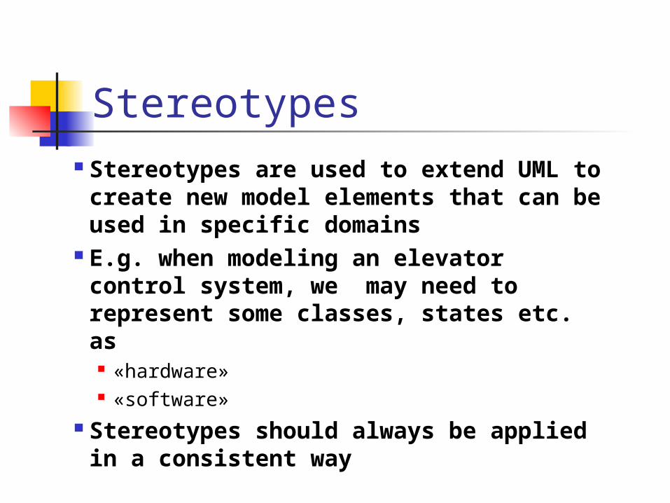
Stereotypes Stereotypes are used to extend UML to create new model elements that can be used in specific domains
E.g. when modeling an elevator control system, we may need to represent some classes, states etc. as
«hardware» «software»
Stereotypes should always be applied in a consistent way
Stereotypes (cont.)
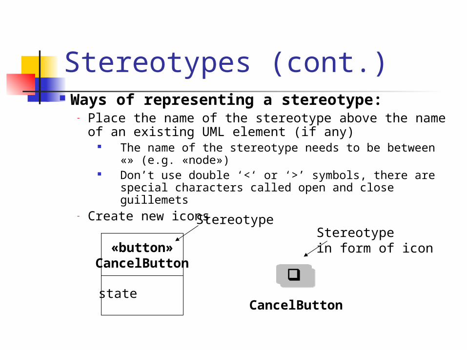
«button»CancelButton
Stereotype
state
Ways of representing a stereotype: - Place the name of the stereotype above the name of
an existing UML element (if any) The name of the stereotype needs to be between «»
(e.g. «node») Don’t use double ‘<‘ or ‘>’ symbols, there are special
characters called open and close guillemets- Create new icons
CancelButton
Stereotypein form of icon
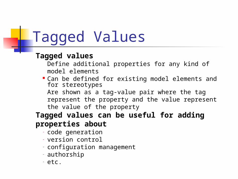
Tagged Values Tagged values
Define additional properties for any kind of model elements
Can be defined for existing model elements and for stereotypes
Are shown as a tag-value pair where the tag represent the property and the value represent the value of the property
Tagged values can be useful for adding properties about
- code generation- version control- configuration management- authorship- etc.
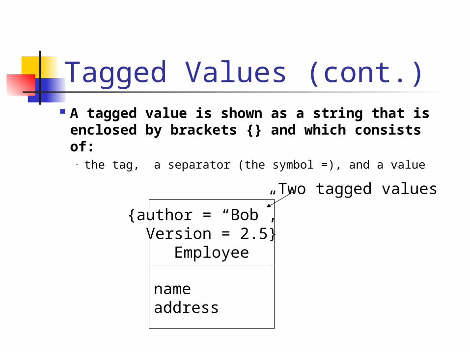
Tagged Values (cont.) A tagged value is shown as a string that
is enclosed by brackets {} and which consists of:
- the tag, a separator (the symbol =), and a value
{author = “Bob”, Version = 2.5}
Employee
nameaddress
Two tagged values
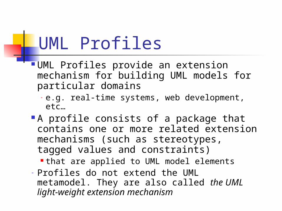
UML Profiles UML Profiles provide an extension
mechanism for building UML models for particular domains
- e.g. real-time systems, web development, etc…
A profile consists of a package that contains one or more related extension mechanisms (such as stereotypes, tagged values and constraints) that are applied to UML model elements
- Profiles do not extend the UML metamodel. They are also called the UML light-weight extension mechanism
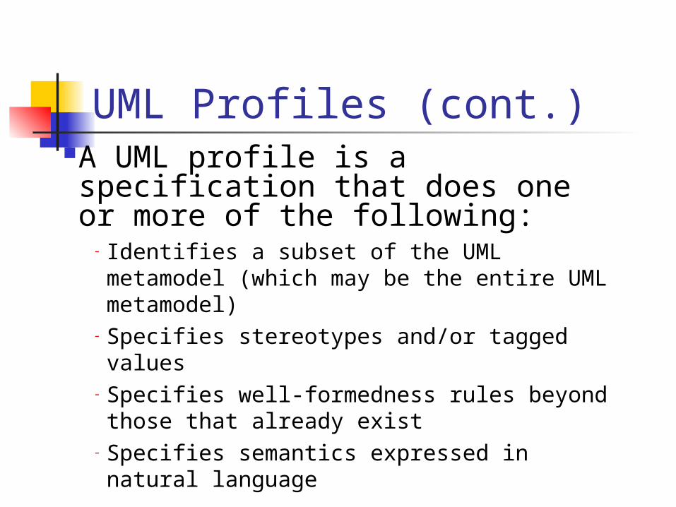
UML Profiles (cont.)A UML profile is a specification that does one or more of the following:
- Identifies a subset of the UML metamodel (which may be the entire UML metamodel)
- Specifies stereotypes and/or tagged values
- Specifies well-formedness rules beyond those that already exist
- Specifies semantics expressed in natural language

Example of a profile inspired by the research report of Cabot et al. (2003)
We would like to create a UML profile for representing basic GUI components.
We suppose that our GUI contains the following components:
- Forms (which can also be dialog boxes)- Buttons
Constraints: (in practice, we need to be more precise)
A form can invoke a dialog box A form as well as a dialog box can contain
buttons
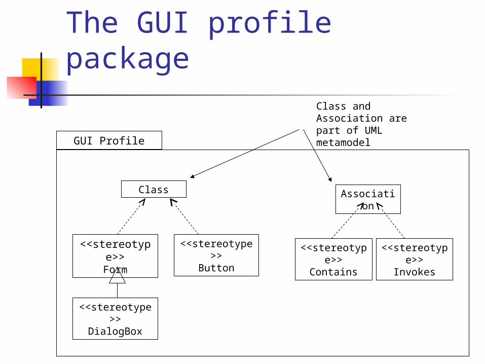
The GUI profile package
GUI Profile
Class
<<stereotype>>Form
<<stereotype>>Button
Association
<<stereotype>>Contains
<<stereotype>>DialogBox
Class and Association are part of UML metamodel
<<stereotype>>Invokes
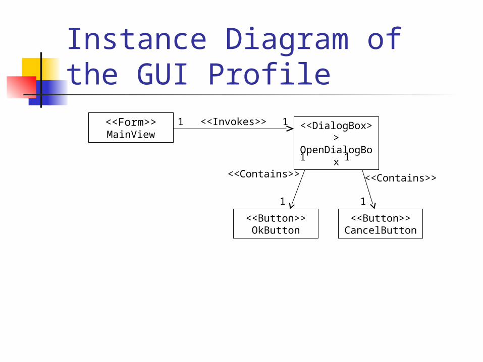
Instance Diagram of the GUI Profile
<<Form>>MainView
1 1
<<Button>>OkButton
<<Button>>CancelButton
<<Invokes>>
<<Contains>> <<Contains>>
<<DialogBox>>OpenDialogBox
1 1
1 1
Drawing Subsystems in UML
System design must model static and dynamic structures: Component Diagrams for static structures
show the structure at design time or compilation time
Deployment Diagram for dynamic structures
show the structure of the run-time system
Component
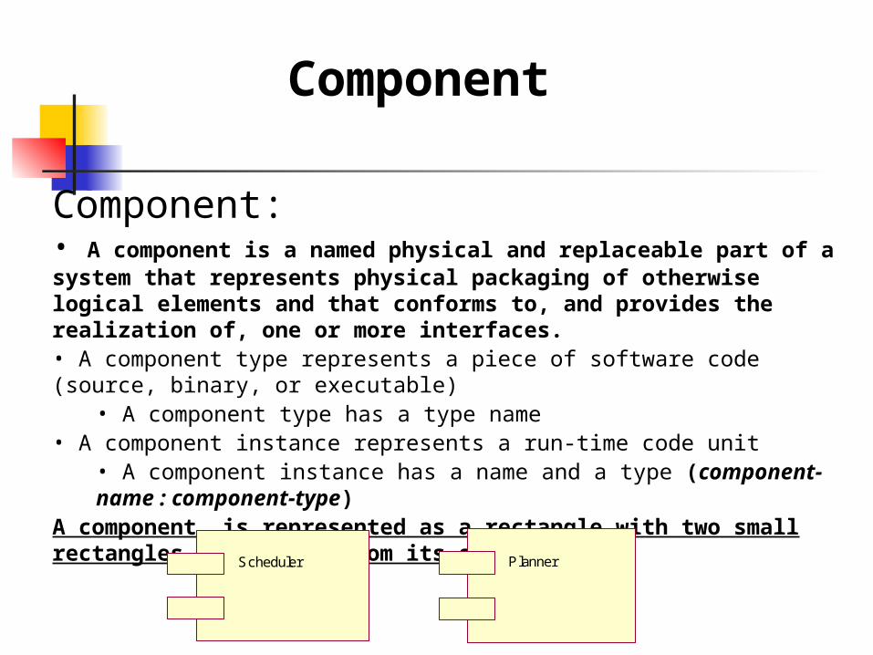
Component:• A component is a named physical and replaceable part of a system that represents physical packaging of otherwise logical elements and that conforms to, and provides the realization of, one or more interfaces.• A component type represents a piece of software code (source, binary, or executable)
• A component type has a type name• A component instance represents a run-time code unit
• A component instance has a name and a type (component-name : component-type)
A component is represented as a rectangle with two small rectangles protruding from its side
PlannerScheduler
Component
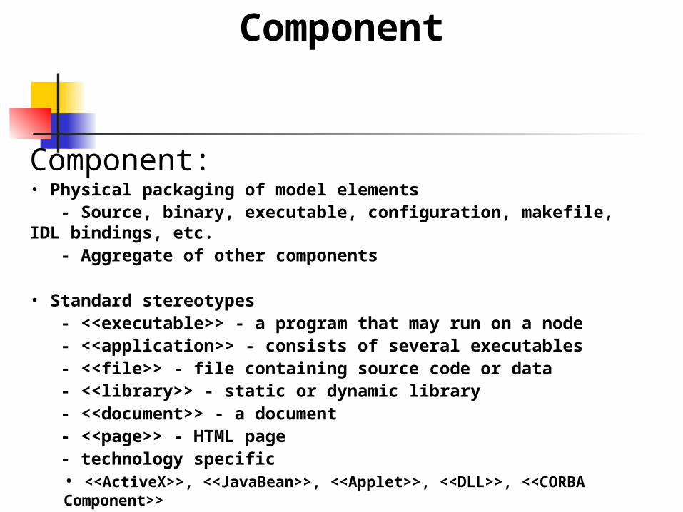
Component:• Physical packaging of model elements - Source, binary, executable, configuration, makefile, IDL bindings, etc. - Aggregate of other components
• Standard stereotypes - <<executable>> - a program that may run on a node - <<application>> - consists of several executables - <<file>> - file containing source code or data - <<library>> - static or dynamic library - <<document>> - a document - <<page>> - HTML page - technology specific
• <<ActiveX>>, <<JavaBean>>, <<Applet>>, <<DLL>>, <<CORBA Component>>
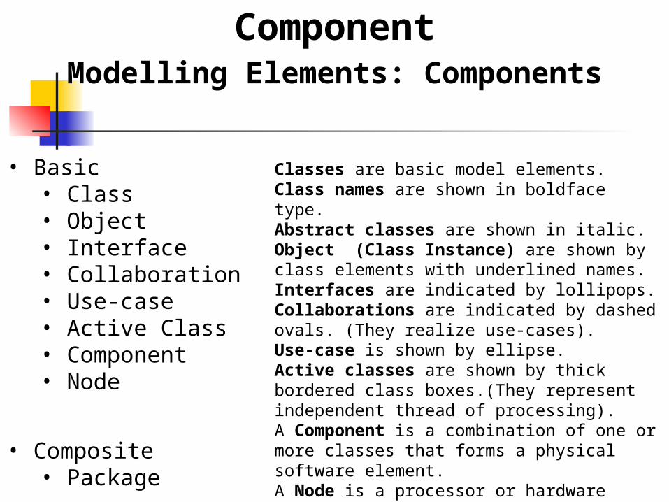
ComponentModelling Elements: Components
• Basic• Class• Object• Interface• Collaboration• Use-case• Active Class• Component• Node
• Composite• Package
Classes are basic model elements.Class names are shown in boldface type.Abstract classes are shown in italic.Object (Class Instance) are shown by class elements with underlined names.Interfaces are indicated by lollipops.Collaborations are indicated by dashed ovals. (They realize use-cases).Use-case is shown by ellipse.Active classes are shown by thick bordered class boxes.(They represent independent thread of processing).A Component is a combination of one or more classes that forms a physical software element.A Node is a processor or hardware device.A Composite Model element is a package or a subsystem of base or composite elements.
Component Diagram Component Diagram
A graph of components connected by dependency relationships.
Shows the dependencies among software components
source code, linkable libraries, executables has only a type form, not an instance form
Dependencies are shown as dashed arrows from the client component to the supplier component. The kinds of dependencies are implementation
language specific.
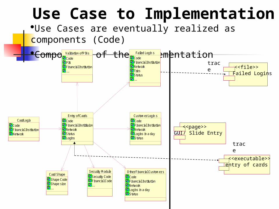
Use Case to ImplementationUse Cases are eventually realized as components (Code)
Components of the Implementation
trace
trace
CardLogin
CodeFinancial InstitutionNetwork
Failed Login s
CodeFinancial InstitutionNetworkTriesStatus...
Customer Login s
CodeFinancial InstitutionNetworkLogins in a dayStatus
Other Financial Customer s
CodeFinancial InstitutionNetworkLogins in a dayStatus
Validation of PINs
CodePINFinancial Institution...
Security Module
Security CodeFinancial Code...
Entry of Cards
CodeFinancial InstitituionNetworkStatusLogins
Card Shape
Shape CodeShape size...
entry of cards<<executable>>
Failed Logins<<file>>
GUI/ Slide Entry<<page>>
Component DiagramComponent Characteristics
• Components trace to the model elements they implement (hence all the way back to use cases)
• A Component usually implements several elements
• Components provide the same interface as the model elements they implement
• Compilation dependencies denote which elements are required to compile a specific component
• Implement component stubs to ease compilation, integration and test
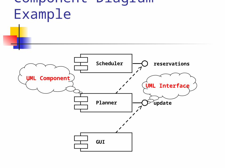
Component Diagram Example
UML InterfaceUML Component
Scheduler
Planner
GUI
reservations
update
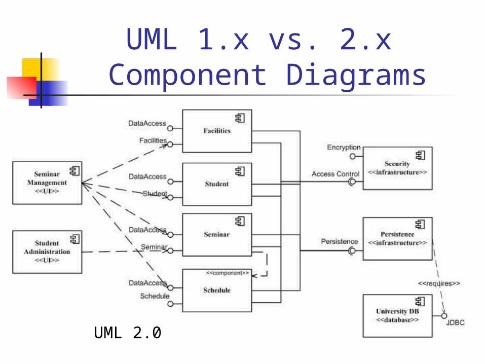
UML 1.x vs. 2.x Component Diagrams
UML 2.0
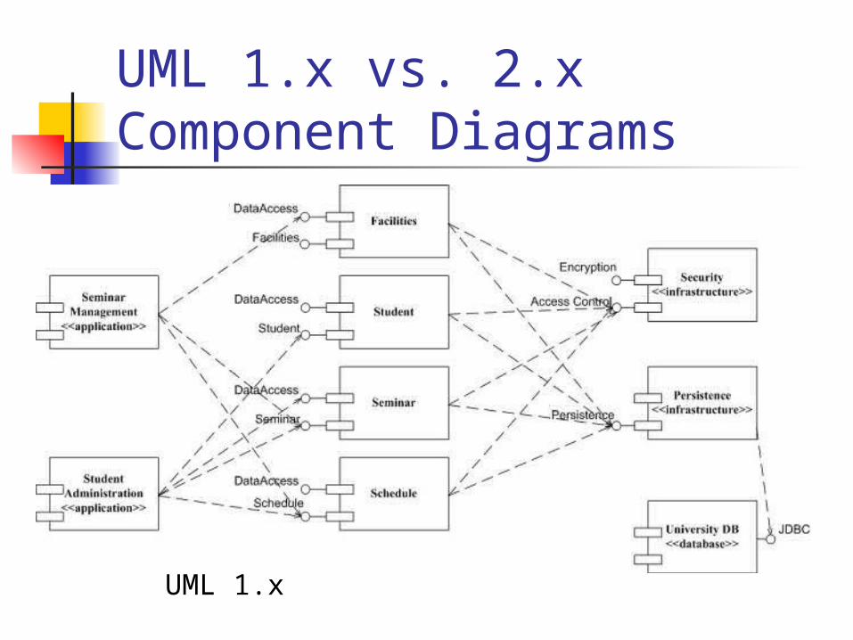
UML 1.x vs. 2.x Component Diagrams
UML 1.x
UML 1.x vs. 2.x Component Diagrams
Notational differences: • UML 2 components are modeled as simple rectangles
•uses this symbol as a visual stereotype within the rectangle
• UML 1.x there were depicted as rectangles with two smaller rectangles jutting out from the left-hand side. As you can see • Both diagrams model dependencies, either between components or between components and interfaces.
•both diagrams use the lollipop symbol to indicate an implemented interface
•the UML 2 version introduces the socket symbol to indicate a required interface.
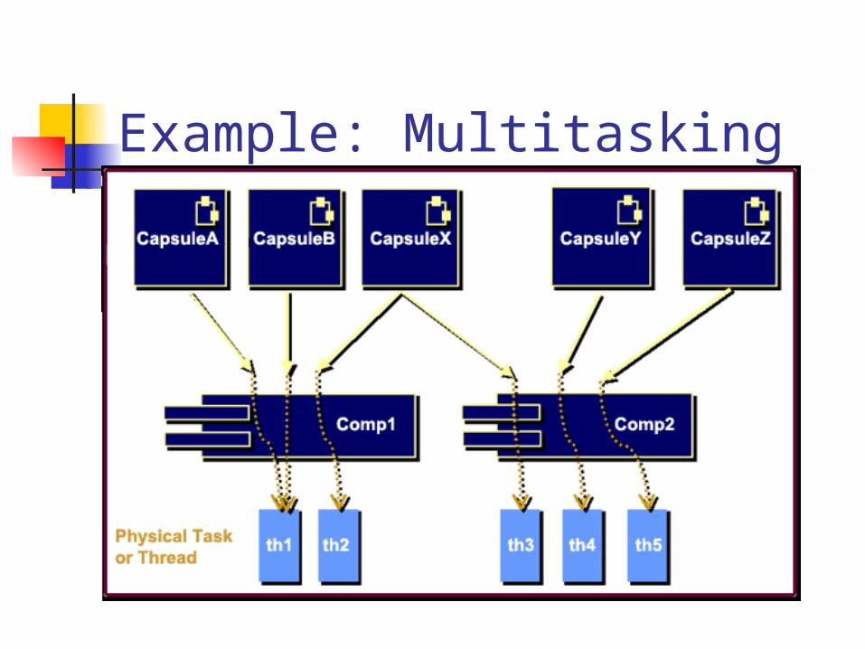
Example: Multitasking
Each capsule (i.e., active class) has its own independent thread of control that is implemented using its state diagram.
can be mapped to a specific component (or set of components), which can then be built as an executable library or external library.
Each component implements a non-trivial set of functionality
may not necessarily be a single unit of code or a single binary.
System architects can use both capsules and components to depict units of distribution, assembly, and deployment.
Example: Multitasking
Deployment Diagram
Deployment diagrams show the configuration of run-time processing elements and the software components, processes, and objects that live on them. Software
component instances represent run-time manifestation of code units.
Components that do not exist as run-time entities do not appear in Deployment diagrams.
Deployment Diagram Deployment diagrams are useful for showing a
system design after the following decisions are made
Subsystem decomposition Concurrency Hardware/Software Mapping
A deployment diagram is a graph of nodes connected by communication associations.
Nodes are shown as 3-D boxes. Nodes may contain component instances. Components may contain objects (indicating that the
object is part of the component)
•A deployment diagram is a graph of nodes connected by communication associations. Nodes may contain component instances; indicates “Component” run on nodes.
•Components may contain objects; indicates “Objects” is part of the component.
•Components are connected to other components by dashed-arrow dependencies.
Deployment Diagram
A Deployment Diagram shows the actual Hardware configuration consisting of
• Nodes (processors)
• Software - Components
• Processes
• Objects
Deployment Diagram
Deployment Diagram
Text
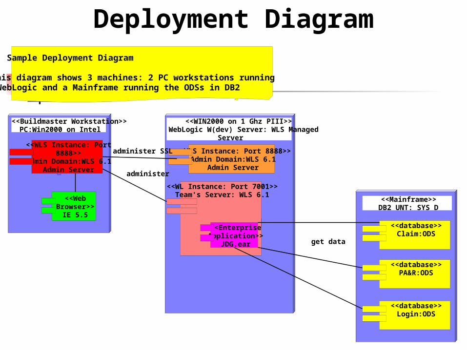
Sample Deployment Diagram
This diagram shows 3 machines: 2 PC workstations runningWebLogic and a Mainframe running the ODSs in DB2
<<Buildmaster Workstation>>PC:Win2000 on Intel
<<WLS Instance: Port8888>>
Admin Domain:WLS 6.1Admin Server
<<WebBrowser>>
IE 5.5 Text
<<WIN2000 on 1 Ghz PIII>>WebLogic W(dev) Server: WLS Managed
Server
<<WLS Instance: Port 8888>>Admin Domain:WLS 6.1
Admin Server
<<WL Instance: Port 7001>>Team's Server: WLS 6.1
<<EnterpriseApplication>>
JDG.ear
Text
<<Mainframe>>DB2 UNT: SYS D
<<database>>Claim:ODS
<<database>>PA&R:ODS
<<database>>Login:ODS
administer SSL
administer
get data
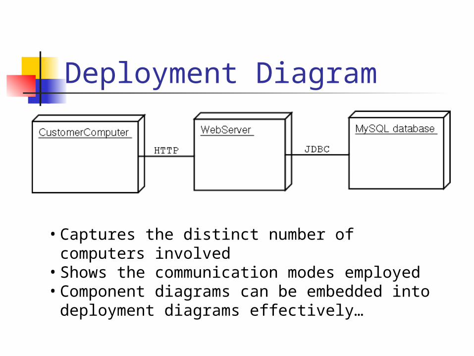
Deployment Diagram
• Captures the distinct number of computers involved• Shows the communication modes employed• Component diagrams can be embedded into deployment
diagrams effectively…
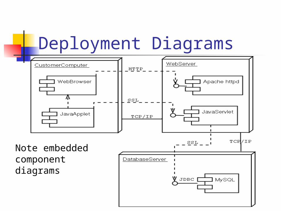
Deployment Diagrams
Note embedded component diagrams
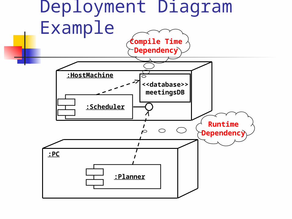
Deployment Diagram Example
RuntimeDependency
Compile TimeDependency
:Planner
:PC
:Scheduler
:HostMachine
<<database>>meetingsDB