Embed Size (px)
Citation preview

VisualAge Smalltalk
UML Designer User’s GuideVersion 5.5
IBM

Note
Before using this document, read the general information under “Notices” on page iii.
August 2000
This edition applies to Version 5.5 of the VisualAge Smalltalk products, and to all subsequent releases andmodifications until otherwise indicated in new editions. Make sure you are using the correct edition for the level ofthe product. The term “VisualAge,” as used in this publication, refers to the VisualAge Smalltalk product set.
Portions of this book describe materials developed by Object Technology International Inc. of Ottawa, Ontario,Canada. Object Technology International Inc. is a subsidiary of the IBM Corporation.
If you have comments about the product or this document, address them to: IBM Corporation, Attn: IBM SmalltalkGroup, 621-107 Hutton Street, Raleigh, NC 27606-1490. You can fax comments to (919) 828-9633.
When you send information to IBM, you grant IBM a nonexclusive right to use or distribute the information in anyway it believes appropriate without incurring any obligation to you.
© Copyright International Business Machines Corporation 1997, 2000. All rights reserved.US Government Users Restricted Rights – Use, duplication or disclosure restricted by GSA ADP Schedule Contractwith IBM Corp.
Notices
References in this publication to IBM products, programs, or services do not implythat IBM intends to make these available in all countries in which IBM operates.Any reference to an IBM product, program, or service is not intended to state orimply that only that IBM product, program, or service may be used. Anyfunctionally equivalent product, program, or service that does not infringe any ofthe intellectual property rights of IBM may be used instead of the IBM product,program, or service. The evaluation and verification of operation in conjunctionwith other products, except those expressly designated by IBM, are theresponsibility of the user.
IBM may have patents or pending patent applications covering subject matter inthis document. The furnishing of this document does not give you any license tothese patents. You can send license inquiries, in writing, to the IBM Director ofLicensing, IBM Corporation, 500 Columbus Avenue, Thornwood, NY, USA 10594.
IBM may change this publication, the product described herein, or both.
TrademarksThe following terms are trademarks of the IBM Corporation in the United States orother countries or both:v VisualAgev UML Designer
The following terms are trademarks of other companies:v Rational (Rational Software Corporation)v Microsoft (Microsoft Corporation)
Windows is a trademark of Microsoft Corporation.
UNIX is a registered trademark in the United States and other countries licensedexclusively through X/Open Company Limited.
© Copyright IBM Corp. 1997, 2000 iii

iv VisualAge Smalltalk: UML Designer User’s Guide
About this document
This document describes how to use the UML Designer feature. UML Designer is atool for capturing and organizing requirements and other high-level designinformation as models, which can then be transformed into implementation usingVisualAge for Smalltalk, or into Java source code (.java files). You can also useUML Designer to analyze and document existing Smalltalk applications.
This document is not intended to document object-oriented analysis and design. Itassumes you are familiar with VisualAge, Smalltalk, OO programming, andUnified Modeling Language (UML) notation. If you are new to UML, see“References” on page vi for some recommended references.
This document is divided into the following sections:v “Part 1. Modeling concepts” on page 1 explains some of the basic concepts
behind modeling with UML Designer. It describes the available model elementsand the various transforms available to generate model elements andimplementation code.
v “Part 2. Using the UML Designer tools” on page 25 gives general informationabout using the UML Designer browsers and diagrammers.
v “Part 3. Building models with UML Designer” on page 65 explains the processof building a model by following a simple example through a “forward” processof requirements, analysis, and design. If you want to get a quick start usingUML Designer, you can read this chapter first, referring to the earlier chapters ifyou want more information.
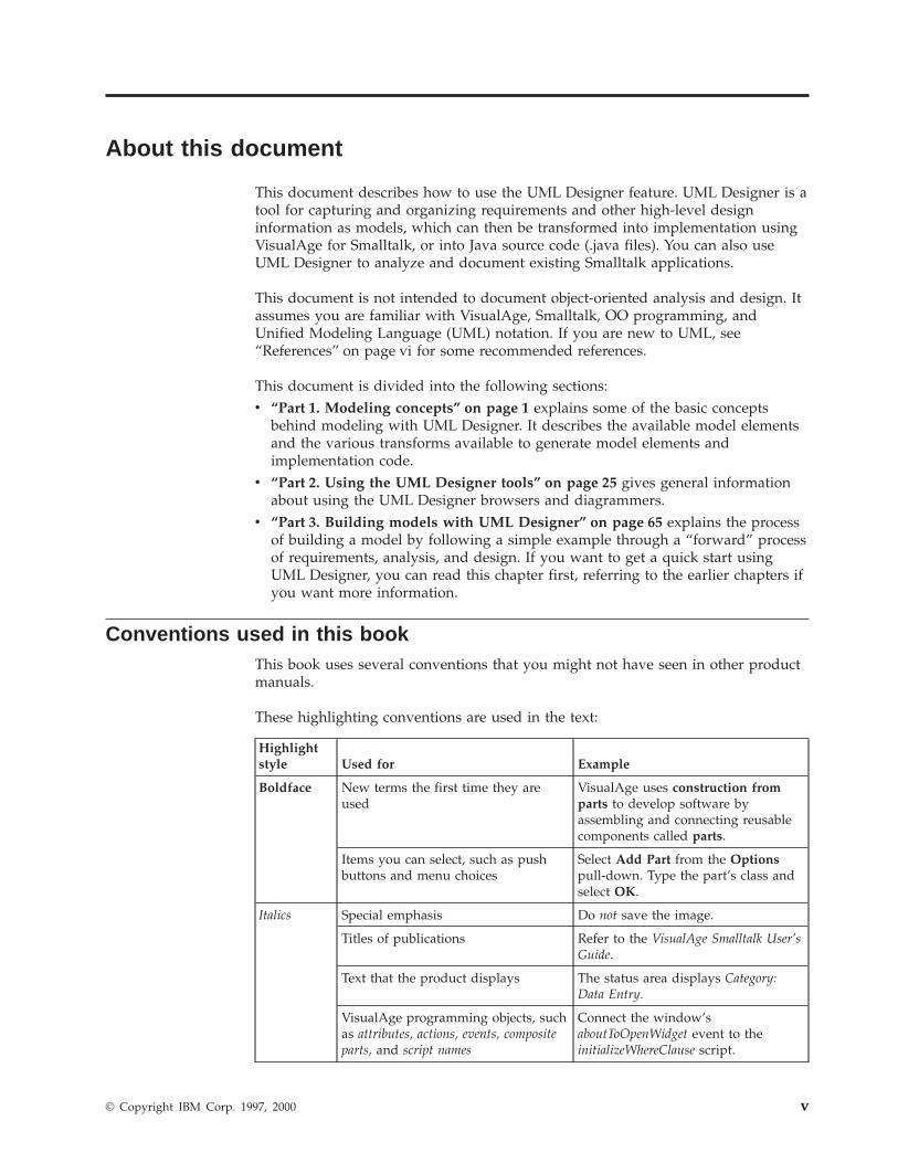
Conventions used in this bookThis book uses several conventions that you might not have seen in other productmanuals.
These highlighting conventions are used in the text:
Highlightstyle Used for Example
Boldface New terms the first time they areused
VisualAge uses construction fromparts to develop software byassembling and connecting reusablecomponents called parts.
Items you can select, such as pushbuttons and menu choices
Select Add Part from the Optionspull-down. Type the part’s class andselect OK.
Italics Special emphasis Do not save the image.
Titles of publications Refer to the VisualAge Smalltalk User’sGuide.
Text that the product displays The status area displays Category:Data Entry.
VisualAge programming objects, suchas attributes, actions, events, compositeparts, and script names
Connect the window’saboutToOpenWidget event to theinitializeWhereClause script.
© Copyright IBM Corp. 1997, 2000 v
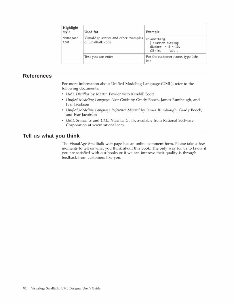
Highlightstyle Used for Example
Monospacefont
VisualAge scripts and other examplesof Smalltalk code
doSomething| aNumber aString |aNumber := 5 * 10.aString := 'abc'.
Text you can enter For the customer name, type JohnDoe
ReferencesFor more information about Unified Modeling Language (UML), refer to thefollowing documents:v UML Distilled by Martin Fowler with Kendall Scottv Unified Modeling Language User Guide by Grady Booch, James Rumbaugh, and
Ivar Jacobsonv Unified Modeling Language Reference Manual by James Rumbaugh, Grady Booch,
and Ivar Jacobsonv UML Semantics and UML Notation Guide, available from Rational Software
Corporation at www.rational.com.
Tell us what you thinkThe VisualAge Smalltalk web page has an online comment form. Please take a fewmoments to tell us what you think about this book. The only way for us to know ifyou are satisfied with our books or if we can improve their quality is throughfeedback from customers like you.
vi VisualAge Smalltalk: UML Designer User’s Guide
Contents
Notices . . . . . . . . . . . . . . . iiiTrademarks . . . . . . . . . . . . . . iii
About this document . . . . . . . . . vConventions used in this book . . . . . . . . vReferences . . . . . . . . . . . . . . . viTell us what you think . . . . . . . . . . . vi
Part 1. Modeling concepts . . . . . . 1
Chapter 1. Introduction to UML Designer 3Features . . . . . . . . . . . . . . . . 3Evolutionary approach . . . . . . . . . . . 4Semantic models . . . . . . . . . . . . . 4
Chapter 2. Model elements . . . . . . . 7Common model elements . . . . . . . . . . 7
Model . . . . . . . . . . . . . . . 7Group . . . . . . . . . . . . . . . 7Stereotype . . . . . . . . . . . . . . 7Diagram . . . . . . . . . . . . . . . 7Publication . . . . . . . . . . . . . . 7
Requirements model elements . . . . . . . . 8Requirement . . . . . . . . . . . . . 8Use case . . . . . . . . . . . . . . . 8Scenario . . . . . . . . . . . . . . . 9Concept . . . . . . . . . . . . . . . 9Actor . . . . . . . . . . . . . . . . 9Thing . . . . . . . . . . . . . . . . 9Responsibility . . . . . . . . . . . . . 9Use case diagram . . . . . . . . . . . . 9
Analysis model elements . . . . . . . . . . 10Protocol . . . . . . . . . . . . . . 10Class diagram . . . . . . . . . . . . 11
Design model elements . . . . . . . . . . 11Class design . . . . . . . . . . . . . 11Instance . . . . . . . . . . . . . . 12Sequence diagram . . . . . . . . . . . 12
Chapter 3. Transforms and codegeneration . . . . . . . . . . . . . 13Going from requirements to analysis . . . . . . 13
Responsibility idioms . . . . . . . . . . 14Java versus Smalltalk conventions . . . . . . 17Finding protocols for participants . . . . . . 17
Going from analysis to design . . . . . . . . 18Message idioms . . . . . . . . . . . . 18
Reverse engineering . . . . . . . . . . . 22Retrieving class designs . . . . . . . . . 22Retrieving protocols . . . . . . . . . . 22Retrieving things . . . . . . . . . . . 23
Part 2. Using the UML Designertools . . . . . . . . . . . . . . . 25
Chapter 4. Using the browsers . . . . 27The Relationships Browser . . . . . . . . . 27
Spawning a new browser . . . . . . . . . 28Browsing groups . . . . . . . . . . . 29Browsing refinement and inheritance . . . . . 29
The Path Browser . . . . . . . . . . . . 30The Hierarchy Browser . . . . . . . . . . 31Filtering . . . . . . . . . . . . . . . 32
Filtering by task . . . . . . . . . . . . 32Filtering by browser level. . . . . . . . . 32
Checking consistency . . . . . . . . . . . 34Browsing inconsistencies . . . . . . . . . 34Repairing inconsistencies . . . . . . . . . 35
System settings . . . . . . . . . . . . . 35
Chapter 5. Using the UML Designerdiagrammers . . . . . . . . . . . . 37Diagrams . . . . . . . . . . . . . . . 37Using the diagrammers . . . . . . . . . . 38
Adding a node figure . . . . . . . . . . 38Adding a connector figure . . . . . . . . 39Direction and ownership of associations . . . . 41Lamination . . . . . . . . . . . . . 41Association labeling . . . . . . . . . . 41Display properties . . . . . . . . . . . 42Alignment . . . . . . . . . . . . . . 43Deleting figures . . . . . . . . . . . . 43Diagram synchronization . . . . . . . . . 44Panning and zooming . . . . . . . . . . 44Creating GIF files . . . . . . . . . . . 45Printing . . . . . . . . . . . . . . 45
Use case diagrammer . . . . . . . . . . . 46Class diagrammer . . . . . . . . . . . . 47
Class figure display properties . . . . . . . 47Connector display options . . . . . . . . 49Relationship properties . . . . . . . . . 49
Sequence diagrammer . . . . . . . . . . . 51Creating instances . . . . . . . . . . . 52Creating method calls . . . . . . . . . . 53
Chapter 6. Configuration managementand version control . . . . . . . . . 55Editions and versions . . . . . . . . . . . 55
Browsing and loading . . . . . . . . . . 55Team development . . . . . . . . . . . 57
Using the UML Designer browsers . . . . . . 57Edition Browser . . . . . . . . . . . . 57Hierarchical Change Browser . . . . . . . 58
© Copyright IBM Corp. 1997, 2000 vii
Chapter 7. Importing and exportingmodels . . . . . . . . . . . . . . . 61Object Extender import/export . . . . . . . . 61
Importing model elements from Object Extender 61Exporting model elements to Object Extender . . 61
XMI import/export . . . . . . . . . . . . 62Exporting from UML Designer to XMI . . . . 63Importing from XMI to UML Designer . . . . 63
Part 3. Building models with UMLDesigner . . . . . . . . . . . . . 65
Chapter 8. Capturing requirements . . 67Starting a new model . . . . . . . . . . . 67Adding Requirement elements . . . . . . . . 68
Chapter 9. Writing and analyzing usecases . . . . . . . . . . . . . . . 69Adding Use Case elements . . . . . . . . . 69Making links between elements. . . . . . . . 69
Adding a ″satisfies″ link . . . . . . . . . 70Analyzing a use case . . . . . . . . . . . 70Identifying actors . . . . . . . . . . . . 71
Adding an Actor element . . . . . . . . . 71Adding a hypertext link . . . . . . . . . . 71Identifying things and responsibilities . . . . . 72
Adding (and linking to) a new Thing element . . 72Identifying responsibilities . . . . . . . . 72Adding responsibility elements . . . . . . . 73Linking to participants . . . . . . . . . 74
Identifying concepts . . . . . . . . . . . 74Adding a Concept element . . . . . . . . 75
Revising description text . . . . . . . . . . 75
Chapter 10. Use case diagrams . . . . 77Creating a use case diagram . . . . . . . . . 77Adding a system figure . . . . . . . . . . 77Adding a use case figure . . . . . . . . . . 78
Adding an actor figure . . . . . . . . . 78Other ways to create relationships . . . . . . 79
Deleting figures . . . . . . . . . . . . . 79
Chapter 11. Protocols . . . . . . . . 81Protocols and things . . . . . . . . . . . 81Generating a protocol . . . . . . . . . . . 81Message specifications . . . . . . . . . . . 82
Generating using idioms . . . . . . . . . . 83Changing parameter and attribute types . . . . . 83
Opening the Path Browser . . . . . . . . 84Changing attribute types . . . . . . . . . 84Changing message parameter types . . . . . 84
Defining a message manually . . . . . . . . 85
Chapter 12. Designing classes andbuilding class diagrams . . . . . . . 87Opening the Class Diagrammer . . . . . . . 87Adding a class design figure . . . . . . . . 87Establishing protocol conformance. . . . . . . 88
Adding a protocol figure . . . . . . . . . 88Generating stub method implementations . . . 89
Adding more elements . . . . . . . . . . 90Creating associations . . . . . . . . . . . 90
A closer look at associations . . . . . . . . 90Adding associations to the diagram . . . . . 91
Showing multiplicity . . . . . . . . . . . 92
Chapter 13. Modeling existing Smalltalkclasses . . . . . . . . . . . . . . 95Attaching a class design to an existing class . . . 95Retrieving a protocol . . . . . . . . . . . 96Retrieving multiple classes at once . . . . . . 97
Chapter 14. Sequence diagrams . . . . 99Creating a sequence diagram . . . . . . . . 99Working with the Sequence Diagrammer . . . . 99
Adding objects to a sequence diagram . . . . 99Adding method calls to the diagram . . . . . 100
Adding the initial method call. . . . . . . 100Adding the remaining method calls . . . . . 101
Chapter 15. Publishing models . . . . 103Publishing automatically . . . . . . . . . 103
Including diagrams in a publication . . . . . 104Publishing manually . . . . . . . . . . . 105
Creating a Publication element . . . . . . 105Editing a Publication element . . . . . . . 105Generating output . . . . . . . . . . . 107
Part 4. Appendixes . . . . . . . . 109
Index . . . . . . . . . . . . . . . 111
viii VisualAge Smalltalk: UML Designer User’s Guide

Part 1. Modeling concepts
© Copyright IBM Corp. 1997, 2000 1

2 VisualAge Smalltalk: UML Designer User’s Guide
Chapter 1. Introduction to UML Designer
UML Designer is a tool for capturing and organizing requirements and otherhigh-level design information as models, which can then be transformed intoimplementation using VisualAge for Smalltalk. You can also use UML Designer toanalyze and document existing Smalltalk applications.
A model is a means of analyzing, representing, and documenting a system. Theimplementation of an object-oriented system can itself be regarded as an executablemodel. But modeling can also help explain a design in terms of higher-levelabstractions (such as requirements and analysis objects) than the implementationcode itself.
UML Designer is tightly integrated with the VisualAge for Smalltalk programmingenvironment, with all models stored in the VisualAge for Smalltalk repository. Thisintegration provides several significant benefits:v Models are treated as software components. The VisualAge for Smalltalk
repository provides configuration management and version control of all designartifacts in the model, including import, export, and reconciliation capabilities.Individual design elements, as well as entire models, can evolve through manyversions, and previous versions can always be retrieved.
v Model elements can be related to their implementations, and implementationscan be explained in terms of higher levels of abstraction. Traceability links makeit possible to navigate between model and implementation entities; they alsomake it possible to propagate changes to the design model to accommodatemodifications discovered during implementation — so-called “round-tripengineering”.
v The transformation from model to implementation is relatively straightforward,and the Smalltalk language makes possible an object-oriented implementation.
UML Designer provides design artifacts and tools that are flexible and can be usedin many different ways. It prescribes no specific OO methodology; it is intended tosupport those elements of OO analysis and design that are common to the majormethodologies and have generally proved most useful to working programmers.UML Designer supports an evolutionary approach to software development, wherethe design undergoes continual revision even after implementation has begun.
FeaturesUML Designer provides capabilities to build models and to present them. With theUML Designer browsers and diagram editors, you can interactively create modelsand can publish them as hardcopy or HTML documents.v Modeling. Distinct design elements are provided for each stage of the modeling
process: requirements capture, analysis, and implementation. Elements areorganized into models representing subsystems, and traceability links make itpossible to maintain connections between design elements and eventualimplementation elements.
v Browsing. Specialized browsers make it possible to organize requirements, usecases, and other OO design artifacts as named design elements. Each elementcan have a natural-language description and hypertext links to other relatedelements.
© Copyright IBM Corp. 1997, 2000 3
v Diagramming. Three graphical editors support the creation of diagrams usingthe Unified Modeling Language (UML) notation. Diagrams are, in effect, tightlyintegrated views of the underlying model, and they automatically reflect changesto design elements.
v Publishing. UML Designer can generate documentation from models and thedesign elements they contain. Supported output formats include HTML and RTF.
Evolutionary approachUML Designer provides tools that support an evolutionary approach to modeling.Traditional modeling techniques have typically assumed a “waterfall”approach—moving forwards from requirements to implementation—but this is notgenerally the preferred approach for OO development, which tends to be iterative.In an OO project, it is equally likely that you will need to start with an existingimplementation or prototype and use modeling to reverse-engineer the analysis fordocumentation purposes.
UML Designer is equally suited to either the “forward” or “backward” approach,or (most typically) a mix of the two.
Semantic modelsUML Designer uses three different semantic models, each representing a differentlevel of abstraction: requirements, analysis, and design. Each model alsocorresponds roughly to a distinct phase in a traditional software developmentprocess, although in reality you will likely move freely between them. Each modelhas its own set of model elements representing artifacts appropriate to that level ofabstraction:
Requirements model
The requirements model provides elements you can use to capture therequirements and boundaries of the system you are designing. Therequirements model focuses on the purposes and use cases for the system,and usually also describes some elements that lie outside the bounds of thesystem.
Requirements and use cases are formulated with the assistance of thesystem’s intended users, and the users must also be able to verify therequirements. Therefore, the analysis in the requirements model isinformal, text-based natural language.
Requirements model elements include requirements, use cases, actors,things, and responsibilities.
Analysis model
The analysis model moves forward from requirements by adding moredetail and providing a rigorous specification of the system’s requiredbehavior.
The analysis centers around protocols, elements that describe behavior interms of abstract interfaces. Protocols are implementation-independent, butthey use a strict type-inheritance model that ensures rigor and internalconsistency. Protocols can be generated from things and responsibilitiesidentified during the requirements phase, generated from existingSmalltalk classes, or created manually.
Analysis model elements include protocols, message specifications,parameters, and return values.
4 VisualAge Smalltalk: UML Designer User’s Guide
Design model
The design model includes elements representing the actual system asimplemented in Smalltalk. You can use these elements to annotate theSmalltalk implementation with traceability information to track how theclasses conform to the protocols defined in the analysis model.
Design model elements include classes, instances, and method calls.
UML Designer includes transforms that can automatically generate model elementsat one level of abstraction based on elements at another. For example, you cangenerate a protocol and its messages based on a thing and its responsibilities.These transforms also include the ability to generate stub implementation code ineither Smalltalk or Java.
You can also create links between model elements at different levels of abstractionto trace how they evolve. These traceability links make it possible to track howyour implementation conforms to your design decisions, and how your designsatisfies your requirements.
Chapter 1. Introduction to UML Designer 5

6 VisualAge Smalltalk: UML Designer User’s Guide
Chapter 2. Model elements
This chapter describes the model elements supported under each of the UMLDesigner semantic models. These elements and their relationships to one anotherare defined in the UML Designer metamodel, which can itself be represented usingmodel elements and diagrams.
Common model elements
ModelA model is a collection of related design elements; these elements can includerequirements, use cases, objects, diagrams, and other artifacts of design. In theVisualAge team library, a model is stored within the context of a Smalltalkapplication.
All of the modeling work connected with designing a system is within the contextof a model, or a set of related models; a model can have another model as aprerequisite. Model elements in a prerequisite model are visible, meaning they canbe accessed (and linked to) from the model specifying the prerequisite. Models canhave “uses” and “used by” relationships to other models.
GroupA group is an element you can use to collect related model elements together.Groups do not correspond to any implementation; they are simply a convenientmeans of organizing model elements according to arbitrary criteria. Groups areuseful for filtering the elements displayed in a browser or included in apublication.
A group is also used as the underlying model element representing the systemboundary in a use case diagram.
StereotypeA stereotype is a UML-defined element you can use to classify an element asbelonging to a user-defined subclass of an existing element. Stereotypes are usefulfor indicating usage distinctions between elements of the same type, but withdifferent intent. Stereotypes are generally important for tools and code generation.
DiagramA diagram is a graphical view of a model, exposing elements that conveyimportant information about a design. A diagram exists independently of anydiagrams it contains, but any changes to the underlying model are automaticallyreflected in affected diagrams.
PublicationA publication is a model element used to generate formatted output from a model(or some subset of a model) suitable for printing or online viewing. You can createpublication elements either automatically or manually. A publication, in effect,describes a textual view of a set of model elements.
© Copyright IBM Corp. 1997, 2000 7
A publication element contains one or more topic elements, each of which cancontain other topics. Each topic contains a text element derived from the textualcontents of a model element. The text of a topic can contain hypertext links to thetext of other topics.
For more information about publishing, see “Chapter 15. Publishing models” onpage 103.
Requirements model elements
RequirementA requirement describes a function the system must perform in order to meet itsfundamental business objectives. Requirements also help to define the boundariesof the system; some functions, though important, might turn out to be outside thescope of the system being developed. Requirements are formulated by the users ofthe system and describe what the system must do.
There are no strict rules governing what you can include as a requirement, norwhat level of detail is appropriate. Indeed, the list is very likely to change overtime, as you gain a better understanding of the problem domain and the systemboundaries. You can use Requirement elements to capture any information that isuseful for setting the system’s objectives and that you want to capture fordocumentation and tracking purposes. Ideally, requirements should be short,succinct, and focused on the essential purpose of the system. Often, therequirement’s title alone will suffice; other times, you might want to providefurther explanation, which you can enter as hypertext.
A requirement should avoid any unnecessary descriptions of how the system willbe implemented; instead, it should describe what the system must do for the userin order to work successfully. If you have quantifiable requirements that must bemet, such as response times or scalability objectives, you can include these as well.
Use caseA use case is a specific case of usage, tracing a particular task through from startto finish. Rather than concentrating on how the system functions, use cases describewhat the system must do from the user’s perspective. A use case begins with somestimulus from someone or something outside the system (an actor, which we willdiscuss in more detail shortly).
Though more detailed than requirements, use cases are still quite informal. A usecase should be a natural-language description, not pseudocode, and it shouldavoid any unnecessary assumptions about implementation. A use case should dothe following:v It should help to capture the purpose of the system from the user’s perspective.v It should define the system boundaries by identifying external agents (actors).
The style and level of detail to use in writing use cases are matters of judgmentand experience. The amount of detail you should include depends upon thenovelty of the system and your familiarity with the problem domain. The level ofdetail can also vary from one use case to another: some might describe high-levelinteractions of real-world elements, while others might describe low-levelinteractions of actual system objects (when such objects are known). But try toavoid mixing levels of abstraction within a single use case.
8 VisualAge Smalltalk: UML Designer User’s Guide
Above all, remember that use cases are not formal; they are written in naturallanguage rather than adhering to any rigorous, readily programmable semantics.This can lead to some imprecision or ambiguity, but it has the advantage ofmaking the requirements readily understandable to, and verifiable by, the users ofthe system.
ScenarioA scenario is an instance of a use case. In other words, a scenario traces aparticular execution of a use case from start to finish, with specific conditions andvalues. While a use case might encompass several possible outcomes dependingupon conditions, a scenario describes only one outcome. Consequently, there mightbe multiple scenarios associated with a single use case.
ConceptA concept is any significant term or idea that is doesn’t necessarily qualify as anactor or a thing. This category can include any aspect of the system you want tocapture, such as real-world objects outside the system or domain-specificterminology. You might later decide that the idea described by a concept is also anactor or a thing, in which case you can create links to indicate this relationship.
ActorAn actor is an entity outside the system that provides a stimulus setting a use casein motion, or receiving the output from a use case. An actor is not actually part ofthe system, but is some real-world entity that interacts with the system. Usually,actors are human users, although they can also be other software or hardwareentities that initiate actions.
ThingA thing (also called a domain object) is an entity inside the system. Things arecandidates to become objects in the eventual implementation.
A thing can be transformed into a protocol. See “Chapter 3. Transforms and codegeneration” on page 13 for more information.
ResponsibilityA responsibility is a duty of a thing or actor, something it must do in order for ause case to complete successfully. Each thing or actor can have manyresponsibilities, and each can collaborate with other things or actors in theirresponsibilities. A responsibility of a thing is a candidate ultimately to become oneor more methods of an implementation object or a relationship between objects.
A responsibility can be transformed into a message specification. See “Chapter 3.Transforms and code generation” on page 13 for more information.
Use case diagramA use case diagram is a UML-compliant diagram that gives a visual representationof the system being designed, its actors and use cases, and their relationships. Formore information about use case diagrams, see “Use case diagrammer” on page 46.
Chapter 2. Model elements 9
Analysis model elements
ProtocolA protocol is a specified object interface, a named set of message specificationsdefining what messages an object must understand, what their parameters are, andwhat their return values will be. A protocol defines a type rather than a class; itdoes not say anything at all about implementation, only external behavior. Inputparameters and return values are specified in terms of other types, which mustalso be defined by protocols.
A class is said to conform to a protocol if it implements all of the messagesdefined by that protocol and adheres to the specified types for input and outputvalues. A class can conform to more than one protocol, so multiple inheritance oftypes is possible.
In addition, protocols can refine other protocols. (This is similar to, but distinctfrom inheritance among classes, which is implementation-based.) A refining protocolcan add additional message specifications, but it cannot remove any. It can alsorefine the input and output types of the message specifications defined by thesupertype, but only in specific ways:v The input parameter types can be less specific than those defined by the
supertype, accepting anything accepted by the supertype and more.v The return type can be more specific than the one defined by the supertype,
returning only a subset of the possible types returned by the supertype.
A protocol can be generated from a thing, or it can be retrieved from an existingclass. See “Chapter 3. Transforms and code generation” on page 13 for moreinformation.
Message specificationA message specification is an element contained within a protocol. It defines asingle message signature, including parameters and return values. It can alsospecify exceptions.
A message specification can be generated from a responsibility, or it can beretrieved from an implemented method. See “Chapter 3. Transforms and codegeneration” on page 13 for more information.
ParameterA parameter element is part of a message specification. It defines the name andtype of a single message parameter. Type is specified in terms of a definedprotocol. The parameter can also specify aliasing (whether the parameter is thesame as the return value).
Return valueA return value element is part of a message specification. It specifies the name andtype of a message return value. Type is specified in terms of a defined protocol.The return value can also specify aliasing (whether the return value is the same asone of the message parameters).
ExceptionAn exception element is part of a message specification. It specifies a named errorcondition that a message can raise. Identifying possible error conditions helps toensure that they are handled.
10 VisualAge Smalltalk: UML Designer User’s Guide
Class diagramA class diagram is a UML-compliant diagram that shows the relationships betweenclasses, instances, and protocols in your model. For more information about classdiagrams, see “Class diagrammer” on page 47.
Design model elements
Class designA class design is a model element that represents a class. A class design can be(but does not have to be) connected to a real Smalltalk class. The class design,rather than a real Smalltalk class, can then be connected to other model elements.In a class diagram, each class figure is attached to a class design rather than to anactual class.
Class designs provide an indirect coupling between your model and the actualSmalltalk implementation. During design, you might not yet be ready to startcreating actual Smalltalk classes; instead, you can create class designs (which arecomparatively lightweight) without any underlying Smalltalk classes. (However,you must create a real Smalltalk class if you want to create inheritancerelationships between class designs.)
Furthermore, you might not yet know what your actual classes will be named, oryou might want to use names other than the ones your actual classes will have(this might be the case if you are documenting legacy classes). A class design canhave a different name from that of the Smalltalk class it is associated with; even ifthe names are different, a class design will still reflect any changes made to theunderlying class.
Class designs also serve as a repository for class-related design information that isnot normally captured in a Smalltalk code. For example, a class design can have aconformance link to one or more protocols, indicating that the attached classshould implement all of the methods defined by the protocols. By conforming toprotocols, class designs also specify information such as parameter and returntypes, which otherwise are not specified by a Smalltalk class definition. (On theother hand, class designs do not duplicate any information stored in the class itself,such as its methods or instance variables.)
In effect, class designs provide a bridge between analysis elements (like protocols)and implementation classes. They provide traceability links from implementationclasses back to the model elements from which they are derived.
A class design combines the interface of its Smalltalk class with those of anyprotocols to which it conforms. Its methods, therefore, fall into two categories:v Methods defined in a protocol to which the class design conforms. These are
called specified methods. A specified method might or might not actually beimplemented in the underlying class, if any.
v Methods defined in the underlying Smalltalk class the class design is linked to,if any. These are called implemented methods. An implemented method mightor might not be specified by any protocols the class design conforms to.
Similarly, the attributes of a class design can be either specified or implemented (orboth).
Chapter 2. Model elements 11
A class design can be retrieved from an existing class. See “Chapter 3. Transformsand code generation” on page 13 for more information.
InstanceAn instance element represents a named instance of a class design, from which itinherits its attributes. Essentially, an instance represents a sample object with stateinformation and specific values for its attributes. Instances are useful for buildingexamples and sequence diagrams.
Sequence diagramA sequence diagram is a visual representation of a series of interactions betweenthe objects in your system. Unlike a class diagram, which is a representation of astatic model of the system, a sequence diagram is a representation of the dynamicinteraction of your system, serialized over time. For more information aboutsequence diagrams, see “Sequence diagrammer” on page 51.
Method callA method call appears within a sequence diagram and represents a message sendfrom one object to another, and the passing of control from the sender to thereceiver.
Method instanceA method instance (or activation) appears within a sequence diagram andrepresents the active execution of a method, beginning with a message send andending with a return.
Method returnA method return appears within a sequence diagram and represents the return ofcontrol from a method that has finished executing.
12 VisualAge Smalltalk: UML Designer User’s Guide
Chapter 3. Transforms and code generation
Each of the three UML Designer semantic models (requirements, analysis, anddesign) represents a different level of abstraction, and each has its own set ofmodel elements. Although these elements represent distinct objects, in many casesthere is a logical correspondence between an element at one level of abstractionand an element at the next level. For example, a Thing element (requirementsmodel) typically corresponds to a Protocol element (analysis model), which in turncorresponds to a class (design and implementation model).
UML Designer provides transform capabilities that can map between modelelements at a different levels of abstraction. Transforming takes the selectedelement, creates its corresponding element or elements, and automatically creates atraceability link between them.
Transforms exist for both the “forward” mapping (requirements → analysis →design) and the “backward” mapping (reverse engineering). “Forward” transformsinclude:v Generating protocols from things (going from requirements to analysis); this
includes generating protocol message specifications, associations, and attributesfrom responsibilities
v Code generation (going from analysis to design and implementation); thisincludes generating classes and methods from class designs and protocols
“Backward” transforms include:v Retrieving protocols from Smalltalk classes and class designs; this includes
retrieving protocol message specifications from Smalltalk class methodsv Creating things from protocols
Going from requirements to analysisThe first phase in a “forward” development process, capturing requirements, yieldselements such as requirements, use cases, things, and actors. Of these, things aremost important from a transform perspective, because things represent domainobjects (and potential implementation classes). By transforming things intoprotocols, you can move from requirements capture to analysis.
The Generate Protocol transform maps things to protocols and responsibilities toprotocol message specifications. The default mapping of things to protocols isone-to-one: transforming a thing into a protocol results in the creation of a Protocolelement that, by default, has the same name as the thing. For example, a thingcalled Car would result in a protocol called <Car>. You can rename the generatedprotocol while still maintaining its traceability link back to the original thing.
The default mapping of a responsibility of a thing depends upon the idiom of theresponsibility; a responsibility and its participants will be mapped, according to itsidiom, into one or more message specifications and parameters. In this way, youcan go from the informality of responsibilities to the relative rigor of messagespecifications.
You can transform responsibilities collectively or one at a time. You can alsomodify the generated message specifications afterward.
© Copyright IBM Corp. 1997, 2000 13
Responsibility idiomsAn idiom specifies a mapping of a responsibility into one of several predefinedimplementations as message specifications. For a given responsibility, you canchoose one of four idioms:
ActionA responsibility to perform an arbitrary action or operation. This is ageneral-purpose, nonspecific idiom that describes something the thing does.
ReferenceA responsibility to keep a value that refers to another thing. This idiomdescribes something the thing knows.
Value A responsibility to keep a value as an attribute. This idiom describessomething the thing keeps.
IdentifierA responsibility to keep a value that can be used to uniquely identify thething. This idiom describes an attribute the thing can be identified by.
For example a Customer thing might have the following responsibilities:
Idiom ResponsibilityAction pay billReference sales repValue account balanceIdentifier customer number
An idiom provides guidance to UML Designer regarding how the responsibilityshould be transformed into protocol message specifications and attributes. For eachidiom, there is a corresponding set of messages that would typically be used toimplement the responsibility. (Essentially, these are simple patterns: designs forimplementing common programming requirements.) Each idiom results in adifferent combination of messages and attributes in the generated protocol, basedon what would typically be used for such a responsibility.
14 VisualAge Smalltalk: UML Designer User’s Guide
ActionAction is the simplest idiom, and describes an arbitrary, user-defined responsibility.It is the default idiom for a new responsibility.
The Action idiom specifies a simple, one-to-one transform from a responsibility toa protocol message specification. For each Action responsibility, UML Designergenerates a single message. The name of the message is the responsibility’simplementation name, which by default is derived from the responsibility name;for example, pay bill becomes payBill. (You can change the implementation name ifyou prefer a different name.)
Participants are optional for an Action responsibility. If there are any participatingthings in a responsibility, each participant becomes a message parameter whosetype is the default type derived from the participant. Message parameters must bespecified as protocols, so if a protocol does not yet exist for a participant, UMLDesigner automatically generates an empty protocol for it.
You can specify a maximum cardinality of Many or 1. If you specify Many, thedefault generated message name will be plural.
Question for Nick: Does cardinality have any other effect on an Actionresponsibility?
No attributes or associations are generated for an Action responsibility.
ReferenceA Reference responsibility specifies a value that the thing knows that is itselfanother thing. In effect, this specifies an association for the implementing protocol.
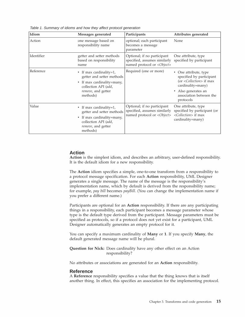
Table 1. Summary of idioms and how they affect protocol generation
Idiom Messages generated Participants Attributes generated
Action one message based onresponsibility name
optional; each participantbecomes a messageparameter
None
Identifier getter and setter methodsbased on responsibilityname
Optional; if no participantspecified, assumes similarlynamed protocol or <Object>
One attribute, typespecified by participant
Reference v If max cardinality=1,getter and setter methods
v If max cardinality=many,collection API (add,remove, and gettermethods)
Required (one or more) v One attribute, typespecified by participant(or <Collection> if maxcardinality=many)
v Also generates anassociation between theprotocols
Value v If max cardinality=1,getter and setter methods
v If max cardinality=many,collection API (add,remove, and gettermethods)
Optional; if no participantspecified, assumes similarlynamed protocol or <Object>
One attribute, typespecified by participant (or<Collection> if maxcardinality=many)
Chapter 3. Transforms and code generation 15
At least one participant is required for a Reference responsibility; the participantidentifies the thing the responsibility refers to. In the generated protocol, UMLDesigner generates an attribute to hold the reference; its type is that of theimplementing protocol for the participating thing. (If you specify more than oneparticipant, any of the specified types are permitted.)
In addition to the attribute, UML Designer generates a set of messages to get andset the attribute’s value. The specific behavior varies depending upon themaximum cardinality you specify (Many or 1):v If you specify a maximum cardinality of 1, the protocol corresponding to the
participant is used as the generated attribute’s type. (If multiple participants arespecified, there is still only one attribute, which can be of any of the specifiedtypes.) In addition, UML Designer generates getter and setter messages for theattribute, using the appropriate protocols as the allowed types for theirparameters and return values.
v If you specify a maximum cardinality of Many (the default), the generatedattribute will be a collection, which can contain multiple items of the allowedtypes. In this case, UML Designer generates a getter method for the collection,along with add and remove messages for the elements in the collection.
In addition, for a Reference responsibility, UML Designer creates an associationbetween the generated protocol and any participating protocols. This is only anassociation between protocols; it does not automatically become an associationbetween classes during the design phase.
ValueA Value responsibility describes a value that the thing knows. In some ways, thisis similar to a Reference, but in this case the thing being pointed to is notnecessarily interesting in its own right.
For each Value responsibility, UML Designer generates a protocol attribute to holdthe value, as well as a set of message specifications to get and set the attribute’svalue.
Specifying a participant is optional for a Value responsibility. If you specify aparticipant, the corresponding protocol is used as the type of the generatedattribute and of the message parameters and return values. If no protocol exists forthe participant, UML Designer automatically generates one.
If you do not specify a participant, UML Designer checks for an existing thing witha similar name to that of the responsibility. If it finds a match, it uses thecorresponding protocol as the type of the attribute. If it does not find a match, itassumes <Object>. (See “Finding protocols for participants” on page 17 for moreinformation.)
In addition to the attribute, UML Designer generates a set of messages to get andset the attribute’s value. The specific behavior varies depending upon themaximum cardinality you specify (Many or 1):v If you specify a maximum cardinality of 1 (the default), the protocol
corresponding to the participant is used as the generated attribute’s type. (Ifmultiple participants are specified, there is still only one attribute, which can beof any of the specified types.) In addition, UML Designer generates getter andsetter messages for the attribute, using the appropriate protocols as the allowedtypes for their parameters and return values.
v If you specify a maximum cardinality of Many, the generated attribute will be acollection, which can contain multiple items of the allowed types. In this case,
16 VisualAge Smalltalk: UML Designer User’s Guide
UML Designer generates a getter method for the collection, along with add andremove messages for the elements in the collection.
No associations are generated for a Value responsibility.
IdentifierAn Identifier responsibility describes a value that the thing knows, and by whichit can be uniquely identified.
For each Identifier responsibility, UML Designer generates a protocol attribute tohold the identifier, as well as getter and setter messages to access the attribute’svalue.
Specifying a participant is optional for an Identifier responsibility. If you specify aparticipant, the corresponding protocol is used as the type of the generatedattribute and of the message parameters and return values. If no protocol exists forthe participant, UML Designer automatically generates one.
If you do not specify a participant, UML Designer checks for an existing thing witha similar name to that of the responsibility. If it finds a match, it uses thecorresponding protocol as the type of the attribute. If it does not find a match, itassumes <Object>. (See “Finding protocols for participants” for more information.)
Note: An identifier is, by definition, of a single specified type; if you specify morethan one participant for an Identifier responsibility, only the first is usedwhen transforming to a protocol.
No associations are generated for an Identifier responsibility.
Java versus Smalltalk conventionsIn the system settings, you can specify that you want to generate Java code insteadof Smalltalk classes. If you select this option, UML Designer uses differentconventions when generating accessor messages from a responsibility.
The differences between the Smalltalk conventions and the Java conventions are asfollows:
Smalltalk conventions Java conventions
v add and remove messages specificationsreturn the added or removed object
v colons are used to indicate keywordparameter positions
v add and remove message specifications donot return the added or removed element
v colons are not used to indicate keywordparameter positions
Finding protocols for participantsWhen you transform a responsibility into a message specification, the types of thegenerated parameters and return values must be specified as protocols. Dependingupon your selections, UML Designer can use several different methods of choosingwhich protocol to use for a parameter or return value.
If a responsibility specifies a participating thing, UML Designer uses theimplementing protocol of the thing as the type for the corresponding messageparameter.
Chapter 3. Transforms and code generation 17
However, participants are optional for responsibilities using the Value or Identifieridioms, even though some of the generated messages take parameters. If you donot specify a participant, UML Designer chooses a default parameter type asfollows:1. If you have specified English link labeling in the system settings, UML
Designer looks for a noun in the responsibility implementation name. Forexample:v name in customerName
v date in dateOfBirth
v indicator in ownerIndicator
If you have not specified English link labeling, UML Designer uses the entireimplementation name. (For more information about the system settings, see“System settings” on page 35.
2. Using the noun or implementation name, UML Designer then looks for a Thingwhose name matches. If it finds one, and the thing has an implementingprotocol, it uses that protocol. For example:v name matches Name, a Thing element in the Kernel model; its implementing
protocol is<String>.v indicator matches Indicator, a Thing element in the Kernel model; its
implementing protocol is <Boolean>.3. If no Thing element matches, UML Designer then looks for a protocol whose
name matches the noun or implementation name. If it finds one, it uses thatprotocol.For example, Date matches the protocol <Date>.
4. If Relationships Browser cannot find a matching thing or protocol, it uses<Object>.
Going from analysis to designThe analysis phase of a “forward” development process yields protocols andmessage specifications. These elements can in turn be used to generateimplementation code.
Although much of the actual implementation of your program logic is still up toyou, some of the structure of objects and methods can often be deduced fromprotocols and their message specifications. When you transform a protocol into aclass design, UML Designer can also generate an actual Smalltalk or Java classwith attributes and stub methods based on the messages of the protocol.Depending on the idioms of the protocol messages, it might also be able togenerate default implementation code for the method.
UML Designer can generate both class and instance methods, although if you aregenerating Java there are some limitations on class attributes. Class methods arespecified by a class conformance relationship between the protocol and theimplementation class; instance methods are specified by an instance conformancerelationship. (You can specify class or instance conformance when you transform aprotocol to a class design.)
Message idiomsAs with the responsibilities of things, protocol message specifications arecharacterized by idioms; however, message idioms are distinct from responsibility
18 VisualAge Smalltalk: UML Designer User’s Guide
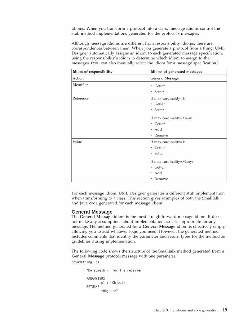
idioms. When you transform a protocol into a class, message idioms control thestub method implementations generated for the protocol’s messages.
Although message idioms are different from responsibility idioms, there arecorrespondences between them. When you generate a protocol from a thing, UMLDesigner automatically assigns an idiom to each generated message specification,using the responsibility’s idiom to determine which idiom to assign to themessages. (You can also manually select the idiom for a message specification.)
Idiom of responsibility Idioms of generated messages
Action General Message
Identifier v Getter
v Setter
Reference If max cardinality=1:
v Getter
v Setter
If max cardinality=Many:
v Getter
v Add
v Remove
Value If max cardinality=1:
v Getter
v Setter
If max cardinality=Many:
v Getter
v Add
v Remove
For each message idiom, UML Designer generates a different stub implementationwhen transforming to a class. This section gives examples of both the Smalltalkand Java code generated for each message idiom.
General MessageThe General Message idiom is the most straightforward message idiom. It doesnot make any assumptions about implementation, so it is appropriate for anymessage. The method generated for a General Message idiom is effectively empty,allowing you to add whatever logic you need. However, the generated methodincludes comments that identify the parameter and return types for the method asguidelines during implementation.
The following code shows the structure of the Smalltalk method generated from aGeneral Message protocol message with one parameter.doSomething: p1
"Do something for the receiver
PARAMETERSp1 : <Object>
RETURNS<Object>"
Chapter 3. Transforms and code generation 19
"Put user defined code here."
Following is the Java code generated from a General Message protocol messagewith one parameter./*** Do something for the receiver** @param aString**/
public void doSomething (String aString) {
/* Put user defined code here. */
}
AddThe Add idiom describes a message that adds an item to a collection. This idiom isautomatically assigned to the “add” messages generated for a responsibility withmaximum cardinality of many. An Add message must have one parameterrepresenting the object to be added. A protocol containing an Add message mustalso contain an attribute for the collection (this attribute is transformed into aninstance variable).
The following code shows the structure of the Smalltalk method generated from anAdd protocol message.addMessage: p1
"Add the argument, p1, to the receiver's collection of aVariable.
PARAMETERSp1 : <Object>
RETURNS<Object>"
self aVariable add: p1.
|p1.
Following is the Java code generated from an Add protocol message./*** Add the argument, p1, to the receiver's collection of aVariable.** @param p1**/
public void addMessage (Object p1) {this.aVariable.addElement(p1);
}
GetterThe Getter idiom describes a message that returns the value of an attribute. AGetter message cannot take any parameters, and the protocol must contain anattribute to contain the attribute whose value is returned (this attribute istransformed into an instance variable).
The following code shows the structure of the Smalltalk method generated from aGetter protocol message.
20 VisualAge Smalltalk: UML Designer User’s Guide
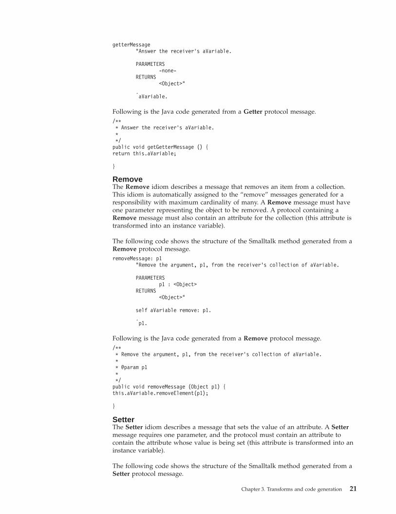
getterMessage"Answer the receiver's aVariable.
PARAMETERS-none-
RETURNS<Object>"
|aVariable.
Following is the Java code generated from a Getter protocol message./*** Answer the receiver's aVariable.**/
public void getGetterMessage () {return this.aVariable;
}
RemoveThe Remove idiom describes a message that removes an item from a collection.This idiom is automatically assigned to the “remove” messages generated for aresponsibility with maximum cardinality of many. A Remove message must haveone parameter representing the object to be removed. A protocol containing aRemove message must also contain an attribute for the collection (this attribute istransformed into an instance variable).
The following code shows the structure of the Smalltalk method generated from aRemove protocol message.removeMessage: p1
"Remove the argument, p1, from the receiver's collection of aVariable.
PARAMETERSp1 : <Object>
RETURNS<Object>"
self aVariable remove: p1.
|p1.
Following is the Java code generated from a Remove protocol message./*** Remove the argument, p1, from the receiver's collection of aVariable.** @param p1**/
public void removeMessage (Object p1) {this.aVariable.removeElement(p1);
}
SetterThe Setter idiom describes a message that sets the value of an attribute. A Settermessage requires one parameter, and the protocol must contain an attribute tocontain the attribute whose value is being set (this attribute is transformed into aninstance variable).
The following code shows the structure of the Smalltalk method generated from aSetter protocol message.
Chapter 3. Transforms and code generation 21
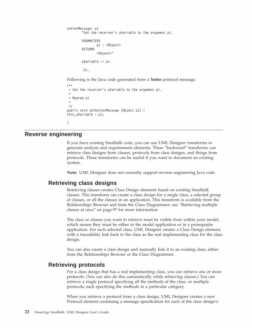
setterMessage: p1"Set the receiver's aVariable to the argument p1.
PARAMETERSp1 : <Object>
RETURNS<Object>"
aVariable := p1.
|p1.
Following is the Java code generated from a Setter protocol message./*** Set the receiver's aVariable to the argument p1.** @param p1**/
public void setSetterMessage (Object p1) {this.aVariable = p1;
}
Reverse engineeringIf you have existing Smalltalk code, you can use UML Designer transforms togenerate analysis and requirements elements. These “backward” transforms canretrieve class designs from classes, protocols from class designs, and things fromprotocols. These transforms can be useful if you want to document an existingsystem.
Note: UML Designer does not currently support reverse engineering Java code.
Retrieving class designsRetrieving classes creates Class Design elements based on existing Smalltalkclasses. This transform can create a class design for a single class, a selected groupof classes, or all the classes in an application. This transform is available from theRelationships Browser and from the Class Diagrammer; see “Retrieving multipleclasses at once” on page 97 for more information.
The class or classes you want to retrieve must be visible from within your model,which means they must be either in the model application or in a prerequisiteapplication. For each selected class, UML Designer creates a Class Design element,with a traceability link back to the class as the real implementing class for the classdesign.
You can also create a class design and manually link it to an existing class, eitherfrom the Relationships Browser or the Class Diagrammer.
Retrieving protocolsFor a class design that has a real implementing class, you can retrieve one or moreprotocols. (You can also do this automatically while retrieving classes.) You canretrieve a single protocol specifying all the methods of the class, or multipleprotocols, each specifying the methods in a particular category.
When you retrieve a protocol from a class design, UML Designer creates a newProtocol element containing a message specification for each of the class design’s
22 VisualAge Smalltalk: UML Designer User’s Guide
methods. It also creates a traceability link between the protocol and the conformingclass design. You can also select methods for retrieval by category; this is useful ifyou want to retrieve only some of the methods, or if you want to retrieve themethods into several distinct protocols. UML Designer creates conformance linksbetween the class design and all of the protocols to which it conforms.
When you retrieve a protocol, UML Designer attempts to assign types to thegenerated message parameters based on the names given to the parameters in theSmalltalk code, if a matching protocol exists in the model or a prerequisite model.For example, a method parameter called aString would result in a protocolmessage parameter of type <String>.
Retrieving thingsYou can also reverse engineer requirements elements by retrieving things fromprotocols. For each selected protocol, UML Designer creates a Thing element with atraceability link to the protocol. The generated Thing element is empty (noresponsibilities are generated).
Chapter 3. Transforms and code generation 23

24 VisualAge Smalltalk: UML Designer User’s Guide

Part 2. Using the UML Designer tools
© Copyright IBM Corp. 1997, 2000 25

26 VisualAge Smalltalk: UML Designer User’s Guide
Chapter 4. Using the browsers
UML Designer provides three browsers you can use to view, navigate, and edityour model elements:v The Relationships Browserv The Path Browserv The Hierarchy Browser
All three browsers display model elements and their contents, but each displaysthe relationships between elements differently.
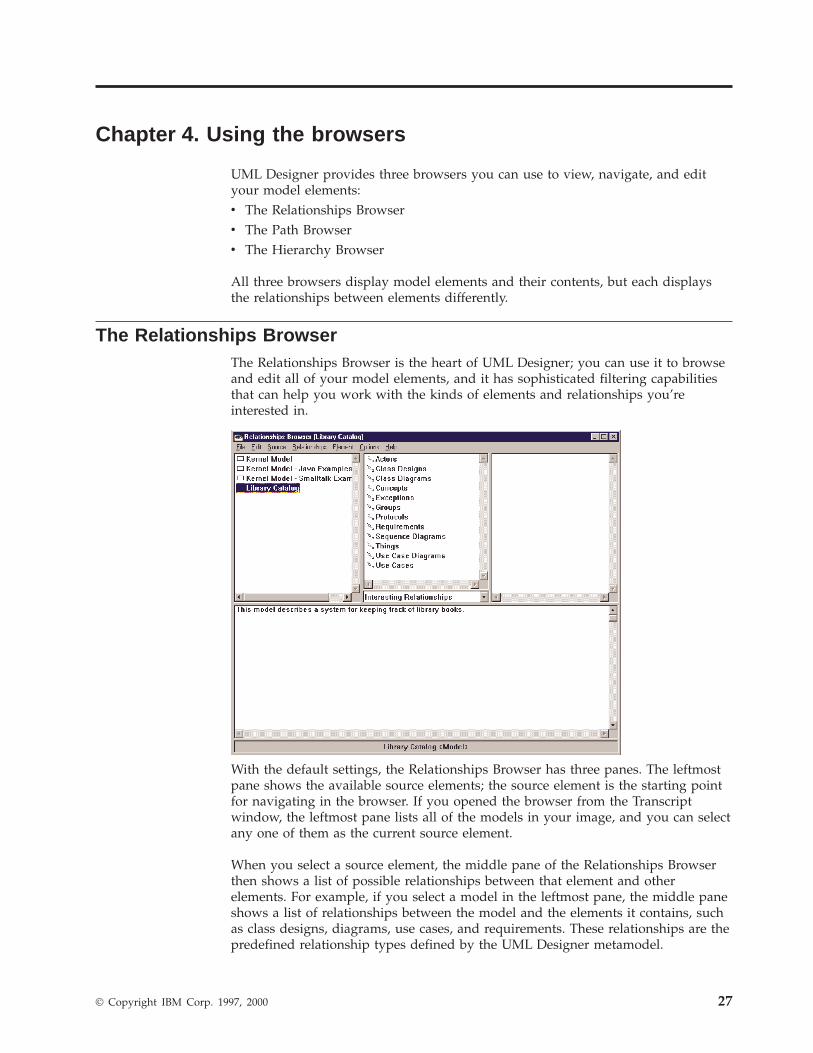
The Relationships BrowserThe Relationships Browser is the heart of UML Designer; you can use it to browseand edit all of your model elements, and it has sophisticated filtering capabilitiesthat can help you work with the kinds of elements and relationships you’reinterested in.
With the default settings, the Relationships Browser has three panes. The leftmostpane shows the available source elements; the source element is the starting pointfor navigating in the browser. If you opened the browser from the Transcriptwindow, the leftmost pane lists all of the models in your image, and you can selectany one of them as the current source element.
When you select a source element, the middle pane of the Relationships Browserthen shows a list of possible relationships between that element and otherelements. For example, if you select a model in the leftmost pane, the middle paneshows a list of relationships between the model and the elements it contains, suchas class designs, diagrams, use cases, and requirements. These relationships are thepredefined relationship types defined by the UML Designer metamodel.
© Copyright IBM Corp. 1997, 2000 27
The drop-down list at the bottom of the middle pane selects the relationship filterused to control which of the possible relationships are shown. Some types ofmodel elements have a large number of possible relationships, so this filter isuseful for viewing a subset of them. The default relationship filter is InterestingRelationships, which shows only the most useful relationships; most of the time,you can leave the filter set to this setting. Other settings can show other subsets ofthe possible relationships, or all of the possible relationships.
Note: The relationship filter is cumulative with other UML Designer filteringoptions, which are available from the menu bar. See “Filtering” on page 32for more information.
The bottom pane of the Relationships Browser is the hypertext pane. This panecontains any descriptive text that applies to the model, relationship, or modelelement currently selected. You can use the hypertext pane to write explanatorytext describing each element; the text can include hypertext links to other relatedmodel elements.
When you select one of the relationships from the middle pane, the rightmost paneshows all of the model elements that result from following the selected relationshipfrom the selected source element. For example, if you select Library Catalog in theleftmost pane and Class Diagrams in the middle pane, the rightmost pane lists all ofthe class diagrams defined in the Library Catalog model.
Spawning a new browserFrom any UML Designer browser, you can open a new browser with a selectedelement or elements as the source elements; this is called focusing. Focusing isuseful for following a long series of navigations, or getting a different view of anelement (for example, opening a Hierarchy Browser from a Relationships Browser).You can focus on any element displayed in a browser (a source element or a targetelement). There are several ways to do this:v Double-click on an element to open the default Focus browser for that element.
(For most elements, the default is the Relationships Browser, although for someit is different; for example, the default browser for a Publication element is theHierarchy Browser.) The selected element is source element in the new browser.
v Select one or more elements and then select Focus from the pop-up menu. Thisalso opens the default Focus browser for the selected elements, but this way youcan include multiple elements in the Source pane of the new browser.
v Select one or more elements and then select Open With from the pop-up menu.A cascaded menu appears from which you can select from all of the possibleUML Designer browsers (and any applicable Smalltalk browsers). Use thismethod if you want to use a browser other than the default Focus browser (forexample, if you want to open a Path Browser on a protocol).
Spawning a new browser on a relationshipYou can also open a new browser to display the results of following a specifiedrelationship. There are two ways you can browse a relationship:v To browse the destinations of a relationship, select a relationship and then select
Browse→Destinations from the pop-up menu. A browser opens showing thedestinations of the selected relationship in the source pane.
v To browse the connections for the relationship, select a relationship and thenselect Browse→Connections from the pop-up menu. A browser opens showingthe connections to the destination in the source pane.
28 VisualAge Smalltalk: UML Designer User’s Guide
You can select connection elements for navigating, deleting, and editing just asyou can other model elements. This makes it possible to browse and edit theproperties of an association without opening a diagrammer.
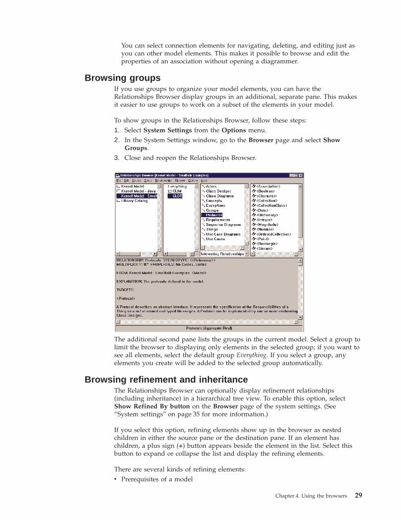
Browsing groupsIf you use groups to organize your model elements, you can have theRelationships Browser display groups in an additional, separate pane. This makesit easier to use groups to work on a subset of the elements in your model.
To show groups in the Relationships Browser, follow these steps:1. Select System Settings from the Options menu.2. In the System Settings window, go to the Browser page and select Show
Groups.3. Close and reopen the Relationships Browser.
The additional second pane lists the groups in the current model. Select a group tolimit the browser to displaying only elements in the selected group; if you want tosee all elements, select the default group Everything. If you select a group, anyelements you create will be added to the selected group automatically.
Browsing refinement and inheritanceThe Relationships Browser can optionally display refinement relationships(including inheritance) in a hierarchical tree view. To enable this option, selectShow Refined By button on the Browser page of the system settings. (See“System settings” on page 35 for more information.)
If you select this option, refining elements show up in the browser as nestedchildren in either the source pane or the destination pane. If an element haschildren, a plus sign (+) button appears beside the element in the list. Select thisbutton to expand or collapse the list and display the refining elements.
There are several kinds of refining elements:v Prerequisites of a model
Chapter 4. Using the browsers 29
v Refining protocols or messagesv Subclassing class designsv Extending use cases
The Path BrowserThe Path Browser is similar to the Relationships Browser, and it shows essentiallythe same information. However, it offers a more concise layout and a largercontext. The Path Browser is helpful when you need to work with nested elementsor complex relationships, because it allows you to view multiple layers ofnavigation within a single browser.
The Path Browser shows the successive navigation of not just one relationship, butof up to four relationships, starting from the selected source element. For example,you can use the Path Browser to browse a protocol, its message specifications, theparameters of a selected message, and the type of a selected parameter, all in thesame browser.
There are two ways to open the Path Browser:v In the Transcript window, select Path Browser from the UML Designer menu.v In any UML Designer browser or diagrammer, select a model element and then
select Open With→Path Browser from the pop-up menu.
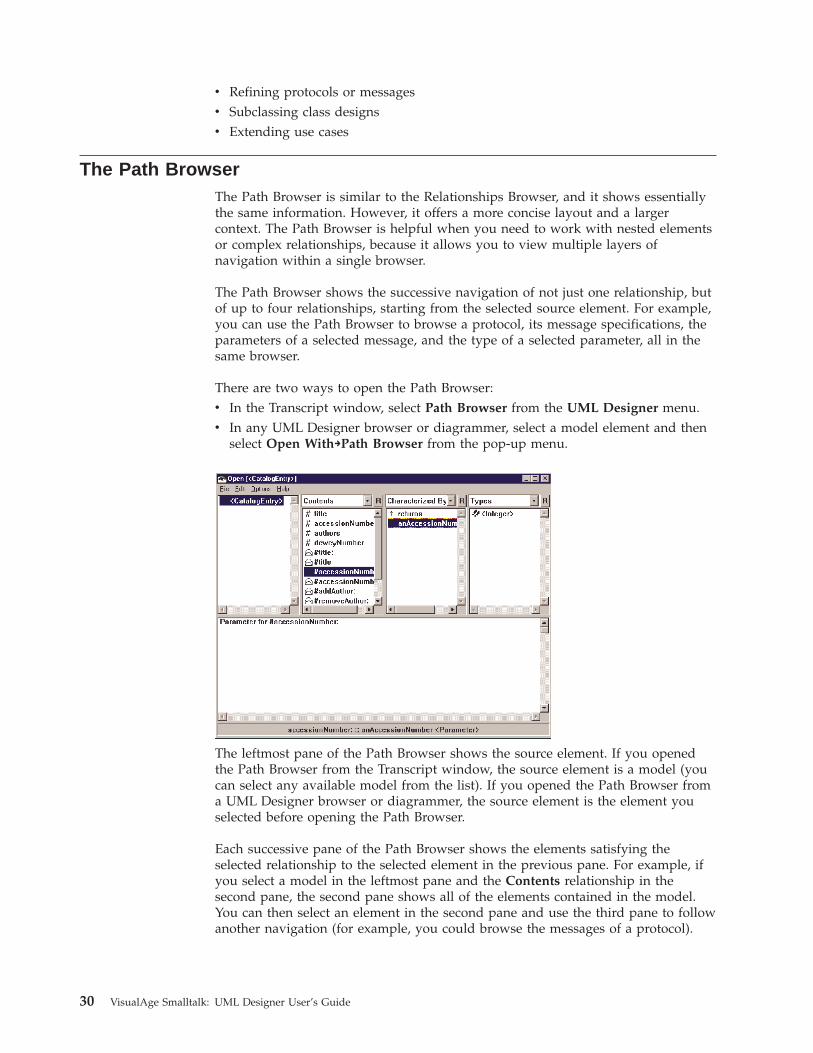
The leftmost pane of the Path Browser shows the source element. If you openedthe Path Browser from the Transcript window, the source element is a model (youcan select any available model from the list). If you opened the Path Browser froma UML Designer browser or diagrammer, the source element is the element youselected before opening the Path Browser.
Each successive pane of the Path Browser shows the elements satisfying theselected relationship to the selected element in the previous pane. For example, ifyou select a model in the leftmost pane and the Contents relationship in thesecond pane, the second pane shows all of the elements contained in the model.You can then select an element in the second pane and use the third pane to followanother navigation (for example, you could browse the messages of a protocol).
30 VisualAge Smalltalk: UML Designer User’s Guide
The relationships available in each pane of the Path Browser are the same as therelationships available in the Relationships Browser, and all of the same filteringoptions are available; select the R push button beside the relationship drop-downlist to select a filter. As with the Relationships Browser, the visible relationships arealso affected by UML Designer global filtering options (see “Filtering” on page 32for more information).
The Hierarchy BrowserThe Hierarchy Browser presents model elements in a hierarchical tree view, withelements arranged according to their containment relationships. This view issimilar to what you might see in a file browser. The Hierarchy Browser does notshow the actual relationships as elements; instead, it shows only the source anddestination model elements, arranged hierarchically from parent to child. TheHierarchy Browser is particularly useful for browsing and editing nested elementssuch as Publication elements. (See “Chapter 15. Publishing models” on page 103 formore information.
There are two ways to open a Hierarchy Browser:v In the Transcript window, select Hierarchy Browser from the UML Designer
menu.v In any UML Designer browser or diagrammer, select a model element and then
select Open With→Hierarchy Browser from the pop-up menu.
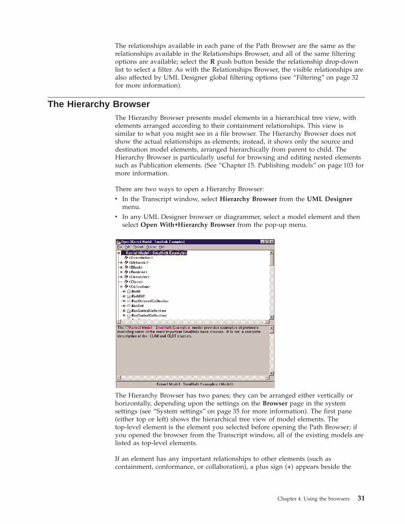
The Hierarchy Browser has two panes; they can be arranged either vertically orhorizontally, depending upon the settings on the Browser page in the systemsettings (see “System settings” on page 35 for more information). The first pane(either top or left) shows the hierarchical tree view of model elements. Thetop-level element is the element you selected before opening the Path Browser; ifyou opened the browser from the Transcript window, all of the existing models arelisted as top-level elements.
If an element has any important relationships to other elements (such ascontainment, conformance, or collaboration), a plus sign (+) appears beside the
Chapter 4. Using the browsers 31
element in the list. Click on the + to expand the list and see the related elements. Ifan element is linked to by multiple others, it might appear multiple times in thelist.
FilteringThe Relationships Browser and the Path Browser have powerful filtering functionsthat control the model elements and level of detail displayed. By using filtering,you can limit the browsers to displaying only the model elements you’re interestedin, based either on your relative level of advancement or your current task.
There are two ways of filtering the browser contents:v Filtering by taskv Filtering by browser level
You can use both kinds of filtering at the same time.
Filtering by taskTo filter by task, select Tasks from the Options menu. This displayed a cascadedmenu from which you can select one of the following tasks:
All Not actually a task, All specifies no filtering. This is the default setting andcauses all relationships and elements to appear (subject to other selectedfilters).
RequirementsSelect the Requirements task filter to see only relationships and elementsin the requirements model (such as things and use cases).
AnalysisSelect the Analysis task filter to see only relationships and elements in theanalysis model (such as protocols).
DesignSelect the Design task filter to see only relationships and elements in thedesign model (such as class designs).
DiagrammingSelect the Diagramming task filter to see only relationships and elementsrelated to creating and publishing diagrams (such as diagram elements).
OrganizingSelect the Organizing task filter to see only relationships and elementsrelated to organizing your model elements (such as groups).
Filtering by browser levelThe Relationships Browser and the Path Browser can display relationships andelements according to five different levels of detail. To change the browser level,select Levels from the Options menu; this displays a cascaded menu from whichyou can select the browser level you want to use. This setting globally affects allRelationships Browsers and Path Browsers.
The higher the browser level, the more relationships appear in the RelationshipsBrowser and Path Browser. These levels are cumulative: each browser levelincludes all of the relationships displayed at the lower levels, plus additionalrelationships. Generally, you should use the lowest browser level that includes allof the relationships you want to use, in order to avoid unnecessary clutter.
32 VisualAge Smalltalk: UML Designer User’s Guide
Note: Filtering by browser level works in conjunction with other UML Designerfiltering mechanisms (such as filtering by task or selecting a relationshipfilter in the Relationships Browser). To see all of the relationships includedat the current browser level, you must do the following:v Select Tasks→All from the Options menu to disable task filtering.v Select All Relationships in the Relationships Browser.
Level 1: BasicBrowser level 1 includes only the basic structural relationships of the model. Thisincludes relationships that lead to semantically interesting direct children of thesource element (containment relationships); it also includes associations of thesource element.
It does not include cross-linking relationships, relationships that lead only to″view″ elements such as diagrams and publications, or cross-referencing andtraceability relationships (see Level 2 for more information).
For example, Level 1 includes:v Actorsv Things and responsibilitiesv Protocols and messagesv Simple associations
Level 2: GeneralBrowser level 2 adds additional semantic model relationships, as well asrelationships to ″view″ elements such as publications and diagrams. It alsoincludes semantically important cross-linking relationships (direct references otherthan containment and hypertext relationships, such as a “satisfies” link from a usecase to a requirement), as well as a few cross-reference relationships (direct andindirect connections that help in understanding the model, such as traceability and“used by” links). This level is the default when you install UML Designer.
For example, Level 2 includes:v Diagram elementsv Exceptionsv Conformance relationshipsv Collaboration relationships
Level 3: Cross-referenceBrowser level 3 adds additional relationships that show how model elementsdepend upon one another. This can be helpful with a large or complex model. Forexample, Level 3 includes:v Dependencies between modelsv Constraintsv Hypertext references between elements
Level 4: MetaBrowser level 4 adds some additional relationships that make it possible tonavigate some of the metamodel elements associated with your model element.This includes the filters themselves, each a relationship in the metamodel (you canselect a filter to see the relationships available with that filter).
Chapter 4. Using the browsers 33
Level 5: AdvancedBrowser level 5 includes all of the public UML Designer relationships. Thisincludes relationships that show the available elements of a particular type in themodel, according to the scoping criteria of the element and its parent relationships.
For example, level 5 includes:v Available messagesv Available return valuesv Available responsibilitiesv Available publication topics
Checking consistencySome circumstances can cause a model to have inconsistencies, such as missinglink destinations, out-of-scope references, or missing prerequisites. For example,inconsistencies can be caused by loading a back-level edition or making changes toa model with standard ENVY browsers rather than the UML Designer browsers.
UML Designer provides a tool to check for inconsistencies. To check consistency,select the model or element you want to check and then select Check Consistencyfrom the pop-up menu. (You can also select Check Consistency from the Source orElement menu of the Relationships Browser, depending upon where the elementyou want to check appears. Checking an element also checks all of its children.
When the consistency check finishes, a window appears listing any errors andasking whether you want to browse them. You have two choices:v Select Yes to open a Hierarchy Browser from which you can repair the errors
manually.v Select No to have UML Designer attempt to fix the errors automatically. If any
cannot be repaired automatically, UML Designer will then open a HierarchyBrowser to display the remaining errors so you can repair them manually.
Browsing inconsistenciesIf you select Yes, a Hierarchy Browser opens listing each error, with the involvedelements listed as children of the error. The text pane of the browser gives detailsabout the error and suggests what you might do to fix it.
Depending upon the nature of the error, there may be two different ways ofcorrecting it.v To correct the error by deleting elements, select the error in the browser and
then select Make Consistent By Deleting from the pop-up menu. (This option isavailable only if deleting an element is a viable option for correcting theproblem and will not create additional errors.)
v To attempt to repair the error automatically, select the error and then selectMake Consistent By Repairing from the pop-up menu. UML Designer willattempt to repair the error; an error message appears if it is unable to do so.
34 VisualAge Smalltalk: UML Designer User’s Guide
Repairing inconsistenciesFollowing are the inconsistencies you are most likely to encounter:
Error Message Explanation Possible Repairs
Missing Object On Diagram A diagram points to one ormore missing objects.
v Reload the missing objects.
v Delete the figure.
Already Deleted An object has been markedas deleted but is still in thesystem in an inconsistentstate.
Reload the object.
Missing Destination One of the objects in arelationship is missing.
v Load the missing object.
v Unlink from the missingobject.
Missing Parent The parent of an object ismissing.
Reload the parent.
Orphan An object is not referencedby any other object (it has noparent), possibly because ofdamaged links.
Repair any damaged links. Ifno links are damaged, deletethe orphaned object.
Out Of Scope A relationship references anelement that is not visible(not in the same model orone of its prerequisites).
v Move the referencedelement so it becomesvisible.
v Change the prerequisites.
v Remove the link.
Missing Back ReferenceRelationship
One element points toanother, but the second doesnot point back to the first.
Select Make Consistent ByRepairing to automaticallycreate the inverse link.
Modified But Not Saved An element contains changesthat have not been saved.
Save the element.
No Released Edition An element has not beenreleased to its parent. Thiscan happen if you versionelements with ENVYbrowsers.
Select Make Consistent ByRepairing to release thecurrently loaded edition.
Association Attachment LinkError
The source or destination ofan association is incorrect.
v Correct the association.
v Delete the association.
System settingsIn any of the three UML Designer browsers, you can select Options→SystemSettings to display the UML Designer System Settings window. From this windowyou can control options that affect how the browsers and diagrams displayinformation and other configurable UML Designer settings. Each tab in the SystemSettings window controls a different aspect of the UML Designer environment:
UI Controls general user-interface options. This includes default filtering forthe Relationships Browser and Path Browser, as well as general options fordiagramming and UML Designer dialogs.
BrowserControls the appearance of the UML Designer browsers. This includes
Chapter 4. Using the browsers 35
whether the Groups pane appears in the Relationships Browser, whether toshow refining elements, and the layout of the Hierarchy Browser.
Color/FontControls the appearance of the screen fonts used in the UML Designerbrowsers and diagrammers. You can specify fonts for three different kindsof emphasis: hypertext links, figure captions, and missing object captions.
GeneralControls options related to default link labels and consistency checking.See “Association labeling” on page 41 for more information.
SyntaxControls the syntax used to parse and display protocol messages. You canselect any one of the following options:v Standard UML syntaxv Smalltalk-style syntaxv Java-style syntax
Code GenerationControls options related to transforms that generate implementationclasses. These options affect:v The default prerequisite for any new modelsv The specification of protocol messages generated from responsibilitiesv The availability and appearance of transform dialogsv The target language for generated code (Java or Smalltalk)
36 VisualAge Smalltalk: UML Designer User’s Guide
Chapter 5. Using the UML Designer diagrammers
UML Designer supports the creation of three types of UML-compliant diagrams:v Use case diagramsv Class diagramsv Sequence diagrams
Each type of diagram presents models in a different way, and each has a separatediagramming tool. However, the three diagrammers (and the three types ofdiagrams) share many common characteristics.
DiagramsEach model element in a UML Designer diagram is represented by a figure, agraphical representation based on UML notation. A figure is attached to anunderlying model element, from which it takes most of its properties. Normally,each model element can be represented by only one figure in a single diagram.
A figure also has additional characteristics of its own that control its visualappearance. For example, the figure controls which aspects of the underlyingmodel element appear on the diagram, as well as purely visual attributes such ascolor.
From a diagrammer, you can edit both the visual attributes of the figures; you canalso open browsers (using Open With) and make changes to the underlying modelelements.
A diagram has two types of figures:v A node figure represents a structural model element (such as an actor, use case,
or class design).v A connector figure joins two node figures and represents a link or association
between model elements. Each connector figure is owned by one of the nodefigures it connects to.
Note: The term link here refers to a semantic connection between two objects (inUML terms, a link is an instance of an association). This is distinct from ahypertext link, which is not a formal semantic connection but simply anavigational reference. Hypertext links are not represented on diagrams.
Figures can also have adornments, which are labels and other decorations thatcarry semantic meaning on the diagram. The visual attributes of a figure (its font,color, and position on the diagram) exist independently of the underlying model.
Adornments help to make a class diagram more understandable, and they conveyadditional information about the model elements, including additional UMLsemantics; for example, they can show the navigability and multiplicity of anassociation. You can specify whether or not most adornments appear on a figure;however, the properties described by adornments exist in the model, whether ornot the adornments themselves are displayed.
Using the UML Designer diagrammers, you can build models in two differentways:
© Copyright IBM Corp. 1997, 2000 37
v You can add figures for existing model elements. This technique is useful fordocumenting an existing model.
v You can add new figures and create new model elements for them at the sametime. You can use this technique to build a new model graphically.
Using the diagrammersIn order to build a diagram, you must first create a Diagram element in yourmodel. To create a diagram, do one of the following:v In the Relationships Browser (or another UML Designer browser), select a model
and then select New→Class Diagram, New→Sequence Diagram, or New→UseCase Diagram from the pop-up menu.
v In the middle pane of the Relationships Browser, select the type of diagram youwant to create and then select New from the pop-up menu.
To open a diagram for editing, double-click on the Diagram element in thebrowser.
Adding a node figureThere are several ways to add a node figure to a diagram:v Manually creating a new node figure and attaching it to a model element
(selected from a list or named directly)v Copying a node figure from another diagram along with its attached modelv Copying a model element from a browser and pasting it into the diagram as a
figurev Selecting Hide/Show Relationships to show an existing or candidate
relationship to an element not already on the diagram
Once you have added a figure, you can move it on the drawing surface to makeyour diagram more readable.
Manually creating a node figureTo manually create a node figure and attach it to a model element, follow thesesteps:1. Select the figure you want from the tool bar. (If you prefer, you can select
Create Node Figure from the Tools menu and then select the figure you wantfrom the cascaded menu.)
2. Position the mouse pointer where you want the figure to appear (in an emptyarea of the drawing surface) and then click mouse button 1.When first added, an unattached figure is labeled with a question mark (?).
3. If you know the name of the model element you want to attach the figure to,hold down the Alt key and click mouse button 1 on the figure label to directlyedit the label. UML Designer automatically attaches the figure to the elementthat matches the name you specify.
4. If you want to select from a list of available elements, select Attach from thepop-up menu of the figure. In the window that appears, select the modelelement you want to attach to the figure. (You can also specify that you want tocreate a new element.)
Note: This list does not normally include any model elements alreadyrepresented on the diagram.
38 VisualAge Smalltalk: UML Designer User’s Guide
Copying a node figure from another diagramTo copy an existing node figure from another diagram, follow these steps:1. Select the figure you want to copy in the source diagram.2. Select Copy from the Edit menu, or from the pop-up menu.3. Go to the target diagram and place the mouse pointer in the location where
you want to paste the figure.4. Select Paste Here from the pop-up menu. (You can also select Paste from the
Edit menu and then move the figure where you want it.)
The figure is copied along with its visual properties (color and font), and the newcopy is attached to the same model element as the original figure. (If the attachedelement is in a different model from that of the diagram, the model name appearsin brackets.)
Copying a model element to a node figureTo copy a model element and paste it as a new node figure, follow these steps:1. In the Relationships Browser or another UML Designer browser, select the
element you want to create a figure for.2. Select Copy from the Element menu, or from the pop-up menu.3. Go to the target diagram and place the mouse pointer in the location where
you want to paste the figure.4. Select Paste Here from the pop-up menu. (You can also select Paste from the
Edit menu and then move the figure where you want it.)
The new figure is automatically attached to the model element you selected. (If theattached element is in a different model from that of the diagram, the model nameappears in brackets.)
Adding a node figure with Hide/Show RelationshipsYou can use the Hide/Show Relationships choice on the pop-up menu of a nodefigure to create connector figures for existing or new relationships (see “Adding aconnector with Hide/Show Relationships” on page 40 for more information). If theelement at the other end of the relationship is not already represented by a nodefigure, UML Designer automatically creates one and adds it to your diagram.
Adding a connector figureThere are several ways to add a connector figure to a diagram:v Manually creating a connector figure between two node figuresv Copying a connector figure from another diagramv Copying a relationship from a browser and pasting it as a connector figurev Displaying an existing or candidate connection by selecting Hide/Show
Relationships on the pop-up menu of a node figure
To reroute the path of a connector figure in a class diagram or use case diagram,select the figure and then drag its selection handles.
Manually creating a new connector figureTo add a connector figure to a diagram, follow these steps:1. Select the figure you want from the tool bar. (If you prefer, you can select
Select Relationship Figure from the Tools menu and then select the figure youwant from the cascaded menu.)
Chapter 5. Using the UML Designer diagrammers 39
2. Position the mouse pointer on the figure representing the source (owner) of therelationship. For example, a class design owns its conformance relationships toprotocols; either node can be the owner of a simple association.
3. Click mouse button 1 to connect the source end of the relationship.4. Move the mouse pointer to the figure representing the destination of the
relationship.5. Click mouse button 1 to complete the relationship.
Copying a connector figure from another diagramTo copy an existing connector figure from another diagram, follow these steps:1. Select the connector figure you want to copy in the source diagram.2. Select Copy from the Edit menu, or from the pop-up menu.3. Go to the target diagram.4. Select Paste Here from the pop-up menu or Paste from the Edit menu.
The connector figure is copied along with its adornments. If both endpointsalready appear on the diagram, the connector automatically connects them; ifeither or both are missing, they are copied along with the connector figure.
Copying a relationship to a connector figureTo copy a relationship between model elements and paste it as a new connectorfigure, follow these steps:1. In the Relationships Browser, select the relationship you want to create a figure
for. (You can select a relationship by browsing connections; see “Spawning anew browser on a relationship” on page 28 for more information.)
2. Select Copy from the Source menu, or from the pop-up menu.3. Go to the target diagram.4. Select Paste Here from the pop-up menu or Paste from the Edit menu.
A new connector figure is created for the relationship you selected. If either or bothof the elements involved in the relationship are not yet represented in the diagram,node figures for them are created as well.
Adding a connector with Hide/Show RelationshipsYou can create connector figures for existing or candidate relationships. To do this,follow these steps:1. Select the node figure you want to connect to.2. Select Hide/Show Relationships from the pop-up menu.
A window appears listing any existing relationships (associations and links)involving the selected element, followed by any identified candidaterelationships. A candidate relationship is identified with a plus sign (+).A candidate relationship is a relationship that doesn’t yet exist in the model,but can be created automatically. Candidate relationships include commonlyused “default” relationships. By selecting a candidate relationship, you canquickly create the relationship, a connector figure for the relationship, and insome cases, a node figure for the other endpoint. For example, you can create(and link to) a new instance of a class design.
3. Select the relationship for which you want to create a connector figure from theHidden Relationships list. (You can also select multiple relationships at once.)
4. Select >> to add the relationship to the Shown Relationships list.5. Select OK.
40 VisualAge Smalltalk: UML Designer User’s Guide
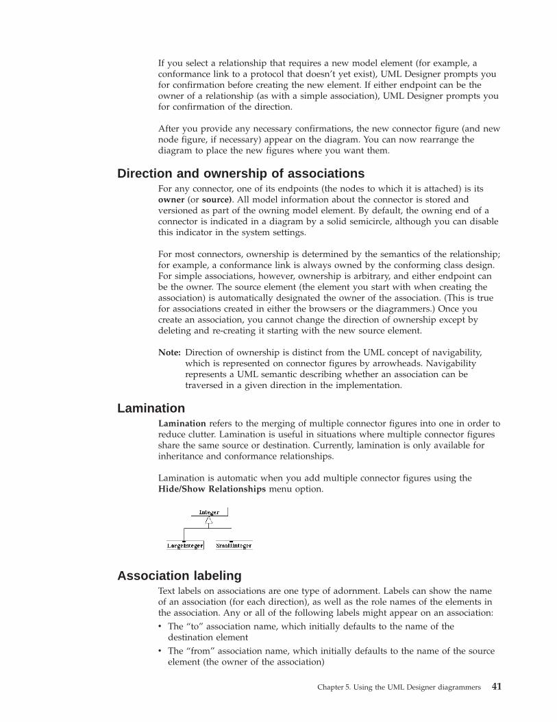
If you select a relationship that requires a new model element (for example, aconformance link to a protocol that doesn’t yet exist), UML Designer prompts youfor confirmation before creating the new element. If either endpoint can be theowner of a relationship (as with a simple association), UML Designer prompts youfor confirmation of the direction.
After you provide any necessary confirmations, the new connector figure (and newnode figure, if necessary) appear on the diagram. You can now rearrange thediagram to place the new figures where you want them.
Direction and ownership of associationsFor any connector, one of its endpoints (the nodes to which it is attached) is itsowner (or source). All model information about the connector is stored andversioned as part of the owning model element. By default, the owning end of aconnector is indicated in a diagram by a solid semicircle, although you can disablethis indicator in the system settings.
For most connectors, ownership is determined by the semantics of the relationship;for example, a conformance link is always owned by the conforming class design.For simple associations, however, ownership is arbitrary, and either endpoint canbe the owner. The source element (the element you start with when creating theassociation) is automatically designated the owner of the association. (This is truefor associations created in either the browsers or the diagrammers.) Once youcreate an association, you cannot change the direction of ownership except bydeleting and re-creating it starting with the new source element.
Note: Direction of ownership is distinct from the UML concept of navigability,which is represented on connector figures by arrowheads. Navigabilityrepresents a UML semantic describing whether an association can betraversed in a given direction in the implementation.
LaminationLamination refers to the merging of multiple connector figures into one in order toreduce clutter. Lamination is useful in situations where multiple connector figuresshare the same source or destination. Currently, lamination is only available forinheritance and conformance relationships.
Lamination is automatic when you add multiple connector figures using theHide/Show Relationships menu option.
Association labelingText labels on associations are one type of adornment. Labels can show the nameof an association (for each direction), as well as the role names of the elements inthe association. Any or all of the following labels might appear on an association:v The “to” association name, which initially defaults to the name of the
destination elementv The “from” association name, which initially defaults to the name of the source
element (the owner of the association)
Chapter 5. Using the UML Designer diagrammers 41
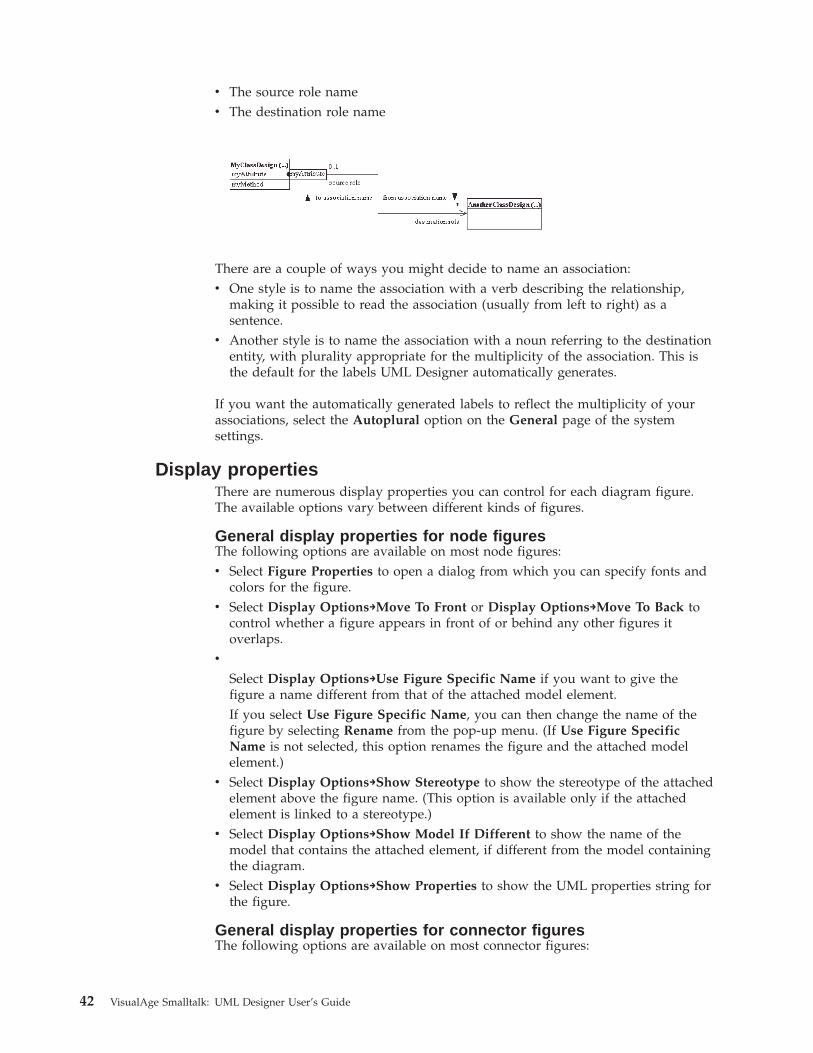
v The source role namev The destination role name
There are a couple of ways you might decide to name an association:v One style is to name the association with a verb describing the relationship,
making it possible to read the association (usually from left to right) as asentence.
v Another style is to name the association with a noun referring to the destinationentity, with plurality appropriate for the multiplicity of the association. This isthe default for the labels UML Designer automatically generates.
If you want the automatically generated labels to reflect the multiplicity of yourassociations, select the Autoplural option on the General page of the systemsettings.
Display propertiesThere are numerous display properties you can control for each diagram figure.The available options vary between different kinds of figures.
General display properties for node figuresThe following options are available on most node figures:v Select Figure Properties to open a dialog from which you can specify fonts and
colors for the figure.v Select Display Options→Move To Front or Display Options→Move To Back to
control whether a figure appears in front of or behind any other figures itoverlaps.
v
Select Display Options→Use Figure Specific Name if you want to give thefigure a name different from that of the attached model element.If you select Use Figure Specific Name, you can then change the name of thefigure by selecting Rename from the pop-up menu. (If Use Figure SpecificName is not selected, this option renames the figure and the attached modelelement.)
v Select Display Options→Show Stereotype to show the stereotype of the attachedelement above the figure name. (This option is available only if the attachedelement is linked to a stereotype.)
v Select Display Options→Show Model If Different to show the name of themodel that contains the attached element, if different from the model containingthe diagram.
v Select Display Options→Show Properties to show the UML properties string forthe figure.
General display properties for connector figuresThe following options are available on most connector figures:
42 VisualAge Smalltalk: UML Designer User’s Guide
v Select Figure Properties to open a dialog from which you can specify fonts andcolors for the figure.
v Select Role→Edit From or Role→Edit To to edit the role names of the source anddestination endpoints.
v Select Role→Show From or Role→Show To to control whether the source anddestination role labels are displayed.
v Select Navigation to specify the navigability of the connector. You can specifyany one of the following navigability options:– None (no navigability)– From (navigable toward the source element)– To (navigable toward the destination element)– Both (navigable in either direction)
Select Navigation→Show Navigation Arrow to control whether navigability isindicated on the diagram by an arrowhead.
v Select Show All Labels or Hide All Labels to control whether any labels appearon the connector figure.
AlignmentIn addition to manually moving figures on a diagram, you can also use the Formatmenu to automatically arrange your figures for readability or neatness.v Select Align Horizontal to arrange two or more selected figures in a straight
horizontal line. You can align the top edges, bottom edges, or centers of thefigures.
v Select Align Vertical to arrange two or more selected figures in a straightvertical line. You can align the left edges, right edges, or centers of the figures.
v Select Align To Grid to arrange one or more selected figures to the alignmentgrid. (The grid is not visible, but it provides a quick way to align figures topreset rows and columns.)
v Select Distribute By Edges to arrange three or more figures so the spacebetween them is equal. You can select to arrange the figures horizontally (selectLeft To Right) or vertically (select Top To Bottom).
v Select Distribute By Centers to arrange three or more figures so the spacebetween their centers is equal. You can select to arrange the figures horizontally(select Left To Right) or vertically (select Top To Bottom).
You can also interactively align figures by selecting Format from the Format menu.This opens the Format window, from which you can select the alignment optionsyou want to apply to the selected figure or figures.
Deleting figuresThere are two ways to delete a figure from a diagram.v To delete the figure but leave the attached model element, select the figure and
then select Delete Figure from the pop-up menu (or press the Backspace key).If you use this option, you can re-add the deleted figure, and only its visualproperties are lost.
v To delete the figure and its attached model element, select the figure and thenselect Delete Figure And Model (or press the Del key).If you use this option, you cannot re-add the figure unless you also re-create (orreload) the element it represents.
Chapter 5. Using the UML Designer diagrammers 43
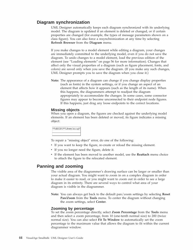
Diagram synchronizationUML Designer automatically keeps each diagram synchronized with its underlyingmodel. The diagram is updated if an element is deleted or changed, or if certainproperties are changed (for example, the types of message parameters shown on aclass figure). You can also force a resynchronization at any time by selectingRefresh Browser from the Diagram menu.
If you make changes to a model element while editing a diagram, your changesare immediately committed to the underlying model, even if you do not save thediagram. To undo changes to a model element, load the previous edition of theelement (see “Loading elements” on page 56 for more information). Changes thataffect only the visual properties of a diagram (such as figure placement, fonts, andcolors) are saved only when you save the diagram. (If you make any such changes,UML Designer prompts you to save the diagram when you close it.)
Note: The appearance of a diagram can change if you change display properties(such as fonts) in the system settings, or if you change an aspect of anelement that affects how it appears (such as the length of its name). Whenthis happens, the diagrammers attempt to readjust the diagramappropriately to accommodate the changes. In some cases, some connectorfigures may appear to become unconnected to their endpoint node figures.If this happens, just drag any loose endpoints to the correct locations.
Missing objectsWhen you open a diagram, the figures are checked against the underlying modelelements. If an element has been deleted or moved, its figure indicates a missingobject:
To repair a ″missing object″ error, do one of the following:v If you want to keep the figure, re-create or reload the missing element.v If you no longer need the figure, delete it.v If the element has been moved to another model, use the Reattach menu choice
to attach the figure to the relocated element.
Panning and zoomingThe visible area of the diagrammer’s drawing surface can be larger or smaller thanyour actual diagram. You might want to zoom in on a complex diagram in orderto make it easier to read, or you might want to zoom out in order to see a largediagram in its entirety. There are several ways to control what area of yourdiagram is visible in the diagrammer.
Note: You can always get back to the default pan/zoom settings by selecting ResetPan/Zoom from the Tools menu. To center the diagram without changingthe zoom settings, select Center.
Zooming by percentageTo set the zoom percentage directly, select Zoom Percentage from the Tools menuand then select a zoom percentage, from 10 (one-tenth normal size) to 200 (twicenormal size). You can also select Fit To Window to automatically set the zoompercentage to the maximum value that allows the diagram to fit within the currentdiagrammer window.
44 VisualAge Smalltalk: UML Designer User’s Guide
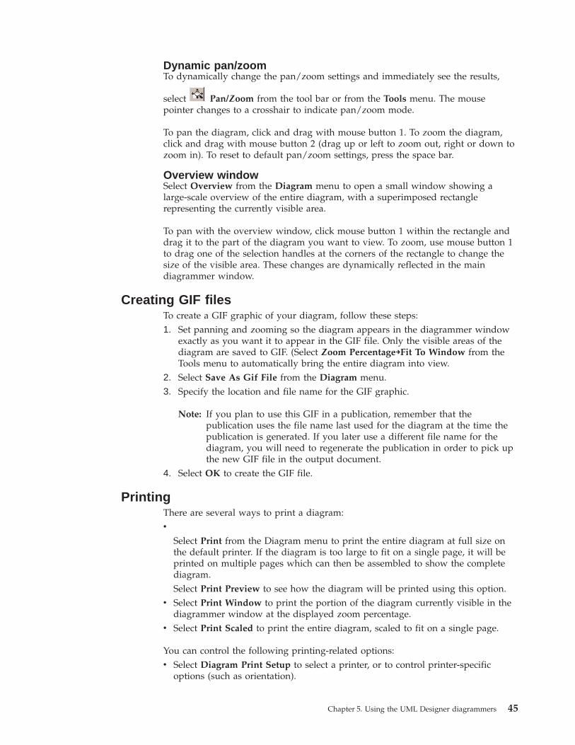
Dynamic pan/zoomTo dynamically change the pan/zoom settings and immediately see the results,
select Pan/Zoom from the tool bar or from the Tools menu. The mousepointer changes to a crosshair to indicate pan/zoom mode.
To pan the diagram, click and drag with mouse button 1. To zoom the diagram,click and drag with mouse button 2 (drag up or left to zoom out, right or down tozoom in). To reset to default pan/zoom settings, press the space bar.
Overview windowSelect Overview from the Diagram menu to open a small window showing alarge-scale overview of the entire diagram, with a superimposed rectanglerepresenting the currently visible area.
To pan with the overview window, click mouse button 1 within the rectangle anddrag it to the part of the diagram you want to view. To zoom, use mouse button 1to drag one of the selection handles at the corners of the rectangle to change thesize of the visible area. These changes are dynamically reflected in the maindiagrammer window.
Creating GIF filesTo create a GIF graphic of your diagram, follow these steps:1. Set panning and zooming so the diagram appears in the diagrammer window
exactly as you want it to appear in the GIF file. Only the visible areas of thediagram are saved to GIF. (Select Zoom Percentage→Fit To Window from theTools menu to automatically bring the entire diagram into view.
2. Select Save As Gif File from the Diagram menu.3. Specify the location and file name for the GIF graphic.
Note: If you plan to use this GIF in a publication, remember that thepublication uses the file name last used for the diagram at the time thepublication is generated. If you later use a different file name for thediagram, you will need to regenerate the publication in order to pick upthe new GIF file in the output document.
4. Select OK to create the GIF file.
PrintingThere are several ways to print a diagram:v
Select Print from the Diagram menu to print the entire diagram at full size onthe default printer. If the diagram is too large to fit on a single page, it will beprinted on multiple pages which can then be assembled to show the completediagram.Select Print Preview to see how the diagram will be printed using this option.
v Select Print Window to print the portion of the diagram currently visible in thediagrammer window at the displayed zoom percentage.
v Select Print Scaled to print the entire diagram, scaled to fit on a single page.
You can control the following printing-related options:v Select Diagram Print Setup to select a printer, or to control printer-specific
options (such as orientation).
Chapter 5. Using the UML Designer diagrammers 45
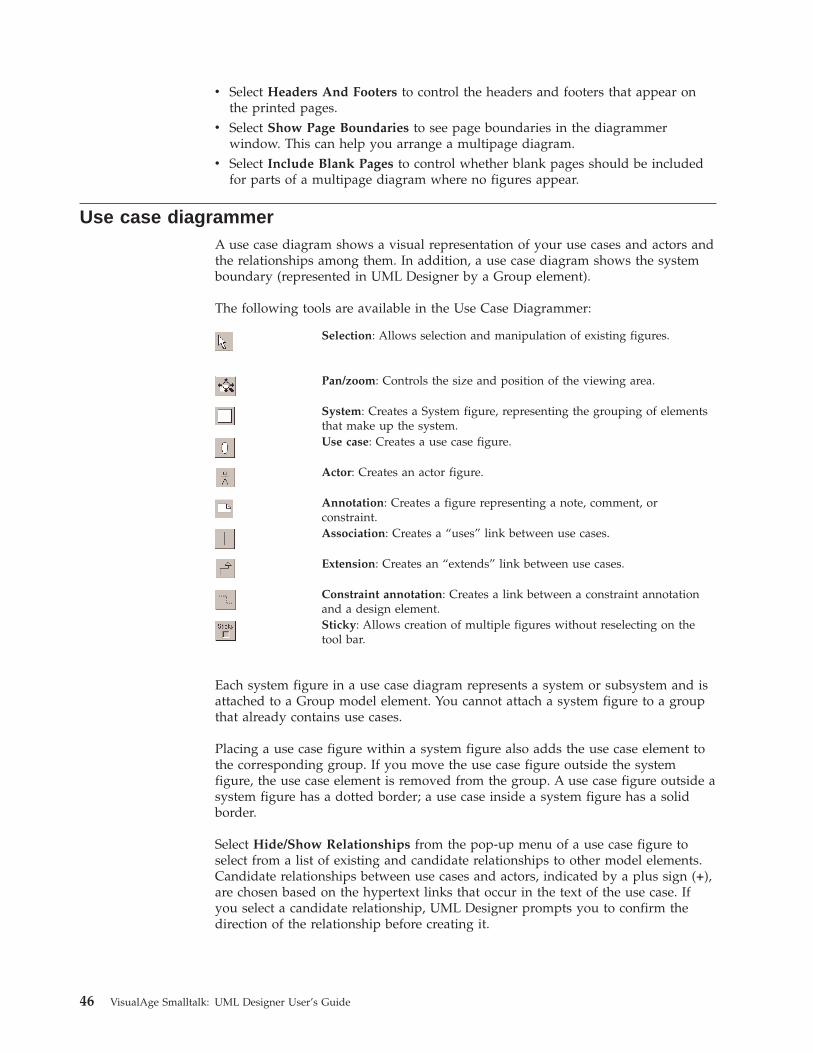
v Select Headers And Footers to control the headers and footers that appear onthe printed pages.
v Select Show Page Boundaries to see page boundaries in the diagrammerwindow. This can help you arrange a multipage diagram.
v Select Include Blank Pages to control whether blank pages should be includedfor parts of a multipage diagram where no figures appear.
Use case diagrammerA use case diagram shows a visual representation of your use cases and actors andthe relationships among them. In addition, a use case diagram shows the systemboundary (represented in UML Designer by a Group element).
The following tools are available in the Use Case Diagrammer:
Selection: Allows selection and manipulation of existing figures.
Pan/zoom: Controls the size and position of the viewing area.
System: Creates a System figure, representing the grouping of elementsthat make up the system.Use case: Creates a use case figure.
Actor: Creates an actor figure.
Annotation: Creates a figure representing a note, comment, orconstraint.Association: Creates a “uses” link between use cases.
Extension: Creates an “extends” link between use cases.
Constraint annotation: Creates a link between a constraint annotationand a design element.Sticky: Allows creation of multiple figures without reselecting on thetool bar.
Each system figure in a use case diagram represents a system or subsystem and isattached to a Group model element. You cannot attach a system figure to a groupthat already contains use cases.
Placing a use case figure within a system figure also adds the use case element tothe corresponding group. If you move the use case figure outside the systemfigure, the use case element is removed from the group. A use case figure outside asystem figure has a dotted border; a use case inside a system figure has a solidborder.
Select Hide/Show Relationships from the pop-up menu of a use case figure toselect from a list of existing and candidate relationships to other model elements.Candidate relationships between use cases and actors, indicated by a plus sign (+),are chosen based on the hypertext links that occur in the text of the use case. Ifyou select a candidate relationship, UML Designer prompts you to confirm thedirection of the relationship before creating it.
46 VisualAge Smalltalk: UML Designer User’s Guide
Class diagrammerA class diagram is a visual representation of the class and protocol objects in yoursystem and their relationships to one another. For example, a class diagram canshow:v classes and methodsv protocols and message specificationsv class instancesv associations between classes, protocols, or instancesv protocol conformancev instantiationv dependenciesv refinement and subclassing
The Class Diagrammer provides sophisticated capabilities for filtering whichaspects of your model elements you want to appear on the diagram, as well as thelevel of detail displayed. For example, you can control which attributes andmethods are shown for class and protocol figures, and whether type information isincluded (and in what syntax).
The following tools are available in the Class Diagrammer:
Selection: Allows selection and manipulation of existing figures.
Pan/zoom: Controls the size and position of the viewing area.
Protocol: Creates a figure representing a protocol.
Class: Creates a figure representing a class design.
Object : Creates a figure representing an object instance.
Annotation: Creates a figure representing a note, comment, orconstraint.Inheritance: Creates a figure representing an inheritance relationshipbetween classes.Conformance : Creates a figure representing a conformance relationshipbetween a class and a protocol.Dependency: Creates a figure representing a dependency relationshipbetween a class and a protocol.Association: Creates a figure representing a simple associationrelationship between classes.Aggregation: Creates a figure representing an aggregation relationshipbetween classes.Constraint annotation: Creates a link between a constraint annotationand a design element.Sticky : Allows creation of multiple figures without reselecting on thetool bar.
Class figure display propertiesIn addition to the general display properties, the following display properties areavailable for class and instance figures:v Select Display Options→Name Only to show only the name of the class. This
option hides any additional information (such as method names).
Chapter 5. Using the UML Designer diagrammers 47
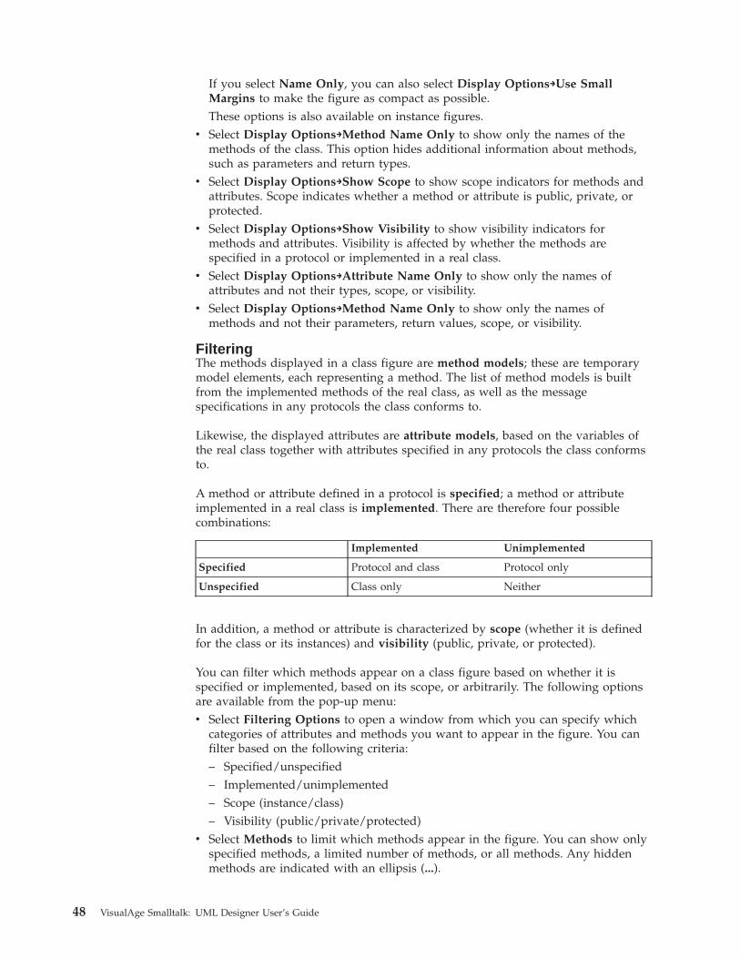
If you select Name Only, you can also select Display Options→Use SmallMargins to make the figure as compact as possible.These options is also available on instance figures.
v Select Display Options→Method Name Only to show only the names of themethods of the class. This option hides additional information about methods,such as parameters and return types.
v Select Display Options→Show Scope to show scope indicators for methods andattributes. Scope indicates whether a method or attribute is public, private, orprotected.
v Select Display Options→Show Visibility to show visibility indicators formethods and attributes. Visibility is affected by whether the methods arespecified in a protocol or implemented in a real class.
v Select Display Options→Attribute Name Only to show only the names ofattributes and not their types, scope, or visibility.
v Select Display Options→Method Name Only to show only the names ofmethods and not their parameters, return values, scope, or visibility.
FilteringThe methods displayed in a class figure are method models; these are temporarymodel elements, each representing a method. The list of method models is builtfrom the implemented methods of the real class, as well as the messagespecifications in any protocols the class conforms to.
Likewise, the displayed attributes are attribute models, based on the variables ofthe real class together with attributes specified in any protocols the class conformsto.
A method or attribute defined in a protocol is specified; a method or attributeimplemented in a real class is implemented. There are therefore four possiblecombinations:
Implemented Unimplemented
Specified Protocol and class Protocol only
Unspecified Class only Neither
In addition, a method or attribute is characterized by scope (whether it is definedfor the class or its instances) and visibility (public, private, or protected).
You can filter which methods appear on a class figure based on whether it isspecified or implemented, based on its scope, or arbitrarily. The following optionsare available from the pop-up menu:v Select Filtering Options to open a window from which you can specify which
categories of attributes and methods you want to appear in the figure. You canfilter based on the following criteria:– Specified/unspecified– Implemented/unimplemented– Scope (instance/class)– Visibility (public/private/protected)
v Select Methods to limit which methods appear in the figure. You can show onlyspecified methods, a limited number of methods, or all methods. Any hiddenmethods are indicated with an ellipsis (...).
48 VisualAge Smalltalk: UML Designer User’s Guide
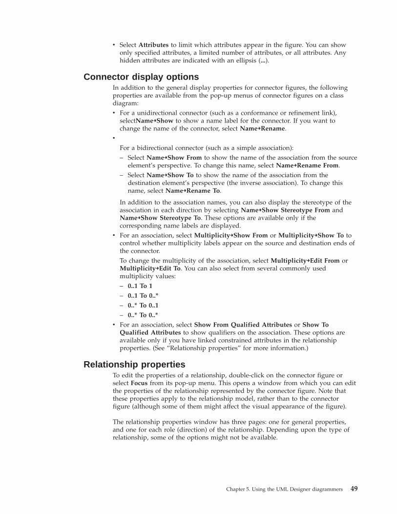
v Select Attributes to limit which attributes appear in the figure. You can showonly specified attributes, a limited number of attributes, or all attributes. Anyhidden attributes are indicated with an ellipsis (...).
Connector display optionsIn addition to the general display properties for connector figures, the followingproperties are available from the pop-up menus of connector figures on a classdiagram:v For a unidirectional connector (such as a conformance or refinement link),
selectName→Show to show a name label for the connector. If you want tochange the name of the connector, select Name→Rename.
v
For a bidirectional connector (such as a simple association):– Select Name→Show From to show the name of the association from the source
element’s perspective. To change this name, select Name→Rename From.– Select Name→Show To to show the name of the association from the
destination element’s perspective (the inverse association). To change thisname, select Name→Rename To.
In addition to the association names, you can also display the stereotype of theassociation in each direction by selecting Name→Show Stereotype From andName→Show Stereotype To. These options are available only if thecorresponding name labels are displayed.
v For an association, select Multiplicity→Show From or Multiplicity→Show To tocontrol whether multiplicity labels appear on the source and destination ends ofthe connector.To change the multiplicity of the association, select Multiplicity→Edit From orMultiplicity→Edit To. You can also select from several commonly usedmultiplicity values:– 0..1 To 1
– 0..1 To 0..*
– 0..* To 0..1
– 0..* To 0..*
v For an association, select Show From Qualified Attributes or Show ToQualified Attributes to show qualifiers on the association. These options areavailable only if you have linked constrained attributes in the relationshipproperties. (See “Relationship properties” for more information.)
Relationship propertiesTo edit the properties of a relationship, double-click on the connector figure orselect Focus from its pop-up menu. This opens a window from which you can editthe properties of the relationship represented by the connector figure. Note thatthese properties apply to the relationship model, rather than to the connectorfigure (although some of them might affect the visual appearance of the figure).
The relationship properties window has three pages: one for general properties,and one for each role (direction) of the relationship. Depending upon the type ofrelationship, some of the options might not be available.
Chapter 5. Using the UML Designer diagrammers 49
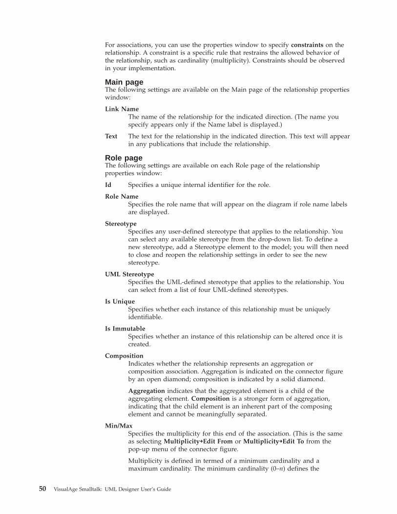
For associations, you can use the properties window to specify constraints on therelationship. A constraint is a specific rule that restrains the allowed behavior ofthe relationship, such as cardinality (multiplicity). Constraints should be observedin your implementation.
Main pageThe following settings are available on the Main page of the relationship propertieswindow:
Link NameThe name of the relationship for the indicated direction. (The name youspecify appears only if the Name label is displayed.)
Text The text for the relationship in the indicated direction. This text will appearin any publications that include the relationship.
Role pageThe following settings are available on each Role page of the relationshipproperties window:
Id Specifies a unique internal identifier for the role.
Role NameSpecifies the role name that will appear on the diagram if role name labelsare displayed.
StereotypeSpecifies any user-defined stereotype that applies to the relationship. Youcan select any available stereotype from the drop-down list. To define anew stereotype, add a Stereotype element to the model; you will then needto close and reopen the relationship settings in order to see the newstereotype.
UML StereotypeSpecifies the UML-defined stereotype that applies to the relationship. Youcan select from a list of four UML-defined stereotypes.
Is UniqueSpecifies whether each instance of this relationship must be uniquelyidentifiable.
Is ImmutableSpecifies whether an instance of this relationship can be altered once it iscreated.
CompositionIndicates whether the relationship represents an aggregation orcomposition association. Aggregation is indicated on the connector figureby an open diamond; composition is indicated by a solid diamond.
Aggregation indicates that the aggregated element is a child of theaggregating element. Composition is a stronger form of aggregation,indicating that the child element is an inherent part of the composingelement and cannot be meaningfully separated.
Min/MaxSpecifies the multiplicity for this end of the association. (This is the sameas selecting Multiplicity→Edit From or Multiplicity→Edit To from thepop-up menu of the connector figure.
Multiplicity is defined in termed of a minimum cardinality and amaximum cardinality. The minimum cardinality (0–n) defines the
50 VisualAge Smalltalk: UML Designer User’s Guide
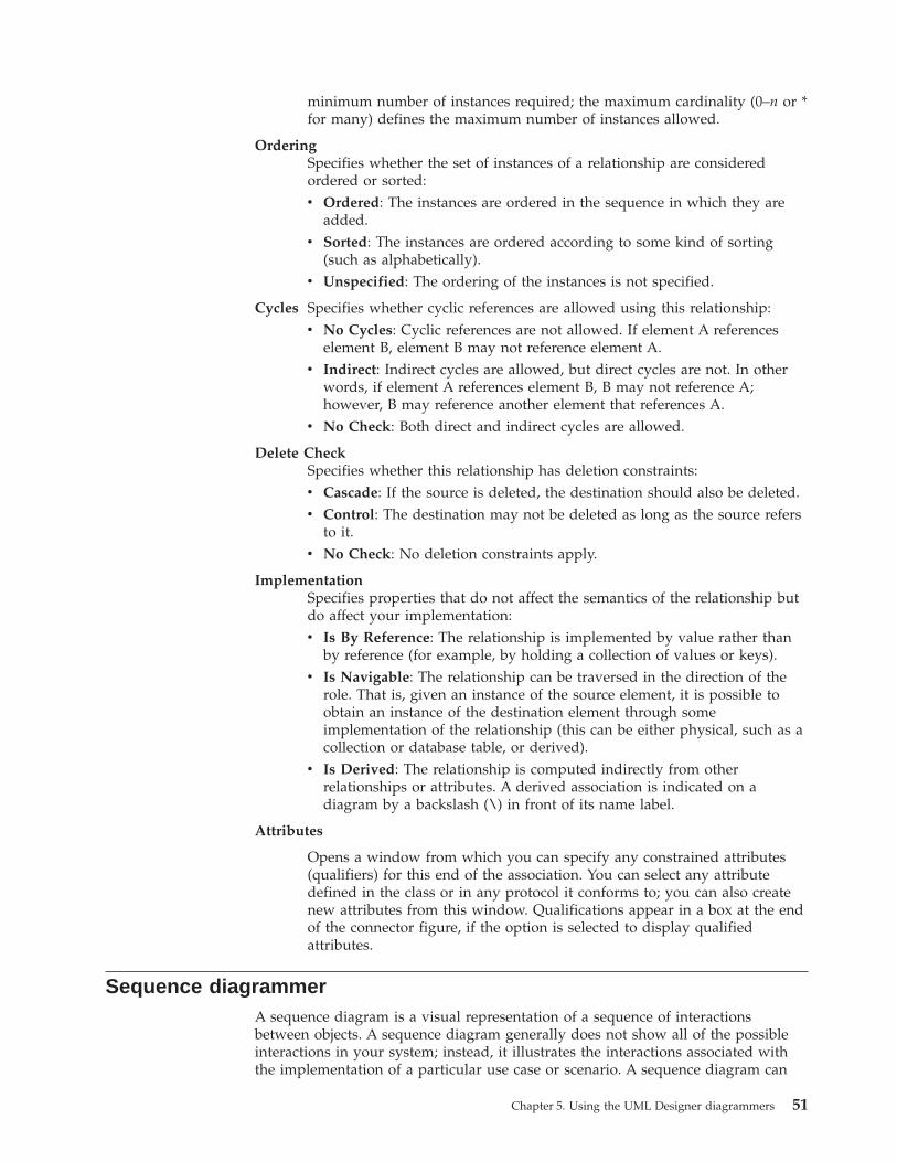
minimum number of instances required; the maximum cardinality (0–n or *for many) defines the maximum number of instances allowed.
OrderingSpecifies whether the set of instances of a relationship are consideredordered or sorted:v Ordered: The instances are ordered in the sequence in which they are
added.v Sorted: The instances are ordered according to some kind of sorting
(such as alphabetically).v Unspecified: The ordering of the instances is not specified.
Cycles Specifies whether cyclic references are allowed using this relationship:v No Cycles: Cyclic references are not allowed. If element A references
element B, element B may not reference element A.v Indirect: Indirect cycles are allowed, but direct cycles are not. In other
words, if element A references element B, B may not reference A;however, B may reference another element that references A.
v No Check: Both direct and indirect cycles are allowed.
Delete CheckSpecifies whether this relationship has deletion constraints:v Cascade: If the source is deleted, the destination should also be deleted.v Control: The destination may not be deleted as long as the source refers
to it.v No Check: No deletion constraints apply.
ImplementationSpecifies properties that do not affect the semantics of the relationship butdo affect your implementation:v Is By Reference: The relationship is implemented by value rather than
by reference (for example, by holding a collection of values or keys).v Is Navigable: The relationship can be traversed in the direction of the
role. That is, given an instance of the source element, it is possible toobtain an instance of the destination element through someimplementation of the relationship (this can be either physical, such as acollection or database table, or derived).
v Is Derived: The relationship is computed indirectly from otherrelationships or attributes. A derived association is indicated on adiagram by a backslash (\) in front of its name label.
Attributes
Opens a window from which you can specify any constrained attributes(qualifiers) for this end of the association. You can select any attributedefined in the class or in any protocol it conforms to; you can also createnew attributes from this window. Qualifications appear in a box at the endof the connector figure, if the option is selected to display qualifiedattributes.
Sequence diagrammerA sequence diagram is a visual representation of a sequence of interactionsbetween objects. A sequence diagram generally does not show all of the possibleinteractions in your system; instead, it illustrates the interactions associated withthe implementation of a particular use case or scenario. A sequence diagram can
Chapter 5. Using the UML Designer diagrammers 51
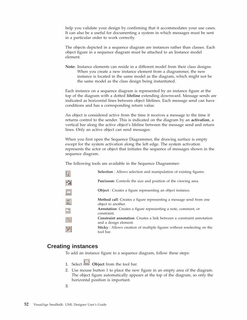
help you validate your design by confirming that it accommodates your use cases.It can also be a useful for documenting a system in which messages must be sentin a particular order to work correctly.
The objects depicted in a sequence diagram are instances rather than classes. Eachobject figure in a sequence diagram must be attached to an Instance modelelement.
Note: Instance elements can reside in a different model from their class designs.When you create a new instance element from a diagrammer, the newinstance is located in the same model as the diagram, which might not bethe same model as the class design being instantiated.
Each instance on a sequence diagram is represented by an instance figure at thetop of the diagram with a dotted lifeline extending downward. Message sends areindicated as horizontal lines between object lifelines. Each message send can haveconditions and has a corresponding return value.
An object is considered active from the time it receives a message to the time itreturns control to the sender. This is indicated on the diagram by an activation, avertical bar along the active object’s lifeline between the message send and returnlines. Only an active object can send messages.
When you first open the Sequence Diagrammer, the drawing surface is emptyexcept for the system activation along the left edge. The system activationrepresents the actor or object that initiates the sequence of messages shown in thesequence diagram.
The following tools are available in the Sequence Diagrammer:
Selection : Allows selection and manipulation of existing figures.
Pan/zoom: Controls the size and position of the viewing area.
Object : Creates a figure representing an object instance.
Method call: Creates a figure representing a message send from oneobject to another.Annotation: Creates a figure representing a note, comment, orconstraint.Constraint annotation: Creates a link between a constraint annotationand a design element.Sticky : Allows creation of multiple figures without reselecting on thetool bar.
Creating instancesTo add an instance figure to a sequence diagram, follow these steps:
1. Select Object from the tool bar.2. Use mouse button 1 to place the new figure in an empty area of the diagram.
The object figure automatically appears at the top of the diagram, so only thehorizontal position is important.
3.
52 VisualAge Smalltalk: UML Designer User’s Guide
Select Attach from the pop-up menu of the new object figure. A windowappears listing the available class designs.
4. Select the class of the object. and then select OK.
It is important to remember that objects in a sequence diagram are instances, notclasses. Therefore, when you select a class design to attach, UML Designerautomatically creates a new anonymous instance of the selected class and attachesthe figure to the new instance.
If you want to use a named instance rather than an anonymous instance, deselectIs Anonymous on the instance figure’s pop-up menu. You can then select Renameto change the name of the instance. (If you rename an anonymous instance, IsAnonymous is automatically deselected.
Creating method callsTo create a method call from one object to another, follow these steps:
1. Select Method call from the tool bar.2. For a call to an instance method, click mouse button 1 on the sender’s lifeline
within an activation.For a call to a class method, hold down the Alt key and click mouse button 1on the sender’s lifeline within an activation.
3. Click mouse button 1 on the receiver’s lifeline.
Note: For a call to self, click mouse button 1 on the same object’s lifeline forboth sender and receiver.
4. In the dialog that appears, specify the message you want to send:v In the Classes list, select the class that defines the method you want to call.
The list includes the class of the receiver as well as any classes it inheritsfrom.
Note: The list might include some candidate class designs, indicated by aplus sign (+). These class designs do not yet exist in the visiblemodels, but it will be created automatically if you select one of theirmethods. This happens if the real Smalltalk class of the selected objectinherits from ancestors which do not yet have class designs.
v In the Protocols list, select the protocol that specifies the method you want tocall. The list includes all protocols to which the selected class conforms.(Select <unspecified> if the method you want to call is not specified in aprotocol.)
v In the Messages list, select the message you want to send.5. Select OK. The new method call and its return appear as a method call figure.
In addition, the receiver’s lifeline now shows activation between the messagesend and return.
Moving and resizing method call figuresAfter you create a method call figure, you can then move it and resize theactivation to make room for other method calls.
To move a method call figure, select the activation and then drag it up or downwith mouse button 1. This moves the entire method call, including the activationand return call.
Chapter 5. Using the UML Designer diagrammers 53
To resize an activation, select the activation and then drag its bottom selectionhandle. This changes the amount of space between the method send and thereturn; you can do this to make room for more method calls.
Conditions and iterationA method call can have a condition, an annotation (written in natural language orpseudocode) that limits the conditions under which the message is sent.
To add or change the condition of a method call, select the message send figure(the arrow going from sender to receiver) and then select Edit Condition from thepop-up menu. Type the text of the condition (for example, x>0) and press Enter.
Iteration indicates that the message is sent multiple times to multiple receivers (forexample, iterating over a collection). To indicate iteration, select the message sendfigure and then select Is Iterated from the pop-up menu. An asterisk (*) appearsbeside the message send label to indicate iteration.
54 VisualAge Smalltalk: UML Designer User’s Guide
Chapter 6. Configuration management and version control
UML Designer design artifacts such as actors, use cases, and diagrams are storedin the VisualAge repository, which provides versioning and managementcapabilities. You can use the normal VisualAge (ENVY) team programmingcapabilities for library management tasks such as importing, exporting, andreplication.
As with Smalltalk code, the library maintains a fine-grained edition history ofindividual elements, allowing recovery of previous versions and configurations, aswell as identification of differences between editions. Version reconciliation issimilar to that used for Smalltalk code; however, UML Designer provides two newbrowsers that are specifically designed to help with managing editions of yourmodels.
This section describes the special considerations that apply to team developmentusing UML Designer.
Editions and versionsVersion control of models is similar to version control of Smalltalk code, but withsome differences to accommodate the extra subcomponents of the UML Designermetamodel. Generally speaking, you can think of a model as an application with asingle class representing the model; in fact, a model is stored as an ENVYapplication, with model elements stored within private storage classes.
For version control purposes, the elements in the model behave somewhatsimilarly to the methods of a class, in that they are editioned and releasedautomatically when you save changes. Unlike methods, though, some modelelements can also have child elements. For example, a protocol contains messagespecifications, which in turn contain parameters. To see the parent-childrelationships among elements, use the Contents filter in the Relationships Browser.
In order to make changes, you must have an open edition of the model. Each timeyou save changes to a model element, a new edition is created for that element,and the parent element points to the new edition. A model (like a class) isversioned as a whole. Normally, only one user owns a model and its open editions,but different users can have different editions open.
Each edition of a model or element points to the released edition of each element itcontains. An element is automatically released to its parent when it is created,loaded, or changed. You can also use the UML Designer Editions Browser tomanually release a different edition.
Browsing and loadingTo load a model that is not currently in your image, select Available from theSource menu of the Relationships Browser (or from the pop-up menu in the list ofmodels). This option opens a standard ENVY applications browser from which youcan choose the application containing the model you want.
To load a different edition of a model that you already have loaded, do one of thefollowing in the Relationships Browser:
© Copyright IBM Corp. 1997, 2000 55
v To use the standard ENVY browsers, select Application→Browse Editions fromthe Source menu, or from the pop-up menu in the list of models. This opens abrowser from which you can select the edition you want to load. This method isusually fastest, because it loads the entire application at once rather than oneelement at a time.
v Select Editions from the Source menu, or from the pop-up menu in the list ofmodels. This option opens a UML Designer Editions Browser from which youcan select the edition you want to load. This method shows more detail than thestandard ENVY browser, so it can be useful if you’re not sure which edition youwant.
Note: Any time you load a model using standard ENVY browsers (rather than theUML Designer Editions Browser), you must manually refresh any openUML Designer browsers in order to see the newly loaded model. There aretwo ways to do this:v To refresh a single browser, select Refresh Browser from the File menu of
the browser you want to refresh.v To close all open browsers, select Reset All Browsers from the UML
Designer menu of the Transcript window. You can then reopen thebrowsers you need.
Loading elementsLoading an edition of an element also loads the released editions of its children.You can also manually load other editions of the elements. You can do this ineither of two ways:v In the Relationships Browser, select a loaded element and then select Editions
from the pop-up menu. This opens a UML Designer Editions Browser fromwhich you can select the edition you want to load.
v In the Relationships Browser, select a relationship (such as Requirements) andthen select Available from the pop-up menu. This opens a browser from whichyou can select the element and edition you want to load.
Note: You should always use the UML Designer Editions Browser or HierarchicalChange Browser (rather than the standard ENVY browsers) to browse andload editions of model elements. These browsers are designed to displaymodel elements. See “Using the UML Designer browsers” on page 57 formore information.
Crash recoveryTo recover from a crash, restart your image. If you have made changes to yourmodel more recently than the last time you saved your image, load the latestedition of the model application. Loading the model automatically loads thereleased child elements as well.
Composite objectsCertain types of elements, called composite objects, are stored within their parents,limiting the ways in which they can be browsed and loaded. The followingelements, all part of message specifications, are composite objects:v Parameterv Parameter textv Return valuev Return value textv Attribute
56 VisualAge Smalltalk: UML Designer User’s Guide
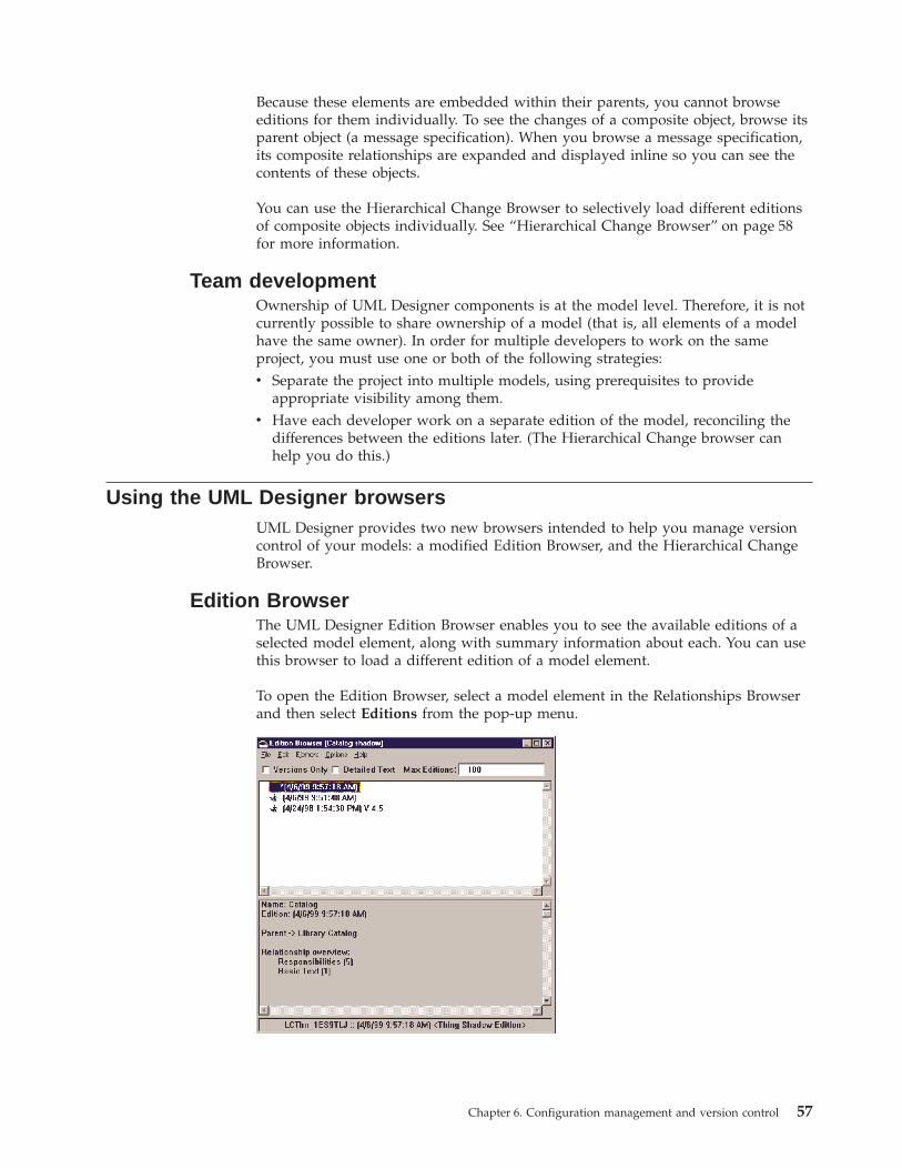
Because these elements are embedded within their parents, you cannot browseeditions for them individually. To see the changes of a composite object, browse itsparent object (a message specification). When you browse a message specification,its composite relationships are expanded and displayed inline so you can see thecontents of these objects.
You can use the Hierarchical Change Browser to selectively load different editionsof composite objects individually. See “Hierarchical Change Browser” on page 58for more information.
Team developmentOwnership of UML Designer components is at the model level. Therefore, it is notcurrently possible to share ownership of a model (that is, all elements of a modelhave the same owner). In order for multiple developers to work on the sameproject, you must use one or both of the following strategies:v Separate the project into multiple models, using prerequisites to provide
appropriate visibility among them.v Have each developer work on a separate edition of the model, reconciling the
differences between the editions later. (The Hierarchical Change browser canhelp you do this.)
Using the UML Designer browsersUML Designer provides two new browsers intended to help you manage versioncontrol of your models: a modified Edition Browser, and the Hierarchical ChangeBrowser.
Edition BrowserThe UML Designer Edition Browser enables you to see the available editions of aselected model element, along with summary information about each. You can usethis browser to load a different edition of a model element.
To open the Edition Browser, select a model element in the Relationships Browserand then select Editions from the pop-up menu.
Chapter 6. Configuration management and version control 57
The top pane of the Editions Browser shows a list of the available editions andversions of the selected model element. An asterisk (*) indicates the currentlyloaded edition.
The bottom pane of the Editions Browser shows information about the editioncurrently selected in the top pane. This information includes:v Namev Parentv Links to other elementsv Contents
Browser optionsYou can use several browser options to control the information that appears in theEdition Browser.v Select Versions Only to include only named versions (no editions) in the
browser.v Use Detailed Text to control how much information the browser shows about
the element’s links to other elements:– If Detailed Text is selected, the browser lists each link separately, including
the type of relationship and the name of the linked element.– If Detailed Text is not selected, the browser lists only the number of links of
each type.v Use Max Editions to control how many editions the browser should show
(starting with the most recent and working backward). For an element with alarge number of older editions, this option can help to speed up library access,particularly if Detailed Text is selected.
Hierarchical Change BrowserThe Hierarchical Change Browser is a specialized UML Designer browser you canuse to compare and reconcile the differences between editions of an element. Thisbrowser is particularly useful in a situation where different developers have beenworking on different editions of the same model, and you now want to merge theeditions together into a single consistent edition.
To open the Hierarchical Change Browser, select an element in the RelationshipsBrowser and then do one of the following:v Select Browse Changes→Previous Edition to compare the currently loaded
edition with the previous edition.v Select Browse Changes→Another Edition to compare the currently loaded
edition with any other edition. You will be prompted to select the edition tocompare to.
58 VisualAge Smalltalk: UML Designer User’s Guide
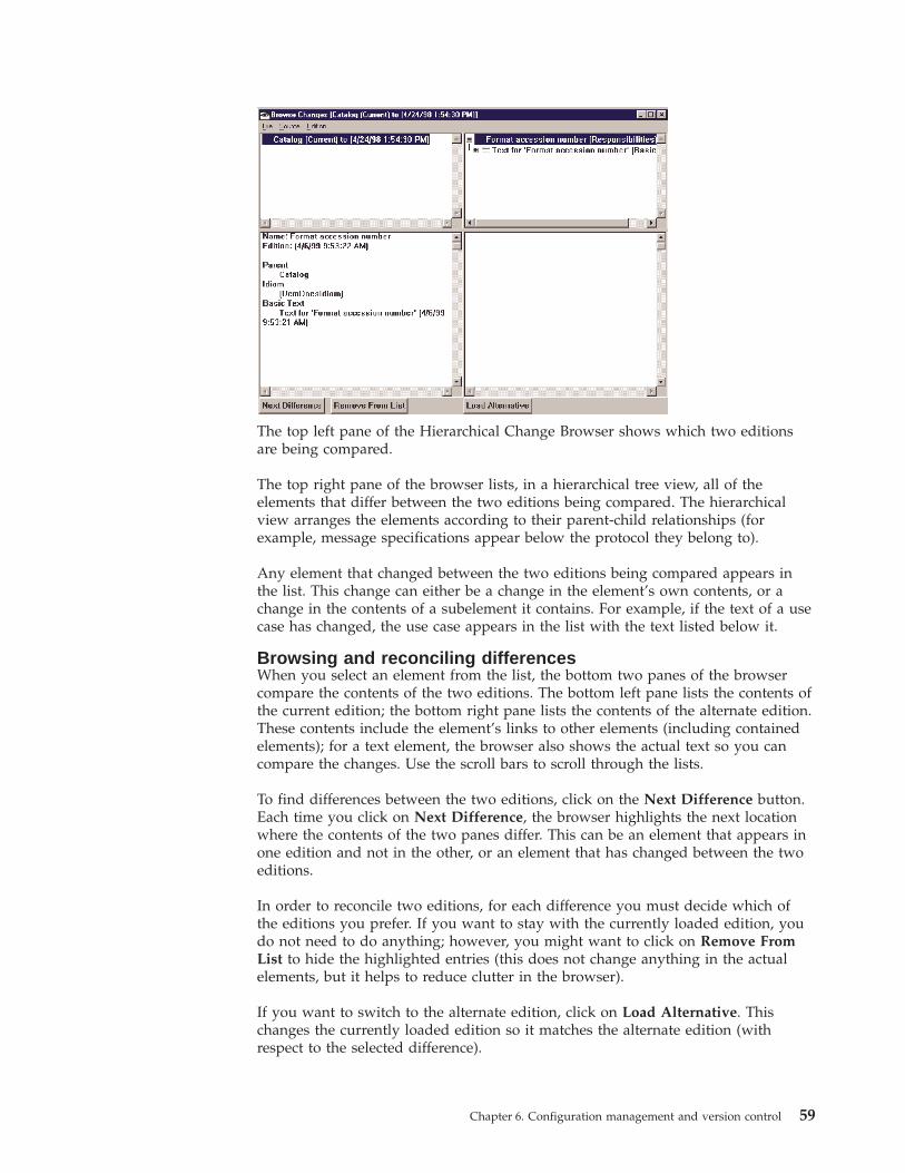
The top left pane of the Hierarchical Change Browser shows which two editionsare being compared.
The top right pane of the browser lists, in a hierarchical tree view, all of theelements that differ between the two editions being compared. The hierarchicalview arranges the elements according to their parent-child relationships (forexample, message specifications appear below the protocol they belong to).
Any element that changed between the two editions being compared appears inthe list. This change can either be a change in the element’s own contents, or achange in the contents of a subelement it contains. For example, if the text of a usecase has changed, the use case appears in the list with the text listed below it.
Browsing and reconciling differencesWhen you select an element from the list, the bottom two panes of the browsercompare the contents of the two editions. The bottom left pane lists the contents ofthe current edition; the bottom right pane lists the contents of the alternate edition.These contents include the element’s links to other elements (including containedelements); for a text element, the browser also shows the actual text so you cancompare the changes. Use the scroll bars to scroll through the lists.
To find differences between the two editions, click on the Next Difference button.Each time you click on Next Difference, the browser highlights the next locationwhere the contents of the two panes differ. This can be an element that appears inone edition and not in the other, or an element that has changed between the twoeditions.
In order to reconcile two editions, for each difference you must decide which ofthe editions you prefer. If you want to stay with the currently loaded edition, youdo not need to do anything; however, you might want to click on Remove FromList to hide the highlighted entries (this does not change anything in the actualelements, but it helps to reduce clutter in the browser).
If you want to switch to the alternate edition, click on Load Alternative. Thischanges the currently loaded edition so it matches the alternate edition (withrespect to the selected difference).
Chapter 6. Configuration management and version control 59

60 VisualAge Smalltalk: UML Designer User’s Guide
Chapter 7. Importing and exporting models
Object Extender import/exportThe VisualAge Object Extender feature provides tools you can use to model, map,and generate classes for persistent application objects. UML Designer can importmodel information from, or export it to, Object Extender models. (Similarly, ObjectExtender can import from or export to UML Designer models; see the VisualAgeSmalltalk ObjectExtender User’s Guide and Reference for more information.)
When you import model information from Object Extender, UML Designerconverts each selected model class into a protocol and a conforming class design,using the same name as the Object Extender model class. If there is an associatedSmalltalk class generated from Object Extender, that class will also be linked as thereal implementing class of the class design.
For each attribute in the model class, UML Designer creates an attribute in thegenerated protocol. If the attribute is marked as a required value in the modelclass, UML Designer uses the Key Attribute idiom for the generated attribute.
In the generated class designs and protocols, UML Designer maintains anyinheritance relationships among the Object Extender model classes. If the modelclass has no parent model class, the generated UML Designer class design andprotocol are children of the Object Extender default persistent class root(configured in the Object Extender Model Browser’s generation options). TheObject Extender Base model, which contains class designs and protocols for themost important Object Extender root classes, is automatically set as a prerequisitefor any model containing elements imported from Object Extender.
UML Designer also preserves any associations among the imported model classes,provided both source and target of each association are being imported.
Importing model elements from Object ExtenderTo import model elements from Object Extender into a UML Designer model,follow these steps:1. In the Relationships Browser, select the model you want to contain the
imported elements. (Create a new model if necessary.)2. Select Transforms→Import From Object Extender from the pop-up menu.
A prompter appears listing the available Object Extender models.3. Select the Object Extender model that contains the model classes you want to
import. Then select OK.4. When prompted, select the Object Extender model classes you want to import.
(Remember that if you want to preserve associations between classes, you mustimport both the source and destination classes). Then select OK.
After the import operation completes, the target UML Designer model contains aclass design and a protocol for each selected Object Extender model class. You cannow use these elements in your model as with any other UML Designer elements.
Exporting model elements to Object ExtenderTo export class designs to Object Extender, follow these steps:
© Copyright IBM Corp. 1997, 2000 61
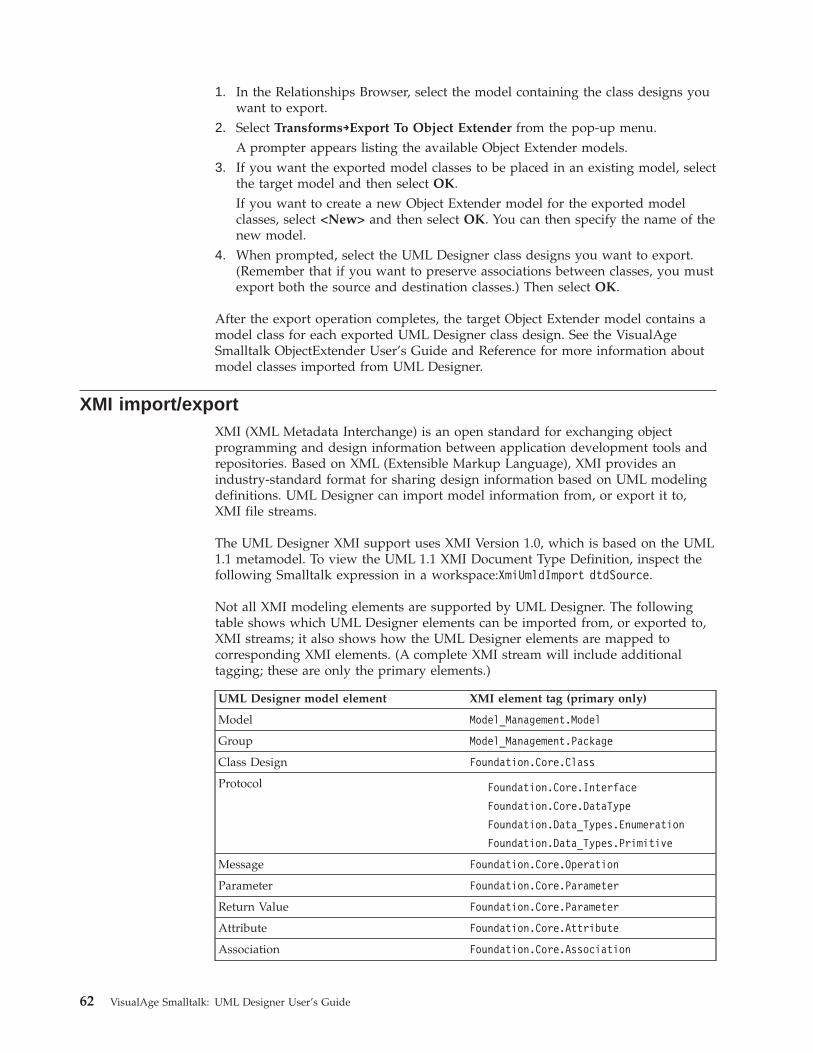
1. In the Relationships Browser, select the model containing the class designs youwant to export.
2. Select Transforms→Export To Object Extender from the pop-up menu.A prompter appears listing the available Object Extender models.
3. If you want the exported model classes to be placed in an existing model, selectthe target model and then select OK.If you want to create a new Object Extender model for the exported modelclasses, select <New> and then select OK. You can then specify the name of thenew model.
4. When prompted, select the UML Designer class designs you want to export.(Remember that if you want to preserve associations between classes, you mustexport both the source and destination classes.) Then select OK.
After the export operation completes, the target Object Extender model contains amodel class for each exported UML Designer class design. See the VisualAgeSmalltalk ObjectExtender User’s Guide and Reference for more information aboutmodel classes imported from UML Designer.
XMI import/exportXMI (XML Metadata Interchange) is an open standard for exchanging objectprogramming and design information between application development tools andrepositories. Based on XML (Extensible Markup Language), XMI provides anindustry-standard format for sharing design information based on UML modelingdefinitions. UML Designer can import model information from, or export it to,XMI file streams.
The UML Designer XMI support uses XMI Version 1.0, which is based on the UML1.1 metamodel. To view the UML 1.1 XMI Document Type Definition, inspect thefollowing Smalltalk expression in a workspace:XmiUmldImport dtdSource.
Not all XMI modeling elements are supported by UML Designer. The followingtable shows which UML Designer elements can be imported from, or exported to,XMI streams; it also shows how the UML Designer elements are mapped tocorresponding XMI elements. (A complete XMI stream will include additionaltagging; these are only the primary elements.)
UML Designer model element XMI element tag (primary only)
Model Model_Management.Model
Group Model_Management.Package
Class Design Foundation.Core.Class
Protocol Foundation.Core.Interface
Foundation.Core.DataType
Foundation.Data_Types.Enumeration
Foundation.Data_Types.Primitive
Message Foundation.Core.Operation
Parameter Foundation.Core.Parameter
Return Value Foundation.Core.Parameter
Attribute Foundation.Core.Attribute
Association Foundation.Core.Association
62 VisualAge Smalltalk: UML Designer User’s Guide
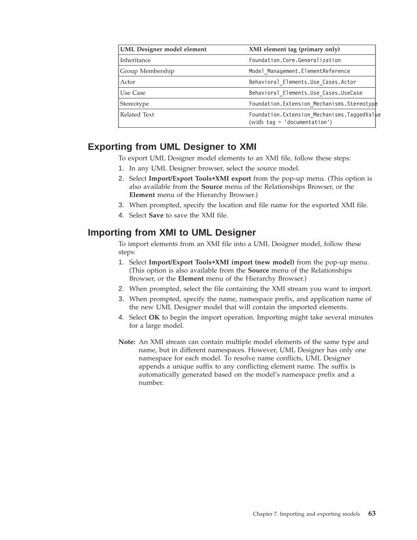
UML Designer model element XMI element tag (primary only)
Inheritance Foundation.Core.Generalization
Group Membership Model_Management.ElementReference
Actor Behavioral_Elements.Use_Cases.Actor
Use Case Behavioral_Elements.Use_Cases.UseCase
Stereotype Foundation.Extension_Mechanisms.Stereotype
Related Text Foundation.Extension_Mechanisms.TaggedValue(with tag = 'documentation')
Exporting from UML Designer to XMITo export UML Designer model elements to an XMI file, follow these steps:1. In any UML Designer browser, select the source model.2. Select Import/Export Tools→XMI export from the pop-up menu. (This option is
also available from the Source menu of the Relationships Browser, or theElement menu of the Hierarchy Browser.)
3. When prompted, specify the location and file name for the exported XMI file.4. Select Save to save the XMI file.
Importing from XMI to UML DesignerTo import elements from an XMI file into a UML Designer model, follow thesesteps:1. Select Import/Export Tools→XMI import (new model) from the pop-up menu.
(This option is also available from the Source menu of the RelationshipsBrowser, or the Element menu of the Hierarchy Browser.)
2. When prompted, select the file containing the XMI stream you want to import.3. When prompted, specify the name, namespace prefix, and application name of
the new UML Designer model that will contain the imported elements.4. Select OK to begin the import operation. Importing might take several minutes
for a large model.
Note: An XMI stream can contain multiple model elements of the same type andname, but in different namespaces. However, UML Designer has only onenamespace for each model. To resolve name conflicts, UML Designerappends a unique suffix to any conflicting element name. The suffix isautomatically generated based on the model’s namespace prefix and anumber.
Chapter 7. Importing and exporting models 63

64 VisualAge Smalltalk: UML Designer User’s Guide

Part 3. Building models with UML Designer
© Copyright IBM Corp. 1997, 2000 65

66 VisualAge Smalltalk: UML Designer User’s Guide
Chapter 8. Capturing requirements
The first step in a “forward” development process is to capture the requirementsfor the system being developed. (For more information about requirements, see“Requirement” on page 8. For our example, we want to build a library catalogsystem. Our users describe the system they want as follows:
The system must maintain a catalog of the available books in the library. Books must beseparately indexed by title, author, and Dewey Decimal System number. The system mustsupport registering newly acquired books and catalog queries to find existing books.
Based on this description (and perhaps conversations with users), we can thenbegin to derive a list of discrete requirements for the system, and we can use UMLDesigner to capture them.
Starting a new modelTo start working in UML Designer, select Relationships Browser from the UMLDesigner menu in the Transcript window. The Relationships Browser opens.
The Relationships Browser shows the available models, the design elements ineach model, and the relationships that exist among them. From here, you cancreate new design elements, browse and modify their relationships, and launch theother UML Designer browsers and editors. (For more information about theRelationships Browser, see “The Relationships Browser” on page 27.)
When you first install UML Designer, three models are automatically included:v Kernel Model includes design elements for some implementation-independent
common data types.v Kernel Model—Java Examples includes design elements for Java data types.v Kernel Model—Smalltalk Examples includes design elements for Smalltalk data
types.
Since you’re likely to need some of the basic data types in any system you design,UML Designer, by default, makes the Kernel Model and Kernel Model—SmalltalkExamples prerequisites for any models you create. (If you want to use Java datatypes, you will need to manually add Kernel Model—Java Examples as aprerequisite.) This means that the basic Smalltalk classes in the Kernel models areautomatically visible from any other model.
To begin modeling a new system, you must first create a new model in theRelationships Browser:1. Select Create Model from the Source menu, or from the pop-up menu in the
leftmost pane in the Relationships Browser.2. When prompted, specify the following information about the new model:v The specification name of the model. This can be any name you want to use
to identify the model. Our example will be a system to catalog library books,so type Library Catalog.
v The namespace prefix for the model. This is an arbitrary string that will beused as a prefix to uniquely identify the model and its elements in the
© Copyright IBM Corp. 1997, 2000 67
Smalltalk repository. You can accept the default value for this prefix, or youcan add your initials or some other unique identifier if you share the samerepository with other users.
v The Smalltalk application name for the model. This is the name that will beused for the application containing the model elements. You will notnormally need to access this application directly, so in most cases you canaccept the default application name, which is the model name appended tothe namespace prefix.
3. Select OK. The new model appears in the list in the Relationships Browser.
Adding Requirement elementsBy looking at the above description from our users, we might derive the followingindividual requirements for the system:v Keep a catalog of available booksv Index books by title, author, and Dewey numberv Support catalog queries
To add these requirements to the model, follow these steps:1. Select Library Catalog from the list of models in the leftmost pane of the
Relationships Browser. The middle pane shows a list of possible relationshipsto model elements the model might contain.
2. In the middle pane, select Requirements. The rightmost pane shows a list ofrequirements already defined for the model; since we haven’t created any yet,the list is empty.
3. Select New from the Relationships menu, or from the pop-up menu for theselected relationship.
4. When prompted for the requirement name, type Keep a catalog of available books.
5. Select OK. The new requirement appears in the list.6. Repeat the same process to add the other two requirements listed above.
After you have added all three requirements to the list, you can provide additionaldescriptive text for each requirement. To do this, select the requirement you wantto describe, and then use the bottom text pane of the Relationships Browser to typethe requirement text. This text pane can contain any kind of description you wantto capture for the requirement; it can also contain hypertext links to other modelelements. Our example’s requirements are fairly straightforward and probably donot need much more explanation at this stage. Instead, let’s move on to use cases.
68 VisualAge Smalltalk: UML Designer User’s Guide
Chapter 9. Writing and analyzing use cases
Once you have captured your initial requirements, you can write use cases for thesystem, using Use Case elements to record them. For more information about usecases, see “Use case” on page 8.
Adding Use Case elementsBased on the requirements for the library catalog system, we can identify three usecases, each describing a particular user task:v Adding a new book to the catalogv Removing a book from the catalogv Querying the catalog to find a book
To add these use cases to the Library Catalog model, follow these steps:1. Select Use Cases in the middle pane of the Relationships Browser.2. Select New from the Relationships menu, or from the pop-up menu in the
middle pane.3. Type Adding a new book to the catalog.
4. Select OK. The new use case appears in the list in the rightmost pane.5. Repeat the same procedure to add the other two use cases listed above.
A use case requires a carefully written description, rather than just a brief title. Wemust now use the hypertext pane (at the bottom of the Relationships Browser) toadd detail to each use case. To edit the text of a use case, select the use case fromthe list and type the text in the hypertext pane. You can use the hypertext pane’spop-up menu to save the text, just as in any Smalltalk browser.
Add the following text to the first use case, Adding a new book to the catalog:
A new book arrives at the library, and a librarian creates a new catalog entry with thebook’s author, title, and Dewey number. The catalog entry is then assigned a serial numberand registered in the catalog. The catalog uses the book’s Dewey number to print abookplate and spine label for the book.
When you have finished, save the text by selecting Save from the pop-up menu orpressing Ctrl+S.
Optionally, you can add descriptive text for the other use cases you created. Thesearen’t necessary for the rest of the example, because we will focus on the Adding anew book use case.
Making links between elementsUse cases can be related to requirements. They elaborate upon what therequirements entail, and in some cases they can uncover additional requirements.Each use case satisfies one or more requirements; if a use case does not satisfy anyrequirement, either a new requirement should be added, or the use case is outsidethe scope of the system and should be dropped.
© Copyright IBM Corp. 1997, 2000 69
In UML Designer, you can create links between model elements in order to showthis “satisfies” relationship, as well as other relationships. Such links contribute totraceability. Traceability is the ability to move between elements at different levelsof abstraction. For example, you can track which use cases satisfy eachrequirement, or which requirements are satisfied by each use case. This traceabilityhelps to clarify why the elements in the model are what they are and how theybecame that way.
Adding a ″satisfies ″ linkTo add a “satisfies” link between a use case and a requirement, follow these steps:1. Select Use Cases in the middle pane of the Relationships Browser.2. Select Adding a new book to the catalog from the list.3. Select Link→Satisfied Requirements from the pop-up menu of the use case. A
window appears listing the available requirements.4. Select Keep a catalog of available books from the list.5. Select >> to add the selected requirement to the list of linked requirements.6. Select OK.
To see the effect of this link, double-click on Adding a new book to the catalog inorder to open a browser on that requirement. In the middle pane of the browser,select the Satisfied Requirements relationship. You should see a list including Keepa catalog of available books.
Optionally, you can add “satisfies” links from the other use cases you created.
Analyzing a use caseOnce you have a use case description, you can analyze the use case to beginidentifying some of the elements that will play a part in the system. One way tostart is to look for all of the nouns in the use case description to see which onesseem to refer to important elements of the system. Each time you find animportant idea in the use case, you can classify it as one of the following designelements (see “Requirements model elements” on page 8 for more information onthese elements):v An actor outside the system.v A thing within the system (also called a domain object).v A concept that needs to be recorded, but might not be a thing.v Another related use case. There are two kinds of relationships that use cases can
have with one another:– A use case can use another use case, represented by a simple “associated
with” relationship.– A use case can extend another use case, represented by an “extends”
relationship.
Now, let’s take a look at the text of the Adding a book use case to see what otherdesign elements it refers to.
70 VisualAge Smalltalk: UML Designer User’s Guide
Identifying actorsThe action of the Adding a book use case is initiated by a librarian, a human user.This is a person who actually enters the information for a new book and initiatesthe cataloging operation. Because the librarian exists outside the system andprovides the stimulus setting the use case in motion, the librarian is an actor. Wecan now create an Actor element in the Library Catalog model to represent thelibrarian.
Adding an Actor elementTo create a new actor, follow these steps:1. Select Actors in the middle pane of the Relationships Browser.2. Select New from the Relationships menu, or from the pop-up menu of the
relationship.3. When prompted for the name of the actor, type Librarian.4. Select OK. The new actor appears in the list in the rightmost pane.
Adding a hypertext linkSince we have created an Actor element to represent the librarian, we can nowindicate the relationship between this actor and the use case in which itparticipates. One way to do this is with a hypertext link in the use casedescription.
To insert a hypertext link for the Librarian actor, follow these steps:1. Select Use Cases in the middle pane of the Relationships Browser.2. Select Adding a new book to the catalog from the list of use cases.3. In the text pane, select the word librarian in the use case description. (You can
do this with the keyboard, by swiping the mouse, or by double-clicking on theword.)
4. Select Insert Link→Reference from the pop-up menu of the text pane. Awindow appears showing the different kinds of objects you can link to.
5. In this case, the object we want to link to is an actor, so select Actor from thelist. A list of available actors appears; at this point, we have only created oneactor, Librarian, so no other choices appear.
6. Select Librarian and then select OK.7. A window now appears verifying the label for this actor you want to appear in
the text of the use case (the label of a link can be different from the name of thedestination element). If you wanted to change the wording of the reference tothe librarian in the use case description, you could change it here; for now,select OK to accept the default.
An actor icon appears beside the word librarian to indicate the existence of a linkto an actor in the model. You can follow this hypertext link by double-clicking onthe linked word. This opens a browser on the Librarian actor.
Chapter 9. Writing and analyzing use cases 71
Identifying things and responsibilitiesThe object model of an OO system usually has a strong correspondence to theactual real-world entities of the domain: for each domain entity (whether physicalor intangible), there is generally one or more corresponding implementationobjects. This “natural” model helps to make the system understandable, and it alsomeans that changes to the problem domain map well to changes in the software.
To choose the correct objects for the system, you need to identify the requiredbehavior of the objects. With UML Designer, you do this by creating things(domain objects) and assigning responsibilities to them.
In the Adding a new book use case, there are several terms that refer to entities thatexist within the system (unlike the librarian, who is outside the system):v libraryv catalog entryv catalog
These are candidates to become objects in the implemented system. We can nowcreate Thing elements in the Library Catalog model to represent each of these.
Adding (and linking to) a new Thing elementIn the actor example above, we manually created a new Actor element for Librarianand then separately created a hypertext link to it. This time, let’s let the system dosome of the work for us; we can simultaneously create a new element and ahypertext link to it. To do this, follow these steps:1. Select Use Cases in the middle pane of the Relationships Browser.2. Select Adding a new book to the catalog from the list of use cases.3. In the use case text, select the word library.4. Select Insert Link→Reference from the pop-up menu in the text pane. A
window appears listing the different kinds of objects you can link to.5. We want to link to a thing, so select Thing from the list. You can accept the
default name Library, which is derived from the selected text in the use case.6. Select New, indicating that we want to create a new element.7. Select OK to confirm the text label for the link.8. Repeat the same process for catalog entry and catalog.
For each hypertext link, a Thing icon appears along the linked text in the usecase description indicating the link to a Thing element. If you select Things in themiddle pane of the Relationships Browser, you should see Catalog, Catalog entry,and Library listed.
Identifying responsibilitiesThe next step is to identify the responsibilities of the domain objects. At this stage,it can also be helpful to use “computer-free” techniques such as CRC cards toidentify responsibilities, entering the results as new responsibility elements. (CRCcards—“Class-Responsibility-Collaboration” cards—are a technique developed byWard Cunningham and Kent Beck using index cards to represent candidate objectsin a system and elucidate their collaborations.)
To find responsibilities, go through the text of a use case and identify what thethings and actors must do. You can then assign each responsibility to the
72 VisualAge Smalltalk: UML Designer User’s Guide
appropriate thing or actor. In addition, each responsibility can be linked tocollaborating participants, the other things or actors that participate in theresponsibility.
Adding responsibility elementsConsider Catalog, which we have identified as a thing in the library catalogexample. Based on our use cases, Catalog (which we have identified as a thing)might have the following responsibilities:v Add catalog entryv Assign accession number to entryv Find entry by search criteriav Remove catalog entry
To add these responsibilities of Catalog to the model, follow these steps:1. Select Things in the middle pane of the Relationships Browser.2. Select Catalog from the list of things.3. Select New→Responsibility from the pop-up menu of Catalog. A window
appears prompting you for the details of the new responsibility.4. Type Add catalog entry and select OK.5. For Idiom, accept the default (Action). This responsibility describes something
Catalog does.Don’t worry about participants for now; we will deal with those shortly.
6. Repeat the same procedure for the other responsibilities listed above.
Similarly, you can create responsibilities for actors by following the same steps.Select the actor Librarian and add the following responsibilities:v Input new catalog entryv Classify book and assign Dewey numberv Query catalog using search criteriav Remove existing catalog entry
Note: Because Actor elements are not transformed into protocols, actorresponsibilities do not have idioms.
Using another idiomAll of the responsibilities we have added for Catalog have been simple “action”responsibilities. However, consider another Thing, Catalog Entry; it does not haveto do anything except keep track of its own attributes (author, title, and accessionnumber). We can define these as responsibilities using the Value idiom to give us ahead start on implementation later.
To add these responsibilities, follow these steps:1. In the Relationships Browser, select Catalog Entry from the list of things.2. Select New→Responsibility from the pop-up menu. A window appears
prompting you for the details of the new responsibility.3. For Idiom, select Value. This responsibility describes something Catalog Entry
keeps.4. In the Responsibility Namefield, type Author. (We phrase this responsibility as
a noun because it describes a value rather than an action.)5. For Max Cardinality, select 1.
Chapter 9. Writing and analyzing use cases 73
6. Optionally, we could specify a participant defining the type of the value beingkept. At this point, though, we aren’t really interested in how the author willbe represented, so accept the default and select OK.
7. Repeat the same process for two other responsibilities, Title and AccessionNumber.
Because we used the Value idiom for these responsibilities, UML Designer cangenerate appropriate sets of messages when we transform Catalog Entry into aprotocol. We’ll see how this works in “Chapter 11. Protocols” on page 81.
Linking to participantsIn addition to indicating the responsibilities of a thing or actor, you can alsoindicate which other things or actors are collaborating participants in eachresponsibility. To do this, you create a link from a defined responsibility to a thingor actor that participates. (You can also specify participants along with idioms asyou create a new responsibility.)
In our example, three of the responsibilities of Catalog also involve catalog entries:v Add catalog entryv Assign accession number to entryv Remove catalog entry
Each of these is a responsibility of Catalog, but each also involves another thing,Catalog entry. Therefore, you can create a link from each of these responsibilities tothe Catalog entry element to indicate that it participates. To do so, follow thesesteps:
1. Select Things in the middle pane of the Relationships Browser.2. Double-click on Catalog. A browser opens on the Catalog element.3. Select Responsibilities in the middle pane of the browser.4. Select Add catalog entry from the list of responsibilities.5. Select Link→Participants from the pop-up menu of the responsibility. A
window appears prompting you for the link destination.6. A participant can be either an actor or a thing. In this case, Catalog entry is a
thing, so select Thing from the Available Types list.7. Select Catalog entry.8. Select >> to add Catalog entry to the list of linked participants.9. Select OK.
10. Repeat the same process with Assign accession number to entry and Removecatalog entry, adding Catalog entry as a participant in each responsibility.
11. Close the browser.
Identifying conceptsIn addition to actors and things, there might be other important ideas described inthe use case that need to be documented. Going through the use case description,we can identify terms that need additional explanation. As you do this, it’simportant to decide on standard terminology, in order to be sure everyoneunderstands the requirements the same way. Careful definition of terms can helpto overcome the imprecision and ambiguity inherent in natural language.
As a general rule, each term should refer to only one concept, and each conceptshould be described by only one term. In addition, any domain-specific
74 VisualAge Smalltalk: UML Designer User’s Guide
terminology, or domain-specific usage of common terms, should be fully defined.We can use concept elements to capture this information.
Adding a Concept elementIn the Adding a new book use case, several phrases appear to be important conceptsthat should be documented. For example, Dewey number is domain-specificterminology that should be defined for the benefit of non-librarians. A descriptioncan also help us understand how we need to represent it in the system.
The Dewey number is an attribute of a catalog entry, so it’s probably not a thing inits own right; therefore, we’ll use a Concept element to define it. To do this, followthese steps:1. Select Use Cases in the middle pane of the Relationships Browser.2. Select Adding a new book in the list of use cases.3. Select the phrase Dewey number in the hypertext pane.4. Create a hypertext reference link from the phrase to a new Concept element.
(Use the same process you used to create the links above, but select Concept asthe kind of object to link to.)
5. In the text pane for the new Dewey number concept element, type a descriptionof a Dewey number:A Dewey number is a numerical classification identifying a book’s subject matter.
Another phrase that looks like a good candidate for a Concept element is serialnumber. Like the Dewey number, the serial number is an attribute of a catalogentry, so it is probably not a thing; however, it’s an important concept thatprobably should be recorded. But suppose that, in trying to define serial number,we find that our use case does not reflect correct terminology?
Revising description textAs you find out more about the problem domain, you will probably find that someparts of your use cases or requirements are vague or inaccurate or do not reflectthe correct terminology. UML Designer accommodates this situation; you canrename model elements and revise their contents while still preserving any linksbetween them. Furthermore, because all models are stored in the Smalltalkrepository, you can always return to a previous version.
For example, we might find out that librarians assign a new book an accessionnumber rather than a serial number. We now need to update our Adding a new bookuse case, replacing the phrase “serial number” with “accession number”. The newuse case description should read:
A new book arrives at the library, and a librarian creates a new catalog entry with thebook’s author, title, and Dewey number. The catalog entry is then assigned an accessionnumber and registered in the catalog. The catalog uses the book’s Dewey number to print abookplate and spine label for the book.
Edit the use case text to use the correct terminology and then save the new text.After you save it, select Text Editions from the pop-up menu in the hypertextpane. A browser opens showing all of the saved editions of the text of this usecase; if you change your mind, you can always reload an older edition.
Chapter 9. Writing and analyzing use cases 75

76 VisualAge Smalltalk: UML Designer User’s Guide
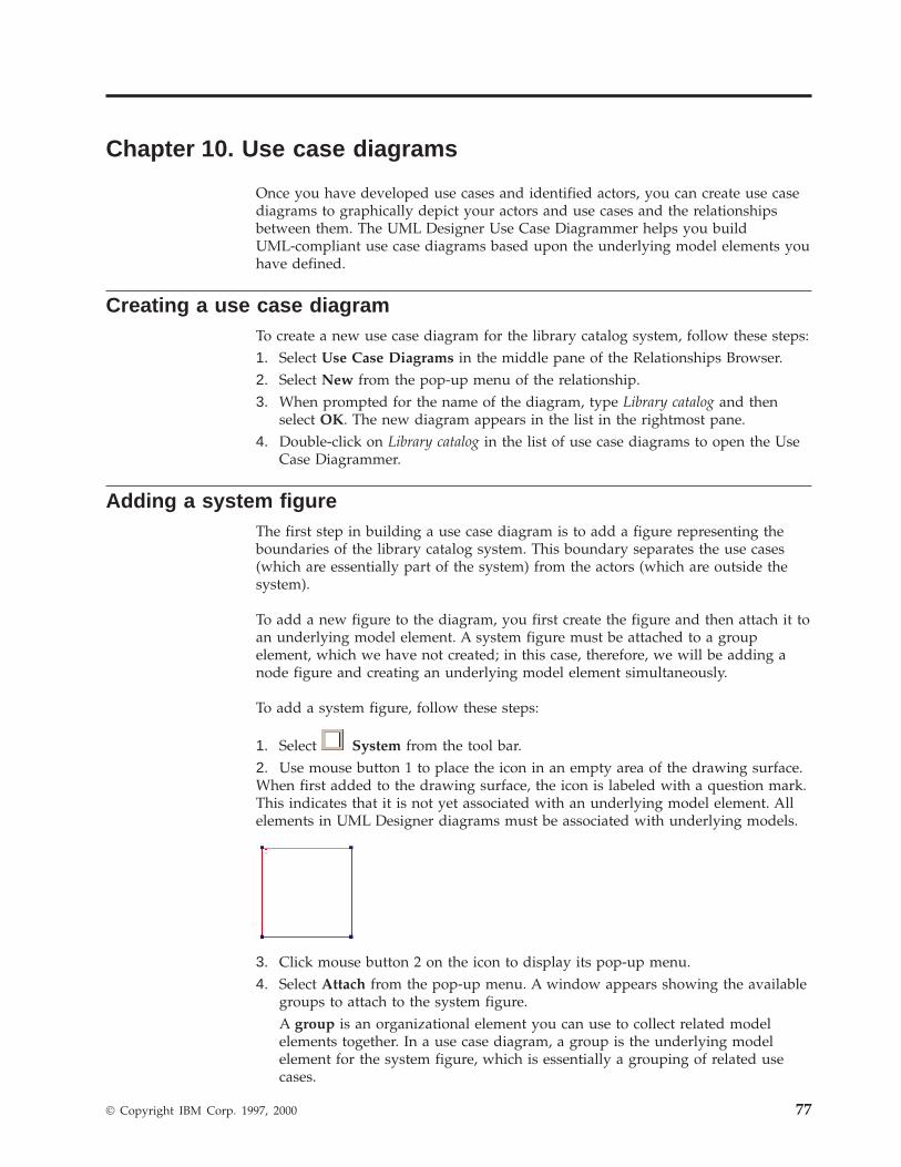
Chapter 10. Use case diagrams
Once you have developed use cases and identified actors, you can create use casediagrams to graphically depict your actors and use cases and the relationshipsbetween them. The UML Designer Use Case Diagrammer helps you buildUML-compliant use case diagrams based upon the underlying model elements youhave defined.
Creating a use case diagramTo create a new use case diagram for the library catalog system, follow these steps:1. Select Use Case Diagrams in the middle pane of the Relationships Browser.2. Select New from the pop-up menu of the relationship.3. When prompted for the name of the diagram, type Library catalog and then
select OK. The new diagram appears in the list in the rightmost pane.4. Double-click on Library catalog in the list of use case diagrams to open the Use
Case Diagrammer.
Adding a system figureThe first step in building a use case diagram is to add a figure representing theboundaries of the library catalog system. This boundary separates the use cases(which are essentially part of the system) from the actors (which are outside thesystem).
To add a new figure to the diagram, you first create the figure and then attach it toan underlying model element. A system figure must be attached to a groupelement, which we have not created; in this case, therefore, we will be adding anode figure and creating an underlying model element simultaneously.
To add a system figure, follow these steps:
1. Select System from the tool bar.2. Use mouse button 1 to place the icon in an empty area of the drawing surface.When first added to the drawing surface, the icon is labeled with a question mark.This indicates that it is not yet associated with an underlying model element. Allelements in UML Designer diagrams must be associated with underlying models.
3. Click mouse button 2 on the icon to display its pop-up menu.4. Select Attach from the pop-up menu. A window appears showing the available
groups to attach to the system figure.A group is an organizational element you can use to collect related modelelements together. In a use case diagram, a group is the underlying modelelement for the system figure, which is essentially a grouping of related usecases.
© Copyright IBM Corp. 1997, 2000 77
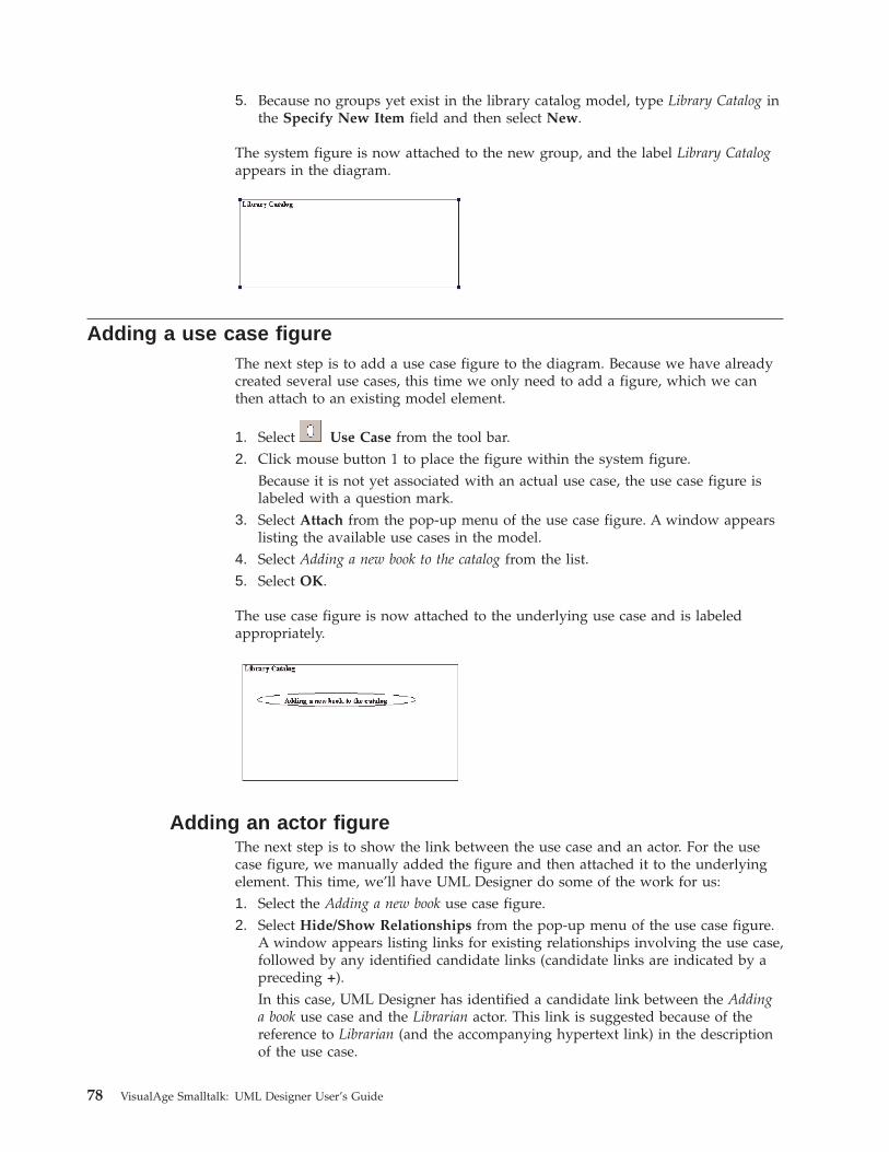
5. Because no groups yet exist in the library catalog model, type Library Catalog inthe Specify New Item field and then select New.
The system figure is now attached to the new group, and the label Library Catalogappears in the diagram.
Adding a use case figureThe next step is to add a use case figure to the diagram. Because we have alreadycreated several use cases, this time we only need to add a figure, which we canthen attach to an existing model element.
1. Select Use Case from the tool bar.2. Click mouse button 1 to place the figure within the system figure.
Because it is not yet associated with an actual use case, the use case figure islabeled with a question mark.
3. Select Attach from the pop-up menu of the use case figure. A window appearslisting the available use cases in the model.
4. Select Adding a new book to the catalog from the list.5. Select OK.
The use case figure is now attached to the underlying use case and is labeledappropriately.
Adding an actor figureThe next step is to show the link between the use case and an actor. For the usecase figure, we manually added the figure and then attached it to the underlyingelement. This time, we’ll have UML Designer do some of the work for us:1. Select the Adding a new book use case figure.2. Select Hide/Show Relationships from the pop-up menu of the use case figure.
A window appears listing links for existing relationships involving the use case,followed by any identified candidate links (candidate links are indicated by apreceding +).In this case, UML Designer has identified a candidate link between the Addinga book use case and the Librarian actor. This link is suggested because of thereference to Librarian (and the accompanying hypertext link) in the descriptionof the use case.
78 VisualAge Smalltalk: UML Designer User’s Guide
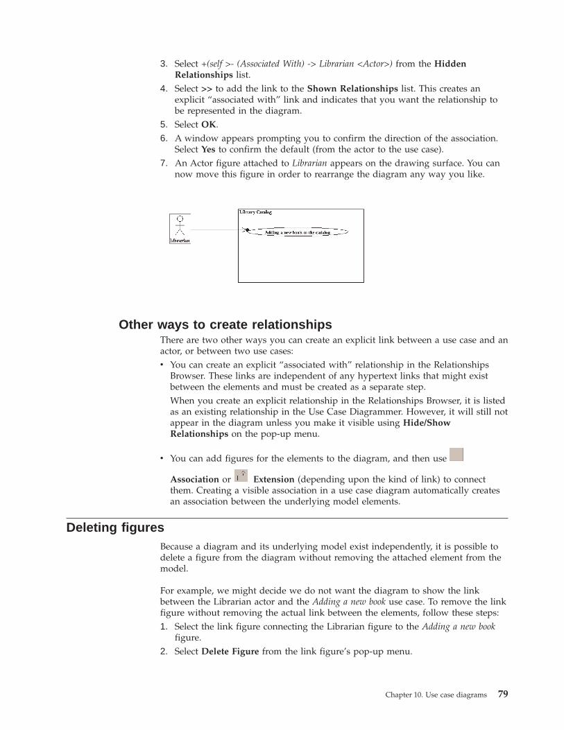
3. Select +(self >- (Associated With) -> Librarian <Actor>) from the HiddenRelationships list.
4. Select >> to add the link to the Shown Relationships list. This creates anexplicit “associated with” link and indicates that you want the relationship tobe represented in the diagram.
5. Select OK.6. A window appears prompting you to confirm the direction of the association.
Select Yes to confirm the default (from the actor to the use case).7. An Actor figure attached to Librarian appears on the drawing surface. You can
now move this figure in order to rearrange the diagram any way you like.
Other ways to create relationshipsThere are two other ways you can create an explicit link between a use case and anactor, or between two use cases:v You can create an explicit “associated with” relationship in the Relationships
Browser. These links are independent of any hypertext links that might existbetween the elements and must be created as a separate step.When you create an explicit relationship in the Relationships Browser, it is listedas an existing relationship in the Use Case Diagrammer. However, it will still notappear in the diagram unless you make it visible using Hide/ShowRelationships on the pop-up menu.
v You can add figures for the elements to the diagram, and then use
Association or Extension (depending upon the kind of link) to connectthem. Creating a visible association in a use case diagram automatically createsan association between the underlying model elements.
Deleting figuresBecause a diagram and its underlying model exist independently, it is possible todelete a figure from the diagram without removing the attached element from themodel.
For example, we might decide we do not want the diagram to show the linkbetween the Librarian actor and the Adding a new book use case. To remove the linkfigure without removing the actual link between the elements, follow these steps:1. Select the link figure connecting the Librarian figure to the Adding a new book
figure.2. Select Delete Figure from the link figure’s pop-up menu.
Chapter 10. Use case diagrams 79

To confirm that the link still exists (even though it is no longer shown), selectHide/Show Relationships from the Librarian figure’s pop-up menu. You shouldstill see the link listed as an existing relationship. (To restore the figure to thediagram, use the >> button to add it back to the list of shown relationships.)
80 VisualAge Smalltalk: UML Designer User’s Guide
Chapter 11. Protocols
By now we have developed a fairly good idea of the requirements of our system,at least good enough for a first pass. We understand what use cases it mustsupport, we’ve identified the actors and things, and we know what theirresponsibilities are. The next step is to begin analysis of the system, in order tostart figuring out how we will satisfy these requirements.
At this point, your first instinct might be to begin writing code, implementingthings as objects and responsibilities as methods. A better approach, however, is tomore closely examine the responsibilities of the things in the system in order tounderstand how they work together. We can do this through the use of protocols.(In fact, you can often do both: go ahead and sketch out some classes, but thencome back to analysis and use protocols to make sure the design is watertight.)
Rigorous use of protocols guarantees substitutability: any class conforming to agiven protocol (or to one refining that protocol) can be substituted for any otherclass conforming to that same protocol. If a class conforms to the expectedprotocol, type mismatches cannot happen. In Smalltalk terms, this means nevergetting a doesNotUnderstand message.
Protocols and thingsA reasonable initial assumption in modeling is that there will be one protocol (andtherefore one type) for each defined thing. In this simple mapping, theresponsibilities of the thing become message specifications in the protocol, definedwith more detail and more precision. This one-to-one mapping does not alwayshold true, but it’s a good place to start.
Protocols provide an intermediate step in the complex transformation ofrequirements into implementation code. Protocols themselves are not code, but areabstract interface specifications that can be transformed into an OOimplementation in a fairly straightforward manner.
Generating a protocolOnce you have defined a thing and its responsibilities, you can use them toautomatically generate a protocol. When generating a protocol, UML Designerassumes the default mapping of one message specification for each responsibility,and it uses the names of the responsibilities to generate a default message name.You can change this afterward if the generated message name is not satisfactory.You can also make other manual changes, like adding message specifications,splitting a protocol into two, or merging two protocols into one.
We’ve defined several responsibilities for the thing Catalog, so we can nowgenerate a protocol that implements the thing. To generate a protocol for Catalog,follow these steps:1. Select Things in the middle pane of the Relationships Browser.2. Select Catalog from the list of things.3. Select Transforms→Generate Protocol from the pop-up menu of Catalog.4. In the window that appears, select Catalog from the Protocol Names list.
© Copyright IBM Corp. 1997, 2000 81
5. You can specify several options that affect the generated protocol:v If you select Delete Existing Messages, the messages in an existing protocol
will be deleted before the new messages are generated. (This option isavailable only if you are regenerating an existing protocol.)
v If you select Overwrite Existing Messages, the messages in an existingprotocol will be overwritten, but you can still reload them if you want to getthem back. (This option is available only if you are regenerating an existingprotocol.)
v If you select Generate Associations, UML Designer will create associationsbetween the generated messages and the responsibilities they implement.(This option is selected by default.)
v If you select Generate Messages, UML Designer will generate messages inthe protocol. Otherwise, the generated protocol is empty. (This option isselected by default.)
For our example, accept the default options and select OK to generate theprotocol.
Message specificationsTo take a look at the protocol we just generated, select Protocols in the middlepane of the Relationships Browser and then double-click on <Catalog>. A browseropens from which we can explore the <Catalog> protocol.
In the new browser, select Messages in the middle pane. In the rightmost pane,you should see a list of the message specifications that were automaticallygenerated for the protocol, based upon the responsibilities we defined earlier. UMLDesigner uses a straightforward transformation to convert responsibility namesinto message names that could eventually become Smalltalk or Java methodnames. If the generated message names are not satisfactory, you can change them.
For the <Catalog> protocol, the following message specifications were automaticallygenerated from the responsibilities of the Catalog thing:
Responsibility Generated message specification
Add catalog entry #addCatalogEntry:
Assign accession number to entry#assignAccessionNumberToEntry:
Find entry by search criteria #findEntryBySearchCriteria
Remove catalog entry #removeCatalogEntry:
Note that some of the generated message specifications end in colons, indicatingthat they take parameters. This is because the corresponding responsibilities eachhas a collaborating participant defined. To see more information about parameters,double-click on #addCatalogEntry:. A browser opens on the #addCatalogEntry:message specification, showing additional details of the message specification.
Select Parameters in the middle pane of the browser. In the rightmost pane, youshould see a single parameter listed: aCatalogEntry. This parameter wasautomatically generated because the Add catalog entry responsibility had a link toCatalog entry as a collaborating participant. Because of this relationship, UMLDesigner assumes that an object representing the participating Catalog entry thingwill have to be passed to the method implementing the Add catalog entryresponsibility.
82 VisualAge Smalltalk: UML Designer User’s Guide
The type of a parameter must be defined by a protocol, and at this stage we havenot defined a protocol for Catalog entry. Therefore, the parameters of the generatedmessage specifications all have the default type <Object>, even though thegenerated parameter names (such as aCatalogEntry) might suggest a different type.Later, after you have generated protocols for all of the things in your design, youcan change the parameters of the message specifications to the correct types.
Generating using idiomsFor another Thing element, Catalog Entry, we defined several responsibilities usingthe Value idiom. Let’s see how these responsibilities become protocol messages:1. Generate a protocol for Catalog Entry using the same procedure you used for
Catalog (select Transform→Generate Protocol and accept the default options).2. After you generate the protocol, select Protocols from the list of relationships
and then select the new protocol, <CatalogEntry>.3. Double-click on <CatalogEntry> to open a browser on the protocol.4. In the middle pane of the new browser, select Messages. You should see a list
of messages defined in the protocol:v accessionNumber
v accessionNumber:
v author
v author:
v title
v title:
These messages are the getters and setters for the values kept by the catalogentry. UML Designer automatically generated these messages based on thethree responsibilities we specified for the CatalogEntry Thing.
5. In the middle pane of the browser, select Attributes. You should see a list ofattributes defined in the protocol:v accessionNumber
v author
v title
These attributes represent the values kept by the catalog entry. UML Designeralso generated these attributes based on the three responsibilities we specifiedfor the CatalogEntry Thing.
Changing parameter and attribute typesWhen we defined the responsibilities of Catalog Entry, we didn’t specify anyparticipants. We can now make changes to the generated messages to specify theappropriate types for the messages and attributes.
This time, let’s use the Path Browser, which will allow us to see everything weneed in one browser. The Path Browser shows the successive navigation of not justone relationship, but of up to four relationships, starting from the selected sourceelement. With the Path Browser, therefore, we can browse a protocol, its messagespecifications, the parameters of a selected message, and the type of a selectedparameter all in the same browser. (See “The Path Browser” on page 30 for moreinformation about the Path Browser.)
Chapter 11. Protocols 83
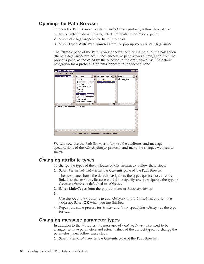
Opening the Path BrowserTo open the Path Browser on the <CatalogEntry> protocol, follow these steps:1. In the Relationships Browser, select Protocols in the middle pane.2. Select <CatalogEntry> in the list of protocols.3. Select Open With→Path Browser from the pop-up menu of <CatalogEntry>.
The leftmost pane of the Path Browser shows the starting point of the navigation(the <CatalogEntry> protocol). Each successive pane shows a navigation from theprevious pane, as indicated by the selection in the drop-down list. The defaultnavigation for a protocol, Contents, appears in the second pane.
We can now use the Path Browser to browse the attributes and messagespecifications of the <CatalogEntry> protocol, and make the changes we need tomake.
Changing attribute typesTo change the types of the attributes of <CatalogEntry>, follow these steps:1. Select #accessionNumber from the Contents pane of the Path Browser.
The next pane shows the default navigation, the types (protocols) currentlylinked to the attribute. Because we did not specify any participants, the type of#accessionNumber is defaulted to <Object>.
2. Select Link→Types from the pop-up menu of #accessionNumber.3.
Use the << and >> buttons to add <Integer> to the Linked list and remove<Object>. Select OK when you are finished.
4. Repeat the same process for #author and #title, specifying <String> as the typefor each.
Changing message parameter typesIn addition to the attributes, the messages of <CatalogEntry> also need to bechanged to have parameters and return values of the correct types. To change theparameter types, follow these steps:1. Select accessionNumber: in the Contents pane of the Path Browser.
84 VisualAge Smalltalk: UML Designer User’s Guide
The default navigation for a message specification, Characterized by, appearsin the third pane. This navigation shows all of the parameters and returnvalues of the selected message specification. (If you wanted to see only theinput parameters, you could select the Parameters navigation in the thirdpane).
2. Select anAccessionNumber in the Characterized by pane.The default navigation for a parameter, Types, appears in the fourth pane. Thisnavigation shows the types (protocols) currently linked to this parameter.Currently, the type is defaulted to <Object>.
3. Select Link→Types from the pop-up menu of anAccessionNumber. A windowappears prompting you to select which object types should be linked to theselected parameter.
4. Use the << and >> buttons to add <Integer> to the Linked list and remove<Object>. Select OK when you are finished.
5. Use the same procedure to change the parameter types for the other settermethods, author: and title:. Both should take parameters of type <String>.
Changing return value typesChanging a return value type is similar to changing a parameter type. To changethe return value types for the messages of <CatalogEntry>, follow these steps:1. Select accessionNumber: in the Contents pane of the Path Browser.2. Select returns in the Characterized by pane. The Type pane indicates that the
return type is currently unspecified.3. Select Link→Types from the pop-up menu of returns. A window appears
prompting you to select which object type should be linked to the selectedparameter.
4. Use the >> to add <Integer> to the Linked list. You do not need to removeanything from the list; a return value has only one type by definition, so theprevious value is automatically removed. Select OK when you are finished.
5. Use the same procedure to change the parameter types for the other methods.accessionNumber should return <Integer>, while the getter and setter methodsfor author and title should all return <String>.
Defining a message manuallySuppose we now decide we want to add getter and setter messages to<CatalogEntry> for storing the Dewey number. We could go back and define this asa responsibility of the Catalog Entry Thing and regenerate the protocol, but let’s trydirectly adding the responsibility to the protocol.
To add the new messages, follow these steps:1. Select Protocols in the Relationships Browser.2. Select <CatalogEntry> from the list of protocols.3. Select New→Message Specification from the pop-up menu of <CatalogEntry>.4. When prompted for the message specification, type the following (be sure to
include spaces on either side of the colon):deweyNumber : <String>
This is the formal UML syntax declaring a message specification. It indicates aunary message with no parameters that returns an object of type <String>. Thisis the getter message for the deweyNumber attribute.
Chapter 11. Protocols 85

5. Use New→Message Specification again to add the setter message for thedeweyNumber attribute:deweyNumber: (number: <String>): <String>
This is the UML syntax declaring a unary message taking one parameter oftype <String> and returning a <String>.
86 VisualAge Smalltalk: UML Designer User’s Guide
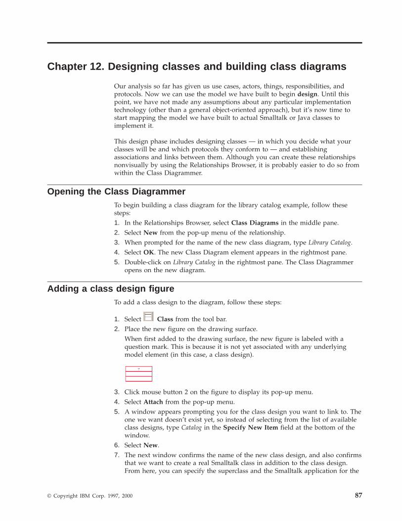
Chapter 12. Designing classes and building class diagrams
Our analysis so far has given us use cases, actors, things, responsibilities, andprotocols. Now we can use the model we have built to begin design. Until thispoint, we have not made any assumptions about any particular implementationtechnology (other than a general object-oriented approach), but it’s now time tostart mapping the model we have built to actual Smalltalk or Java classes toimplement it.
This design phase includes designing classes — in which you decide what yourclasses will be and which protocols they conform to — and establishingassociations and links between them. Although you can create these relationshipsnonvisually by using the Relationships Browser, it is probably easier to do so fromwithin the Class Diagrammer.
Opening the Class DiagrammerTo begin building a class diagram for the library catalog example, follow thesesteps:1. In the Relationships Browser, select Class Diagrams in the middle pane.2. Select New from the pop-up menu of the relationship.3. When prompted for the name of the new class diagram, type Library Catalog.4. Select OK. The new Class Diagram element appears in the rightmost pane.5. Double-click on Library Catalog in the rightmost pane. The Class Diagrammer
opens on the new diagram.
Adding a class design figureTo add a class design to the diagram, follow these steps:
1. Select Class from the tool bar.2. Place the new figure on the drawing surface.
When first added to the drawing surface, the new figure is labeled with aquestion mark. This is because it is not yet associated with any underlyingmodel element (in this case, a class design).
3. Click mouse button 2 on the figure to display its pop-up menu.4. Select Attach from the pop-up menu.5. A window appears prompting you for the class design you want to link to. The
one we want doesn’t exist yet, so instead of selecting from the list of availableclass designs, type Catalog in the Specify New Item field at the bottom of thewindow.
6. Select New.7. The next window confirms the name of the new class design, and also confirms
that we want to create a real Smalltalk class in addition to the class design.From here, you can specify the superclass and the Smalltalk application for the
© Copyright IBM Corp. 1997, 2000 87
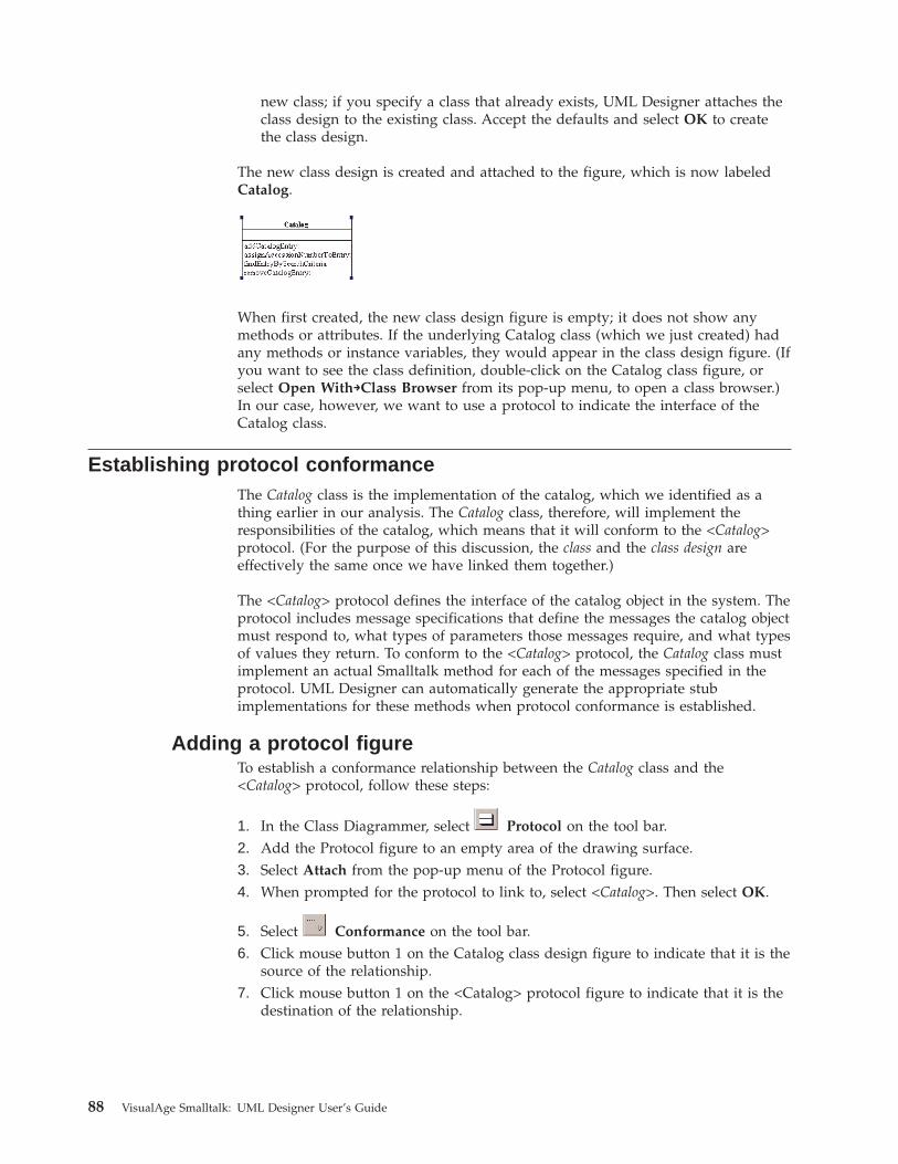
new class; if you specify a class that already exists, UML Designer attaches theclass design to the existing class. Accept the defaults and select OK to createthe class design.
The new class design is created and attached to the figure, which is now labeledCatalog.
When first created, the new class design figure is empty; it does not show anymethods or attributes. If the underlying Catalog class (which we just created) hadany methods or instance variables, they would appear in the class design figure. (Ifyou want to see the class definition, double-click on the Catalog class figure, orselect Open With→Class Browser from its pop-up menu, to open a class browser.)In our case, however, we want to use a protocol to indicate the interface of theCatalog class.
Establishing protocol conformanceThe Catalog class is the implementation of the catalog, which we identified as athing earlier in our analysis. The Catalog class, therefore, will implement theresponsibilities of the catalog, which means that it will conform to the <Catalog>protocol. (For the purpose of this discussion, the class and the class design areeffectively the same once we have linked them together.)
The <Catalog> protocol defines the interface of the catalog object in the system. Theprotocol includes message specifications that define the messages the catalog objectmust respond to, what types of parameters those messages require, and what typesof values they return. To conform to the <Catalog> protocol, the Catalog class mustimplement an actual Smalltalk method for each of the messages specified in theprotocol. UML Designer can automatically generate the appropriate stubimplementations for these methods when protocol conformance is established.
Adding a protocol figureTo establish a conformance relationship between the Catalog class and the<Catalog> protocol, follow these steps:
1. In the Class Diagrammer, select Protocol on the tool bar.2. Add the Protocol figure to an empty area of the drawing surface.3. Select Attach from the pop-up menu of the Protocol figure.4. When prompted for the protocol to link to, select <Catalog>. Then select OK.
5. Select Conformance on the tool bar.6. Click mouse button 1 on the Catalog class design figure to indicate that it is the
source of the relationship.7. Click mouse button 1 on the <Catalog> protocol figure to indicate that it is the
destination of the relationship.
88 VisualAge Smalltalk: UML Designer User’s Guide
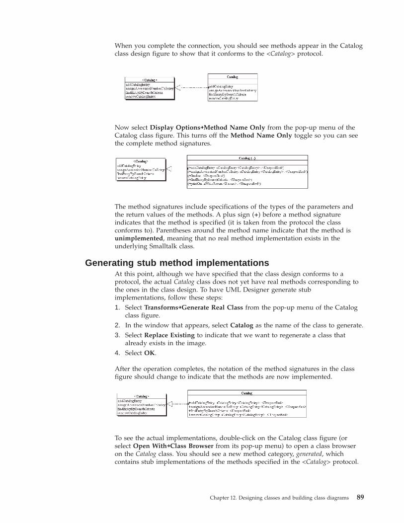
When you complete the connection, you should see methods appear in the Catalogclass design figure to show that it conforms to the <Catalog> protocol.
Now select Display Options→Method Name Only from the pop-up menu of theCatalog class figure. This turns off the Method Name Only toggle so you can seethe complete method signatures.
The method signatures include specifications of the types of the parameters andthe return values of the methods. A plus sign (+) before a method signatureindicates that the method is specified (it is taken from the protocol the classconforms to). Parentheses around the method name indicate that the method isunimplemented, meaning that no real method implementation exists in theunderlying Smalltalk class.
Generating stub method implementationsAt this point, although we have specified that the class design conforms to aprotocol, the actual Catalog class does not yet have real methods corresponding tothe ones in the class design. To have UML Designer generate stubimplementations, follow these steps:1. Select Transforms→Generate Real Class from the pop-up menu of the Catalog
class figure.2. In the window that appears, select Catalog as the name of the class to generate.3. Select Replace Existing to indicate that we want to regenerate a class that
already exists in the image.4. Select OK.
After the operation completes, the notation of the method signatures in the classfigure should change to indicate that the methods are now implemented.
To see the actual implementations, double-click on the Catalog class figure (orselect Open With→Class Browser from its pop-up menu) to open a class browseron the Catalog class. You should see a new method category, generated, whichcontains stub implementations of the methods specified in the <Catalog> protocol.
Chapter 12. Designing classes and building class diagrams 89
Adding more elementsWe’ve now diagrammed the Catalog class and its conformance to the <Catalog>protocol. In order to completely diagram our design as it stands, we need to addthe other classes and protocols we’ve come up with so we can show theirrelationships to one another.
To add the other classes and protocols, follow these steps:
1. Select Class on the tool bar to add a second class figure to the diagram.2. Select Attach from the pop-up menu of the new figure.3. Attach the new figure to a new class design called Library. Specify that you
want to generate a real Smalltalk class.4. Use the same procedure to add another class figure attached to a class design
(and Smalltalk class) called CatalogEntry.
5. Now select Protocol on the tool bar to add a second protocol figure to thediagram.
6. Select Attach from the pop-up menu of the new figure.7. Attach the new figure to the <CatalogEntry> protocol.
You should now have five design elements represented on the diagram:v Catalog classv <Catalog> protocolv CatalogEntry classv <CatalogEntry> protocolv Library class
Creating associationsTo complete our first pass at a class diagram, we must now connect the designelements to one another to show the associations with one another. As you makeconnections between design elements, you can move the elements around on thedrawing surface in order to keep the diagram neat and readable. The visualarrangement of the figures in the diagram has no effect on the underlying model.
A closer look at associationsBefore we add associations to our class diagram, we need to take a close look atassociations and their attributes.
The associations we’ve created up until this point (such as the connection betweenthe Catalog class and the <Catalog> protocol) are more correctly called links. InUML terms, a link is an instance of an association, meaning that a semanticrelationship exists between the linked elements. A link represents an instance ofone of the types of relationships predefined by the UML and UML Designermetamodels. Protocol conformance is an example of such a relationship; the linkbetween the Catalog class and the <Catalog> protocol is a specific instance of aconformance relationship.
On the other hand, an association defines a type of relationship, but not a specificinstance of such a relationship. In other words, an association defines a possibleconnection between objects in the system defined by your model, rather than being
90 VisualAge Smalltalk: UML Designer User’s Guide
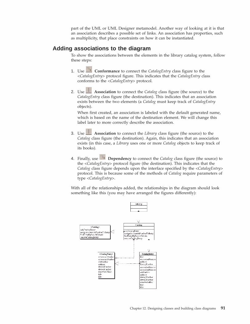
part of the UML or UML Designer metamodel. Another way of looking at it is thatan association describes a possible set of links. An association has properties, suchas multiplicity, that place constraints on how it can be instantiated.
Adding associations to the diagramTo show the associations between the elements in the library catalog system, followthese steps:
1. Use Conformance to connect the CatalogEntry class figure to the<CatalogEntry> protocol figure. This indicates that the CatalogEntry classconforms to the <CatalogEntry> protocol.
2. Use Association to connect the Catalog class figure (the source) to theCatalogEntry class figure (the destination). This indicates that an associationexists between the two elements (a Catalog must keep track of CatalogEntryobjects).When first created, an association is labeled with the default generated name,which is based on the name of the destination element. We will change thislabel later to more correctly describe the association.
3. Use Association to connect the Library class figure (the source) to theCatalog class figure (the destination). Again, this indicates that an associationexists (in this case, a Library uses one or more Catalog objects to keep track ofits books).
4. Finally, use Dependency to connect the Catalog class figure (the source) tothe <CatalogEntry> protocol figure (the destination). This indicates that theCatalog class figure depends upon the interface specified by the <CatalogEntry>protocol. This is because some of the methods of Catalog require parameters oftype <CatalogEntry>.
With all of the relationships added, the relationships in the diagram should looksomething like this (you may have arranged the figures differently):
Chapter 12. Designing classes and building class diagrams 91
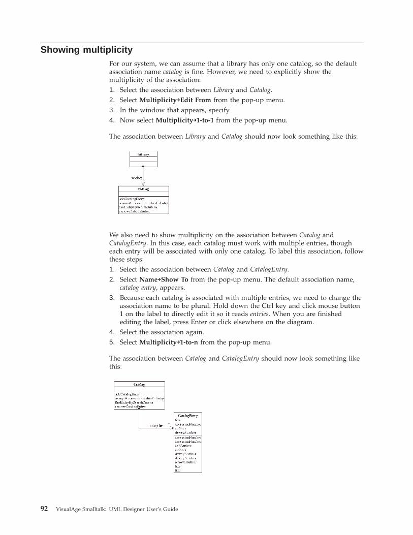
Showing multiplicityFor our system, we can assume that a library has only one catalog, so the defaultassociation name catalog is fine. However, we need to explicitly show themultiplicity of the association:1. Select the association between Library and Catalog.2. Select Multiplicity→Edit From from the pop-up menu.3. In the window that appears, specify4. Now select Multiplicity→1-to-1 from the pop-up menu.
The association between Library and Catalog should now look something like this:
We also need to show multiplicity on the association between Catalog andCatalogEntry. In this case, each catalog must work with multiple entries, thougheach entry will be associated with only one catalog. To label this association, followthese steps:1. Select the association between Catalog and CatalogEntry.2. Select Name→Show To from the pop-up menu. The default association name,
catalog entry, appears.3. Because each catalog is associated with multiple entries, we need to change the
association name to be plural. Hold down the Ctrl key and click mouse button1 on the label to directly edit it so it reads entries. When you are finishedediting the label, press Enter or click elsewhere on the diagram.
4. Select the association again.5. Select Multiplicity→1-to-n from the pop-up menu.
The association between Catalog and CatalogEntry should now look something likethis:
92 VisualAge Smalltalk: UML Designer User’s Guide
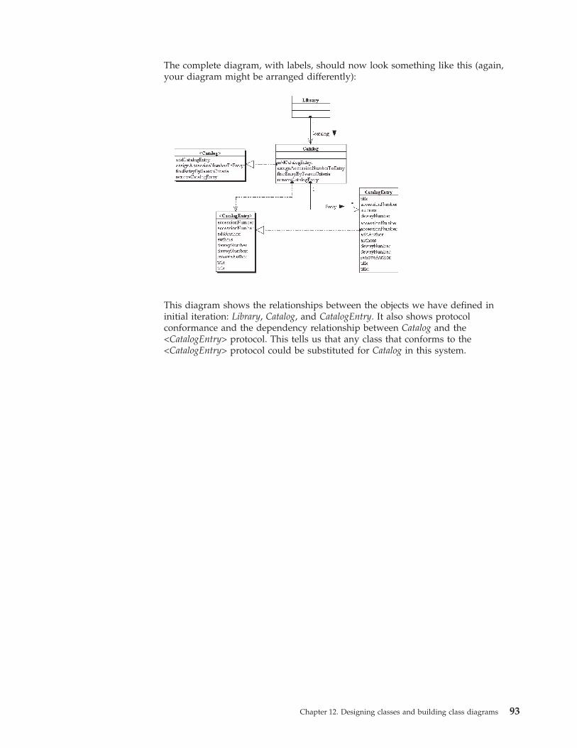
The complete diagram, with labels, should now look something like this (again,your diagram might be arranged differently):
This diagram shows the relationships between the objects we have defined ininitial iteration: Library, Catalog, and CatalogEntry. It also shows protocolconformance and the dependency relationship between Catalog and the<CatalogEntry> protocol. This tells us that any class that conforms to the<CatalogEntry> protocol could be substituted for Catalog in this system.
Chapter 12. Designing classes and building class diagrams 93

94 VisualAge Smalltalk: UML Designer User’s Guide
Chapter 13. Modeling existing Smalltalk classes
In some situations, your model might need to describe one or more Smalltalkclasses that have already been implemented, “reverse engineering” analysis anddesign artifacts.
With UML Designer, you can accomplish this by creating a corresponding classdesign in your model for each existing Smalltalk class. Any Smalltalk class can beattached to a class design, whether or not the class was generated by UMLDesigner. You can also create protocols based on the methods of existing classes.
The simplest way to attach a class design to an existing class is to use the classname as the class design name. When you create a class design with the samename as an existing class, UML Designer by default suggests the existing classwhen prompting which class the class design should be attached to. By acceptingthe defaults, you can quickly create a class design and link it to an existing class.
However, you can also create a class design with a different name. Whenprompted for the real class to link to, you can select any class that exists in theimage.
Attaching a class design to an existing classFor example, suppose we have a new requirement for the library catalog system:we now want to track circulation, keeping records of which patrons have checkedout which books. This means we will almost certainly need a class to representborrowers. We could choose to build a new Borrower class for this purpose; butsuppose we then find out that we already have a LibraryPatron class that wasimplemented for a system that prints library cards. The LibraryPatron class has thefollowing attributes, each with a getter and setter method:v namev addressv telephonev card number
This seems to be everything we need, so now we just need to incorporate theLibraryPatron class into our Library Catalog model. To do so, follow these steps:1. Make sure a LibraryPatron class exists in the image. (You can create the class
yourself using the standard Smalltalk browsers; just add instance variables andstub getters and setters for the attributes above.)
2. In the Class Diagrammer, add a new class figure to the drawing surface.3. Select Attach from the pop-up menu of the new figure.4. When prompted for the class design to link to, type Borrower in the Specify
New Item field.5. Select New.6. In the next window, make sure Link To Real Class is selected.7. Specify LibraryPatron in the Class Name field. (The name of the underlying
Smalltalk class does not have to be the same as the name of the attached classdesign.)
© Copyright IBM Corp. 1997, 2000 95
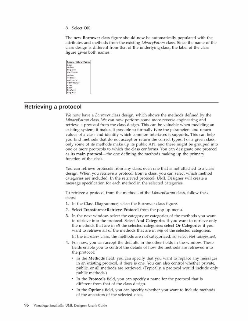
8. Select OK.
The new Borrower class figure should now be automatically populated with theattributes and methods from the existing LibraryPatron class. Since the name of theclass design is different from that of the underlying class, the label of the classfigure gives both names.
Retrieving a protocolWe now have a Borrower class design, which shows the methods defined by theLibraryPatron class. We can now perform some more reverse engineering andretrieve a protocol from the class design. This can be valuable when modeling anexisting system; it makes it possible to formally type the parameters and returnvalues of a class and identify which common interfaces it supports. This can helpyou find methods that do not accept or return the correct types. For a given class,only some of its methods make up its public API, and these might be grouped intoone or more protocols to which the class conforms. You can designate one protocolas its main protocol—the one defining the methods making up the primaryfunction of the class.
You can retrieve protocols from any class, even one that is not attached to a classdesign. When you retrieve a protocol from a class, you can select which methodcategories are included. In the retrieved protocol, UML Designer will create amessage specification for each method in the selected categories.
To retrieve a protocol from the methods of the LibraryPatron class, follow thesesteps:1. In the Class Diagrammer, select the Borrower class figure.2. Select Transforms→Retrieve Protocol from the pop-up menu.3. In the next window, select the category or categories of the methods you want
to retrieve into the protocol. Select And Categories if you want to retrieve onlythe methods that are in all the selected categories; select Or Categories if youwant to retrieve all of the methods that are in any of the selected categories.In the Borrower class, the methods are not categorized, so select Not categorized.
4. For now, you can accept the defaults in the other fields in the window. Thesefields enable you to control the details of how the methods are retrieved intothe protocol:v In the Methods field, you can specify that you want to replace any messages
in an existing protocol, if there is one. You can also control whether private,public, or all methods are retrieved. (Typically, a protocol would include onlypublic methods.)
v In the Protocols field, you can specify a name for the protocol that isdifferent from that of the class design.
v In the Options field, you can specify whether you want to include methodsof the ancestors of the selected class.
96 VisualAge Smalltalk: UML Designer User’s Guide
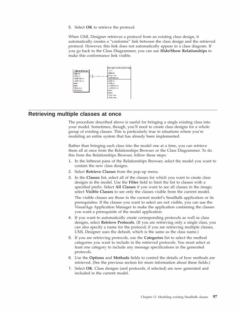
5. Select OK to retrieve the protocol.
When UML Designer retrieves a protocol from an existing class design, itautomatically creates a “conforms” link between the class design and the retrievedprotocol. However, this link does not automatically appear in a class diagram. Ifyou go back to the Class Diagrammer, you can use Hide/Show Relationships tomake this conformance link visible.
Retrieving multiple classes at onceThe procedure described above is useful for bringing a single existing class intoyour model. Sometimes, though, you’ll need to create class designs for a wholegroup of existing classes. This is particularly true in situations where you’remodeling an entire system that has already been implemented.
Rather than bringing each class into the model one at a time, you can retrievethem all at once from the Relationships Browser or the Class Diagrammer. To dothis from the Relationships Browser, follow these steps:1. In the leftmost pane of the Relationships Browser, select the model you want to
contain the new class designs.2. Select Retrieve Classes from the pop-up menu.3. In the Classes list, select all of the classes for which you want to create class
designs in the model. Use the Filter field to limit the list to classes with aspecified prefix. Select All Classes if you want to see all classes in the image;select Visible Classes to see only the classes visible from the current model.The visible classes are those in the current model’s Smalltalk application or itsprerequisites. If the classes you want to select are not visible, you can use theVisualAge Application Manager to make the application containing the classesyou want a prerequisite of the model application.
4. If you want to automatically create corresponding protocols as well as classdesigns, select Retrieve Protocols. (If you are retrieving only a single class, youcan also specify a name for the protocol; if you are retrieving multiple classes,UML Designer uses the default, which is the same as the class name.)
5. If you are retrieving protocols, use the Categories list to select the methodcategories you want to include in the retrieved protocols. You must select atleast one category to include any message specifications in the generatedprotocols.
6. Use the Options and Methods fields to control the details of how methods areretrieved. (See the previous section for more information about these fields.)
7. Select OK. Class designs (and protocols, if selected) are now generated andincluded in the current model.
Chapter 13. Modeling existing Smalltalk classes 97

98 VisualAge Smalltalk: UML Designer User’s Guide
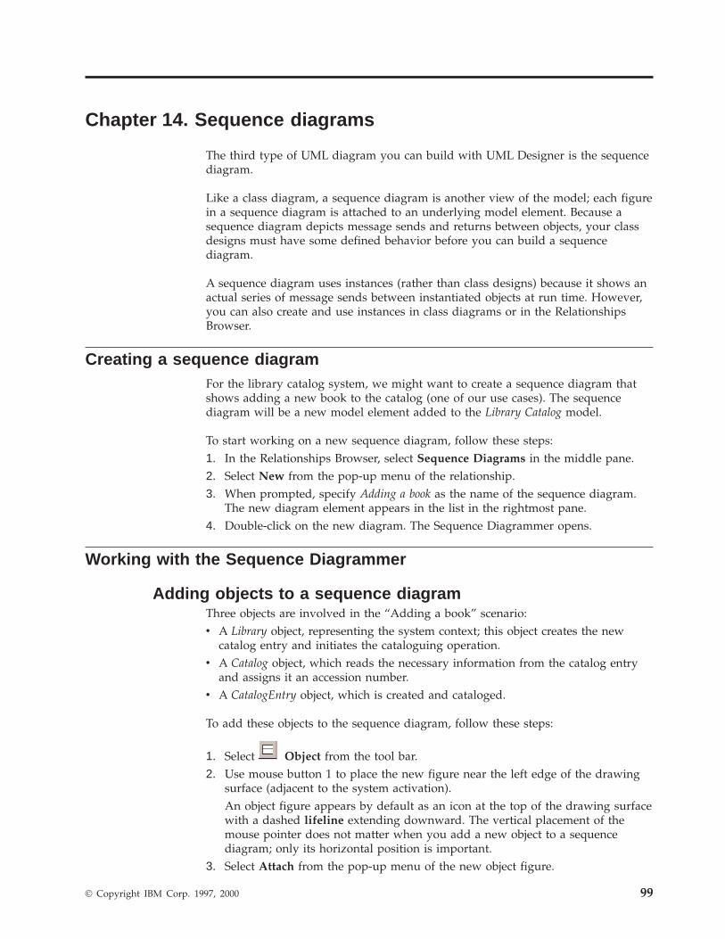
Chapter 14. Sequence diagrams
The third type of UML diagram you can build with UML Designer is the sequencediagram.
Like a class diagram, a sequence diagram is another view of the model; each figurein a sequence diagram is attached to an underlying model element. Because asequence diagram depicts message sends and returns between objects, your classdesigns must have some defined behavior before you can build a sequencediagram.
A sequence diagram uses instances (rather than class designs) because it shows anactual series of message sends between instantiated objects at run time. However,you can also create and use instances in class diagrams or in the RelationshipsBrowser.
Creating a sequence diagramFor the library catalog system, we might want to create a sequence diagram thatshows adding a new book to the catalog (one of our use cases). The sequencediagram will be a new model element added to the Library Catalog model.
To start working on a new sequence diagram, follow these steps:1. In the Relationships Browser, select Sequence Diagrams in the middle pane.2. Select New from the pop-up menu of the relationship.3. When prompted, specify Adding a book as the name of the sequence diagram.
The new diagram element appears in the list in the rightmost pane.4. Double-click on the new diagram. The Sequence Diagrammer opens.
Working with the Sequence Diagrammer
Adding objects to a sequence diagramThree objects are involved in the “Adding a book” scenario:v A Library object, representing the system context; this object creates the new
catalog entry and initiates the cataloguing operation.v A Catalog object, which reads the necessary information from the catalog entry
and assigns it an accession number.v A CatalogEntry object, which is created and cataloged.
To add these objects to the sequence diagram, follow these steps:
1. Select Object from the tool bar.2. Use mouse button 1 to place the new figure near the left edge of the drawing
surface (adjacent to the system activation).An object figure appears by default as an icon at the top of the drawing surfacewith a dashed lifeline extending downward. The vertical placement of themouse pointer does not matter when you add a new object to a sequencediagram; only its horizontal position is important.
3. Select Attach from the pop-up menu of the new object figure.
© Copyright IBM Corp. 1997, 2000 99
4. When prompted, select Library as the class design to link to. UML Designerautomatically creates a new instance element for the class design you select.
5. Select OK. The object figure is now labeled Library.6. Repeat the same procedure for the other two object figures, attaching them to
Catalog and CatalogEntry respectively.
Adding method calls to the diagramTo show the sequence of events involved in adding a book to the catalog, youmust now add figures representing the method calls between the objects in thediagram. Each figure shows a single method call between a sender and a receiver,as well as the return after the method has completed. In addition, the sequencediagram also shows activation on each object’s lifeline, so you can see whichobjects are active (that is, which objects are currently executing in response tomethod calls) at any given time.
In general terms, the sequence of events involved in adding a book to the cataloggoes something like this:1. A librarian (an actor outside the system) uses the library system interface to
create a new catalog entry. The new catalog entry records the informationdescribing the new book.
2. The librarian uses the library system interface to add the new catalog entry tothe catalog.
3. The catalog queries the catalog entry for its descriptive information forindexing purposes.
4. The catalog allocates an accession number and assigns it to the new entry.
Adding the initial method callThe first method call on a sequence diagram must originate from the systemactivation at the left edge (only an active object can send a message to anotherobject). This initial method call represents a call from outside the diagram; in ourdiagram, it represents input from an outside actor initiating the catalogingoperation. We have not yet defined an actual method for Library that would acceptexternal input, so for now we can use the standard yourself method as aplaceholder. This method call does not itself have any significance; it is usedsimply to activate the Library object.
To add this method call to the diagram, follow these steps:
1. Select Method call from the tool bar.2. Click mouse button 1 on the system activation to indicate the source of the
message (in this case, an object outside the diagram).3. Click mouse button 1 on the Library object’s lifeline to indicate the receiver of
the message.
100 VisualAge Smalltalk: UML Designer User’s Guide
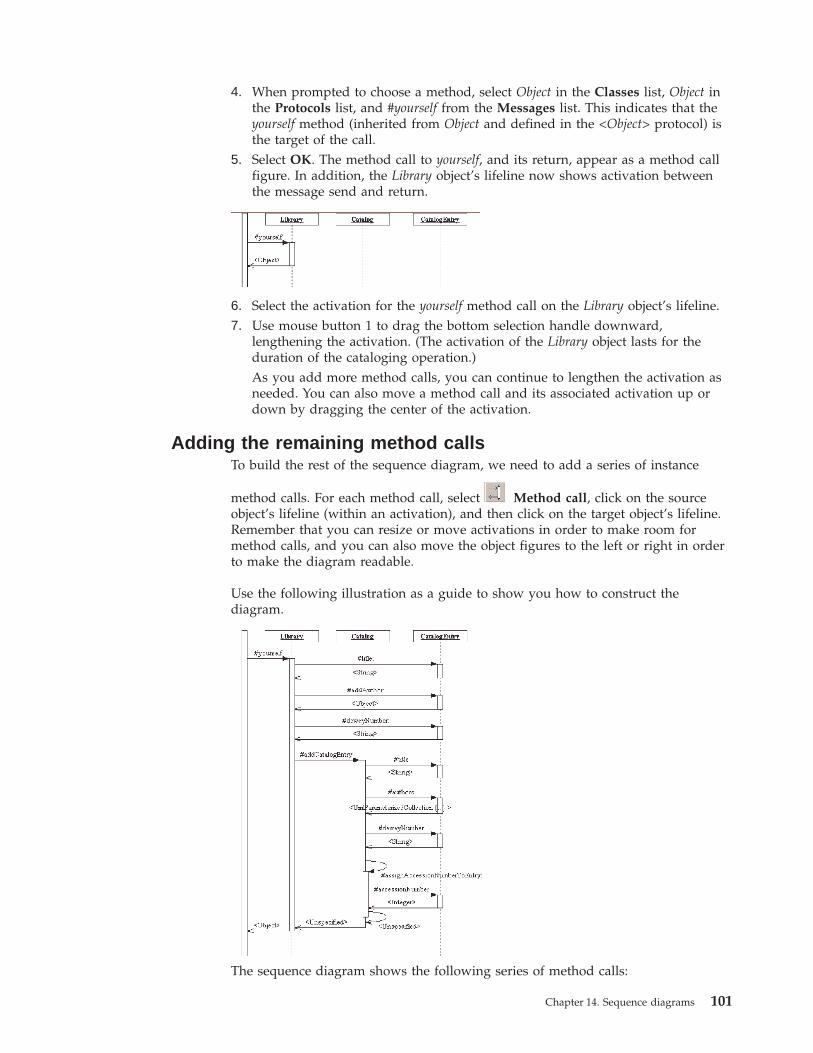
4. When prompted to choose a method, select Object in the Classes list, Object inthe Protocols list, and #yourself from the Messages list. This indicates that theyourself method (inherited from Object and defined in the <Object> protocol) isthe target of the call.
5. Select OK. The method call to yourself, and its return, appear as a method callfigure. In addition, the Library object’s lifeline now shows activation betweenthe message send and return.
6. Select the activation for the yourself method call on the Library object’s lifeline.7. Use mouse button 1 to drag the bottom selection handle downward,
lengthening the activation. (The activation of the Library object lasts for theduration of the cataloging operation.)As you add more method calls, you can continue to lengthen the activation asneeded. You can also move a method call and its associated activation up ordown by dragging the center of the activation.
Adding the remaining method callsTo build the rest of the sequence diagram, we need to add a series of instance
method calls. For each method call, select Method call, click on the sourceobject’s lifeline (within an activation), and then click on the target object’s lifeline.Remember that you can resize or move activations in order to make room formethod calls, and you can also move the object figures to the left or right in orderto make the diagram readable.
Use the following illustration as a guide to show you how to construct thediagram.
The sequence diagram shows the following series of method calls:
Chapter 14. Sequence diagrams 101
1. After instantiating a new CatalogEntry object, the LibraryObject uses settermethods to set the title, author, and deweyNumber attributes of the new catalogentry.
2. Library then sends the message addCatalogEntry: to Catalog, which tells it to takethe new entry, index it, and assign it an accession number.
3. Catalog, now active, uses getter methods to retrieve the title, author, anddeweyNumber attributes of the catalog entry. (At this point there would be someadditional processing to index the new entry, but that behavior is not currentlypart of our model.)
4. Catalog sends the message assignAccessionNumberToEntry: to itself. This methodallocates a new accession number that can then be assigned to a catalog entry.Note the stacked activations on the Catalog lifeline, indicating nested methodexecution.
5. Finally, Catalog sends accessionNumber: to the CatalogEntry, assigning it thenewly allocated accession number.
102 VisualAge Smalltalk: UML Designer User’s Guide
Chapter 15. Publishing models
The UML Designer publishing features can generate formatted output based on thecontents of your model (or a subset of your model), in either HTML or RTFformat.
Publishing is a two-step process:v The first step is to build a Publication element as part of the model. The
Publication element in turn contains a set of Topic elements, each of which islinked to a model element.
v The second step is to generate HTML or RTF output based on the Publicationelement. The output produced can then be browsed or printed.
A Publication element defines the structure and content of a published documentbased on your model. It consists of a series of Topic elements, arranged in ahierarchical fashion; the arrangement of Topic elements corresponds to theorganizational structure of the document that will be produced.
Each Topic element contains a text element; this text is what will appear in thefinal output. The text can consist of literal text or hypertext links (which will beresolved when you generate the final output).
There are two basic ways to publish your model:v Automatically generating a publication element and output in one stepv Manually building a publication element and generating output
Publishing automaticallyThe fastest way to publish your model is to automatically generate the Publicationelement and output document in a single step. This is generally the easiest way tocreate published output, and you can publish any model this way.
To publish automatically, follow these steps:1. In the Relationships Browser, select the element you want to publish. This can
either be the model element or an element within the model.2. If you want to include the element and any elements it links to, select
Publish→With Children from the pop-up menu. For example, you might usethis option to publish an entire model, or to publish a protocol along with all ofits messages, parameters, and return values.If you want to include only the selected element, select Publish→Single. Theresulting publication will include only the text of the selected element.
© Copyright IBM Corp. 1997, 2000 103
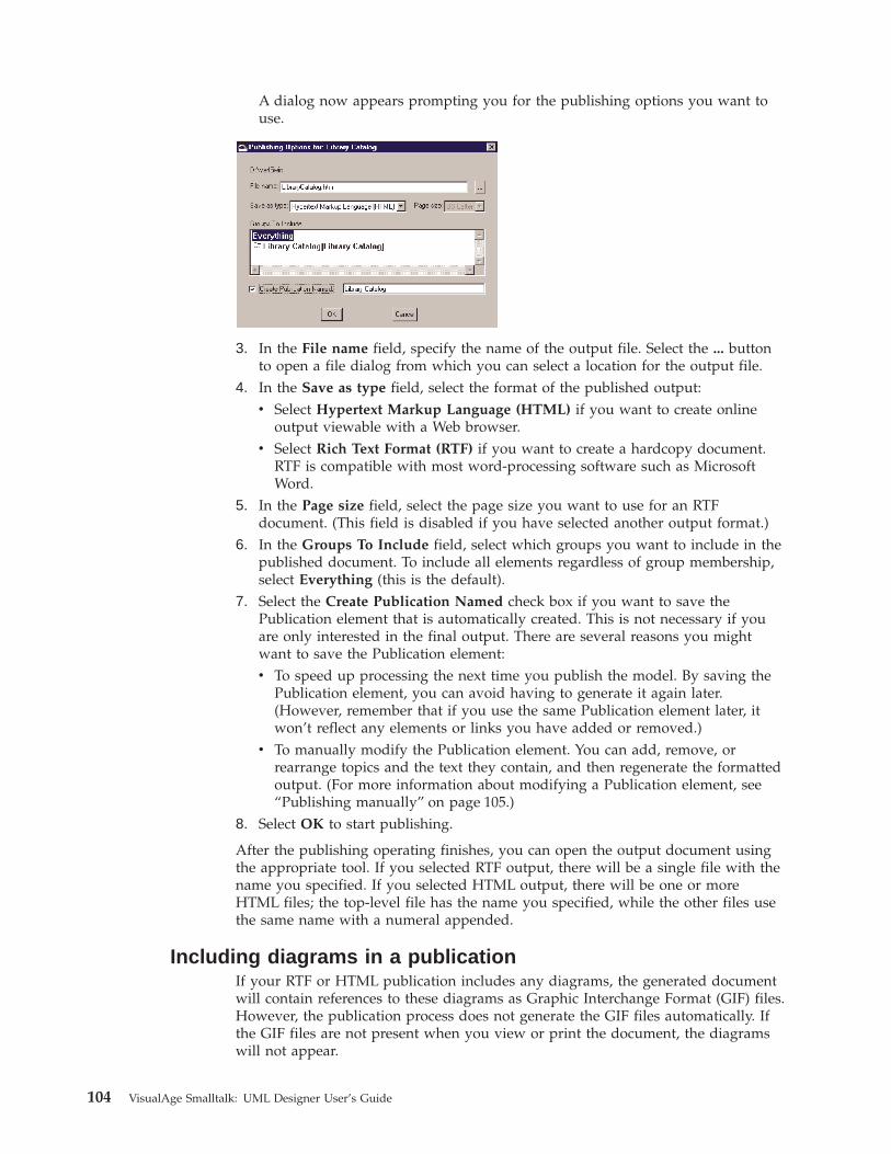
A dialog now appears prompting you for the publishing options you want touse.
3. In the File name field, specify the name of the output file. Select the ... buttonto open a file dialog from which you can select a location for the output file.
4. In the Save as type field, select the format of the published output:v Select Hypertext Markup Language (HTML) if you want to create online
output viewable with a Web browser.v Select Rich Text Format (RTF) if you want to create a hardcopy document.
RTF is compatible with most word-processing software such as MicrosoftWord.
5. In the Page size field, select the page size you want to use for an RTFdocument. (This field is disabled if you have selected another output format.)
6. In the Groups To Include field, select which groups you want to include in thepublished document. To include all elements regardless of group membership,select Everything (this is the default).
7. Select the Create Publication Named check box if you want to save thePublication element that is automatically created. This is not necessary if youare only interested in the final output. There are several reasons you mightwant to save the Publication element:v To speed up processing the next time you publish the model. By saving the
Publication element, you can avoid having to generate it again later.(However, remember that if you use the same Publication element later, itwon’t reflect any elements or links you have added or removed.)
v To manually modify the Publication element. You can add, remove, orrearrange topics and the text they contain, and then regenerate the formattedoutput. (For more information about modifying a Publication element, see“Publishing manually” on page 105.)
8. Select OK to start publishing.
After the publishing operating finishes, you can open the output document usingthe appropriate tool. If you selected RTF output, there will be a single file with thename you specified. If you selected HTML output, there will be one or moreHTML files; the top-level file has the name you specified, while the other files usethe same name with a numeral appended.
Including diagrams in a publicationIf your RTF or HTML publication includes any diagrams, the generated documentwill contain references to these diagrams as Graphic Interchange Format (GIF) files.However, the publication process does not generate the GIF files automatically. Ifthe GIF files are not present when you view or print the document, the diagramswill not appear.
104 VisualAge Smalltalk: UML Designer User’s Guide
To create a GIF file of a diagram, follow these steps:1. Open the diagram using the appropriate UML Designer diagrammer.2. Adjust the zooming and centering of the diagram so it appears in the
diagrammer exactly as you want it to appear in the published document.3. Select Save As GIF from the File menu.4. Accept the default generated file name for the GIF file (the published document
will use this name to refer to the diagram). Save the GIF file to the samedirectory that contains your published document.
If a diagram changes, you must repeat this process to update the GIF file. Becausethe graphics are stored in separate files, it is not necessary to repeat the publicationprocess if only the diagrams have changed.
Publishing manuallyIf you prefer to customize your document, you can manually build the Publicationelement from which the formatted output is generated. You can do this either bycreating a Publication element and adding topics to it one by one, or byautomatically generating a Publication element and then modifying it. (See“Publishing automatically” on page 103 for more information about automaticallygenerating a Publication element.)
Creating a Publication elementTo create a new, empty publication, follow these steps:1. In the Relationships Browser, select Publications in the list of relationships. (If
Publications doesn’t appear in the list, select the All Relationships filter.)2. Select New from the pop-up menu.3. When prompted, specify a name for the new Publication element.
The new Publication element appears in the list of elements.
Editing a Publication elementTo edit the contents of a Publication element, double-click on the element in theRelationships Browser. (You can do this with any Publication element, whethercreated manually or automatically.) A Focus browser opens showing you the
Chapter 15. Publishing models 105
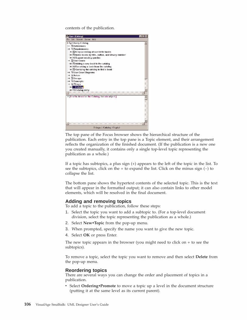
contents of the publication.
The top pane of the Focus browser shows the hierarchical structure of thepublication. Each entry in the top pane is a Topic element, and their arrangementreflects the organization of the finished document. (If the publication is a new oneyou created manually, it contains only a single top-level topic representing thepublication as a whole.)
If a topic has subtopics, a plus sign (+) appears to the left of the topic in the list. Tosee the subtopics, click on the + to expand the list. Click on the minus sign (−) tocollapse the list.
The bottom pane shows the hypertext contents of the selected topic. This is the textthat will appear in the formatted output; it can also contain links to other modelelements, which will be resolved in the final document.
Adding and removing topicsTo add a topic to the publication, follow these steps:1. Select the topic you want to add a subtopic to. (For a top-level document
division, select the topic representing the publication as a whole.)2. Select New→Topic from the pop-up menu.3. When prompted, specify the name you want to give the new topic.4. Select OK or press Enter.
The new topic appears in the browser (you might need to click on + to see thesubtopics).
To remove a topic, select the topic you want to remove and then select Delete fromthe pop-up menu.
Reordering topicsThere are several ways you can change the order and placement of topics in apublication.v Select Ordering→Promote to move a topic up a level in the document structure
(putting it at the same level as its current parent).
106 VisualAge Smalltalk: UML Designer User’s Guide
v Select Ordering→Demote to move a topic down a level in the documentstructure (making it a subtopic).
v Select Ordering→Up or Ordering→Down to change a topic’s place in thedocument by one position, without changing its level.
v Select Ordering→Reorder To to move a topic elsewhere in the publication. Awindow appears prompting you for the location you want to move the topic to.
Editing textTo add text to a topic, select the Topic element in the Focus browser and type thetext in the hypertext pane. Any text you enter will be included in the publisheddocument.
In addition, you can include links to model elements, which will cause them to beincluded in the publication. There are two kinds of links:v A reference link causes a reference to an element to appear in the published
topic. In an HTML document, the reference is a hypertext link to a separate topiccontaining the element text. (A reference link causes an additional topiccontaining the element text to be included automatically when published.)In an RTF document, a reference link causes the name of the element to appearin the topic text, and a separate topic containing the element text isautomatically included.Reference links are useful in situations where multiple topics refer to the sameelement. This can avoid unnecessary duplication of text, since all of the linkswill point to the same topic.
v An inline link causes the element’s text to be included directly in the topic text.
Generating outputOnce you have built your publication, you can use it to generate formatted outputjust as you would with any other model element.
To generate output from a publication, select the Publication element and thenselect Publish from the pop-up menu. For more information, see “Publishingautomatically” on page 103.
Chapter 15. Publishing models 107

108 VisualAge Smalltalk: UML Designer User’s Guide

Part 4. Appendixes
© Copyright IBM Corp. 1997, 2000 109

110 VisualAge Smalltalk: UML Designer User’s Guide
Index
Special Characters″backward″ development process 4, 13″forward″ development process 4, 13
phases 4
Aabstraction, levels of 4Action idiom 15activation 12, 52actor
adding figure to diagram 78creating element 71definition 9identifying in use case 71
Add idiom 20adornments 37
labels 41aggregation 50Align Horizontal menu choice 43Align To Grid menu choice 43Align Vertical menu choice 43alignment of diagram figures 43analysis model 4
model elements 10association
creating 90labeling 41ownership 41specifying constraints 50
attaching 87attaching node figures 38attribute
implemented 11specified 11type 84
Attribute Name Only menu choice 48Attributes field of relationship
properties 51
BBrowse Connections menu choice 28Browse Destinations menu choice 28Browse Editions menu choice 56browser levels 32
Advanced 34Basic 33Cross-reference 33General 33Meta 33
Browser settings 35browsers 27
levels 32refreshing 56spawning 28
Browsing inconsistencies 34
Ccapturing requirements 67Center menu choice 44
Check Consistency menu choice 34class design
adding figure to diagram 87definition 11retrieving from existing class 22, 97
class diagram 11building 87creating 87
Class diagrammer 47opening 87
class figurefiltering methods and attributes 48
code generation 89Java and Smalltalk conventions 17system settings 36
Color/Font settings 36composite objects 56composition 50Composition field of relationship
properties 50concept
creating element 75definition 9identifying in use case 74
condition 54configuration management 55conformance 10
showing on class diagram 88connector figure 37
adding 39adding with Hide/Show Relationships
menu choice 40copying from a model
relationship 40copying from another diagram 40general display properties 42
for class diagram connectors 49lamination 41manually creating 39
consistency, checking 34constraints 50crash recovery 56Cycles field of relationship properties 51
DDelete Check field of relationship
properties 51Delete Figure And Model menu
choice 43Delete Figure menu choice 43deleting figures 79design model 5
model elements 11Detailed Text menu choice 58diagram
class 11creating 38creating GIF file 45definition 7missing objects on 44overview 37
diagram (continued)panning and zooming 44printing 45refreshing 44sequence diagram 51synchronization 44use case 9
diagram element 7diagrammers 37
Class diagrammer 47Use case diagrammer 46using 38
Display Options menu choice 42Distribute By Centers menu choice 43Distribute By Edges menu choice 43
EEdit Condition menu choice 54Edit From menu choice 43Edit To menu choice 43Edition Browser 57editions 55
browsing 55loading 55reconciling differences 59text 75
Editions menu choice 56exception 10existing classes, modeling 95
Ffigure 37
alignment 43deleting 43display properties 42
Figure Properties menu choice 42, 43filtering 32
by browser level 32by task 32relationship filters 28
Filtering Options menu choice 48Fit To Window menu choice 44focusing 28fonts 36Format menu choice 43
GGeneral Message idiom 19General settings 36Getter idiom 20GIF file, creating 45, 104group 7, 46, 77
browsing 29
© Copyright IBM Corp. 1997, 2000 111
HHide All Labels menu choice 43Hide/Show Relationships menu
choice 39, 40, 46Hierarchical Change Browser 57, 58Hierarchy Browser
opening 31overview 31
hypertext link 71
IId field of relationship properties 50Identifier idiom 17idiom
and protocol generation 14message 18
Add 20General Message 19Getter 20Remove 21Setter 21
responsibility 14, 73Action 15Identifier 17Reference 15Value 16
immutable relationship 50Implementation field of relationship
properties 51inconsistencies
browsing 34finding 34repairing 35
instance 12, 52adding to instance diagram 52, 99
Is By Reference field of relationshipproperties 51
Is Derived field of relationshipproperties 51
Is Immutable field of relationshipproperties 50
Is Iterated menu choice 54Is Navigable field of relationship
properties 51Is Unique field of relationship
properties 50iteration 54iterative development 4
JJava 17
KKernel models 67
Llabel 41lamination 41Levels menu choice 32lifeline 52link 37, 69
link 37, 69 (continued)″satisfies″ 70
link labels 36Link Name field of relationship
properties 50Load Alternative menu choice 59
Mmain protocol 96Make Consistent By Deleting menu
choice 34Make Consistent By Repairing menu
choice 34Max Editions menu choice 58message specification 10
browsing 82defining manually 85generating 13, 81, 83
methodimplemented 11specified 11
method call 12adding to instance diagram 53, 100
method instance 12Method Name Only menu choice 48method return 12Min/Max field of relationship
properties 50missing objects 44model
creating 67definition 3, 7prerequisites 67semantic models 4
model elements 7analysis model 10common 7design model 11loading 56requirements model 8
Move To Back menu choice 42Move To Front menu choice 42moving method call figures 53multiplicity 50, 92Multiplicity menu choice 49
NName menu choice 49Name Only menu choice 47navigability 43Navigation menu choice 43Next Difference menu choice 59node figure 37
adding 38adding with Hide/Show Relationships
menu choice 39attaching 38copying from another diagram 39copying from model element 39general display properties 42
class figures 47manually creating 38
Oobjects, missing 44Ordering field of relationship
properties 51Overview menu choice 45ownership of associations 41
PPan/Zoom menu choice 45panning a diagram 44parameter 10
changing type 83participant 72
linking to 74protocol for 17
Path Browser 84opening 30overview 30
phases, development 4prerequisites 67printing diagrams 45protocol 4
adding figure to class diagram 88definition 10finding for participants 17generating 13, 81, 83main protocol 96mapping to thing 81retrieving from class design 22, 96using 81
publicationediting 105element 7generating 103
automatically 103manually 105
generating output 107GIF files for 45including diagrams 104
Publish menu choice 103publishing 103
Qqualifier 51
showing on class diagram 49
Rreconciling editions 59Reference idiom 15refinement 10
browsing 29Refresh Browser menu choice 44, 56relationship
browsing 28editing properties 49ownership 41
Relationships Browseropening 67overview 27
Remove From List menu choice 59Remove idiom 21Rename menu choice 42Repairing inconsistencies 35
112 VisualAge Smalltalk: UML Designer User’s Guide
requirementcapturing 67creating 68definition 8
requirements model 4model elements 8
Reset All Browsers menu choice 56Reset Pan/Zoom menu choice 44responsibility
creating element 73definition 9identifying in use case 72
retrieving protocol 96return value 10
changing type 85reverse engineering 4, 22, 95Role menu choice 43Role Name field of relationship
properties 50
SSave As Gif File menu choice 45scenario 9scope (method or attribute) 48semantic models 4sequence diagram
creating 99definition 12
Setter idiom 21Show All Labels menu choice 43Show From menu choice 43Show From Qualified Attributes menu
choice 49Show Groups option 29Show Model If Different menu choice 42Show Navigation Arrow menu
choice 43Show Refined By Button option 29Show Scope menu choice 48Show Stereotype From menu choice 49
Show Stereotype menu choice 42Show Stereotype To menu choice 49Show To menu choice 43Show To Qualified Attributes menu
choice 49Show Visibility menu choice 48Smalltalk 17stereotype 7Stereotype field of relationship
properties 50substitutability 81System figure 77System settings 35
TTasks menu choice 32team development 57text, revising 75Text field of relationship properties 50thing
creating element 72definition 9identifying in use case 72linking to 72mapping to protocol 81retrieving from protocol 23
topic 106traceability 70transforms 5, 12type 10type, attribute 84type, parameter 84type, return value 85
UUI settings 35UML Designer
development process supported 4evolutionary approach 4
UML Designer (continued)features 3integration with VisualAge for
Smalltalk 3introduction 3semantic models 4transforms 5
UML Stereotype field of relationshipproperties 50
Unified Modeling Language (UML) 4syntax 36
unique relationship 50use case
analyzing 70creating 69definition 8description 69
use case diagram 9creating 77
Use case diagrammer 46use case figure 78Use Figure Specific Name menu
choice 42Use Small Margins menu choice 47
VValue idiom 16version control 55Versions Only menu choice 58visibility (method or attribute) 48
Wwaterfall process 4
ZZoom Percentage menu choice 44zooming a diagram 44
Index 113