Embed Size (px)
DESCRIPTION
catalogo abb
Citation preview
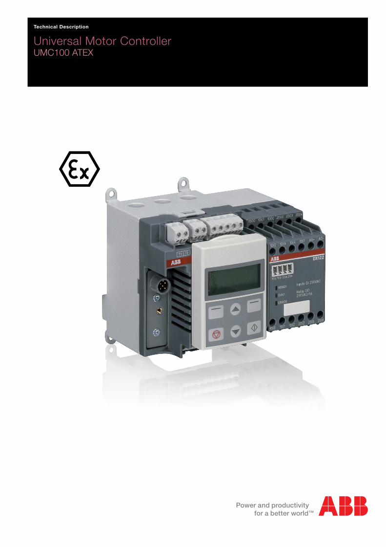
Technical Description
Universal Motor ControllerUMC100 ATEX
- 2 -UMC100-FBP
Universal Motor ControllerUMC100-FBPTechnical Description
FieldBusPlug / Issue: 01.2011
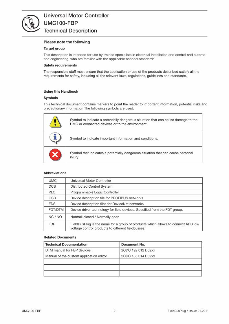
Please note the following
Target group
This description is intended for use by trained specialists in electrical installation and control and automa-tion engineering, who are familiar with the applicable national standards.
Safety requirements
The responsible staff must ensure that the application or use of the products described satisfy all the requirements for safety, including all the relevant laws, regulations, guidelines and standards.
Using this Handbook
Symbols
This technical document contains markers to point the reader to important information, potential risks and precautionary information The following symbols are used:
Symbol to indicate a potentially dangerous situation that can cause damage to the UMC or connected devices or to the environment
Symbol to indicate important information and conditions.
Symbol that indicates a potentially dangerous situation that can cause personal injury
Abbreviations
UMC Universal Motor Controller
DCS Distributed Control System
PLC Programmable Logic Controller
GSD Device description fi le for PROFIBUS networks
EDS Device description fi les for DeviceNet networks
FDT/DTM Device driver technology for fi eld devices. Specifi ed from the FDT group.
NC / NO Normall closed / Normally open
FBP FieldBusPlug is the name for a group of products which allows to connect ABB low voltage control products to different fi eldbusses.
Related Documents
Technical Documentation Document No.
DTM manual for FBP devices 2CDC 192 012 D02xx
Manual of the custom application editor 2CDC 15 014 D02xx
- - UMC100-FBP
Universal Motor ControllerUMC100-FBPTechnical Description
FieldBusPlug / Issue: 01.2011
Content
1 System Overview ...................................................................................................................................7
Function Overview ..............................................................................................................................7
Compatibility to UMC22 .....................................................................................................................8
Description of Components ................................................................................................................9
2 Installation ...........................................................................................................................................15
Assembly and Disassembly of UMC100-FBP and IO Modules .......................................................15
Connecting the IO Modules DX111 and DX122 ...............................................................................15
Wiring Inputs and Outputs ................................................................................................................16
Connecting Contactors.....................................................................................................................17
Motor Wiring .....................................................................................................................................19
Connecting External Current Transformers (CTs) .............................................................................20
Operation Details for Motors with Small Set Currents......................................................................21
Connecting the UMC100-PAN LCD Panel .......................................................................................22
Using the UMC100 in a PROFIBUS DP Network .............................................................................2
Using the UMC100 in a DeviceNet Network ....................................................................................24
Using the UMC100 in a CANopen Network .....................................................................................25
Using the UMC100 in a MODBUS RTU Network .............................................................................26
Usage in Draw-Out Systems ............................................................................................................27
Commissioning ....................................................................................................................................29
Commissioning Steps .......................................................................................................................29
Test Position .....................................................................................................................................1
4 Configuring the Motor Protection Functions .......................................................................................
Automatic Reset of Protection Faults ...............................................................................................
Long Start, Locked Rotor Protection ................................................................................................7
High Current Protection ....................................................................................................................8
Low Current Protection .....................................................................................................................9
Phase Loss Protection ......................................................................................................................40
Phase Imbalance Protection .............................................................................................................40
Phase Sequence Protection .............................................................................................................41
Motor Protection with Thermistor (PTC) acc. to EN 60947-8 (type A sensors) ................................41
Earth Fault Protection with CEM11 ..................................................................................................42
Voltage Dips, Load Shedding ...........................................................................................................4
5 Configuring the Motor Management Functions ..................................................................................47
Starting and Stopping the Motor ......................................................................................................47
Emergency Start ...............................................................................................................................52
Checkback Monitoring .....................................................................................................................5
Using the Digital UMC Inputs ...........................................................................................................5
- 4 -UMC100-FBP
Universal Motor ControllerUMC100-FBPTechnical Description
FieldBusPlug / Issue: 01.2011
Control Function Transparent ...........................................................................................................56
Control Function Overload Relay ......................................................................................................58
Control Function Direct Starter (DOL) ...............................................................................................60
Control Function Reversing Starter (REV).........................................................................................6
Control Function Star-Delta Starter ..................................................................................................66
Control Function Pole-Changing Starter ..........................................................................................69
Control Function Actuator 1 - 4 ........................................................................................................72
6 Configuring the Fieldbus Communication ...........................................................................................77
Setting the Bus Address ...................................................................................................................77
Address Check when using UMC in Motor Control Centres ............................................................77
Defining the Bus Fault Reaction .......................................................................................................78
Ignore Block Parameters ..................................................................................................................78
7 Using Expansion Modules ...................................................................................................................81
8 The LCD Control Panel UMC100-PAN ................................................................................................8
Overview ...........................................................................................................................................8
Monitoring Status Information ..........................................................................................................84
The Menu Tree ..................................................................................................................................84
Adjusting Parameters .......................................................................................................................90
Starting and Stopping the Motor ......................................................................................................92
9 Error Handling, Maintenance and Service ...........................................................................................95
Error Handling of the UMC ...............................................................................................................95
UMC100 Fault Indication ..................................................................................................................95
Fault Messages .................................................................................................................................95
Resetting Parameters to Factory Defaults .......................................................................................99
Resetting the Password ....................................................................................................................99
Reading and Resetting Maintenance Counters ................................................................................99
DX1xx Status Codes .......................................................................................................................100
Replacing a UMC100 ......................................................................................................................100
Replacing a DX1xx IO Module ........................................................................................................100
Requesting Support ........................................................................................................................100
10 Safety and Commissioning Notes for Motors in EEx Areas ............................................................101
Introduction .....................................................................................................................................101
Safe state ........................................................................................................................................101
Safety functions ..............................................................................................................................101
Configuring the safety functions .....................................................................................................102
Checking the configuration .............................................................................................................10
Protecting the parameters against unintentional changes .............................................................10
Maintenance and repair ..................................................................................................................104
Tests ................................................................................................................................................104
Configuration via fieldbus ...............................................................................................................104
Characteristic values according to IEC 61508 ...............................................................................104
Characteristic values according to ISO 1849 ...............................................................................104
- 5 - UMC100-FBP
Universal Motor ControllerUMC100-FBPTechnical Description
FieldBusPlug / Issue: 01.2011
A1 Parameters and Data Structures on a Fieldbus ..............................................................................105
Monitoring Data ..............................................................................................................................105
Command Data ..............................................................................................................................105
Accessing Data on PROFIBUS .......................................................................................................107
Accessing Data on Modbus ...........................................................................................................107
Accessing Data on DeviceNet ........................................................................................................107
Accessing Data on CANopen .........................................................................................................107
Parameter Organisation ..................................................................................................................108
Motor Management Parameters .....................................................................................................108
Protection Parameters ....................................................................................................................11
Communication Parameters ...........................................................................................................116
IO Module Parameters ....................................................................................................................116
UMC Display Parameters (5) ..........................................................................................................117
Function Block Related Parameters ...............................................................................................118
All Parameters Sorted by Parameter Number ................................................................................119
All Parameters Sorted Alphabetically .............................................................................................121
A2 Examples of Circuit Diagrams .........................................................................................................12
Direct Starter, Category 4 ...............................................................................................................12
Reversing Starter, Category 4 .........................................................................................................124
A Technical Data .................................................................................................................................125
UMC100 ..........................................................................................................................................125
Performance Data ...........................................................................................................................129
UMC100-PAN .................................................................................................................................10
DX111 and DX122 ..........................................................................................................................10
EMC UMC100 and DX1xx Modules ...............................................................................................1
Dimensions .....................................................................................................................................14
- 6 -UMC100-FBP
Universal Motor ControllerUMC100-FBPTechnical Description
FieldBusPlug / Issue: 01.2011
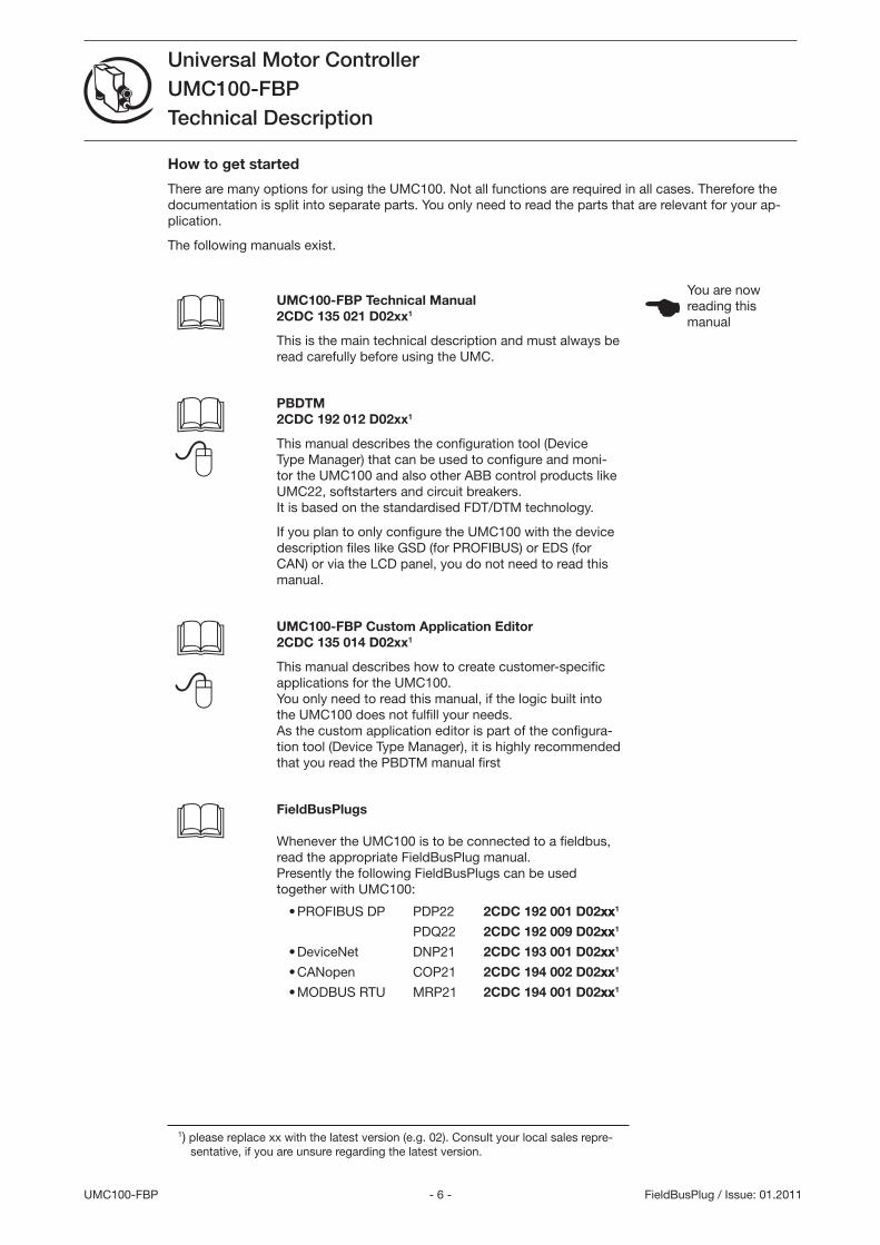
How to get started
There are many options for using the UMC100. Not all functions are required in all cases. Therefore the documentation is split into separate parts. You only need to read the parts that are relevant for your ap-plication.
The following manuals exist.
UMC100-FBP Technical Manual 2CDC 135 021 D02xx1
This is the main technical description and must always be read carefully before using the UMC.
PBDTM 2CDC 192 012 D02xx1
This manual describes the configuration tool (Device Type Manager) that can be used to configure and moni-tor the UMC100 and also other ABB control products like UMC22, softstarters and circuit breakers. It is based on the standardised FDT/DTM technology.
If you plan to only configure the UMC100 with the device description files like GSD (for PROFIBUS) or EDS (for CAN) or via the LCD panel, you do not need to read this manual.
UMC100-FBP Custom Application Editor 2CDC 135 014 D02xx1
This manual describes how to create customer-specific applications for the UMC100. You only need to read this manual, if the logic built into the UMC100 does not fulfill your needs. As the custom application editor is part of the configura-tion tool (Device Type Manager), it is highly recommended that you read the PBDTM manual first
FieldBusPlugs Whenever the UMC100 is to be connected to a fieldbus, read the appropriate FieldBusPlug manual. Presently the following FieldBusPlugs can be used together with UMC100:
PROFIBUS DP
DeviceNet
CANopen
MODBUS RTU
•
•
•
•
PDP22
PDQ22
DNP21
COP21
MRP21
2CDC 192 001 D02xxxx1
2CDC 192 009 D02xxxx1
2CDC 193 001 D02xxxx1
2CDC 194 002 D02xxxx1
2CDC 194 001 D02xxxx1
1) please replace xx with the latest version (e.g. 02). Consult your local sales repre-sentative, if you are unsure regarding the latest version.
You are now reading this manual
- 7 - UMC100-FBP ATEX
Universal Motor ControllerUMC100-FBP ATEXTechnical Description
V 6
FieldBusPlug / Issue: 01.2011
1 System OverviewThe Universal Motor Controller (UMC) is an intelligent motor controller for -phase AC induction motors combining the two classical functions of motor protection and motor management in a single device plus offering diagnostic and fieldbus communication. The device functions can be adjusted in a wide range to cover the needs of different industries. UMC100 is a further development of the UMC22.
Function Overview
Protection Functions
The UMC provides comprehensive motor protection including phase failure detection, adjustable motor protection for stalled motors during startup or normal operation, configurable current limits to generate trips or warnings and many more.
Overload classes 5, 10, 20, 0 and 40
Thermistor motor protection (PTC)
Earth fault detection when used in IT networks
One device type covers the whole current range starting from 0.24 up to 6 A. For higher currents up to 850 A additional current transformers are available.
Fieldbus Communication
The UMC100 can be integrated into different fieldbus networks such as PROFIBUS DP , DeviceNet, MODBUS and CANopen via the FieldBusPlug interface. All measured data, status signals and param-eters can be accessed via fieldbus.
It is also possible to use the UMC stand-alone (i.e. without FieldBusPlug).
The motor protection and motor management is fully functional in the event of a bus failure.
The fieldbus interface and the UMC can be separated. This offers many benefits in MCC applications especially for withdrawable systems.
Parameterisation of the protection and control functions can be carried out with the device description files as defined by the different fieldbuses (e.g. GSD for PROFIBUS). In addition a Device Type Manager (DTM) offering a very convenient device configuration via a laptop or within a control system is also available.
Motor Management, Inputs and Outputs
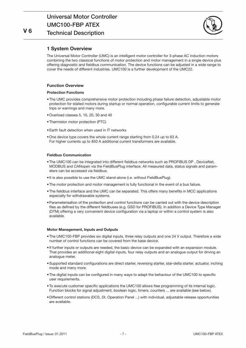
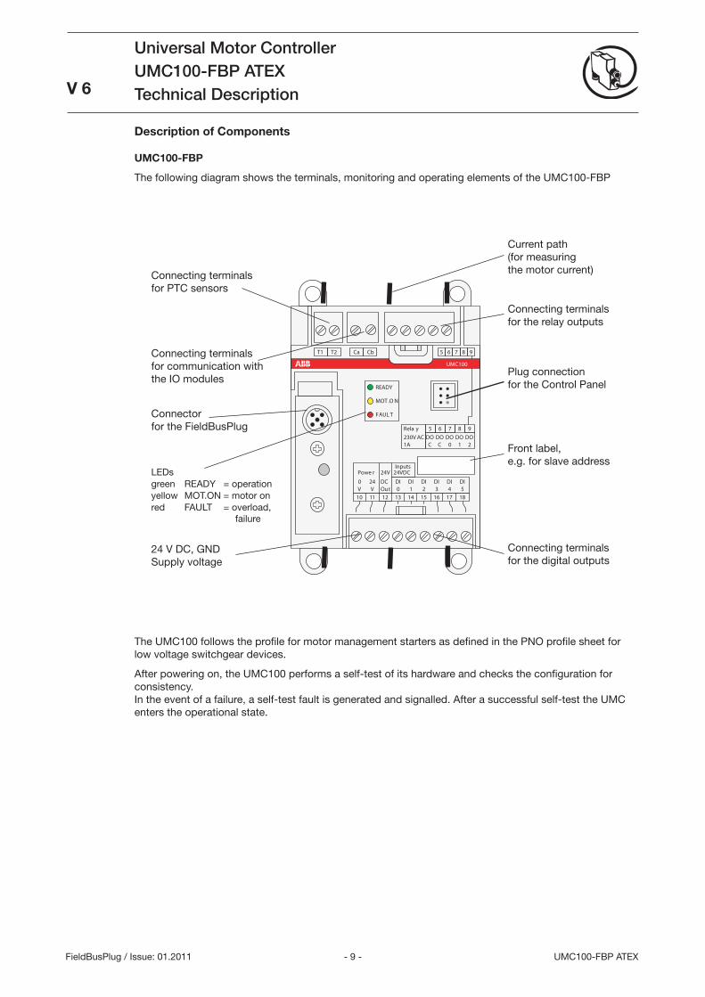
The UMC100-FBP provides six digital inputs, three relay outputs and one 24 V output. Therefore a wide number of control functions can be covered from the base device.
If further inputs or outputs are needed, the basic device can be expanded with an expansion module. That provides an additional eight digital inputs, four relay outputs and an analogue output for driving an analogue meter.
Supported standard configurations are direct starter, reversing starter, star-delta starter, actuator, inching mode and many more.
The digital inputs can be configured in many ways to adapt the behaviour of the UMC100 to specific user requirements.
To execute customer specific applications the UMC100 allows free programming of its internal logic. Function blocks for signal adjustment, boolean logic, timers, counters ... are available (see below).
Different control stations (DCS, DI, Operation Panel ...) with individual, adjustable release opportunities are available.
•
•
•
•
•
•
•
•
•
•
•
•
•
•
•
•
- 8 -UMC100-FBP ATEX
Universal Motor ControllerUMC100-FBPATEXTechnical Description V 6
FieldBusPlug / Issue: 01.2011
Metering, Monitoring and Diagnosis
Rapid, comprehensive diagnostics and operating status information is available on the UMC100 itself (LEDs), on the LCD panel (clear text messages), via fi eldbus or on a laptop connected directly or via bus to the UMC.
The fully graphic, multi-language LCD panel allows confi guration, control and monitoring of the UMC and its inputs and outputs.
Available diagnosis includes motor, bus and device status, maintenance counters such as number of starts and overload releases, remaining cooling time, etc.
Function Block Programming
The UMC100 has a set of predefi ned applications built in. These applications are built on the basis of function blocks and can be used directly without the need for a programming tool.
Custom applications can be created in a convenient way. The custom application editor is integrated in the PBDTM.
You can monitor an application online to support you during development and testing.
Control and protection related and general purpose function blocks are available: boolean logic, timers, counters, blocks representing the hardware, starter functions, ...
There are basic function blocks like boolean blocks that have no parameters. But there are also very powerful function blocks such as the multifunction inputs or the starter blocks. Such blocks have pa-rameters accessible via LCD and fi eldbus. By setting the block parameters you can adjust the behaviour of the blocks and the application to your needs.
Please note: It is not necessary to change the function block application if the pre-defi ned applications fulfi ll your requirements. But if you have specifi c requirements you can enable the customer application mode and adapt an existing application to your needs or even create your own one. This is described in the custom application editor manual (see section 'How to get started').
Compatibility to UMC22
Hardware
The UMC100 is mechanically compatible with the UMC22. The UMC100 does not need more space and can be used in all situations the UMC22 was used in. Please note that terminal 12 was previously a static 24 V output. It is now a switchable 24 V output that can signal a protection trip for example.
Fieldbus Interface
Both devices follow the PNO profi le for motor starters regarding their cyclic command and monitoring telegram. This means the fi rst two bytes within the cyclic telegrams are the same in both devices. But as the UMC100 provides many new functions, the command and monitoring telegrams are now longer, so that additional data can be transferred e.g. the status of the inputs of a connected expansion module.
To confi gure the new functions also the number and organisation of the parameters have changed.This means that the UMC100 looks different from a control system integration perspective.
It is not possible to just replace the UMC22 with a UMC100. Changes in the device integration packages are necessary.
•
•
•
•
•
•
•
•
- 9 - UMC100-FBP ATEX
Universal Motor ControllerUMC100-FBP ATEXTechnical Description
V 6
FieldBusPlug / Issue: 01.2011
181716151413121110
DIDIDIDIDIDI
24V
240543210OutVV
Powe r
T1
8DO1
7DO0
6DOC
5DOC
9DO2
8765 9T2 Ca Cb
UMC100
READY
MOT.ON
FAULT
Rela y230VAC1A
Inputs24VDC
DC
Connecting terminals for the relay outputs
Connecting terminals for PTC sensors
Current path (for measuring the motor current)
Connecting terminals for the digital outputs
Plug connection for the Control Panel
Connector for the FieldBusPlug
Front label, e.g. for slave address
24 V DC, GND Supply voltage
Connecting terminals for communication with the IO modules
The UMC100 follows the profile for motor management starters as defined in the PNO profile sheet for low voltage switchgear devices.
After powering on, the UMC100 performs a self-test of its hardware and checks the configuration for consistency. In the event of a failure, a self-test fault is generated and signalled. After a successful self-test the UMC enters the operational state.
Description of Components
UMC100-FBP
The following diagram shows the terminals, monitoring and operating elements of the UMC100-FBP
LEDsgreen READY = operationyellow MOT.ON = motor onred FAULT = overload,
failure
- 10 -UMC100-FBP ATEX
Universal Motor ControllerUMC100-FBPATEXTechnical Description
V 6
FieldBusPlug / Issue: 01.2011
C urrentM easurem ent
T herm alMotor Model
Outputs
P hase Loss,Imbalance
O ther Protection
F unctions
Predefined or User-Defined Function Block Model
T rip
U nit
C om m ands
(D I,
B U S ,
P anel)
S tart/S topLogic S tarter
F unction
M onitoring
(P anel,
B us)
P rotection
M otor Control
H ard w areS upervis ion
C heck backS upervis ion
Status Signals,Measured Values
PTC
Control FunctionRelevant Outputs
Application TripSignals Relay Out
T1T2
DI
DI0DI1DI2DI3DI4DI5
DI0
FBPInterface
UMC-PAN
24VDC
G N Dint. supply
DOCDO0DO1DO2
DO3
1Ca1Cb IO Bus
Ext. Earth FaultDI0-DI2
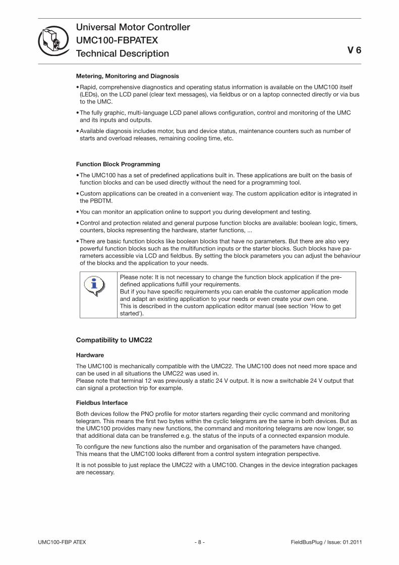
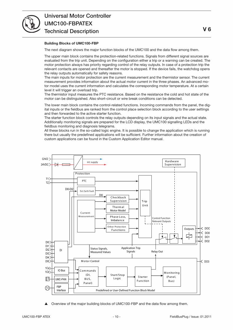
Overview of the major building blocks of UMC100-FBP and the data flow among them.
Building Blocks of UMC100-FBP
The next diagram shows the major function blocks of the UMC100 and the data flow among them.
The upper main block contains the protection-related functions. Signals from different signal sources are evaluated from the trip unit. Depending on the configuration either a trip or a warning can be created. The motor protection always has priority regarding control of the relay outputs. In case of a protection trip the relevant contacts are opened and thereafter the motor is stopped. If the device fails, the watchdog opens the relay outputs automatically for safety reasons. The main inputs for motor protection are the current measurement and the thermistor sensor. The current measurement provides information about the actual motor current in the three phases. An advanced mo-tor model uses the current information and calculates the corresponding motor temperature. At a certain level it will trigger an overload trip. The thermistor input measures the PTC resistance. Based on the resistance the cold and hot state of the motor can be distinguished. Also short-circuit or wire break conditions can be detected.
The lower main block contains the control-related functions. Incoming commands from the panel, the dig-ital inputs or the fieldbus are ranked from the control place selection block according to the user settings and then forwarded to the active starter function. The starter function block controls the relay outputs depending on its input signals and the actual state. Additionally monitoring signals are prepared for the LCD display, the UMC100 signalling LEDs and the fieldbus monitoring and diagnosis telegrams. All these blocks run in the so-called logic engine. It is possible to change the application which is running there but usually the predefined applications will be sufficient. Further information about the creation of custom applications can be found in the Custom Application Editor manual.
- 11 - UMC100-FBP ATEX
Universal Motor ControllerUMC100-FBP ATEXTechnical Description
V 6
FieldBusPlug / Issue: 01.2011
DX111
1C a 1C b 2C a 2C b
READY
Diag
ERROR
Inputs D I 24V DC
R elay D O230V AC / 1A
0V 24V DC
1DI0 1DI1 1DIZ
1DI2 1DI3 1DI4
1DO0 1DO1 1DOC
2DIZ 2DI5 2DI6
2DI7 AO+ AO-
2DOC 2DO2 2DO3
DX122
1C a 1C b 2C a 2C b
READY
Diag
ERROR
Inputs D I 230V AC
R elay D O230V AC / 1A
0V 24V DC
1DI0 1DI 1DIZ1
1DI2 1DI3 1DI4
1DO0 1DO1 1DOC
2DIZ 2DI5 2DI6
2DI7 AO+ AO-
2DOC 2DO2 2DO3
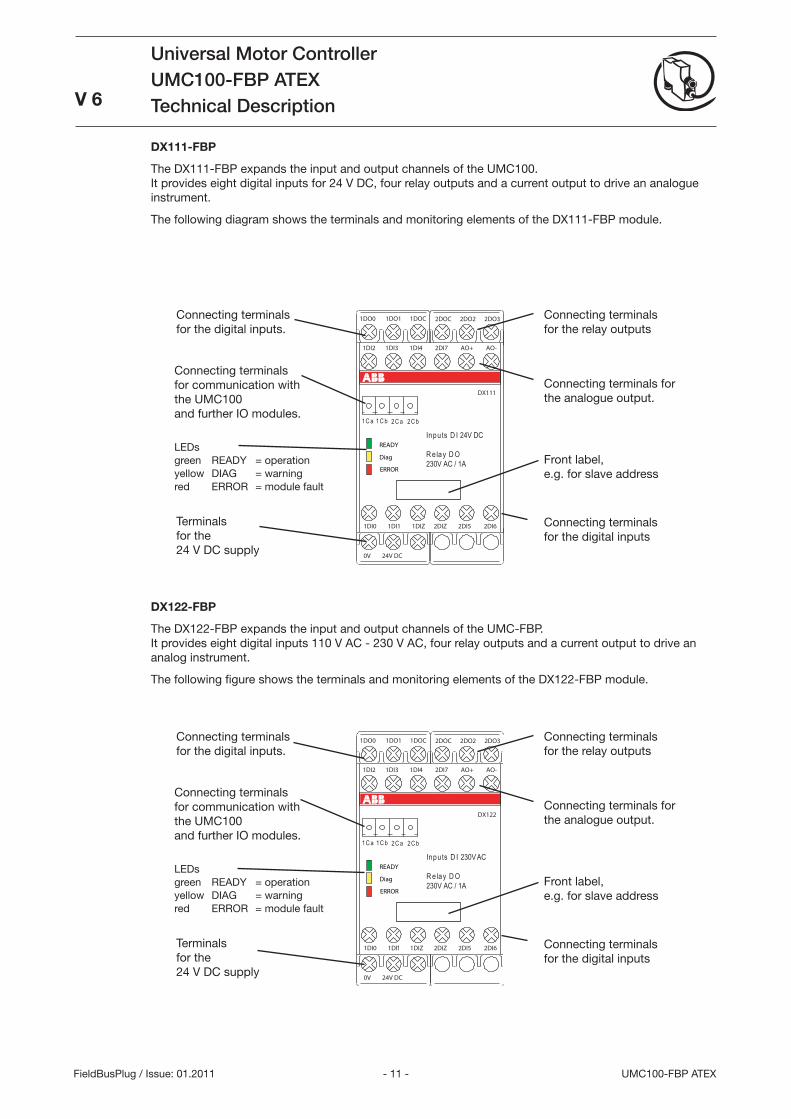
DX111-FBP
The DX111-FBP expands the input and output channels of the UMC100. It provides eight digital inputs for 24 V DC, four relay outputs and a current output to drive an analogue instrument.
The following diagram shows the terminals and monitoring elements of the DX111-FBP module.
DX122-FBP
The DX122-FBP expands the input and output channels of the UMC-FBP. It provides eight digital inputs 110 V AC - 20 V AC, four relay outputs and a current output to drive an analog instrument.
The following figure shows the terminals and monitoring elements of the DX122-FBP module.
Connecting terminals for the digital inputs
Connecting terminals for the analogue output.
Connecting terminals for the relay outputs
Front label, e.g. for slave address
Terminals for the 24 V DC supply
Connecting terminals for communication with the UMC100 and further IO modules.
Connecting terminals for the digital inputs.
LEDsgreen READY = operationyellow DIAG = warningred ERROR = module fault
Terminals for the 24 V DC supply
Connecting terminals for communication with the UMC100 and further IO modules.
Connecting terminals for the digital inputs.
LEDsgreen READY = operationyellow DIAG = warningred ERROR = module fault
Connecting terminals for the digital inputs
Connecting terminals for the analogue output.
Connecting terminals for the relay outputs
Front label, e.g. for slave address
- 12 -UMC100-FBP ATEX
Universal Motor ControllerUMC100-FBPATEXTechnical Description
V 6
FieldBusPlug / Issue: 01.2011
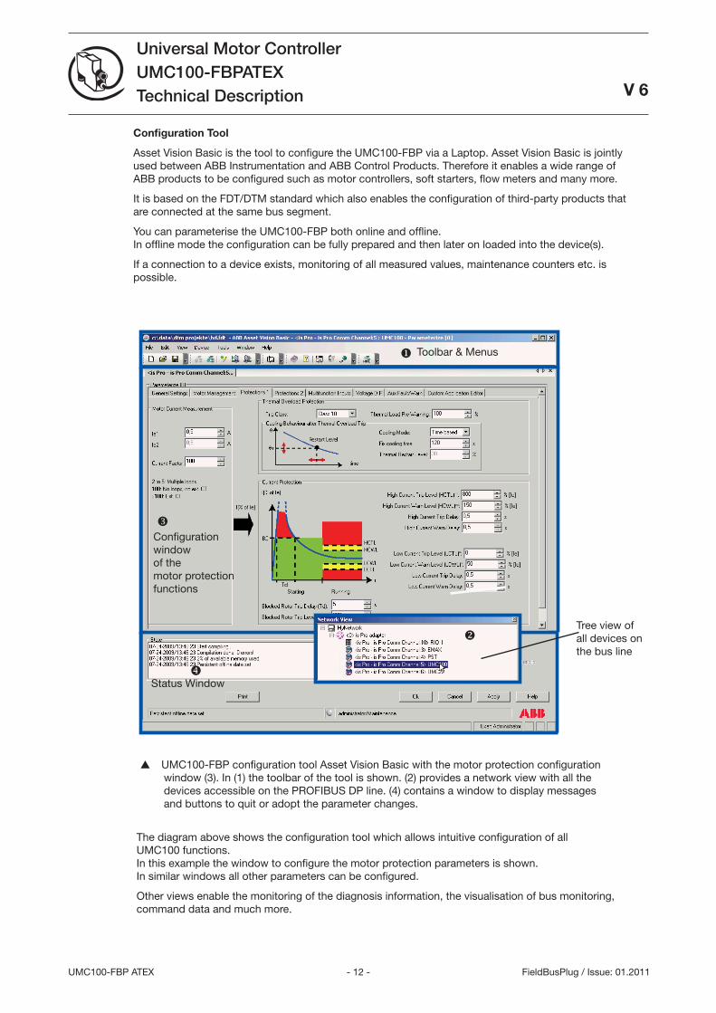
Configuration Tool
Asset Vision Basic is the tool to configure the UMC100-FBP via a Laptop. Asset Vision Basic is jointly used between ABB Instrumentation and ABB Control Products. Therefore it enables a wide range of ABB products to be configured such as motor controllers, soft starters, flow meters and many more.
It is based on the FDT/DTM standard which also enables the configuration of third-party products that are connected at the same bus segment.
You can parameterise the UMC100-FBP both online and offline. In offline mode the configuration can be fully prepared and then later on loaded into the device(s).
If a connection to a device exists, monitoring of all measured values, maintenance counters etc. is possible.
Tree view of all devices on the bus line
Toolbar & Menus
Status Window
The diagram above shows the configuration tool which allows intuitive configuration of all UMC100 functions. In this example the window to configure the motor protection parameters is shown. In similar windows all other parameters can be configured.
Other views enable the monitoring of the diagnosis information, the visualisation of bus monitoring, command data and much more.
UMC100-FBP configuration tool Asset Vision Basic with the motor protection configuration window (). In (1) the toolbar of the tool is shown. (2) provides a network view with all the devices accessible on the PROFIBUS DP line. (4) contains a window to display messages and buttons to quit or adopt the parameter changes.
Configuration window of the motor protection functions
- 1 - UMC100-FBP ATEX
Universal Motor ControllerUMC100-FBP ATEXTechnical Description
V 6
FieldBusPlug / Issue: 01.2011
2CD
C
42 01
5F00
09
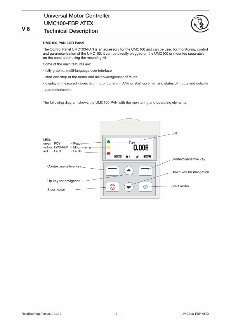
UMC100-PAN LCD Panel
The Control Panel UMC100-PAN is an accessory for the UMC100 and can be used for monitoring, control and parameterisation of the UMC100. It can be directly plugged on the UMC100 or mounted separately on the panel door using the mounting kit.
Some of the main features are:
- fully graphic, multi-language user interface
- start and stop of the motor and acknowledgement of faults.
- display of measured values (e.g. motor current in A/% or start-up time) and status of inputs and outputs
- parameterisation
The following diagram shows the UMC100-PAN with the monitoring and operating elements:
Context-sensitive key
Up key for navigation
Down key for navigation
Context-sensitive key
Start motorStop motor
LCD
LEDsgreen RDY = Readyyellow FWD/REV = Motor runingred Fault = Faults
- 14 -UMC100-FBP ATEX
Universal Motor ControllerUMC100-FBPATEXTechnical Description
V 6
FieldBusPlug / Issue: 01.2011
- 15 - UMC100-FBP ATEX
Universal Motor ControllerUMC100-FBP ATEXTechnical DescriptionV 6
FieldBusPlug / Issue: 01.2011
181716151413121110
DIDIDIDIDIDI
24V
240543210OutVV
Power
T1
8
DO1
7
DO0
6
DOC
5
DOC
9
DO2
8765 9T2 Ca Cb
UMC100
READY
MOT.ON
FAULT
Relay
230VAC1A
Inputs24VDC
DC
2CD
C25
2281
F000
5.ep
s
2CD
C25
2282
F000
5.ep
s
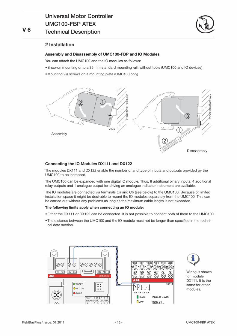
Wiring is shown for module DX111. It is the same for other modules.
Assembly
Disassembly
Connecting the IO Modules DX111 and DX122
The modules DX111 and DX122 enable the number of and type of inputs and outputs provided by the UMC100 to be increased.
The UMC100 can be expanded with one digital IO module. Thus, 8 additional binary inputs, 4 additional relay outputs and 1 analogue output for driving an analogue indicator instrument are available.
The IO modules are connected via terminals Ca and Cb (see below) to the UMC100. Because of limited installation space it might be desirable to mount the IO modules separately from the UMC100. This can be carried out without any problems as long as the maximum cable length is not exceeded.
The following limits apply when connecting an IO module:
Either the DX111 or DX122 can be connected. It is not possible to connect both of them to the UMC100.
The distance between the UMC100 and the IO module must not be longer than specifi ed in the techni-cal data section.
•
•
2 Installation
Assembly and Disassembly of UMC100-FBP and IO Modules
You can attach the UMC100 and the IO modules as follows:
Snap-on mounting onto a 5 mm standard mounting rail, without tools (UMC100 and IO devices)
Mounting via screws on a mounting plate (UMC100 only)
•
•
- 16 -UMC100-FBP ATEX
Universal Motor ControllerUMC100-FBP ATEXTechnical Description
V 6
FieldBusPlug / Issue: 01.2011
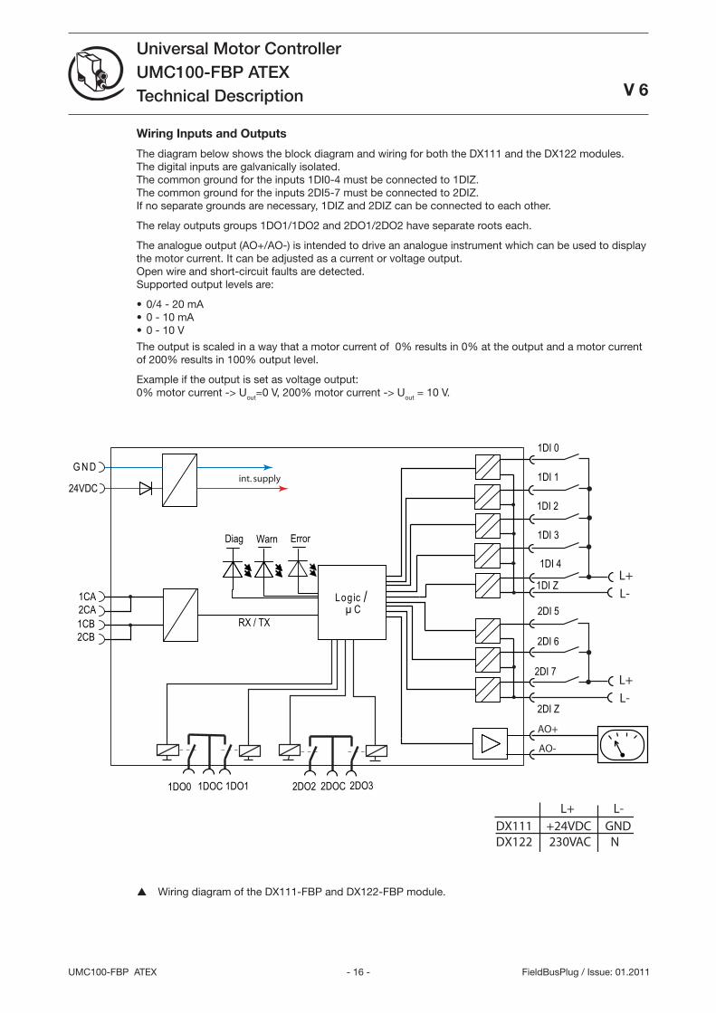
Wiring Inputs and Outputs
The diagram below shows the block diagram and wiring for both the DX111 and the DX122 modules. The digital inputs are galvanically isolated. The common ground for the inputs 1DI0-4 must be connected to 1DIZ. The common ground for the inputs 2DI5-7 must be connected to 2DIZ. If no separate grounds are necessary, 1DIZ and 2DIZ can be connected to each other.
The relay outputs groups 1DO1/1DO2 and 2DO1/2DO2 have separate roots each.
The analogue output (AO+/AO-) is intended to drive an analogue instrument which can be used to display the motor current. It can be adjusted as a current or voltage output. Open wire and short-circuit faults are detected. Supported output levels are:
0/4 - 20 mA 0 - 10 mA 0 - 10 V
The output is scaled in a way that a motor current of 0% results in 0% at the output and a motor current of 200% results in 100% output level.
Example if the output is set as voltage output: 0% motor current -> Uout=0 V, 200% motor current -> Uout = 10 V.
•••
Wiring diagram of the DX111-FBP and DX122-FBP module.
Log ic / µ C
24VDC
WarnDiag
G N D
AO+
Error
int. supply
1DI 0
1DI 1
1DI 2
1DI 3
1DI 4
2DI 6
2DI 7
2DI Z
1DOC1DO0 1DO1 2DOC2DO2 2DO3
RX / TX
1CA2CA1CB2CB
AO-
2DI 5
1DI ZL+
L-
L+
L-
DX111 +24VDC GNDDX122 230VAC N
L+ L-
- 17 - UMC100-FBP ATEX
Universal Motor ControllerUMC100-FBP ATEXTechnical DescriptionV 6
FieldBusPlug / Issue: 01.2011
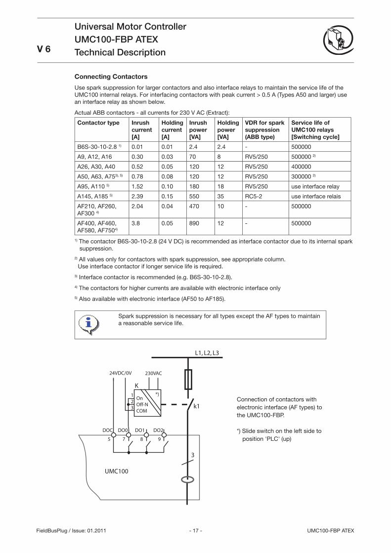
Connecting Contactors
Use spark suppression for larger contactors and also interface relays to maintain the service life of the UMC100 internal relays. For interfacing contactors with peak current > 0.5 A (Types A50 and larger) use an interface relay as shown below.
Actual ABB contactors - all currents for 20 V AC (Extract):
Contactor type Inrush current [A]
Holding current [A]
Inrush power [VA]
Holding power [VA]
VDR for spark suppression (ABB type)
Service life of UMC100 relays [Switching cycle]
B6S-0-10-2.8 1) 0.01 0.01 2.4 2.4 - 500000
A9, A12, A16 0.0 0.0 70 8 RV5/250 500000 2)
A26, A0, A40 0.52 0.05 120 12 RV5/250 400000
A50, A6, A75), 5) 0.78 0.08 120 12 RV5/250 00000 2)
A95, A110 5) 1.52 0.10 180 18 RV5/250 use interface relay
A145, A185 5) 2.9 0.15 550 5 RC5-2 use interface relais
AF210, AF260, AF00 4)
2.04 0.04 470 10 - 500000
AF400, AF460, AF580, AF7504)
.8 0.05 890 12 - 500000
1) The contactor B6S-0-10-2.8 (24 V DC) is recommended as interface contactor due to its internal spark suppression.
2) All values only for contactors with spark suppression, see appropriate column. Use interface contactor if longer service life is required.
) Interface contactor is recommended (e.g. B6S-0-10-2.8).
4) The contactors for higher currents are available with electronic interface only
5) Also available with electronic interface (AF50 to AF185).
Spark suppression is necessary for all types except the AF types to maintain a reasonable service life.
L1, L2, L3
3
24VDC/0V
K
k1
DOC DO0 DO1 DO2
5 7 8 9
UMC100
OnOff-NCOM
230VAC
123
*)Connection of contactors with electronic interface (AF types) to the UMC100-FBP.
*) Slide switch on the left side to position 'PLC' (up)
- 18 -UMC100-FBP ATEX
Universal Motor ControllerUMC100-FBP ATEXTechnical Description
V 6
FieldBusPlug / Issue: 01.2011
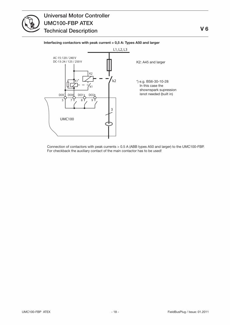
Interfacing contactors with peak current > 0,5 A: Types A50 and larger
L1, L2, L3
3
AC-15: 120 / 240 VDC-13: 24 / 125 / 250 V
k2
DOC DO0 DO1 DO2
5 7 8 9
UMC100
K1
K2
k1
*
Connection of contactors with peak currents > 0.5 A (ABB types A50 and larger) to the UMC100-FBP. For checkback the auxiliary contact of the main contactor has to be used!
*) e.g. BS6-0-10-28 In this case the shownspark supression isnot needed (built in)
K2: A45 and larger
- 19 - UMC100-FBP ATEX
Universal Motor ControllerUMC100-FBP ATEXTechnical Description
V 6
FieldBusPlug / Issue: 01.2011
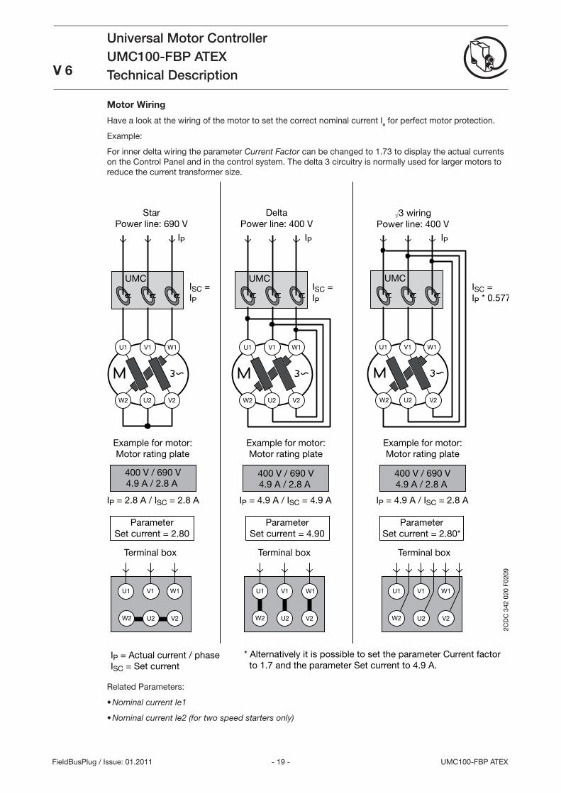
Motor Wiring
Have a look at the wiring of the motor to set the correct nominal current Ie for perfect motor protection.
Example:
For inner delta wiring the parameter Current Factor can be changed to 1.7 to display the actual currents on the Control Panel and in the control system. The delta circuitry is normally used for larger motors to reduce the current transformer size.
U2 W2 V2
V1 W1 U1
UMC
U2 W2 V2
V1 W1 U1
400 V / 690 V
W2
U1
U2
V1 W1
V2
UMC
U2 W2 V2
V1 W1 U1
400 V / 690 V
V1 W1 U1
W2 U2 V2
UMC
U2 W2 V2
V1 W1 U1
400 V / 690 V
Star Power line: 690 V
Delta Power line: 400 V
3 wiring Power line: 400 V
Example for motor: Motor rating plate
Example for motor: Motor rating plate
Example for motor: Motor rating plate
4.9 A / 2.8 A 4.9 A / 2.8 A 4.9 A / 2.8 A
Parameter Set current = 2.80
Parameter Set current = 4.90
Parameter Set current = 2.80*
Terminal box Terminal box Terminal box
IP = 2.8 A / ISC = 2.8 A IP = 4.9 A / ISC = 4.9 A IP = 4.9 A / ISC = 2.8 A
ISC = IP
ISC = IP
ISC = IP * 0.577
IP IP IP
2CD
C 3
42 0
20 F
0209
IP = Actual current / phase ISC = Set current
* Alternatively it is possible to set the parameter Current factor to 1.7 and the parameter Set current to 4.9 A.
Related Parameters:
Nominal current Ie1
Nominal current Ie2 (for two speed starters only)
•
•
- 20 -UMC100-FBP ATEX
Universal Motor ControllerUMC100-FBP ATEXTechnical Description V 6
FieldBusPlug / Issue: 01.2011
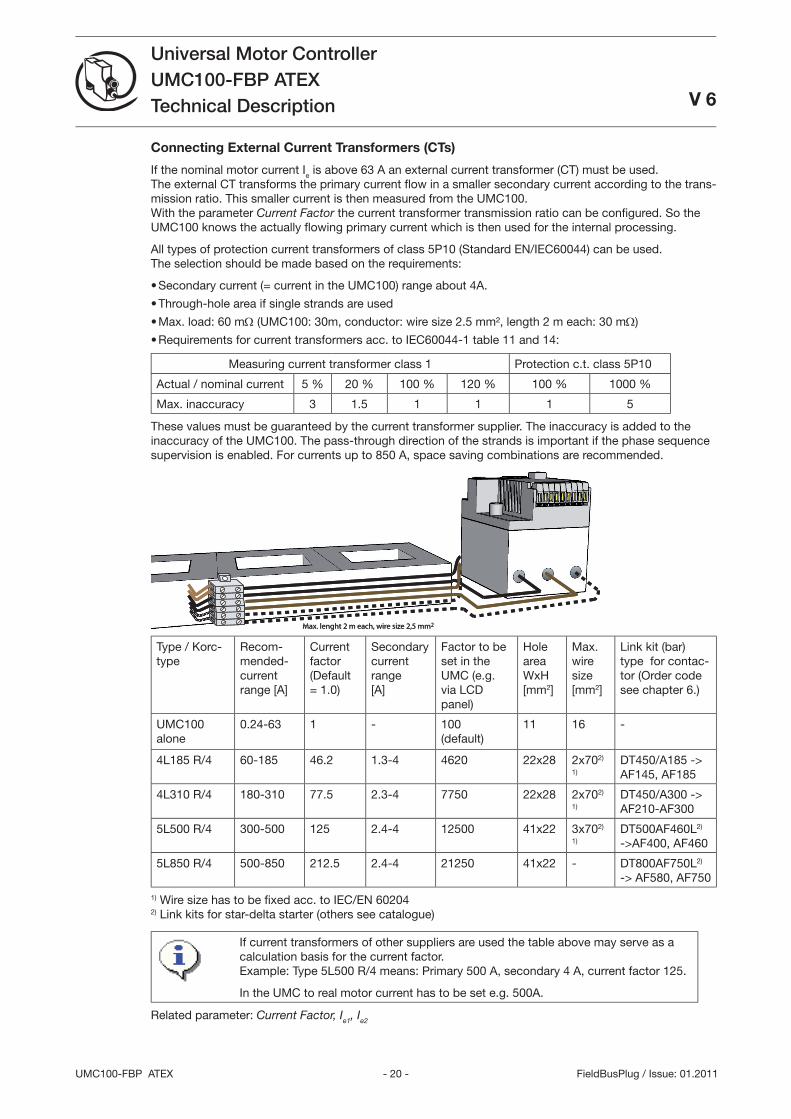
Connecting External Current Transformers (CTs)
If the nominal motor current Ie is above 6 A an external current transformer (CT) must be used. The external CT transforms the primary current fl ow in a smaller secondary current according to the trans-mission ratio. This smaller current is then measured from the UMC100. With the parameter Current Factor the current transformer transmission ratio can be confi gured. So the UMC100 knows the actually fl owing primary current which is then used for the internal processing.
All types of protection current transformers of class 5P10 (Standard EN/IEC60044) can be used. The selection should be made based on the requirements:
Secondary current (= current in the UMC100) range about 4A.
Through-hole area if single strands are used
Max. load: 60 mΩ (UMC100: 0m , conductor: wire size 2.5 mm², length 2 m each: 0 mΩ)
Requirements for current transformers acc. to IEC60044-1 table 11 and 14:
Measuring current transformer class 1 Protection c.t. class 5P10
Actual / nominal current 5 % 20 % 100 % 120 % 100 % 1000 %
Max. inaccuracy 1.5 1 1 1 5
These values must be guaranteed by the current transformer supplier. The inaccuracy is added to the inaccuracy of the UMC100. The pass-through direction of the strands is important if the phase sequence supervision is enabled. For currents up to 850 A, space saving combinations are recommended.
max. lenght 2 m each, wire size 2,5 mm2Max. lenght 2 m each, wire size 2,5 mm2
Type / Korc-type
Recom-mended-current range [A]
Current factor (Default = 1.0)
Secondary current range [A]
Factor to be set in the UMC (e.g. via LCD panel)
Hole area WxH [mm2]
Max. wire size [mm2]
Link kit (bar) type for contac-tor (Order code see chapter 6.)
UMC100 alone
0.24-6 1 - 100 (default)
11 16 -
4L185 R/4 60-185 46.2 1.-4 4620 22x28 2x702)
1)
DT450/A185 -> AF145, AF185
4L10 R/4 180-10 77.5 2.-4 7750 22x28 2x702)
1)
DT450/A00 -> AF210-AF00
5L500 R/4 00-500 125 2.4-4 12500 41x22 x702)
1)
DT500AF460L2) ->AF400, AF460
5L850 R/4 500-850 212.5 2.4-4 21250 41x22 - DT800AF750L2) -> AF580, AF750
1) Wire size has to be fi xed acc. to IEC/EN 60204 2) Link kits for star-delta starter (others see catalogue)
If current transformers of other suppliers are used the table above may serve as a calculation basis for the current factor. Example: Type 5L500 R/4 means: Primary 500 A, secondary 4 A, current factor 125.
In the UMC to real motor current has to be set e.g. 500A.
Related parameter: Current Factor, Ie1, Ie2
•
•
•
•
- 21 - UMC100-FBP ATEX
Universal Motor ControllerUMC100-FBP ATEXTechnical DescriptionV 6
FieldBusPlug / Issue: 01.2011
Operation Details for Motors with Small Set Currents
When using a UMC100-FBP in an environment with very strong magnetic fi elds and a small set current at the same time, the current measurement can deviate a few percent from the real current. Therefore the displayed motor current is too high and an overload trip occurs too early.
Very strong magnetic fi elds can originate from a contactor directly mounted beside the UMC100, closely passing current links or stray fi elds caused by large transform-ers. When observing the effect, the distance between the UMC100 and the contac-tor shall be increased to about 5 cm or the UMC100 shall be rotated by 90 degrees or the motor wires shall be looped through the UMC100 two to fi ve times.
When looping the motor wires multiple times, the parameter Current Factor must be adjusted according the number of loops. I.e. the parameter must be set to two if the wires are looped through the UMC100 two times. Two to fi ve loops are supported. The displayed current and the current transmitted over the fi eldbus are automatically corrected by the UMC100.
Please note that the adaptation of the current factor for √ circuits and multiple loops through the UMC100 are not possible at the same time.
Via fi eldbus also higher values than fi ve e.g. six can be set. The UMC100 ignores such values and creates a parameter fault. Values above 100 are possible and used in combination with external current transformers (see previous page).
Related parameters:
Current Factor•
- 22 -UMC100-FBP ATEX
Universal Motor ControllerUMC100-FBP ATEXTechnical Description V 6
FieldBusPlug / Issue: 01.2011
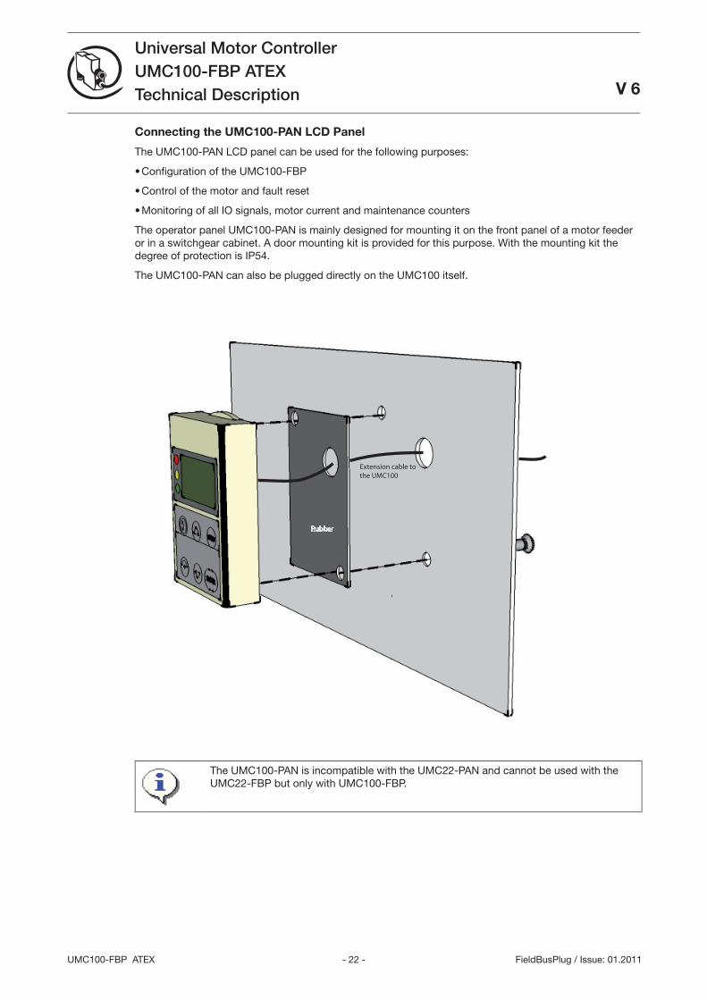
Connecting the UMC100-PAN LCD Panel
The UMC100-PAN LCD panel can be used for the following purposes:
Confi guration of the UMC100-FBP
Control of the motor and fault reset
Monitoring of all IO signals, motor current and maintenance counters
The operator panel UMC100-PAN is mainly designed for mounting it on the front panel of a motor feeder or in a switchgear cabinet. A door mounting kit is provided for this purpose. With the mounting kit the degree of protection is IP54.
The UMC100-PAN can also be plugged directly on the UMC100 itself.
Extension cable tothe UMC100
The UMC100-PAN is incompatible with the UMC22-PAN and cannot be used with the UMC22-FBP but only with UMC100-FBP.
•
•
•
- 2 - UMC100-FBP ATEX
Universal Motor ControllerUMC100-FBP ATEXTechnical DescriptionV 6
FieldBusPlug / Issue: 01.2011
Using the UMC100 in a PROFIBUS DP Network
PROFIBUS DP is at present one of the most common fi eldbus for industrial applications worldwide and is standardised in IEC61158 together with other fi eldbus protocols. The PROFIBUS DP standard has de-fi ned different network topologies. The most commonly used one is the ‘Party Line’ topology where one device is connected after the other.
PROFIBUS DP has evolved over time. The fi rst services offered by PROFIBUS DP are the so-called V0 services. They defi ne block parameterisation, confi guration, cyclic data exchange and diagnosis informa-tion exchange. DP-V0 only allows the complete parameter set to be written in one block. The bus master sends the parameter block to the slave during powering up of the slave/device. Some control systems also allow the sending the parameter block during normal operation.
Later the PROFIBUS DP-V1 specifi cation introduced new acyclic read/write services within the con-text of the PROFIBUS DP-V1 expansions. These acyclic services are inserted into special telegrams during ongoing cyclical bus operation and thus ensure compatibility between PROFIBUS DP-V0 and PROFIBUS DP-V1.
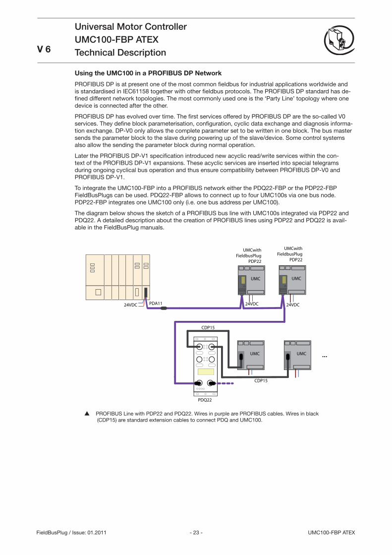
To integrate the UMC100-FBP into a PROFIBUS network either the PDQ22-FBP or the PDP22-FBP FieldBusPlugs can be used. PDQ22-FBP allows to connect up to four UMC100s via one bus node. PDP22-FBP integrates one UMC100 only (i.e. one bus address per UMC100).
The diagram below shows the sketch of a PROFIBUS bus line with UMC100s integrated via PDP22 and PDQ22. A detailed description about the creation of PROFIBUS lines using PDP22 and PDQ22 is avail-able in the FieldBusPlug manuals.
UMC
24VDC
UMC
24VDC
UMCwithFieldbusPlug
PDP22
24VDC PDA11
UMCwithFieldbusPlug
PDP22
PDQ22
UMC UMC ...
CDP15
CDP15
PROFIBUS Line with PDP22 and PDQ22. Wires in purple are PROFIBUS cables. Wires in black (CDP15) are standard extension cables to connect PDQ and UMC100.
- 24 -UMC100-FBP ATEX
Universal Motor ControllerUMC100-FBP ATEXTechnical Description V 6
FieldBusPlug / Issue: 01.2011
Integration with the GSD File
Besides the physical connection of a device to a PROFIBUS line, the engineering of the whole PROFIBUS system in the PROFIBUS master is necessary. Every modern PLC (Programmable Logic Controller) or DCS (Distributed Control System), that can be used as PROFIBUS master, offer the possibility to confi g-ure and parameterise devices connected to the master.
Electronic data sheets are used as a basis. In the PROFIBUS world these electronic data sheets are called GSD fi les. Within such a fi le all properties relevant for operation of the slave are described (e.g. supported baud rates, max. number of modules etc.).
The GSD fi le ABB_0A09.GSD (for PDQ22) and ABB_4E0.GSD (for PDP22) are contained in the software Engineering Package
PBE91-FBP.010x 1SAJ924091R010x.ZIP
The ZIP fi le can be obtained from ABB’s web site (http://www.abb.de -> Control Products and Systems) or on the FBP System CD (2CDC 190 008 E04xx). Please ask your local sales offi ce for it.
The UMC100 can be parameterised using the GSD fi le. But due to parameter length limitations only the most important parameters can be confi gured with the GSD fi le in the event that the PDQ22 is used. For PDP22 this limitation does not exist.
Integration with the Device Type Manager (DTM)
In addition to the option of integrating devices with GSD fi les more and more modern control systems support the FDT/DTM concept. FDT (Field Device Tool) technology standardises the communication inter-face between fi eld devices and systems.
For the UMC100 (and also other FBP devices) a DTM is available which can be ordered separately. Con-sult the PBDTM manual for more information.
For creating a customer-specifi c application the DTM must be used! Parameterisa-tion of the control and protection parameters can also be carried out with the GSD fi le only.
Using the UMC100 in a DeviceNet Network
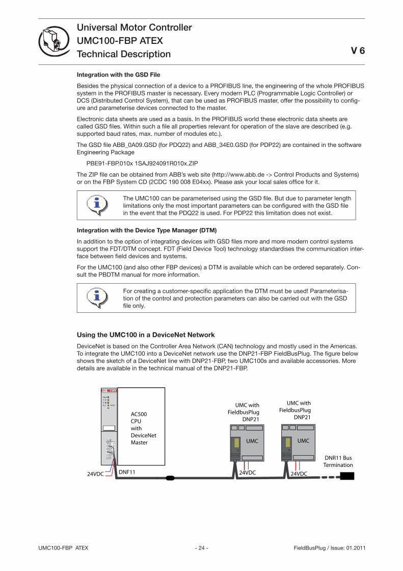
DeviceNet is based on the Controller Area Network (CAN) technology and mostly used in the Americas. To integrate the UMC100 into a DeviceNet network use the DNP21-FBP FieldBusPlug. The fi gure below shows the sketch of a DeviceNet line with DNP21-FBP, two UMC100s and available accessories. More details are available in the technical manual of the DNP21-FBP.
UMC
24VDC
UMC
24VDC
UMC withFieldbusPlug
DNP21
24VDC DNF11
UMC withFieldbusPlug
DNP21AC500CPUwithDeviceNetMaster
DNR11 Bus Termination
- 25 - UMC100-FBP ATEX
Universal Motor ControllerUMC100-FBP ATEXTechnical DescriptionV 6
FieldBusPlug / Issue: 01.2011
Integration with the EDS File
Besides the physical connection of a device to a DeviceNet line, the integration and engineering of the devices in the DeviceNet master is necessary.
An electronic data sheet is provided for the UMC100 for that purpose. In the DeviceNet world these elec-tronic data sheets are called EDS fi les. Within these fi les all the properties relevant for operating the slave are described (e.g. supported baud rates, parameters, ...).
Confi guration of the control and protection parameters of the UMC100 can be car-ried out using the EDS fi le. For creating a customer-specifi c application the DTM with UTF21 communication adapter can be used!
The CANopen fi eldbus also uses EDS fi les. But these are different from the Devi-ceNet ones. In case of problems make sure you use the correct fi le!
The EDS fi le ABB_UMC100.eds is contained in the Software Engineering Package
DNE91-FBP.010x 1SAJ92091R010x.zip
The ZIP fi le can be obtained from ABB’s web site (http://www.abb.de/stotz-kontakt) or on the FBP Sytem CD (2CDC 190 008 E04xx). Please ask your local sales offi ce for it.
Using the UMC100 in a CANopen Network
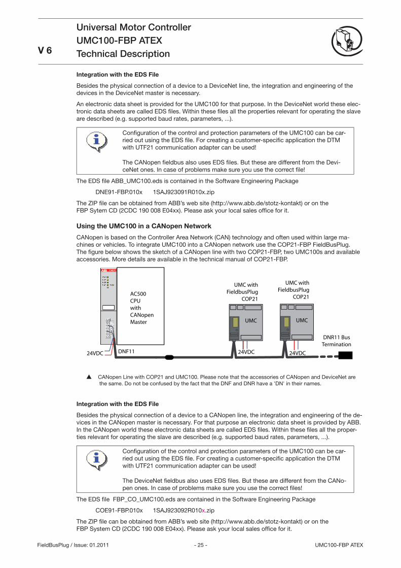
CANopen is based on the Controller Area Network (CAN) technology and often used within large ma-chines or vehicles. To integrate UMC100 into a CANopen network use the COP21-FBP FieldBusPlug. The fi gure below shows the sketch of a CANopen line with two COP21-FBP, two UMC100s and available accessories. More details are available in the technical manual of COP21-FBP.
UMC
24VDC
UMC
24VDC
UMC withFieldbusPlug
COP21
24VDC DNF11
UMC withFieldbusPlug
COP21AC500CPUwithCANopenMaster
DNR11 Bus Termination
CANopen Line with COP21 and UMC100. Please note that the accessories of CANopen and DeviceNet are the same. Do not be confused by the fact that the DNF and DNR have a 'DN' in their names.
Integration with the EDS File
Besides the physical connection of a device to a CANopen line, the integration and engineering of the de-vices in the CANopen master is necessary. For that purpose an electronic data sheet is provided by ABB. In the CANopen world these electronic data sheets are called EDS fi les. Within these fi les all the proper-ties relevant for operating the slave are described (e.g. supported baud rates, parameters, ...).
Confi guration of the control and protection parameters of the UMC100 can be car-ried out using the EDS fi le. For creating a customer-specifi c application the DTM with UTF21 communication adapter can be used!
The DeviceNet fi eldbus also uses EDS fi les. But these are different from the CANo-pen ones. In case of problems make sure you use the correct fi les!
The EDS fi le FBP_CO_UMC100.eds are contained in the Software Engineering Package
COE91-FBP.010x 1SAJ92092R010x.zip
The ZIP fi le can be obtained from ABB’s web site (http://www.abb.de/stotz-kontakt) or on the FBP System CD (2CDC 190 008 E04xx). Please ask your local sales offi ce for it.
- 26 -UMC100-FBP ATEX
Universal Motor ControllerUMC100-FBP ATEXTechnical Description V 6
FieldBusPlug / Issue: 01.2011
Using the UMC100 in a MODBUS RTU Network
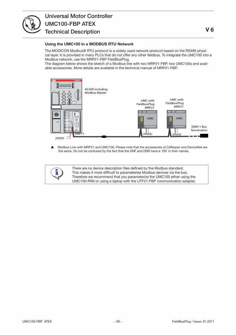
The MODICON Modbus® RTU protocol is a widely used network protocol based on the RS485 physi-cal layer. It is provided in many PLCs that do not offer any other fi eldbus. To integrate the UMC100 into a Modbus network, use the MRP21-FBP FieldBusPlug. The diagram below shows the sketch of a Modbus line with two MRP21-FBP, two UMC100s and avail-able accessories. More details are available in the technical manual of MRP21-FBP.
UMC
24VDC
UMC
24VDC
UMC withFieldbusPlug
MRP21
24VDC
DNF11
UMC withFieldbusPlug
MRP21
DNR11 Bus Termination
AC500 includingModbus Master
Modbus Line with MRP21 and UMC100. Please note that the accessories of CANopen and DeviceNet are the same. Do not be confused by the fact that the DNF and DNR have a 'DN' in their names.
There are no device description fi les defi ned by the Modbus standard. This makes it more diffi cult to parameterise Modbus devices via the bus. Therefore we recommend that you parameterize the UMC100 either using the UMC100-PAN or using a laptop with the UTF21-FBP communication adapter.
- 27 - UMC100-FBP ATEX
Universal Motor ControllerUMC100-FBP ATEXTechnical DescriptionV 6
FieldBusPlug / Issue: 01.2011
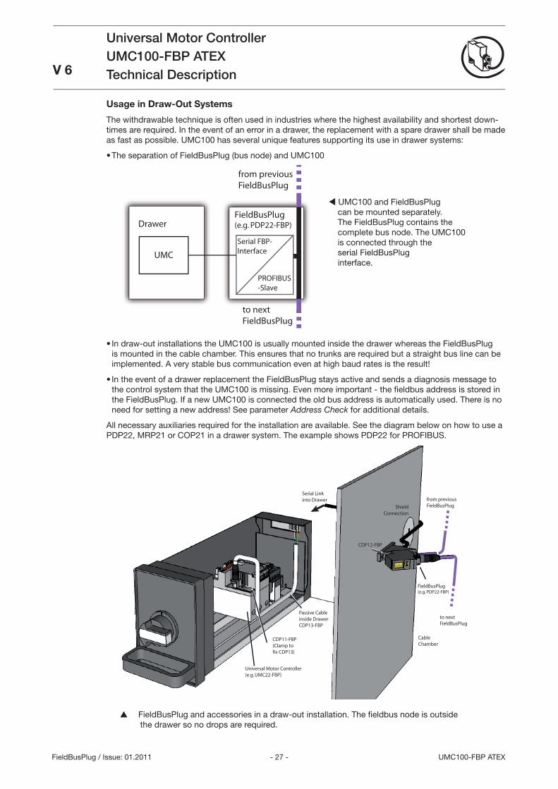
Usage in Draw-Out Systems
The withdrawable technique is often used in industries where the highest availability and shortest down-times are required. In the event of an error in a drawer, the replacement with a spare drawer shall be made as fast as possible. UMC100 has several unique features supporting its use in drawer systems:
The separation of FieldBusPlug (bus node) and UMC100
PROFIBUS-Slave
Serial FBP-InterfaceUMC
FieldBusPlug(e.g. PDP22-FBP)
to nextFieldBusPlug
from previousFieldBusPlug
Drawer
In draw-out installations the UMC100 is usually mounted inside the drawer whereas the FieldBusPlug is mounted in the cable chamber. This ensures that no trunks are required but a straight bus line can be implemented. A very stable bus communication even at high baud rates is the result!
In the event of a drawer replacement the FieldBusPlug stays active and sends a diagnosis message to the control system that the UMC100 is missing. Even more important - the fi eldbus address is stored in the FieldBusPlug. If a new UMC100 is connected the old bus address is automatically used. There is no need for setting a new address! See parameter Address Check for additional details.
All necessary auxiliaries required for the installation are available. See the diagram below on how to use a PDP22, MRP21 or COP21 in a drawer system. The example shows PDP22 for PROFIBUS.
ShieldConnection
Serial Linkinto Drawer
Passive Cableinside DrawerCDP13-FBP
CDP11-FBP(Clamp tofix CDP13)
Universal Motor Controller(e.g. UMC22-FBP)
FieldBusPlug(e.g. PDP22-FBP)
CDP12-FBP
from previousFieldBusPlug
to nextFieldBusPlug
CableChamber
FieldBusPlug and accessories in a draw-out installation. The fi eldbus node is outside the drawer so no drops are required.
•
•
•
UMC100 and FieldBusPlug can be mounted separately.The FieldBusPlug contains thecomplete bus node. The UMC100is connected through theserial FieldBusPluginterface.
- 28 -UMC100-FBP ATEX
Universal Motor ControllerUMC100-FBP ATEXTechnical Description
V 6
FieldBusPlug / Issue: 01.2011
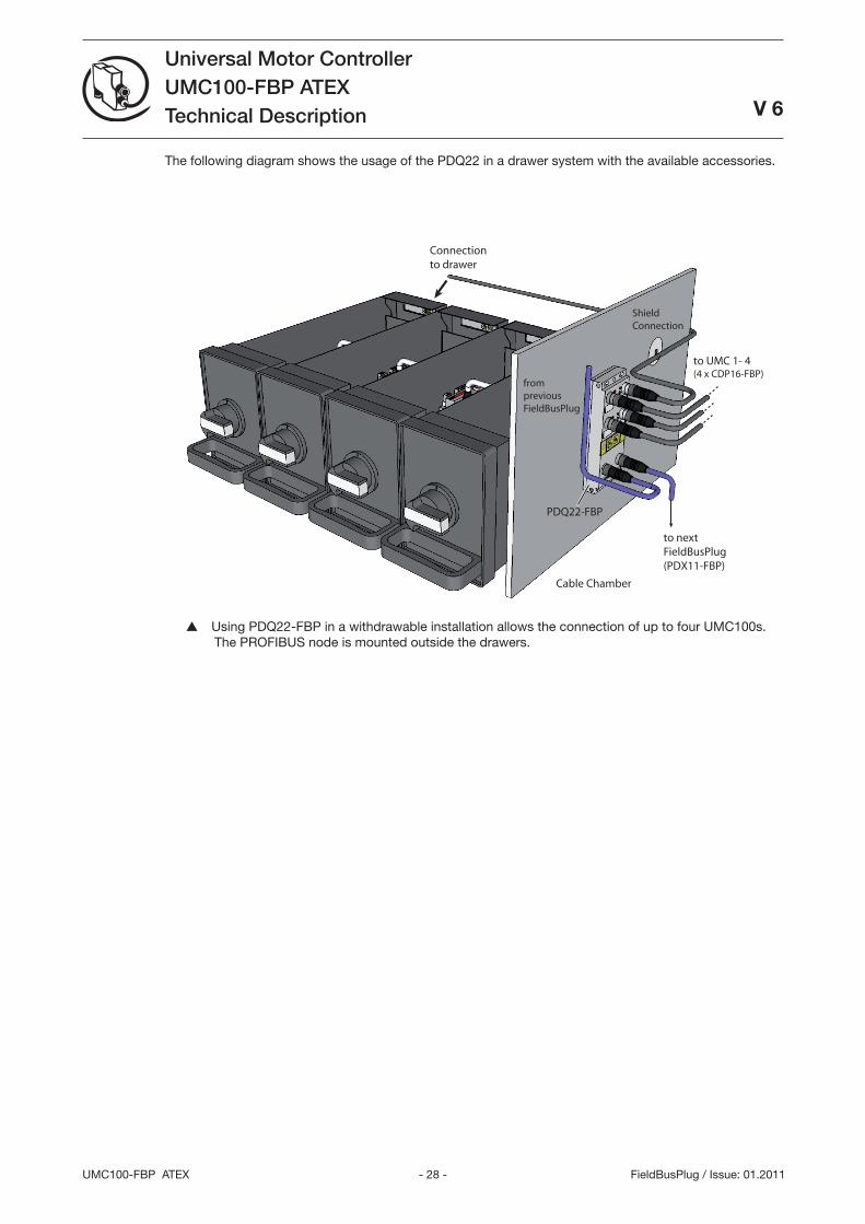
The following diagram shows the usage of the PDQ22 in a drawer system with the available accessories.
to nextFieldBusPlug(PDX11-FBP)
from previousFieldBusPlug
PDQ22-FBP
Cable Chamber
to UMC 1- 4(4 x CDP16-FBP)
ShieldConnection
Connectionto drawer
Using PDQ22-FBP in a withdrawable installation allows the connection of up to four UMC100s. The PROFIBUS node is mounted outside the drawers.
- 29 - UMC100-FBP ATEX
Universal Motor ControllerUMC100-FBP ATEXTechnical Description
V 6
FieldBusPlug / Issue: 01.2011
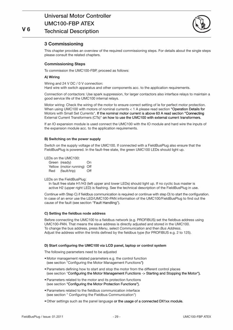
3 CommissioningThis chapter provides an overview of the required commissioning steps. For details about the single steps please consult the related chapters.
Commissioning Steps
To commission the UMC100-FBP, proceed as follows:
A) Wiring
Wiring and 24 V DC / 0 V connection: Hard wire with switch apparatus and other components acc. to the application requirements.
Connection of contactors: Use spark suppression, for larger contactors also interface relays to maintain a good service life of the UMC100 internal relays.
Motor wiring: Check the wiring of the motor to ensure correct setting of Ie for perfect motor protection. When using UMC100 with motors of nominal currents < 1 A please read section Operation Details forOperation Details for Motors with Small Set Currents. If the nominal motor current is above 6 A read section Connecting. If the nominal motor current is above 6 A read section ConnectingConnecting External Current Transformers (CTs) on how to use the UMC100 with external current transformers. on how to use the UMC100 with external current transformers.
If an IO expansion module is used connect the UMC100 with the IO module and hard wire the inputs of the expansion module acc. to the application requirements.
B) Switching on the power supply
Switch on the supply voltage of the UMC100. If connected with a FieldBusPlug also ensure that the FieldBusPlug is powered. In the fault-free state, the green UMC100 LEDs should light up. LEDs on the UMC100: Green (ready) On Yellow (motor running) Off Red (fault/trip) Off LEDs on the FieldBusPlug: In fault free state H1/H (left upper and lower LEDs) should light up. If no cyclic bus master is active H2 (upper right LED) is flashing. See the technical description of the FieldBusPlug in use.
Continue with Step C) if fieldbus communication is required or continue with step D) to start the configuration. In case of an error use the LED/UMC100-PAN information of the UMC100/FieldBusPlug to find out the cause of the fault (see section Fault Handling).
C) Setting the fieldbus node address
Before connecting the UMC100 to a fieldbus network (e.g. PROFIBUS) set the fieldbus address using UMC100-PAN. That means the slave address is directly adjusted and stored in the UMC100. To change the bus address, press Menu, select Communication and then Bus Address. Adjust the address within the limits defined by the fieldbus type (for PROFIBUS e.g. 2 to 125).
D) Start configuring the UMC100 via LCD panel, laptop or control system
The following parameters need to be adjusted
Motor management related parameters e.g. the control function (see section Configuring the Motor Management Functions)))
Parameters defining how to start and stop the motor from the different control places (see section Configuring the Motor Management Functions -> Starting and Stopping the Motor).Configuring the Motor Management Functions -> Starting and Stopping the Motor).).
Parameters related to the motor and its protection functions (see section Configuring the Motor Protection Functions).Configuring the Motor Protection Functions).).
Parameters related to the fieldbus communication interface (see section Configuring the Fieldbus Communication)
Other settings such as the panel language or the usage of a connected DX1xx module.or the usage of a connected DX1xx module.
•
•
•
•
•
- 0 -UMC100-FBP ATEX
Universal Motor ControllerUMC100-FBP ATEXTechnical Description
V 6
FieldBusPlug / Issue: 01.2011
Select the Required Configuration Mode for the UMC100-FBP
The UMC100 can be configured in different ways depending on your system setup:
Configuration via LCD panel
The device address has to be configured via LCD panel. And it is possible to adjust the other protec-tion and control parameters of the UMC100 using the panel. The configuration via LCD panel is good for stand-alone applications (without bus) and when no Laptop for parameterisation is in use. The configuration via LCD panel can be password-protected to prevent unintentional parameter changes.
Configuration from within the control system
Device description files allow the integration and configuration of a device in the fieldbus master. For PROFIBUS this file is called a GSD file. In case of CANopen and DeviceNet so-called EDS files are com-monly used. The UMC100 can be configured using these configuration files. A considerable benefit of this method of configuration is that the configuration is stored centrally in the control system and can be downloaded again in the event of a replacement.
If the UMC100 is connected via PROFIBUS and the control system supports the FDT/DTM technology it is also possible to configure the UMC100 using the PBDTM (PROFIBUS Device Type Manager) from within the system. The PBDTM offers a very user-friendly configuration interface which also allows to adapt the internal UMC100 application logic using the custom application editor. In online mode the PBDTM additionally provides access to all diagnosis, service and process data.
Configuration via Laptop
The configuration via laptop option is a convenient way to parameterise and monitor the UMC100. The FDT/DTM based configuration tool provides full access to all data available in the UMC100. The following functions are available:
Online and offline configuration and parameterisation of the UMC100
Monitoring and diagnosis of the UMC100 during operation
Function block based programming of a user specific application
Utilising of user roles and optional password protection for different tasks (e.g. engineering or operation)
The UTF21 communication adapter provides a point-to-point connection between a single UMC100 and your laptop. The top half of the following diagram shows this setup.
If several UMC100s are connected via PROFIBUS the UTP22 communication adapter can be used. This adapter connects your laptop to the PROFIBUS line and allows central configuration and monitoring of all UMC100s connected to this line. This is recommended for larger PROFIBUS installations.
For configuration via laptop use the ABB tool Asset Vision Basic. It is jointly used by ABB Instrumentation and ABB Control Products. It is based on the FDT/DTM standard.
The installation and use of the PBDTM is described in the PBDTM manual. It also provides general infor-mation about the FDT/DTM technology. Please read this manual carefully if you are unfamiliar with the FDM/DTM technology.
•
•
•
•
- 1 - UMC100-FBP ATEX
Universal Motor ControllerUMC100-FBP ATEXTechnical DescriptionV 6
FieldBusPlug / Issue: 01.2011
UMCUTF21
24 V DC
USBInterface
UMCFieldBusPlug
Interface
UMC
24 V DC
UMC
24 V DC
UMCwithFieldBusPlug
PDP22
PDA12
UTP22
USBInterface
24 V DC
Connection of the Service -Laptop & PROFIBUS adapteronly when required also inparallel to the PLC/DCS
PROFIBUS Master
PDA11
PROFIBUS CableDSUB9 / DSUB9
Service Laptop
Service Laptop
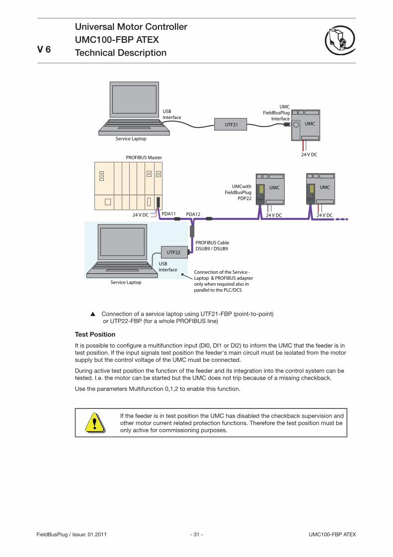
Connection of a service laptop using UTF21-FBP (point-to-point) or UTP22-FBP (for a whole PROFIBUS line)
Test Position
It is possible to confi gure a multifunction input (DI0, DI1 or DI2) to inform the UMC that the feeder is in test position. If the input signals test position the feeder's main circuit must be isolated from the motor supply but the control voltage of the UMC must be connected.
During active test position the function of the feeder and its integration into the control system can be tested. I.e. the motor can be started but the UMC does not trip because of a missing checkback.
Use the parameters Multifunction 0,1,2 to enable this function.
If the feeder is in test position the UMC has disabled the checkback supervision and other motor current related protection functions. Therefore the test position must be only active for commissioning purposes.

- 2 -UMC100-FBP ATEX
Universal Motor ControllerUMC100-FBP ATEXTechnical Description
V 6
FieldBusPlug / Issue: 01.2011
- - UMC100-FBP ATEX
Universal Motor ControllerUMC100-FBP ATEXTechnical DescriptionV 6
FieldBusPlug / Issue: 01.2011
4 Confi guring the Motor Protection FunctionsIn this chapter you fi nd information on how to confi gure the different UMC protection functions. The following topics are covered:
Function and parameters of the electronic overload protection, the thermal memory and points to consider if the motor is started cyclically (e.g. S motor operation mode)
Locked rotor protection during motor start
Overcurrent and undercurrent protection during normal operation
Imbalance protection
Phase loss protection
Thermistor motor protection
Earth fault protection with auxiliary device CEM11-FBP
Protection functions can be either on or off. If switched on, they can trigger a protection trip or a warning only (excluding the thermal overload which is always active and triggers a trip). For some functions an op-tional delay can be specifi ed. Some protection functions are only active after motor start-up while others are active during motor start.
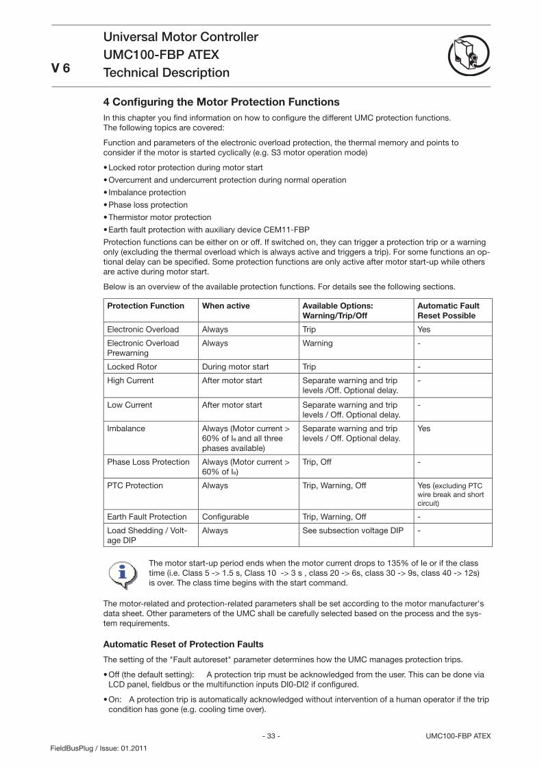
Below is an overview of the available protection functions. For details see the following sections.
Protection Function When active Available Options: Warning/Trip/Off
Automatic Fault Reset Possible
Electronic Overload Always Trip Yes
Electronic Overload Prewarning
Always Warning -
Locked Rotor During motor start Trip -
High Current After motor start Separate warning and trip levels /Off. Optional delay.
-
Low Current After motor start Separate warning and trip levels / Off. Optional delay.
-
Imbalance Always (Motor current > 60% of Ie and all three phases available)
Separate warning and trip levels / Off. Optional delay.
Yes
Phase Loss Protection Always (Motor current > 60% of Ie)
Trip, Off -
PTC Protection Always Trip, Warning, Off Yes (excluding PTC wire break and short circuit)
Earth Fault Protection Confi gurable Trip, Warning, Off -
Load Shedding / Volt-age DIP
Always See subsection voltage DIP -
The motor start-up period ends when the motor current drops to 15% of Ie or if the class time (i.e. Class 5 -> 1.5 s, Class 10 -> s , class 20 -> 6s, class 0 -> 9s, class 40 -> 12s) is over. The class time begins with the start command.
The motor-related and protection-related parameters shall be set according to the motor manufacturer's data sheet. Other parameters of the UMC shall be carefully selected based on the process and the sys-tem requirements.
Automatic Reset of Protection Faults
The setting of the Fault autoreset parameter determines how the UMC manages protection trips.
Off (the default setting): A protection trip must be acknowledged from the user. This can be done via LCD panel, fi eldbus or the multifunction inputs DI0-DI2 if confi gured.
On: A protection trip is automatically acknowledged without intervention of a human operator if the trip condition has gone (e.g. cooling time over).
•
•
•
•
•
•
•
•
- 4 -UMC100-FBP ATEX
Universal Motor ControllerUMC100-FBP ATEXTechnical Description
V 6
FieldBusPlug / Issue: 01.2011
Electronic Overload Protection
The UMC protects three-phase AC motors in compliance with IEC 60947-4-1. The tripping class can be set to class 5, 10, 20, 0 or 40. The advanced thermal motor model considers both the copper and iron parts of the motor thus providing the best protection of the motor.
Before an electronic overload trip actually happens, a pre-warning can be generated. During high over-load situations the prewarning might be raised just a few seconds before the actual trip happens.
The presently used thermal capacity (0...100%) of the motor is available to the user and thus a prediction of the time to trip for the current load situation. If the motor is switched off the time to trip shows 655 sec (never trips). If the motor is running the predicted trip time is updated regularly. The smaller the value the earlier the trip happens.
After an overload trip, the remaining cooling down time (=time to restart) is calculated regularly and also available to the user. The motor can be restarted if the cooling time is 0 sec.
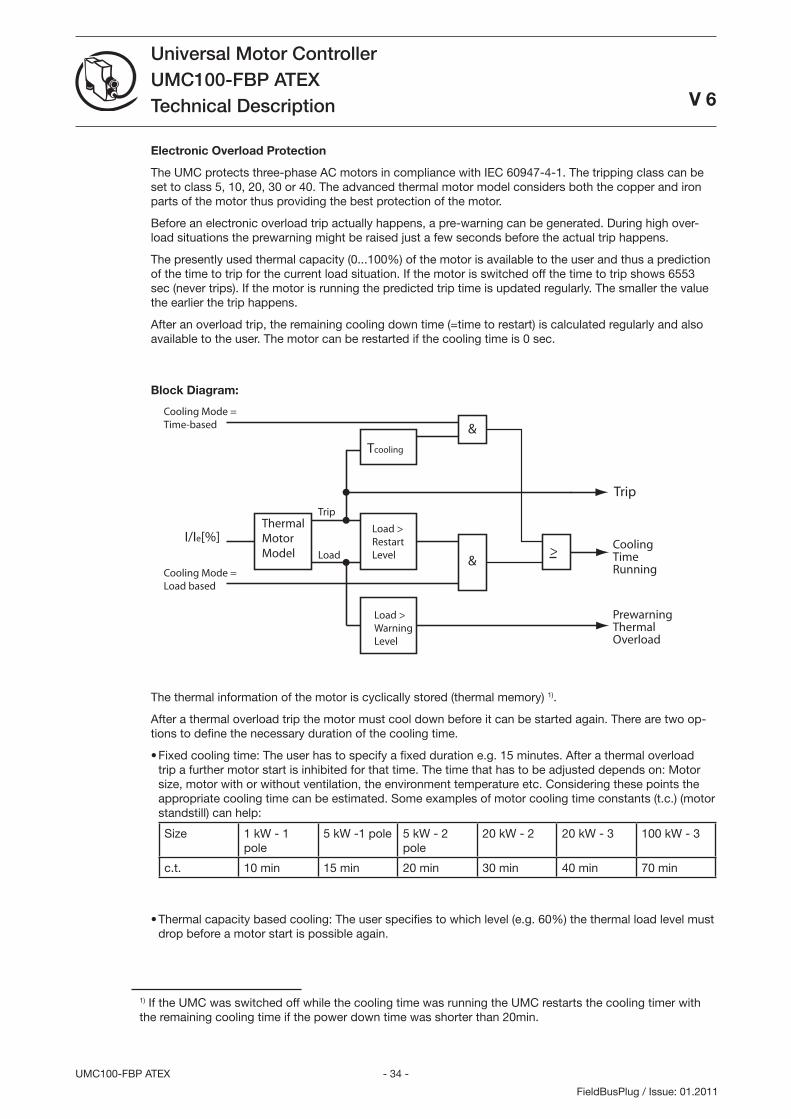
Block Diagram:
I/Ie[%]ThermalMotorModel
CoolingTimeRunning
Load >RestartLevel
Trip
&Cooling Mode =Load based
>
Tcooling
&Cooling Mode =Time-based
Load
Trip
Load >WarningLevel
PrewarningThermalOverload
The thermal information of the motor is cyclically stored (thermal memory) 1).
After a thermal overload trip the motor must cool down before it can be started again. There are two op-tions to define the necessary duration of the cooling time.
Fixed cooling time: The user has to specify a fixed duration e.g. 15 minutes. After a thermal overload trip a further motor start is inhibited for that time. The time that has to be adjusted depends on: Motor size, motor with or without ventilation, the environment temperature etc. Considering these points the appropriate cooling time can be estimated. Some examples of motor cooling time constants (t.c.) (motor standstill) can help:
Size 1 kW - 1 pole
5 kW -1 pole 5 kW - 2 pole
20 kW - 2 20 kW - 100 kW -
c.t. 10 min 15 min 20 min 0 min 40 min 70 min
Thermal capacity based cooling: The user specifies to which level (e.g. 60%) the thermal load level must drop before a motor start is possible again.
•
•
1) If the UMC was switched off while the cooling time was running the UMC restarts the cooling timer with the remaining cooling time if the power down time was shorter than 20min.
- 5 - UMC100-FBP ATEX
Universal Motor ControllerUMC100-FBP ATEXTechnical Description
V 6
FieldBusPlug / Issue: 01.2011
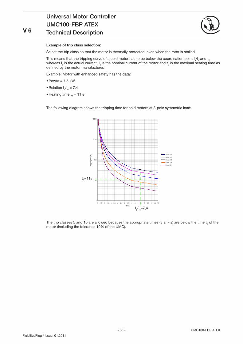
Example of trip class selection:
Select the trip class so that the motor is thermally protected, even when the rotor is stalled.
This means that the tripping curve of a cold motor has to be below the coordination point Ia/Ie and tE whereas Ia is the actual current, Ie is the nominal current of the motor and tE is the maximal heating time as defined by the motor manufacturer.
Example: Motor with enhanced safety has the data:
Power = 7.5 kW
Relation Ia/Ie = 7.4
Heating time tE = 11 s
The following diagram shows the tripping time for cold motors at -pole symmetric load:
The trip classes 5 and 10 are allowed because the appropriate times ( s, 7 s) are below the time tE of the motor (including the tolerance 10% of the UMC).
•
•
•
1
10
100
1000
10000
1 1,5 2 2,5 3 3,5 4 4,5 5 5,5 6 6,5 7 7,5 8 8,5 9 9,5 10
I / Ie
trip
ping
tim
e [s
] Clas s 40EClas s 30EClas s 20EClas s 10EClas s 5E
Ia/Ie=7,4
tE=11s
- 6 -UMC100-FBP ATEX
Universal Motor ControllerUMC100-FBP ATEXTechnical Description V 6
FieldBusPlug / Issue: 01.2011
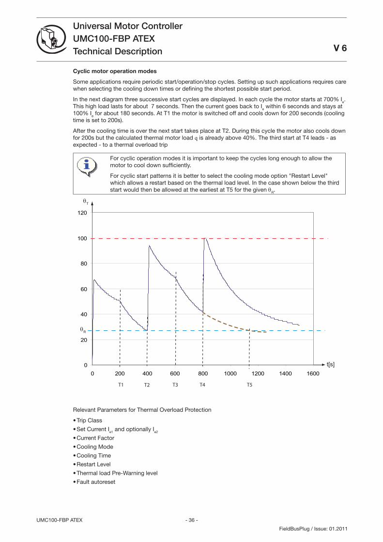
Cyclic motor operation modes
Some applications require periodic start/operation/stop cycles. Setting up such applications requires care when selecting the cooling down times or defi ning the shortest possible start period.
In the next diagram three successive start cycles are displayed. In each cycle the motor starts at 700% Ie. This high load lasts for about 7 seconds. Then the current goes back to Ie within 6 seconds and stays at 100% Ie for about 180 seconds. At T1 the motor is switched off and cools down for 200 seconds (cooling time is set to 200s).
After the cooling time is over the next start takes place at T2. During this cycle the motor also cools down for 200s but the calculated thermal motor load q is already above 40%. The third start at T4 leads - as expected - to a thermal overload trip
For cyclic operation modes it is important to keep the cycles long enough to allow the motor to cool down suffi ciently.
For cyclic start patterns it is better to select the cooling mode option Restart Level which allows a restart based on the thermal load level. In the case shown below the third start would then be allowed at the earliest at T5 for the given θR.
θT
t[s]
T1 T2 T4
0
20
40
60
80
100
120
0 200 400 600 800 1000 1200 1400 1600
T3
θR
T5
Relevant Parameters for Thermal Overload Protection
Trip Class
Set Current Ie1 and optionally Ie2
Current Factor
Cooling Mode
Cooling Time
Restart Level
Thermal load Pre-Warning level
Fault autoreset
•
•
•
•
•
•
•
•
- 7 - UMC100-FBP ATEX
Universal Motor ControllerUMC100-FBP ATEXTechnical DescriptionV 6
FieldBusPlug / Issue: 01.2011
Long Start, Locked Rotor Protection
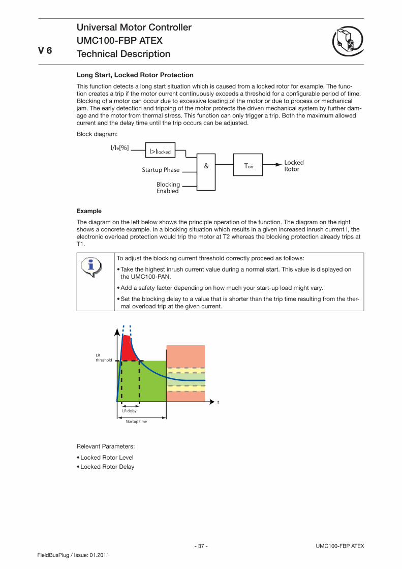
This function detects a long start situation which is caused from a locked rotor for example. The func-tion creates a trip if the motor current continuously exceeds a threshold for a confi gurable period of time. Blocking of a motor can occur due to excessive loading of the motor or due to process or mechanical jam. The early detection and tripping of the motor protects the driven mechanical system by further dam-age and the motor from thermal stress. This function can only trigger a trip. Both the maximum allowed current and the delay time until the trip occurs can be adjusted.
Block diagram:
&
I/Ie[%] I>Ilocked
Startup PhaseTon
LockedRotor
BlockingEnabled
Example
The diagram on the left below shows the principle operation of the function. The diagram on the right shows a concrete example. In a blocking situation which results in a given increased inrush current I, the electronic overload protection would trip the motor at T2 whereas the blocking protection already trips at T1.
To adjust the blocking current threshold correctly proceed as follows:
Take the highest inrush current value during a normal start. This value is displayed on the UMC100-PAN.
Add a safety factor depending on how much your start-up load might vary.
Set the blocking delay to a value that is shorter than the trip time resulting from the ther-mal overload trip at the given current.
•
•
•
t
LR delay
LR threshold
Startup time
Relevant Parameters:
Locked Rotor Level
Locked Rotor Delay
•
•
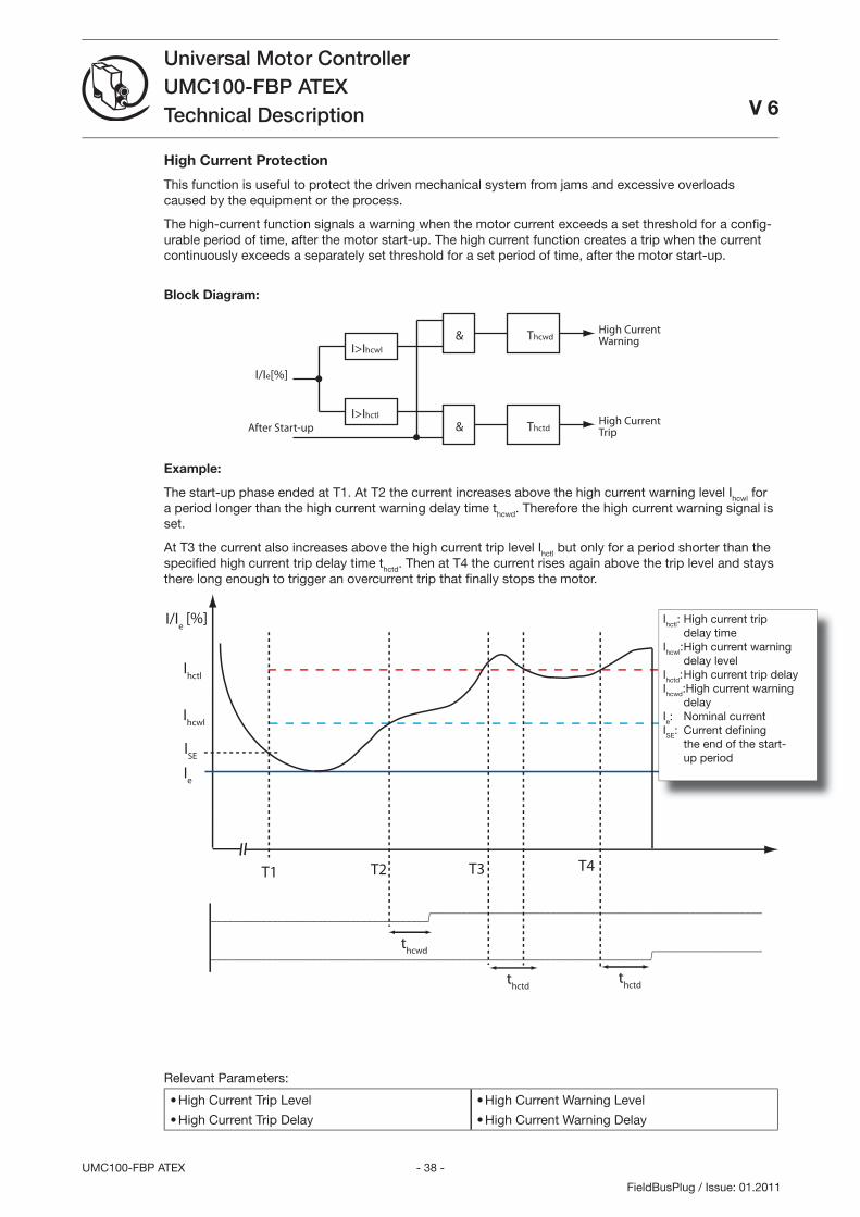
- 8 -UMC100-FBP ATEX
Universal Motor ControllerUMC100-FBP ATEXTechnical Description V 6
FieldBusPlug / Issue: 01.2011
High Current Protection
This function is useful to protect the driven mechanical system from jams and excessive overloads caused by the equipment or the process.
The high-current function signals a warning when the motor current exceeds a set threshold for a confi g-urable period of time, after the motor start-up. The high current function creates a trip when the current continuously exceeds a separately set threshold for a set period of time, after the motor start-up.
Block Diagram:
&
I/Ie[%]
I>Ihcwl
ThcwdHigh CurrentWarning
After Start-upI>Ihctl
& ThctdHigh CurrentTrip
Example:
The start-up phase ended at T1. At T2 the current increases above the high current warning level Ihcwl for a period longer than the high current warning delay time thcwd. Therefore the high current warning signal is set.
At T the current also increases above the high current trip level Ihctl but only for a period shorter than the specifi ed high current trip delay time thctd. Then at T4 the current rises again above the trip level and stays there long enough to trigger an overcurrent trip that fi nally stops the motor.
[%]
t
I/Ie
Ihctl
Ihcwl
Ie
T1
ISE
---------------------------------------/===========================================================
-------------------------------------------------------------------------------/===================
T2 T3
thcwd
thctd
thctd
T4
Relevant Parameters:
High Current Trip Level
High Current Trip Delay
•
•
High Current Warning Level
High Current Warning Delay
•
•
Ihctl: High current trip delay timeIhcwl: High current warning delay levelIhctd: High current trip delayIhcwd:High current warning delayIe: Nominal currentISE: Current defi ning the end of the start- up period
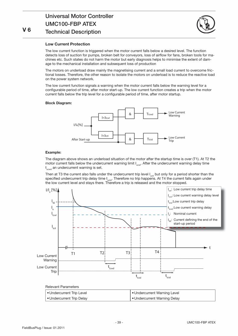
- 9 - UMC100-FBP ATEX
Universal Motor ControllerUMC100-FBP ATEXTechnical DescriptionV 6
FieldBusPlug / Issue: 01.2011
Low Current Warning
Low Current Trip
Low Current Protection
The low current function is triggered when the motor current falls below a desired level. The function detects loss of suction for pumps, broken belt for conveyors, loss of airfl ow for fans, broken tools for ma-chines etc. Such states do not harm the motor but early diagnosis helps to minimise the extent of dam-age to the mechanical installation and subsequent loss of production
The motors on underload draw mainly the magnetising current and a small load current to overcome fric-tional losses. Therefore, the other reason to isolate the motors on underload is to reduce the reactive load on the power system network.
The low current function signals a warning when the motor current falls below the warning level for a confi gurable period of time, after motor start-up. The low current function creates a trip when the motor current falls below the trip level for a confi gurable period of time, after motor startup.
Block Diagram:
&
I/Ie[%]
I<Ilcwl
TlcwdLow CurrentWarning
After Start-upI<Ilctl
& TlctdLow CurrentTrip
Example:
The diagram above shows an underload situation of the motor after the startup time is over (T1). At T2 the motor current falls below the undercurrent warning limit Iucwl. After the undercurrent warning delay time tucwd an undercurrent warning is set.
Then at T the current also falls under the undercurrent trip level Iuctl but only for a period shorter than the specifi ed undercurrent trip delay time tuctd. Therefore no trip happens. At T4 the current falls again under the low current level and stays there. Therefore a trip is released and the motor stopped.
[%]
t
I/Ie
Ilctl
Ilcwl
Ie
T1
ISE
---------------------------------------/===========================================================
-------------------------------------------------------------------------------/===================
T2 T3
tlcwd
tlctd
tlctd
T4
Relevant Parameters
Undercurrent Trip Level
Undercurrent Trip Delay
•
•
Undercurrent Warning Level
Undercurrent Warning Delay
•
•
Ilctl: Low current trip delay time
Ilcwl: Low current warning delay level
tlctd:Low current trip delay
tlcwd:Low current warning delay
Ie: Nominal current
ISE: Current defi ning the end of the start-up period
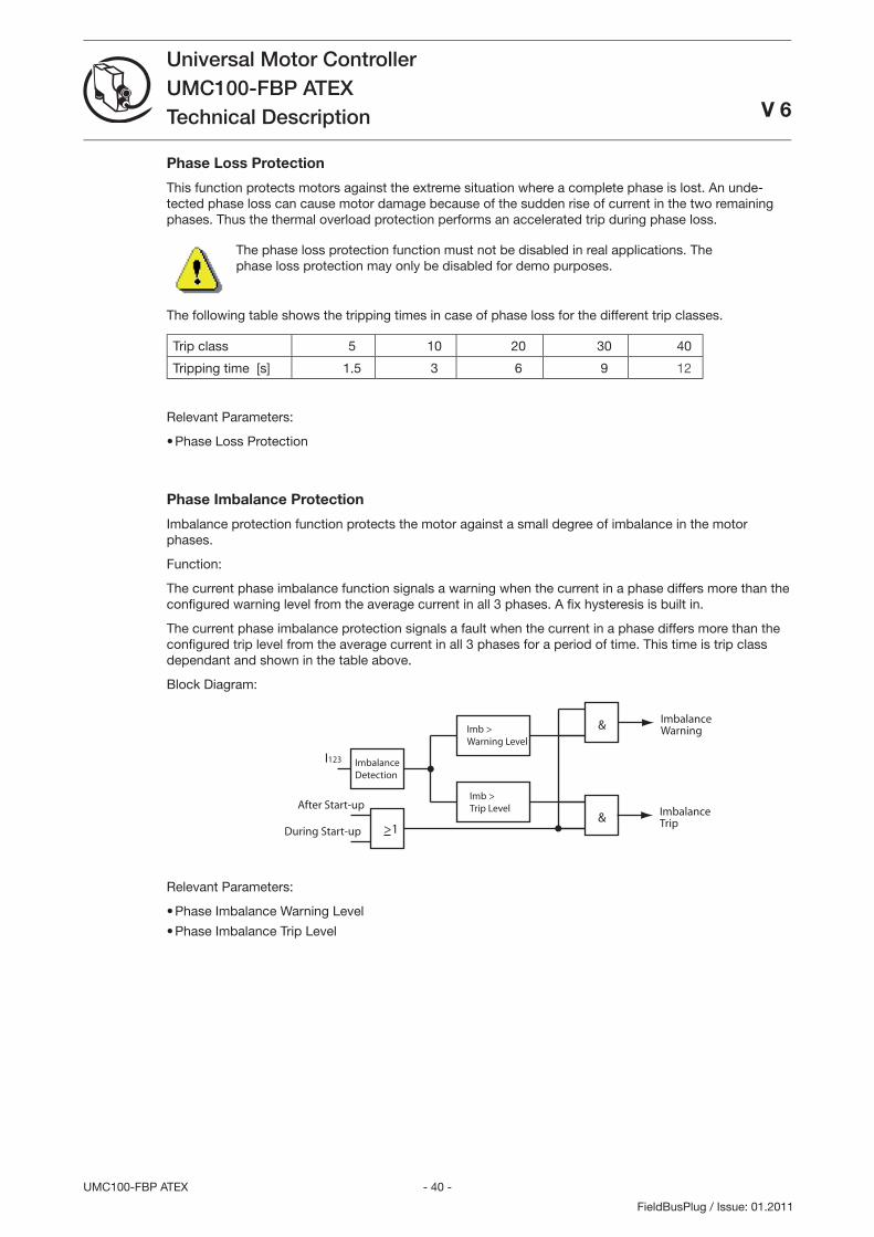
- 40 -UMC100-FBP ATEX
Universal Motor ControllerUMC100-FBP ATEXTechnical Description V 6
FieldBusPlug / Issue: 01.2011
Phase Loss Protection
This function protects motors against the extreme situation where a complete phase is lost. An unde-tected phase loss can cause motor damage because of the sudden rise of current in the two remaining phases. Thus the thermal overload protection performs an accelerated trip during phase loss.
The phase loss protection function must not be disabled in real applications. The phase loss protection may only be disabled for demo purposes.
The following table shows the tripping times in case of phase loss for the different trip classes.
Trip class 5 10 20 0 40
Tripping time [s] 1.5 6 9 12
Relevant Parameters:
Phase Loss Protection
Phase Imbalance Protection
Imbalance protection function protects the motor against a small degree of imbalance in the motor phases.
Function:
The current phase imbalance function signals a warning when the current in a phase differs more than the confi gured warning level from the average current in all phases. A fi x hysteresis is built in.
The current phase imbalance protection signals a fault when the current in a phase differs more than the confi gured trip level from the average current in all phases for a period of time. This time is trip class dependant and shown in the table above.
Block Diagram:
I123
Imb >Warning Level
ImbalanceWarning
After Start-up& Imbalance
Trip
ImbalanceDetection
Imb >Trip Level
During Start-up >1
&
Relevant Parameters:
Phase Imbalance Warning Level
Phase Imbalance Trip Level
•
•
•
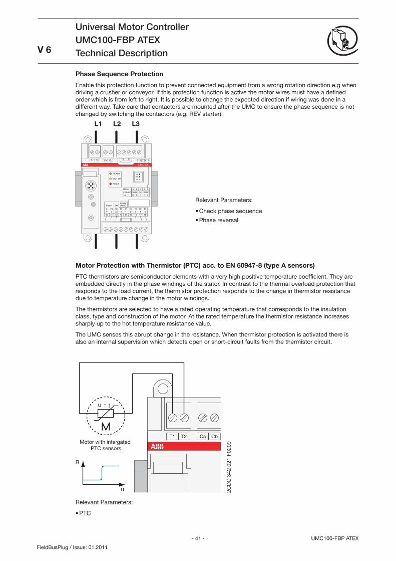
- 41 - UMC100-FBP ATEX
Universal Motor ControllerUMC100-FBP ATEXTechnical Description
V 6
FieldBusPlug / Issue: 01.2011
Phase Sequence Protection
Enable this protection function to prevent connected equipment from a wrong rotation direction e.g when driving a crusher or conveyor. If this protection function is active the motor wires must have a defined order which is from left to right. It is possible to change the expected direction if wiring was done in a different way. Take care that contactors are mounted after the UMC to ensure the phase sequence is not changed by switching the contactors (e.g. REV starter).
L1 L2 L3
181716151413121110
DIDIDIDIDIDI
24V
240543210OutVV
Power
T1
8
DO1
7
DO0
6
DOC
5
DOC
9
DO2
8765 9T2 Ca Cb
UMC100
READY
MOT.ON
FAULT
Relay
230VAC1A
Inputs24VDC
DC
Relevant Parameters:
Check phase sequence
Phase reversal
•
•
Motor Protection with Thermistor (PTC) acc. to EN 60947-8 (type A sensors)
PTC thermistors are semiconductor elements with a very high positive temperature coefficient. They are embedded directly in the phase windings of the stator. In contrast to the thermal overload protection that responds to the load current, the thermistor protection responds to the change in thermistor resistance due to temperature change in the motor windings.
The thermistors are selected to have a rated operating temperature that corresponds to the insulation class, type and construction of the motor. At the rated temperature the thermistor resistance increases sharply up to the hot temperature resistance value.
The UMC senses this abrupt change in the resistance. When thermistor protection is activated there is also an internal supervision which detects open or short-circuit faults from the thermistor circuit.
T1 T2 Ca Cb
u
R
u
Motor with intergated PTC sensors
2CD
C 3
42 0
21 F
0209
Relevant Parameters:
PTC•
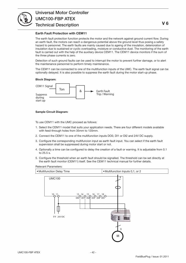
- 42 -UMC100-FBP ATEX
Universal Motor ControllerUMC100-FBP ATEXTechnical Description
V 6
FieldBusPlug / Issue: 01.2011
Earth Fault Protection with CEM11
The earth fault protection function protects the motor and the network against ground current flow. During an earth fault, the motors can reach a dangerous potential above the ground level thus posing a safety hazard to personnel. The earth faults are mainly caused due to ageing of the insulation, deterioration of insulation due to sustained or cyclic overloading, moisture or conductive dust. The monitoring of the earth fault is carried out with the help of the auxiliary device CEM11. The CEM11 device monitors if the sum of the three phase currents is zero.
Detection of such ground faults can be used to interrupt the motor to prevent further damage, or to alert the maintenance personnel to perform timely maintenance.
The CEM11 can be connected to one of the multifunction inputs of the UMC. The earth fault signal can be optionally delayed. It is also possible to suppress the earth fault during the motor start-up phase.
Block Diagram:
Earth FaultTrip / Warning
CEM11 SignalTon &
Suppressduring start up
Sample Circuit Diagram:
To use CEM11 with the UMC proceed as follows:
Select the CEM11 model that suits your application needs. There are four different models available with feed-through holes from 5mm to 120mm.
Connect the CEM11 to one of the multifunction inputs DO0, DI1 or DI2 and 24V DC supply.
Configure the corresponding multifuncion input as earth fault input. You can select if the earth fault supervision shall be suppressed during motor start or not.
Optionally a time can be configured to delay the creation of a fault or warning. It is adjustable from 0.1 to 25.5 s.
Configure the threshold when an earth fault should be signalled. The threshold can be set directly at the earth fault monitor (CEM11) itself. See the CEM11 technical manual for further details.
Relevant Parameters:
Multifunction Delay Time• Multifunction Inputs 0,1, or 2•
UMC100 3
24 V DC
10 11 13 14 15 16 17 18
DI0 DI1 DI2 DI3 DI4 DI5
0 V
M
3
1.
2.
.
4.
5.
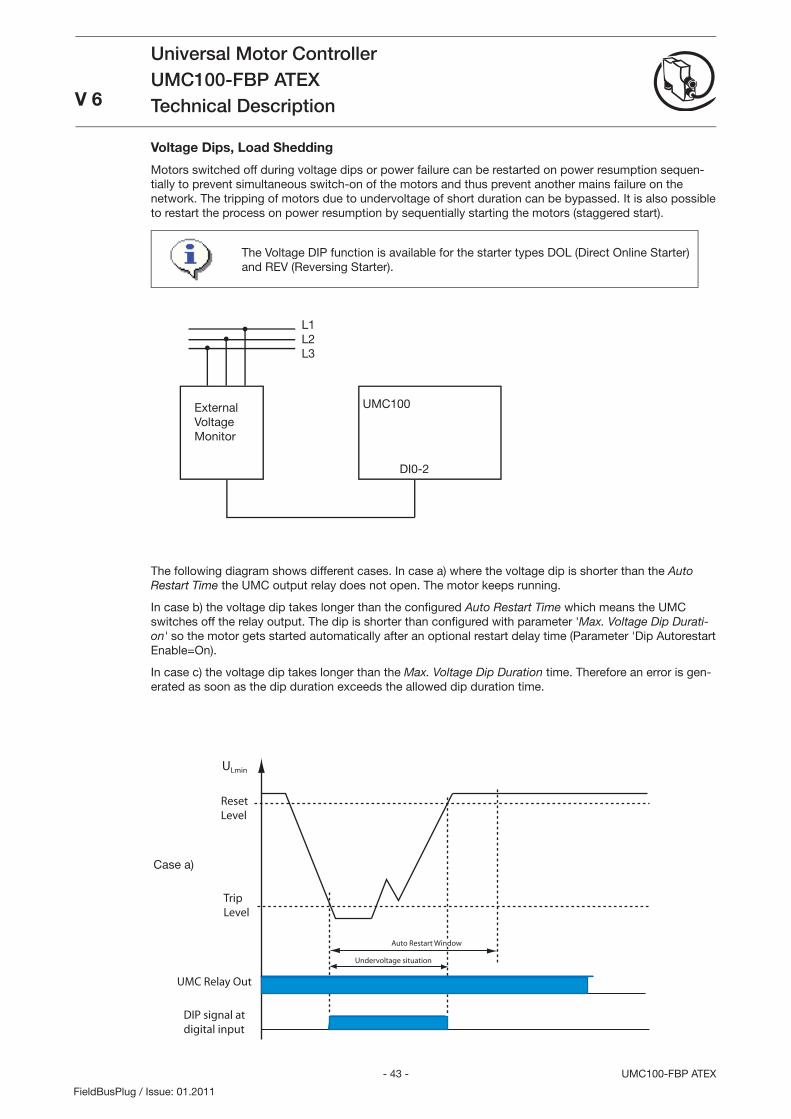
- 4 - UMC100-FBP ATEX
Universal Motor ControllerUMC100-FBP ATEXTechnical DescriptionV 6
FieldBusPlug / Issue: 01.2011
Voltage Dips, Load Shedding
Motors switched off during voltage dips or power failure can be restarted on power resumption sequen-tially to prevent simultaneous switch-on of the motors and thus prevent another mains failure on the network. The tripping of motors due to undervoltage of short duration can be bypassed. It is also possible to restart the process on power resumption by sequentially starting the motors (staggered start).
ULmin
Reset Level
TripLevel
UMC Relay Out
Undervoltage situation
Auto Restart Window
DIP signal atdigital input
ULmin
Reset Level
TripLevel
UMC Relay Out
Undervoltage situation
Auto Restart Window
DIP signal atdigital input
RestartDelay
Max. DIP Duration
ULmin
Reset Level
TripLevel
UMC Relay Out
Undervoltage situation
DIP signal atdigital input
Max. DIP Duration
UMC VoltageDIP Error
Case a)
The following diagram shows different cases. In case a) where the voltage dip is shorter than the Auto Restart Time the UMC output relay does not open. The motor keeps running.
In case b) the voltage dip takes longer than the confi gured Auto Restart Time which means the UMC switches off the relay output. The dip is shorter than confi gured with parameter 'Max. Voltage Dip Durati-on' so the motor gets started automatically after an optional restart delay time (Parameter 'Dip Autorestart Enable=On).
In case c) the voltage dip takes longer than the Max. Voltage Dip Duration time. Therefore an error is gen-erated as soon as the dip duration exceeds the allowed dip duration time.
External Voltage Monitor
UMC100
L1L2L
DI0-2
The Voltage DIP function is available for the starter types DOL (Direct Online Starter) and REV (Reversing Starter).
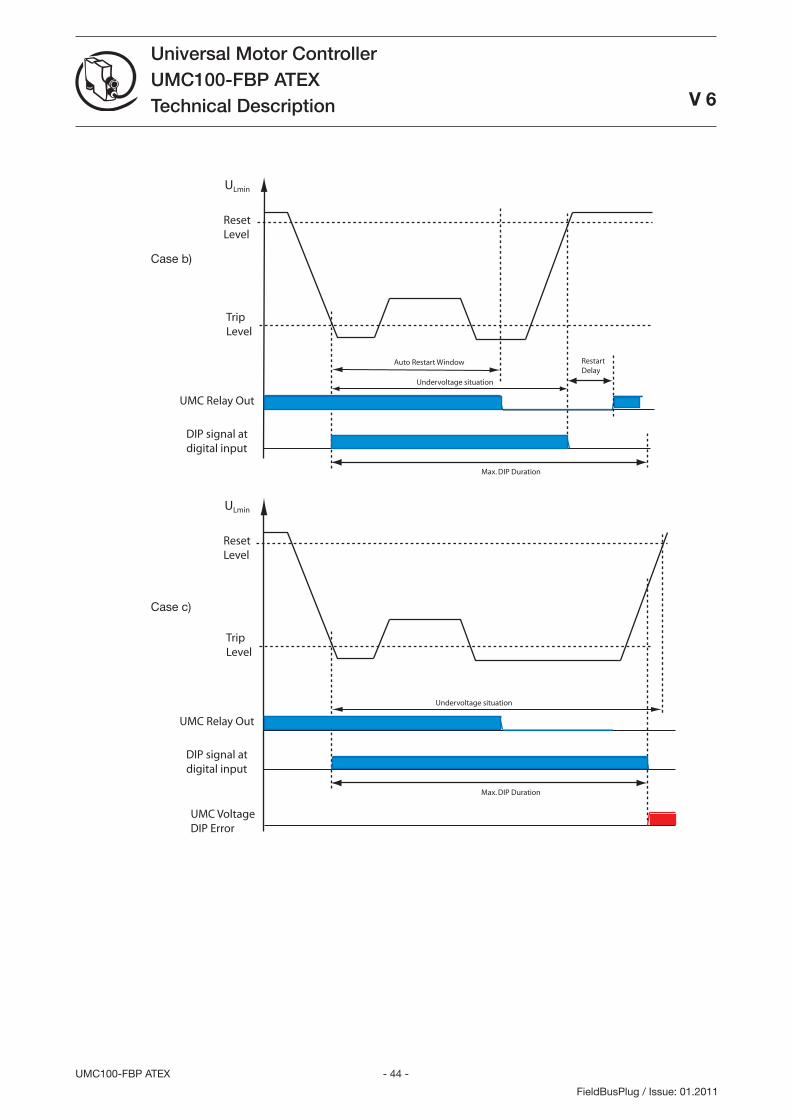
- 44 -UMC100-FBP ATEX
Universal Motor ControllerUMC100-FBP ATEXTechnical Description
V 6
FieldBusPlug / Issue: 01.2011
ULmin
Reset Level
TripLevel
UMC Relay Out
Undervoltage situation
Auto Restart Window
DIP signal atdigital input
ULmin
Reset Level
TripLevel
UMC Relay Out
Undervoltage situation
Auto Restart Window
DIP signal atdigital input
RestartDelay
Max. DIP Duration
ULmin
Reset Level
TripLevel
UMC Relay Out
Undervoltage situation
DIP signal atdigital input
Max. DIP Duration
UMC VoltageDIP Error
Case c)
Case b)
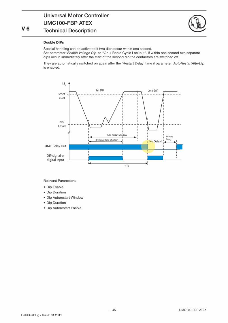
- 45 - UMC100-FBP ATEX
Universal Motor ControllerUMC100-FBP ATEXTechnical DescriptionV 6
FieldBusPlug / Issue: 01.2011
Relevant Parameters:
Dip Enable
Dip Duration
Dip Autorestart Window
Dip Duration
Dip Autorestart Enable
•
•
•
•
•
UL
Reset Level
TripLevel
UMC Relay Out
Undervoltage situation
Auto Restart Window
DIP signal atdigital input
RestartDelay
1st DIP 2nd DIP
<1s
No Delay!
Double DIPs
Special handling can be activated if two dips occur within one second. Set parameter 'Enable Voltage Dip' to “On + Rapid Cycle Lockout”. If within one second two separate dips occur, immediately after the start of the second dip the contactors are switched off.
They are automatically switched on again after the ‘Restart Delay’ time if parameter 'AutoRestartAfterDip' is enabled.

- 46 -UMC100-FBP ATEX
Universal Motor ControllerUMC100-FBP ATEXTechnical Description
V 6
FieldBusPlug / Issue: 01.2011
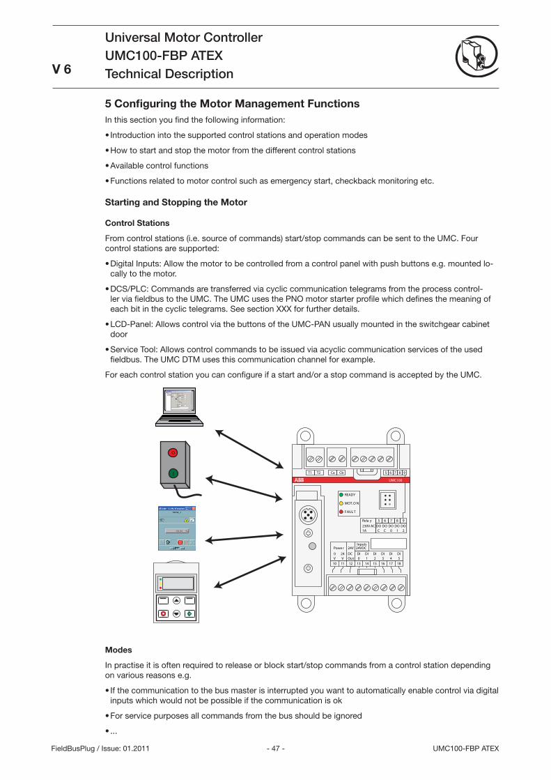
- 47 - UMC100-FBP ATEX
Universal Motor ControllerUMC100-FBP ATEXTechnical Description
V 6
FieldBusPlug / Issue: 01.2011
5 Configuring the Motor Management FunctionsIn this section you find the following information:
Introduction into the supported control stations and operation modes
How to start and stop the motor from the different control stations
Available control functions
Functions related to motor control such as emergency start, checkback monitoring etc.
Starting and Stopping the Motor
Control Stations
From control stations (i.e. source of commands) start/stop commands can be sent to the UMC. Four control stations are supported:
Digital Inputs: Allow the motor to be controlled from a control panel with push buttons e.g. mounted lo-cally to the motor.
DCS/PLC: Commands are transferred via cyclic communication telegrams from the process control-ler via fieldbus to the UMC. The UMC uses the PNO motor starter profile which defines the meaning of each bit in the cyclic telegrams. See section XXX for further details.
LCD-Panel: Allows control via the buttons of the UMC-PAN usually mounted in the switchgear cabinet door
Service Tool: Allows control commands to be issued via acyclic communication services of the used fieldbus. The UMC DTM uses this communication channel for example.
For each control station you can configure if a start and/or a stop command is accepted by the UMC.
o
I
181716151413121110
DIDIDIDIDIDI
24V
240543210OutVV
Powe r
T1
8DO
1
7DO
0
6DOC
5DOC
9DO
2
8765 9T2 Ca Cb
UMC100
READY
MOT .O N
FAUL T
Rela y230V AC1A
Inputs24VDC
DC
Modes
In practise it is often required to release or block start/stop commands from a control station depending on various reasons e.g.
If the communication to the bus master is interrupted you want to automatically enable control via digital inputs which would not be possible if the communication is ok
For service purposes all commands from the bus should be ignored
...
•
•
•
•
•
•
•
•
•
•
•
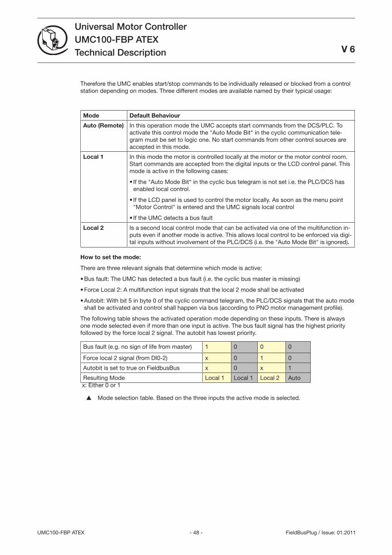
- 48 -UMC100-FBP ATEX
Universal Motor ControllerUMC100-FBP ATEXTechnical Description
V 6
FieldBusPlug / Issue: 01.2011
Therefore the UMC enables start/stop commands to be individually released or blocked from a control station depending on modes. Three different modes are available named by their typical usage:
Mode Default Behaviour
Auto (Remote) In this operation mode the UMC accepts start commands from the DCS/PLC. To activate this control mode the Auto Mode Bit in the cyclic communication tele-gram must be set to logic one. No start commands from other control sources are accepted in this mode.
Local 1 In this mode the motor is controlled locally at the motor or the motor control room. Start commands are accepted from the digital inputs or the LCD control panel. This mode is active in the following cases:
If the Auto Mode Bit“ in the cyclic bus telegram is not set i.e. the PLC/DCS has enabled local control.
If the LCD panel is used to control the motor locally. As soon as the menu point Motor Control is entered and the UMC signals local control
If the UMC detects a bus fault
•
•
•
Local 2 Is a second local control mode that can be activated via one of the multifunction in-puts even if another mode is active. This allows local control to be enforced via digi-tal inputs without involvement of the PLC/DCS (i.e. the Auto Mode Bit is ignored)..
How to set the mode:
There are three relevant signals that determine which mode is active:
Bus fault: The UMC has detected a bus fault (i.e. the cyclic bus master is missing)
Force Local 2: A multifunction input signals that the local 2 mode shall be activated
Autobit: With bit 5 in byte 0 of the cyclic command telegram, the PLC/DCS signals that the auto mode shall be activated and control shall happen via bus (according to PNO motor management profile).
The following table shows the activated operation mode depending on these inputs. There is always one mode selected even if more than one input is active. The bus fault signal has the highest priority followed by the force local 2 signal. The autobit has lowest priority.
Bus fault (e.g. no sign of life from master) 1 0 0 0
Force local 2 signal (from DI0-2) x 0 1 0
Autobit is set to true on FieldbusBus x 0 x 1
Resulting Mode Local 1 Local 1 Local 2 Auto x: Either 0 or 1
Mode selection table. Based on the three inputs the active mode is selected.
•
•
•
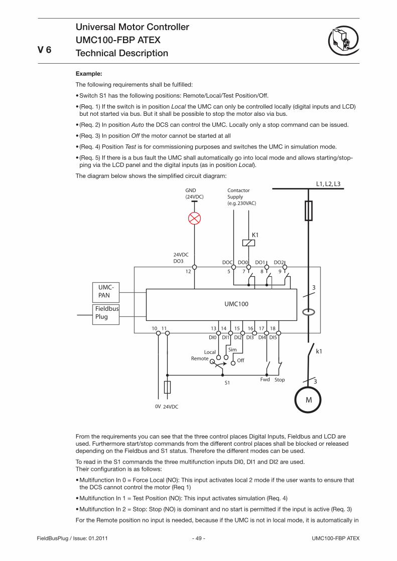
- 49 - UMC100-FBP ATEX
Universal Motor ControllerUMC100-FBP ATEXTechnical Description
V 6
FieldBusPlug / Issue: 01.2011
Example:
The following requirements shall be fulfilled:
Switch S1 has the following positions: Remote/Local/Test Position/Off.
(Req. 1) If the switch is in position Local the UMC can only be controlled locally (digital inputs and LCD) but not started via bus. But it shall be possible to stop the motor also via bus.
(Req. 2) In position Auto the DCS can control the UMC. Locally only a stop command can be issued.
(Req. ) In position Off the motor cannot be started at all
(Req. 4) Position Test is for commissioning purposes and switches the UMC in simulation mode.
(Req. 5) If there is a bus fault the UMC shall automatically go into local mode and allows starting/stop-ping via the LCD panel and the digital inputs (as in position Local).
The diagram below shows the simplified circuit diagram:L1, L2, L3
3
ContactorSupply(e.g. 230VAC)
K1
k1
DOC DO0 DO1 DO2
24VDC
10 11
5 7 8 9
24VDCDO3
12
13 14 15 16 17 18
DI0 DI1 DI2 DI3 DI4 DI5
UMC100
UMC-PAN
FieldbusPlug
0V
Fwd StopS1
GND(24VDC)
M
3
RemoteLocal Sim
Off
From the requirements you can see that the three control places Digital Inputs, Fieldbus and LCD are used. Furthermore start/stop commands from the different control places shall be blocked or released depending on the Fieldbus and S1 status. Therefore the different modes can be used.
To read in the S1 commands the three multifunction inputs DI0, DI1 and DI2 are used. Their configuration is as follows:
Multifunction In 0 = Force Local (NO): This input activates local 2 mode if the user wants to ensure that the DCS cannot control the motor (Req 1)
Multifunction In 1 = Test Position (NO): This input activates simulation (Req. 4)
Multifunction In 2 = Stop: Stop (NO) is dominant and no start is permitted if the input is active (Req. )
For the Remote position no input is needed, because if the UMC is not in local mode, it is automatically in
•
•
•
•
•
•
•
•
•
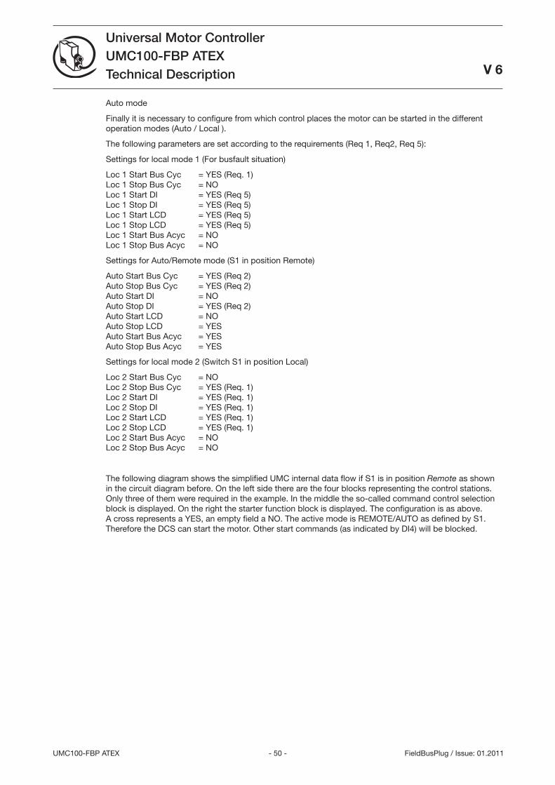
- 50 -UMC100-FBP ATEX
Universal Motor ControllerUMC100-FBP ATEXTechnical Description
V 6
FieldBusPlug / Issue: 01.2011
Auto mode
Finally it is necessary to configure from which control places the motor can be started in the different operation modes (Auto / Local ).
The following parameters are set according to the requirements (Req 1, Req2, Req 5):
Settings for local mode 1 (For busfault situation)
Loc 1 Start Bus Cyc = YES (Req. 1) Loc 1 Stop Bus Cyc = NO Loc 1 Start DI = YES (Req 5) Loc 1 Stop DI = YES (Req 5) Loc 1 Start LCD = YES (Req 5) Loc 1 Stop LCD = YES (Req 5) Loc 1 Start Bus Acyc = NO Loc 1 Stop Bus Acyc = NO
Settings for Auto/Remote mode (S1 in position Remote)
Auto Start Bus Cyc = YES (Req 2) Auto Stop Bus Cyc = YES (Req 2) Auto Start DI = NO Auto Stop DI = YES (Req 2) Auto Start LCD = NO Auto Stop LCD = YES Auto Start Bus Acyc = YES Auto Stop Bus Acyc = YES
Settings for local mode 2 (Switch S1 in position Local)
Loc 2 Start Bus Cyc = NO Loc 2 Stop Bus Cyc = YES (Req. 1) Loc 2 Start DI = YES (Req. 1) Loc 2 Stop DI = YES (Req. 1) Loc 2 Start LCD = YES (Req. 1) Loc 2 Stop LCD = YES (Req. 1) Loc 2 Start Bus Acyc = NO Loc 2 Stop Bus Acyc = NO
The following diagram shows the simplified UMC internal data flow if S1 is in position Remote as shown in the circuit diagram before. On the left side there are the four blocks representing the control stations. Only three of them were required in the example. In the middle the so-called command control selection block is displayed. On the right the starter function block is displayed. The configuration is as above. A cross represents a YES, an empty field a NO. The active mode is REMOTE/AUTO as defined by S1. Therefore the DCS can start the motor. Other start commands (as indicated by DI4) will be blocked.
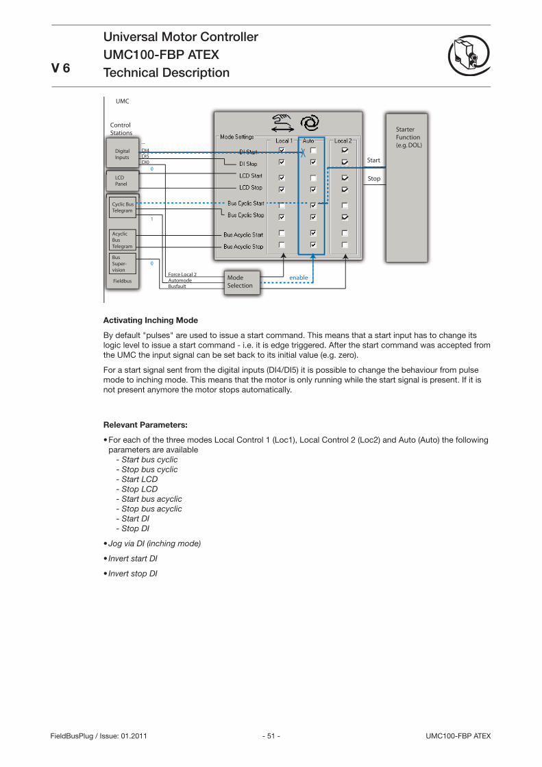
- 51 - UMC100-FBP ATEX
Universal Motor ControllerUMC100-FBP ATEXTechnical DescriptionV 6
FieldBusPlug / Issue: 01.2011
ControlStations
BusfaultAutomodeForce Local 2
ModeSelection
enable
StarterFunction(e.g. DOL)
Start
Stop
UMC
DI4DI5DI0
LCDPanel
DigitalInputs
Cyclic BusTelegram
AcyclicBusTelegram
BusSuper-vision
...
Fieldbus
0
1
0
Activating Inching Mode
By default pulses are used to issue a start command. This means that a start input has to change its logic level to issue a start command - i.e. it is edge triggered. After the start command was accepted from the UMC the input signal can be set back to its initial value (e.g. zero).
For a start signal sent from the digital inputs (DI4/DI5) it is possible to change the behaviour from pulse mode to inching mode. This means that the motor is only running while the start signal is present. If it is not present anymore the motor stops automatically.
Relevant Parameters:
For each of the three modes Local Control 1 (Loc1), Local Control 2 (Loc2) and Auto (Auto) the following parameters are available - Start bus cyclic - Stop bus cyclic - Start LCD - Stop LCD - Start bus acyclic - Stop bus acyclic - Start DI - Stop DI
Jog via DI (inching mode)
Invert start DI
Invert stop DI
•
•
•
•
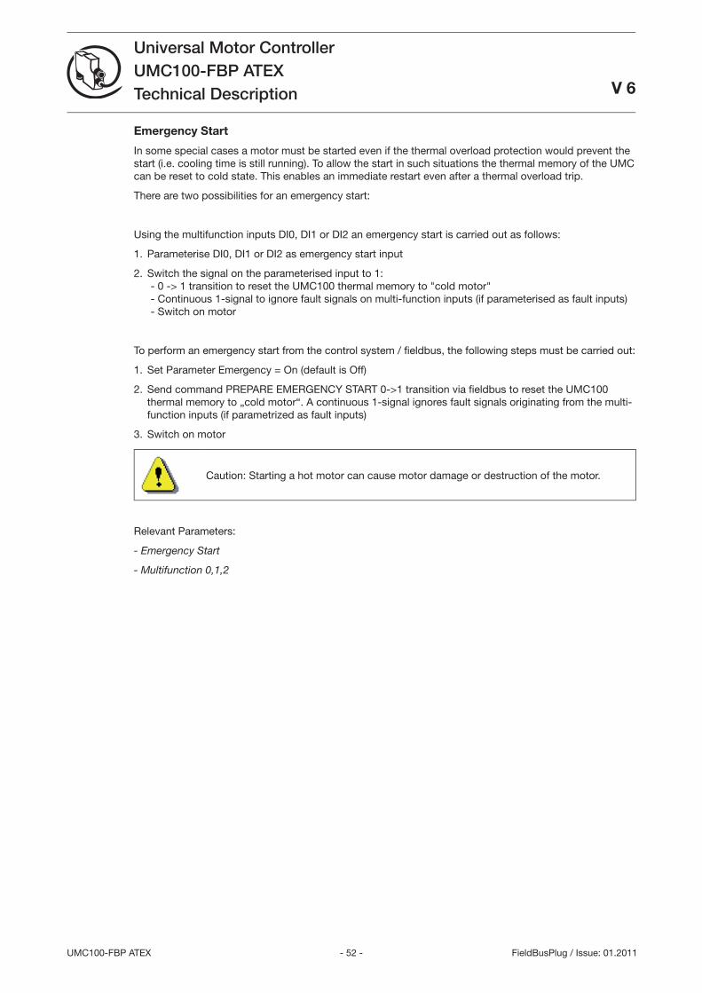
- 52 -UMC100-FBP ATEX
Universal Motor ControllerUMC100-FBP ATEXTechnical Description V 6
FieldBusPlug / Issue: 01.2011
Emergency Start
In some special cases a motor must be started even if the thermal overload protection would prevent the start (i.e. cooling time is still running). To allow the start in such situations the thermal memory of the UMC can be reset to cold state. This enables an immediate restart even after a thermal overload trip.
There are two possibilities for an emergency start:
Using the multifunction inputs DI0, DI1 or DI2 an emergency start is carried out as follows:
Parameterise DI0, DI1 or DI2 as emergency start input
Switch the signal on the parameterised input to 1: - 0 -> 1 transition to reset the UMC100 thermal memory to cold motor - Continuous 1-signal to ignore fault signals on multi-function inputs (if parameterised as fault inputs) - Switch on motor
To perform an emergency start from the control system / fi eldbus, the following steps must be carried out:
Set Parameter Emergency = On (default is Off)
Send command PREPARE EMERGENCY START 0->1 transition via fi eldbus to reset the UMC100 thermal memory to „cold motor“. A continuous 1-signal ignores fault signals originating from the multi-function inputs (if parametrized as fault inputs)
Switch on motor
Caution: Starting a hot motor can cause motor damage or destruction of the motor.
Relevant Parameters:
- Emergency Start
- Multifunction 0,1,2
1.
2.
1.
2.
.
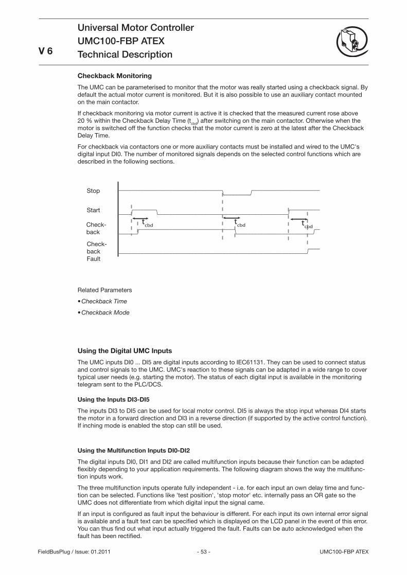
- 5 - UMC100-FBP ATEX
Universal Motor ControllerUMC100-FBP ATEXTechnical Description
V 6
FieldBusPlug / Issue: 01.2011
Checkback Monitoring
The UMC can be parameterised to monitor that the motor was really started using a checkback signal. By default the actual motor current is monitored. But it is also possible to use an auxiliary contact mounted on the main contactor.
If checkback monitoring via motor current is active it is checked that the measured current rose above 20 % within the Checkback Delay Time (tcbd) after switching on the main contactor. Otherwise when the motor is switched off the function checks that the motor current is zero at the latest after the Checkback Delay Time.
For checkback via contactors one or more auxiliary contacts must be installed and wired to the UMC's digital input DI0. The number of monitored signals depends on the selected control functions which are described in the following sections.
=================================\--------/=====================
----/=======\-----------------------------------------/=========
------/==============================\------------------------/=
------------------------------------------------------------/===
tcbd
tcbd t
cbd
Related Parameters
Checkback Time
Checkback Mode
Using the Digital UMC Inputs
The UMC inputs DI0 ... DI5 are digital inputs according to IEC6111. They can be used to connect status and control signals to the UMC. UMC's reaction to these signals can be adapted in a wide range to cover typical user needs (e.g. starting the motor). The status of each digital input is available in the monitoring telegram sent to the PLC/DCS.
Using the Inputs DI3-DI5
The inputs DI to DI5 can be used for local motor control. DI5 is always the stop input whereas DI4 starts the motor in a forward direction and DI in a reverse direction (if supported by the active control function). If inching mode is enabled the stop can still be used.
Using the Multifunction Inputs DI0-DI2
The digital inputs DI0, DI1 and DI2 are called multifunction inputs because their function can be adapted flexibly depending to your application requirements. The following diagram shows the way the multifunc-tion inputs work.
The three multifunction inputs operate fully independent - i.e. for each input an own delay time and func-tion can be selected. Functions like 'test position', 'stop motor' etc. internally pass an OR gate so the UMC does not differentiate from which digital input the signal came.
If an input is configured as fault input the behaviour is different. For each input its own internal error signal is available and a fault text can be specified which is displayed on the LCD panel in the event of this error. You can thus find out what input actually triggered the fault. Faults can be auto acknowledged when the fault has been rectified.
•
•
Start
Stop
Check- back
Check- back Fault
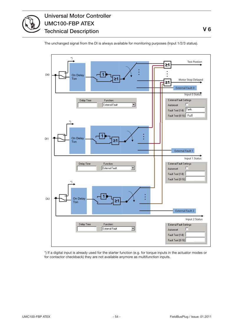
- 54 -UMC100-FBP ATEX
Universal Motor ControllerUMC100-FBP ATEXTechnical Description
V 6
FieldBusPlug / Issue: 01.2011
The unchanged signal from the DI is always available for monitoring purposes (Input 1/2/ status).
Full
*)
*)
*)
Test Postion
Motor Stop Delayed
Input 0 Status
Input 1 Status
Input 2 Status
DI0
DI1
DI2
On DelayTon
…
≥11
≥1≥1
≥1≥1
…
…On DelayTon ≥1
1≥1
1
…On DelayTon ≥1
1≥1
1
External Fault 0
External Fault 1
External Fault 2
*) If a digital input is already used for the starter function (e.g. for torque inputs in the actuator modes or for contactor checkback) they are not available anymore as multifunction inputs.
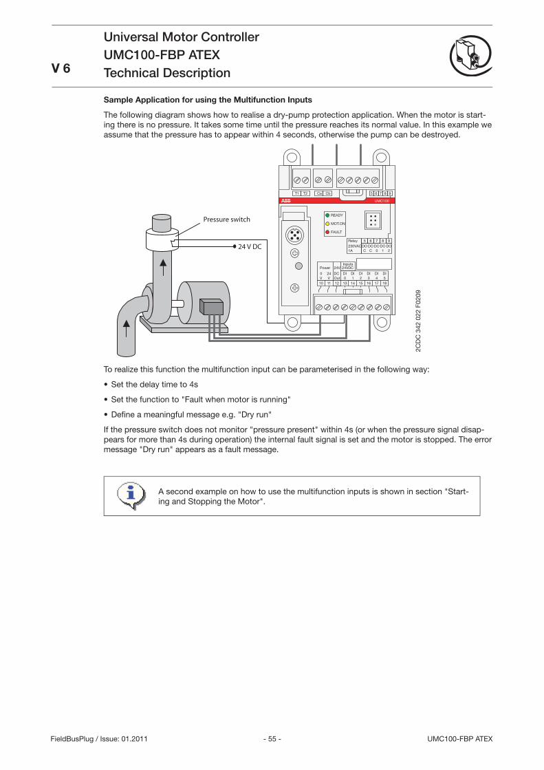
- 55 - UMC100-FBP ATEX
Universal Motor ControllerUMC100-FBP ATEXTechnical DescriptionV 6
FieldBusPlug / Issue: 01.2011
Sample Application for using the Multifunction Inputs
The following diagram shows how to realise a dry-pump protection application. When the motor is start-ing there is no pressure. It takes some time until the pressure reaches its normal value. In this example we assume that the pressure has to appear within 4 seconds, otherwise the pump can be destroyed.
24 V DC
181716151413121110
DIDIDIDIDIDI
24V
240543210OutVV
Power
T1
8DO1
7DO0
6DOC
5DOC
9DO2
8765 9T2 Ca Cb
UMC100
READY
MOT.ON
FAULT
Relay230VAC1A
Inputs24VDC
DC
Pressure switch
2CD
C 3
42 0
22 F
0209
To realize this function the multifunction input can be parameterised in the following way:
Set the delay time to 4s
Set the function to Fault when motor is running
Defi ne a meaningful message e.g. Dry run
If the pressure switch does not monitor pressure present within 4s (or when the pressure signal disap-pears for more than 4s during operation) the internal fault signal is set and the motor is stopped. The error message Dry run appears as a fault message.
A second example on how to use the multifunction inputs is shown in section Start-ing and Stopping the Motor.
•
•
•
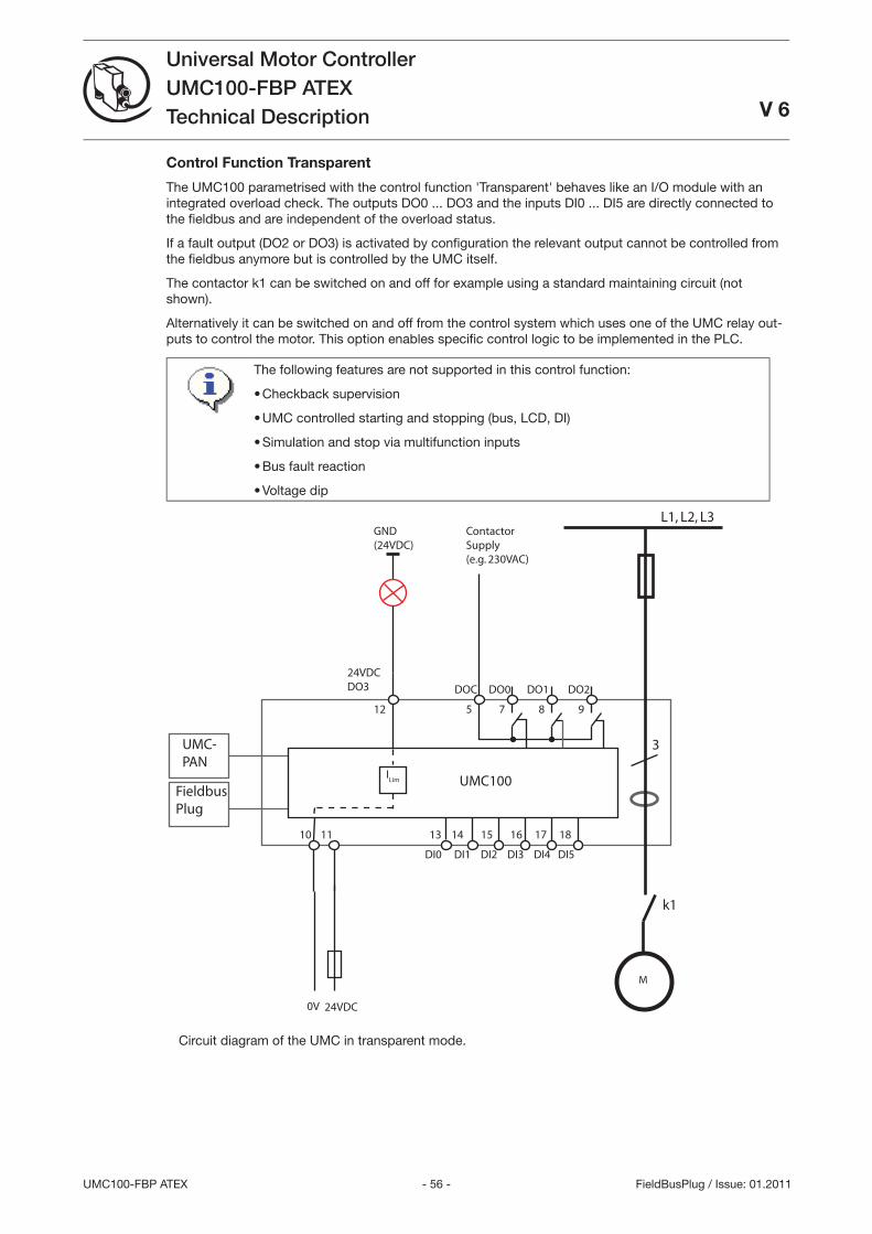
- 56 -UMC100-FBP ATEX
Universal Motor ControllerUMC100-FBP ATEXTechnical Description V 6
FieldBusPlug / Issue: 01.2011
Control Function Transparent
The UMC100 parametrised with the control function 'Transparent' behaves like an I/O module with an integrated overload check. The outputs DO0 ... DO and the inputs DI0 ... DI5 are directly connected to the fi eldbus and are independent of the overload status.
If a fault output (DO2 or DO) is activated by confi guration the relevant output cannot be controlled from the fi eldbus anymore but is controlled by the UMC itself.
The contactor k1 can be switched on and off for example using a standard maintaining circuit (not shown).
Alternatively it can be switched on and off from the control system which uses one of the UMC relay out-puts to control the motor. This option enables specifi c control logic to be implemented in the PLC.
The following features are not supported in this control function:
Checkback supervision
UMC controlled starting and stopping (bus, LCD, DI)
Simulation and stop via multifunction inputs
Bus fault reaction
Voltage dip
•
•
•
•
•
L1, L2, L3
M
3
ContactorSupply(e.g. 230VAC)
k1
DOC DO0 DO1 DO2
24VDC
10 11
5 7 8 9
24VDCDO3
12
13 14 15 16 17 18
DI0 DI1 DI2 DI3 DI4 DI5
UMC100
UMC-PAN
FieldbusPlug
0V
ILim
GND(24VDC)
Circuit diagram of the UMC in transparent mode.
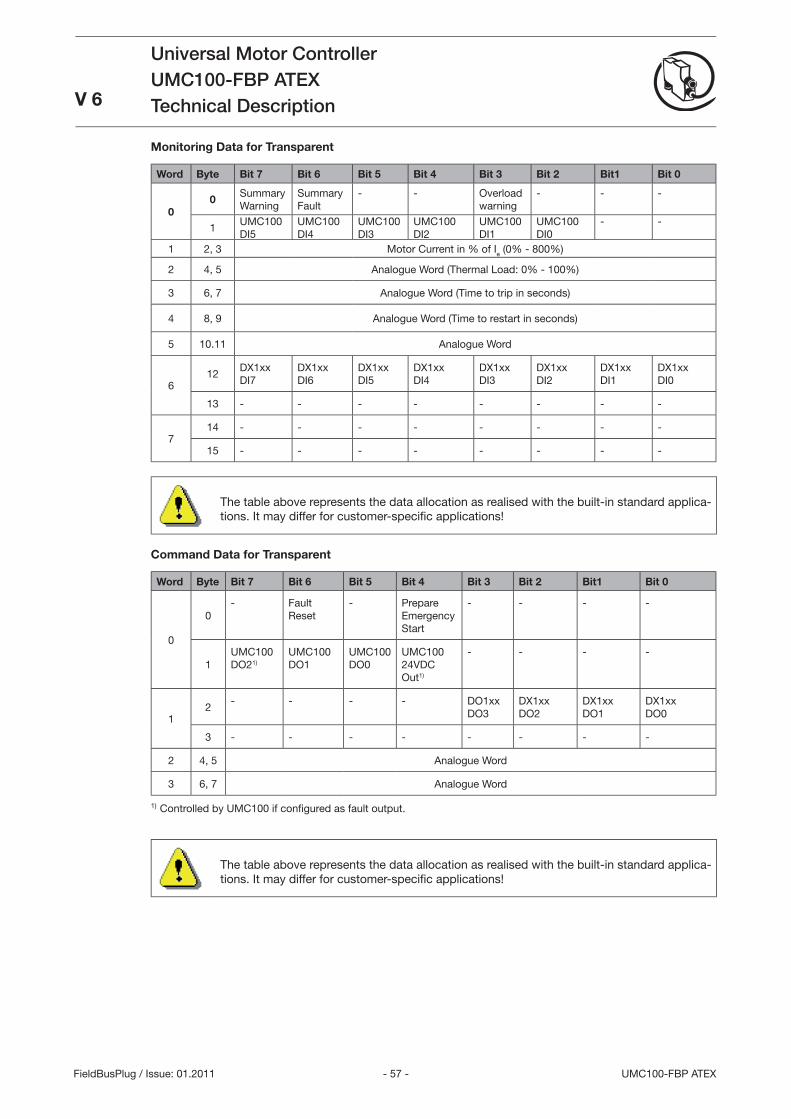
- 57 - UMC100-FBP ATEX
Universal Motor ControllerUMC100-FBP ATEXTechnical DescriptionV 6
FieldBusPlug / Issue: 01.2011
Monitoring Data for Transparent
Word Byte Bit 7 Bit 6 Bit 5 Bit 4 Bit 3 Bit 2 Bit1 Bit 0
00
Summary Warning
Summary Fault
- - Overload warning
- - -
1UMC100 DI5
UMC100 DI4
UMC100 DI
UMC100 DI2
UMC100 DI1
UMC100 DI0
- -
1 2, Motor Current in % of Ie (0% - 800%)
2 4, 5 Analogue Word (Thermal Load: 0% - 100%)
6, 7 Analogue Word (Time to trip in seconds)
4 8, 9 Analogue Word (Time to restart in seconds)
5 10.11 Analogue Word
612
DX1xx DI7
DX1xxDI6
DX1xxDI5
DX1xxDI4
DX1xxDI
DX1xxDI2
DX1xxDI1
DX1xxDI0
1 - - - - - - - -
714 - - - - - - - -
15 - - - - - - - -
The table above represents the data allocation as realised with the built-in standard applica-tions. It may differ for customer-specifi c applications!
Command Data for Transparent
Word Byte Bit 7 Bit 6 Bit 5 Bit 4 Bit 3 Bit 2 Bit1 Bit 0
0
0- Fault
Reset- Prepare
Emergency Start
- - - -
1UMC100 DO21)
UMC100 DO1
UMC100 DO0
UMC100 24VDC Out1)
- - - -
12
- - - - DO1xxDO
DX1xxDO2
DX1xxDO1
DX1xxDO0
- - - - - - - -
2 4, 5 Analogue Word
6, 7 Analogue Word
1) Controlled by UMC100 if confi gured as fault output.
The table above represents the data allocation as realised with the built-in standard applica-tions. It may differ for customer-specifi c applications!
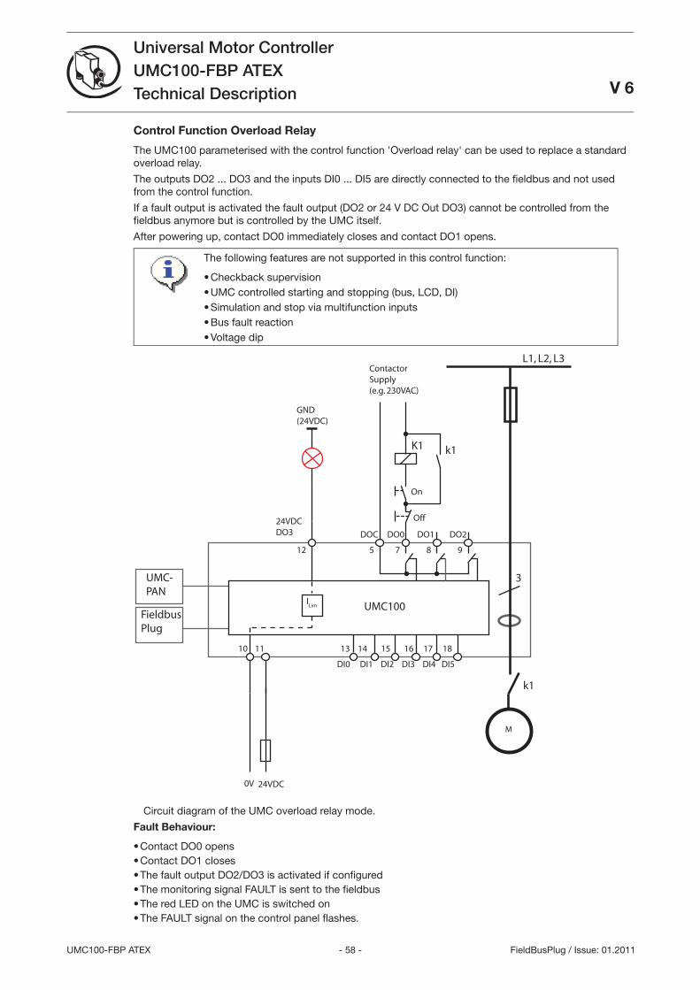
- 58 -UMC100-FBP ATEX
Universal Motor ControllerUMC100-FBP ATEXTechnical Description V 6
FieldBusPlug / Issue: 01.2011
Control Function Overload Relay
The UMC100 parameterised with the control function 'Overload relay' can be used to replace a standard overload relay.
The outputs DO2 ... DO and the inputs DI0 ... DI5 are directly connected to the fi eldbus and not used from the control function.
If a fault output is activated the fault output (DO2 or 24 V DC Out DO) cannot be controlled from the fi eldbus anymore but is controlled by the UMC itself.
After powering up, contact DO0 immediately closes and contact DO1 opens.
The following features are not supported in this control function:
Checkback supervisionUMC controlled starting and stopping (bus, LCD, DI)Simulation and stop via multifunction inputsBus fault reactionVoltage dip
•••••
L1, L2, L3
M
3
ContactorSupply(e.g. 230VAC)
K1
k1
DOC DO0 DO1 DO2
24VDC
10 11
5 7 8 9
24VDCDO3
12
13 14 15 16 17 18
DI0 DI1 DI2 DI3 DI4 DI5
UMC100
UMC-PAN
FieldbusPlug
0V
ILim
GND(24VDC)
k1
On
Off
Circuit diagram of the UMC overload relay mode.
Fault Behaviour:
Contact DO0 opensContact DO1 closesThe fault output DO2/DO is activated if confi guredThe monitoring signal FAULT is sent to the fi eldbusThe red LED on the UMC is switched onThe FAULT signal on the control panel fl ashes.
••••••
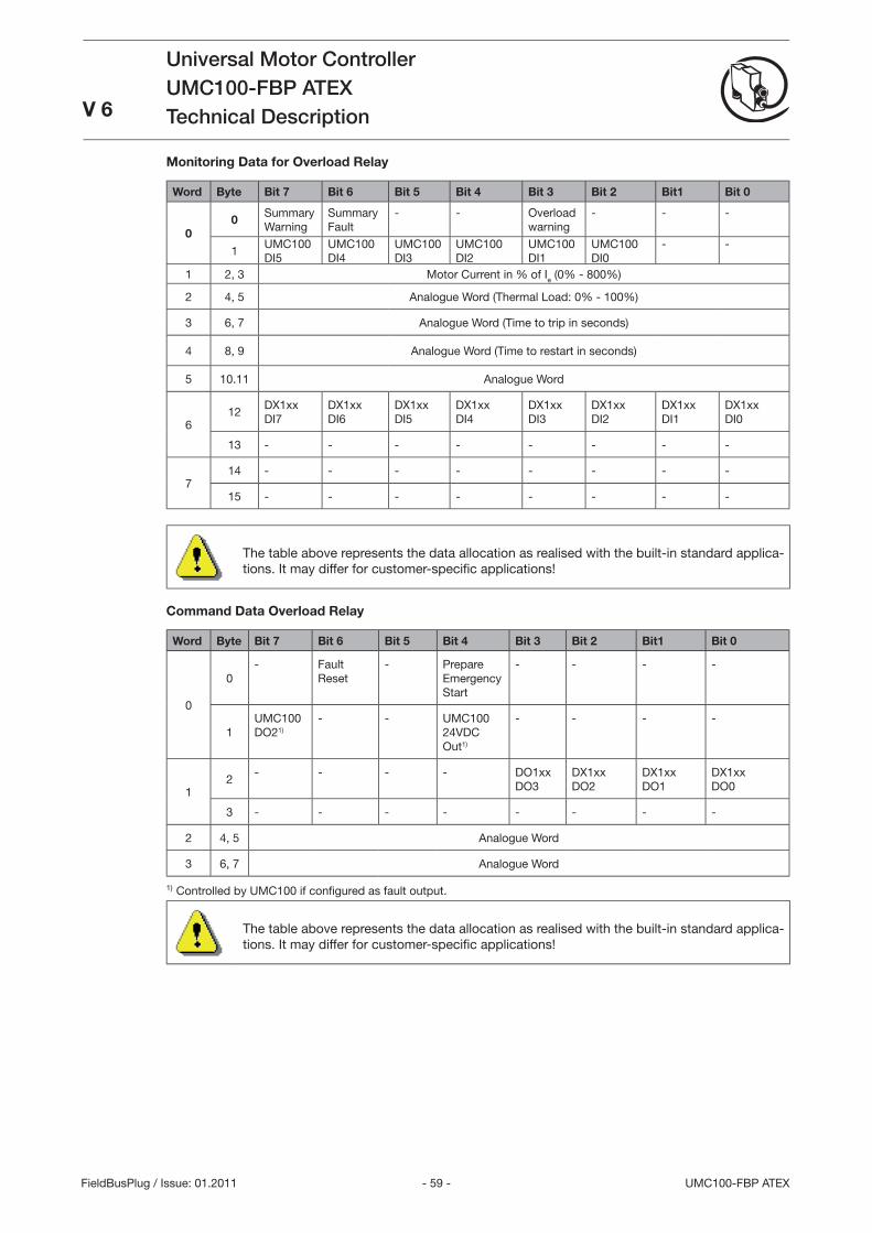
- 59 - UMC100-FBP ATEX
Universal Motor ControllerUMC100-FBP ATEXTechnical DescriptionV 6
FieldBusPlug / Issue: 01.2011
Monitoring Data for Overload Relay
Word Byte Bit 7 Bit 6 Bit 5 Bit 4 Bit 3 Bit 2 Bit1 Bit 0
00
Summary Warning
Summary Fault
- - Overload warning
- - -
1UMC100 DI5
UMC100 DI4
UMC100 DI
UMC100 DI2
UMC100 DI1
UMC100 DI0
- -
1 2, Motor Current in % of Ie (0% - 800%)
2 4, 5 Analogue Word (Thermal Load: 0% - 100%)
6, 7 Analogue Word (Time to trip in seconds)
4 8, 9 Analogue Word (Time to restart in seconds)
5 10.11 Analogue Word
612
DX1xx DI7
DX1xxDI6
DX1xxDI5
DX1xxDI4
DX1xxDI
DX1xxDI2
DX1xxDI1
DX1xxDI0
1 - - - - - - - -
714 - - - - - - - -
15 - - - - - - - -
The table above represents the data allocation as realised with the built-in standard applica-tions. It may differ for customer-specifi c applications!
Command Data Overload Relay
Word Byte Bit 7 Bit 6 Bit 5 Bit 4 Bit 3 Bit 2 Bit1 Bit 0
0
0- Fault
Reset- Prepare
Emergency Start
- - - -
1UMC100 DO21)
- - UMC100 24VDC Out1)
- - - -
12
- - - - DO1xxDO
DX1xxDO2
DX1xxDO1
DX1xxDO0
- - - - - - - -
2 4, 5 Analogue Word
6, 7 Analogue Word
1) Controlled by UMC100 if confi gured as fault output.
The table above represents the data allocation as realised with the built-in standard applica-tions. It may differ for customer-specifi c applications!
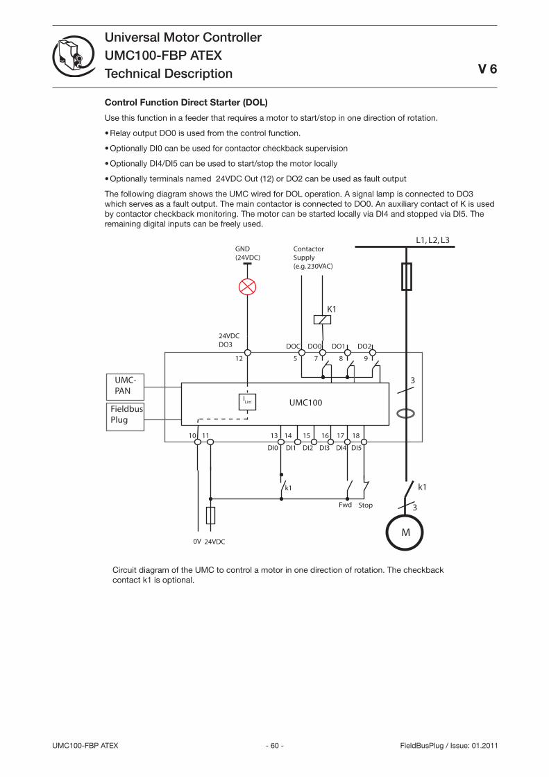
- 60 -UMC100-FBP ATEX
Universal Motor ControllerUMC100-FBP ATEXTechnical Description
V 6
FieldBusPlug / Issue: 01.2011
Control Function Direct Starter (DOL)
Use this function in a feeder that requires a motor to start/stop in one direction of rotation.
Relay output DO0 is used from the control function.
Optionally DI0 can be used for contactor checkback supervision
Optionally DI4/DI5 can be used to start/stop the motor locally
Optionally terminals named 24VDC Out (12) or DO2 can be used as fault output
The following diagram shows the UMC wired for DOL operation. A signal lamp is connected to DO which serves as a fault output. The main contactor is connected to DO0. An auxiliary contact of K is used by contactor checkback monitoring. The motor can be started locally via DI4 and stopped via DI5. The remaining digital inputs can be freely used.
L1, L2, L3
3
ContactorSupply(e.g. 230VAC)
K1
k1
DOC DO0 DO1 DO2
24VDC
10 11
5 7 8 9
24VDCDO3
12
13 14 15 16 17 18
DI0 DI1 DI2 DI3 DI4 DI5
UMC100
UMC-PAN
FieldbusPlug
0V
ILim
Fwd Stop
k1
GND(24VDC)
M
3
Circuit diagram of the UMC to control a motor in one direction of rotation. The checkback contact k1 is optional.
•
•
•
•
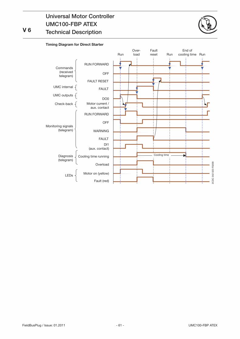
- 61 - UMC100-FBP ATEX
Universal Motor ControllerUMC100-FBP ATEXTechnical Description
V 6
FieldBusPlug / Issue: 01.2011
Timing Diagram for Direct Starter
RUN FORWARD
OFF
RUN FORWARD
OFF
FAULT RESET
FAULT
WARNING
FAULT
DO0
2CD
C 3
42 0
23 F
0209
Check-back
Commands (received telegram)
UMC outputs
Monitoring signals(telegram)
LEDs
DI1 (aux. contact)
Motor current / aux. contact
Motor on (yellow)
Run Run
Diagnosis (telegram)
UMC internal
Cooling time running
Overload
Fault (red)
Over- load
Fault reset Run
End ofcooling time
Cooling time
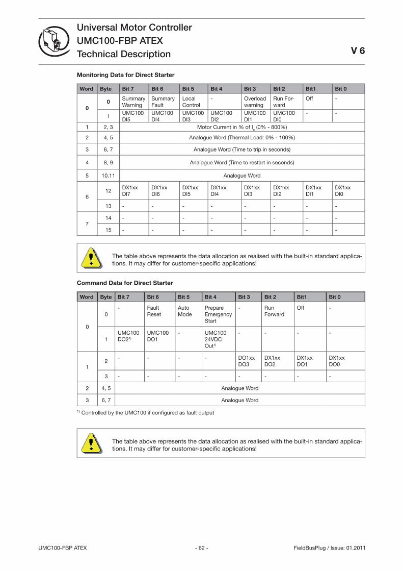
- 62 -UMC100-FBP ATEX
Universal Motor ControllerUMC100-FBP ATEXTechnical Description V 6
FieldBusPlug / Issue: 01.2011
Monitoring Data for Direct Starter
Word Byte Bit 7 Bit 6 Bit 5 Bit 4 Bit 3 Bit 2 Bit1 Bit 0
00
Summary Warning
Summary Fault
Local Control
- Overload warning
Run For-ward
Off -
1UMC100 DI5
UMC100 DI4
UMC100 DI
UMC100 DI2
UMC100 DI1
UMC100 DI0
- -
1 2, Motor Current in % of Ie (0% - 800%)
2 4, 5 Analogue Word (Thermal Load: 0% - 100%)
6, 7 Analogue Word (Time to trip in seconds)
4 8, 9 Analogue Word (Time to restart in seconds)
5 10.11 Analogue Word
612
DX1xx DI7
DX1xxDI6
DX1xxDI5
DX1xxDI4
DX1xxDI
DX1xxDI2
DX1xxDI1
DX1xxDI0
1 - - - - - - - -
714 - - - - - - - -
15 - - - - - - - -
The table above represents the data allocation as realised with the built-in standard applica-tions. It may differ for customer-specifi c applications!
Command Data for Direct Starter
Word Byte Bit 7 Bit 6 Bit 5 Bit 4 Bit 3 Bit 2 Bit1 Bit 0
0
0- Fault
ResetAuto Mode
Prepare Emergency Start
- Run Forward
Off -
1UMC100 DO21)
UMC100 DO1
- UMC100 24VDC Out1)
- - - -
12
- - - - DO1xxDO
DX1xxDO2
DX1xxDO1
DX1xxDO0
- - - - - - - -
2 4, 5 Analogue Word
6, 7 Analogue Word
1) Controlled by the UMC100 if confi gured as fault output
The table above represents the data allocation as realised with the built-in standard applica-tions. It may differ for customer-specifi c applications!
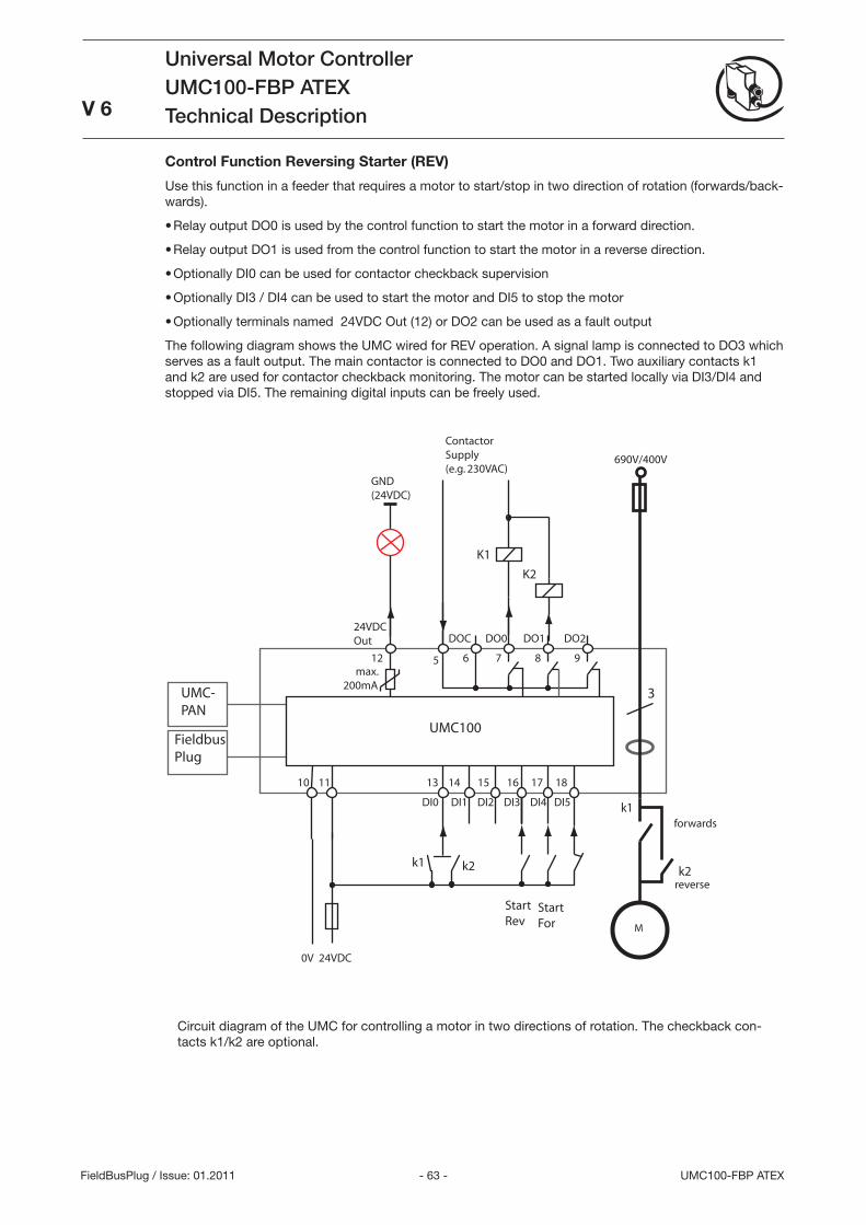
- 6 - UMC100-FBP ATEX
Universal Motor ControllerUMC100-FBP ATEXTechnical Description
V 6
FieldBusPlug / Issue: 01.2011
Control Function Reversing Starter (REV)
Use this function in a feeder that requires a motor to start/stop in two direction of rotation (forwards/back-wards).
Relay output DO0 is used by the control function to start the motor in a forward direction.
Relay output DO1 is used from the control function to start the motor in a reverse direction.
Optionally DI0 can be used for contactor checkback supervision
Optionally DI / DI4 can be used to start the motor and DI5 to stop the motor
Optionally terminals named 24VDC Out (12) or DO2 can be used as a fault output
The following diagram shows the UMC wired for REV operation. A signal lamp is connected to DO which serves as a fault output. The main contactor is connected to DO0 and DO1. Two auxiliary contacts k1 and k2 are used for contactor checkback monitoring. The motor can be started locally via DI/DI4 and stopped via DI5. The remaining digital inputs can be freely used.
M
3
DOC DO0 DO1 DO2
24VDC
10 11
6 7 8 9
24VDCOut
12
13 14 15 16 17 18
DI0 DI1 DI2 DI3 DI4 DI5
UMC100
UMC-PAN
FieldbusPlug
0V
GND(24VDC)
690V/400V
5
reverse
max.200mA
StartFor
StartRev
ContactorSupply(e.g. 230VAC)
K1
K2
k2
k1forwards
k1 k2
Circuit diagram of the UMC for controlling a motor in two directions of rotation. The checkback con-tacts k1/k2 are optional.
•
•
•
•
•
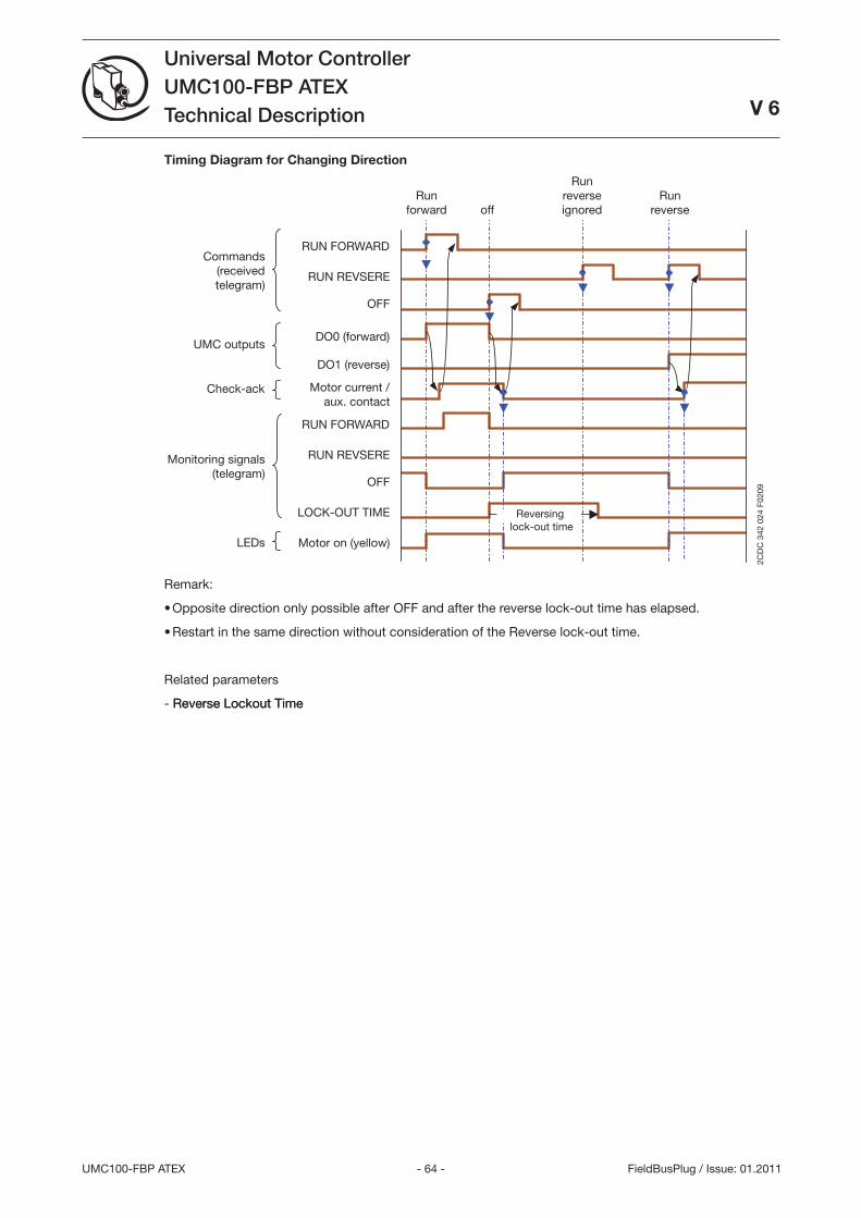
- 64 -UMC100-FBP ATEX
Universal Motor ControllerUMC100-FBP ATEXTechnical Description
V 6
FieldBusPlug / Issue: 01.2011
Timing Diagram for Changing Direction
RUN REVSERE
RUN FORWARD
OFF
OFF
RUN REVSERE
RUN FORWARD
Reversing lock-out time
2CD
C 3
42 0
24 F
0209
Check-ack
Commands (received telegram)
UMC outputs
Monitoring signals(telegram)
LEDs
DO1 (reverse)
Motor current / aux. contact
Motor on (yellow)
Run forward
LOCK-OUT TIME
DO0 (forward)
Run reverse ignored
Run reverse off
Remark:
Opposite direction only possible after OFF and after the reverse lock-out time has elapsed.
Restart in the same direction without consideration of the Reverse lock-out time.
Related parameters
- Reverse Lockout TimeReverse Lockout Time
•
•
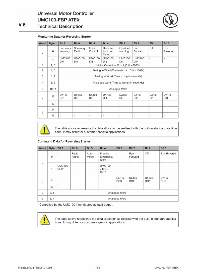
- 65 - UMC100-FBP ATEX
Universal Motor ControllerUMC100-FBP ATEXTechnical DescriptionV 6
FieldBusPlug / Issue: 01.2011
Monitoring Data for Reversing Starter
Word Byte Bit 7 Bit 6 Bit 5 Bit 4 Bit 3 Bit 2 Bit1 Bit 0
00
Summary Warning
Summary Fault
Local Control
Reverse Lockout Time
Overload warning
Run Forward
Off Run Reverse
1UMC100 DI5
UMC100 DI4
UMC100 DI
UMC100 DI2
UMC100 DI1
UMC100 DI0
- -
1 2, Motor Current in % of Ie (0% - 800%)
2 4, 5 Analogue Word (Thermal Load: 0% - 100%)
6, 7 Analogue Word (Time to trip in seconds)
4 8, 9 Analogue Word (Time to restart in seconds)
5 10.11 Analogue Word
612
DX1xx DI7
DX1xxDI6
DX1xxDI5
DX1xxDI4
DX1xxDI
DX1xxDI2
DX1xxDI1
DX1xxDI0
1 - - - - - - - -
714 - - - - - - - -
15 - - - - - - - -
The table above represents the data allocation as realised with the built-in standard applica-tions. It may differ for customer-specifi c applications!
Command Data for Reversing Starter
Word Byte Bit 7 Bit 6 Bit 5 Bit 4 Bit 3 Bit 2 Bit1 Bit 0
0
0- Fault
ResetAuto Mode
Prepare Emergency Start
- Run Forward
Off Run Reverse
1UMC100 DO21)
- - UMC100 24VDC Out1)
- - - -
12
- - - - DO1xxDO
DX1xxDO2
DX1xxDO1
DX1xxDO0
- - - - - - - -
2 4, 5 Analogue Word
6, 7 Analogue Word
1) Controlled by the UMC100 if confi gured as fault output.
The table above represents the data allocation as realised with the built-in standard applica-tions. It may differ for customer-specifi c applications!
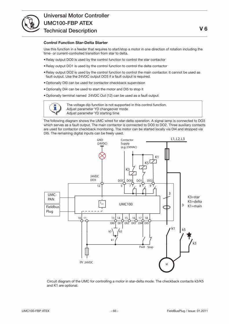
- 66 -UMC100-FBP ATEX
Universal Motor ControllerUMC100-FBP ATEXTechnical Description V 6
FieldBusPlug / Issue: 01.2011
Control Function Star-Delta Starter
Use this function in a feeder that requires to start/stop a motor in one direction of rotation including the time- or current-controlled transition from star to delta.
Relay output DO0 is used by the control function to control the star contactor
Relay output DO1 is used by the control function to control the delta contactor
Relay output DO2 is used by the control function to control the main contactor. It cannot be used as fault output. Use the 24VDC output DO if a fault output is required.
Optionally DI0 can be used for contactor checkback supervision
Optionally DI4 can be used to start the motor and DI5 to stop it
Optionally terminal named 24VDC Out (12) can be used as a fault output
The voltage dip function is not supported in this control function.Adjust parameter YD changeover modeAdjust parameter YD starting time
The following diagram shows the UMC wired for star-delta operation. A signal lamp is connected to DO which serves as a fault output. The main contactor is connected to DO0 to DO2. Three auxiliary contacts are used for contactor checkback monitoring. The motor can be started locally via DI4 and stopped via DI5. The remaining digital inputs can be freely used.
L1, L2, L3
M
3
ContactorSupply(e.g. 230VAC)
K3
k3
DOC DO0 DO1 DO2
24VDC
10 11
5 7 8 9
24VDCDO3
12
13 14 15 16 17 18
DI0 DI1 DI2 DI3 DI4 DI5
UMC100
UMC-PAN
FieldbusPlug
0V
ILim
Fwd Stop
k1
GND(24VDC)
K5
K1
k5k1k5k3
3
K3=starK5=deltaK1=main
Circuit diagram of the UMC for controlling a motor in star-delta mode. The checkback contacts k/K5 and K1 are optional.
•
•
•
•
•
•
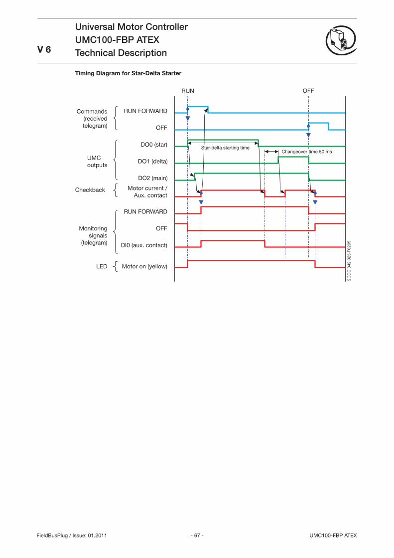
- 67 - UMC100-FBP ATEX
Universal Motor ControllerUMC100-FBP ATEXTechnical Description
V 6
FieldBusPlug / Issue: 01.2011
Timing Diagram for Star-Delta Starter
RUN FORWARD
OFF
RUN FORWARD
OFF
Checkback
Commands(receivedtelegram)
UMCoutputs
Monitoringsignals
(telegram)
LED
DO0 (star)
DO1 (delta)
Motor current /Aux. contact
DI0 (aux. contact)
Motor on (yellow)
RUN OFF
Star-delta starting timeChangeover time 50 ms
DO2 (main)
2CD
C 3
42 0
25 F
0209
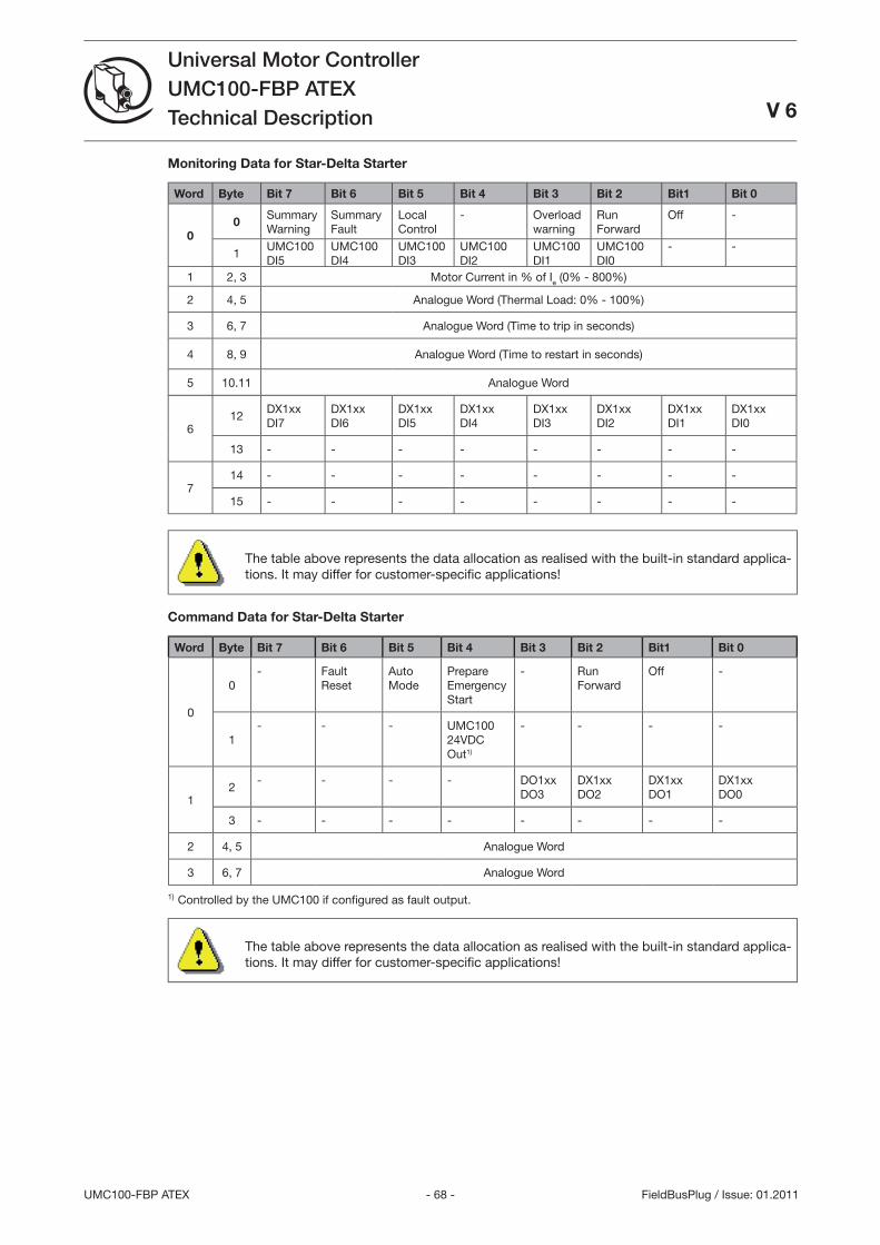
- 68 -UMC100-FBP ATEX
Universal Motor ControllerUMC100-FBP ATEXTechnical Description V 6
FieldBusPlug / Issue: 01.2011
Monitoring Data for Star-Delta Starter
Word Byte Bit 7 Bit 6 Bit 5 Bit 4 Bit 3 Bit 2 Bit1 Bit 0
00
Summary Warning
Summary Fault
Local Control
- Overload warning
Run Forward
Off -
1UMC100 DI5
UMC100 DI4
UMC100 DI
UMC100 DI2
UMC100 DI1
UMC100 DI0
- -
1 2, Motor Current in % of Ie (0% - 800%)
2 4, 5 Analogue Word (Thermal Load: 0% - 100%)
6, 7 Analogue Word (Time to trip in seconds)
4 8, 9 Analogue Word (Time to restart in seconds)
5 10.11 Analogue Word
612
DX1xx DI7
DX1xxDI6
DX1xxDI5
DX1xxDI4
DX1xxDI
DX1xxDI2
DX1xxDI1
DX1xxDI0
1 - - - - - - - -
714 - - - - - - - -
15 - - - - - - - -
The table above represents the data allocation as realised with the built-in standard applica-tions. It may differ for customer-specifi c applications!
Command Data for Star-Delta Starter
Word Byte Bit 7 Bit 6 Bit 5 Bit 4 Bit 3 Bit 2 Bit1 Bit 0
0
0- Fault
ResetAuto Mode
Prepare Emergency Start
- Run Forward
Off -
1- - - UMC100
24VDC Out1)
- - - -
12
- - - - DO1xxDO
DX1xxDO2
DX1xxDO1
DX1xxDO0
- - - - - - - -
2 4, 5 Analogue Word
6, 7 Analogue Word
1) Controlled by the UMC100 if confi gured as fault output.
The table above represents the data allocation as realised with the built-in standard applica-tions. It may differ for customer-specifi c applications!
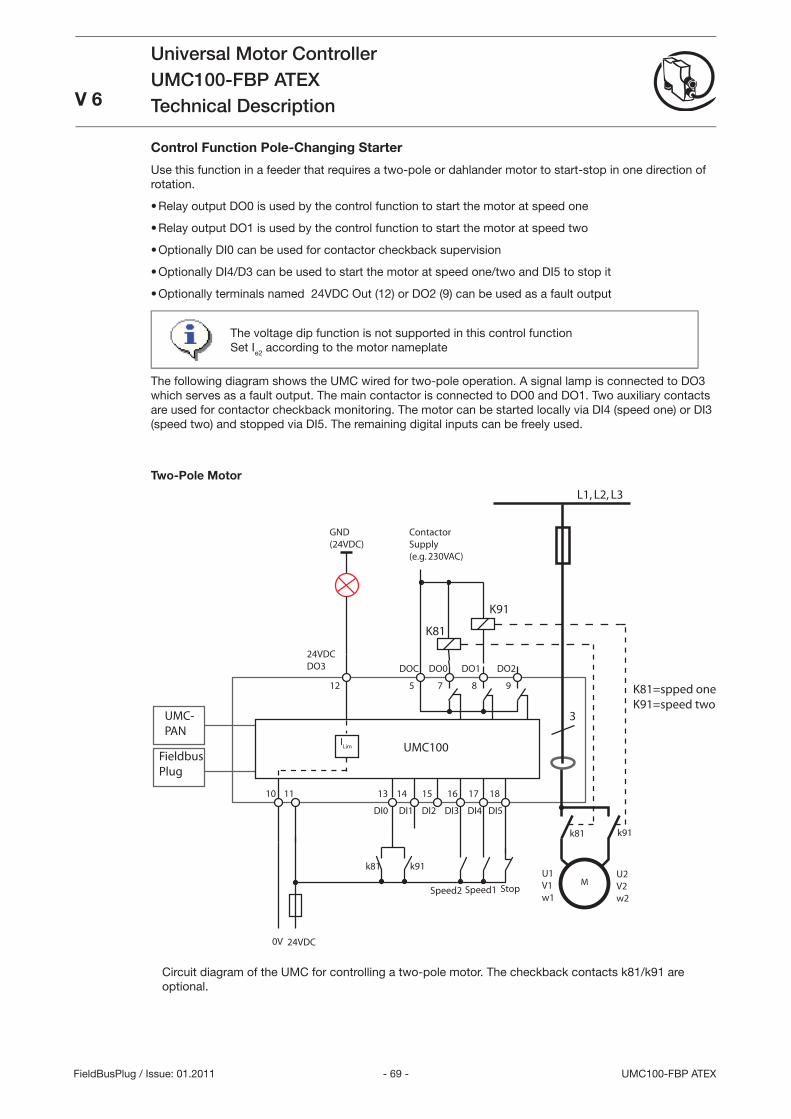
- 69 - UMC100-FBP ATEX
Universal Motor ControllerUMC100-FBP ATEXTechnical DescriptionV 6
FieldBusPlug / Issue: 01.2011
Control Function Pole-Changing Starter
Use this function in a feeder that requires a two-pole or dahlander motor to start-stop in one direction of rotation.
Relay output DO0 is used by the control function to start the motor at speed one
Relay output DO1 is used by the control function to start the motor at speed two
Optionally DI0 can be used for contactor checkback supervision
Optionally DI4/D can be used to start the motor at speed one/two and DI5 to stop it
Optionally terminals named 24VDC Out (12) or DO2 (9) can be used as a fault output
The voltage dip function is not supported in this control functionSet Ie2 according to the motor nameplate
The following diagram shows the UMC wired for two-pole operation. A signal lamp is connected to DO which serves as a fault output. The main contactor is connected to DO0 and DO1. Two auxiliary contacts are used for contactor checkback monitoring. The motor can be started locally via DI4 (speed one) or DI (speed two) and stopped via DI5. The remaining digital inputs can be freely used.
Two-Pole Motor
L1, L2, L3
M
3
ContactorSupply(e.g. 230VAC)
K81
DOC DO0 DO1 DO2
24VDC
10 11
5 7 8 9
24VDCDO3
12
13 14 15 16 17 18
DI0 DI1 DI2 DI3 DI4 DI5
UMC100
UMC-PAN
FieldbusPlug
0V
ILim
Speed1 Stop
GND(24VDC)
K91
k91k81
K81=spped oneK91=speed two
U1V1w1
U2V2w2
Speed2
k81 k91
Circuit diagram of the UMC for controlling a two-pole motor. The checkback contacts k81/k91 are optional.
•
•
•
•
•
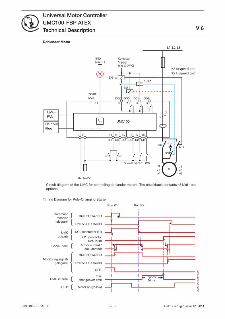
- 70 -UMC100-FBP ATEX
Universal Motor ControllerUMC100-FBP ATEXTechnical Description
V 6
FieldBusPlug / Issue: 01.2011
Dahlander Motor
L1, L2, L3
M
3
ContactorSupply(e.g. 230VAC)
K81
DOC DO0 DO1 DO2
24VDC
10 11
5 7 8 9
24VDCDO3
12
13 14 15 16 17 18
DI0 DI1 DI2 DI3 DI4 DI5
UMC100
UMC-PAN
FieldbusPlug
0V
ILim
Speed1 Stop
GND(24VDC)
K91b
k91k81
K81=speed oneK91=speed two
U1V1w1
U2V2w2
Speed2
k81
k91b
K91a
k91a
Circuit diagram of the UMC for controlling dahlander motors. The checkback contacts k81/k91 are optional.
Timing Diagram for Pole-Changing Starter
OFF
RUN FAST FORWARD
RUN FORWARD
RUN FAST FORWARD
RUN FORWARD
approx. 50 ms
2CD
C 3
42 0
26 F
0209
Check-back
Commandreceived
telegram)
UMCoutputs
Monitoring signals(telegram)
LEDs
DO1 (contactorK2a, K2b)
Motor current /aux. contact
Motor on (yellow)
Run K1
UMC internalmin.
changeover time
Run K2
DO0 (contactor K1)
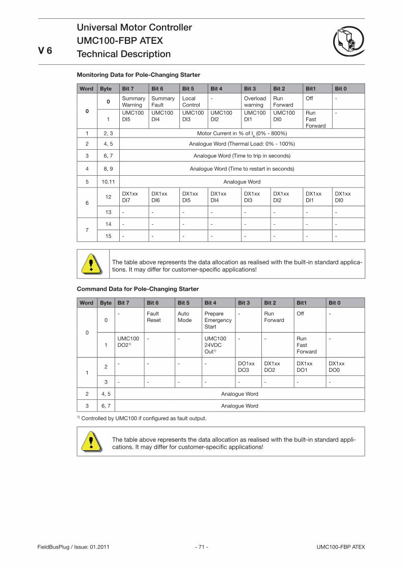
- 71 - UMC100-FBP ATEX
Universal Motor ControllerUMC100-FBP ATEXTechnical DescriptionV 6
FieldBusPlug / Issue: 01.2011
Monitoring Data for Pole-Changing Starter
Word Byte Bit 7 Bit 6 Bit 5 Bit 4 Bit 3 Bit 2 Bit1 Bit 0
0
0Summary Warning
Summary Fault
Local Control
- Overload warning
Run Forward
Off -
1UMC100 DI5
UMC100 DI4
UMC100 DI
UMC100 DI2
UMC100 DI1
UMC100 DI0
Run Fast Forward
-
1 2, Motor Current in % of Ie (0% - 800%)
2 4, 5 Analogue Word (Thermal Load: 0% - 100%)
6, 7 Analogue Word (Time to trip in seconds)
4 8, 9 Analogue Word (Time to restart in seconds)
5 10.11 Analogue Word
612
DX1xx DI7
DX1xxDI6
DX1xxDI5
DX1xxDI4
DX1xxDI
DX1xxDI2
DX1xxDI1
DX1xxDI0
1 - - - - - - - -
714 - - - - - - - -
15 - - - - - - - -
The table above represents the data allocation as realised with the built-in standard applica-tions. It may differ for customer-specifi c applications!
Command Data for Pole-Changing Starter
Word Byte Bit 7 Bit 6 Bit 5 Bit 4 Bit 3 Bit 2 Bit1 Bit 0
0
0- Fault
ResetAuto Mode
Prepare Emergency Start
- Run Forward
Off -
1UMC100 DO21)
- - UMC100 24VDC Out1)
- - Run Fast Forward
-
12
- - - - DO1xxDO
DX1xxDO2
DX1xxDO1
DX1xxDO0
- - - - - - - -
2 4, 5 Analogue Word
6, 7 Analogue Word
1) Controlled by UMC100 if confi gured as fault output.
The table above represents the data allocation as realised with the built-in standard appli-cations. It may differ for customer-specifi c applications!
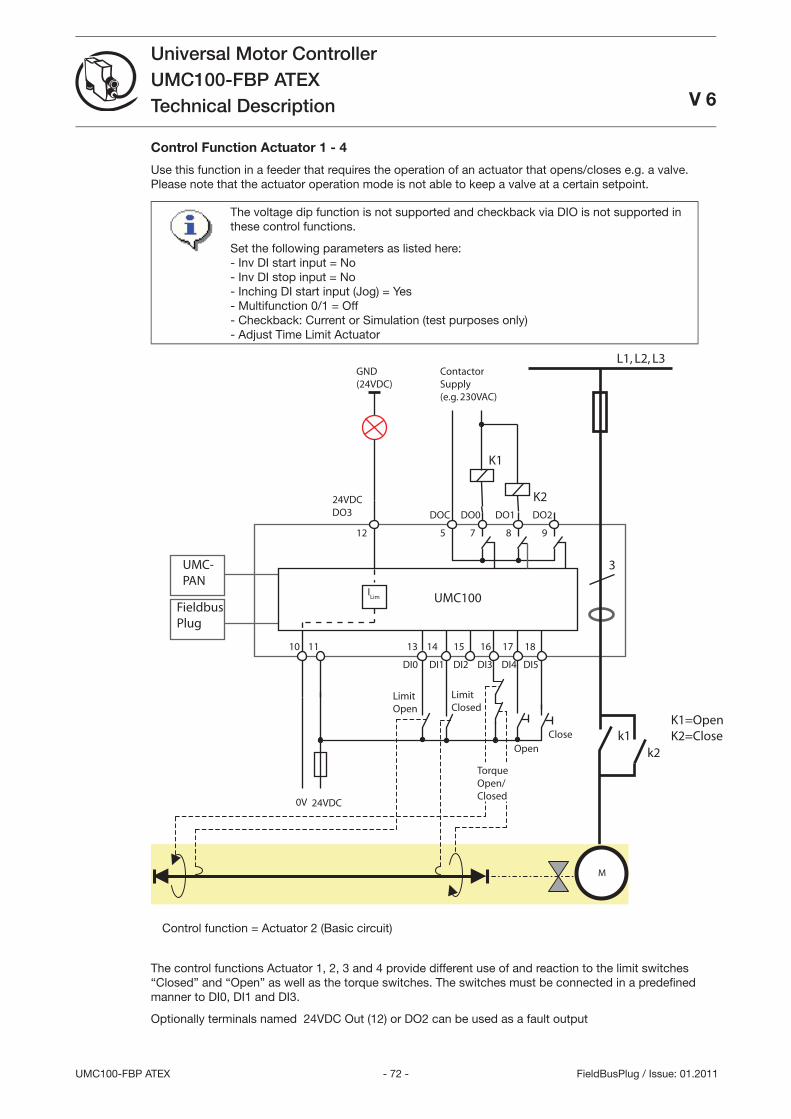
- 72 -UMC100-FBP ATEX
Universal Motor ControllerUMC100-FBP ATEXTechnical Description V 6
FieldBusPlug / Issue: 01.2011
Control Function Actuator 1 - 4
Use this function in a feeder that requires the operation of an actuator that opens/closes e.g. a valve. Please note that the actuator operation mode is not able to keep a valve at a certain setpoint.
The voltage dip function is not supported and checkback via DIO is not supported in these control functions.
Set the following parameters as listed here:- Inv DI start input = No- Inv DI stop input = No- Inching DI start input (Jog) = Yes- Multifunction 0/1 = Off- Checkback: Current or Simulation (test purposes only)- Adjust Time Limit Actuator
L1, L2, L3
3
ContactorSupply(e.g. 230VAC)
K1
DOC DO0 DO1 DO2
24VDC
10 11
5 7 8 9
24VDCDO3
12
13 14 15 16 17 18
DI0 DI1 DI2 DI3 DI4 DI5
UMC100
UMC-PAN
FieldbusPlug
0V
ILim
OpenClose
GND(24VDC)
K2
k1k2
K1=OpenK2=Close
LimitOpen
LimitClosed
M
TorqueOpen/Closed
Control function = Actuator 2 (Basic circuit)
The control functions Actuator 1, 2, and 4 provide different use of and reaction to the limit switches “Closed” and “Open” as well as the torque switches. The switches must be connected in a predefi ned manner to DI0, DI1 and DI.
Optionally terminals named 24VDC Out (12) or DO2 can be used as a fault output

- 7 - UMC100-FBP ATEX
Universal Motor ControllerUMC100-FBP ATEXTechnical Description
V 6
FieldBusPlug / Issue: 01.2011
Overview:
Control function Open <-> Closed
Torque open Limit open Limit closed Torque closed
Actuator 1 - Stop Stop -
Actuator 2 Stop Prepare Prepare Stop
Actuator - Stop Prepare Stop
Actuator 4 Stop Prepare Stop -
Acutator 1
Open and Closed position via limit switches
Usage with limit switches
DI013
24V12
DI316
DI114
Open
Torque
Open,Closed
Closed
2CD
C 3
42 0
20 F
0205
Limit switches
DI0: Motor off, start only in Closed direction
DI1: Motor off, start only in Open direction
DI: Fault: motor stops
Remark:
Torque signals are not necessary but can be used for surveillance.
After switching off the motor continues to run for some milliseconds due to its rotating mass. Adjustment of the Closed and Open limit switches is necessary to achieve the correct end positions.
•
•
Usage without torque switches
DI013
24V12
DI316
DI114
Open Closed
2CD
C 3
42 0
21 F
0205
Limit switches
DI0: Motor off, start only in Close direction
DI1: Motor off, start only in Open direction
Remark:
Connection if torque contacts are not avail-able
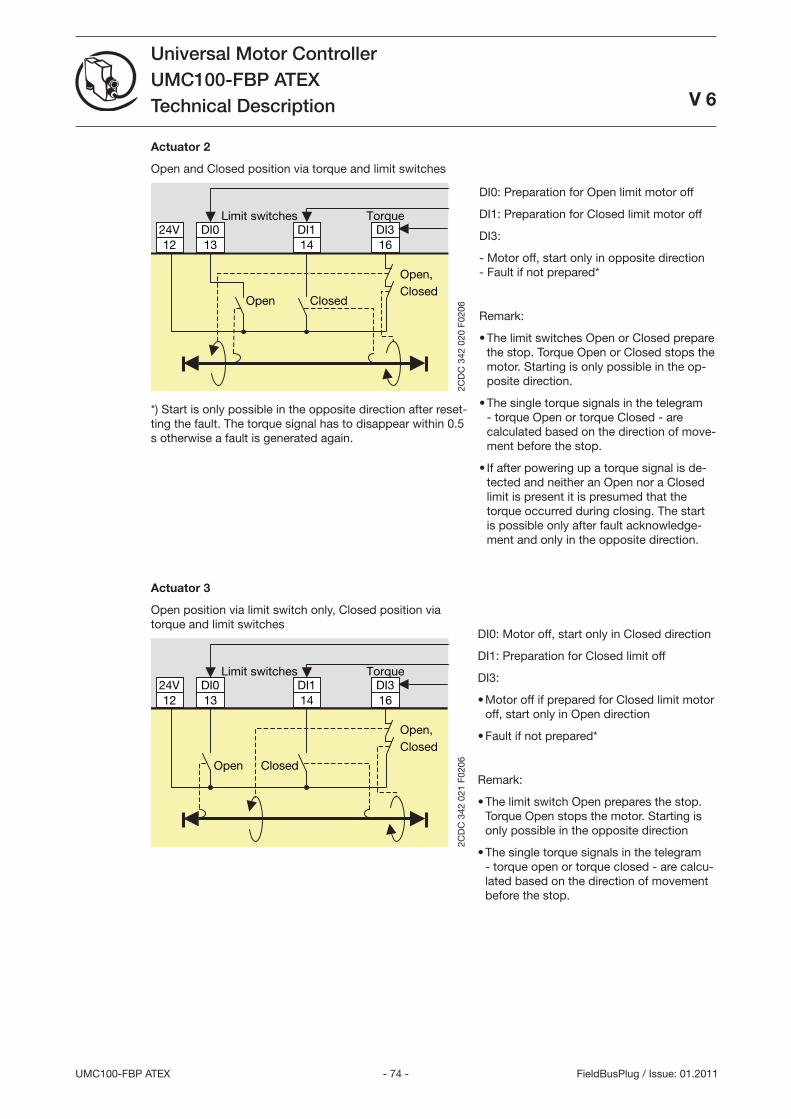
- 74 -UMC100-FBP ATEX
Universal Motor ControllerUMC100-FBP ATEXTechnical Description
V 6
FieldBusPlug / Issue: 01.2011
Actuator 2
Open and Closed position via torque and limit switches
DI013
24V12
DI316
DI114
Open
Torque
Open,Closed
Closed
2CD
C 3
42 0
20 F
0206
Limit switches
*) Start is only possible in the opposite direction after reset-ting the fault. The torque signal has to disappear within 0.5 s otherwise a fault is generated again.
DI0: Preparation for Open limit motor off
DI1: Preparation for Closed limit motor off
DI:
- Motor off, start only in opposite direction - Fault if not prepared*
Remark:
The limit switches Open or Closed prepare the stop. Torque Open or Closed stops the motor. Starting is only possible in the op-posite direction.
The single torque signals in the telegram - torque Open or torque Closed - are calculated based on the direction of move-ment before the stop.
If after powering up a torque signal is de-tected and neither an Open nor a Closed limit is present it is presumed that the torque occurred during closing. The start is possible only after fault acknowledge-ment and only in the opposite direction.
•
•
•
Actuator 3
Open position via limit switch only, Closed position via torque and limit switches
DI013
24V12
DI316
DI114
Open
Torque
Open,Closed
Closed
2CD
C 3
42 0
21 F
0206
Limit switches
DI0: Motor off, start only in Closed direction
DI1: Preparation for Closed limit off
DI:
Motor off if prepared for Closed limit motor off, start only in Open direction
Fault if not prepared*
Remark:
The limit switch Open prepares the stop. Torque Open stops the motor. Starting is only possible in the opposite direction
The single torque signals in the telegram - torque open or torque closed - are calcu-lated based on the direction of movement before the stop.
•
•
•
•
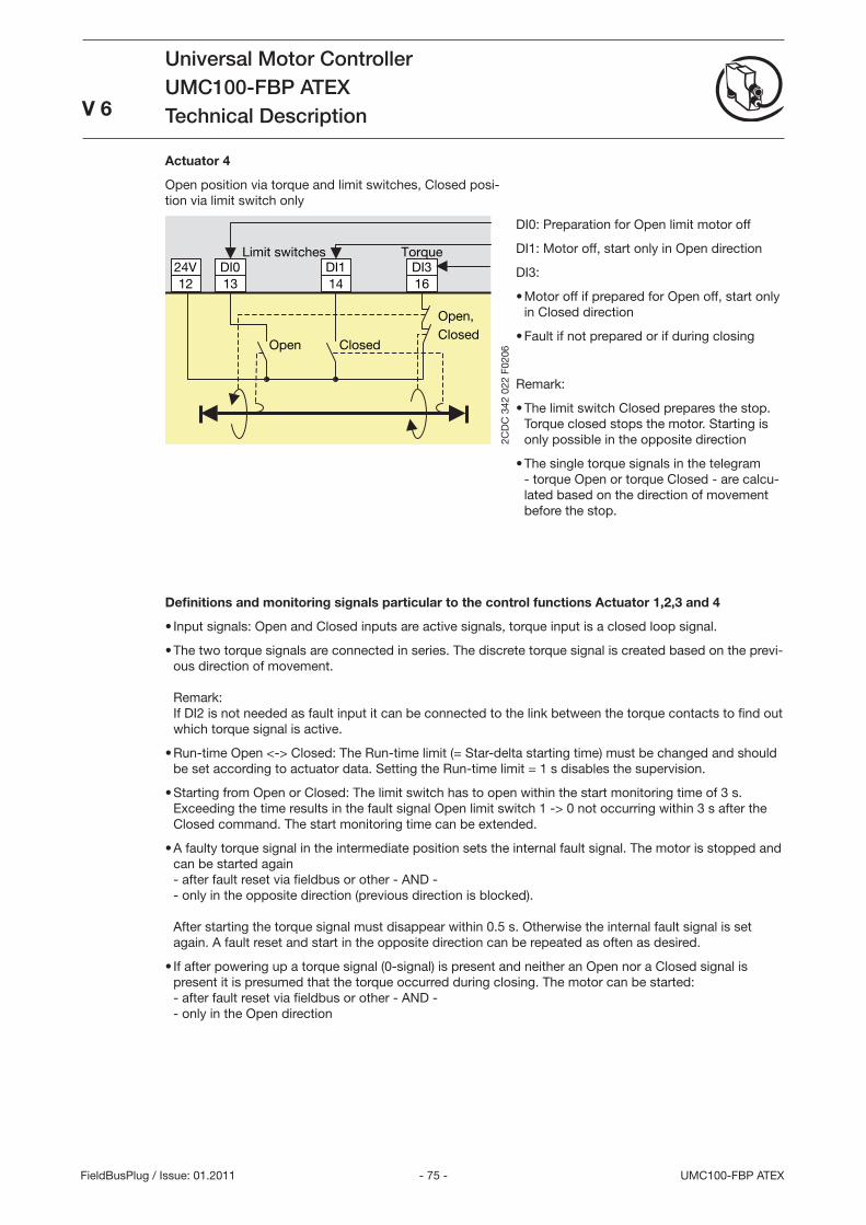
- 75 - UMC100-FBP ATEX
Universal Motor ControllerUMC100-FBP ATEXTechnical Description
V 6
FieldBusPlug / Issue: 01.2011
Actuator 4
Open position via torque and limit switches, Closed posi-tion via limit switch only
DI013
24V12
DI316
DI114
Open
Torque
Open,Closed
Closed
2CD
C 3
42 0
22 F
0206
Limit switches
DI0: Preparation for Open limit motor off
DI1: Motor off, start only in Open direction
DI:
Motor off if prepared for Open off, start only in Closed direction
Fault if not prepared or if during closing
Remark:
The limit switch Closed prepares the stop. Torque closed stops the motor. Starting is only possible in the opposite direction
The single torque signals in the telegram - torque Open or torque Closed - are calcu-lated based on the direction of movement before the stop.
•
•
•
•
Definitions and monitoring signals particular to the control functions Actuator 1,2,3 and 4
Input signals: Open and Closed inputs are active signals, torque input is a closed loop signal.
The two torque signals are connected in series. The discrete torque signal is created based on the previ-ous direction of movement. Remark: If DI2 is not needed as fault input it can be connected to the link between the torque contacts to find out which torque signal is active.
Run-time Open <-> Closed: The Run-time limit (= Star-delta starting time) must be changed and should be set according to actuator data. Setting the Run-time limit = 1 s disables the supervision.
Starting from Open or Closed: The limit switch has to open within the start monitoring time of s. Exceeding the time results in the fault signal Open limit switch 1 -> 0 not occurring within s after the Closed command. The start monitoring time can be extended.
A faulty torque signal in the intermediate position sets the internal fault signal. The motor is stopped and can be started again - after fault reset via fieldbus or other - AND - - only in the opposite direction (previous direction is blocked). After starting the torque signal must disappear within 0.5 s. Otherwise the internal fault signal is set again. A fault reset and start in the opposite direction can be repeated as often as desired.
If after powering up a torque signal (0-signal) is present and neither an Open nor a Closed signal is present it is presumed that the torque occurred during closing. The motor can be started: - after fault reset via fieldbus or other - AND - - only in the Open direction
•
•
•
•
•
•
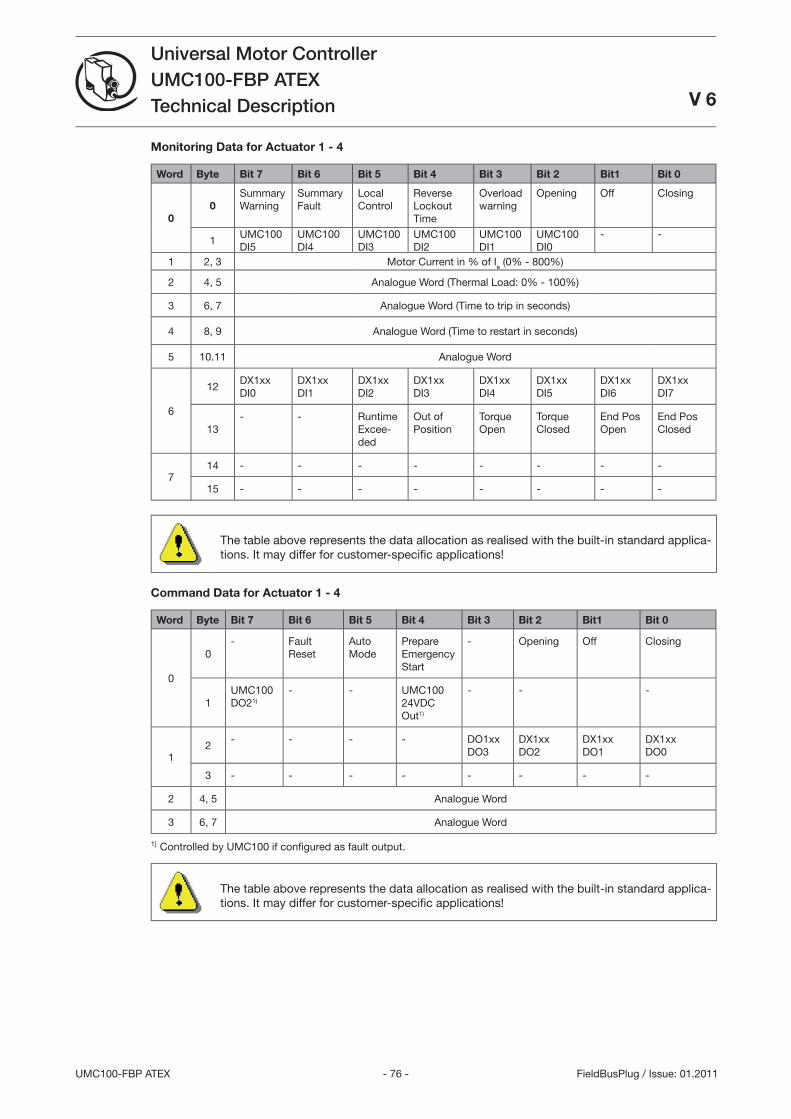
- 76 -UMC100-FBP ATEX
Universal Motor ControllerUMC100-FBP ATEXTechnical Description V 6
FieldBusPlug / Issue: 01.2011
Monitoring Data for Actuator 1 - 4
Word Byte Bit 7 Bit 6 Bit 5 Bit 4 Bit 3 Bit 2 Bit1 Bit 0
00
Summary Warning
Summary Fault
Local Control
Reverse Lockout Time
Overload warning
Opening Off Closing
1UMC100 DI5
UMC100 DI4
UMC100 DI
UMC100 DI2
UMC100 DI1
UMC100 DI0
- -
1 2, Motor Current in % of Ie (0% - 800%)
2 4, 5 Analogue Word (Thermal Load: 0% - 100%)
6, 7 Analogue Word (Time to trip in seconds)
4 8, 9 Analogue Word (Time to restart in seconds)
5 10.11 Analogue Word
6
12DX1xx DI0
DX1xxDI1
DX1xxDI2
DX1xxDI
DX1xxDI4
DX1xxDI5
DX1xxDI6
DX1xxDI7
1- - Runtime
Excee-ded
Out of Position
Torque Open
Torque Closed
End Pos Open
End Pos Closed
714 - - - - - - - -
15 - - - - - - - -
The table above represents the data allocation as realised with the built-in standard applica-tions. It may differ for customer-specifi c applications!
Command Data for Actuator 1 - 4
Word Byte Bit 7 Bit 6 Bit 5 Bit 4 Bit 3 Bit 2 Bit1 Bit 0
0
0- Fault
ResetAuto Mode
Prepare Emergency Start
- Opening Off Closing
1UMC100 DO21)
- - UMC100 24VDC Out1)
- - -
12
- - - - DO1xxDO
DX1xxDO2
DX1xxDO1
DX1xxDO0
- - - - - - - -
2 4, 5 Analogue Word
6, 7 Analogue Word
1) Controlled by UMC100 if confi gured as fault output.
The table above represents the data allocation as realised with the built-in standard applica-tions. It may differ for customer-specifi c applications!
- 77 - UMC100-FBP ATEX
Universal Motor ControllerUMC100-FBP ATEXTechnical DescriptionV 6
FieldBusPlug / Issue: 01.2011
6 Confi guring the Fieldbus CommunicationThe UMC can be integrated into different fi eldbus networks with the help of a FieldBusPlug. FieldBbusPlugs exist presently for PROFIBUS (PDP22 / PDQ22), DeviceNet(DNP21), Modbus (MRP21) and CANopen (COP21).
Since the fi eldbuses and the various fi eldbus master confi guration tools are very different no common integration procedure can be described here. In general the following generic steps are usually necessary:
Make the UMC known to the tool e.g. by importing the device description fi le (GSD, EDS)
Create a network and insert nodes like the UMC as required
Set the UMC parameters according to your needs (if parameterisation from within the system is re-quired)
Make the I/O signals available in your programming tool (e.g. a IEC6111 based tool)
To use the UMC in a fi eldbus network the following parameters should be considered.
Setting the Bus Address
The bus address can be adjusted with the help of the UMC LCD panel. The UMC allows an address to be set between 000 and 255. But there are different limitations depending on the fi eldbus in use. Setting the address to 255 means that the UMC will take over the address from a connected FieldBusPlug.
PROFIBUS: Use addresses from 2 ...125 only.
DeviceNet: 2-64
Modbus: With the bus address you also select the baud rate used by the MRP21 FieldBusPlug. Check the MRP21 manual about the available options.
CANopen: 1-127
Ensure that the chosen bus address is not used twice. If an address is used twice the whole bus line might go out of operation.
Related Parameter: Bus Address
Address Check when using UMC in Motor Control Centres
If the UMC is used in MCCs the address check can be enabled. This ensures that the bus address in the FieldBusPlug and the UMC must match before the bus communication can start. This ensures that in the event of an unintentional permutation of a drawer the bus address stays in place and does not move with the drawer.
A precondition for this function is the separation of FieldBusPlug and UMC. In MCCs the FieldBusPlug is usually mounted in the cable chamber whereas the UMC is mounted in the withdrawable unit. This means that even if the withdrawable is removed the FieldBusPlug stays active, keeps the bus address and can send an error message (missing device) to the control system.
The following cases can occur:
Neither the UMC100 nor the FieldBusPlug contains a valid address: The UMC does not start to com-municate.
Only the UMC100 contains a valid address: The FieldBusPlug receives the address and saves it. Then the bus communication starts automatically.
Only the FieldBusPlug contains a valid address (e.g. a new spare UMC is connected) The UMC gets the address from the FieldBusPlug and saves it. Then the communication starts.
The UMC100-FBP and the FieldBusPlug contain the same address: Operation and communication starts.
The UMC100-FBP and the FieldBusPlug contain different addresses (e.g. unintentional permutation when installing a drawer): The behaviour of the UMC100-FBP depends on the setting of the parameter Address check.
1.
2.
.
4.
•
•
•
•
1.
2.
.
4.
5.
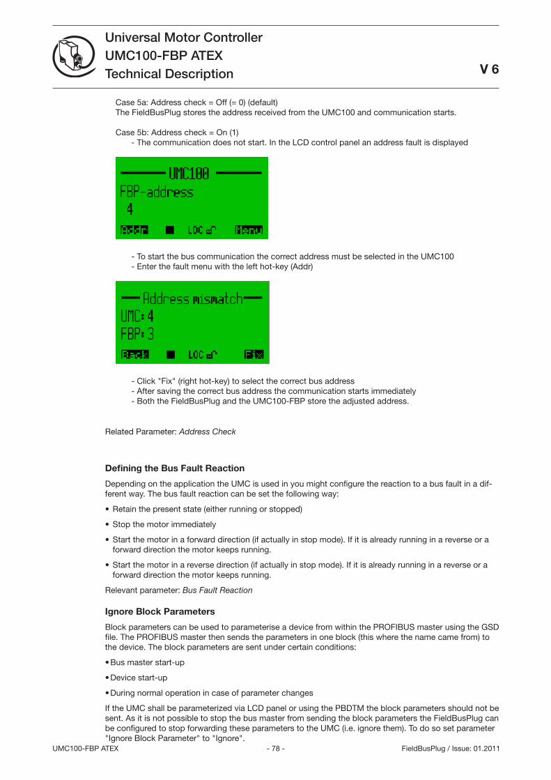
- 78 -UMC100-FBP ATEX
Universal Motor ControllerUMC100-FBP ATEXTechnical Description
V 6
FieldBusPlug / Issue: 01.2011
Case 5a: Address check = Off (= 0) (default) The FieldBusPlug stores the address received from the UMC100 and communication starts. Case 5b: Address check = On (1) - The communication does not start. In the LCD control panel an address fault is displayed
- To start the bus communication the correct address must be selected in the UMC100 - Enter the fault menu with the left hot-key (Addr)
- Click Fix (right hot-key) to select the correct bus address - After saving the correct bus address the communication starts immediately - Both the FieldBusPlug and the UMC100-FBP store the adjusted address.
Related Parameter: Address Check
Defining the Bus Fault Reaction
Depending on the application the UMC is used in you might configure the reaction to a bus fault in a dif-ferent way. The bus fault reaction can be set the following way:
Retain the present state (either running or stopped)
Stop the motor immediately
Start the motor in a forward direction (if actually in stop mode). If it is already running in a reverse or a forward direction the motor keeps running.
Start the motor in a reverse direction (if actually in stop mode). If it is already running in a reverse or a forward direction the motor keeps running.
Relevant parameter: Bus Fault Reaction
Ignore Block Parameters
Block parameters can be used to parameterise a device from within the PROFIBUS master using the GSD file. The PROFIBUS master then sends the parameters in one block (this where the name came from) to the device. The block parameters are sent under certain conditions:
Bus master start-up
Device start-up
During normal operation in case of parameter changes
If the UMC shall be parameterized via LCD panel or using the PBDTM the block parameters should not be sent. As it is not possible to stop the bus master from sending the block parameters the FieldBusPlug can be configured to stop forwarding these parameters to the UMC (i.e. ignore them). To do so set parameter Ignore Block Parameter to Ignore.
•
•
•
•
•
•
•
- 79 - UMC100-FBP ATEX
Universal Motor ControllerUMC100-FBP ATEXTechnical DescriptionV 6
FieldBusPlug / Issue: 01.2011
A typical customer error message if this parameter was not set is as follows: We set up everything correctly and the plant worked for weeks without problems. But then sud-denly the UMC lost its parameters."
What happened: The UMC was confi gured e.g. via LCD panel during commissioning. Then weeks later the bus master or controller was restarted for whatever reason and therefore sent the default UMC block parameters as they were never set.
If you are unsure if the parameter was set correctly you can also lock the parameters in the UMC. Then no parameter changes are possible anymore until the lock is reset. If
locked the small lock icon is set in the LCD display.
Relevant parameter:
Ignore Block Parameters.

- 80 -UMC100-FBP ATEX
Universal Motor ControllerUMC100-FBP ATEXTechnical Description
V 6
FieldBusPlug / Issue: 01.2011
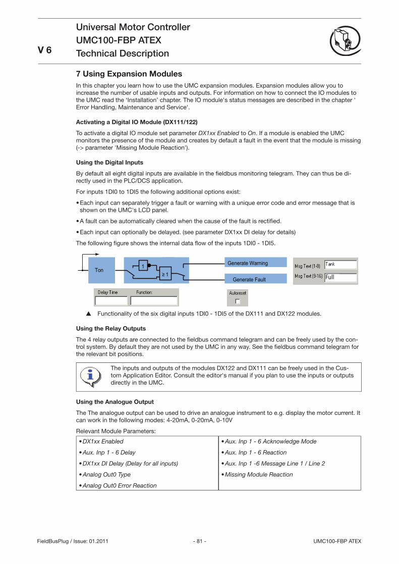
- 81 - UMC100-FBP ATEX
Universal Motor ControllerUMC100-FBP ATEXTechnical DescriptionV 6
FieldBusPlug / Issue: 01.2011
7 Using Expansion ModulesIn this chapter you learn how to use the UMC expansion modules. Expansion modules allow you to increase the number of usable inputs and outputs. For information on how to connect the IO modules to the UMC read the ‘Installation’ chapter. The IO module's status messages are described in the chapter ' Error Handling, Maintenance and Service'.
Activating a Digital IO Module ( DX111/ 122)
To activate a digital IO module set parameter DX1xx Enabled to On. If a module is enabled the UMC monitors the presence of the module and creates by default a fault in the event that the module is missing (-> parameter 'Missing Module Reaction').
Using the Digital Inputs
By default all eight digital inputs are available in the fi eldbus monitoring telegram. They can thus be di-rectly used in the PLC/DCS application.
For inputs 1DI0 to 1DI5 the following additional options exist:
Each input can separately trigger a fault or warning with a unique error code and error message that is shown on the UMC's LCD panel.
A fault can be automatically cleared when the cause of the fault is rectifi ed.
Each input can optionally be delayed. (see parameter DX1xx DI delay for details)
The following fi gure shows the internal data fl ow of the inputs 1DI0 - 1DI5.
Ton≥ 1
1
Generate Fault
Generate Warning
Full
Functionality of the six digital inputs 1DI0 - 1DI5 of the DX111 and DX122 modules.
Using the Relay Outputs
The 4 relay outputs are connected to the fi eldbus command telegram and can be freely used by the con-trol system. By default they are not used by the UMC in any way. See the fi eldbus command telegram for the relevant bit positions.
The inputs and outputs of the modules DX122 and DX111 can be freely used in the Cus-tom Application Editor. Consult the editor's manual if you plan to use the inputs or outputs directly in the UMC.
Using the Analogue Output
The The analogue output can be used to drive an analogue instrument to e.g. display the motor current. It can work in the following modes: 4-20mA, 0-20mA, 0-10V
Relevant Module Parameters:
DX1xx Enabled
Aux. Inp 1 - 6 Delay
DX1xx DI Delay (Delay for all inputs)
Analog Out0 Type
Analog Out0 Error Reaction
•
•
•
•
•
Aux. Inp 1 - 6 Acknowledge Mode
Aux. Inp 1 - 6 Reaction
Aux. Inp 1 -6 Message Line 1 / Line 2
Missing Module Reaction
•
•
•
•
•
•
•

- 82 -UMC100-FBP ATEX
Universal Motor ControllerUMC100-FBP ATEXTechnical Description
V 6
FieldBusPlug / Issue: 01.2011
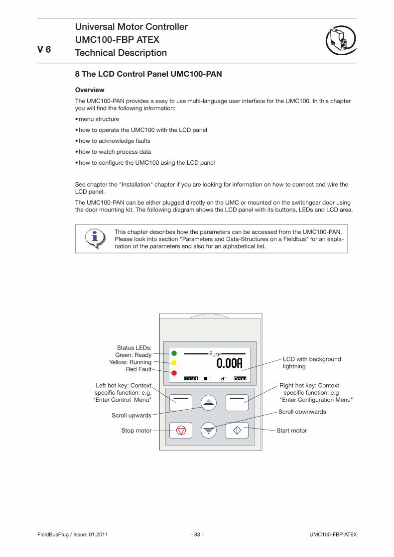
- 8 - UMC100-FBP ATEX
Universal Motor ControllerUMC100-FBP ATEXTechnical DescriptionV 6
FieldBusPlug / Issue: 01.2011
2CD
C
42 01
5F00
09
8 The LCD Control Panel UMC100-PAN
Overview
The UMC100-PAN provides a easy to use multi-language user interface for the UMC100. In this chapter you will fi nd the following information:
menu structure
how to operate the UMC100 with the LCD panel
how to acknowledge faults
how to watch process data
how to confi gure the UMC100 using the LCD panel
See chapter the Installation chapter if you are looking for information on how to connect and wire the LCD panel.
The UMC100-PAN can be either plugged directly on the UMC or mounted on the switchgear door using the door mounting kit. The following diagram shows the LCD panel with its buttons, LEDs and LCD area.
•
•
•
•
•
LCD with background lightning
Right hot key: Context - specifi c function: e.g Enter Confi guration Menu
Start motorStop motor
Left hot key: Context - specifi c function: e.g. Enter Control Menu
Status LEDs:Green: Ready
Yellow: RunningRed Fault
Scroll upwardsScroll downwards
This chapter describes how the parameters can be accessed from the UMC100-PAN. Please look into section Parameters and Data-Structures on a Fieldbus for an expla-nation of the parameters and also for an alphabetical list.
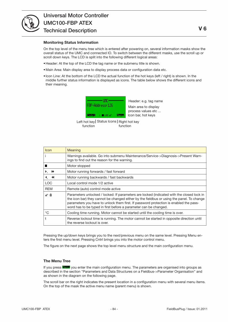
- 84 -UMC100-FBP ATEX
Universal Motor ControllerUMC100-FBP ATEXTechnical Description
V 6
FieldBusPlug / Issue: 01.2011
Icon Meaning
i Warnings available. Go into submenu Maintenance/Service->Diagnosis->Present Warn-ings to find out the reason for the warning.
Motor stopped
, Motor running forwards / fast forward
, Motor running backwards / fast backwards
LOC Local control mode 1/2 active
REM Remote (auto) control mode active
Parameters unlocked / locked: If parameters are locked (indicated with the closed lock in the icon bar) they cannot be changed either by the fieldbus or using the panel. To change parameters you have to unlock them first. If password protection is enabled the pass-word has to be typed in first before a parameter can be changed.
°C Cooling time running. Motor cannot be started until the cooling time is over.
t Reverse lockout time is running. The motor cannot be started in opposite direction until the reverse lockout is over.
Pressing the up/down keys brings you to the next/previous menu on the same level. Pressing Menu en-ters the first menu level. Pressing Cntrl brings you into the motor control menu.
The figure on the next page shows the top level menu structure and the main configuration menu.
The Menu Tree
If you press you enter the main configuration menu. The parameters are organised into groups as described in the section Parameters and Data Structures on a Fieldbus->Parameter Organisation and as shown in the diagram on the following page.
The scroll bar on the right indicates the present location in a configuration menu with several menu items. On the top of the mask the active menu name (parent menu) is shown.
Monitoring Status Information
On the top level of the menu tree which is entered after powering on, several information masks show the overall status of the UMC and connected IO. To switch between the different masks, use the scroll up or scroll down keys. The LCD is split into the following different logical areas:
Header: At the top of the LCD the tag name or the submenu title is shown.
Main Area: Main display area to display process data or configuration data etc.
Icon Line: At the bottom of the LCD the actual function of the hot keys (left / right) is shown. In the middle further status information is displayed as icons. The table below shows the different icons and their meaning.
•
•
•
Main area to display process values etc ...
Header: e.g. tag name
Status Icons Right hot key function
Left hot key function
Icon bar, hot keys
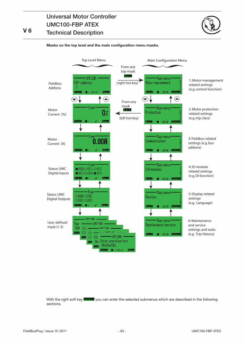
- 85 - UMC100-FBP ATEX
Universal Motor ControllerUMC100-FBP ATEXTechnical Description
V 6
FieldBusPlug / Issue: 01.2011
Masks on the top level and the main configuration menu masks.
FieldbusAddress
MotorCurrent [%]
MotorCurrent [A]
Status UMCDigital Inputs
Status UMCDigital Outputs
User-definedmask (1-5)
From anytop mask
(right hot key)
From anymask
(left hot key)
1: Motor managementrelated settings(e.g. control function)
2: Motor protectionrelated settings(e.g. trip class)
3: Fieldbus relatedsettings (e.g. busaddress)
4: IO modulerelated settings(e.g. DI function)
5: Display relatedsettings(e.g. Language)
6: Maintenanceand servicesettings and tasks(e.g. Trip History)
Top Level Menu Main Configuration Menu
With the right soft key you can enter the selected submenus which are described in the following sections.
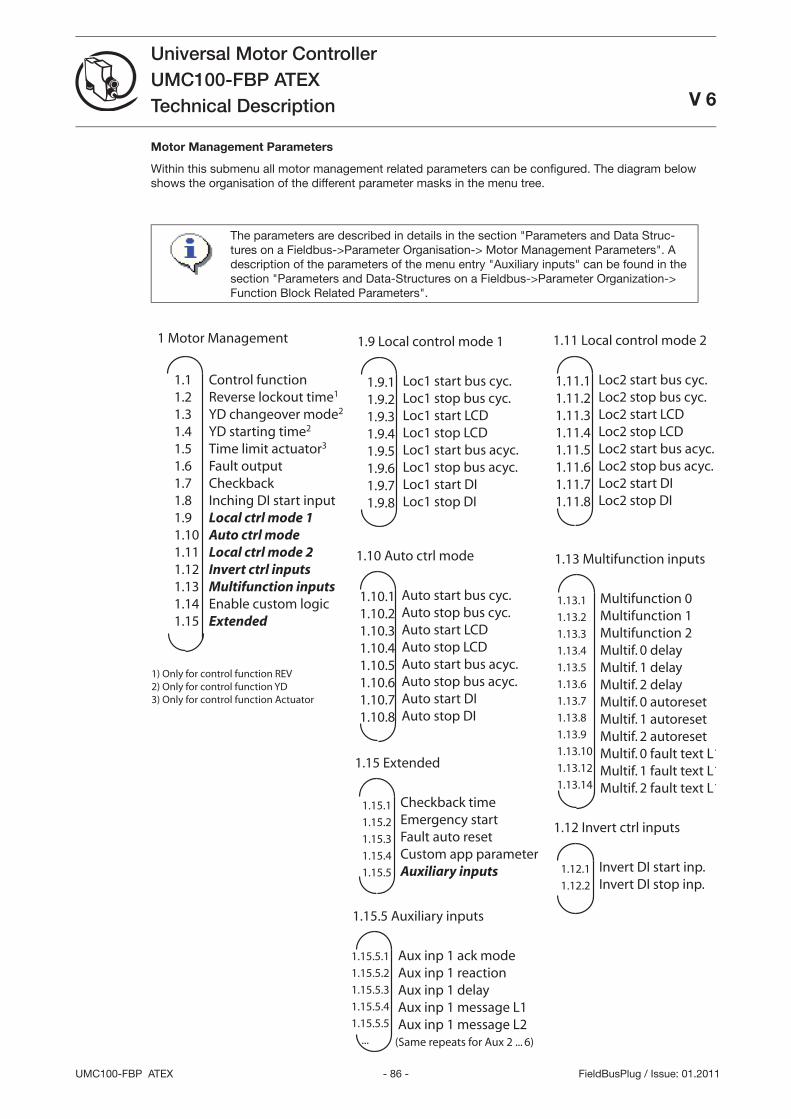
- 86 -UMC100-FBP ATEX
Universal Motor ControllerUMC100-FBP ATEXTechnical Description V 6
FieldBusPlug / Issue: 01.2011
Motor Management Parameters
Within this submenu all motor management related parameters can be confi gured. The diagram below shows the organisation of the different parameter masks in the menu tree.
Control functionReverse lockout time1
YD changeover mode2
YD starting time2
Time limit actuator3
Fault outputCheckbackInching DI start inputLocal ctrl mode 1Auto ctrl modeLocal ctrl mode 2Invert ctrl inputsMultifunction inputsEnable custom logicExtended
1 Motor Management
Loc1 start bus cyc.Loc1 stop bus cyc.Loc1 start LCDLoc1 stop LCDLoc1 start bus acyc.Loc1 stop bus acyc.Loc1 start DILoc1 stop DI
1.9 Local control mode 1
1.11.21.31.41.51.61.71.81.91.101.111.121.131.141.15
1.9.11.9.21.9.31.9.41.9.51.9.61.9.71.9.8
1) Only for control function REV2) Only for control function YD3) Only for control function Actuator
Loc2 start bus cyc.Loc2 stop bus cyc.Loc2 start LCDLoc2 stop LCDLoc2 start bus acyc.Loc2 stop bus acyc.Loc2 start DILoc2 stop DI
1.11 Local control mode 2
1.11.11.11.21.11.31.11.41.11.51.11.61.11.71.11.8
Auto start bus cyc.Auto stop bus cyc.Auto start LCDAuto stop LCDAuto start bus acyc.Auto stop bus acyc.Auto start DIAuto stop DI
1.10 Auto ctrl mode
1.10.11.10.21.10.31.10.41.10.51.10.61.10.71.10.8
Multifunction 0Multifunction 1Multifunction 2Multif. 0 delayMultif. 1 delayMultif. 2 delayMultif. 0 autoresetMultif. 1 autoresetMultif. 2 autoresetMultif. 0 fault text L1/2Multif. 1 fault text L1/2Multif. 2 fault text L1/2
1.13 Multifunction inputs
1.13.1
1.13.2
1.13.3
1.13.4
1.13.5
1.13.6
1.13.7
1.13.8
1.13.9
1.13.10
1.13.12
1.13.14
Checkback timeEmergency startFault auto resetCustom app parameterAuxiliary inputs
1.15 Extended
1.15.1
1.15.2
1.15.3
1.15.4
1.15.5 Invert DI start inp.Invert DI stop inp.
1.12 Invert ctrl inputs
1.12.1
1.12.2
Aux inp 1 ack modeAux inp 1 reactionAux inp 1 delayAux inp 1 message L1Aux inp 1 message L2
1.15.5 Auxiliary inputs
1.15.5.1
1.15.5.2
1.15.5.3
1.15.5.4
1.15.5.5
... (Same repeats for Aux 2 ... 6)
The parameters are described in details in the section Parameters and Data Struc-tures on a Fieldbus->Parameter Organisation-> Motor Management Parameters. A description of the parameters of the menu entry Auxiliary inputs can be found in the section Parameters and Data-Structures on a Fieldbus->Parameter Organization-> Function Block Related Parameters.
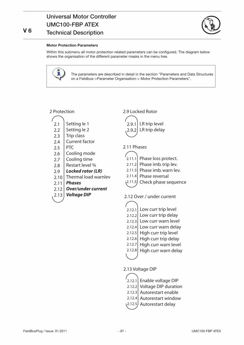
- 87 - UMC100-FBP ATEX
Universal Motor ControllerUMC100-FBP ATEXTechnical DescriptionV 6
FieldBusPlug / Issue: 01.2011
Motor Protection Parameters
Within this submenu all motor protection related parameters can be confi gured. The diagram below shows the organisation of the different parameter masks in the menu tree.
Setting Ie 1Setting Ie 2Trip classCurrent factorPTCCooling modeCooling timeRestart level %Locked rotor (LR)Thermal load warnlevPhasesOver/under currentVoltage DIP
2 Protection
2.12.22.32.42.52.62.72.82.92.102.112.122.13
Low curr trip levelLow curr trip delayLow curr warn levelLow curr warn delayHigh curr trip levelHigh curr trip delayHigh curr warn levelHigh curr warn delay
2.12 Over / under current
2.12.1
2.12.2
2.12.3
2.12.4
2.12.5
2.12.6
2.12.7
2.12.8
LR trip levelLR trip delay
2.9 Locked Rotor
2.9.12.9.2
Phase loss protect.Phase imb. trip lev.Phase imb. warn lev.Phase reversalCheck phase sequence
2.11 Phases
2.11.1
2.11.2
2.11.3
2.11.4
2.11.5
Enable voltage DIPVoltage DIP durationAutorestart enableAutorestart windowAutorestart delay
2.13 Voltage DIP
2.12.1
2.12.2
2.12.3
2.12.4
2.12.5
The parameters are described in detail in the section Parameters and Data Structures on a Fieldbus->Parameter Organisation-> Motor Protection Parameters.
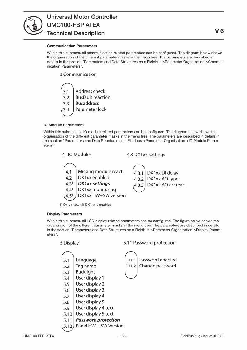
- 88 -UMC100-FBP ATEX
Universal Motor ControllerUMC100-FBP ATEXTechnical Description
V 6
FieldBusPlug / Issue: 01.2011
Communication Parameters
Within this submenu all communication related parameters can be configured. The diagram below shows the organisation of the different parameter masks in the menu tree. The parameters are described in details in the section Parameters and Data Structures on a Fieldbus->Parameter Organisation->Commu-nication Parameters.
Address checkBusfault reactionBusaddressParameter lock
3 Communication
3.13.23.33.4
IO Module Parameters
Within this submenu all IO module related parameters can be configured. The diagram below shows the organisation of the different parameter masks in the menu tree. The parameters are described in details in the section Parameters and Data Structures on a Fieldbus->Parameter Organisation->IO Module Param-eters.
Missing module react.DX1xx enabledDX1xx settingsDX1xx monitoringDX1xx HW+SW version
4 IO Modules
4.14.24.31
4.41
4.51
DX1xx DI delayDX1xx AO typeDX1xx AO err reac.
4.3.14.3.24.3.3
1) Only shown if DX1xx is enabled
4.3 DX1xx settings
Display Parameters
Within this submenu all LCD display related parameters can be configured. The figure below shows the organization of the different parameter masks in the menu tree. The parameters are described in details in the section Parameters and Data Structures on a Fieldbus->Parameter Organization->Display Param-eters.
LanguageTag nameBacklightUser display 1User display 2User display 3User display 4User display 5User display 4 textUser display 5 textPassword protectionPanel HW + SW Version
5 Display
5.15.25.35.45.55.65.75.85.95.105.115.12
Password enabledChange password
5.11 Password protection
5.11.1
5.11.2
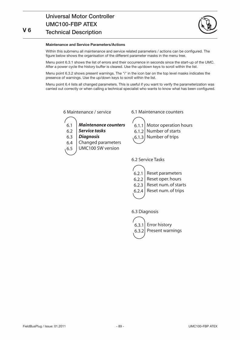
- 89 - UMC100-FBP ATEX
Universal Motor ControllerUMC100-FBP ATEXTechnical Description
V 6
FieldBusPlug / Issue: 01.2011
Maintenance and Service Parameters/Actions
Within this submenu all maintenance and service related parameters / actions can be configured. The figure below shows the organisation of the different parameter masks in the menu tree.
Menu point 6..1 shows the list of errors and their occurrence in seconds since the start-up of the UMC. After a power cycle the history buffer is cleared. Use the up/down keys to scroll within the list.
Menu point 6..2 shows present warnings. The i in the icon bar on the top level masks indicates the presence of warnings. Use the up/down keys to scroll within the list.
Menu point 6.4 lists all changed parameters. This is useful if you want to verify the parameterization was carried out correctly or when calling a technical specialist who wants to know what has been configured.
Maintenance countersService tasksDiagnosisChanged parametersUMC100 SW version
6 Maintenance / service
6.16.26.36.46.5
Motor operation hoursNumber of startsNumber of trips
6.1 Maintenance counters
6.1.16.1.26.1.3
Reset parametersReset oper. hoursReset num. of startsReset num. of trips
6.2 Service Tasks
6.2.16.2.26.2.36.2.4
Error historyPresent warnings
6.3 Diagnosis
6.3.16.3.2
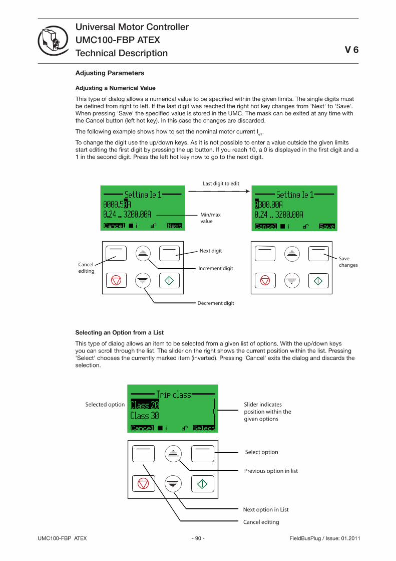
- 90 -UMC100-FBP ATEX
Universal Motor ControllerUMC100-FBP ATEXTechnical Description
V 6
FieldBusPlug / Issue: 01.2011
Adjusting Parameters
Adjusting a Numerical Value
This type of dialog allows a numerical value to be specified within the given limits. The single digits must be defined from right to left. If the last digit was reached the right hot key changes from 'Next' to 'Save'. When pressing 'Save' the specified value is stored in the UMC. The mask can be exited at any time with the Cancel button (left hot key). In this case the changes are discarded.
The following example shows how to set the nominal motor current Ie1.
To change the digit use the up/down keys. As it is not possible to enter a value outside the given limits start editing the first digit by pressing the up button. If you reach 10, a 0 is displayed in the first digit and a 1 in the second digit. Press the left hot key now to go to the next digit.
Savechanges
Increment digit
Decrement digit
Cancel editing
Min/maxvalue
Last digit to edit
Next digit
Selecting an Option from a List
This type of dialog allows an item to be selected from a given list of options. With the up/down keys you can scroll through the list. The slider on the right shows the current position within the list. Pressing 'Select' chooses the currently marked item (inverted). Pressing 'Cancel' exits the dialog and discards the selection.
Select option
Previous option in list
Next option in List
Cancel editing
Slider indicatesposition within thegiven options
Selected option
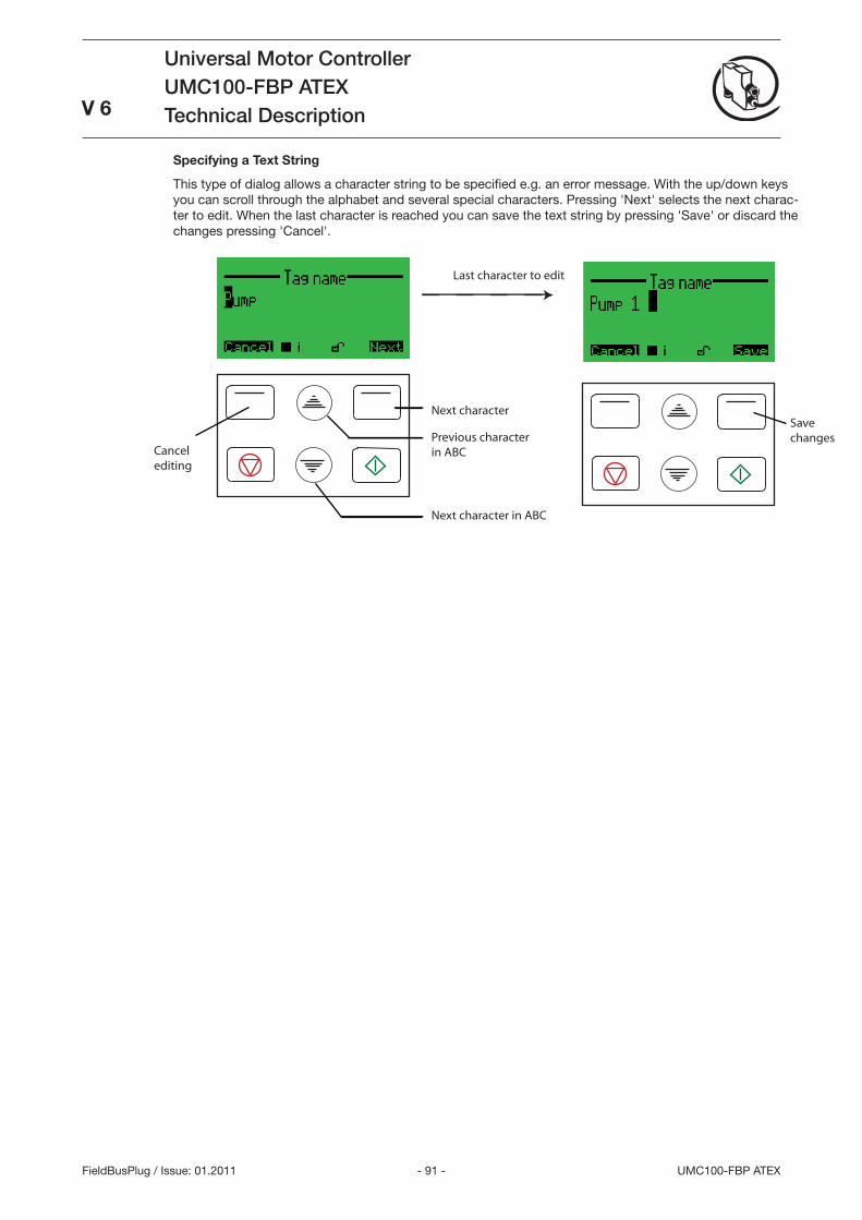
- 91 - UMC100-FBP ATEX
Universal Motor ControllerUMC100-FBP ATEXTechnical Description
V 6
FieldBusPlug / Issue: 01.2011
Next character
Previous character in ABC
Next character in ABC
Cancel editing
Last character to edit
Savechanges
Specifying a Text String
This type of dialog allows a character string to be specified e.g. an error message. With the up/down keys you can scroll through the alphabet and several special characters. Pressing 'Next' selects the next charac-ter to edit. When the last character is reached you can save the text string by pressing 'Save' or discard the changes pressing 'Cancel'.
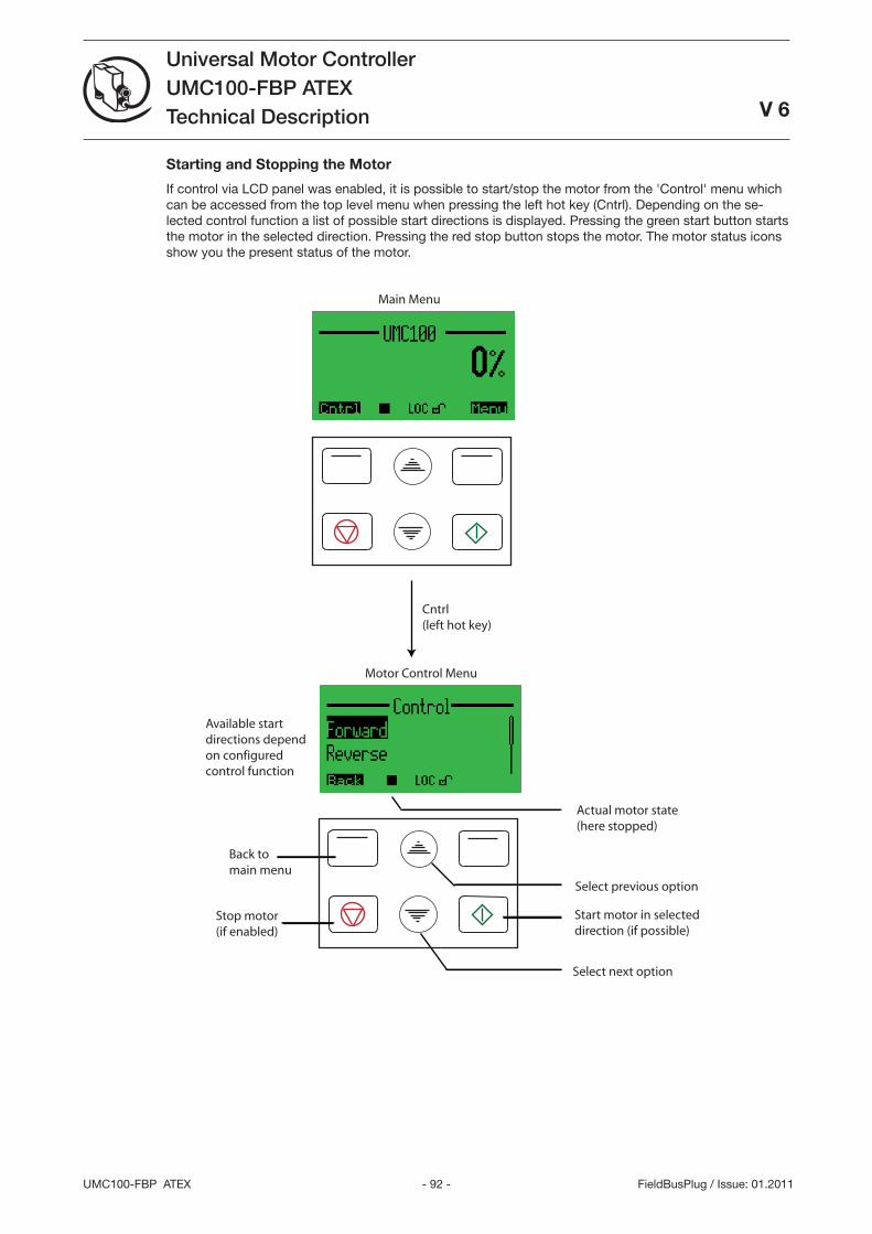
- 92 -UMC100-FBP ATEX
Universal Motor ControllerUMC100-FBP ATEXTechnical Description
V 6
FieldBusPlug / Issue: 01.2011
Starting and Stopping the Motor
If control via LCD panel was enabled, it is possible to start/stop the motor from the 'Control' menu which can be accessed from the top level menu when pressing the left hot key (Cntrl). Depending on the se-lected control function a list of possible start directions is displayed. Pressing the green start button starts the motor in the selected direction. Pressing the red stop button stops the motor. The motor status icons show you the present status of the motor.
Select previous option
Select next option
Back to main menu
Available startdirections dependon configuredcontrol function
Start motor in selecteddirection (if possible)
Stop motor (if enabled)
Actual motor state(here stopped)
Cntrl(left hot key)
Main Menu
Motor Control Menu
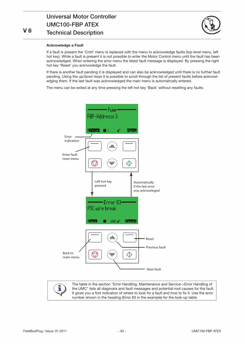
- 9 - UMC100-FBP ATEX
Universal Motor ControllerUMC100-FBP ATEXTechnical DescriptionV 6
FieldBusPlug / Issue: 01.2011
Acknowledge a Fault
If a fault is present the 'Cntrl' menu is replaced with the menu to acknowledge faults (top level menu, left hot key). While a fault is present it is not possible to enter the Motor Control menu until the fault has been acknowledged. When entering the error menu the latest fault message is displayed. By pressing the right hot key ‘Reset’ you acknowledge the fault.
If there is another fault pending it is displayed and can also be acknowledged until there is no further fault pending. Using the up/down keys it is possible to scroll through the list of present faults before acknowl-edging them. If the last fault was acknowledged the main menu is automatically entered.
The menu can be exited at any time pressing the left hot key ‘Back’ without resetting any faults.
Enter fault reset menu
Error indication
Left hot keypressed
Back tomain menu
Reset
Automaticallyif the last errorwas acknowleged
Previous fault
Next fault
The table in the section Error Handling, Maintenance and Service->Error Handling of the UMC lists all diagnosis and fault messages and potential root causes for the fault. It gives you a fi rst indication of where to look for a fault and how to fi x it. Use the error number shown in the heading (Error 8 in the example) for the look-up table.
- 94 -UMC100-FBP ATEX
Universal Motor ControllerUMC100-FBP ATEXTechnical Description
V 6
FieldBusPlug / Issue: 01.2011
- 95 - UMC100-FBP ATEX
Universal Motor ControllerUMC100-FBP ATEXTechnical Description
V 6
FieldBusPlug / Issue: 01.2011
9 Error Handling, Maintenance and ServiceWithin this chapter you will find the following information
Error handling of the UMC
Detailed explanation of all error and diagnosis messages
Functions related to maintenance and service
Error Handling of the UMC
When the UMC detects a fault condition the fault becomes latched. Once a fault becomes latched, it remains latched - even if the underlying fault condition is eliminated - until acknowledged by a fault reset command.
Automatic Reset of Protection Faults
The setting of the Fault autoreset parameter determines how the UMC manages protection trips.
Off (the default setting): A protection trip must be acknowledged by the user. This can be done via LCD panel, fieldbus or the multifunction inputs DI0-DI2 if configured.
On: A protection trip is automatically acknowledged without intervention of either a human operator or
the remote PLC if the trip condition has gone (e.g. cooling time over).
Fault History
The DTM provides access to the fault history. The last 16 faults and their arrival time in seconds since power on are displayed. If the UMC is switched off the fault history is cleared.
UMC100 Fault Indication
The UMC offers the following possibilities for indicating a fault.
Fault indication via digital outputs: The outputs DO2 and DO can be used to signal a summary fault. DO2 is a relay output that uses the same supply as DO0 and DO1. DO is a 24VDC output and can be used to drive a signal lamp as an example. The fault outputs can be configured with the parameter Fault Outputs.
Fault indication via LEDs on the UMC: The red fault LED is switched on in the event of a fault and re-mains on until the fault is acknowledged.
Fault messages on the LCD panel: See the table below.
Signalling via fieldbus: In the event of a fault the Fault Bit in the cyclic communication telegram is set to logical-1. Furthermore a diagnosis telegram (if supported by the used fieldbus) is generated that describes the fault details.
Fault Messages
The following table lists all diagnosis and fault messages and potential root causes for the fault. It gives you a first indication of where to look for a fault and how to fix it.
Indicator Code Source / Root Cause Possible Cause / Suggested Action
Thermal overload trip 0 Load side Trip because of thermal overload of the motor.
Check process conditions Check if the cooling time is too short Check Ie and trip class settings Check current factor if configured
•
•
•
•
•
•
•
•
•
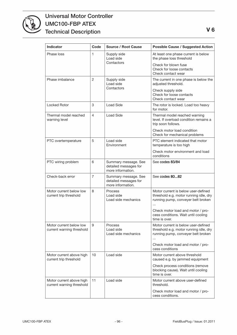
- 96 -UMC100-FBP ATEX
Universal Motor ControllerUMC100-FBP ATEXTechnical Description
V 6
FieldBusPlug / Issue: 01.2011
Indicator Code Source / Root Cause Possible Cause / Suggested Action
Phase loss 1 Supply side Load side Contactors
At least one phase current is below the phase loss threshold
Check for blown fuse Check for loose contacts Check contact wear
Phase imbalance 2 Supply side Load side Contactors
The current in one phase is below the adjusted threshold.
Check supply side Check for loose contacts Check contact wear
Locked Rotor Load Side The rotor is locked. Load too heavy for motor.
Thermal model reached warning level
4 Load Side Thermal model reached warning level. If overload condition remains a trip soon follows.
Check motor load condition Check for mechanical problems
PTC overtemperature 5 Load side Environment
PTC element indicated that motor temperature is too high
Check motor environment and load conditions
PTC wiring problem 6 Summary message. See detailed messages for more information.
See codes 8/84codes 8/84 8/84
Check-back error 7 Summary message. See detailed messages for more information.
See codes 80...82codes 80...82 80...82
Motor current below low current trip threshold
8 Process Load side Load side mechanics
Motor current is below user-defined threshold e.g. motor running idle, dry running pump, conveyer belt broken ...
Check motor load and motor / pro-cess conditions. Wait until cooling time is over.
Motor current below low current warning threshold
9 Process Load side Load side mechanics
Motor current is below user-defined threshold e.g. motor running idle, dry running pump, conveyer belt broken ...
Check motor load and motor / pro-cess conditions
Motor current above high current trip threshold
10 Load side Motor current above threshold caused e.g. by jammed equipment
Check process conditions (remove blocking cause). Wait until cooling time is over.
Motor current above high current warning threshold
11 Load side Motor current above user-defined threshold.
Check motor load and motor / pro-cess conditions.
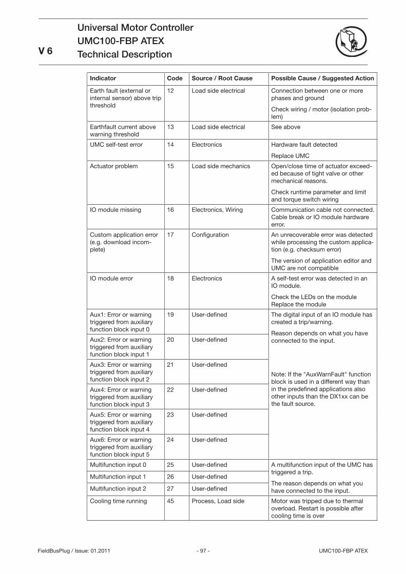
- 97 - UMC100-FBP ATEX
Universal Motor ControllerUMC100-FBP ATEXTechnical Description
V 6
FieldBusPlug / Issue: 01.2011
Indicator Code Source / Root Cause Possible Cause / Suggested Action
Earth fault (external or internal sensor) above trip threshold
12 Load side electrical Connection between one or more phases and ground
Check wiring / motor (isolation prob-lem)
Earthfault current above warning threshold
1 Load side electrical See above
UMC self-test error 14 Electronics Hardware fault detected
Replace UMC
Actuator problem 15 Load side mechanics Open/close time of actuator exceed-ed because of tight valve or other mechanical reasons.
Check runtime parameter and limit and torque switch wiring
IO module missing 16 Electronics, Wiring Communication cable not connected. Cable break or IO module hardware error.
Custom application error (e.g. download incom-plete)
17 Configuration An unrecoverable error was detected while processing the custom applica-tion (e.g. checksum error)
The version of application editor and UMC are not compatible
IO module error 18 Electronics A self-test error was detected in an IO module.
Check the LEDs on the module Replace the module
Aux1: Error or warning triggered from auxiliary function block input 0
19 User-defined The digital input of an IO module has created a trip/warning.
Reason depends on what you have connected to the input.
Note: If the AuxWarnFault function block is used in a different way than in the predefined applications also other inputs than the DX1xx can be the fault source.
Aux2: Error or warning triggered from auxiliary function block input 1
20 User-defined
Aux: Error or warning triggered from auxiliary function block input 2
21 User-defined
Aux4: Error or warning triggered from auxiliary function block input
22 User-defined
Aux5: Error or warning triggered from auxiliary function block input 4
2 User-defined
Aux6: Error or warning triggered from auxiliary function block input 5
24 User-defined
Multifunction input 0 25 User-defined A multifunction input of the UMC has triggered a trip.
The reason depends on what you have connected to the input.
Multifunction input 1 26 User-defined
Multifunction input 2 27 User-defined
Cooling time running 45 Process, Load side Motor was tripped due to thermal overload. Restart is possible after cooling time is over
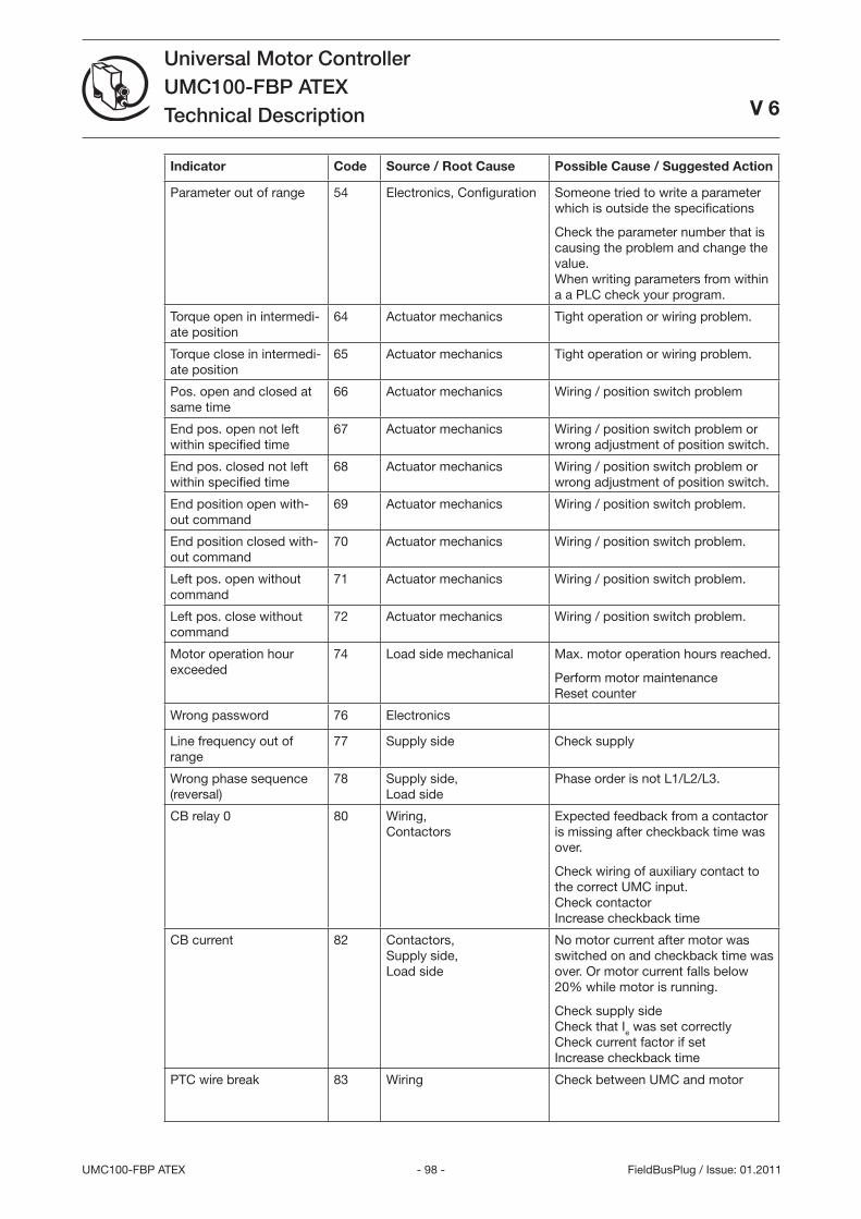
- 98 -UMC100-FBP ATEX
Universal Motor ControllerUMC100-FBP ATEXTechnical Description
V 6
FieldBusPlug / Issue: 01.2011
Indicator Code Source / Root Cause Possible Cause / Suggested Action
Parameter out of range 54 Electronics, Configuration Someone tried to write a parameter which is outside the specifications
Check the parameter number that is causing the problem and change the value. When writing parameters from within a a PLC check your program.
Torque open in intermedi-ate position
64 Actuator mechanics Tight operation or wiring problem.
Torque close in intermedi-ate position
65 Actuator mechanics Tight operation or wiring problem.
Pos. open and closed at same time
66 Actuator mechanics Wiring / position switch problem
End pos. open not left within specified time
67 Actuator mechanics Wiring / position switch problem or wrong adjustment of position switch.
End pos. closed not left within specified time
68 Actuator mechanics Wiring / position switch problem or wrong adjustment of position switch.
End position open with-out command
69 Actuator mechanics Wiring / position switch problem.
End position closed with-out command
70 Actuator mechanics Wiring / position switch problem.
Left pos. open without command
71 Actuator mechanics Wiring / position switch problem.
Left pos. close without command
72 Actuator mechanics Wiring / position switch problem.
Motor operation hour exceeded
74 Load side mechanical Max. motor operation hours reached.
Perform motor maintenance Reset counter
Wrong password 76 Electronics
Line frequency out of range
77 Supply side Check supply
Wrong phase sequence (reversal)
78 Supply side, Load side
Phase order is not L1/L2/L.
CB relay 0 80 Wiring, Contactors
Expected feedback from a contactor is missing after checkback time was over.
Check wiring of auxiliary contact to the correct UMC input. Check contactor Increase checkback time
CB current 82 Contactors, Supply side, Load side
No motor current after motor was switched on and checkback time was over. Or motor current falls below 20% while motor is running.
Check supply side Check that Ie was set correctly Check current factor if set Increase checkback time
PTC wire break 8 Wiring Check between UMC and motor
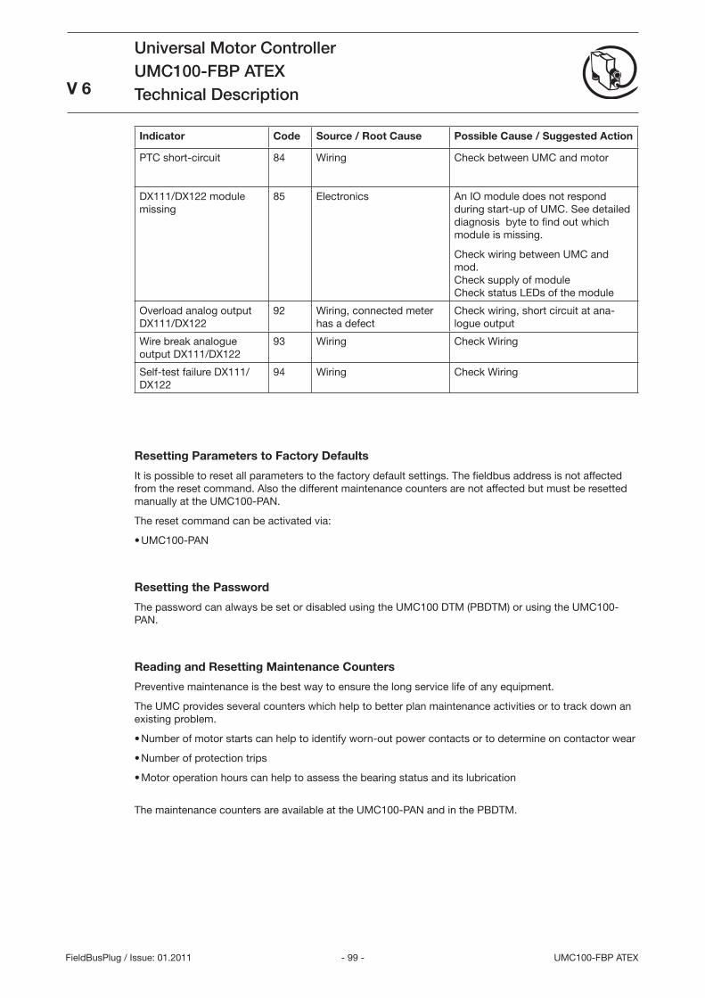
- 99 - UMC100-FBP ATEX
Universal Motor ControllerUMC100-FBP ATEXTechnical Description
V 6
FieldBusPlug / Issue: 01.2011
Indicator Code Source / Root Cause Possible Cause / Suggested Action
PTC short-circuit 84 Wiring Check between UMC and motor
DX111/DX122 module missing
85 Electronics An IO module does not respond during start-up of UMC. See detailed diagnosis byte to find out which module is missing.
Check wiring between UMC and mod. Check supply of module Check status LEDs of the module
Overload analog output DX111/DX122
92 Wiring, connected meter has a defect
Check wiring, short circuit at ana-logue output
Wire break analogue output DX111/DX122
9 Wiring Check Wiring
Self-test failure DX111/DX122
94 Wiring Check Wiring
Resetting Parameters to Factory Defaults
It is possible to reset all parameters to the factory default settings. The fieldbus address is not affected from the reset command. Also the different maintenance counters are not affected but must be resetted manually at the UMC100-PAN.
The reset command can be activated via:
UMC100-PAN
Resetting the Password
The password can always be set or disabled using the UMC100 DTM (PBDTM) or using the UMC100-PAN.
Reading and Resetting Maintenance Counters
Preventive maintenance is the best way to ensure the long service life of any equipment.
The UMC provides several counters which help to better plan maintenance activities or to track down an existing problem.
Number of motor starts can help to identify worn-out power contacts or to determine on contactor wear
Number of protection trips
Motor operation hours can help to assess the bearing status and its lubrication
The maintenance counters are available at the UMC100-PAN and in the PBDTM.
•
•
•
•
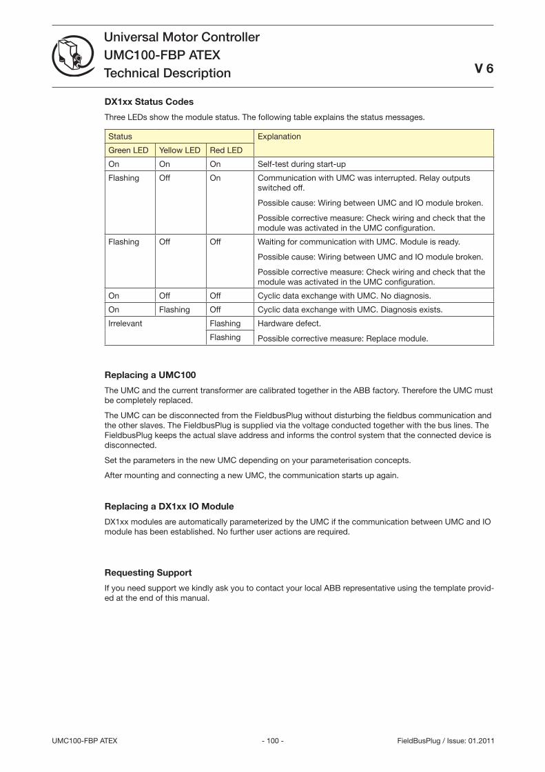
- 100 -UMC100-FBP ATEX
Universal Motor ControllerUMC100-FBP ATEXTechnical Description
V 6
FieldBusPlug / Issue: 01.2011
DX1xx Status Codes
Three LEDs show the module status. The following table explains the status messages.
Status Explanation
Green LED Yellow LED Red LED
On On On Self-test during start-up
Flashing Off On Communication with UMC was interrupted. Relay outputs switched off.
Possible cause: Wiring between UMC and IO module broken.
Possible corrective measure: Check wiring and check that the module was activated in the UMC configuration.
Flashing Off Off Waiting for communication with UMC. Module is ready.
Possible cause: Wiring between UMC and IO module broken.
Possible corrective measure: Check wiring and check that the module was activated in the UMC configuration.
On Off Off Cyclic data exchange with UMC. No diagnosis.
On Flashing Off Cyclic data exchange with UMC. Diagnosis exists.
Irrelevant Flashing Hardware defect.
Possible corrective measure: Replace module.Flashing
Replacing a UMC100
The UMC and the current transformer are calibrated together in the ABB factory. Therefore the UMC must be completely replaced.
The UMC can be disconnected from the FieldbusPlug without disturbing the fieldbus communication and the other slaves. The FieldbusPlug is supplied via the voltage conducted together with the bus lines. The FieldbusPlug keeps the actual slave address and informs the control system that the connected device is disconnected.
Set the parameters in the new UMC depending on your parameterisation concepts.
After mounting and connecting a new UMC, the communication starts up again.
Replacing a DX1xx IO Module
DX1xx modules are automatically parameterized by the UMC if the communication between UMC and IO module has been established. No further user actions are required.
Requesting Support
If you need support we kindly ask you to contact your local ABB representative using the template provid-ed at the end of this manual.
- 101 - UMC100-FBP ATEX
Universal Motor ControllerUMC100-FBP ATEXTechnical Description
FieldBusPlug / Issue: 11.2009
V 6
10 Safety and Commissioning Notes for Motors in EEx Areas
Introduction
This chapter provides safety and commissioning notes for motors that are installed in explosive atmospheres. The UMC100 is a 1-channel device providing internal self tests which guarantees reliable motor protection on a high level. A suitable housing for the UMC is required when using the UMC in EX areas.
The output side of the UMC100 must not be connected to frequency converters or similar components.
The UMC100 is approved for device group II, category 2 zones G or D (i.e., explosive atmospheres caused by gases, vapors, mists or air, or by combustible dust).
It is essential to observe the following notes! All work required for connection, commissioning and maintenance must be performed by qualifi ed personnel. Improper behavior may cause serious injury to persons or material damages.
The UMC100 was developed and designed according to the standards IEC 61508 and ISO1849.
The increased risks in EEx areas require, amongst other things, careful observation of the following notes and standards:
IEC 60079-7: Electrical apparatus for explosive atmospheres
IEC 60079-14/17: Electrical apparatus for explosive atmospheres
IEC 61241-14: Electrical apparatus for use in the presence of combustible dust - Selection and erection
IEC 61241-17: Electrical apparatus for use in the presence of combustible dust - Inspection and maintenance of electrical installations in hazardous areas
Safe state
For the reverse starter control function, the safe state is present if the relays DO0 and DO1 are de-energized (open).
For all other motor operation modes (e. g. DOL, Star-Delta Start), the safe state is present if relay DO0 is de-energized (open).
Safety functions
The following functions of the UMC100 are safety-relevant:
Thermal overload protection: The thermal overload protection function induces the de-energization of the relay(s) if the device detects a thermal overload situation (calculated using the thermal model) or a phase loss.
Thermistor motor protection: This safety function brings the system to the safe state if the resistance measured at the PTC inputs (T1/T2) exceeds the limit specifi ed in the corresponding standard. This safety function only has to be activated if the motor provides a corresponding sensor.
•
•
•
•
•
•
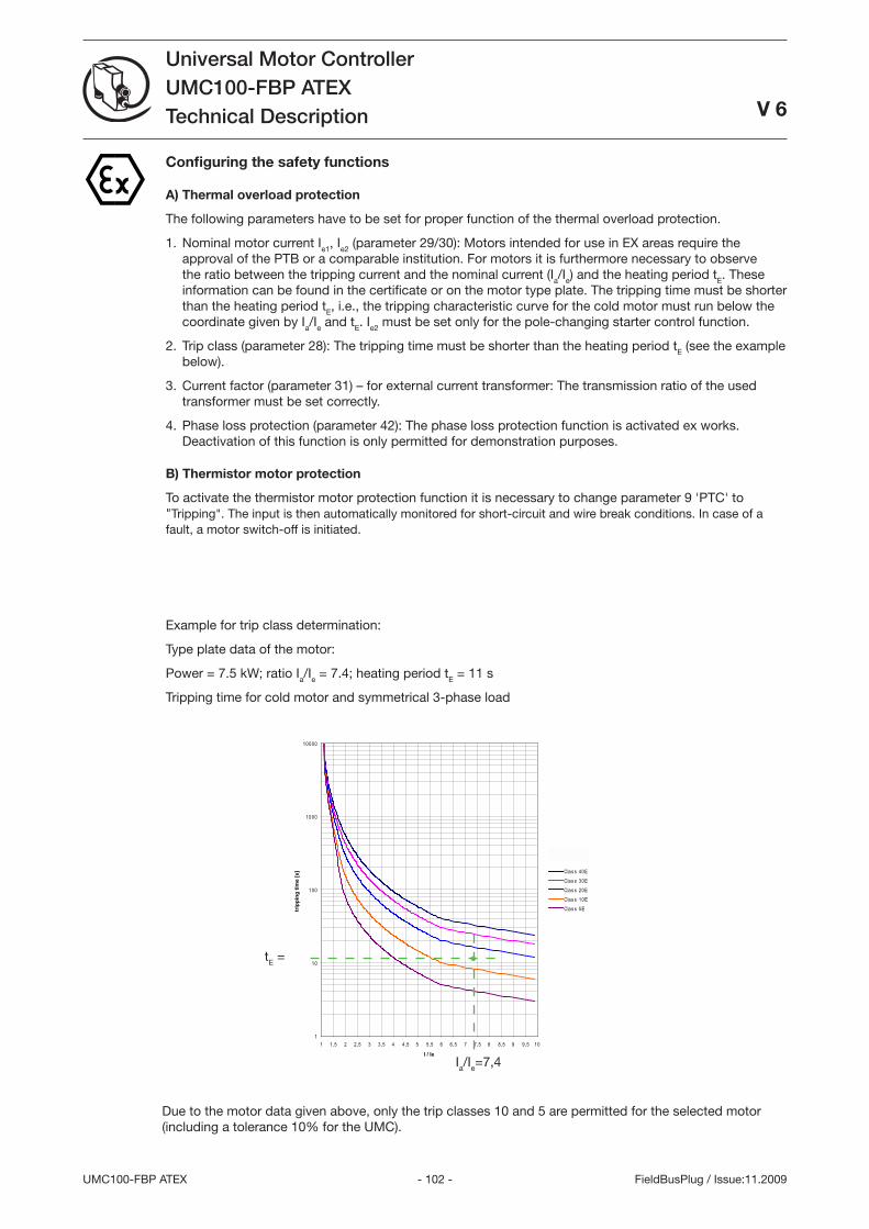
- 102 -UMC100-FBP ATEX
Universal Motor ControllerUMC100-FBP ATEXTechnical Description
FieldBusPlug / Issue:11.2009
V 6
1
10
100
1000
10000
1 1,5 2 2,5 3 3,5 4 4,5 5 5,5 6 6,5 7 7,5 8 8,5 9 9,5 10
I / Ie
trip
ping
tim
e [s
] Clas s 40EClas s 30EClas s 20EClas s 10EClas s 5E
Configuring the safety functions
A) Thermal overload protection
The following parameters have to be set for proper function of the thermal overload protection.
Nominal motor current Ie1, Ie2 (parameter 29/0): Motors intended for use in EX areas require the approval of the PTB or a comparable institution. For motors it is furthermore necessary to observe the ratio between the tripping current and the nominal current (Ia/Ie) and the heating period tE. These information can be found in the certificate or on the motor type plate. The tripping time must be shorter than the heating period tE, i.e., the tripping characteristic curve for the cold motor must run below the coordinate given by Ia/Ie and tE. Ie2 must be set only for the pole-changing starter control function.
Trip class (parameter 28): The tripping time must be shorter than the heating period tE (see the example below).
Current factor (parameter 1) – for external current transformer: The transmission ratio of the used transformer must be set correctly.
Phase loss protection (parameter 42): The phase loss protection function is activated ex works. Deactivation of this function is only permitted for demonstration purposes.
B) Thermistor motor protection
To activate the thermistor motor protection function it is necessary to change parameter 9 'PTC' to Tripping. The input is then automatically monitored for short-circuit and wire break conditions. In case of a fault, a motor switch-off is initiated.
1.
2.
.
4.
Example for trip class determination:
Type plate data of the motor:
Power = 7.5 kW; ratio Ia/Ie = 7.4; heating period tE = 11 s
Tripping time for cold motor and symmetrical -phase load
Due to the motor data given above, only the trip classes 10 and 5 are permitted for the selected motor (including a tolerance 10% for the UMC).
Ia/Ie=7,4
tE =
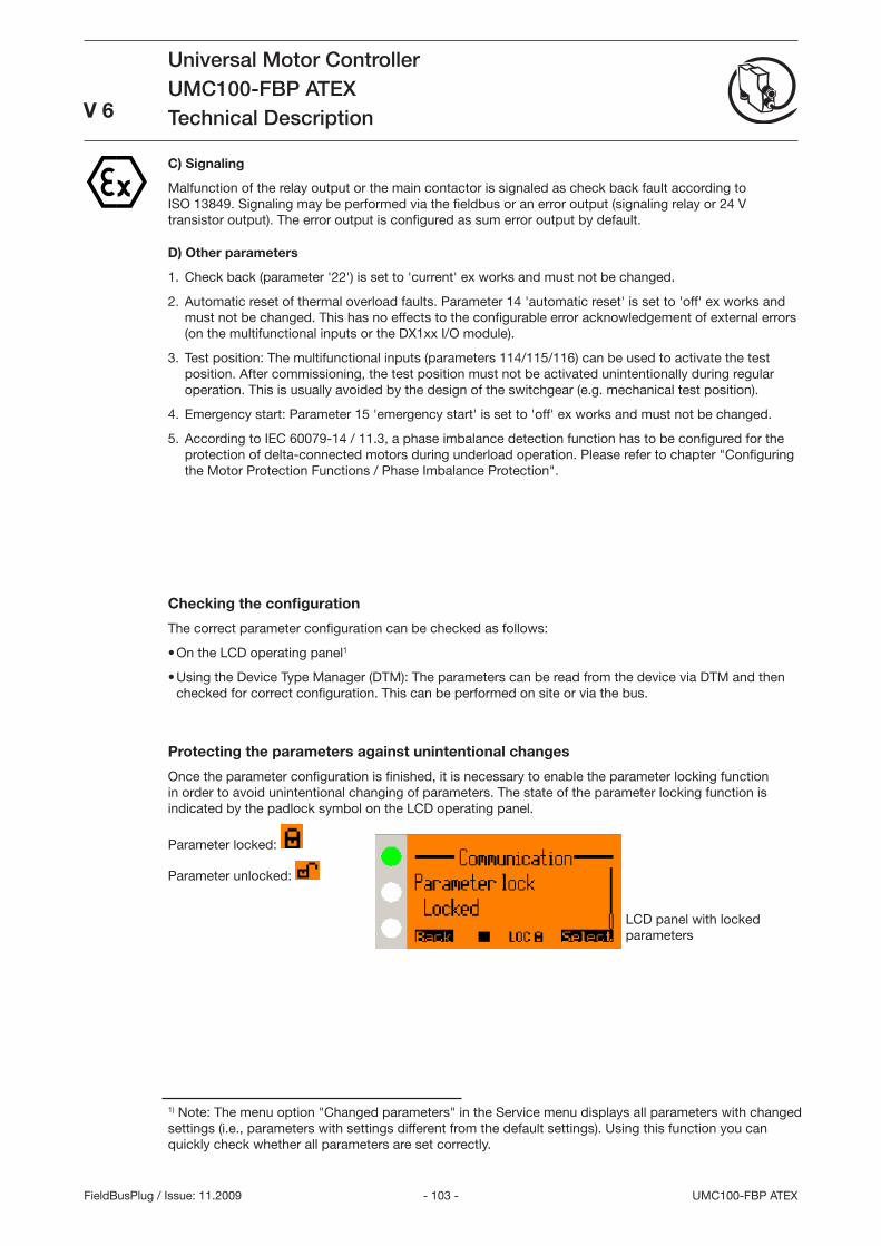
- 10 - UMC100-FBP ATEX
Universal Motor ControllerUMC100-FBP ATEXTechnical Description
FieldBusPlug / Issue: 11.2009
V 6
C) Signaling
Malfunction of the relay output or the main contactor is signaled as check back fault according to ISO 1849. Signaling may be performed via the fieldbus or an error output (signaling relay or 24 V transistor output). The error output is configured as sum error output by default.
D) Other parameters
Check back (parameter '22') is set to 'current' ex works and must not be changed.
Automatic reset of thermal overload faults. Parameter 14 'automatic reset' is set to 'off' ex works and must not be changed. This has no effects to the configurable error acknowledgement of external errors (on the multifunctional inputs or the DX1xx I/O module).
Test position: The multifunctional inputs (parameters 114/115/116) can be used to activate the test position. After commissioning, the test position must not be activated unintentionally during regular operation. This is usually avoided by the design of the switchgear (e.g. mechanical test position).
Emergency start: Parameter 15 'emergency start' is set to 'off' ex works and must not be changed.
According to IEC 60079-14 / 11., a phase imbalance detection function has to be configured for the protection of delta-connected motors during underload operation. Please refer to chapter Configuring the Motor Protection Functions / Phase Imbalance Protection.
1.
2.
.
4.
5.
Checking the configuration
The correct parameter configuration can be checked as follows:
On the LCD operating panel1
Using the Device Type Manager (DTM): The parameters can be read from the device via DTM and then checked for correct configuration. This can be performed on site or via the bus.
Protecting the parameters against unintentional changes
Once the parameter configuration is finished, it is necessary to enable the parameter locking function in order to avoid unintentional changing of parameters. The state of the parameter locking function is indicated by the padlock symbol on the LCD operating panel.
Parameter locked:
Parameter unlocked:
•
•
LCD panel with locked parameters
1) Note: The menu option Changed parameters in the Service menu displays all parameters with changed settings (i.e., parameters with settings different from the default settings). Using this function you can quickly check whether all parameters are set correctly.
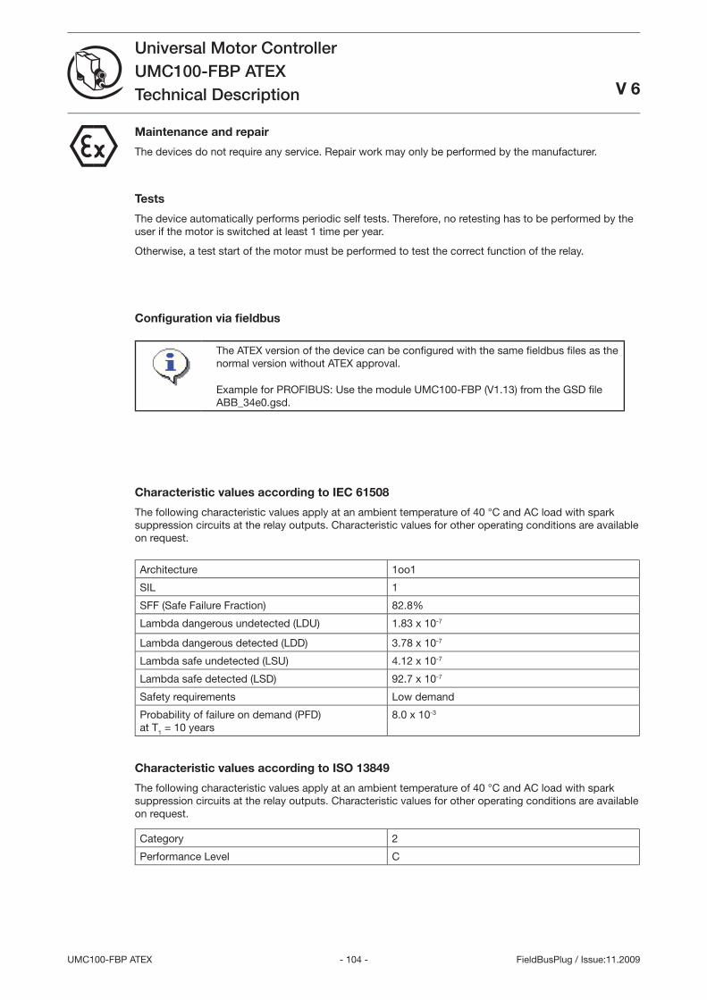
- 104 -UMC100-FBP ATEX
Universal Motor ControllerUMC100-FBP ATEXTechnical Description
FieldBusPlug / Issue:11.2009
V 6
Maintenance and repair
The devices do not require any service. Repair work may only be performed by the manufacturer.
Tests
The device automatically performs periodic self tests. Therefore, no retesting has to be performed by the user if the motor is switched at least 1 time per year.
Otherwise, a test start of the motor must be performed to test the correct function of the relay.
Confi guration via fi eldbus
The ATEX version of the device can be confi gured with the same fi eldbus fi les as the normal version without ATEX approval.
Example for PROFIBUS: Use the module UMC100-FBP (V1.1) from the GSD fi le ABB_4e0.gsd.
Characteristic values according to IEC 61508
The following characteristic values apply at an ambient temperature of 40 °C and AC load with spark suppression circuits at the relay outputs. Characteristic values for other operating conditions are available on request.
Architecture 1oo1
SIL 1
SFF (Safe Failure Fraction) 82.8%
Lambda dangerous undetected (LDU) 1.8 x 10⁻⁷
Lambda dangerous detected (LDD) .78 x 10-7
Lambda safe undetected (LSU) 4.12 x 10⁻⁷
Lambda safe detected (LSD) 92.7 x 10⁻⁷
Safety requirements Low demand
Probability of failure on demand (PFD)at T1 = 10 years
8.0 x 10-
Characteristic values according to ISO 13849
The following characteristic values apply at an ambient temperature of 40 °C and AC load with spark suppression circuits at the relay outputs. Characteristic values for other operating conditions are available on request.
Category 2
Performance Level C
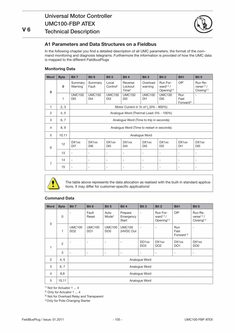
- 105 - UMC100-FBP ATEX
Universal Motor ControllerUMC100-FBP ATEXTechnical DescriptionV 6
FieldBusPlug / Issue: 01.2011
A1 Parameters and Data Structures on a FieldbusIn the following chapter you fi nd a detailed description of all UMC parameters, the format of the com-mand monitoring and diagnosis telegrams. Furthermore the information is provided of how the UMC data is mapped to the different FieldbusPlugs
Monitoring Data
Word Byte Bit 7 Bit 6 Bit 5 Bit 4 Bit 3 Bit 2 Bit1 Bit 0
0
0Summary Warning
Summary Fault
Local Control
Reverse Lockout Time
Overload warning
Run For-ward1, / Opening2,
Off Run Re-verse1, / Closing2,
1UMC100 DI5
UMC100 DI4
UMC100 DI
UMC100 DI2
UMC100 DI1
UMC100 DI0
Run Fast Forward4)
-
1 2, Motor Current in % of Ie (0% - 800%)
2 4, 5 Analogue Word (Thermal Load: 0% - 100%)
6, 7 Analogue Word (Time to trip in seconds)
4 8, 9 Analogue Word (Time to restart in seconds)
5 10.11 Analogue Word
612
DX1xx DI7
DX1xxDI6
DX1xxDI5
DX1xxDI4
DX1xxDI
DX1xxDI2
DX1xxDI1
DX1xxDI0
1 - - - - - - - -
714 - - - - - - - -
15 - - - - - - - -
The table above represents the data allocation as realised with the built-in standard applica-tions. It may differ for customer-specifi c applications!
Command Data
Word Byte Bit 7 Bit 6 Bit 5 Bit 4 Bit 3 Bit 2 Bit1 Bit 0
0
0- Fault
ResetAuto Mode
Prepare Emergency Start
- Run For-ward1. / Opening2,
Off Run Re-verse1, / Closing2,
1UMC100 DO2
UMC100 DO1
UMC100 DO0
UMC100 24VDC Out
- - Run Fast Forward 4)
-
12
- - - - DO1xxDO
DX1xxDO2
DX1xxDO1
DX1xxDO0
- - - - - - - -
2 4, 5 Analogue Word
6, 7 Analogue Word
4 8,9 Analogue Word
5 10,11 Analogue Word
1) Not for Actuator 1 ... 4 2) Only for Actuator 1 ... 4 ) Not for Overload Relay and Transparent4) Only for Pole-Changing Starter
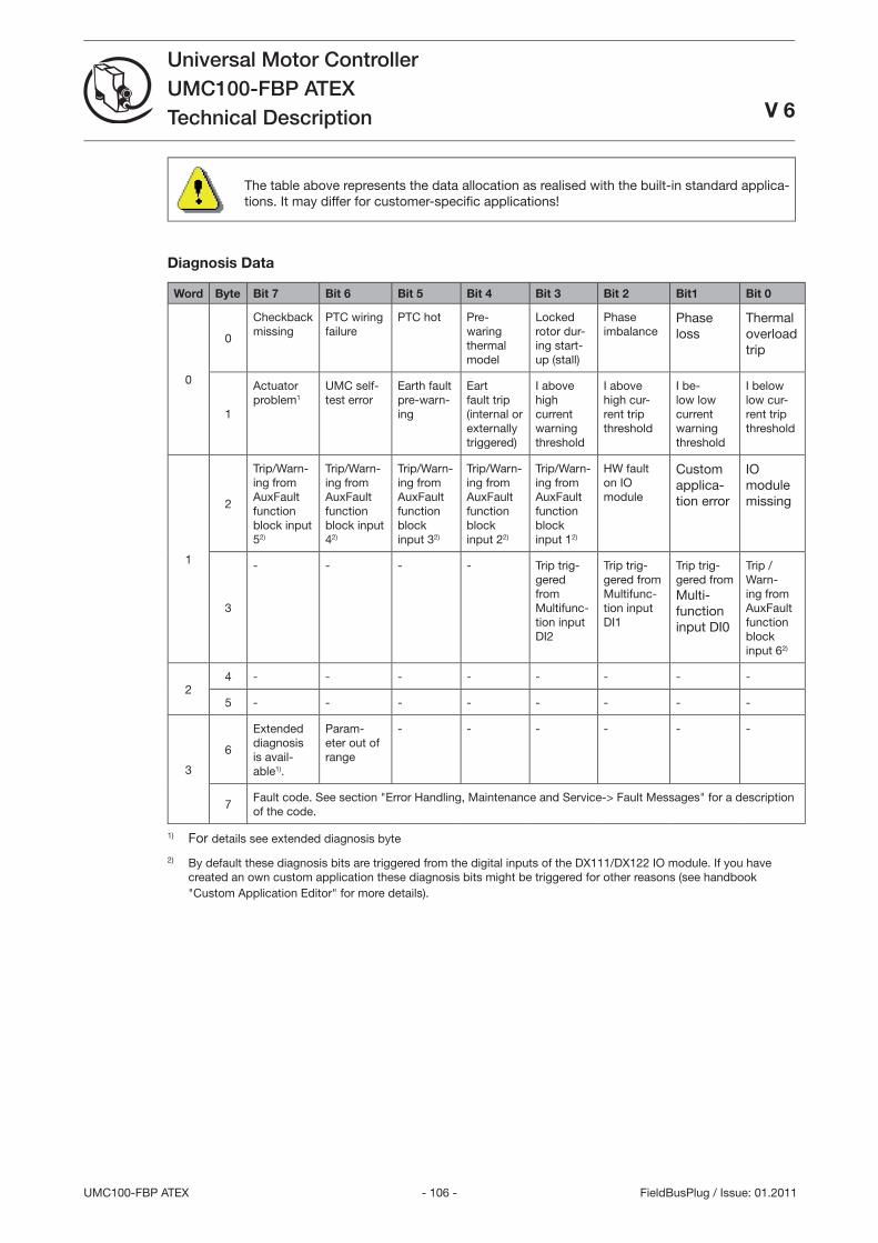
- 106 -UMC100-FBP ATEX
Universal Motor ControllerUMC100-FBP ATEXTechnical Description V 6
FieldBusPlug / Issue: 01.2011
The table above represents the data allocation as realised with the built-in standard applica-tions. It may differ for customer-specifi c applications!
Diagnosis Data
Word Byte Bit 7 Bit 6 Bit 5 Bit 4 Bit 3 Bit 2 Bit1 Bit 0
0
0
Checkback missing
PTC wiring failure
PTC hot Pre-waring thermal model
Locked rotor dur-ing start-up (stall)
Phase imbalance
Phase loss
Thermal overload trip
1
Actuator problem1
UMC self-test error
Earth fault pre-warn-ing
Eart fault trip (internal or externally triggered)
I above high current warning threshold
I above high cur-rent trip threshold
I be-low low current warning threshold
I below low cur-rent trip threshold
1
2
Trip/Warn-ing from AuxFault function block input 52)
Trip/Warn-ing from AuxFault function block input 42)
Trip/Warn-ing from AuxFault function block input 2)
Trip/Warn-ing from AuxFault function block input 22)
Trip/Warn-ing from AuxFault function block input 12)
HW fault on IO module
Custom applica-tion error
IO module missing
- - - - Trip trig-gered from Multifunc-tion input DI2
Trip trig-gered from Multifunc-tion input DI1
Trip trig-gered from Multi-function input DI0
Trip / Warn-ing from AuxFault function block input 62)
24 - - - - - - - -
5 - - - - - - - -
6
Extended diagnosis is avail-able1).
Param-eter out of range
- - - - - -
7Fault code. See section Error Handling, Maintenance and Service-> Fault Messages for a description of the code.
1) For details see extended diagnosis byte
2) By default these diagnosis bits are triggered from the digital inputs of the DX111/DX122 IO module. If you have created an own custom application these diagnosis bits might be triggered for other reasons (see handbook Custom Application Editor for more details).
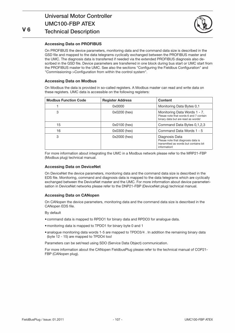
- 107 - UMC100-FBP ATEX
Universal Motor ControllerUMC100-FBP ATEXTechnical Description
V 6
FieldBusPlug / Issue: 01.2011
Accessing Data on PROFIBUS
On PROFIBUS the device parameters, monitoring data and the command data size is described in the GSD file and mapped to the data telegrams cyclically exchanged between the PROFIBUS master and the UMC. The diagnosis data is transferred if needed via the extended PROFIBUS diagnosis also de-scribed in the GSD file. Device parameters are transferred in one block during bus start or UMC start from the PROFIBUS master to the UMC. See also the sections Configuring the Fieldbus Configuration and Commissioning->Configuration from within the control system.
Accessing Data on Modbus
On Modbus the data is provided in so-called registers. A Modbus master can read and write data on these registers. UMC data is accessible on the following registers:
Modbus Function Code Register Address Content
1 0x0000 Monitoring Data Bytes 0,1
0x0200 (hex) Monitoring Data Words 1 - 7. Plesae note that words 6 and 7 contain binary data but are read as words!
15 0x0100 (hex) Command Data Bytes 0,1,2,
16 0x000 (hex) Command Data Words 1 - 5
0x2000 (hex) Diagnosis Data Plesae note that diagnosis data is transmitted as words but contains bit information!
For more information about integrating the UMC in a Modbus network please refer to the MRP21-FBP (Modbus plug) technical manual.
Accessing Data on DeviceNet
On DeviceNet the device parameters, monitoring data and the command data size is described in the EDS file. Monitoring, command and diagnosis data is mapped to the data telegrams which are cyclically exchanged between the DeviceNet master and the UMC. For more information about device parameteri-sation in DeviceNet networks please refer to the DNP21-FBP (DeviceNet plug) technical manual.
Accessing Data on CANopen
On CANopen the device parameters, monitoring data and the command data size is described in the CANopen EDS file.
By default
command data is mapped to RPDO1 for binary data and RPDO for analogue data.
monitoring data is mapped to TPDO1 for binary byte 0 and 1
analogue monitoring data words 1-5 are mapped to TPDO/4 . In addition the remaining binary data (byte 12 - 15) are mapped to TPDO4 too!
Parameters can be set/read using SDO (Service Data Object) communication.
For more information about the CANopen FieldbusPlug please refer to the technical manual of COP21-FBP (CANopen plug).
•
•
•
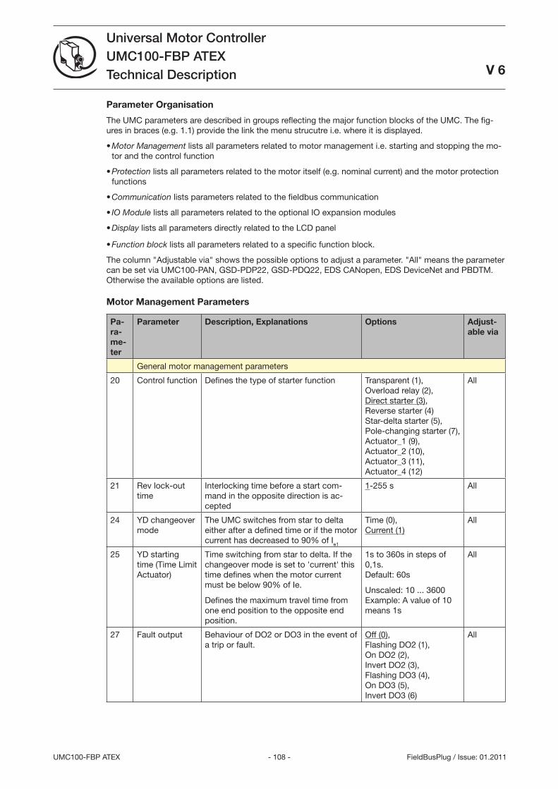
- 108 -UMC100-FBP ATEX
Universal Motor ControllerUMC100-FBP ATEXTechnical Description
V 6
FieldBusPlug / Issue: 01.2011
Parameter Organisation
The UMC parameters are described in groups reflecting the major function blocks of the UMC. The fig-ures in braces (e.g. 1.1) provide the link the menu strucutre i.e. where it is displayed.
Motor Management lists all parameters related to motor management i.e. starting and stopping the mo-tor and the control function
Protection lists all parameters related to the motor itself (e.g. nominal current) and the motor protection functions
Communication lists parameters related to the fieldbus communication
IO Module lists all parameters related to the optional IO expansion modules
Display lists all parameters directly related to the LCD panel
Function block lists all parameters related to a specific function block.
The column Adjustable via shows the possible options to adjust a parameter. All means the parameter can be set via UMC100-PAN, GSD-PDP22, GSD-PDQ22, EDS CANopen, EDS DeviceNet and PBDTM. Otherwise the available options are listed.
Motor Management Parameters
Pa-ra-me-ter
Parameter Description, Explanations Options Adjust-able via
General motor management parameters
20 Control function Defines the type of starter function Transparent (1), Overload relay (2), Direct starter (), Reverse starter (4) Star-delta starter (5), Pole-changing starter (7), Actuator_1 (9), Actuator_2 (10), Actuator_ (11), Actuator_4 (12)
All
21 Rev lock-out time
Interlocking time before a start com-mand in the opposite direction is ac-cepted
1-255 s All
24 YD changeover mode
The UMC switches from star to delta either after a defined time or if the motor current has decreased to 90% of Ie1
Time (0), Current (1)
All
25 YD starting time (Time Limit Actuator)
Time switching from star to delta. If the changeover mode is set to 'current' this time defines when the motor current must be below 90% of Ie.
Defines the maximum travel time from one end position to the opposite end position.
1s to 60s in steps of 0,1s. Default: 60s
Unscaled: 10 ... 600 Example: A value of 10 means 1s
All
27 Fault output Behaviour of DO2 or DO in the event of a trip or fault.
Off (0), Flashing DO2 (1), On DO2 (2), Invert DO2 (), Flashing DO (4), On DO (5), Invert DO (6)
All
•
•
•
•
•
•
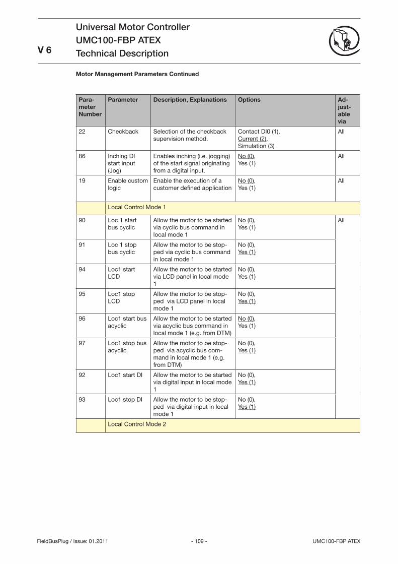
- 109 - UMC100-FBP ATEX
Universal Motor ControllerUMC100-FBP ATEXTechnical Description
V 6
FieldBusPlug / Issue: 01.2011
Para-meter Number
Parameter Description, Explanations Options Ad-just-able via
22 Checkback Selection of the checkback supervision method.
Contact DI0 (1), Current (2), Simulation ()
All
86 Inching DI start input (Jog)
Enables inching (i.e. jogging) of the start signal originating from a digital input.
No (0), Yes (1)
All
19 Enable custom logic
Enable the execution of a customer defined application
No (0), Yes (1)
All
Local Control Mode 1
90 Loc 1 start bus cyclic
Allow the motor to be started via cyclic bus command in local mode 1
No (0), Yes (1)
All
91 Loc 1 stop bus cyclic
Allow the motor to be stop-ped via cyclic bus command in local mode 1
No (0), Yes (1)
94 Loc1 start LCD
Allow the motor to be started via LCD panel in local mode 1
No (0), Yes (1)
95 Loc1 stop LCD
Allow the motor to be stop-ped via LCD panel in local mode 1
No (0), Yes (1)
96 Loc1 start bus acyclic
Allow the motor to be started via acyclic bus command in local mode 1 (e.g. from DTM)
No (0), Yes (1)
97 Loc1 stop bus acyclic
Allow the motor to be stop-ped via acyclic bus com-mand in local mode 1 (e.g. from DTM)
No (0), Yes (1)
92 Loc1 start DI Allow the motor to be started via digital input in local mode 1
No (0), Yes (1)
9 Loc1 stop DI Allow the motor to be stop-ped via digital input in local mode 1
No (0), Yes (1)
Local Control Mode 2
Motor Management Parameters Continued
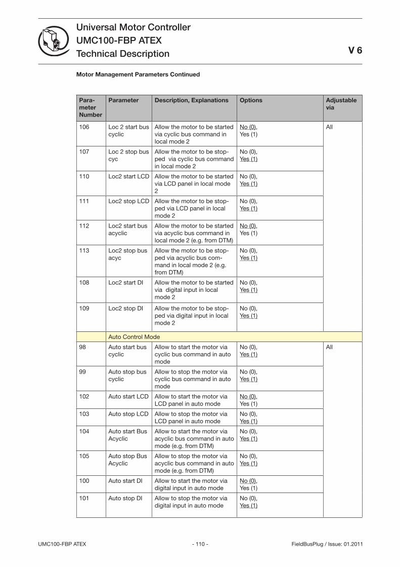
- 110 -UMC100-FBP ATEX
Universal Motor ControllerUMC100-FBP ATEXTechnical Description
V 6
FieldBusPlug / Issue: 01.2011
Para-meter Number
Parameter Description, Explanations Options Adjustable via
106 Loc 2 start bus cyclic
Allow the motor to be started via cyclic bus command in local mode 2
No (0), Yes (1)
All
107 Loc 2 stop bus cyc
Allow the motor to be stop-ped via cyclic bus command in local mode 2
No (0), Yes (1)
110 Loc2 start LCD Allow the motor to be started via LCD panel in local mode 2
No (0), Yes (1)
111 Loc2 stop LCD Allow the motor to be stop-ped via LCD panel in local mode 2
No (0), Yes (1)
112 Loc2 start bus acyclic
Allow the motor to be started via acyclic bus command in local mode 2 (e.g. from DTM)
No (0), Yes (1)
11 Loc2 stop bus acyc
Allow the motor to be stop-ped via acyclic bus com-mand in local mode 2 (e.g. from DTM)
No (0), Yes (1)
108 Loc2 start DI Allow the motor to be started via digital input in local mode 2
No (0), Yes (1)
109 Loc2 stop DI Allow the motor to be stop-ped via digital input in local mode 2
No (0), Yes (1)
Auto Control Mode
98 Auto start bus cyclic
Allow to start the motor via cyclic bus command in auto mode
No (0), Yes (1)
All
99 Auto stop bus cyclic
Allow to stop the motor via cyclic bus command in auto mode
No (0), Yes (1)
102 Auto start LCD Allow to start the motor via LCD panel in auto mode
No (0), Yes (1)
10 Auto stop LCD Allow to stop the motor via LCD panel in auto mode
No (0), Yes (1)
104 Auto start Bus Acyclic
Allow to start the motor via acyclic bus command in auto mode (e.g. from DTM)
No (0), Yes (1)
105 Auto stop Bus Acyclic
Allow to stop the motor via acyclic bus command in auto mode (e.g. from DTM)
No (0), Yes (1)
100 Auto start DI Allow to start the motor via digital input in auto mode
No (0), Yes (1)
101 Auto stop DI Allow to stop the motor via digital input in auto mode
No (0), Yes (1)
Motor Management Parameters Continued
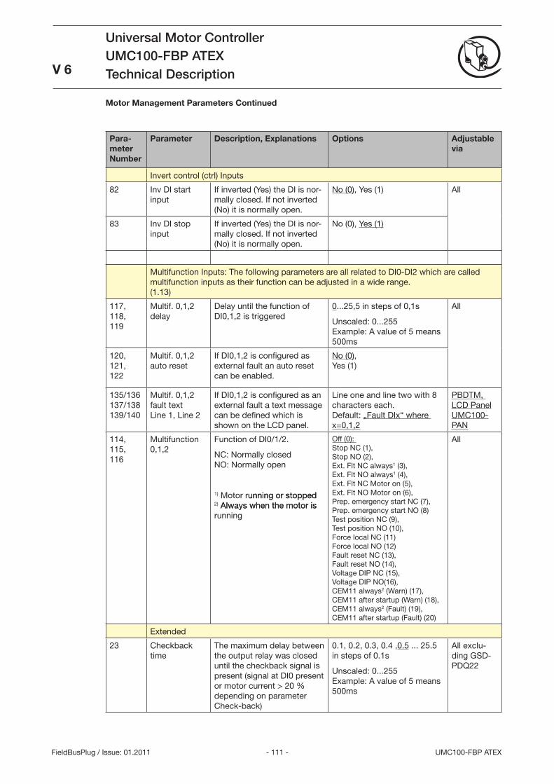
- 111 - UMC100-FBP ATEX
Universal Motor ControllerUMC100-FBP ATEXTechnical Description
V 6
FieldBusPlug / Issue: 01.2011
Para-meter Number
Parameter Description, Explanations Options Adjustable via
Invert control (ctrl) Inputs
82 Inv DI start input
If inverted (Yes) the DI is nor-mally closed. If not inverted (No) it is normally open.
No (0), Yes (1) All
8 Inv DI stop input
If inverted (Yes) the DI is nor-mally closed. If not inverted (No) it is normally open.
No (0), Yes (1)
Multifunction Inputs: The following parameters are all related to DI0-DI2 which are called multifunction inputs as their function can be adjusted in a wide range. (1.1)
117, 118, 119
Multif. 0,1,2 delay
Delay until the function of DI0,1,2 is triggered
0...25,5 in steps of 0,1s
Unscaled: 0...255 Example: A value of 5 means 500ms
All
120, 121, 122
Multif. 0,1,2 auto reset
If DI0,1,2 is configured as external fault an auto reset can be enabled.
No (0), Yes (1)
15/16 17/18 19/140
Multif. 0,1,2 fault text Line 1, Line 2
If DI0,1,2 is configured as an external fault a text message can be defined which is shown on the LCD panel.
Line one and line two with 8 characters each. Default: „Fault DIx“ where x=0,1,2
PBDTM, LCD Panel UMC100-PAN
114, 115, 116
Multifunction 0,1,2
Function of DI0/1/2.
NC: Normally closed NO: Normally open
1) Motor running or stoppedunning or stopped 2) Always when the motor isAlways when the motor is running
Off (0): Stop NC (1), Stop NO (2), Ext. Flt NC always1 (), Ext. Flt NO always1 (4), Ext. Flt NC Motor on (5), Ext. Flt NO Motor on (6), Prep. emergency start NC (7), Prep. emergency start NO (8) Test position NC (9), Test position NO (10), Force local NC (11) Force local NO (12) Fault reset NC (1), Fault reset NO (14), Voltage DIP NC (15), Voltage DIP NO(16), CEM11 always2 (Warn) (17), CEM11 after startup (Warn) (18), CEM11 always2 (Fault) (19), CEM11 after startup (Fault) (20)
All
Extended
2 Checkback time
The maximum delay between the output relay was closed until the checkback signal is present (signal at DI0 present or motor current > 20 % depending on parameter Check-back)
0.1, 0.2, 0., 0.4 ,0.5 ... 25.5 in steps of 0.1s
Unscaled: 0...255 Example: A value of 5 means 500ms
All exclu-ding GSD-PDQ22
Motor Management Parameters Continued
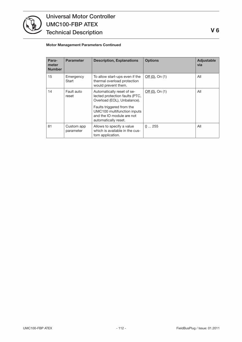
- 112 -UMC100-FBP ATEX
Universal Motor ControllerUMC100-FBP ATEXTechnical Description
V 6
FieldBusPlug / Issue: 01.2011
Motor Management Parameters Continued
Para-meter Number
Parameter Description, Explanations Options Adjustable via
15 Emergency Start
To allow start-ups even if the thermal overload protection would prevent them.
Off (0), On (1) All
14 Fault auto reset
Automatically reset of se-lected protection faults (PTC, Overload (EOL), Unbalance).
Faults triggered from the UMC100 multifunction inputs and the IO module are not automatically reset.
Off (0), On (1) All
81 Custom app parameter
Allows to specify a value which is available in the cus-tom application.
0 ... 255 All
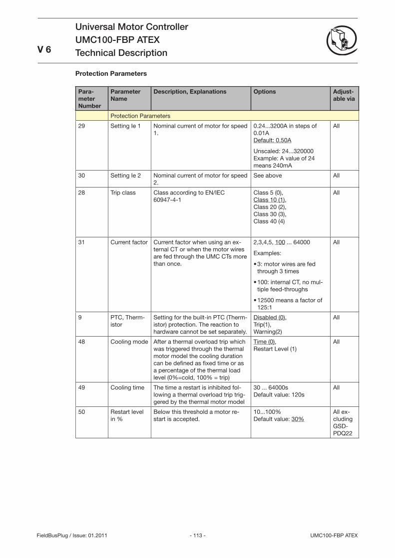
- 11 - UMC100-FBP ATEX
Universal Motor ControllerUMC100-FBP ATEXTechnical Description
V 6
FieldBusPlug / Issue: 01.2011
Protection Parameters
Para-meter Number
Parameter Name
Description, Explanations Options Adjust-able via
Protection Parameters
29 Setting Ie 1 Nominal current of motor for speed 1.
0.24...200A in steps of 0.01A Default: 0.50A
Unscaled: 24...20000 Example: A value of 24 means 240mA
All
0 Setting Ie 2 Nominal current of motor for speed 2.
See above All
28 Trip class Class according to EN/IEC 60947-4-1
Class 5 (0), Class 10 (1), Class 20 (2), Class 0 (), Class 40 (4)
All
1 Current factor Current factor when using an ex-ternal CT or when the motor wires are fed through the UMC CTs more than once.
2,,4,5, 100 ... 64000
Examples:
: motor wires are fed through times
100: internal CT, no mul-tiple feed-throughs
12500 means a factor of 125:1
•
•
•
All
9 PTC, Therm-istor
Setting for the built-in PTC (Therm-istor) protection. The reaction to hardware cannot be set separately.
Disabled (0), Trip(1), Warning(2)
All
48 Cooling mode After a thermal overload trip which was triggered through the thermal motor model the cooling duration can be defined as fixed time or as a percentage of the thermal load level (0%=cold, 100% = trip)
Time (0), Restart Level (1)
All
49 Cooling time The time a restart is inhibited fol-lowing a thermal overload trip trig-gered by the thermal motor model
0 ... 64000s Default value: 120s
All
50 Restart level in %
Below this threshold a motor re-start is accepted.
10...100% Default value: 0%
All ex-cluding GSD-PDQ22
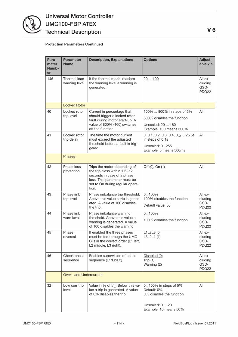
- 114 -UMC100-FBP ATEX
Universal Motor ControllerUMC100-FBP ATEXTechnical Description
V 6
FieldBusPlug / Issue: 01.2011
Para-meter Numb-er
Parameter Name
Description, Explanations Options Adjust-able via
146 Thermal load warning level
If the thermal model reaches the warning level a warning is generated.
20 ... 100 All ex-cluding GSD-PDQ22
Locked Rotor
40 Locked rotor trip level
Current in percentage that should trigger a locked rotor fault during motor start-up. A value of 800% (160) switches off the function.
100% ... 800% in steps of 5%
800% disables the function
Unscaled: 20 ... 160 Example: 100 means 500%
All
41 Locked rotor trip delay
The time the motor current must exceed the adjusted threshold before a fault is trig-gered.
0, 0.1, 0.2, 0., 0.4, 0.5 ... 25.5s in steps of 0.1s
Unscaled: 0...255 Example: 5 means 500ms
All
Phases
42 Phase loss protection
Trips the motor depending of the trip class within 1.5 -12 seconds in case of a phase loss. This parameter must be set to On during regular opera-tion.
Off (0), On (1) All
4 Phase imb trip level
Phase imbalance trip threshold. Above this value a trip is gener-ated. A value of 100 disables the trip.
0...100% 100% disables the function
Default value: 50
All ex-cluding GSD-PDQ22
44 Phase imb warn level
Phase imbalance warning threshold. Above this value a warning is generated. A value of 100 disables the warning.
0...100%
100% disables the function
All ex-cluding GSD-PDQ22
45 Phase reversal
If enabled the three phases must be fed through the UMC CTs in the correct order (L1 left, L2 middle, L right).
L1L2L (0), LL2L1 (1)
All ex-cluding GSD-PDQ22
46 Check phase sequence
Enables supervision of phase sequence (L1/L2/L)
Disabled (0), Trip (1), Warning (2)
All ex-cluding GSD-PDQ22
Over - and Undercurrent
2 Low curr trip level
Value in % of I/Ie. Below this va-lue a trip is generated. A value of 0% disables the trip.
0...100% in steps of 5% Default: 0% 0% disables the function
Unscaled: 0 ... 20 Example: 10 means 50%
All
Protection Parameters Continued
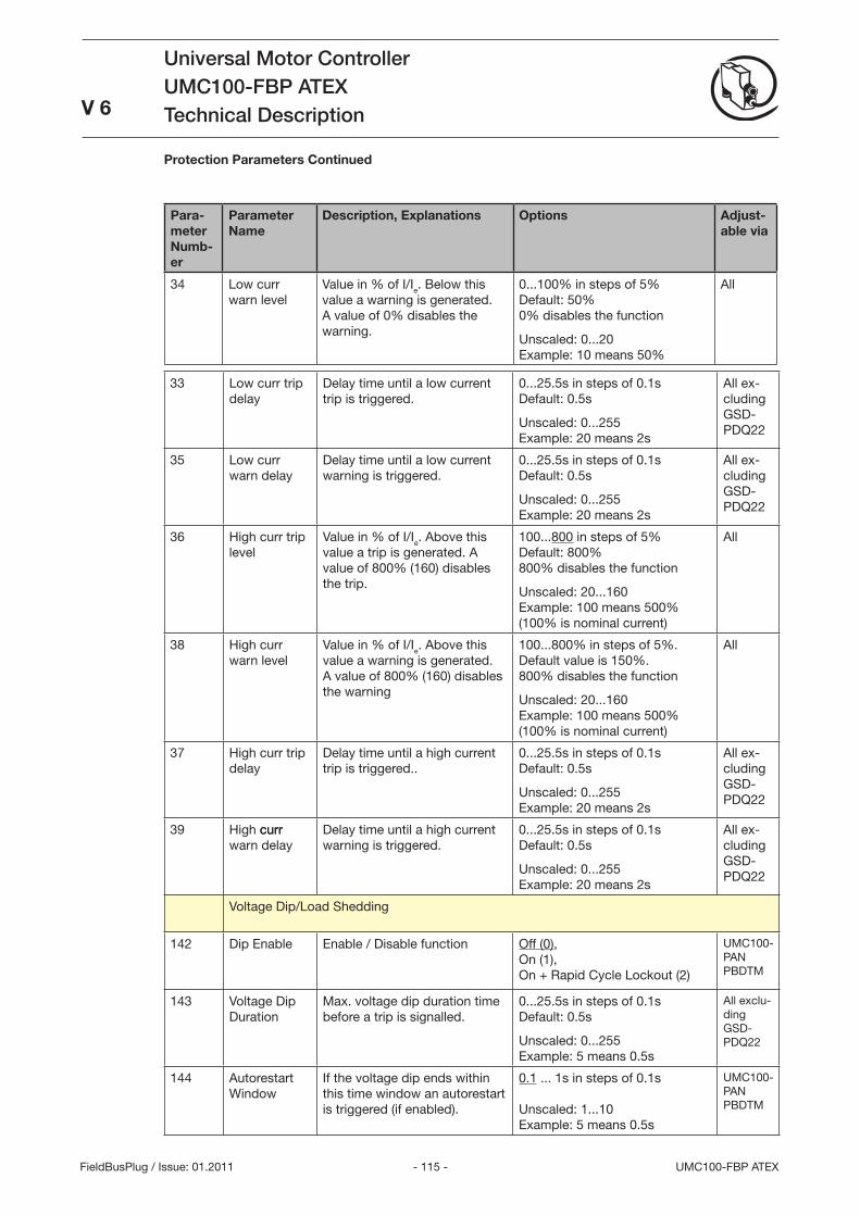
- 115 - UMC100-FBP ATEX
Universal Motor ControllerUMC100-FBP ATEXTechnical Description
V 6
FieldBusPlug / Issue: 01.2011
Para-meter Numb-er
Parameter Name
Description, Explanations Options Adjust-able via
4 Low curr warn level
Value in % of I/Ie. Below this value a warning is generated. A value of 0% disables the warning.
0...100% in steps of 5% Default: 50% 0% disables the function
Unscaled: 0...20 Example: 10 means 50%
All
Low curr trip delay
Delay time until a low current trip is triggered.
0...25.5s in steps of 0.1s Default: 0.5s
Unscaled: 0...255 Example: 20 means 2s
All ex-cluding GSD-PDQ22
5 Low curr warn delay
Delay time until a low current warning is triggered.
0...25.5s in steps of 0.1s Default: 0.5s
Unscaled: 0...255 Example: 20 means 2s
All ex-cluding GSD-PDQ22
6 High curr trip level
Value in % of I/Ie. Above this value a trip is generated. A value of 800% (160) disables the trip.
100...800 in steps of 5% Default: 800% 800% disables the function
Unscaled: 20...160 Example: 100 means 500% (100% is nominal current)
All
8 High curr warn level
Value in % of I/Ie. Above this value a warning is generated. A value of 800% (160) disables the warning
100...800% in steps of 5%. Default value is 150%. 800% disables the function
Unscaled: 20...160 Example: 100 means 500% (100% is nominal current)
All
7 High curr trip delay
Delay time until a high current trip is triggered..
0...25.5s in steps of 0.1s Default: 0.5s
Unscaled: 0...255 Example: 20 means 2s
All ex-cluding GSD-PDQ22
9 High currcurr warn delay
Delay time until a high current warning is triggered.
0...25.5s in steps of 0.1s Default: 0.5s
Unscaled: 0...255 Example: 20 means 2s
All ex-cluding GSD-PDQ22
Voltage Dip/Load Shedding
142 Dip Enable Enable / Disable function Off (0), On (1), On + Rapid Cycle Lockout (2)
UMC100-PAN PBDTM
14 Voltage Dip Duration
Max. voltage dip duration time before a trip is signalled.
0...25.5s in steps of 0.1s Default: 0.5s
Unscaled: 0...255 Example: 5 means 0.5s
All exclu-ding GSD-PDQ22
144 Autorestart Window
If the voltage dip ends within this time window an autorestart is triggered (if enabled).
0.1 ... 1s in steps of 0.1s Unscaled: 1...10 Example: 5 means 0.5s
UMC100-PAN PBDTM
Protection Parameters Continued
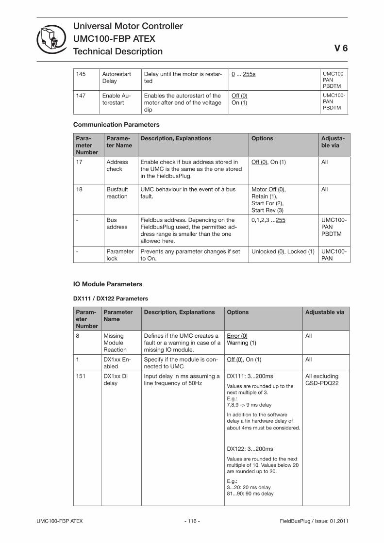
- 116 -UMC100-FBP ATEX
Universal Motor ControllerUMC100-FBP ATEXTechnical Description
V 6
FieldBusPlug / Issue: 01.2011
145 Autorestart Delay
Delay until the motor is restar-ted
0 ... 255s UMC100-PAN PBDTM
147 Enable Au-torestart
Enables the autorestart of the motor after end of the voltage dip
Off (0) On (1)
UMC100-PAN PBDTM
Communication Parameters
Para-meter Number
Parame-ter Name
Description, Explanations Options Adjusta-ble via
17 Address check
Enable check if bus address stored in the UMC is the same as the one stored in the FieldbusPlug.
Off (0), On (1) All
18 Busfault reaction
UMC behaviour in the event of a bus fault.
Motor Off (0), Retain (1), Start For (2), Start Rev ()
All
- Bus address
Fieldbus address. Depending on the FieldbusPlug used, the permitted ad-dress range is smaller than the one allowed here.
0,1,2, ...255 UMC100-PAN PBDTM
- Parameter lock
Prevents any parameter changes if set to On.
Unlocked (0), Locked (1) UMC100-PAN
IO Module Parameters
DX111 / DX122 Parameters
Param-eter Number
Parameter Name
Description, Explanations Options Adjustable via
8 Missing Module Reaction
Defines if the UMC creates a fault or a warning in case of a missing IO module.
Error (0) Warning (1)
All
1 DX1xx En-abled
Specify if the module is con-nected to UMC
Off (0), On (1) All
151 DX1xx DI delay
Input delay in ms assuming a line frequency of 50Hz
DX111: ...200ms
Values are rounded up to the next multiple of . E.g.: 7,8,9 -> 9 ms delay
In addition to the software delay a fix hardware delay of about 4ms must be considered.
DX122: ...200ms
Values are rounded to the next multiple of 10. Values below 20 are rounded up to 20.
E.g.: ...20: 20 ms delay 81...90: 90 ms delay
All excluding GSD-PDQ22
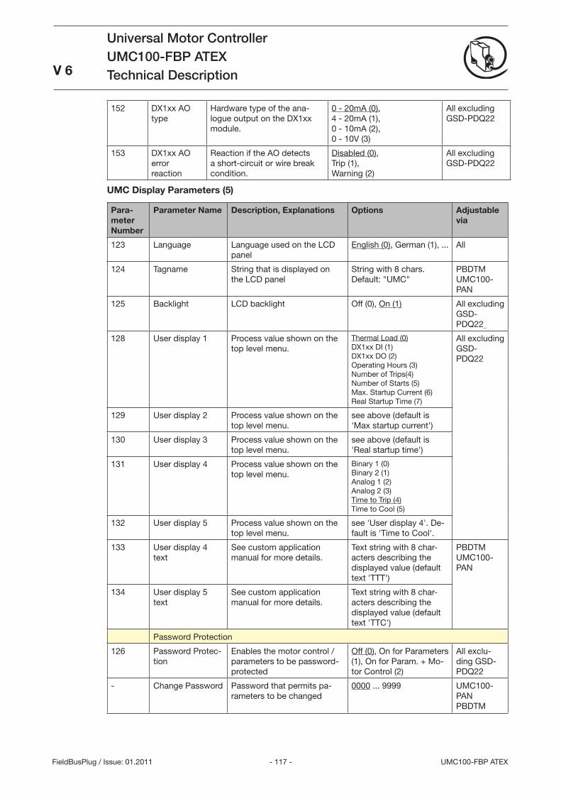
- 117 - UMC100-FBP ATEX
Universal Motor ControllerUMC100-FBP ATEXTechnical Description
V 6
FieldBusPlug / Issue: 01.2011
152 DX1xx AO type
Hardware type of the ana-logue output on the DX1xx module.
0 - 20mA (0), 4 - 20mA (1), 0 - 10mA (2), 0 - 10V ()
All excluding GSD-PDQ22
15 DX1xx AO error reaction
Reaction if the AO detects a short-circuit or wire break condition.
Disabled (0), Trip (1), Warning (2)
All excluding GSD-PDQ22
UMC Display Parameters (5)
Para-meter Number
Parameter Name Description, Explanations Options Adjustable via
12 Language Language used on the LCD panel
English (0), German (1), ... All
124 Tagname String that is displayed on the LCD panel
String with 8 chars. Default: UMC
PBDTM UMC100-PAN
125 Backlight LCD backlight Off (0), On (1) All excluding GSD-PDQ22
128 User display 1 Process value shown on the top level menu.
Thermal Load (0) DX1xx DI (1) DX1xx DO (2) Operating Hours () Number of Trips(4) Number of Starts (5) Max. Startup Current (6) Real Startup Time (7)
All excluding GSD-PDQ22
129 User display 2 Process value shown on the top level menu.
see above (default is 'Max startup current')
10 User display Process value shown on the top level menu.
see above (default is 'Real startup time')
11 User display 4 Process value shown on the top level menu.
Binary 1 (0) Binary 2 (1) Analog 1 (2) Analog 2 () Time to Trip (4) Time to Cool (5)
12 User display 5 Process value shown on the top level menu.
see 'User display 4'. De-fault is 'Time to Cool'.
1 User display 4 text
See custom application manual for more details.
Text string with 8 char-acters describing the displayed value (default text 'TTT')
PBDTM UMC100-PAN
14 User display 5 text
See custom application manual for more details.
Text string with 8 char-acters describing the displayed value (default text 'TTC')
Password Protection
126 Password Protec-tion
Enables the motor control / parameters to be password-protected
Off (0), On for Parameters (1), On for Param. + Mo-tor Control (2)
All exclu-ding GSD-PDQ22
- Change Password Password that permits pa-rameters to be changed
0000 ... 9999 UMC100-PAN PBDTM
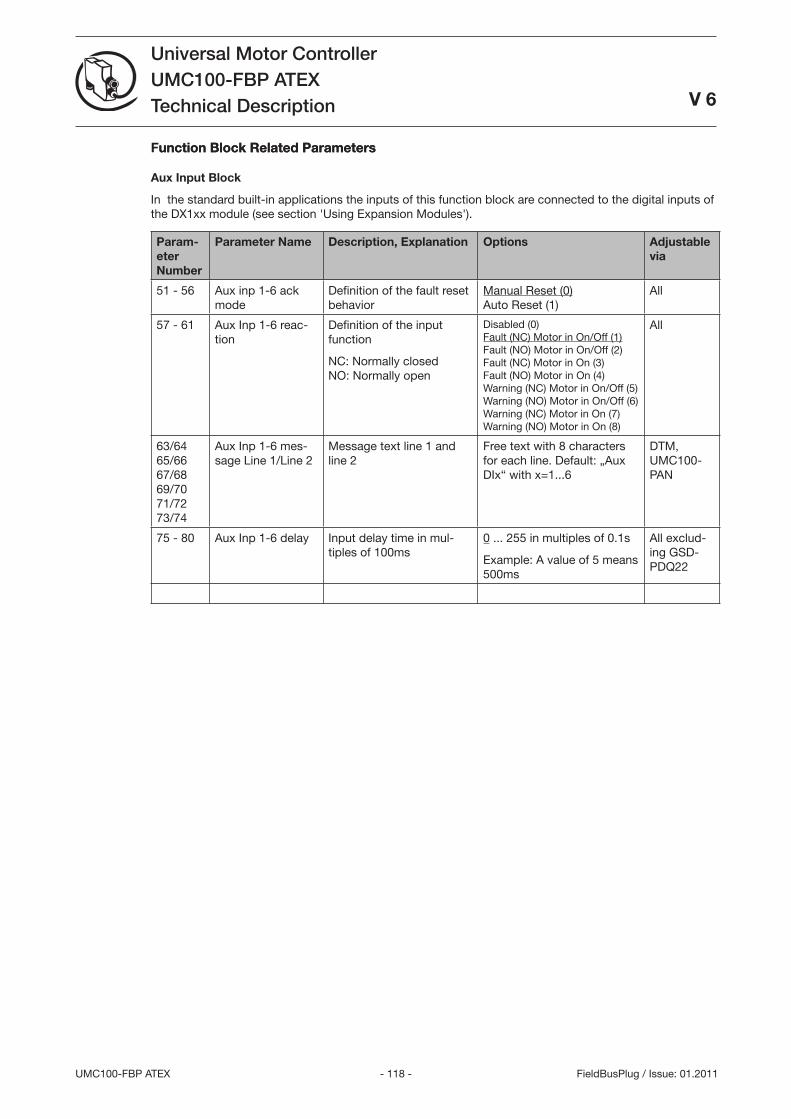
- 118 -UMC100-FBP ATEX
Universal Motor ControllerUMC100-FBP ATEXTechnical Description
V 6
FieldBusPlug / Issue: 01.2011
Function Block Related Parametersunction Block Related Parameters
Aux Input Block
In the standard built-in applications the inputs of this function block are connected to the digital inputs of the DX1xx module (see section 'Using Expansion Modules').
Param-eter Number
Parameter Name Description, Explanation Options Adjustable via
51 - 56 Aux inp 1-6 ack mode
Definition of the fault reset behavior
Manual Reset (0) Auto Reset (1)
All
57 - 61 Aux Inp 1-6 reac-tion
Definition of the input function
NC: Normally closed NO: Normally open
Disabled (0) Fault (NC) Motor in On/Off (1) Fault (NO) Motor in On/Off (2) Fault (NC) Motor in On () Fault (NO) Motor in On (4) Warning (NC) Motor in On/Off (5) Warning (NO) Motor in On/Off (6) Warning (NC) Motor in On (7) Warning (NO) Motor in On (8)
All
6/64 65/66 67/68 69/70 71/72 7/74
Aux Inp 1-6 mes-sage Line 1/Line 2
Message text line 1 and line 2
Free text with 8 characters for each line. Default: „Aux DIx“ with x=1...6
DTM, UMC100-PAN
75 - 80 Aux Inp 1-6 delay Input delay time in mul-tiples of 100ms
0 ... 255 in multiples of 0.1s
Example: A value of 5 means 500ms
All exclud-ing GSD-PDQ22
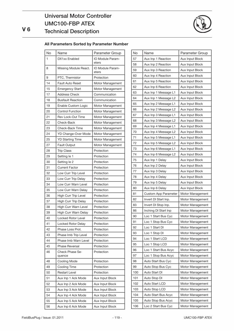
- 119 - UMC100-FBP ATEX
Universal Motor ControllerUMC100-FBP ATEXTechnical Description
V 6
FieldBusPlug / Issue: 01.2011
All Parameters Sorted by Parameter Number
No Name Parameter Group
1 DX1xx Enabled IO Module Param-eters
8 Missing Module React. IO Module Param-eters
9 PTC, Thermistor Protection
14 Fault Auto Reset Motor Management
15 Emergency Start Motor Management
17 Address Check Communication
18 Busfault Reaction Communication
19 Enable Custom Logic Motor Management
20 Control Function Motor Management
21 Rev Lock-Out Time Motor Management
22 Check-Back Motor Management
2 Check-Back Time Motor Management
24 YD Change-Over Mode Motor Management
25 YD Starting Time Motor Management
27 Fault Output Motor Management
28 Trip Class Protection
29 Setting Ie 1 Protection
0 Setting Ie 2 Protection
1 Current Factor Protection
2 Low Curr Trip Level Protection
Low Curr Trip Delay Protection
4 Low Curr Warn Level Protection
5 Low Curr Warn Delay Protection
6 High Curr Trip Level Protection
7 High Curr Trip Delay Protection
8 High Curr Warn Level Protection
9 High Curr Warn Delay Protection
40 Locked Rotor Level Protection
41 Locked Rotor Delay Protection
42 Phase Loss Prot. Protection
4 Phase Imb Trip Level Protection
44 Phase Imb Warn Level Protection
45 Phase Reversal Protection
46 Check Phase Se-quence
Protection
48 Cooling Mode Protection
49 Cooling Time Protection
50 Restart Level Protection
51 Aux Inp 1 Ack Mode Aux Input Block
52 Aux Inp 2 Ack Mode Aux Input Block
5 Aux Inp Ack Mode Aux Input Block
54 Aux Inp 4 Ack Mode Aux Input Block
55 Aux Inp 5 Ack Mode Aux Input Block
56 Aux Inp 6 Ack Mode Aux Input Block
No Name Parameter Group
57 Aux Inp 1 Reaction Aux Input Block
58 Aux Inp 2 Reaction Aux Input Block
59 Aux Inp Reaction Aux Input Block
60 Aux Inp 4 Reaction Aux Input Block
61 Aux Inp 5 Reaction Aux Input Block
62 Aux Inp 6 Reaction Aux Input Block
6 Aux Inp 1 Message L1 Aux Input Block
64 Aux Inp 1 Message L2 Aux Input Block
65 Aux Inp 2 Message L1 Aux Input Block
66 Aux Inp 2 Message L2 Aux Input Block
67 Aux Inp Message L1 Aux Input Block
68 Aux Inp Message L2 Aux Input Block
69 Aux Inp 4 Message L1 Aux Input Block
70 Aux Inp 4 Message L2 Aux Input Block
71 Aux Inp 5 Message L1 Aux Input Block
72 Aux Inp 5 Message L2 Aux Input Block
7 Aux Inp 6 Message L1 Aux Input Block
74 Aux Inp 6 Message L2 Aux Input Block
75 Aux Inp 1 Delay Aux Input Block
76 Aux Inp 2 Delay Aux Input Block
77 Aux Inp Delay Aux Input Block
78 Aux Inp 4 Delay Aux Input Block
79 Aux Inp 5 Delay Aux Input Block
80 Aux Inp 6 Delay Aux Input Block
81 Custom App Parameter Motor Management
82 Invert DI Start Inp. Motor Management
8 Invert DI Stop Inp. Motor Management
86 Inching DI Start Inp Motor Management
90 Loc 1 Start Bus Cyc Motor Management
91 Loc 1 Stop Bus Cyc Motor Management
92 Loc 1 Start DI Motor Management
9 Loc 1 Stop DI Motor Management
94 Loc 1 Start LCD Motor Management
95 Loc 1 Stop LCD Motor Management
96 Loc 1 Start Bus Acyc Motor Management
97 Loc 1 Stop Bus Acyc Motor Management
98 Auto Start Bus Cyc Motor Management
99 Auto Stop Bus Cyc Motor Management
100 Auto Start DI Motor Management
101 Auto Stop DI Motor Management
102 Auto Start LCD Motor Management
10 Auto Stop LCD Motor Management
104 Auto Start Bus Acyc Motor Management
105 Auto Stop Bus Acyc Motor Management
106 Loc 2 Start Bus Cyc Motor Management
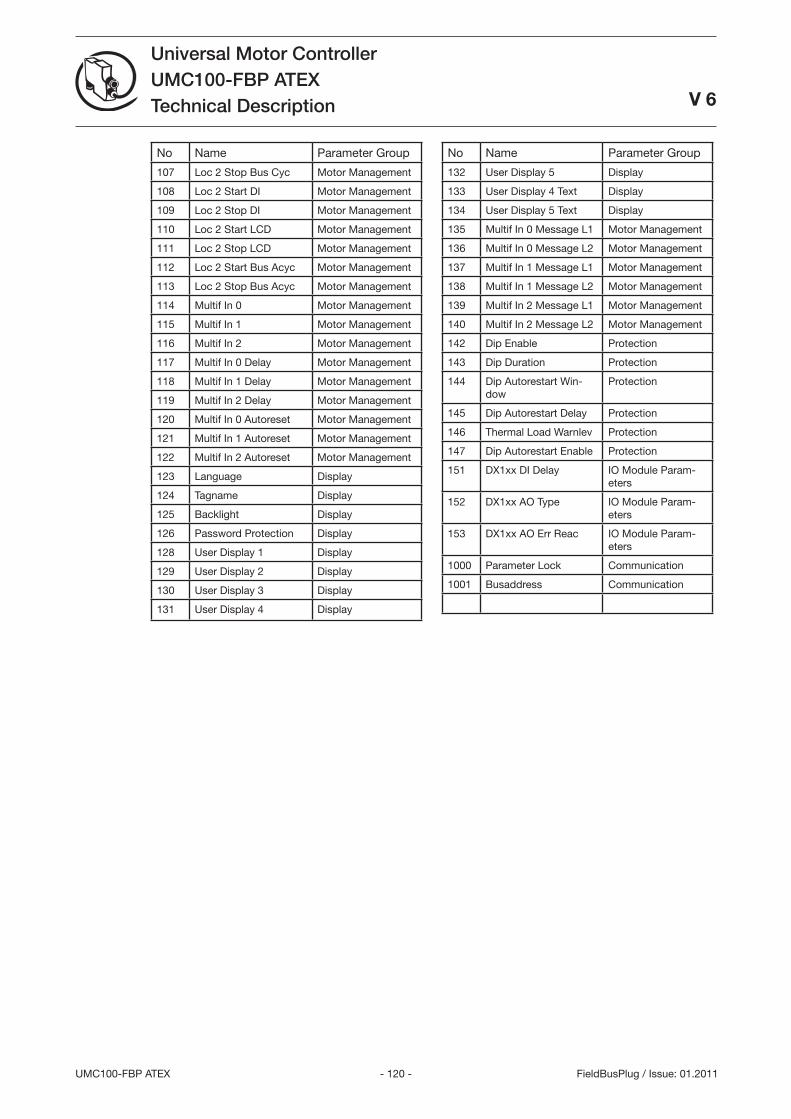
- 120 -UMC100-FBP ATEX
Universal Motor ControllerUMC100-FBP ATEXTechnical Description
V 6
FieldBusPlug / Issue: 01.2011
No Name Parameter Group
107 Loc 2 Stop Bus Cyc Motor Management
108 Loc 2 Start DI Motor Management
109 Loc 2 Stop DI Motor Management
110 Loc 2 Start LCD Motor Management
111 Loc 2 Stop LCD Motor Management
112 Loc 2 Start Bus Acyc Motor Management
11 Loc 2 Stop Bus Acyc Motor Management
114 Multif In 0 Motor Management
115 Multif In 1 Motor Management
116 Multif In 2 Motor Management
117 Multif In 0 Delay Motor Management
118 Multif In 1 Delay Motor Management
119 Multif In 2 Delay Motor Management
120 Multif In 0 Autoreset Motor Management
121 Multif In 1 Autoreset Motor Management
122 Multif In 2 Autoreset Motor Management
12 Language Display
124 Tagname Display
125 Backlight Display
126 Password Protection Display
128 User Display 1 Display
129 User Display 2 Display
10 User Display Display
11 User Display 4 Display
No Name Parameter Group
12 User Display 5 Display
1 User Display 4 Text Display
14 User Display 5 Text Display
15 Multif In 0 Message L1 Motor Management
16 Multif In 0 Message L2 Motor Management
17 Multif In 1 Message L1 Motor Management
18 Multif In 1 Message L2 Motor Management
19 Multif In 2 Message L1 Motor Management
140 Multif In 2 Message L2 Motor Management
142 Dip Enable Protection
14 Dip Duration Protection
144 Dip Autorestart Win-dow
Protection
145 Dip Autorestart Delay Protection
146 Thermal Load Warnlev Protection
147 Dip Autorestart Enable Protection
151 DX1xx DI Delay IO Module Param-eters
152 DX1xx AO Type IO Module Param-eters
15 DX1xx AO Err Reac IO Module Param-eters
1000 Parameter Lock Communication
1001 Busaddress Communication
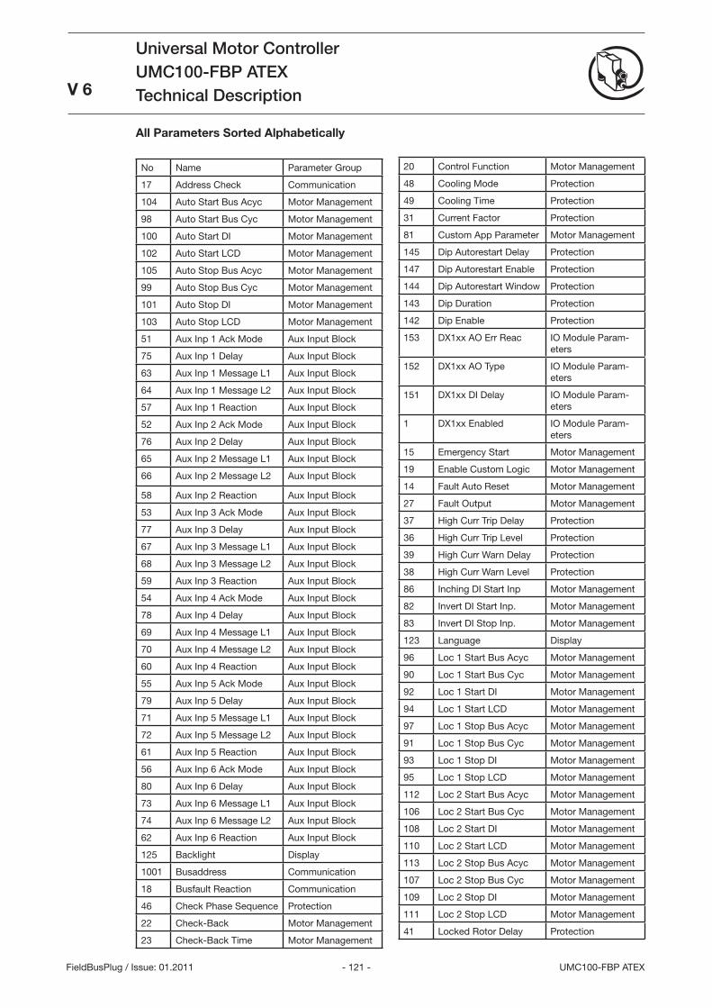
- 121 - UMC100-FBP ATEX
Universal Motor ControllerUMC100-FBP ATEXTechnical Description
V 6
FieldBusPlug / Issue: 01.2011
All Parameters Sorted Alphabetically
No Name Parameter Group
17 Address Check Communication
104 Auto Start Bus Acyc Motor Management
98 Auto Start Bus Cyc Motor Management
100 Auto Start DI Motor Management
102 Auto Start LCD Motor Management
105 Auto Stop Bus Acyc Motor Management
99 Auto Stop Bus Cyc Motor Management
101 Auto Stop DI Motor Management
10 Auto Stop LCD Motor Management
51 Aux Inp 1 Ack Mode Aux Input Block
75 Aux Inp 1 Delay Aux Input Block
6 Aux Inp 1 Message L1 Aux Input Block
64 Aux Inp 1 Message L2 Aux Input Block
57 Aux Inp 1 Reaction Aux Input Block
52 Aux Inp 2 Ack Mode Aux Input Block
76 Aux Inp 2 Delay Aux Input Block
65 Aux Inp 2 Message L1 Aux Input Block
66 Aux Inp 2 Message L2 Aux Input Block
58 Aux Inp 2 Reaction Aux Input Block
5 Aux Inp Ack Mode Aux Input Block
77 Aux Inp Delay Aux Input Block
67 Aux Inp Message L1 Aux Input Block
68 Aux Inp Message L2 Aux Input Block
59 Aux Inp Reaction Aux Input Block
54 Aux Inp 4 Ack Mode Aux Input Block
78 Aux Inp 4 Delay Aux Input Block
69 Aux Inp 4 Message L1 Aux Input Block
70 Aux Inp 4 Message L2 Aux Input Block
60 Aux Inp 4 Reaction Aux Input Block
55 Aux Inp 5 Ack Mode Aux Input Block
79 Aux Inp 5 Delay Aux Input Block
71 Aux Inp 5 Message L1 Aux Input Block
72 Aux Inp 5 Message L2 Aux Input Block
61 Aux Inp 5 Reaction Aux Input Block
56 Aux Inp 6 Ack Mode Aux Input Block
80 Aux Inp 6 Delay Aux Input Block
7 Aux Inp 6 Message L1 Aux Input Block
74 Aux Inp 6 Message L2 Aux Input Block
62 Aux Inp 6 Reaction Aux Input Block
125 Backlight Display
1001 Busaddress Communication
18 Busfault Reaction Communication
46 Check Phase Sequence Protection
22 Check-Back Motor Management
2 Check-Back Time Motor Management
20 Control Function Motor Management
48 Cooling Mode Protection
49 Cooling Time Protection
1 Current Factor Protection
81 Custom App Parameter Motor Management
145 Dip Autorestart Delay Protection
147 Dip Autorestart Enable Protection
144 Dip Autorestart Window Protection
14 Dip Duration Protection
142 Dip Enable Protection
15 DX1xx AO Err Reac IO Module Param-eters
152 DX1xx AO Type IO Module Param-eters
151 DX1xx DI Delay IO Module Param-eters
1 DX1xx Enabled IO Module Param-eters
15 Emergency Start Motor Management
19 Enable Custom Logic Motor Management
14 Fault Auto Reset Motor Management
27 Fault Output Motor Management
7 High Curr Trip Delay Protection
6 High Curr Trip Level Protection
9 High Curr Warn Delay Protection
8 High Curr Warn Level Protection
86 Inching DI Start Inp Motor Management
82 Invert DI Start Inp. Motor Management
8 Invert DI Stop Inp. Motor Management
12 Language Display
96 Loc 1 Start Bus Acyc Motor Management
90 Loc 1 Start Bus Cyc Motor Management
92 Loc 1 Start DI Motor Management
94 Loc 1 Start LCD Motor Management
97 Loc 1 Stop Bus Acyc Motor Management
91 Loc 1 Stop Bus Cyc Motor Management
9 Loc 1 Stop DI Motor Management
95 Loc 1 Stop LCD Motor Management
112 Loc 2 Start Bus Acyc Motor Management
106 Loc 2 Start Bus Cyc Motor Management
108 Loc 2 Start DI Motor Management
110 Loc 2 Start LCD Motor Management
11 Loc 2 Stop Bus Acyc Motor Management
107 Loc 2 Stop Bus Cyc Motor Management
109 Loc 2 Stop DI Motor Management
111 Loc 2 Stop LCD Motor Management
41 Locked Rotor Delay Protection
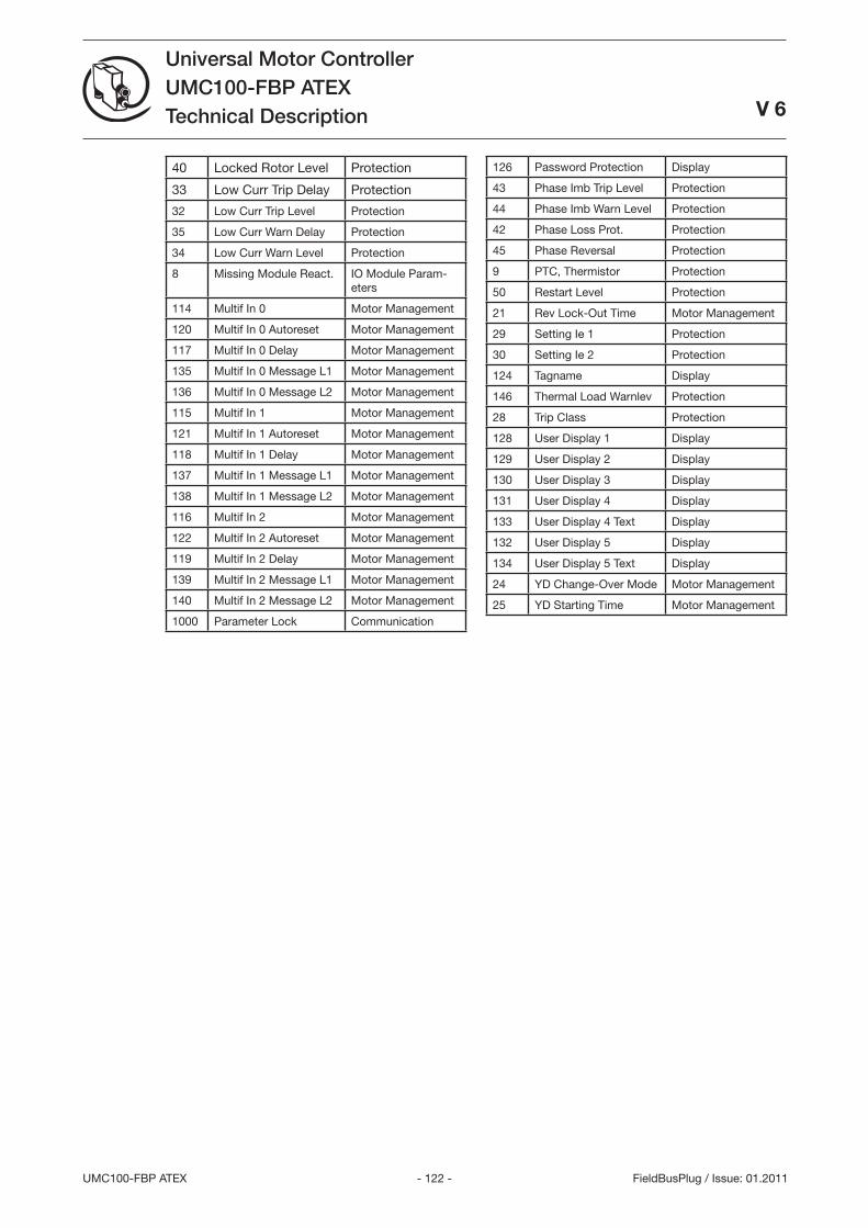
- 122 -UMC100-FBP ATEX
Universal Motor ControllerUMC100-FBP ATEXTechnical Description
V 6
FieldBusPlug / Issue: 01.2011
40 Locked Rotor Level Protection
Low Curr Trip Delay Protection
2 Low Curr Trip Level Protection
5 Low Curr Warn Delay Protection
4 Low Curr Warn Level Protection
8 Missing Module React. IO Module Param-eters
114 Multif In 0 Motor Management
120 Multif In 0 Autoreset Motor Management
117 Multif In 0 Delay Motor Management
15 Multif In 0 Message L1 Motor Management
16 Multif In 0 Message L2 Motor Management
115 Multif In 1 Motor Management
121 Multif In 1 Autoreset Motor Management
118 Multif In 1 Delay Motor Management
17 Multif In 1 Message L1 Motor Management
18 Multif In 1 Message L2 Motor Management
116 Multif In 2 Motor Management
122 Multif In 2 Autoreset Motor Management
119 Multif In 2 Delay Motor Management
19 Multif In 2 Message L1 Motor Management
140 Multif In 2 Message L2 Motor Management
1000 Parameter Lock Communication
126 Password Protection Display
4 Phase Imb Trip Level Protection
44 Phase Imb Warn Level Protection
42 Phase Loss Prot. Protection
45 Phase Reversal Protection
9 PTC, Thermistor Protection
50 Restart Level Protection
21 Rev Lock-Out Time Motor Management
29 Setting Ie 1 Protection
0 Setting Ie 2 Protection
124 Tagname Display
146 Thermal Load Warnlev Protection
28 Trip Class Protection
128 User Display 1 Display
129 User Display 2 Display
10 User Display Display
11 User Display 4 Display
1 User Display 4 Text Display
12 User Display 5 Display
14 User Display 5 Text Display
24 YD Change-Over Mode Motor Management
25 YD Starting Time Motor Management
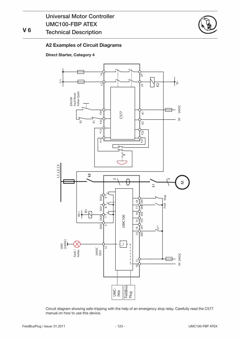
- 12 - UMC100-FBP ATEX
Universal Motor ControllerUMC100-FBP ATEXTechnical Description
V 6
FieldBusPlug / Issue: 01.2011
L1, L
2, L
3
3
K1
k1
DO
CD
O0
DO
1D
O2
24V
DC
1011
57
89
24V
DC
DO
3
12
13
14
15
1
6
17
1
8
DI0
D
I1
DI2
D
I3
DI4
D
I5
UM
C10
0
UM
C-
PAN
Fiel
db
us
Plu
g
0V
I Lim
Fwd
Sto
p
k1*
GN
D(2
4VD
C)
M
3
24V
DC
A1
Y11
Y12
Y21
Y22
A2
0V
EIN
/ON
Fau
lt R
eset
Feh
ler Q
uit
t.
k2
L/+
Y33
Y34
K1
K2
1314
2324
K2 N
/-
k1
(N/-
)
C57
7
Fau
lt /
Feh
ler
A2 Examples of Circuit Diagrams
Direct Starter, Category 4
Circuit diagram showing safe-tripping with the help of an emergency stop relay. Carefully read the C577 manual on how to use this device.
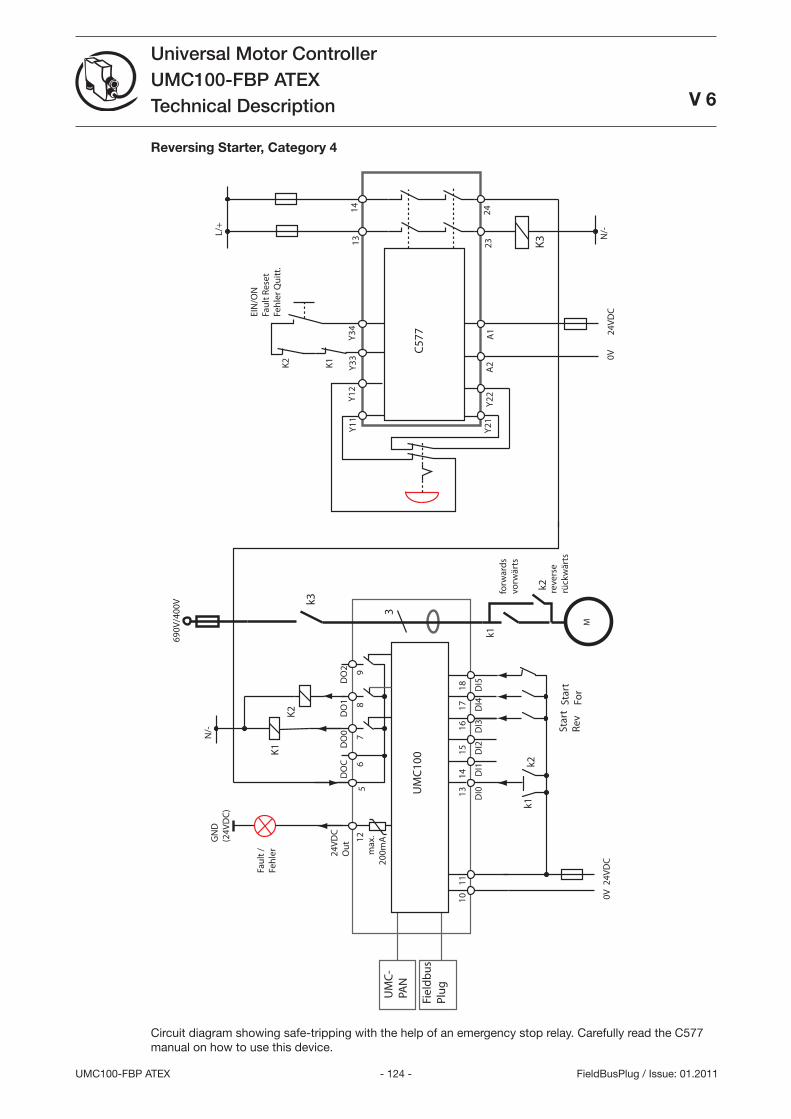
- 124 -UMC100-FBP ATEX
Universal Motor ControllerUMC100-FBP ATEXTechnical Description
V 6
FieldBusPlug / Issue: 01.2011
M
3
DO
CD
O0
DO
1D
O2
24V
DC
1011
67
89
24V
DC
Ou
t 12
13
14
15
1
6
17
1
8
DI0
D
I1
DI2
D
I3
DI4
D
I5
UM
C10
0
UM
C-
PAN
Fiel
db
us
Plu
g
0V
GN
D(2
4VD
C)
690V
/400
V
5
reve
rse
rück
wär
ts
max
.20
0mA
Star
tFo
r
Star
tR
ev
K1
K2
k2
k1fo
rwar
ds
vorw
ärts
k1k2
24V
DC
A1
Y11
Y12
Y21
Y22
A2
0V
EIN
/ON
Fau
lt R
eset
Feh
ler Q
uit
t.
L/+
Y33
Y34
K1
K2
1314
2324
K3 N
/-
C57
7
N/-
Fau
lt /
Feh
ler
k3
Reversing Starter, Category 4
Circuit diagram showing safe-tripping with the help of an emergency stop relay. Carefully read the C577 manual on how to use this device.
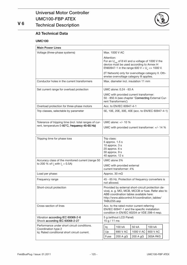
- 125 - UMC100-FBP ATEX
Universal Motor ControllerUMC100-FBP ATEXTechnical Description
V 6
FieldBusPlug / Issue: 01.2011
A3 Technical Data
UMC100
Main Power Lines
Voltage (three-phase systems) Max. 1000 V AC
Attention: For an Uimp of 8 kV and a voltage of 1000 V the device must be used according to Annex H EN60947-1 in the range 600 V < Ue <= 1000 V.
(IT Network) only for overvoltage category II. Oth-erwise overvoltage category III applies.
Conductor holes in the current transformers Max. diameter incl. insulation 11 mm
Set current range for overload protection UMC alone: 0.24 - 6 A
UMC with provided current transformer: 50 - 850 A (see chapter 'ConnectingConnecting External Cur-rent Transformers'))
Overload protection for three-phase motors Acc. to EN/IEC 60947-4-1
Trip classes, selectable by parameter 5E, 10E, 20E, 0E, 40E (acc. to EN/IEC 60947-4-1)
Tolerance of tripping time (incl. total ranges of cur-rent, temperature 0-60°C, frequency 45-65 Hz)60°C, frequency 45-65 Hz), frequency 45-65 Hz)
UMC alone: +/- 10 %
UMC with provided current transformer: +/- 14 %
Tripping time for phase loss Trip class: 5 approx. 1.5 s 10 approx. s 20 approx. 6 s 0 approx. 9 s 40 approx. 12 s
Accuracy class of the monitored current (range 50 to 200 % of Ie with Ie > 0.5A)
UMC alone %
UMC with provided external current transformer: 4%
Load per phase: Approx. 0 mΩ
Frequency range 45 - 65 Hz. Protection of frequency converters is not allowed.
Short-circuit protection Provided by external short-circuit protection de-vice), e. g. MO, MCB, MCCB or fuse. Refer also to ABB coordination tables available here: http://www.abbcontrol.fr/coordination_tables/TABLES5.asp
Cross-section of lines Acc. to the rated motor current referring EN/IEC 60947-1 and the specific installation condition in EN/IEC 60204 or VDE 298-4 resp.
Vibration according IEC 60068-2-6according IEC 60068-2-6 Shock according IEC 60068-2-27according IEC 60068-2-27
5 g (without LCD Panel) 15 g / 11 ms
Performance under short circuit conditions. Coordination type 2 Iq: Rated conditional short circuit current.
Iq 100 kA 50 kA 100 kA
Up 690 V AC 1000 V AC 600 V AC
Fuse 200 A gG 200 A gG 00A RK5
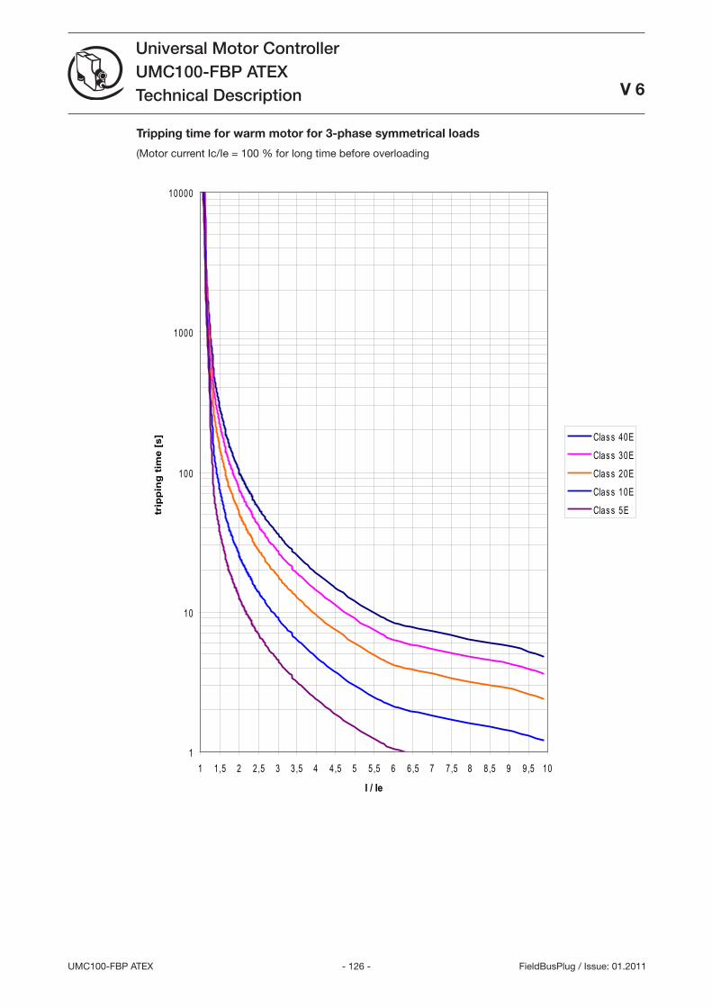
- 126 -UMC100-FBP ATEX
Universal Motor ControllerUMC100-FBP ATEXTechnical Description
V 6
FieldBusPlug / Issue: 01.2011
Tripping time for warm motor for 3-phase symmetrical loads
(Motor current Ic/Ie = 100 % for long time before overloading
1
10
100
1000
10000
1 1,5 2 2,5 3 3,5 4 4,5 5 5,5 6 6,5 7 7,5 8 8,5 9 9,5 10
I / Ie
trip
pin
g t
ime
[s] Clas s 40E
Clas s 30EClas s 20EClas s 10EClas s 5E
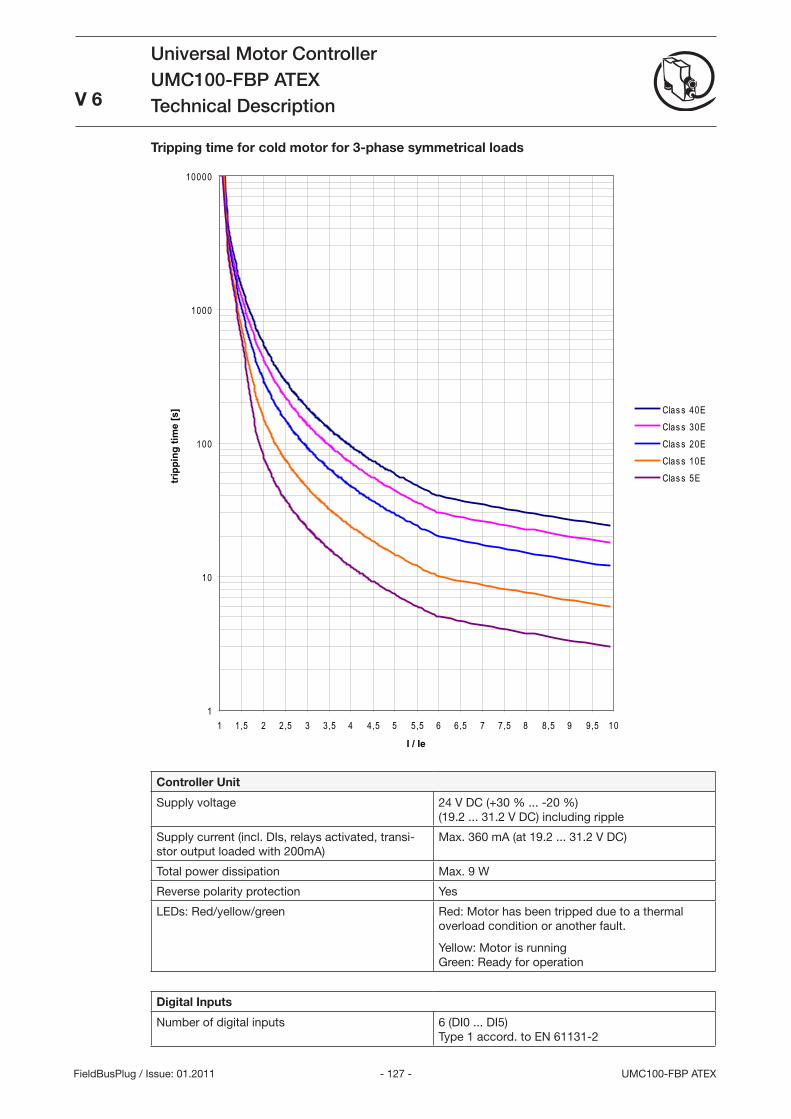
- 127 - UMC100-FBP ATEX
Universal Motor ControllerUMC100-FBP ATEXTechnical Description
V 6
FieldBusPlug / Issue: 01.2011
Controller Unit
Supply voltage 24 V DC (+0 % ... -20 %) (19.2 ... 1.2 V DC) including ripple
Supply current (incl. DIs, relays activated, transi-stor output loaded with 200mA)
Max. 60 mA (at 19.2 ... 1.2 V DC)
Total power dissipation Max. 9 W
Reverse polarity protection Yes
LEDs: Red/yellow/green Red: Motor has been tripped due to a thermal overload condition or another fault.
Yellow: Motor is running Green: Ready for operation
Digital Inputs
Number of digital inputs 6 (DI0 ... DI5) Type 1 accord. to EN 6111-2
Tripping time for cold motor for 3-phase symmetrical loads
1
10
100
1000
10000
1 1,5 2 2,5 3 3,5 4 4,5 5 5,5 6 6,5 7 7,5 8 8,5 9 9,5 10
I / Ie
trip
ping
tim
e [s
] Clas s 40EClas s 30EClas s 20EClas s 10EClas s 5E
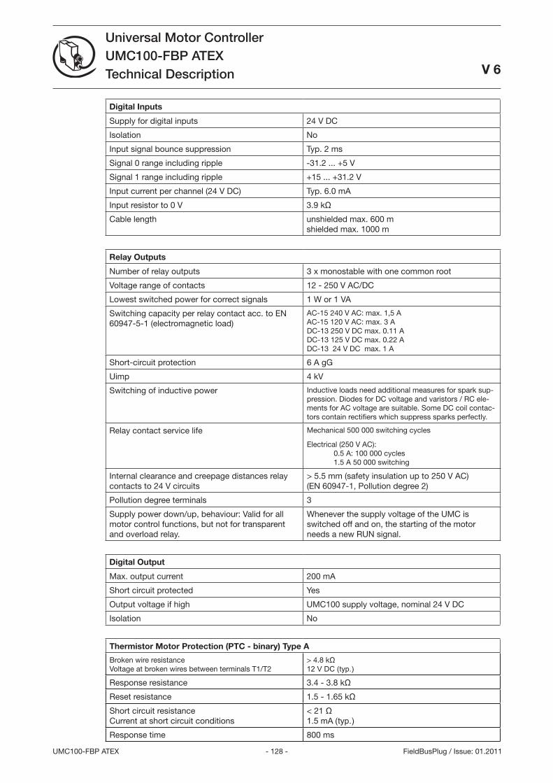
- 128 -UMC100-FBP ATEX
Universal Motor ControllerUMC100-FBP ATEXTechnical Description
V 6
FieldBusPlug / Issue: 01.2011
Digital Inputs
Supply for digital inputs 24 V DC
Isolation No
Input signal bounce suppression Typ. 2 ms
Signal 0 range including ripple -1.2 ... +5 V
Signal 1 range including ripple +15 ... +1.2 V
Input current per channel (24 V DC) Typ. 6.0 mA
Input resistor to 0 V .9 kΩ
Cable length unshielded max. 600 m shielded max. 1000 m
Relay Outputs
Number of relay outputs x monostable with one common root
Voltage range of contacts 12 - 250 V AC/DC
Lowest switched power for correct signals 1 W or 1 VA
Switching capacity per relay contact acc. to EN 60947-5-1 (electromagnetic load)
AC-15 240 V AC: max. 1,5 A AC-15 120 V AC: max. A DC-1 250 V DC max. 0.11 A DC-1 125 V DC max. 0.22 A DC-1 24 V DC max. 1 A
Short-circuit protection 6 A gG
Uimp 4 kV
Switching of inductive power Inductive loads need additional measures for spark sup-pression. Diodes for DC voltage and varistors / RC ele-ments for AC voltage are suitable. Some DC coil contac-tors contain rectifiers which suppress sparks perfectly.
Relay contact service life Mechanical 500 000 switching cycles
Electrical (250 V AC): 0.5 A: 100 000 cycles 1.5 A 50 000 switching
Internal clearance and creepage distances relay contacts to 24 V circuits
> 5.5 mm (safety insulation up to 250 V AC) (EN 60947-1, Pollution degree 2)
Pollution degree terminals
Supply power down/up, behaviour: Valid for all motor control functions, but not for transparent and overload relay.
Whenever the supply voltage of the UMC is switched off and on, the starting of the motor needs a new RUN signal.
Digital Output
Max. output current 200 mA
Short circuit protected Yes
Output voltage if high UMC100 supply voltage, nominal 24 V DC
Isolation No
Thermistor Motor Protection (PTC - binary) Type A
Broken wire resistance Voltage at broken wires between terminals T1/T2
> 4.8 kΩ 12 V DC (typ.)
Response resistance .4 - .8 kΩ
Reset resistance 1.5 - 1.65 kΩ
Short circuit resistance Current at short circuit conditions
< 21 Ω 1.5 mA (typ.)
Response time 800 ms
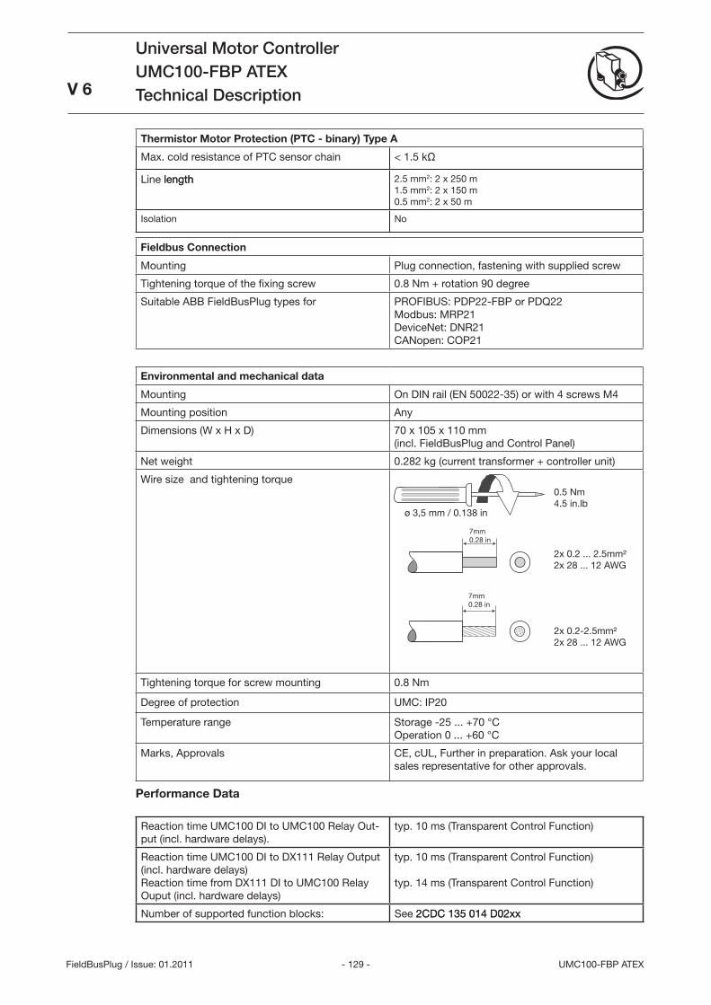
- 129 - UMC100-FBP ATEX
Universal Motor ControllerUMC100-FBP ATEXTechnical Description
V 6
FieldBusPlug / Issue: 01.2011
Thermistor Motor Protection (PTC - binary) Type A
Max. cold resistance of PTC sensor chain < 1.5 kΩ
Line lengthlength 2.5 mm2: 2 x 250 m 1.5 mm2: 2 x 150 m 0.5 mm2: 2 x 50 m
Isolation No
Fieldbus Connection
Mounting Plug connection, fastening with supplied screw
Tightening torque of the fixing screw 0.8 Nm + rotation 90 degree
Suitable ABB FieldBusPlug types for PROFIBUS: PDP22-FBP or PDQ22 Modbus: MRP21 DeviceNet: DNR21 CANopen: COP21
Environmental and mechanical data
Mounting On DIN rail (EN 50022-5) or with 4 screws M4
Mounting position Any
Dimensions (W x H x D) 70 x 105 x 110 mm (incl. FieldBusPlug and Control Panel)
Net weight 0.282 kg (current transformer + controller unit)
Wire size and tightening torque
Tightening torque for screw mounting 0.8 Nm
Degree of protection UMC: IP20
Temperature range Storage -25 ... +70 °C Operation 0 ... +60 °C
Marks, Approvals CE, cUL, Further in preparation. Ask your local sales representative for other approvals.
Performance Data
Reaction time UMC100 DI to UMC100 Relay Out-put (incl. hardware delays).
typ. 10 ms (Transparent Control Function)
Reaction time UMC100 DI to DX111 Relay Output (incl. hardware delays) Reaction time from DX111 DI to UMC100 Relay Ouput (incl. hardware delays)
typ. 10 ms (Transparent Control Function) typ. 14 ms (Transparent Control Function)
Number of supported function blocks: See 2CDC 15 014 D02xx2CDC 15 014 D02xx
ø ,5 mm / 0.18 in
0.5 Nm 4.5 in.lb
2x 0.2 ... 2.5mm² 2x 28 ... 12 AWG
7mm 0.28 in
7mm 0.28 in
2x 0.2-2.5mm² 2x 28 ... 12 AWG
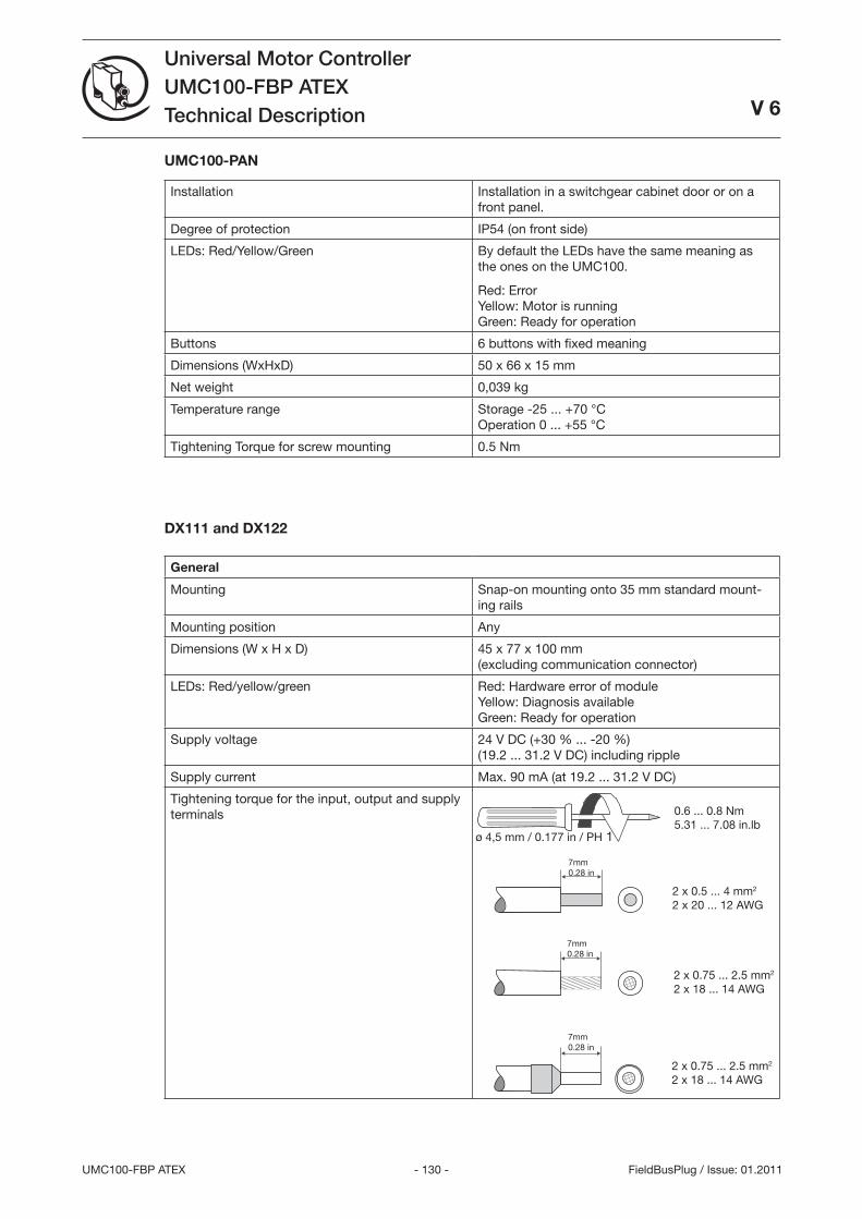
- 10 -UMC100-FBP ATEX
Universal Motor ControllerUMC100-FBP ATEXTechnical Description
V 6
FieldBusPlug / Issue: 01.2011
UMC100-PAN
Installation Installation in a switchgear cabinet door or on a front panel.
Degree of protection IP54 (on front side)
LEDs: Red/Yellow/Green By default the LEDs have the same meaning as the ones on the UMC100.
Red: Error Yellow: Motor is running Green: Ready for operation
Buttons 6 buttons with fixed meaning
Dimensions (WxHxD) 50 x 66 x 15 mm
Net weight 0,09 kg
Temperature range Storage -25 ... +70 °C Operation 0 ... +55 °C
Tightening Torque for screw mounting 0.5 Nm
DX111 and DX122
General
Mounting Snap-on mounting onto 5 mm standard mount-ing rails
Mounting position Any
Dimensions (W x H x D) 45 x 77 x 100 mm (excluding communication connector)
LEDs: Red/yellow/green Red: Hardware error of module Yellow: Diagnosis available Green: Ready for operation
Supply voltage 24 V DC (+0 % ... -20 %) (19.2 ... 1.2 V DC) including ripple
Supply current Max. 90 mA (at 19.2 ... 1.2 V DC)
Tightening torque for the input, output and supply terminals
ø 4,5 mm / 0.177 in / PH 1
0.6 ... 0.8 Nm 5.1 ... 7.08 in.lb
2 x 0.5 ... 4 mm2 2 x 20 ... 12 AWG
2 x 0.75 ... 2.5 mm2 2 x 18 ... 14 AWG
2 x 0.75 ... 2.5 mm2 2 x 18 ... 14 AWG
7mm 0.28 in
7mm 0.28 in
7mm 0.28 in
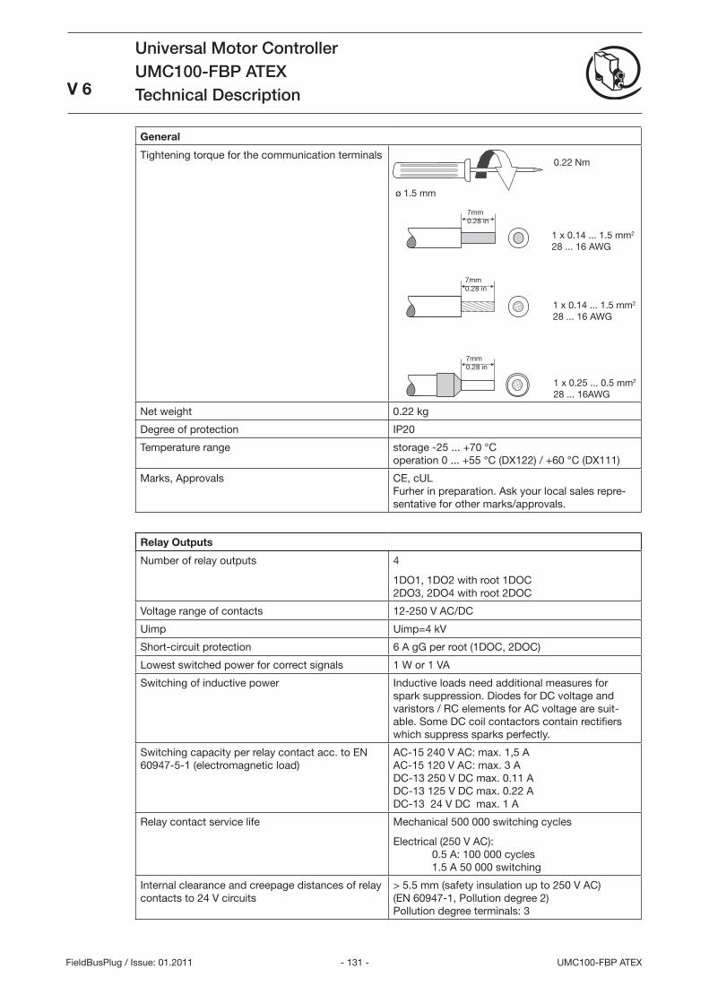
- 11 - UMC100-FBP ATEX
Universal Motor ControllerUMC100-FBP ATEXTechnical Description
V 6
FieldBusPlug / Issue: 01.2011
0.22 Nm
1 x 0.14 ... 1.5 mm2 28 ... 16 AWG
1 x 0.14 ... 1.5 mm2 28 ... 16 AWG
1 x 0.25 ... 0.5 mm2 28 ... 16AWG
7mm 0.28 in
7mm 0.28 in
7mm 0.28 in
General
Tightening torque for the communication terminals
Net weight 0.22 kg
Degree of protection IP20
Temperature range storage -25 ... +70 °C operation 0 ... +55 °C (DX122) / +60 °C (DX111)
Marks, Approvals CE, cUL Furher in preparation. Ask your local sales repre-sentative for other marks/approvals.
Relay Outputs
Number of relay outputs 4
1DO1, 1DO2 with root 1DOC 2DO, 2DO4 with root 2DOC
Voltage range of contacts 12-250 V AC/DC
Uimp Uimp=4 kV
Short-circuit protection 6 A gG per root (1DOC, 2DOC)
Lowest switched power for correct signals 1 W or 1 VA
Switching of inductive power Inductive loads need additional measures for spark suppression. Diodes for DC voltage and varistors / RC elements for AC voltage are suit-able. Some DC coil contactors contain rectifiers which suppress sparks perfectly.
Switching capacity per relay contact acc. to EN 60947-5-1 (electromagnetic load)
AC-15 240 V AC: max. 1,5 A AC-15 120 V AC: max. A DC-1 250 V DC max. 0.11 A DC-1 125 V DC max. 0.22 A DC-1 24 V DC max. 1 A
Relay contact service life Mechanical 500 000 switching cycles
Electrical (250 V AC): 0.5 A: 100 000 cycles 1.5 A 50 000 switching
Internal clearance and creepage distances of relay contacts to 24 V circuits
> 5.5 mm (safety insulation up to 250 V AC) (EN 60947-1, Pollution degree 2) Pollution degree terminals:
ø 1.5 mm
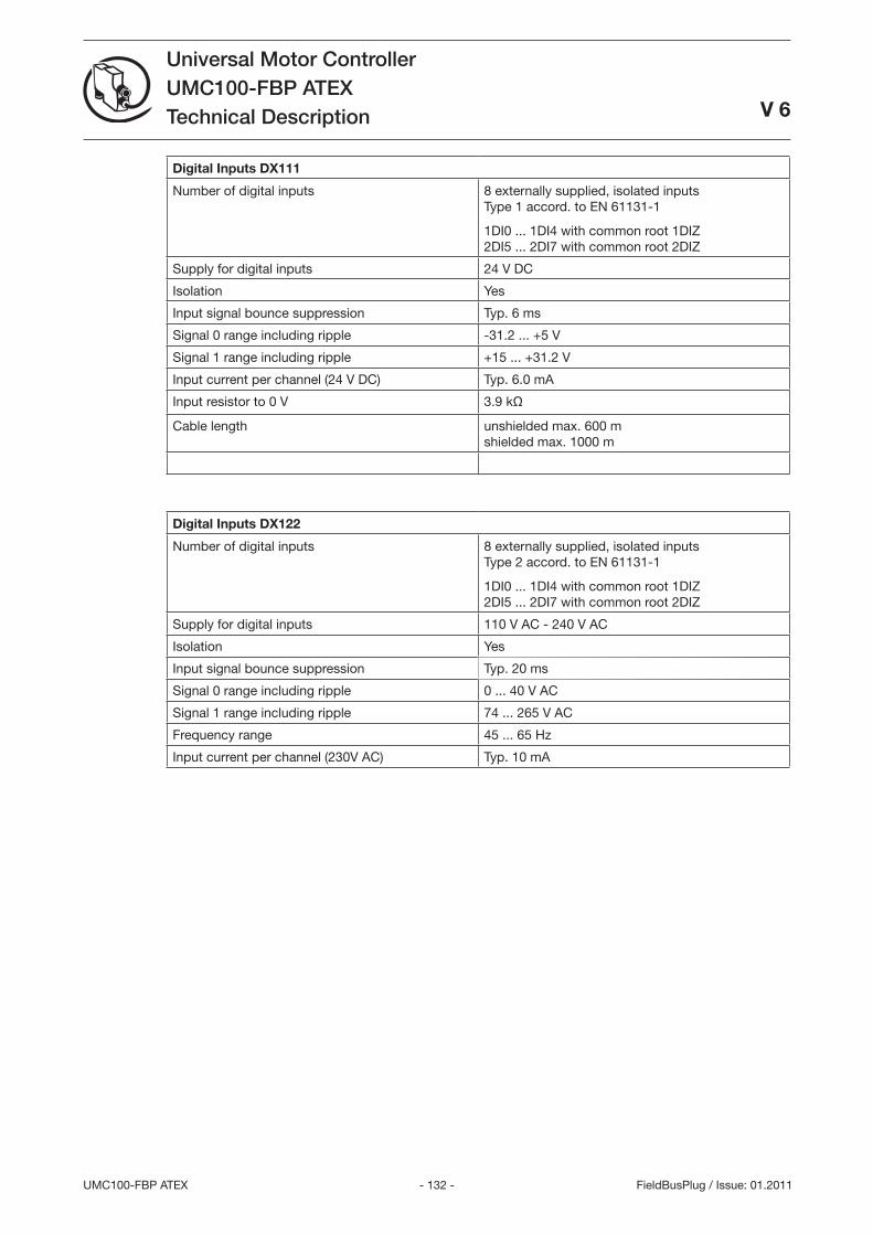
- 12 -UMC100-FBP ATEX
Universal Motor ControllerUMC100-FBP ATEXTechnical Description
V 6
FieldBusPlug / Issue: 01.2011
Digital Inputs DX111
Number of digital inputs 8 externally supplied, isolated inputs Type 1 accord. to EN 6111-1
1DI0 ... 1DI4 with common root 1DIZ 2DI5 ... 2DI7 with common root 2DIZ
Supply for digital inputs 24 V DC
Isolation Yes
Input signal bounce suppression Typ. 6 ms
Signal 0 range including ripple -1.2 ... +5 V
Signal 1 range including ripple +15 ... +1.2 V
Input current per channel (24 V DC) Typ. 6.0 mA
Input resistor to 0 V .9 kΩ
Cable length unshielded max. 600 m shielded max. 1000 m
Digital Inputs DX122
Number of digital inputs 8 externally supplied, isolated inputs Type 2 accord. to EN 6111-1
1DI0 ... 1DI4 with common root 1DIZ 2DI5 ... 2DI7 with common root 2DIZ
Supply for digital inputs 110 V AC - 240 V AC
Isolation Yes
Input signal bounce suppression Typ. 20 ms
Signal 0 range including ripple 0 ... 40 V AC
Signal 1 range including ripple 74 ... 265 V AC
Frequency range 45 ... 65 Hz
Input current per channel (20V AC) Typ. 10 mA
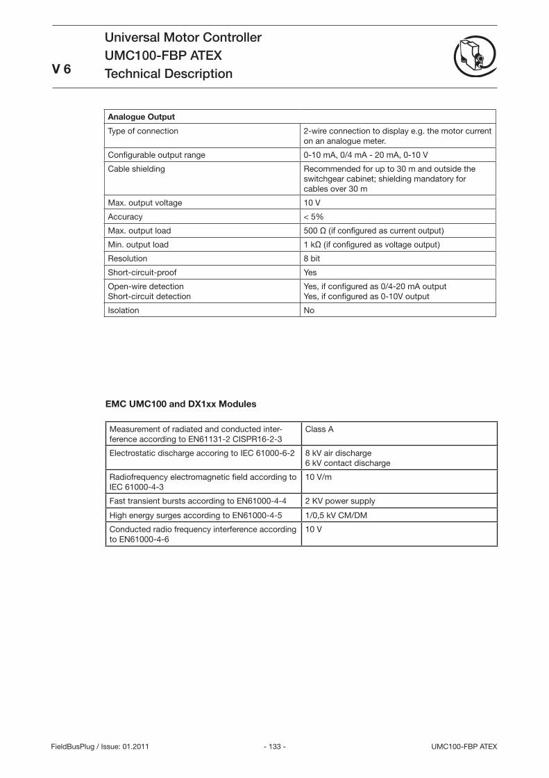
- 1 - UMC100-FBP ATEX
Universal Motor ControllerUMC100-FBP ATEXTechnical Description
V 6
FieldBusPlug / Issue: 01.2011
EMC UMC100 and DX1xx Modules
Measurement of radiated and conducted inter-ference according to EN6111-2 CISPR16-2-
Class A
Electrostatic discharge accoring to IEC 61000-6-2 8 kV air discharge 6 kV contact discharge
Radiofrequency electromagnetic field according to IEC 61000-4-
10 V/m
Fast transient bursts according to EN61000-4-4 2 KV power supply
High energy surges according to EN61000-4-5 1/0,5 kV CM/DM
Conducted radio frequency interference according to EN61000-4-6
10 V
Analogue Output
Type of connection 2-wire connection to display e.g. the motor current on an analogue meter.
Configurable output range 0-10 mA, 0/4 mA - 20 mA, 0-10 V
Cable shielding Recommended for up to 0 m and outside the switchgear cabinet; shielding mandatory for cables over 0 m
Max. output voltage 10 V
Accuracy < 5%
Max. output load 500 Ω (if configured as current output)
Min. output load 1 kΩ (if configured as voltage output)
Resolution 8 bit
Short-circuit-proof Yes
Open-wire detection Short-circuit detection
Yes, if configured as 0/4-20 mA output Yes, if configured as 0-10V output
Isolation No
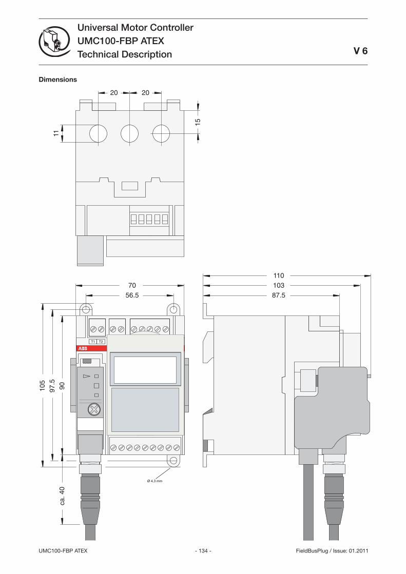
- 14 -UMC100-FBP ATEX
Universal Motor ControllerUMC100-FBP ATEXTechnical Description
V 6
FieldBusPlug / Issue: 01.2011
56.5
90
87.570
97.5
105
ca. 4
0
103110
11
20 20
15
181716151413121110
DIDIDIDIDIDI
24V
240543210OutVV
Power
T1
8
DO1
7
DO0
6
DOC
5
DOC
9
DO2
8765 9T2 3 4
UMC22
READY
MOT.ON
FAULT
.
Relay
230VAC1A
Inputs24VDC
DC
Ø 4,3 mm
Dimensions
- 15 - UMC100-FBP ATEX
Universal Motor ControllerUMC100-FBP ATEXTechnical Description
FieldBusPlug / Issue: 01.2011
Detected an Error?Your feedback helps us to constantly improve our products. We are grateful for your comments and suggestions. Please provide us with the following information if you have noticed an issue:
Name
Company / Department
Telephone / Email
Problem Description
Steps to reproduce the problem
Version of UMC (Ident number on nameplate and firmware version which is displayed on the UMC100-PAN)
Version of PBDTM (ControlPanel->Sofware) / AssetVisionBasic (Help->About) / Windows (Control->System)
•
•
•
FAX No.: +49 (0) 6221-701-1382
- 16 -UMC100-FBP ATEX
Universal Motor ControllerUMC100-FBP ATEXTechnical Description
FieldBusPlug / Issue: 01.2011

ABB STOTZ-KONTAKT GmbHP. O. Box 10 16 0 069006 Heidelberg, Germany
Phone: +49 (0) 6221 7 01-0Fax: +49 (0) 6221 7 01-240 E-Mail: [email protected] http://www.abb.de/stotzkontakt
Contact
Note:We reserve the right to make technical changes or modify the contents of this document without prior notice. With regard to purchase orders, the agreed particulars shall prevail. ABB AG does not accept any responsibility whatsoever for potential errors or possible lack of information in this document.
We reserve all rights in this document and in the subject matter and illustrations contained therein. Any reproduction, disclosure to third parties or utilization of its contents – in whole or in parts – is forbidden without prior written consent of ABB AG.
Copyright© 2010 ABB All rights reserved
2CD
C 1
5 0
21 D
0201
01.2
011
0
1.20
11