Embed Size (px)
Citation preview

Programmable Logic Devices FPGA Architectures II CMPE 415
1 (10/4/05)UMBCU M B C
UN
IVE
RSI
TY
OF
MARYLAND BALTIM
OR
E C
OU
NTY
1 9 6 6
OverviewThis set of notes introduces many of the features available in the FPGAs oftoday.
The majority use SRAM based configuration cells, which allows fast recon-figuation.
• Allows new design ideas to be quickly implemented and tested.• Allows evolving standards and protocols to be accommodated.• Allows the FPGA to carry out multiple functions, such as self-test or
board/system test at power-up and something else later.
Another advantage of using SRAM is that SRAM technology is very heavilyinvested in, and therefore, FPGA companies can leverage this.
Also, the same process used to fabricate the logic gates on the FPGA is usedto fabricate SRAM -- no special processing steps are needed.
The drawback of SRAM is volatility, which is overcome with a special exter-nal memory device or microprocessor (costly either way).

Programmable Logic Devices FPGA Architectures II CMPE 415
2 (10/4/05)UMBCU M B C
UN
IVE
RSI
TY
OF
MARYLAND BALTIM
OR
E C
OU
NTY
1 9 6 6
SecurityAnother concern with SRAM-based FPGAs is that it can be difficult to protectyour intellectual property.
The configuration file lives somewhere on disk, in memory, etc.
At this point, there is no commercially available tool that can read the con-tents of the configuration file and generate a schematic or netlist.
However, it is not rocket science to accomplish this (although it’s not trivialeither).
Also, bear in mind, there are reverse-engineering companies all over theworld.
In many cases, it is not even necessary for them to understand the detailsof your design.
They can use a bed-of-nails tester to extract a complete netlist of yourboard and then copy the FPGA configuration file from its boot PROM.

Programmable Logic Devices FPGA Architectures II CMPE 415
3 (10/4/05)UMBCU M B C
UN
IVE
RSI
TY
OF
MARYLAND BALTIM
OR
E C
OU
NTY
1 9 6 6
SecurityToday, there are SRAM-based FPGAs that support the concept of bitstreamencryption.
Here, the configuration file is encrypted before being stored in the PROM.
The encryption key is loaded into a special SRAM-based register in the FPGAvia its JTAG port.
The key is used to decrypt the bitstream as it is loaded into the FPGA.
The drawback is that a battery backup is needed to maintain the contents ofthe encryption key register.
Antifuse-based devicesAntifuse-based FPGAs are programmed off-line using a special chip pro-grammer.
Advantages include:• Configuration is retained during power cycle (non-volatile).

Programmable Logic Devices FPGA Architectures II CMPE 415
4 (10/4/05)UMBCU M B C
UN
IVE
RSI
TY
OF
MARYLAND BALTIM
OR
E C
OU
NTY
1 9 6 6
Antifuse-Based ChipsAdvantages (cont.)• They don’t require an external memory to store their configuration data,
which saves on board cost and real estate.
• Their interconnect structure is "rad hard", or relatively immune to the effectsof radiation.
Note that any FFs in these FPGAs remain sensitive to random flips dueto radiation, and must be protected using triple redundancy design.
• Lastly, the configuration data is buried deep inside them.By default, it is possible for the chip programmer to read this data out.
This is necessary during programming in order to know when to moveon to the next antifuse, and afterwards for verification.
Once programmed, it is possible to grow a special security antifuse thatprevents the presence or absence of antifuses to be read out.
Programmable Logic Devices FPGA Architectures II CMPE 415
5 (10/4/05)UMBCU M B C
UN
IVE
RSI
TY
OF
MARYLAND BALTIM
OR
E C
OU
NTY
1 9 6 6
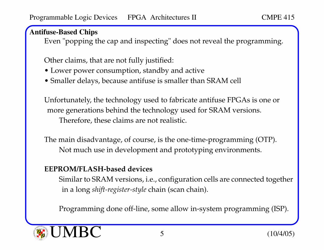
Antifuse-Based ChipsEven "popping the cap and inspecting" does not reveal the programming.
Other claims, that are not fully justified:• Lower power consumption, standby and active• Smaller delays, because antifuse is smaller than SRAM cell
Unfortunately, the technology used to fabricate antifuse FPGAs is one ormore generations behind the technology used for SRAM versions.
Therefore, these claims are not realistic.
The main disadvantage, of course, is the one-time-programming (OTP).Not much use in development and prototyping environments.
EEPROM/FLASH-based devicesSimilar to SRAM versions, i.e., configuration cells are connected togetherin a long shift-register-style chain (scan chain).
Programming done off-line, some allow in-system programming (ISP).

Programmable Logic Devices FPGA Architectures II CMPE 415
6 (10/4/05)UMBCU M B C
UN
IVE
RSI
TY
OF
MARYLAND BALTIM
OR
E C
OU
NTY
1 9 6 6
EEPROM/FLASH-Based ChipsHowever, programming time is about 3 times longer than SRAM version.
For security, some use a multibit key (50 to several hundred bits).Once programmed, you load a user-defined key to secure your data.
Once the key is loaded, reading and writing require that your key beloaded via the JTAG port.
Two-transistor EEPROM and FLASH cells are about 2.5 times larger than theone-transistor EPROM cells (no one currently makes an EPROM version).
They are still much smaller than SRAM, reducing area and delay.
One drawback is that these devices require about 5 additional process stepsbeyond the standard CMOS process.
Similar to antifuse, this causes a lag of these devices, technology wise.
Also, they have high static power because of the internal pull-up resistors.

Programmable Logic Devices FPGA Architectures II CMPE 415
7 (10/4/05)UMBCU M B C
UN
IVE
RSI
TY
OF
MARYLAND BALTIM
OR
E C
OU
NTY
1 9 6 6
Hybrid FLASH-SRAM ChipsHere, each configuration element is formed from a combination of FLASH (orEEPROM) and an SRAM cell.
The FLASH elements are preprogrammed, whose contents, when poweredup, are massively transferred to the SRAM cells.
Provides non-volatility while powered off and speedy reconfigurability whenpowered up.
You should become familiar with the information in the following table.

Programmable Logic Devices FPGA Architectures II CMPE 415
8 (10/4/05)UMBCU M B C
UN
IVE
RSI
TY
OF
MARYLAND BALTIM
OR
E C
OU
NTY
1 9 6 6
Summary
The Design Warrior’s Guide to FPGAs,ISBN 0750676043,Copyright(C) 2004 Mentor Graphics Corp

Programmable Logic Devices FPGA Architectures II CMPE 415
9 (10/4/05)UMBCU M B C
UN
IVE
RSI
TY
OF
MARYLAND BALTIM
OR
E C
OU
NTY
1 9 6 6
Fine-, Medium-, and Course-Grained ArchitecturesBasic architecture consists of a large number of PLB islands embedded in asea of programmable interconnect.
The Design Warrior’s Guide to FPGAs,ISBN 0750676043,Copyright(C) 2004 Mentor Graphics Corp
Programmable Logic Devices FPGA Architectures II CMPE 415
10 (10/4/05)UMBCU M B C
UN
IVE
RSI
TY
OF
MARYLAND BALTIM
OR
E C
OU
NTY
1 9 6 6
Fine-, Medium-, and Course-Grained Architectures"Level of granularity", when used in the context of an FPGA refers to thecomplexity of the PLB.
The PLBs of fine-grained architectures can only implement simple functions,e.g., 3-input logic gate or storage element.
Good for glue logic, state machines, systolic algorithms (massively par-allel), and traditional logic synthesis.
The PLBs of medium-grained architectures include more logic and morefunctionality, i.e., a 4-input LUTs, 4 MUXs, 4 D-FFs + fast carry logic.
This helps with the interconnect problem, e.g., more "compute power"per wire dedicated for interconnections.
Large-grained architectures incorporate FFT engines and microprocessorcores.
Fine-grained architectures of the mid-90’s gave way to the medium grainedarchitectures.

Programmable Logic Devices FPGA Architectures II CMPE 415
11 (10/4/05)UMBCU M B C
UN
IVE
RSI
TY
OF
MARYLAND BALTIM
OR
E C
OU
NTY
1 9 6 6
MUX- vs. LUT-based Logic BlocksThere are 2 basic flavors of PLBs for medium-grained architectures, multiplexer(MUX) and lookup table (LUT).
In the MUX-based version, each input can be programmed with a logic 0, 1,or the true or inverted version of a variable.
The Design Warrior’s Guide to FPGAs,ISBN 0750676043,Copyright(C) 2004 Mentor Graphics Corp

Programmable Logic Devices FPGA Architectures II CMPE 415
12 (10/4/05)UMBCU M B C
UN
IVE
RSI
TY
OF
MARYLAND BALTIM
OR
E C
OU
NTY
1 9 6 6
MUX- vs. LUT-based Logic BlocksMost FPGAs today are LUT-based -- here, the input signals are used as apointer into a lookup table.
Input signals can be decoded using a hierarchy of transmission-gate MUXs.
Transmission gates pass the value on their inputs or are high-impedance.
Note that the diagram does not show the serial connection of the cells (scanchain) for simplicity.
The Design Warrior’s Guide to FPGAs,ISBN 0750676043,Copyright(C) 2004 Mentor Graphics Corp

Programmable Logic Devices FPGA Architectures II CMPE 415
13 (10/4/05)UMBCU M B C
UN
IVE
RSI
TY
OF
MARYLAND BALTIM
OR
E C
OU
NTY
1 9 6 6
MUX- vs. LUT-based Logic BlocksLarger LUTs are possible, e.g., 3-, 4-, 5- and 6-input versions.
Every time an input is added, the size of the table doubles.
4-input versions are believed to provide the optimal balance today.
Some vendors allow the 16 cells in the LUT to play the role as a 16x1 RAM,and sets to be strewn together to form larger RAMs.
Some vendors allow the 16 cells of the LUT to be decoupled from the largerchain and used as a shift register.
The Design Warrior’s Guide to FPGAs,ISBN 0750676043,Copyright(C) 2004 Mentor Graphics Corp

Programmable Logic Devices FPGA Architectures II CMPE 415
14 (10/4/05)UMBCU M B C
UN
IVE
RSI
TY
OF
MARYLAND BALTIM
OR
E C
OU
NTY
1 9 6 6
TerminologyXilinx calls them logic cells (LC) while Altera calls them logic elements (LE).
A slice is defined as 2 LCs.Each instance has its own inputs and outputs but the clock, clock enable,and set/reset signals are common.
A configurable logic block (CLB, Xilinx) or logic array block (LAB, Altera).CLBs consist of 2 or 4 slices, and conform to the islands shown earlier.
The Design Warrior’s Guide to FPGAs,ISBN 0750676043,Copyright(C) 2004 Mentor Graphics Corp
Any one of severalfunctions

Programmable Logic Devices FPGA Architectures II CMPE 415
15 (10/4/05)UMBCU M B C
UN
IVE
RSI
TY
OF
MARYLAND BALTIM
OR
E C
OU
NTY
1 9 6 6
Terminology and HierarchyThe CLB also has some fast interconnect (not shown), that is used to connectneighboring slices.
The organization of LC -> Slice -> CLB is complemented by an equivalenthierarchy in the interconnect.
That is, fast interconnect between LCs in a slice, slightly slower betweenslices in a CLB, followed by the interconnect between LCBs.
The Design Warrior’s Guide to FPGAs,ISBN 0750676043,Copyright(C) 2004 Mentor Graphics Corp

Programmable Logic Devices FPGA Architectures II CMPE 415
16 (10/4/05)UMBCU M B C
UN
IVE
RSI
TY
OF
MARYLAND BALTIM
OR
E C
OU
NTY
1 9 6 6
FPGA Additional Features and CharacteristicsAssuming 4 slices per CLB, several RAM configurations are possible.• Single-port 16x8, 32x4 bit, 64x2 or 128x1 bit RAM• Dual-port 16x4, 32x2, 64x1 bit RAM (reads and writes occur through indi-
vidual ports)
The LCs of the slices and slices of the CLB contain special interconnect toallow the 16 bit shift registers of each LC to be combined into a 128 bit chain.
The LCs also include special carry logic (for fast carry chains), and dedicatedinterconnect between LCs in a slice, between slices and between CLBs.
These features boost the performance of logical functions, e.g., counters andadders.
Many applications require memory, so FPGAs now include embedded RAMcalled e-RAM or block RAM.

Programmable Logic Devices FPGA Architectures II CMPE 415
17 (10/4/05)UMBCU M B C
UN
IVE
RSI
TY
OF
MARYLAND BALTIM
OR
E C
OU
NTY
1 9 6 6
FPGA Additional Features and CharacteristicsSome FPGAs include these blocks around the periphery of the chip, othersdistribute the blocks, while others organized it in columns.
Each block can hold up to 10K bits, and each chip may contain hundreds ofthese eRAM blocks, for storage capacity up to several million bits.
The eRAM blocks can be used separately or combined, and are useful forimplementing single/dual-port RAMs, FIFO functions, state machines, etc.
The Design Warrior’s Guide to FPGAs,ISBN 0750676043,Copyright(C) 2004 Mentor Graphics Corp

Programmable Logic Devices FPGA Architectures II CMPE 415
18 (10/4/05)UMBCU M B C
UN
IVE
RSI
TY
OF
MARYLAND BALTIM
OR
E C
OU
NTY
1 9 6 6
FPGA Additional Features and CharacteristicsSome functions, like multipliers, are slow if implemented by connectingLCBs together.
Since these functions are common, many include special hardwired multi-plier blocks.
They are often located near the eRAM blocks.
The Design Warrior’s Guide to FPGAs,ISBN 0750676043,Copyright(C) 2004 Mentor Graphics Corp

Programmable Logic Devices FPGA Architectures II CMPE 415
19 (10/4/05)UMBCU M B C
UN
IVE
RSI
TY
OF
MARYLAND BALTIM
OR
E C
OU
NTY
1 9 6 6
FPGA Additional Features and CharacteristicsSome FPGAs offer dedicated adder blocks.
These are useful in DSP operations called multiply-and-accumulate(MAC).
This operation consists of multiplying two numbers and storing the result inas a running total (in the accumulator).
The Design Warrior’s Guide to FPGAs,ISBN 0750676043,Copyright(C) 2004 Mentor Graphics Corp