Embed Size (px)
Citation preview

December 2017 DocID029405 Rev 6 1/43
1
UM2073User manual
STM32 LoRa® software expansion for STM32Cube
Introduction
This user manual describes the LoRa® Expansion Package implementation on the STM32Lx Series; this software is called I-CUBE-LRWAN. This document also explains how to interface with the LoRaWAN™ to manage the LoRa® wireless link.
LoRa® is a type of wireless telecommunication network designed to allow long range communications at a very low bit-rate and enabling long-life battery operated sensors. LoRaWAN™ defines the communication and security protocol that ensures the interoperability with the LoRa® network.
The LoRa® Expansion Package is compliant with the LoRa Alliance™ specification protocol named LoRaWAN™.
The I-CUBE-LRWAN main features are the following:
• Application integration ready
• Easy add-on of the low-power LoRa® solution
• Extremely low CPU load
• No latency requirements
• Small STM32 memory footprint
• Low-power timing services provided
The I-CUBE-LRWAN Expansion Package is based on the STM32Cube HAL drivers (see Section 2).
This user manual provides customer application examples on NUCLEO-L053R8, NUCLEO-L152RE and NUCLEOL476RG using Semtech expansion boards SX1276MB1MAS, SX1276MB1LAS and SX1272MB2DAS.
This document targets the following tools:
• P-NUCLEO-LRWAN1, STM32 Nucleo pack for LoRa® technology
• B-L072Z-LRWAN1, STM32 Discovery kit embedding the CMWX1ZZABZ-091 LoRa® module (Murata)
• I-NUCLEO-LRWAN1, LoRa® expansion board for STM32 Nucleo, based on the WM-SG-SM-42 LPWAN module (USI®)
• LRWAN-NS1, expansion board featuring the RiSiNGHF® modem RHF0M003 available in P-NUCLEO-LRWAN3
www.st.com

Contents UM2073
2/43 DocID029405 Rev 6
Contents
1 Overview . . . . . . . . . . . . . . . . . . . . . . . . . . . . . . . . . . . . . . . . . . . . . . . . . . 7
1.1 Acronyms and abbreviations . . . . . . . . . . . . . . . . . . . . . . . . . . . . . . . . . . . 7
1.2 References . . . . . . . . . . . . . . . . . . . . . . . . . . . . . . . . . . . . . . . . . . . . . . . . . 7
2 LoRa standard overview . . . . . . . . . . . . . . . . . . . . . . . . . . . . . . . . . . . . . . 8
2.1 Overview . . . . . . . . . . . . . . . . . . . . . . . . . . . . . . . . . . . . . . . . . . . . . . . . . . 8
2.2 Network architecture . . . . . . . . . . . . . . . . . . . . . . . . . . . . . . . . . . . . . . . . . 8
2.2.1 End-device architecture . . . . . . . . . . . . . . . . . . . . . . . . . . . . . . . . . . . . . . 9
2.2.2 End-device classes . . . . . . . . . . . . . . . . . . . . . . . . . . . . . . . . . . . . . . . . . 9
2.2.3 End-device activation (joining) . . . . . . . . . . . . . . . . . . . . . . . . . . . . . . . . 10
2.2.4 Regional spectrum allocation . . . . . . . . . . . . . . . . . . . . . . . . . . . . . . . . . 11
2.3 Network layer . . . . . . . . . . . . . . . . . . . . . . . . . . . . . . . . . . . . . . . . . . . . . . .11
2.3.1 Physical layer (PHY) . . . . . . . . . . . . . . . . . . . . . . . . . . . . . . . . . . . . . . . 12
2.3.2 MAC sublayer . . . . . . . . . . . . . . . . . . . . . . . . . . . . . . . . . . . . . . . . . . . . 12
2.4 Message flow . . . . . . . . . . . . . . . . . . . . . . . . . . . . . . . . . . . . . . . . . . . . . . 12
2.4.1 End-device activation details (joining) . . . . . . . . . . . . . . . . . . . . . . . . . . 12
2.4.2 End-device data communication (class A) . . . . . . . . . . . . . . . . . . . . . . . 13
2.5 Data flow . . . . . . . . . . . . . . . . . . . . . . . . . . . . . . . . . . . . . . . . . . . . . . . . . 14
3 I-CUBE-LRWAN middleware description . . . . . . . . . . . . . . . . . . . . . . . 15
3.1 Overview . . . . . . . . . . . . . . . . . . . . . . . . . . . . . . . . . . . . . . . . . . . . . . . . . 15
3.2 Features . . . . . . . . . . . . . . . . . . . . . . . . . . . . . . . . . . . . . . . . . . . . . . . . . . 17
3.3 Architecture . . . . . . . . . . . . . . . . . . . . . . . . . . . . . . . . . . . . . . . . . . . . . . . 18
3.4 Hardware related components . . . . . . . . . . . . . . . . . . . . . . . . . . . . . . . . . 19
3.4.1 Radio reset . . . . . . . . . . . . . . . . . . . . . . . . . . . . . . . . . . . . . . . . . . . . . . 19
3.4.2 SPI . . . . . . . . . . . . . . . . . . . . . . . . . . . . . . . . . . . . . . . . . . . . . . . . . . . . . 19
3.4.3 RTC . . . . . . . . . . . . . . . . . . . . . . . . . . . . . . . . . . . . . . . . . . . . . . . . . . . . 19
3.4.4 Interrupt lines . . . . . . . . . . . . . . . . . . . . . . . . . . . . . . . . . . . . . . . . . . . . . 20
4 I-CUBE-LRWAN middleware programming guidelines . . . . . . . . . . . . 21
4.1 Middleware initialization . . . . . . . . . . . . . . . . . . . . . . . . . . . . . . . . . . . . . . 21
4.2 Middleware MAC layer functions . . . . . . . . . . . . . . . . . . . . . . . . . . . . . . . 21
4.2.1 MCPS services . . . . . . . . . . . . . . . . . . . . . . . . . . . . . . . . . . . . . . . . . . . 21

DocID029405 Rev 6 3/43
UM2073 Contents
4
4.2.2 MLME services . . . . . . . . . . . . . . . . . . . . . . . . . . . . . . . . . . . . . . . . . . . 22
4.2.3 MIB services . . . . . . . . . . . . . . . . . . . . . . . . . . . . . . . . . . . . . . . . . . . . . 22
4.3 Middleware MAC layer callbacks . . . . . . . . . . . . . . . . . . . . . . . . . . . . . . . 22
4.3.1 MCPS . . . . . . . . . . . . . . . . . . . . . . . . . . . . . . . . . . . . . . . . . . . . . . . . . . 22
4.3.2 MLME . . . . . . . . . . . . . . . . . . . . . . . . . . . . . . . . . . . . . . . . . . . . . . . . . . 23
4.3.3 MIB . . . . . . . . . . . . . . . . . . . . . . . . . . . . . . . . . . . . . . . . . . . . . . . . . . . . 23
4.3.4 Battery level . . . . . . . . . . . . . . . . . . . . . . . . . . . . . . . . . . . . . . . . . . . . . . 23
4.4 Middleware utilities functions . . . . . . . . . . . . . . . . . . . . . . . . . . . . . . . . . . 23
4.5 Middleware utilities callbacks . . . . . . . . . . . . . . . . . . . . . . . . . . . . . . . . . . 24
4.5.1 Delay Rx window . . . . . . . . . . . . . . . . . . . . . . . . . . . . . . . . . . . . . . . . . . 24
4.5.2 Delay for MAC layer state checking . . . . . . . . . . . . . . . . . . . . . . . . . . . . 24
4.5.3 Delay for Tx frame transmission . . . . . . . . . . . . . . . . . . . . . . . . . . . . . . 24
4.5.4 Delay for Rx frame . . . . . . . . . . . . . . . . . . . . . . . . . . . . . . . . . . . . . . . . . 24
4.6 Middleware low-power functions . . . . . . . . . . . . . . . . . . . . . . . . . . . . . . . 25
4.7 Middleware End_Node application function . . . . . . . . . . . . . . . . . . . . . . . 25
4.7.1 LoRa End_Node initialization . . . . . . . . . . . . . . . . . . . . . . . . . . . . . . . . . 28
4.7.2 LoRa End_Node Join request entry point . . . . . . . . . . . . . . . . . . . . . . . 28
4.7.3 LoRa End-Node start Tx . . . . . . . . . . . . . . . . . . . . . . . . . . . . . . . . . . . . 28
4.8 LIB End_Node application callbacks . . . . . . . . . . . . . . . . . . . . . . . . . . . . 28
4.8.1 Current battery level . . . . . . . . . . . . . . . . . . . . . . . . . . . . . . . . . . . . . . . 28
4.8.2 Current temperature level . . . . . . . . . . . . . . . . . . . . . . . . . . . . . . . . . . . 28
4.8.3 Board unique ID . . . . . . . . . . . . . . . . . . . . . . . . . . . . . . . . . . . . . . . . . . . 28
4.8.4 Board random seed . . . . . . . . . . . . . . . . . . . . . . . . . . . . . . . . . . . . . . . . 29
4.8.5 Make Rx frame . . . . . . . . . . . . . . . . . . . . . . . . . . . . . . . . . . . . . . . . . . . 29
4.8.6 Request Class mode switching . . . . . . . . . . . . . . . . . . . . . . . . . . . . . . . 29
4.8.7 End_Node Class mode change confirmation . . . . . . . . . . . . . . . . . . . . 29
5 Example description . . . . . . . . . . . . . . . . . . . . . . . . . . . . . . . . . . . . . . . . 30
5.1 Single MCU end-device hardware description . . . . . . . . . . . . . . . . . . . . . 30
5.2 Split end-device hardware description (two-MCUs solution) . . . . . . . . . . 31
5.3 Package description . . . . . . . . . . . . . . . . . . . . . . . . . . . . . . . . . . . . . . . . . 32
5.4 End_Node application . . . . . . . . . . . . . . . . . . . . . . . . . . . . . . . . . . . . . . . 34
5.4.1 Activation methods and keys . . . . . . . . . . . . . . . . . . . . . . . . . . . . . . . . . 34
5.4.2 Debug switch . . . . . . . . . . . . . . . . . . . . . . . . . . . . . . . . . . . . . . . . . . . . . 34
5.4.3 Sensor switch . . . . . . . . . . . . . . . . . . . . . . . . . . . . . . . . . . . . . . . . . . . . 34
5.5 PingPong application description . . . . . . . . . . . . . . . . . . . . . . . . . . . . . . . 35

Contents UM2073
4/43 DocID029405 Rev 6
5.6 AT_Slave application description . . . . . . . . . . . . . . . . . . . . . . . . . . . . . . . 36
5.7 AT_Master application description . . . . . . . . . . . . . . . . . . . . . . . . . . . . . . 36
6 System performances . . . . . . . . . . . . . . . . . . . . . . . . . . . . . . . . . . . . . . . 38
6.1 Memory footprints . . . . . . . . . . . . . . . . . . . . . . . . . . . . . . . . . . . . . . . . . . . 38
6.2 Real-time constraints . . . . . . . . . . . . . . . . . . . . . . . . . . . . . . . . . . . . . . . . 38
6.3 Power consumption . . . . . . . . . . . . . . . . . . . . . . . . . . . . . . . . . . . . . . . . . 39
7 Revision history . . . . . . . . . . . . . . . . . . . . . . . . . . . . . . . . . . . . . . . . . . . 41

DocID029405 Rev 6 5/43
UM2073 List of tables
5
List of tables
Table 1. List of acronyms and abbreviations . . . . . . . . . . . . . . . . . . . . . . . . . . . . . . . . . . . . . . . . . . . 7Table 2. LoRa classes intended usage. . . . . . . . . . . . . . . . . . . . . . . . . . . . . . . . . . . . . . . . . . . . . . . . 8Table 3. LoraWAN regional spectrum allocation . . . . . . . . . . . . . . . . . . . . . . . . . . . . . . . . . . . . . . . 11Table 4. Middleware initialization function . . . . . . . . . . . . . . . . . . . . . . . . . . . . . . . . . . . . . . . . . . . . 21Table 5. MCPS services function . . . . . . . . . . . . . . . . . . . . . . . . . . . . . . . . . . . . . . . . . . . . . . . . . . . 21Table 6. MLME services function . . . . . . . . . . . . . . . . . . . . . . . . . . . . . . . . . . . . . . . . . . . . . . . . . . . 22Table 7. MIB services functions . . . . . . . . . . . . . . . . . . . . . . . . . . . . . . . . . . . . . . . . . . . . . . . . . . . . 22Table 8. MCPS primitives . . . . . . . . . . . . . . . . . . . . . . . . . . . . . . . . . . . . . . . . . . . . . . . . . . . . . . . . . 22Table 9. MLME primitive . . . . . . . . . . . . . . . . . . . . . . . . . . . . . . . . . . . . . . . . . . . . . . . . . . . . . . . . . . 23Table 10. Battery level function . . . . . . . . . . . . . . . . . . . . . . . . . . . . . . . . . . . . . . . . . . . . . . . . . . . . . 23Table 11. Timer server functions . . . . . . . . . . . . . . . . . . . . . . . . . . . . . . . . . . . . . . . . . . . . . . . . . . . . 23Table 12. Delay Rx functions . . . . . . . . . . . . . . . . . . . . . . . . . . . . . . . . . . . . . . . . . . . . . . . . . . . . . . . 24Table 13. Delay for MAC layer state checking function . . . . . . . . . . . . . . . . . . . . . . . . . . . . . . . . . . . 24Table 14. Delay for Tx frame transmission function . . . . . . . . . . . . . . . . . . . . . . . . . . . . . . . . . . . . . . 24Table 15. Delay for Rx frame function . . . . . . . . . . . . . . . . . . . . . . . . . . . . . . . . . . . . . . . . . . . . . . . . 24Table 16. Middleware low-power functions. . . . . . . . . . . . . . . . . . . . . . . . . . . . . . . . . . . . . . . . . . . . . 25Table 17. LoRa class A initialization function . . . . . . . . . . . . . . . . . . . . . . . . . . . . . . . . . . . . . . . . . . . 28Table 18. LoRa End_Node Join request entry point . . . . . . . . . . . . . . . . . . . . . . . . . . . . . . . . . . . . . . 28Table 19. LoRa End-Node start Tx . . . . . . . . . . . . . . . . . . . . . . . . . . . . . . . . . . . . . . . . . . . . . . . . . . . 28Table 20. Current battery level function . . . . . . . . . . . . . . . . . . . . . . . . . . . . . . . . . . . . . . . . . . . . . . . 28Table 21. Current Temperature function. . . . . . . . . . . . . . . . . . . . . . . . . . . . . . . . . . . . . . . . . . . . . . . 28Table 22. Board unique ID function . . . . . . . . . . . . . . . . . . . . . . . . . . . . . . . . . . . . . . . . . . . . . . . . . . 29Table 23. Board random seed function. . . . . . . . . . . . . . . . . . . . . . . . . . . . . . . . . . . . . . . . . . . . . . . . 29Table 24. Make Rx frame . . . . . . . . . . . . . . . . . . . . . . . . . . . . . . . . . . . . . . . . . . . . . . . . . . . . . . . . . . 29Table 25. LoRa has Joined function . . . . . . . . . . . . . . . . . . . . . . . . . . . . . . . . . . . . . . . . . . . . . . . . . . 29Table 26. End_Node Class mode change confirmation function . . . . . . . . . . . . . . . . . . . . . . . . . . . . 29Table 27. Nucleo-based supported hardware. . . . . . . . . . . . . . . . . . . . . . . . . . . . . . . . . . . . . . . . . . . 30Table 28. LoRa radio expansion boards characteristics . . . . . . . . . . . . . . . . . . . . . . . . . . . . . . . . . . . 30Table 29. STM32L0xx IRQ priorities. . . . . . . . . . . . . . . . . . . . . . . . . . . . . . . . . . . . . . . . . . . . . . . . . . 31Table 30. Switch options for the application's configuration . . . . . . . . . . . . . . . . . . . . . . . . . . . . . . . . 35Table 31. BSP programming guidelines . . . . . . . . . . . . . . . . . . . . . . . . . . . . . . . . . . . . . . . . . . . . . . . 37Table 32. Memory footprint values for End_Node application . . . . . . . . . . . . . . . . . . . . . . . . . . . . . . 38Table 33. Document revision history . . . . . . . . . . . . . . . . . . . . . . . . . . . . . . . . . . . . . . . . . . . . . . . . . 41
List of figures UM2073
6/43 DocID029405 Rev 6
List of figures
Figure 1. Network diagram. . . . . . . . . . . . . . . . . . . . . . . . . . . . . . . . . . . . . . . . . . . . . . . . . . . . . . . . . . 9Figure 2. TX/Rx time diagram (class A) . . . . . . . . . . . . . . . . . . . . . . . . . . . . . . . . . . . . . . . . . . . . . . . . 9Figure 3. Tx/Rx time diagram (class B) . . . . . . . . . . . . . . . . . . . . . . . . . . . . . . . . . . . . . . . . . . . . . . . 10Figure 4. Tx/Rx time diagram (class C) . . . . . . . . . . . . . . . . . . . . . . . . . . . . . . . . . . . . . . . . . . . . . . . 10Figure 5. LoRaWAN layers . . . . . . . . . . . . . . . . . . . . . . . . . . . . . . . . . . . . . . . . . . . . . . . . . . . . . . . . 11Figure 6. Message sequence chart for joining (MLME primitives) . . . . . . . . . . . . . . . . . . . . . . . . . . . 12Figure 7. Message sequence chart for confirmed-data (MCPS primitives) . . . . . . . . . . . . . . . . . . . . 13Figure 8. Message sequence chart for unconfirmed-data (MCPS primitives) . . . . . . . . . . . . . . . . . . 14Figure 9. Data flow. . . . . . . . . . . . . . . . . . . . . . . . . . . . . . . . . . . . . . . . . . . . . . . . . . . . . . . . . . . . . . . 14Figure 10. Project files structure . . . . . . . . . . . . . . . . . . . . . . . . . . . . . . . . . . . . . . . . . . . . . . . . . . . . . 16Figure 11. Main design of the firmware . . . . . . . . . . . . . . . . . . . . . . . . . . . . . . . . . . . . . . . . . . . . . . . . 18Figure 12. Operation model . . . . . . . . . . . . . . . . . . . . . . . . . . . . . . . . . . . . . . . . . . . . . . . . . . . . . . . . . 26Figure 13. LoRa state behavior . . . . . . . . . . . . . . . . . . . . . . . . . . . . . . . . . . . . . . . . . . . . . . . . . . . . . . 27Figure 14. Concept for split end-device solution . . . . . . . . . . . . . . . . . . . . . . . . . . . . . . . . . . . . . . . . . 31Figure 15. I-CUBE-LRWAN structure . . . . . . . . . . . . . . . . . . . . . . . . . . . . . . . . . . . . . . . . . . . . . . . . . 33Figure 16. PingPong setup . . . . . . . . . . . . . . . . . . . . . . . . . . . . . . . . . . . . . . . . . . . . . . . . . . . . . . . . . 36Figure 17. Rx/Tx time diagram. . . . . . . . . . . . . . . . . . . . . . . . . . . . . . . . . . . . . . . . . . . . . . . . . . . . . . . 38Figure 18. STM32L0 current consumption against time . . . . . . . . . . . . . . . . . . . . . . . . . . . . . . . . . . . 40

DocID029405 Rev 6 7/43
UM2073 Overview
42
1 Overview
The I-CUBE-LRWAN Expansion Package for STM32Cube runs on STM32 32-bit microcontrollers based on the Arm® Cortex®-M processor.
1.1 Acronyms and abbreviations
1.2 References
• LoRa Alliance specification protocol named LoRaWAN version V1.0.2 - 2016, July - Final - Released
• IEEE Std 802.15.4TM - 2011. Low-Rate Wireless Personal Area Networks (LR-WPANs)
Table 1. List of acronyms and abbreviations
Term Definition
ABP Activation by personalization
APP Application
API Application programming interface
BSP Board support package
FSM Finite state machine
HAL Hardware abstraction layer
IOT Internet of things
LoRa Long range radio technology
LoRaWan LoRa wide-area network
LPWAN Low-power, wide-area network
MAC Media access control
MCPS MAC common part sublayer
MIB MAC information base
MLME MAC sublayer management entity
MPDU MAC protocol data unit
OTAA Over-this-air activation
PLME Physical sublayer management entity
PPDU Physical protocol data unit
SAP Service access point

LoRa standard overview UM2073
8/43 DocID029405 Rev 6
2 LoRa standard overview
2.1 Overview
This section provides a general overview of the LoRa and LoRaWAN recommendations, focusing in particular on the LoRa end-device which is the core subject of this user manual.
LoRa is a type of wireless telecommunication network designed to allow long range communication at a very low bit-rate and enabling long-life battery operated sensors. LoRaWAN defines the communication and security protocol ensuring the interoperability with the LoRa network.
The LoRa Expansion Package is compliant with the LoRa Alliance specification protocol named LoRaWAN.
Table 2 shows the LoRa classes usage definition. Refer to Section 2.2.2 for further details on these classes.
Note: While the physical layer of LoRa is proprietary, the rest of the protocol stack (LoRaWAN) is kept open and its development is carried out by the LoRa Alliance.
2.2 Network architecture
LoRaWAN network is structured in a star of stars topology, where the end-devices are connected via a single LoRa link to one gateway as shown in Figure 1.
Table 2. LoRa classes intended usage
Class name Intended usage
A - All
– Battery powered sensors or actuators with no latency constraint.
– Most energy efficient communication class
– Must be supported by all devices.
B - Beacon
– Battery powered actuators.
– Energy efficient communication class for latency controlled downlink.
– Based on slotted communication synchronized with a network beacon.
C - Continuous
– Main powered actuators.
– Devices which can afford to listen continuously.
– No latency for downlink communication.

DocID029405 Rev 6 9/43
UM2073 LoRa standard overview
42
Figure 1. Network diagram
2.2.1 End-device architecture
The end-device is made of an RF transceiver (also known as radio) and a host STM32 MCU. The RF transceiver is composed of a modem and an RF up-converter. The MCU implements the radio driver, the LoRaWan stack and optionally the sensor drivers.
2.2.2 End-device classes
The LoRaWAN has several different classes of end-point devices, addressing the different needs reflected in the wide range of applications.
Bi-directional end-devices - class A - (all devices)
• Class A operation is the lowest-power end-device system
• Each end-device uplink transmission is followed by two short downlink receive windows
• Downlink communication from the server shortly after the end-device has sent an uplink transmission (see Figure 2)
• Transmission slot is based on own communication needs of the end-device (ALOHA-type of protocol).
Figure 2. TX/Rx time diagram (class A)

LoRa standard overview UM2073
10/43 DocID029405 Rev 6
Bi-directional end-devices with scheduled receive slots - class B - (beacon)
• Mid power consumption
• Class B devices open extra receive windows at scheduled times (see Figure 3)
• In order for the end-device to open the receive window at the scheduled time, it receives a time-synchronized beacon from the gateway.
Figure 3. Tx/Rx time diagram (class B)
Bi-directional end-devices with maximal receive slots - class C - (continuous)
• Large power consumption
• End-devices of class C have nearly continuously open receive windows, only closed when transmitting (see Figure 4).
Figure 4. Tx/Rx time diagram (class C)
2.2.3 End-device activation (joining)
Over-the-air activation (OTAA)
The OTAA is a joining procedure for the LoRa end-device to participate in a LoRa network. Both the LoRa end-device and the application server share the same secret key known as AppKey. During a joining procedure, the LoRa end-device and the application server exchange inputs to generate two session keys:
• a network session key (NwkSKey) for MAC commands encryption
• an application session key (AppSKey) for application data encryption

DocID029405 Rev 6 11/43
UM2073 LoRa standard overview
42
Activation by personalization (ABP)
In the case of ABP, the NwkSkey and AppSkey are already stored in the LoRa end-device that sends the data directly to the LoRa network.
2.2.4 Regional spectrum allocation
The LoRaWAN specification varies slightly from region to region. The European, North American and Asian markets have different spectrum allocations and regulatory requirements. See Table 3 for more details.
2.3 Network layer
The LoRaWAN architecture is defined in terms of blocks, also called “layers”. Each layer is responsible for one part of the standard and it offers services to higher layers.
The end-device is made at least of one physical layer (PHY), which embeds the radio frequency transceiver, a MAC sublayer providing access to the physical channel, and an Application layer (see Figure 5).
Figure 5. LoRaWAN layers
Table 3. LoraWAN regional spectrum allocation
Region Supported Band [MHz] Duty cycle Output power
EU Y 868 <1 % +14 dBm
EU Y 433 <1 % +10 dBm
US Y 915<2 % (BW<250 kHz) or<4 % (BW>=250 kHz)
Transmission slot < 0.4 s+20 dBm
CN N 779 <0.1 % +10 dBm

LoRa standard overview UM2073
12/43 DocID029405 Rev 6
2.3.1 Physical layer (PHY)
The physical layer provides two services:
• the PHY data service which enables the Tx/Rx of physical protocol data units (PPDUs)
• the PHY management service which enables the personal area network information base (PIB) management.
2.3.2 MAC sublayer
The MAC sublayer provides two services:
• the MAC data service which enables the transmission and reception of MAC protocol data units (MPDU) across the physical layer
• the MAC management service which enables the PIB management.
2.4 Message flow
This section describes the information flow between the N-user and the N-layer. The request to a service is done through a service primitive.
2.4.1 End-device activation details (joining)
Before communicating on the LoRaWAN network, the end-device has to be associated or activated following one of the two activation methods described in Section 2.2.3.
The message sequence chart (MSC) in Figure 6 shows the OTAA activation method.
Figure 6. Message sequence chart for joining (MLME primitives)

DocID029405 Rev 6 13/43
UM2073 LoRa standard overview
42
2.4.2 End-device data communication (class A)
The end-device transmits data by one of the following methods: through a confirmed-data message method (see Figure 7) or through an unconfirmed-data message (see Figure 8).
In the first method, the end-device requires an ‘Ack’ (acknowledgment) to be done by the receiver while in the second method, the ‘Ack’ is not required.
When an end-device sends data with an ‘Ackreq’ (acknowledgment request), the end-device should wait during an acknowledgment duration (‘AckWaitDuration’) to receive the acknowledgment frame (refer to Section 4.3.1: MCPS).
If the acknowledgment frame is received, then the transmission is successful, else the transmission failed.
Figure 7. Message sequence chart for confirmed-data (MCPS primitives)

LoRa standard overview UM2073
14/43 DocID029405 Rev 6
Figure 8. Message sequence chart for unconfirmed-data (MCPS primitives)
2.5 Data flow
The data integrity is ensured by the network session key (NwkSKey) and the application session key (AppSKey). The NwkSKey is used to encrypt and decrypt the MAC payload data and the AppSKey is used to encrypt and decrypt the application payload data. See Figure 9 for the data flow representation.
Figure 9. Data flow
The NwkSKey is shared between the end-device and the network server. The NwkSKey provides message integrity for the communication and provides security for the end-device towards the network server communication.
The AppSKey is shared between the end-device and the application server. The AppSKey is used to encrypt/decrypt the application data. In other words, the AppSKey provides security for the application’s payload. In this way, the application data sent by an end-device can not be interpreted by the network server.

DocID029405 Rev 6 15/43
UM2073 I-CUBE-LRWAN middleware description
42
3 I-CUBE-LRWAN middleware description
3.1 Overview
This I-CUBE-LRWAN package offers a LoRa stack middleware for STM32 microcontrollers. This middleware is split into several modules:
• LoRaMac layer module
• LoRa utilities module
• LoRa crypto module
• LoRa core module
The LoRa core module implements a LoRa state machine coming on top of the LoRaMac layer. The LoRa stack module interfaces with the BSP Semtech radio driver module.
This middleware is provided in source-code format and is compliant which the STM32Cube Hal driver.
Refer to Figure 10 for the structure of the project files.

I-CUBE-LRWAN middleware description UM2073
16/43 DocID029405 Rev 6
Figure 10. Project files structure

DocID029405 Rev 6 17/43
UM2073 I-CUBE-LRWAN middleware description
42
The I-CUBE-LRWAN package includes:
• The LoRa stack middleware:
– LoRaWAN layer
– LoRa utilities such as timer server, power management and delay management
– LoRa software crypto engine
– LoRa state machine
• Board support package:
– Radio Semtech drivers
– Sensor ST drivers
• STM32L0 HAL drivers
• LoRa main application example
3.2 Features
• Compliant with the specification for the LoRa Alliance protocol named LoRaWAN
• On-board LoRaWAN class A and class C protocol stack
• EU 868MHz ISM band ETSI compliant
• EU 433MHz ISM band ETSI compliant
• US 915MHz ISM band FCC compliant
• End-device activation either through over-the-air activation (OTAA) or through activation-by-personalization (ABP)
• Adaptive data rate support
• LoRaWAN test application for certification tests included
• Low-power optimized

I-CUBE-LRWAN middleware description UM2073
18/43 DocID029405 Rev 6
3.3 Architecture
Figure 11 describes the main design of the firmware for the I-CUBE-LRWAN application.
Figure 11. Main design of the firmware
The HAL uses Cube APIs to drive the MCU hardware required by the application. Only specific hardware is included in the LoRa middleware as it is mandatory to run a LoRa application.
The RTC provides a centralized time unit which continues to run even in Low-power mode (Stop mode). The RTC alarm is used to wake up the system at specific timings managed by the timer server.
The radio driver uses the SPI and the GPIO hardware to control the radio (see Figure 11). The radio driver also provides a set of APIs to be used by higher level software.
The LoRa radio is provided by Semtech, though the APIs have been slightly modified to interface with the STM32Cube HAL.
The radio driver is split in two parts:
• The sx1276.c (or sx1272.c) contains all functions which are radio dependent only.
• The sx1276mb1mas.c, sx1276mb1las and sx1272mb2das contain all the radio board dependent functions.
The MAC controls the PHY using 802.15.4 model. The MAC interfaces with the PHY driver and uses the timer server to add or remove timed tasks and to take care of the 'Tx time on air'. This action ensures that the duty-cycle limitation mandated by the ETSI is respected and also carries out AES encryption/decryption algorithm to cypher the MAC header and the payload.
Since the state machine, that controls the LoRa class A, is sensitive, an intermediate level of software has been inserted (lora.c) between the MAC and the application

DocID029405 Rev 6 19/43
UM2073 I-CUBE-LRWAN middleware description
42
(refer to MAC’s “upper layer” on Figure 11). With a set of APIs limited as of now, the user is free to implement the class A state machine at application level.
The application, built around an infinite loop, manages the low-power, runs the interrupt handlers (alarm or GPIO) and calls the LoRa class A if any task has to be done. This application also implements the sensor read access.
3.4 Hardware related components
3.4.1 Radio reset
One GPIO from the MCU is used to reset the radio.This action is done once at the initialization of the hardware (refer to Table 28: LoRa radio expansion boards characteristics and to Section 5.1: Single MCU end-device hardware description).
3.4.2 SPI
The sx127x radio registers are accessed through the SPI bus at 1 Mbit/s (refer to Table 28 and to Section 5.1).
3.4.3 RTC
The RTC calendar is used as a timer engine running in all power modes from the 32 kHz external oscillator. By default, the RTC is programed to provide 1024 ticks (sub-seconds) per second. The RTC is programed once at initialization of the hardware when the MCU starts for the first time. The RTC output is limited to a 32-bit timer that is around a 48 days period.
If the user needs to change the tick duration, note that the tick duration should remain below 1 ms.

I-CUBE-LRWAN middleware description UM2073
20/43 DocID029405 Rev 6
3.4.4 Interrupt lines
Four GPIO lines are dedicated to receive the interrupts from the radio (refer to Table 28 and to Section 5.1).
The DIO0 is used to signal that the LoRa radio has successfully completed a requested task (TxDone or RxDone).
The DIO1 is used to signal that the radio has failed to complete a requested task (RxTimeout).
In FSK mode, a FIFO-level interrupt signals that the FIFO-level has reached a predefined threshold and needs to be flushed.
The DIO2 is used in FSK mode and signals that the radio has successfully detected a preamble.
The DIO3 is reserved for future use.
Note: The FSK mode in LoRaWAN has the fastest data rate at 50 kbit/s.

DocID029405 Rev 6 21/43
UM2073 I-CUBE-LRWAN middleware programming guidelines
42
4 I-CUBE-LRWAN middleware programming guidelines
This section gives a description of the LoRaMac layer APIs. The PHY layer being proprietary (see Section 2.1: Overview) is out of the scope of this user manual and has to be viewed as a black box.
4.1 Middleware initialization
The initialization of the LoRaMac layer is done through the ‘LoraMacinitialization’ function. This function does the preamble run time initialization of the LoRaMac layer and initializes the callback primitives of the MCPS and MLME services (see Table 4).
4.2 Middleware MAC layer functions
The provided APIs follow the definition of “primitive” defined in IEEE802.15.4-2011 (see Section 1.2: References).
The interfacing with the LoRaMac is made through the request-confirm and the indication-response architecture. The application layer is able to perform a request, which the LoRaMAC layer confirms with a confirm primitive. Conversely, the LoRaMAC layer notifies an application layer with the indication primitive in case of any event.
The application layer may respond to an indication with the response primitive. Therefore all the confirm/indication are implemented using callbacks.
The LoRaMAC layer provides MCPS services, MLME services and MIB services.
4.2.1 MCPS services
In general, the LoRaMAC layer uses the MCPS services for data transmissions and data receptions (see Table 5).
Table 4. Middleware initialization function
Function Description
LoRaMacStatus_t LoRaMacInitialization (LoRAMacPrimitives_t *primitives, LoRaMacCallback_t *callback)
Do initialization of the LoRaMac layer module (see Section 4.3: Middleware MAC layer callbacks)
Table 5. MCPS services function
Function Description
LoRaMacStatus_t LoRaMacMcpsRequest (McpsReq_t *mcpsRequest)
Requests to send Tx data

I-CUBE-LRWAN middleware programming guidelines UM2073
22/43 DocID029405 Rev 6
4.2.2 MLME services
The LoRaMAC layer uses the MLME services to manage the LoRaWAN network (see Table 6).
4.2.3 MIB services
The MIB stores important runtime information (such as MIB_NETWORK_JOINED, MIB_NET_ID) and holds the configuration of the LoRaMAC layer (for example the MIB_ADR, MIB_APP_KEY). The provided APIs are presented in Table 7.
4.3 Middleware MAC layer callbacks
Refer to Section 4.1: Middleware initialization for the description of the LoRaMac user event functions primitives and the callback functions.
4.3.1 MCPS
In general, the LoRaMAC layer uses the MCPS services for data transmission and data reception (see Table 8).
Table 6. MLME services function
Function Description
LoRaMacStatus_t LoRaMacMlmeRequest (MlmeReq_t *mlmeRequest)
Used to generate a join request or request for a link check
Table 7. MIB services functions
Function Description
LoRaMacStatus_t LoRaMacMibSetRequestConfirm (MibRequestConfirm_t *mibSet)
To set attributes of the LoRaMac layer
LoRaMacStatus_t LoRaMacMibGetRequestConfirm (MibRequestConfirm_t *mibGet)
To get attributes of the LoRaMac layer
Table 8. MCPS primitives
Function Description
void (*MacMcpsConfirm) (McpsConfirm_t *McpsConfirm)
Event function primitive for the called callback to be implemented by the application. Response to a McpsRequest
Void (*MacMcpsIndication) (McpsIndication_t *McpsIndication)
Event function primitive for the called callback to be implemented by the application. Notifies application that a received packet is available

DocID029405 Rev 6 23/43
UM2073 I-CUBE-LRWAN middleware programming guidelines
42
4.3.2 MLME
The LoRaMAC layer uses the MLME services to manage the LoRaWAN network (see Table 9).
4.3.3 MIB
N/A
4.3.4 Battery level
The LoRaMAC layer needs a battery-level measuring service (see Table 10).
4.4 Middleware utilities functions
A timer server is provided so that the user is able to request timed-tasks execution. As the hardware timer is based on the RTC, the time is always counted, even in Low-power modes.
The timer server provides a reliable clock for the user and the LoRa stack. The user may request as many timers as the application requires.
Four APIs are provided as shown in Table 11:
The timer server is located in Middlewares\Third_Party\Lora\Utilities.
Table 9. MLME primitive
Function Description
void (*MacMlmeConfirm) (MlmeConfirm_t *MlmeConfirm)
Event function primitive so called callback to be implemented by the application
Table 10. Battery level function
Function Description
uint8_t HW_GetBatteryLevel (void) Get the measured battery level
Table 11. Timer server functions
Function Description
void TimerInit (TimerEvent_t *obj, void (*callback) (void))
Initialize the timer and associate a callback function when timer elapses
void TimerSetValue (TimerEvent_t *obj, uint32_t value)
Set the timer a timeout value on milliseconds
void TimerStart (TimerEvent_t *obj) Start the timer
void TimerStop (TimerEvent_t *obj) Stop the timer

I-CUBE-LRWAN middleware programming guidelines UM2073
24/43 DocID029405 Rev 6
4.5 Middleware utilities callbacks
4.5.1 Delay Rx window
Refer to Section 2.2.2: End-device classes. See Table 12 for the delay Rx functions.
4.5.2 Delay for MAC layer state checking
Table 13 presents the function for the delay for MAC layer state.
4.5.3 Delay for Tx frame transmission
Table 14 presents the function for delay for the Tx frame transmission.
4.5.4 Delay for Rx frame
Table 15 presents the function for the delay for Rx frame.
Table 12. Delay Rx functions
Function Description
void OnRxWindow1TimerEvent (void)Set the RxDelay1 (ReceiveDelayX - RADIO_WAKEUP_TIME)
void OnRxWindow2TimerEvent (void) Set the RxDelay2
Table 13. Delay for MAC layer state checking function
Function Description
void OnMacStateCheckTimerEvent (void)Check the state of the MAC every ‘MAC_STATE_CHECK_TIMEOUT’
Table 14. Delay for Tx frame transmission function
Function Description
void OnTxDelayedTimerEvent (void) Set timer for Tx frame transmission
void OnTxNextPacketTimerEvent (void) Set timeout for next packet Tx scheduling
Table 15. Delay for Rx frame function
Function Description
void OnAckTimeoutTimerEvent (void) Set timeout for received frame acknowledgment

DocID029405 Rev 6 25/43
UM2073 I-CUBE-LRWAN middleware programming guidelines
42
4.6 Middleware low-power functions
The APIs presented in Table 16 allow to manage the Low-power mode of the core MCU.
4.7 Middleware End_Node application function
The interface to the MAC is done through the MAC interface file ‘LoRaMac.h’.
Standard mode
In standard mode, an interface file (see MAC upper layer in Figure 11) is provided to let the user start without worrying about the LoRa state machine. The interface file is located in Middlewares\Third_Party\Lora\Core\lora.c.
The interface file implements:
• a set of APIs allowing to access to the LoRaMAC services
• the LoRa certification test cases that are not visible to the application layer
Advanced mode
In this mode, the user accesses directly the MAC layer by including the MAC in the user file.
Operation model
The operation model proposed for this LoRa End_Node (see Figure 12) is based on ‘event-driven’ paradigms including ‘time-driven’. The behavior of the system LoRa is triggered either by a timer event or by a radio event plus a guard transition.
Table 16. Middleware low-power functions
Function Description
void LowPower_Disable (e_LOW_POWER_State_Id_t state)
Disable the Low-power mode following the state parameter
void LowPower_Enable (e_LOW_POWER_State_Id_t state)
Enable the Low-power mode following the state parameter
uint32_t LowPower_GetState (void) Get the current low-power state
void LowPower_Handler (void) Cortex M deep-sleep management

I-CUBE-LRWAN middleware programming guidelines UM2073
26/43 DocID029405 Rev 6
Figure 12. Operation model
DocID029405 Rev 6 27/43
UM2073 I-CUBE-LRWAN middleware programming guidelines
42
LoRa system state behavior
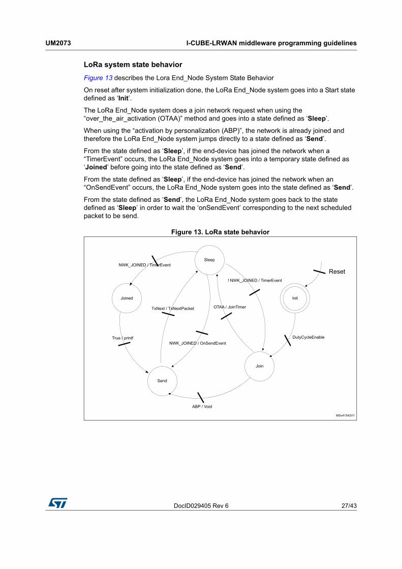
Figure 13 describes the Lora End_Node System State Behavior
On reset after system initialization done, the LoRa End_Node system goes into a Start state defined as ‘Init’.
The LoRa End_Node system does a join network request when using the “over_the_air_activation (OTAA)” method and goes into a state defined as ‘Sleep’.
When using the “activation by personalization (ABP)”, the network is already joined and therefore the LoRa End_Node system jumps directly to a state defined as ‘Send’.
From the state defined as ‘Sleep’, if the end-device has joined the network when a “TimerEvent” occurs, the LoRa End_Node system goes into a temporary state defined as ‘Joined’ before going into the state defined as ‘Send’.
From the state defined as ‘Sleep’, if the end-device has joined the network when an “OnSendEvent” occurs, the LoRa End_Node system goes into the state defined as ‘Send’.
From the state defined as ‘Send’, the LoRa End_Node system goes back to the state defined as ‘Sleep’ in order to wait the ‘onSendEvent’ corresponding to the next scheduled packet to be send.
Figure 13. LoRa state behavior

I-CUBE-LRWAN middleware programming guidelines UM2073
28/43 DocID029405 Rev 6
4.7.1 LoRa End_Node initialization
4.7.2 LoRa End_Node Join request entry point
4.7.3 LoRa End-Node start Tx
4.8 LIB End_Node application callbacks
4.8.1 Current battery level
Table 20 presents the current battery level function.
4.8.2 Current temperature level
4.8.3 Board unique ID
Table 22 presents the board unique ID function.
Table 17. LoRa class A initialization function
Function Description
void lora_Init (LoRaMainCallback_t *callbacks, LoRaParam_t* LoRaParamInit)
Initialization of the LoRa class A finite state machine
Table 18. LoRa End_Node Join request entry point
Function Description
void lora_Join (void)Join request to a network either in OTAA mode or ABP mode (The Join mode should be defined at compile time).
Table 19. LoRa End-Node start Tx
Function Description
void loraStartTx (TxEventType_t EventType)Start the OnTxTimerEvent occurence if EventType param is equal to TX_ON_TIMER. User is free to implement its own code here
Table 20. Current battery level function
Function Description
uint8_t HW_GetBatteryLevel (void) Get the battery level
Table 21. Current Temperature function
Function Description
uint16_t HW_GetTemperatureLevel (void)Get the current temperature (degree Celsius) of the chipset in q7.8 format

DocID029405 Rev 6 29/43
UM2073 I-CUBE-LRWAN middleware programming guidelines
42
4.8.4 Board random seed
Table 23 presents the board random seed function.
4.8.5 Make Rx frame
Table 24 presents the make Rx frame function.
4.8.6 Request Class mode switching
4.8.7 End_Node Class mode change confirmation
Table 22. Board unique ID function
Function Description
void HW_GetUniqueId (uint8_t *id) Get a unique Identifier
Table 23. Board random seed function
Function Description
uint32_t HW_GetRandomSeed (void) Get a random seed value
Table 24. Make Rx frame
Function Description
void LoraRxData (lora_AppData_t *AppData)To process the incoming frame application.
The user is free to implement his own code here
Table 25. LoRa has Joined function
Function Description
void LORA_HasJoined (void)Request to switch the LoRa class mode of the end-device (Class A or Class C)
Table 26. End_Node Class mode change confirmation function
Function Description
void LORA_ConfirmClass (DeviceClass_t Class)The end-device asserts his current class mode (Class A or Class C)

Example description UM2073
30/43 DocID029405 Rev 6
5 Example description
5.1 Single MCU end-device hardware description
The Application layer, the Mac Layer and the PHY driver are implemented on one MCU. The End_Node application is implementing this hardware solution (see Section 5.4)
The I-CUBE-LRWAN runs on several platforms such as:
• STM32 Nucleo platform stacked with a LoRa radio expansion board
• B-L072Z-LRWAN1 Discovery board (no LoRa expansion board required)
Optionally a ST X-NUCLEO-IKS01A1 sensor expansion board can be added on Nucleo and Discovery boards. The Nucleo-based supported hardware is presented in Table 27.
The I-CUBE-LRWAN Expansion Package can easily be tailored to any other supported device and development board.
The main characteristics of the LoRa radio expansion board are described in Table 28.
The radio interface is described below:
• The radio registers are accessed through the SPI
• Three interrupt lines are mandatory: DIO0, DIO1 and DIO2. The DIO3, DIO4 and DIO5 lines are not essential to run a LoRa link as only the DIO0, DIO1 and DIO2 are used in this application
• One GPIO from the MCU is used to reset the radio
• One MCU pin is used to control the antenna switch to set it either in Rx mode or in Tx mode.
Table 27. Nucleo-based supported hardware
LoRa radio expansion board / Nucleo board
SX1276MB1MAS SX1276MB1LAS SX1272MB2DAS
NUCLEO-L053R8 Supported Supported Supported
NUCLEO-L073RZ Supported SupportedSupported
(P-NUCLEO-LRWAN1(1))
1. This particular configuration is commercially available as a kit P-NUCLEO-LRWAN1.
NUCLEO-L152RE Supported Supported Supported
NUCLEO-L476RG Supported Supported Supported
Table 28. LoRa radio expansion boards characteristics
Board Characteristics
SX1276MB1MAS 868 MHz (HF) at 14 dBm and 433 MHz (LF) at 14 dBm
SX1276MB1LAS 915 MHz (HF) at 20 dBm and 433 MHz (LF) at 14 dBm
SX1272MB2DAS 915 MHz and 868 MHz at 14 dBm

DocID029405 Rev 6 31/43
UM2073 Example description
42
The hardware mapping is described in the hardware configuration files at:
• Projects\Multi\Applications\LoRa\classA\inc\platform_hw_conf.h for End_Node project
• Projects\Multi\Applications\LoRa\PingPong\inc\platform_hw_conf.h for PingPong project
At any of above locations, the platform can be either STM32L0xx, STM32L1xx, STM32L4xx or MLM32L0xx (Murata modem device).
Interrupts
Table 29 shows the interrupt priorities level applicable for the Cortex system processor exception and for the STM32L0 Series LoRa application-specific interrupt (IRQ).
5.2 Split end-device hardware description (two-MCUs solution)
The Application layer, the Mac Layer, and the PHY driver are separated. The LoRa End_Node is composed of a LoRa modem and a host controller. The LoRa modem is running the Lora stack (Mac Layer and the Phy Layer) and is controlled by a Lora host implementing the application layer.
The AT_Master application implementing the Lora host on a NUCLEO board, is compatible with the AT_Slave application (see Section 5.6). The AT_Slave application demonstrates a modem on the CMWX1ZZABZ-091 LoRa module (Murata). The AT_Master application is also compatible with the I-NUCLEO-LRWAN1 expansion board featuring the WM-SG-SM-42 LPWAN module from USI and with the LRWAN_NS1 expansion board featuring the RiSiNGHF modem RHF0M003 available in P-NUCLEO-LRWAN3 (see Section 5.7).
This split solution allows to design the application layer without any constraint linked to the real time requirement of LoRaWAN stack.
Figure 14. Concept for split end-device solution
Table 29. STM32L0xx IRQ priorities
Interrupt name Preempt priority Subpriority
RTC 0 NA
EXTI2_3 0 NA
EXTI4_15 0 NA

Example description UM2073
32/43 DocID029405 Rev 6
The interface between the LoRa modem and the LoRa host is a UART running AT commands.
5.3 Package description
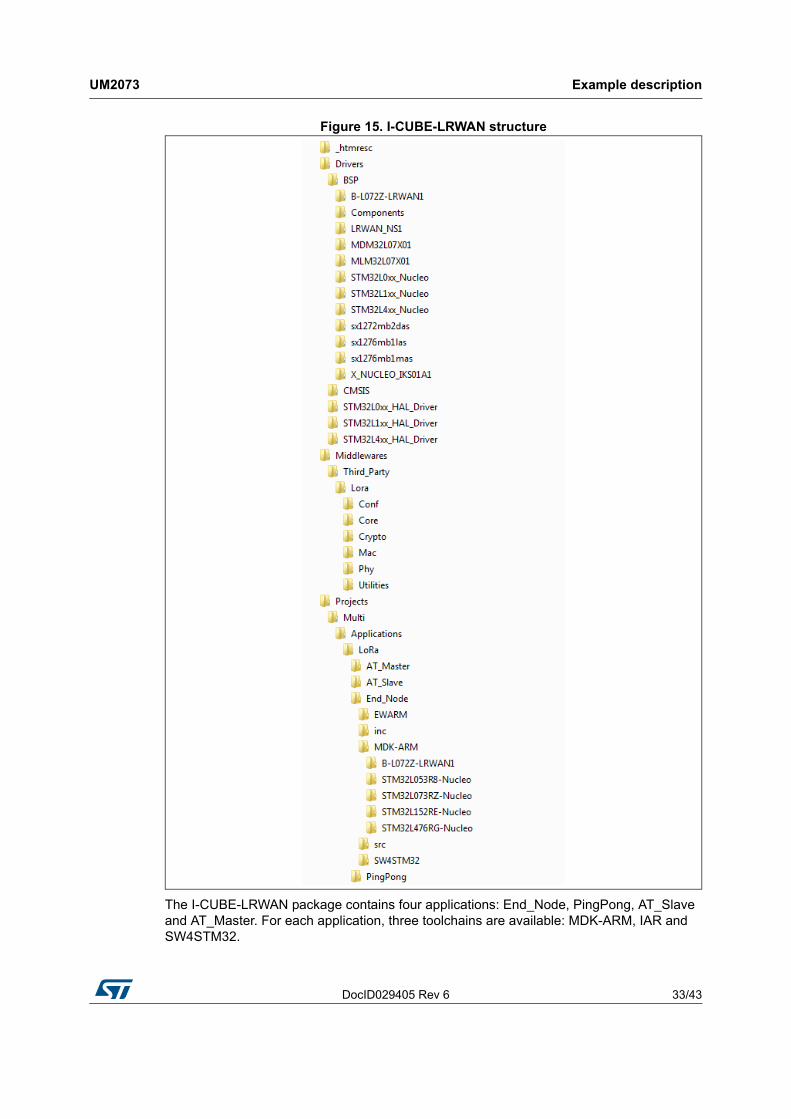
When the user unzips the I-CUBE-LRWAN, the package presents the structure shown in Figure 15.
DocID029405 Rev 6 33/43
UM2073 Example description
42
Figure 15. I-CUBE-LRWAN structure
The I-CUBE-LRWAN package contains four applications: End_Node, PingPong, AT_Slave and AT_Master. For each application, three toolchains are available: MDK-ARM, IAR and SW4STM32.

Example description UM2073
34/43 DocID029405 Rev 6
5.4 End_Node application
This application reads the temperature, humidity and atmospheric pressure from the sensors through the I2C. The MCU measures the supplied voltage through VREFLNT in order to calculate the battery level. These four data (temperature, humidity, atmospheric pressure and battery level) are sent periodically to the LoRa network using the LoRa radio in class A at 868 MHz.
In order to launch the LoRa End_Node project, the user should go to \Projects\Multi\Applications\LoRa\End_Node and choose his favorite toolchain folder (in the IDE environment). The user selects then the LoRa project from the proper target board.
5.4.1 Activation methods and keys
There are two ways to activate a device on the network, either by OTAA or by ABP.
The file \Projects\\Multi\Applications\LoRa\End_Node\commissioning.h gathers all the data related to the device activation. The chosen method, along with the commissioning data, are printed on the virtual port and visible on a terminal.
5.4.2 Debug switch
The user must go to \Projects\Multi\Applications\LoRa\End_Node\inc\hw_conf.h to enable the debug mode or/and the trace mode by commenting out #define DEBUG/ #define TRACE.
The debug mode enables the DBG_GPIO_SET and the DBG_GPIO_RST macros as well as the debugger mode even when the MCU goes in low-power. The trace mode enables the DBG_PRINTF macro.
Note: In order to enable a true low-power, both “#define” mentioned above must be commented out.
5.4.3 Sensor switch
When no sensor expansion board is plugged on the set-up, the #define SENSOR_ENBALED must be commented out on the \Projects\Multi\Applications\LoRa\End_Node\inc\hw_conf.h.
Table 30 provides a summary of the main options for the application configuration.

DocID029405 Rev 6 35/43
UM2073 Example description
42
Note: The maximum payload length allowed depends on both the region and the selected data rate, so the payload format must be carefully designed according to these parameters.
5.5 PingPong application description
This application is a simple Rx/Tx RF link between two LoRa end-devices. By default, each LoRa end-device starts as a master and transmits a ‘Ping’ message and wait for an answer. The first LoRa end-device receiving a ‘Ping’ message becomes a slave and answers the master with a ‘Pong’ message. The PingPong is then started.
In order to launch the PingPong project, the user must go to the ‘\Projects\Multi\Applications\LoRa\PingPong’ folder and follow the same procedure as for the LoRa End_Node project to launch the preferred toolchain.
Hardware and software set-up environment
To setup the STM32LXxx-NUCLEO, connect the NUCLEO (or the B-L072Z-LRWAN1) board to the computer with a USB cable type A to mini B to the ST-LINK connector (CN1). Ensure that the CN2 ST-LINK connector jumpers are fitted. See Figure 16 for a representation of the PingPong setup.
Table 30. Switch options for the application's configuration
Project Switch option Definition Location
LoRa stack
OVER_THE_AIR_ACTIVATIONApplication uses over-the- air activation procedure
Commissioning
STATIC_DEVICE_EUIStatic or dynamic end- device identification
Commissioning
STATIC_DEVICE_ADDRESSStatic or dynamic end- device address
Commissioning
REGION_EU868
Enable the EU band selection Compiler option setting
REGION_EU433
REGION_US915
REGION_AS923
REGION_AU915
REGION_CN470
REGION_CN779
REGION_IN865
REGION_KR920
Sensor
DEBUG Enable ‘Led on/off’ hw_conf.h
TRACE Enable ‘printf’. hw_conf.h
SENSOR_ENABLEDEnable the call to the sensor board
hw_conf.h

Example description UM2073
36/43 DocID029405 Rev 6
Figure 16. PingPong setup
5.6 AT_Slave application description
The purpose of this example is to implement a LoRa modem controlled though AT command interface over UART by an external host.
The external host can be a host-microcontroller embedding the application and the AT driver or simply a computer executing a terminal.
This application is targeting the B-L072Z-LRWAN1 Discovery board embedding the CMWX1ZZABZ-091 LoRa module. This application uses the Cube Low Layer drivers APIs targeting the STM32L072CZ to optimize the code size.
The AT_Slave example implements the Lora stack driving the built-in LoRa radio. The stack is controlled through AT command interface over UART. The modem is always in Stop mode unless it processes an AT command from the external host.
In order to launch the AT_Slave project, the user must go to the ‘\Projects\Multi\Applications\LoRa\AT_Slave’ folder and follow the same procedure as for the LoRa End_Node project to launch the preferred toolchain.
For more details, refer to the application note AN4967 which gives the list of AT commands and their description.
5.7 AT_Master application description
The purpose of this application is to read sensor data and to send them to a Lora Network through an external Lora Modem. The AT_Master application implements a complete set of AT commands to drive the LoRa stack which is embedded in the external LoRA modem.
External LoRA modem is targeting either the B-L072Z-LRWAN1 Discovery board or the I-NUCLEO-LRWAN1 board (based on the WM-SG-SM-42 USI module) or the LRWAN-NS1 expansion board featuring the RiSiNGHF® modem available in P-NUCLEO-LRWAN3.
This application uses the STM32Cube HAL drivers APIs targeting the STM32L0 Series.
For more details, refer to the application note AN4967 which gives the list of AT commands and their description.
BSP programming guidelines
Table 31 gives a description of the BSP (board support package) driver APIs to interface with the external LoRa module.

DocID029405 Rev 6 37/43
UM2073 Example description
42
Note: The NUCLEO board communicates with expansion board via UART (PA2,PA3). The following modifications shall be applied: (cf. chapter 5.8 of UM1724).
• SB62 and SB63 should be closed
• SB13 and SB14 should be opened to disconnect STM32 UART from STLINK
Table 31. BSP programming guidelines
Function Description
ATEerror_t Modem_IO_Init (void) Modem initialization
void Modem_IO_DeInit (void) Modem de-initialization
ATEerror_t Modem_AT_Cmd (ATGroup_t, at_group, ATCmd_t Cmd, void *pdata)
Modem IO commands
System performances UM2073
38/43 DocID029405 Rev 6
6 System performances
6.1 Memory footprints
The values in Table 32 have been measured for the following configuration of the Keil compiler (ARM compiler 5.05):
• Optimization: optimized for size level 3
• Debug option: off
• Trace option: off
• Target: P-NUCLEO-LRWAN1 (STM32L073+ SX1272MB2DAS)
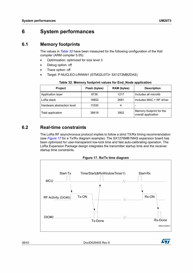
6.2 Real-time constraints
The LoRa RF asynchronous protocol implies to follow a strict TX/Rx timing recommendation (see Figure 17 for a Tx/Rx diagram example). The SX1276MB1MAS expansion board has been optimized for user-transparent low-lock time and fast auto-calibrating operation. The LoRa Expansion Package design integrates the transmitter startup time and the receiver startup time constraints.
Figure 17. Rx/Tx time diagram
Table 32. Memory footprint values for End_Node application
Project Flash (bytes) RAM (bytes) Description
Application layer 8736 1217 Includes all microlib
LoRa stack 18852 2681 Includes MAC + RF driver
Hardware abstraction level 11030 4 -
Total application 38618 3902Memory footprint for the overall application

DocID029405 Rev 6 39/43
UM2073 System performances
42
Rx window channel start
The Rx window opens the RECEIVE_DELAY1 for 1second (+/- 20 microseconds) or the JOIN_ACCEPT_DELAY1 for 5 seconds (+/- 20 microseconds) after the end of the uplink modulation.
The current scheduling interrupt-level priority has to be respected. In other words, all the new user-interrupts must have an interrupt priority > DI0#n interrupt (see Table 29) in order to avoid stalling the received startup time.
6.3 Power consumption
The power-consumption measurement has been established for the Nucleo boards associated to the SX1276MB1MAS shield.
Measurements setup:
• No DEBUG
• No TRACE
• No SENSOR_ENABLED
Measurements results:
• Typical consumption in stop mode: 1.3 µA
• Typical consumption in run mode: 8.0 mA
Measurements figures:
• Instantaneous consumption over 30 seconds
The Figure 17 shows an example of the current consumption against time on a microcontroller of the STM32L0 Series.

System performances UM2073
40/43 DocID029405 Rev 6
Figure 18. STM32L0 current consumption against time

DocID029405 Rev 6 41/43
UM2073 Revision history
42
7 Revision history
Table 33. Document revision history
Date Revision Changes
27-Jun-2016 1 Initial release.
10-Nov-2016 2
Updated:
– Introduction
– Section 2.1: Overview
– Section 3.2: Features
– Section 5: Example description
– Section 6: System performances
4-Jan-2017 3
Updated:
– Introduction with reference to the CMWX1ZZABZ-xxx LoRa module (Murata).
– Section 5.1: Hardware description: 3rd hardware configuration file added.
– Section 5.2: Package description: AT_Slave application added.
Added:
– Section 5.5: AT_Slave application description
21-Feb-2017 4
Updated:
– Introduction with I-NUCLEO-LRWAN1 LoRa expansion board.
– Figure 10: Project files structure
– Section 5.1: Single MCU end-device hardware description
– Figure 15: I-CUBE-LRWAN structure
– Section 5.4: End_Node application
– Section Table 27.: Switch options for the application's configuration
– Section 5.5: PingPong application description
– Section 5.6: AT_Slave application description
– Table 29: Memory footprint values for End_Node application
Added:
– Section 5.2: Split end-device hardware description (two-MCUs solution)
– Section 5.7Section 5.7: AT_Master application description.

Revision history UM2073
42/43 DocID029405 Rev 6
18-Jul-2017 5
Added:
– Note to Section 5.4: End_Node application on maximum payload length allowed
– Note to Section 5.7: AT_Master application description on the NUCLEO board communication with expansion board via UART
14-Dec-2017 6
Added:
– New modem reference: expansion board featuring the RiSiNGHF® modem RHF0M003
Updated:
– New architecture design (LoRa FSM removed)
– Figure 10: Project files structure
– Figure 12: Operation model
Table 33. Document revision history (continued)
Date Revision Changes

DocID029405 Rev 6 43/43
UM2073
43
IMPORTANT NOTICE – PLEASE READ CAREFULLY
STMicroelectronics NV and its subsidiaries (“ST”) reserve the right to make changes, corrections, enhancements, modifications, and improvements to ST products and/or to this document at any time without notice. Purchasers should obtain the latest relevant information on ST products before placing orders. ST products are sold pursuant to ST’s terms and conditions of sale in place at the time of order acknowledgement.
Purchasers are solely responsible for the choice, selection, and use of ST products and ST assumes no liability for application assistance or the design of Purchasers’ products.
No license, express or implied, to any intellectual property right is granted by ST herein.
Resale of ST products with provisions different from the information set forth herein shall void any warranty granted by ST for such product.
ST and the ST logo are trademarks of ST. All other product or service names are the property of their respective owners.
Information in this document supersedes and replaces information previously supplied in any prior versions of this document.
© 2017 STMicroelectronics – All rights reserved