Embed Size (px)
Citation preview
1.00 (Sep’09) 1
USER'S MANUAL
Hurricane 5004N
Wireless-N (2T2R) 4-Port ADSL2+
Modem/Router
Version 1.0 (Jan’10)
PROLiNK® H5004N User Manual www.prolink2u.com
Version 1.00 (Jan’10) i
TABLE OF CONTENTS
Chapter 1 Introduction 2 1.1 Intended Audience 2 1.2 Definitions of Terms Used In This Document 2 1.3 Acronyms Used Throughout This Document 2 1.4 Usage Instructions 2 1.5 Questions or Comments on this Document 2 Chapter 2 System Overview 3 2.1 General Description 3 2.2 Specifications 3 Chapter 3 Hardware Installation 6 3.1 Hardware Requirements 6 3.2 LED Status Description 6 3.3 Hardware Setup Procedures 7 Chapter 4 Software Configuration 8 4.1 LAN Configuration 10 4.2 Wireless Configuration 11 4.3 WAN Configuration 19 4.4 Services Configuration 23 4.5 Advance Configuration 39 4.6 Diagnostic 48 4.7 Admin 49 4.8 Statistics 55 Chapter 5 Channel Mode Configuration 57 5.1 Bridge Mode 57 5.2 MER (Mac Encapsulating Routing) Mode 58 5.3 PPPoE Mode 59 5.4 PPPoA Mode 60 5.5 1483 Routed Mode 61 Chapter 6 Protocol Stacks 62 6.1 1483 Bridged Model 62 6.2 1483 MER Model 62 6.3 PPPoE Model 63 6.4 PPPoA Model 63 6.5 1483 Routed Model 64 Chapter 7 Questions & Answers 65 Chapter 8 Technical Support 66
PROLiNK® H5004N User Manual www.prolink2u.com
Version 1.00 (Jan’10) 2
Chapter 1
Introduction
The Wireless-N (2T2R) 4-Port ADSL2+ Modem/Router user manual contains the guidance to install and
configure PROLiNK Hurricane 5004N Wireless-N (2T2R) 4-Port ADSL2+ Modem/Router using the Web
GUI.
1.1 Intended Audience
This manual is intended for end users to access ADSL broadband service.
1.2 Definitions of Terms Used In This Document
None.
1.3 Acronyms Used Throughout This Document
None.
1.4 Usage Instructions
None.
1.5 Questions or Comments on this Document
Please contact us and visit our website at http://www.prolink2u.com should you have any questions
or comments on this document.
PROLiNK® H5004N User Manual www.prolink2u.com
Version 1.00 (Jan’10) 3
Chapter 2
System Overview
2.1 General Description
Hurricane 5004N wireless router is a high-speed Wireless-N (2T2R) 4-Port ADSL2+
Modem/Router that is specifically designed to connect to the Internet and to directly connect to
your local area network (LAN) via high-speed 10/100 Mbps Ethernet, or wireless LAN (WLAN).
The ADSL2+ modem is compatible with the latest ADSL standards, including ADSL2 and
ADSL2+, and supports up to 26 Mbps downstream and 3 Mbps upstream to deliver true
broadband speed and throughput. The DSL router supports wireless 802.11b/g/n and the
following security protocols: WEP, WPA, WPA2, and 802.1x.
To ensure fully compatibility, the DSL device was tested with all major DSLAMs, and support
standard 10/100 Mbps Base-T Ethernet interface Auto MDI/MDIx 10/100 Switch function allowing
user easily to link to PC or other Switches/Hubs. The DSL device is an idea solution for multi-
users utilizing build-in channel mode (PPPoE/A, IPoA, IPoE), IP routing, NAT functionalities
sharing the ADSL link. The DSL device is also a perfect solution for the residential users, it
supports the users with bridge mode in host based PPPoE Client.
2.2 Specifications 2.2.1 ADSL compliance
- ANSI T1.413 Issue2
- ITU-T G.992.1 (G.dmt)
- ITU-T G.992.2 (G.lite)
- ITU-T G.994.1 (G.hs)
- ITU-T G.992.3 ADSL2 G.dmt.bit
- ITU-T G.992.4 ADSL2 G.lite.bis
- ITU-T G.992.5 ADSL+
- Auto-negotiating rate adaptation
- Annex A(ADSL over POTS) , Annex L(ReADSL) and Annex M
- Maximum downstream rate of 26 Mbps
- Maximum upstream rate of 3Mbps
- Supports Dying Gasp (Optional)
2.2.2 WLAN features
- Complies with IEEE 802.11b/g/n standards
- Backward compatible with 802.11b/g devices while operating at 802.11n data rate
- 2x2 MIMO technology for extended reception robustness and exceptional throughput
PROLiNK® H5004N User Manual www.prolink2u.com
Version 1.00 (Jan’10) 4
- 802.11b/g Data rates : 1, 2, 5.5, 6, 9, 11, 12, 18, 24, 36, 48, and 54Mbps, 802.11n maximum
Data rates :150Mbps receive/transmit PHY rate using 20MHz bandwidth, 300Mbps
receive/transmit PHY rate using 40MHz bandwidth
- Burst-mode support for dramatically enhanced throughput
- DSSS with DBPSK and DQPSK, CCK modulations and demodulations supported with rate
compatible punctured convolution coding with coding rate of 1/2, 2/3, 3/4 and 5/6
- OFDM with BPSK, QPSK, 16QAM and 64QAM modulations and demodulations supported with
long and short preamble
- Complies with WMM, 802.11e, and CCX specifications
- Complies with 802.11h, 802.11i, 802.11j specifications
- Hardware-based IEEE 802.11i encryption/decryption engine, including 64-bit/128-bit WEP,
TKIP, and AES
- Supports Wi-Fi alliance WPA and WPA2 security
2.2.3 Software features
- RFC-1483/2684 LLC/VC-Mux bridged/routed mode
- RFC-1577 Classical IP over ATM
- RFC-2516 PPPoE
- RFC-2364 PPPoA
- RFC-1661 PPP
- Bridge/Routing
o DHCP Client/Sever/Relay
o IP routing : RIP v1/v2
o Static route
o DNS Relay Agent
o Dynamic DNS
o IGMP Proxy
o 802.1d Spanning-Tree Protocol
o NAT (Network Address Translation)
o NAPT port forwarding
o DMZ support
- Security
o User authentication for PPP
o PAP (Password Authentication Protocol)
o CHAP (Challenge Authentication Protocol)
PROLiNK® H5004N User Manual www.prolink2u.com
Version 1.00 (Jan’10) 5
- Firewall
o IP/Port filtering
o MAC filtering
- ATM
o ITU-T 1.610 F4/F5 OAM send and receiver loop-back
o ATM QoS : CBR, rt-VBR, nrt-VBR and UBR
o Multiple PVC : support 8 PVCs
2.2.4 Management
- Web-based configuration
- Telnet remote management
- SNMP v1/v2/Trap
- Diagnostic tool
- Firmware upgrade through FTP, TFTP and HTTP
- UPnP support
- ACL (Access Control List)
PROLiNK® H5004N User Manual www.prolink2u.com
Version 1.00 (Jan’10) 6
Chapter 3
Hardware Installation
3.1 Hardware Requirements
3.1.1 10V Power Adapter
3.1.2 RJ-45 Ethernet cable
3.1.3 RJ-11 ADSL line
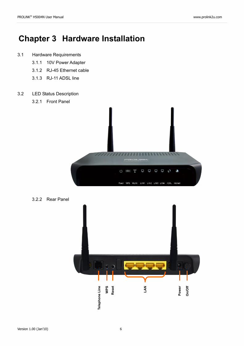
3.2 LED Status Description
3.2.1 Front Panel
3.2.2 Rear Panel
Tele
phon
e Li
ne
WPS
Res
et
LAN
Po
wer
O
n/O
f f

PROLiNK® H5004N User Manual www.prolink2u.com
Version 1.00 (Jan’10) 7
3.3 Hardware Setup Procedures
3.3.1 Connect RJ-11 line from Hurricane 5004N to the wall phone socket
3.3.2 Connect RJ-45 line from your PC LAN Port to Hurricane 5004N Ethernet port
3.3.3 Connect the 10V power adapter
PROLiNK® H5004N User Manual www.prolink2u.com
Version 1.00 (Jan’10) 8
Chapter 4
Software Configuration
The DSL device is an ADSL2+ wireless router. When you power on the device, the system will boot up
and connect to ADSL automatically. The system provides a PVC for bridge test by default. The default
configurations for the system are listed below.
LAN IP address: 192.168.1.1, Netmask: 255.255.255.0
UART setting: 115200bps, 8 bits, no parity, 1 stop bit, no flow control.
VPI/VCI for ATM: 0/35
ADSL Line mode: Auto-detect.
User can change settings via WEB browser. The following sections describe the set up procedures.
Please set your PC’s Ethernet port as follow:
IP address: 192.168.1.XXX (e.g. 192.168.1.10)
Netmask: 255.255.255.0
Access the Web Console:
Start your web browser.
Type the Ethernet IP address of the modem/router on the address bar of the browser. Default
IP address is 192.168.1.1.
The Enter Network Password dialog box appears. Default Username: admin Password:
password
PROLiNK® H5004N User Manual www.prolink2u.com
Version 1.00 (Jan’10) 9
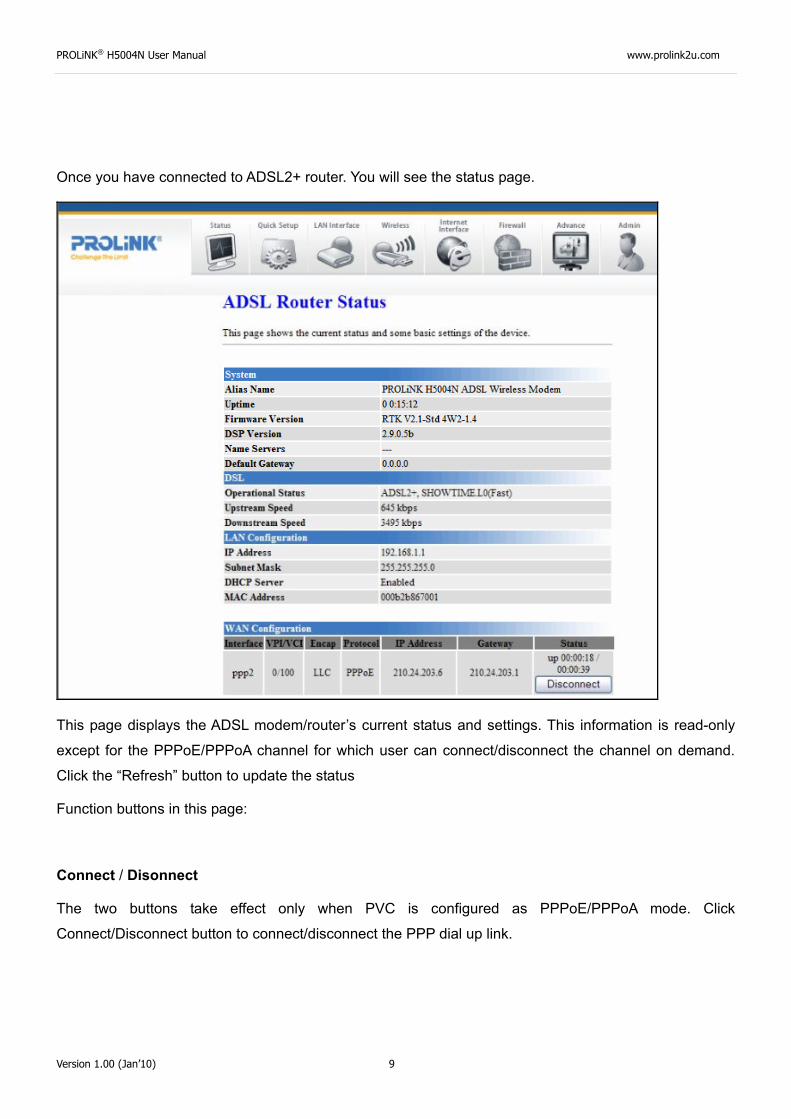
Once you have connected to ADSL2+ router. You will see the status page.
This page displays the ADSL modem/router’s current status and settings. This information is read-only
except for the PPPoE/PPPoA channel for which user can connect/disconnect the channel on demand.
Click the “Refresh” button to update the status
Function buttons in this page:
Connect / Disonnect
The two buttons take effect only when PVC is configured as PPPoE/PPPoA mode. Click
Connect/Disconnect button to connect/disconnect the PPP dial up link.
PROLiNK® H5004N User Manual www.prolink2u.com
Version 1.00 (Jan’10) 10
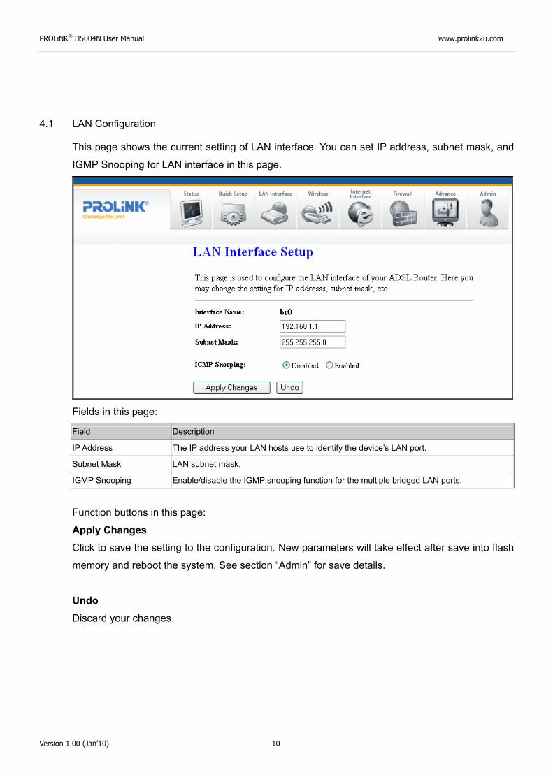
4.1 LAN Configuration
This page shows the current setting of LAN interface. You can set IP address, subnet mask, and
IGMP Snooping for LAN interface in this page.
Fields in this page:
Field Description
IP Address The IP address your LAN hosts use to identify the device’s LAN port.
Subnet Mask LAN subnet mask.
IGMP Snooping Enable/disable the IGMP snooping function for the multiple bridged LAN ports.
Function buttons in this page:
Apply Changes Click to save the setting to the configuration. New parameters will take effect after save into flash
memory and reboot the system. See section “Admin” for save details.
Undo Discard your changes.
PROLiNK® H5004N User Manual www.prolink2u.com
Version 1.00 (Jan’10) 11
4.2 Wireless Configuration
This section provides the wireless network settings for your WLAN interface. The wireless
interface enables the wireless AP function for ADSL modem.
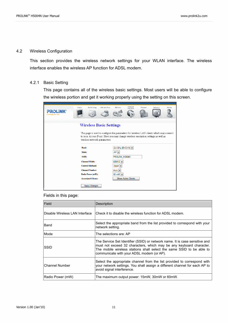
4.2.1 Basic Setting
This page contains all of the wireless basic settings. Most users will be able to configure
the wireless portion and get it working properly using the setting on this screen.
Fields in this page:
Field Description
Disable Wireless LAN Interface Check it to disable the wireless function for ADSL modem.
Band Select the appropriate band from the list provided to correspond with your network setting.
Mode The selections are: AP
SSID
The Service Set Identifier (SSID) or network name. It is case sensitive and must not exceed 32 characters, which may be any keyboard character. The mobile wireless stations shall select the same SSID to be able to communicate with your ADSL modem (or AP).
Channel Number Select the appropriate channel from the list provided to correspond with your network settings. You shall assign a different channel for each AP to avoid signal interference.
Radio Power (mW) The maximum output power: 15mW, 30mW or 60mW.
PROLiNK® H5004N User Manual www.prolink2u.com
Version 1.00 (Jan’10) 12
Function buttons in this page:
Associated Clients Click it will show the clients currently associated with the ADSL modem.
Apply Changes Change the settings. New parameters will take effect after save into flash memory and
reboot the system. See section “Admin” for save details.
Reset Discard your changes and reload all settings from flash memory.
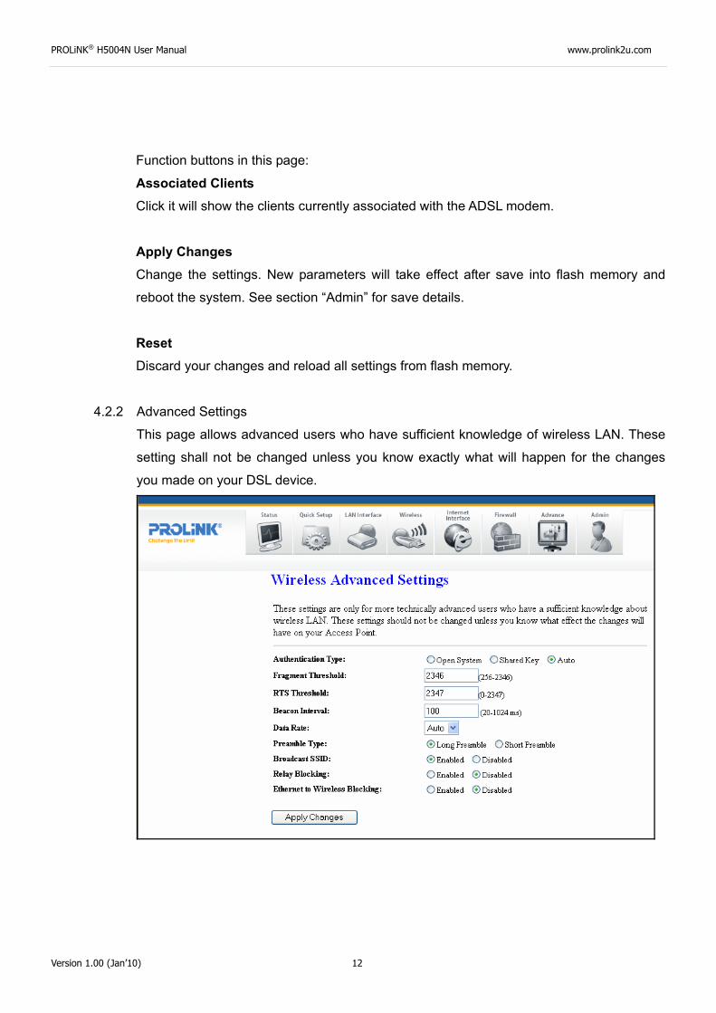
4.2.2 Advanced Settings
This page allows advanced users who have sufficient knowledge of wireless LAN. These
setting shall not be changed unless you know exactly what will happen for the changes
you made on your DSL device.
PROLiNK® H5004N User Manual www.prolink2u.com
Version 1.00 (Jan’10) 13
Fields in this page:
Field Description
Authentication Type
• Open System: Open System authentication is not required to be successful while a client may decline to authenticate with any particular other client.
• Shared Key: Shared Key is only available if the WEP option is implemented. Shared Key authentication supports authentication of clients as either a member of those who know a shared secret key or a member of those who do not. IEEE 802.11 Shared Key authentication accomplishes this without the need to transmit the secret key in clear. Requiring the use of the WEP privacy mechanism.
• Auto: Auto is the default authentication algorithm. It will change its authentication type automatically to fulfill client’s requirement.
Fragment Threshold
This value should remain at its default setting of 2346. It specifies the maximum size for a packet before data is fragmented into multiple packets. If you experience a high packet error rate, you may slightly increases the “Fragment Threshold” value within the value range of 256 to 2346. Setting this value too low may result in poor network performance. Only minor modifications of this value are recommended.
RTS Threshold
This value should remain at its default setting of 2347. Should you encounter inconsistent data flow, only minor modifications are recommended. If a network packet is smaller than the preset “RTS threshold” size, the RTS/CTS mechanism will not be enabled. The ADSL modem (or AP) sends Request to Send (RTS) frames to a particular receiving station and negotiates the sending of a data frame. After receiving an RTS, the wireless station responds with a Clear to Send (CTS) frame to acknowledge the right to begin transmission.
Beacon Interval The Beacon Interval value indicates the frequency interval of the beacon. Enter a value between 20 and 1024. A beacon is a packet broadcast by the ADSL modem (or AP) to synchronize the wireless network. The default is 100.
Data Rate
The rate of data transmission should be set depending on the speed of your wireless network. You should select from a range of transmission speeds, or you can select Auto to have the ADSL modem (or AP) automatically use the fastest possible data rate and enable the Auto-Fallback feature. Auto-Fallback will negotiate the best possible connection speed between the AP and a wireless client. The default setting is Auto.
Preamble Type
The Preamble Type defines the length of the CRC (Cyclic Redundancy Check) block for communication between the AP and mobile wireless stations. Make sure to select the appropriate preamble type. Note that high network traffic areas should use the short preamble type. CRC is a common technique for detecting data transmission errors.
Broadcast SSID
If this option is enabled, the device will automatically transmit their network name (SSID) into open air at regular interval. This feature is intended to allow clients to dynamically discover and roam between WLANs; if this option is disabled, the device will hide its SSID. When this is done, the station cannot directly discover its WLAN and MUST be configure with the SSID. Note that in a home Wi-Fi network, roaming is largely unnecessary and the SSID broadcast feature serves no useful purpose. You should disable this feature to improve the security of your WLAN.
Relay Blocking When Relay Blocking is enabled, wireless clients will not be able to directly access other wireless clients.
Ethernet to Wireless Blocking
When enabled, traffic between Ethernet and wireless interfaces are not allowed.
PROLiNK® H5004N User Manual www.prolink2u.com
Version 1.00 (Jan’10) 14
Function buttons in this page:
Apply Changes Change the settings. New parameters will take effect after save into flash memory and
reboot the system. See section “Admin” for save details.
Reset Discard your changes and reload all settings from flash memory.
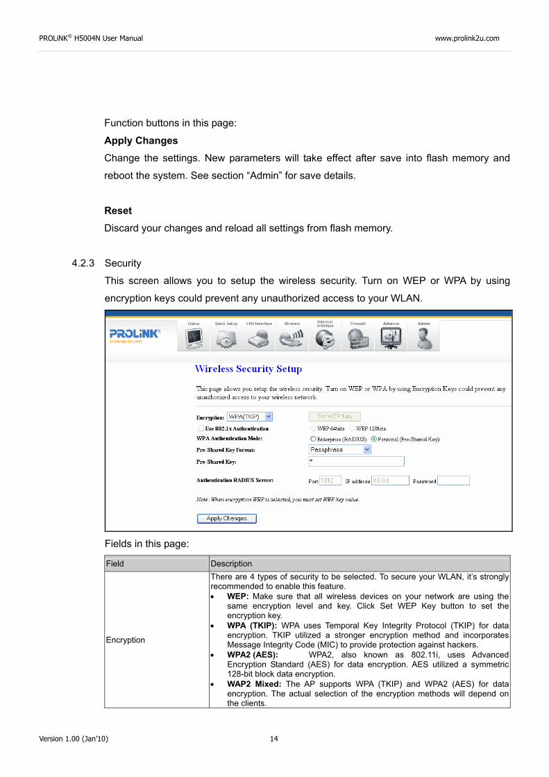
4.2.3 Security
This screen allows you to setup the wireless security. Turn on WEP or WPA by using
encryption keys could prevent any unauthorized access to your WLAN.
Fields in this page:
Field Description
Encryption
There are 4 types of security to be selected. To secure your WLAN, it’s strongly recommended to enable this feature. • WEP: Make sure that all wireless devices on your network are using the
same encryption level and key. Click Set WEP Key button to set the encryption key.
• WPA (TKIP): WPA uses Temporal Key Integrity Protocol (TKIP) for data encryption. TKIP utilized a stronger encryption method and incorporates Message Integrity Code (MIC) to provide protection against hackers.
• WPA2 (AES): WPA2, also known as 802.11i, uses Advanced Encryption Standard (AES) for data encryption. AES utilized a symmetric 128-bit block data encryption.
• WAP2 Mixed: The AP supports WPA (TKIP) and WPA2 (AES) for data encryption. The actual selection of the encryption methods will depend on the clients.
PROLiNK® H5004N User Manual www.prolink2u.com
Version 1.00 (Jan’10) 15
Use 802.1x Authentication
Check it to enable 802.1x authentication. This option is selectable only when the “Encryption” is choose to either None or WEP. If the “Encryption” is WEP, you need to further select the WEP key length to be either WEP 64bits or WEP 128bits.
WPA Authentication Mode
There are 2 types of authentication mode for WPA. • WPA-RADIUS: WPA RADIUS uses an external RADIUS server to perform
user authentication. To use WPA RADIUS, enter the IP address of the RADIUS server, the RADIUS port (default is 1812) and the shared secret from the RADIUS server. Please refer to “Authentication RADIUS Server” setting below for RADIUS setting. The WPA algorithm is selected between TKIP and AES, please refer to “WPA cipher Suite” below.
• Pre-Shared Key: Pre-Shared Key authentication is based on a shared secret that is known only by the parties involved. To use WPA Pre-Shared Key, select key format and enter a password in the “Pre-Shared Key Format” and “Pre-Shared Key” setting respectively. Please refer to “Pre-Shared Key Format” and “Pre-Shared Key” setting below.
Pre-Shared Key Format
• PassPhrase: Select this to enter the Pre-Shared Key secret as user-friendly textual secret.
• Hex (64 characters): Select this to enter the Pre-Shared Key secret as hexadecimal secret.
Pre-Shared Key
Specify the shared secret used by this Pre-Shared Key. If the “Pre-Shared Key Format” is specified as PassPhrase, then it indicates a passphrase of 8 to 63 bytes long; or if the “Pre-Shared Key Format” is specified as PassPhrase, then it indicates a 64-hexadecimal number.
Authentication RADIUS Server
If the WPA-RADIUS is selected at “WPA Authentication Mode”, the port (default is 1812), IP address and password of external RADIUS server are specified here.
Function buttons in this page:
Apply Changes Change the settings. New parameters will take effect after save into flash memory and
reboot the system. See section “Admin” for save details.
PROLiNK® H5004N User Manual www.prolink2u.com
Version 1.00 (Jan’10) 16
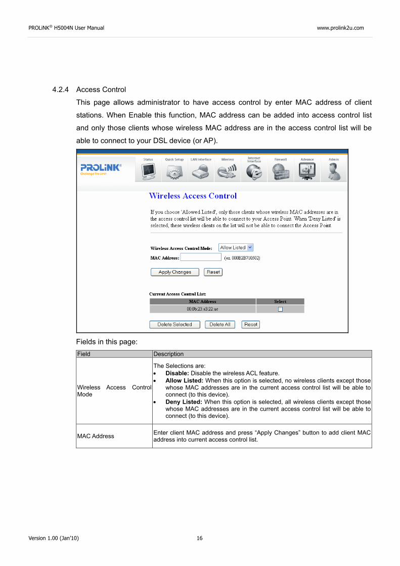
4.2.4 Access Control
This page allows administrator to have access control by enter MAC address of client
stations. When Enable this function, MAC address can be added into access control list
and only those clients whose wireless MAC address are in the access control list will be
able to connect to your DSL device (or AP).
Fields in this page: Field Description
Wireless Access Control Mode
The Selections are: • Disable: Disable the wireless ACL feature. • Allow Listed: When this option is selected, no wireless clients except those
whose MAC addresses are in the current access control list will be able to connect (to this device).
• Deny Listed: When this option is selected, all wireless clients except those whose MAC addresses are in the current access control list will be able to connect (to this device).
MAC Address Enter client MAC address and press “Apply Changes” button to add client MAC address into current access control list.
PROLiNK® H5004N User Manual www.prolink2u.com
Version 1.00 (Jan’10) 17
Function buttons for the setting block:
Apply Changes Click to add this entry into the Current Access Control List.
The Current Access Control List lists the client MAC addresses. Any wireless client with its
MAC address listed in this access control list will be able to connect to the device. You can
select the entries at the Select column and apply to the following function buttons.
Function buttons for the Current Access Control List:
Delete Selected Delete the selected entries from the list.
Delete All Flush the list.
4.2.5 WPS
Although home Wi-Fi networks have become more and more popular, users still have
trouble with the initial set up of network. This obstacle forces users to use the open
security and increases the risk of eavesdropping. Therefore, The Wi-Fi Protected Setup
(WPS) is designed to ease set up of security-enabled Wi-Fi networks and subsequently
network management.
The largest difference between WPS-enabled devices and legacy devices is that users do
not need the knowledge about SSID, channel and security settings, but they could still surf
in a security-enabled Wi-Fi network.
This device supports Push Button method and PIN method for WPS. The following sub-
paragraphs will describe the function of each item. The webpage is as below.
PROLiNK® H5004N User Manual www.prolink2u.com
Version 1.00 (Jan’10) 18
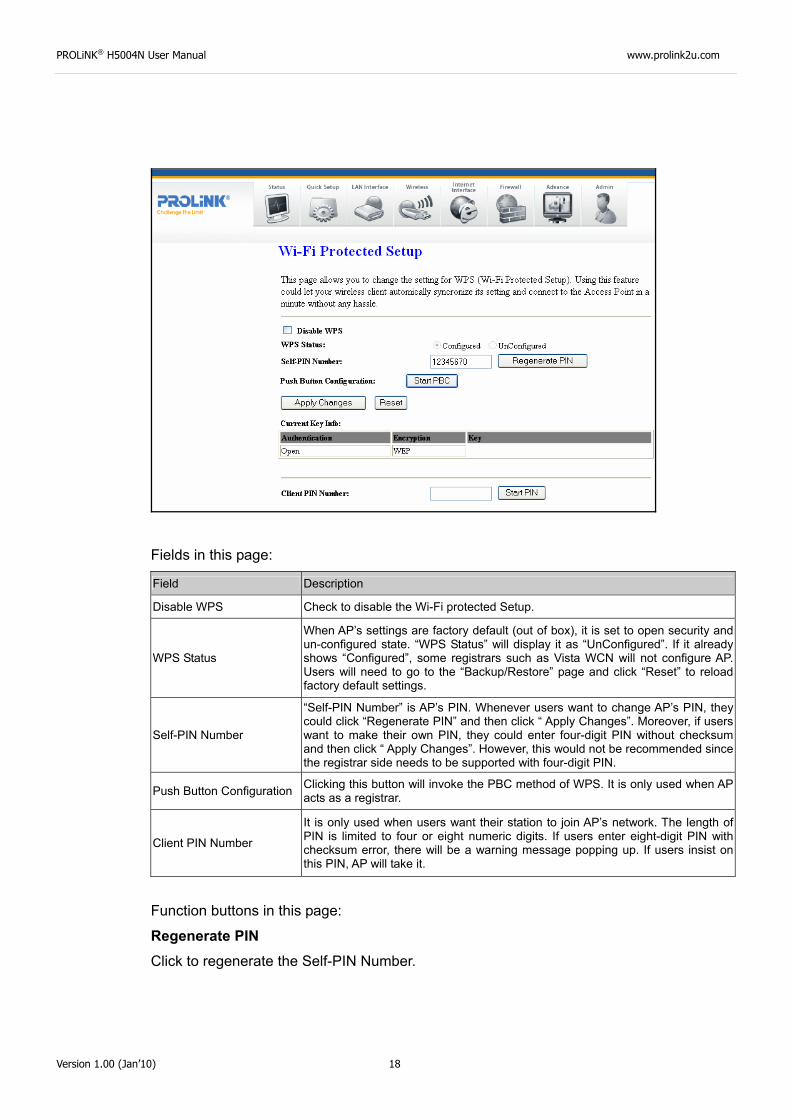
Fields in this page:
Field Description
Disable WPS Check to disable the Wi-Fi protected Setup.
WPS Status
When AP’s settings are factory default (out of box), it is set to open security and un-configured state. “WPS Status” will display it as “UnConfigured”. If it already shows “Configured”, some registrars such as Vista WCN will not configure AP. Users will need to go to the “Backup/Restore” page and click “Reset” to reload factory default settings.
Self-PIN Number
“Self-PIN Number” is AP’s PIN. Whenever users want to change AP’s PIN, they could click “Regenerate PIN” and then click “ Apply Changes”. Moreover, if users want to make their own PIN, they could enter four-digit PIN without checksum and then click “ Apply Changes”. However, this would not be recommended since the registrar side needs to be supported with four-digit PIN.
Push Button Configuration Clicking this button will invoke the PBC method of WPS. It is only used when AP acts as a registrar.
Client PIN Number
It is only used when users want their station to join AP’s network. The length of PIN is limited to four or eight numeric digits. If users enter eight-digit PIN with checksum error, there will be a warning message popping up. If users insist on this PIN, AP will take it.
Function buttons in this page:
Regenerate PIN Click to regenerate the Self-PIN Number.
PROLiNK® H5004N User Manual www.prolink2u.com
Version 1.00 (Jan’10) 19
Start PBC Click to start the Push Button method of WPS.
Apply Changes Click to commit changes.
Reset It restores the original values.
Start PIN Click to start the PIN method of WPS.
4.3 WAN Configuration
There are three sub-menu for WAN configuration: [Channel Config], [ATM Settings], and [ADSL
Settings].
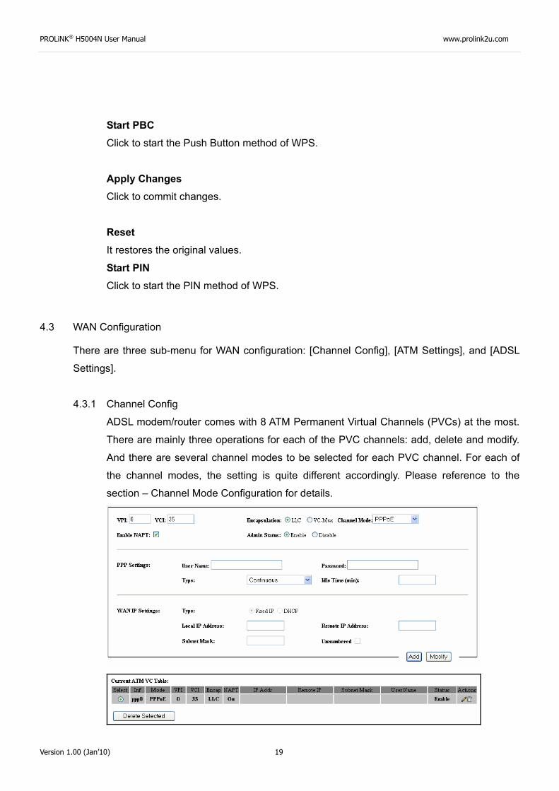
4.3.1 Channel Config
ADSL modem/router comes with 8 ATM Permanent Virtual Channels (PVCs) at the most.
There are mainly three operations for each of the PVC channels: add, delete and modify.
And there are several channel modes to be selected for each PVC channel. For each of
the channel modes, the setting is quite different accordingly. Please reference to the
section – Channel Mode Configuration for details.
PROLiNK® H5004N User Manual www.prolink2u.com
Version 1.00 (Jan’10) 20
Function buttons in this page:
Add Click Add to complete the channel setup and add this PVC channel into configuration.
Modify Select an existing PVC channel by clicking the radio button at the Select column of the
Current ATM VC Table before we can modify the PVC channel. After selecting an PVC
channel, we can modify the channel configuration at this page. Click Modify to complete
the channel modification and apply to the configuration.
Delete Select an existing PVC channel to be deleted by clicking the radio button at the Select
column of the Current ATM VC Table. Click Delete to delete this PVC channel from
configuration.
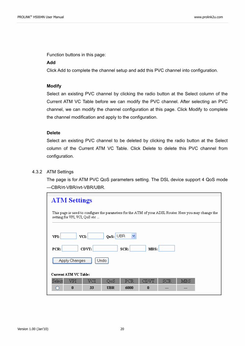
4.3.2 ATM Settings
The page is for ATM PVC QoS parameters setting. The DSL device support 4 QoS mode
—CBR/rt-VBR/nrt-VBR/UBR.
PROLiNK® H5004N User Manual www.prolink2u.com
Version 1.00 (Jan’10) 21
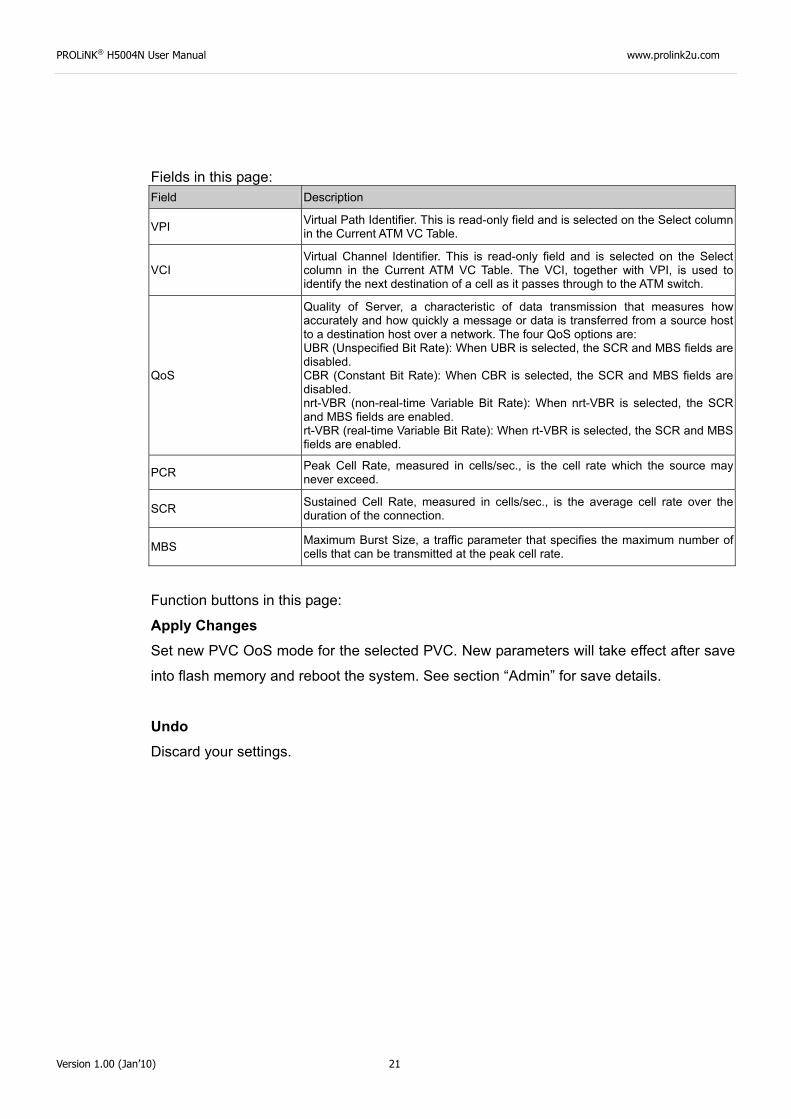
Fields in this page: Field Description
VPI Virtual Path Identifier. This is read-only field and is selected on the Select column in the Current ATM VC Table.
VCI Virtual Channel Identifier. This is read-only field and is selected on the Select column in the Current ATM VC Table. The VCI, together with VPI, is used to identify the next destination of a cell as it passes through to the ATM switch.
QoS
Quality of Server, a characteristic of data transmission that measures how accurately and how quickly a message or data is transferred from a source host to a destination host over a network. The four QoS options are: UBR (Unspecified Bit Rate): When UBR is selected, the SCR and MBS fields are disabled. CBR (Constant Bit Rate): When CBR is selected, the SCR and MBS fields are disabled. nrt-VBR (non-real-time Variable Bit Rate): When nrt-VBR is selected, the SCR and MBS fields are enabled. rt-VBR (real-time Variable Bit Rate): When rt-VBR is selected, the SCR and MBS fields are enabled.
PCR Peak Cell Rate, measured in cells/sec., is the cell rate which the source may never exceed.
SCR Sustained Cell Rate, measured in cells/sec., is the average cell rate over the duration of the connection.
MBS Maximum Burst Size, a traffic parameter that specifies the maximum number of cells that can be transmitted at the peak cell rate.
Function buttons in this page:
Apply Changes Set new PVC OoS mode for the selected PVC. New parameters will take effect after save
into flash memory and reboot the system. See section “Admin” for save details.
Undo Discard your settings.
PROLiNK® H5004N User Manual www.prolink2u.com
Version 1.00 (Jan’10) 22
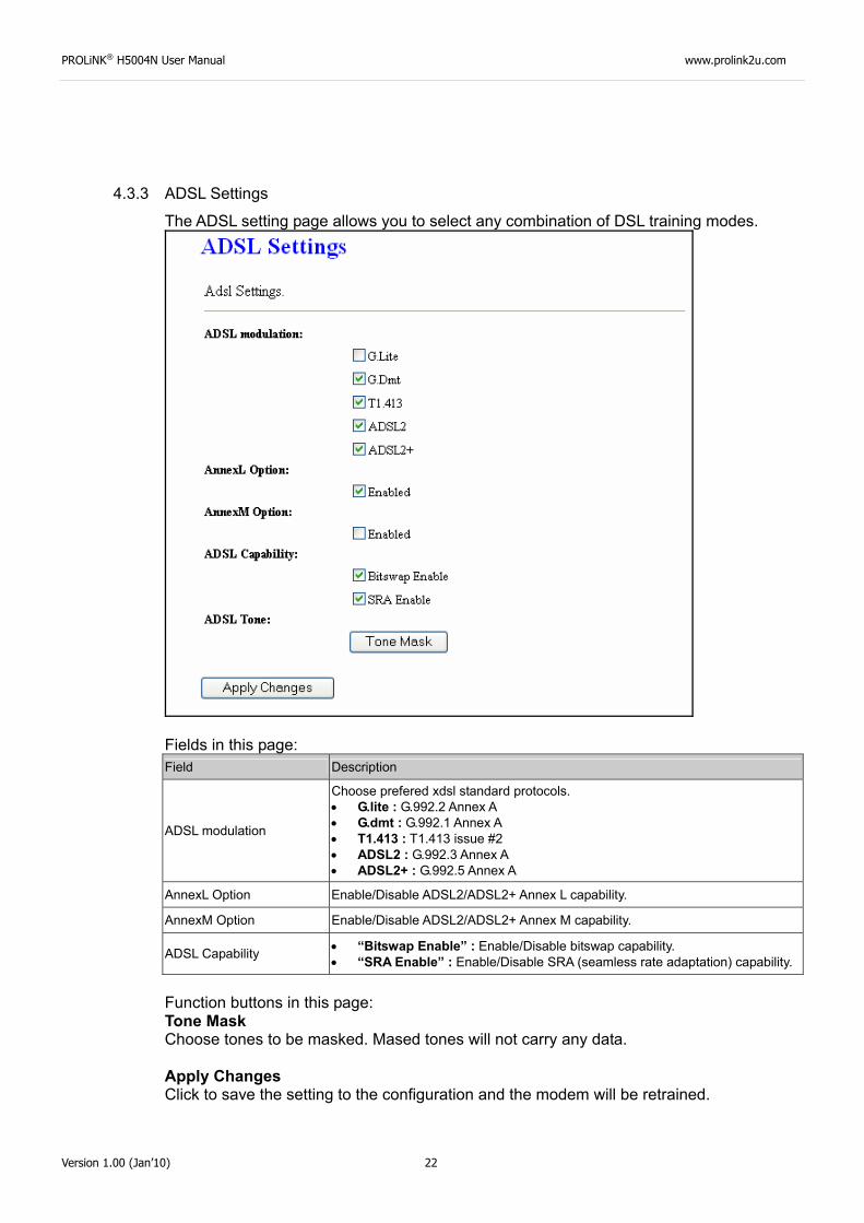
4.3.3 ADSL Settings
The ADSL setting page allows you to select any combination of DSL training modes.
Fields in this page: Field Description
ADSL modulation
Choose prefered xdsl standard protocols. • G.lite : G.992.2 Annex A • G.dmt : G.992.1 Annex A • T1.413 : T1.413 issue #2 • ADSL2 : G.992.3 Annex A • ADSL2+ : G.992.5 Annex A
AnnexL Option Enable/Disable ADSL2/ADSL2+ Annex L capability.
AnnexM Option Enable/Disable ADSL2/ADSL2+ Annex M capability.
ADSL Capability • “Bitswap Enable” : Enable/Disable bitswap capability. • “SRA Enable” : Enable/Disable SRA (seamless rate adaptation) capability.
Function buttons in this page: Tone Mask Choose tones to be masked. Mased tones will not carry any data. Apply Changes Click to save the setting to the configuration and the modem will be retrained.
PROLiNK® H5004N User Manual www.prolink2u.com
Version 1.00 (Jan’10) 23
4.4 Services Configuration
4.4.1 DHCP Mode
You can configure your network and DSL device to use the Dynamic Host Configuration
Protocol (DHCP). This page provides DHCP instructions for implementing it on your
network by selecting the role of DHCP protocol that this device wants to play. There are
two different DHCP roles that this device can act as: DHCP Serve and DHCP Relay.
When acting as DHCP server, you can setup the server parameters at the DHCP Server
page; while acting as DHCP Relay, you can setup the relay at the DHCP Relay page.
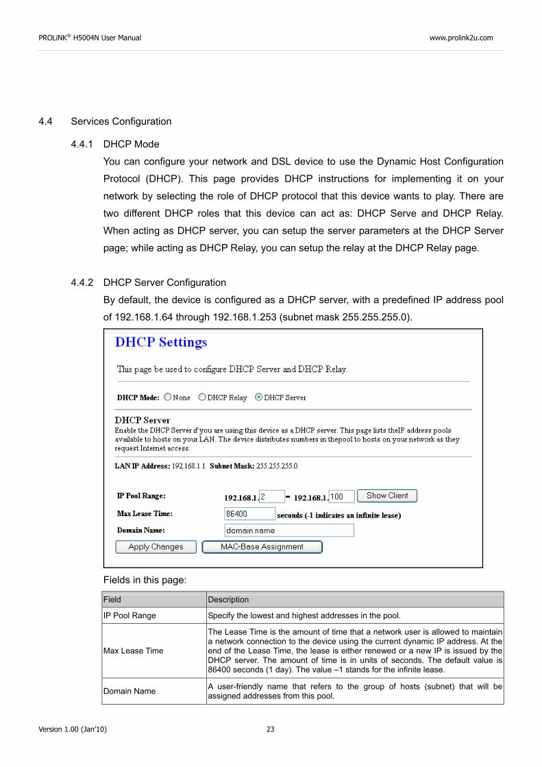
4.4.2 DHCP Server Configuration
By default, the device is configured as a DHCP server, with a predefined IP address pool
of 192.168.1.64 through 192.168.1.253 (subnet mask 255.255.255.0).
Fields in this page:
Field Description
IP Pool Range Specify the lowest and highest addresses in the pool.
Max Lease Time
The Lease Time is the amount of time that a network user is allowed to maintain a network connection to the device using the current dynamic IP address. At the end of the Lease Time, the lease is either renewed or a new IP is issued by the DHCP server. The amount of time is in units of seconds. The default value is 86400 seconds (1 day). The value –1 stands for the infinite lease.
Domain Name A user-friendly name that refers to the group of hosts (subnet) that will be assigned addresses from this pool.
PROLiNK® H5004N User Manual www.prolink2u.com
Version 1.00 (Jan’10) 24
Function buttons in this page:
Apply Changes Set new DHCP server configuration. New parameters will take effect after save into flash
memory and reboot the system. See section “Admin” for save details.
Undo Discard your changes.
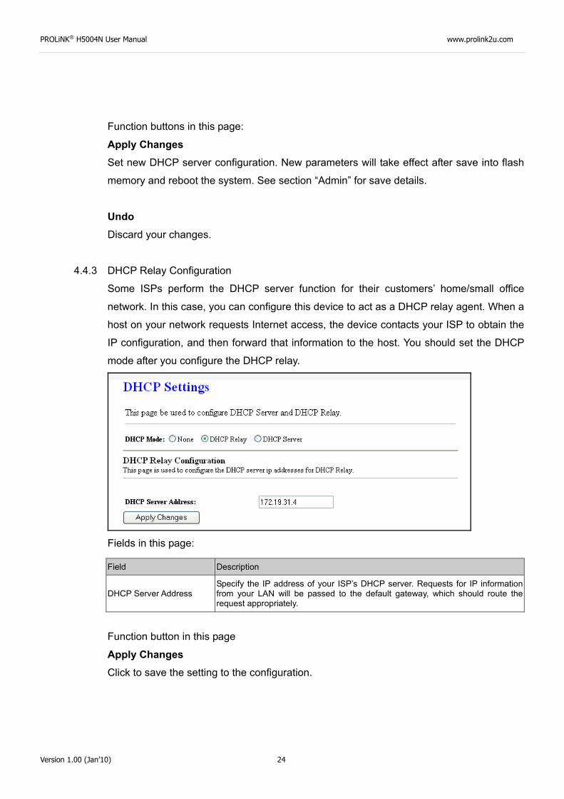
4.4.3 DHCP Relay Configuration
Some ISPs perform the DHCP server function for their customers’ home/small office
network. In this case, you can configure this device to act as a DHCP relay agent. When a
host on your network requests Internet access, the device contacts your ISP to obtain the
IP configuration, and then forward that information to the host. You should set the DHCP
mode after you configure the DHCP relay.
Fields in this page:
Function button in this page
Apply Changes Click to save the setting to the configuration.
Field Description
DHCP Server Address Specify the IP address of your ISP’s DHCP server. Requests for IP information from your LAN will be passed to the default gateway, which should route the request appropriately.
PROLiNK® H5004N User Manual www.prolink2u.com
Version 1.00 (Jan’10) 25
4.4.4 DNS Configuration
There are two submenus for the DNS Configuration: [DNS Server] and [Dynamic DNS]
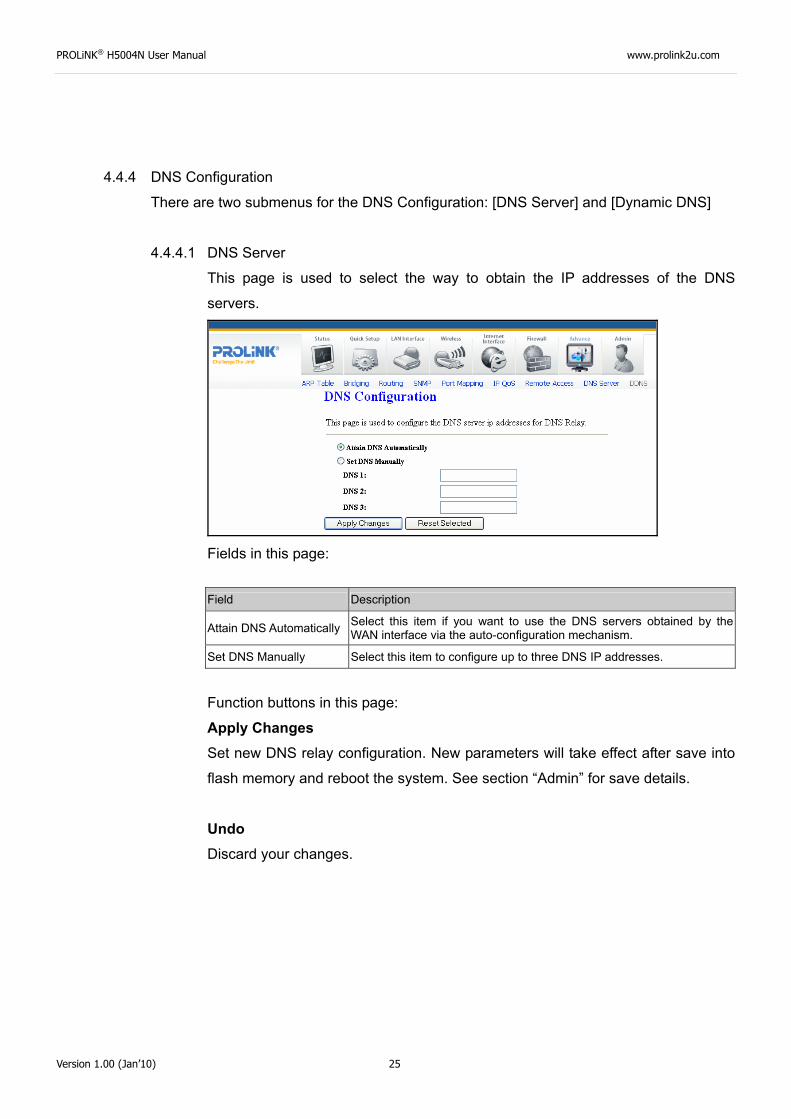
4.4.4.1 DNS Server
This page is used to select the way to obtain the IP addresses of the DNS
servers.
Fields in this page:
Function buttons in this page:
Apply Changes Set new DNS relay configuration. New parameters will take effect after save into
flash memory and reboot the system. See section “Admin” for save details.
Undo Discard your changes.
Field Description
Attain DNS Automatically Select this item if you want to use the DNS servers obtained by the WAN interface via the auto-configuration mechanism.
Set DNS Manually Select this item to configure up to three DNS IP addresses.
PROLiNK® H5004N User Manual www.prolink2u.com
Version 1.00 (Jan’10) 26
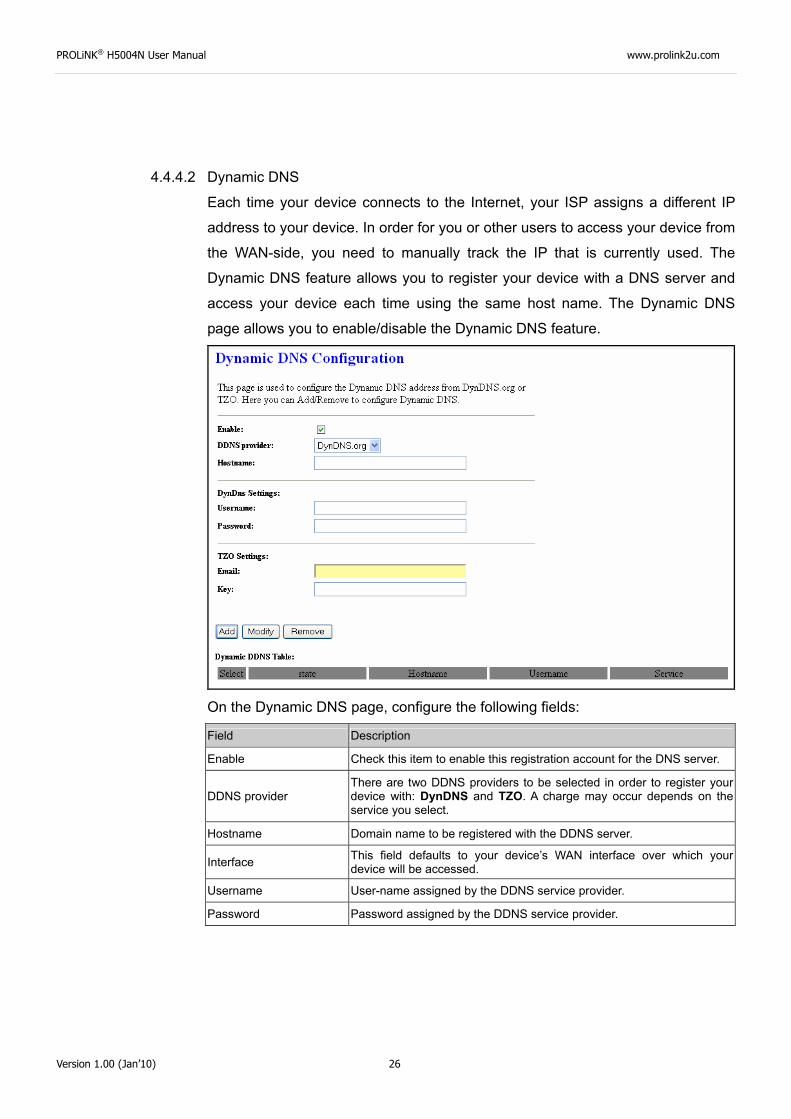
4.4.4.2 Dynamic DNS
Each time your device connects to the Internet, your ISP assigns a different IP
address to your device. In order for you or other users to access your device from
the WAN-side, you need to manually track the IP that is currently used. The
Dynamic DNS feature allows you to register your device with a DNS server and
access your device each time using the same host name. The Dynamic DNS
page allows you to enable/disable the Dynamic DNS feature.
On the Dynamic DNS page, configure the following fields:
Field Description
Enable Check this item to enable this registration account for the DNS server.
DDNS provider There are two DDNS providers to be selected in order to register your device with: DynDNS and TZO. A charge may occur depends on the service you select.
Hostname Domain name to be registered with the DDNS server.
Interface This field defaults to your device’s WAN interface over which your device will be accessed.
Username User-name assigned by the DDNS service provider.
Password Password assigned by the DDNS service provider.
PROLiNK® H5004N User Manual www.prolink2u.com
Version 1.00 (Jan’10) 27
Function buttons in this page:
Add Click Add to add this registration into the configuration.
Remove Select an existing DDNS registration by clicking the radio button at the Select
column of the Dynamic DNS Table. Click Remove button to remove the selected
registration from the configuration.
4.4.5 Firewall Configuration
Firewall contains several features that are used to deny or allow traffic from passing
through the device.
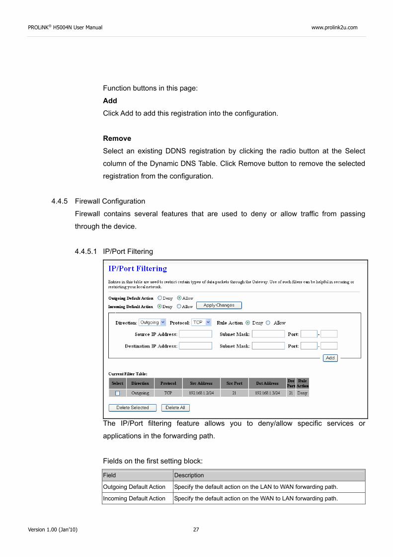
4.4.5.1 IP/Port Filtering
The IP/Port filtering feature allows you to deny/allow specific services or
applications in the forwarding path.
Fields on the first setting block:
Field Description
Outgoing Default Action Specify the default action on the LAN to WAN forwarding path.
Incoming Default Action Specify the default action on the WAN to LAN forwarding path.
PROLiNK® H5004N User Manual www.prolink2u.com
Version 1.00 (Jan’10) 28
Function button for this first setting block:
Apply Changes Click to save the setting of default actions to the configuration.
Fields on the second setting block:
Field Description
Rule Action Deny or allow traffic when matching this rule.
Direction Traffic forwarding direction.
Protocol There are 3 options available: TCP, UDP and ICMP.
Src IP Address The source IP address assigned to the traffic on which filtering is applied.
Src Subnet Mask Subnet-mask of the source IP.
Src Port Starting and ending source port numbers.
Dst IP Address The destination IP address assigned to the traffic on which filtering is applied.
Dst Subnet Mask Subnet-mask of the destination IP.
Dst Port Starting and ending destination port numbers.
Function buttons for this second setting block:
Apply Changes Click to save the rule entry to the configuration.
Function buttons for the Current Filter Table:
Delete Selected Delete selected filtering rules from the filter table. You can click the checkbox at
the Select column to select the filtering rule.
Delete All Delete all filtering rules from the filter table.
PROLiNK® H5004N User Manual www.prolink2u.com
Version 1.00 (Jan’10) 29
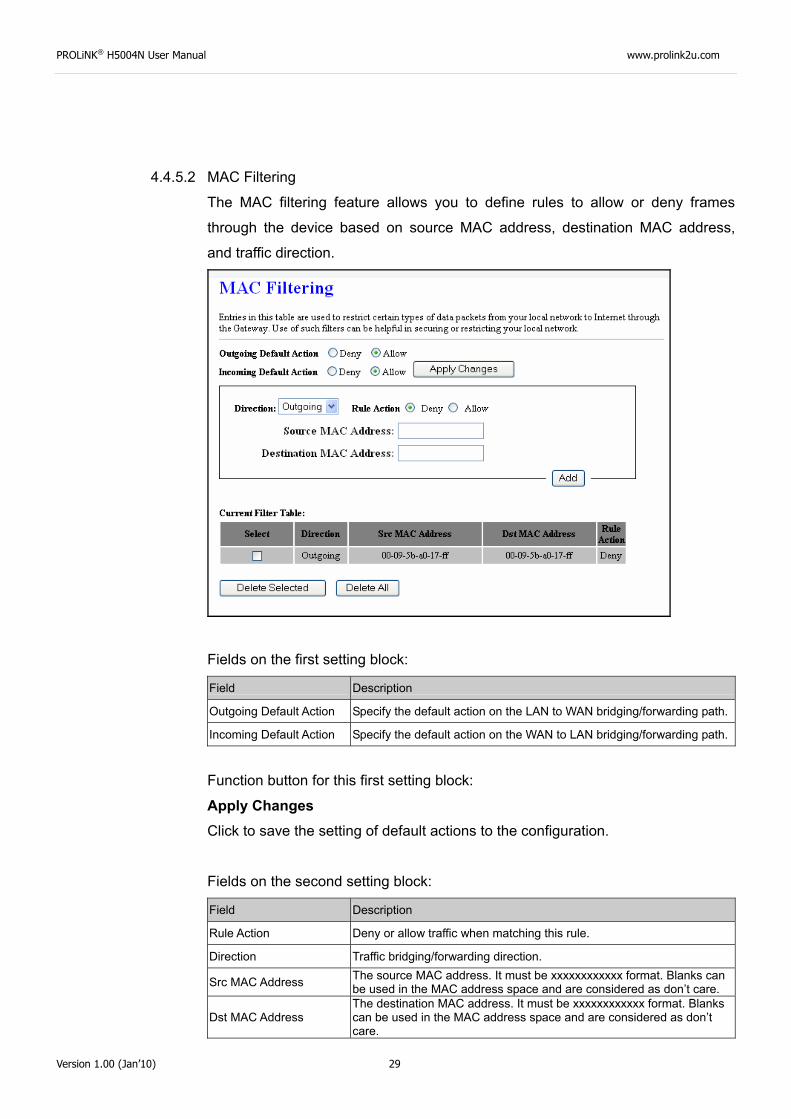
4.4.5.2 MAC Filtering
The MAC filtering feature allows you to define rules to allow or deny frames
through the device based on source MAC address, destination MAC address,
and traffic direction.
Fields on the first setting block:
Field Description
Outgoing Default Action Specify the default action on the LAN to WAN bridging/forwarding path.
Incoming Default Action Specify the default action on the WAN to LAN bridging/forwarding path.
Function button for this first setting block:
Apply Changes Click to save the setting of default actions to the configuration.
Fields on the second setting block:
Field Description
Rule Action Deny or allow traffic when matching this rule.
Direction Traffic bridging/forwarding direction.
Src MAC Address The source MAC address. It must be xxxxxxxxxxxx format. Blanks can be used in the MAC address space and are considered as don’t care.
Dst MAC Address The destination MAC address. It must be xxxxxxxxxxxx format. Blanks can be used in the MAC address space and are considered as don’t care.
PROLiNK® H5004N User Manual www.prolink2u.com
Version 1.00 (Jan’10) 30
Function buttons for this second setting block:
Apply Changes Click to save the rule entry to the configuration.
Function buttons for the Current Filter Table:
Delete Selected Delete selected filtering rules from the filter table. You can click the checkbox at
the Select column to select the filtering rule.
Delete All Delete all filtering rules from the filter table.
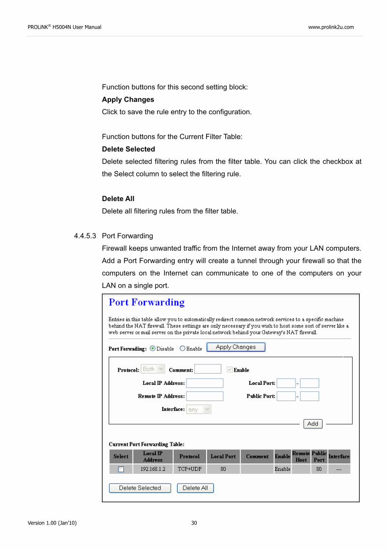
4.4.5.3 Port Forwarding
Firewall keeps unwanted traffic from the Internet away from your LAN computers.
Add a Port Forwarding entry will create a tunnel through your firewall so that the
computers on the Internet can communicate to one of the computers on your
LAN on a single port.
PROLiNK® H5004N User Manual www.prolink2u.com
Version 1.00 (Jan’10) 31
Fields in this page:
Field Description
Enable Port Forwarding Check this item to enable the port-forwarding feature.
Protocol There are 3 options available: TCP, UDP and Both.
Enable Check this item to enable this entry.
Local IP Address IP address of your local server that will be accessed by Internet.
Port The destination port number that is made open for this application on the LAN-side.
Remote IP Address The source IP address from which the incoming traffic is allowed. Leave blank for all.
External Port The destination port number that is made open for this application on the WAN-side
Interface Select the WAN interface on which the port-forwarding rule is to be applied.
Function buttons for the setting block:
Apply Changes Click to save the rule entry to the configuration.
Function buttons for the Current Port Forwarding Table:
Delete Selected Delete the selected port forwarding rules from the forwarding table. You can click
the checkbox at the Select column to select the forwarding rule.
Delete All Delete all forwarding rules from the forwarding table.
PROLiNK® H5004N User Manual www.prolink2u.com
Version 1.00 (Jan’10) 32
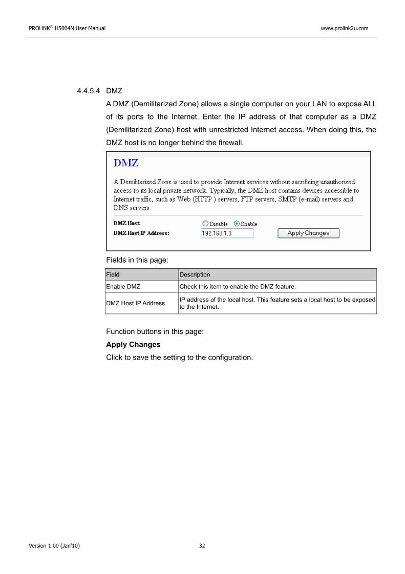
4.4.5.4 DMZ
A DMZ (Demilitarized Zone) allows a single computer on your LAN to expose ALL
of its ports to the Internet. Enter the IP address of that computer as a DMZ
(Demilitarized Zone) host with unrestricted Internet access. When doing this, the
DMZ host is no longer behind the firewall.
Fields in this page:
Field Description
Enable DMZ Check this item to enable the DMZ feature.
DMZ Host IP Address IP address of the local host. This feature sets a local host to be exposed to the Internet.
Function buttons in this page:
Apply Changes Click to save the setting to the configuration.
PROLiNK® H5004N User Manual www.prolink2u.com
Version 1.00 (Jan’10) 33
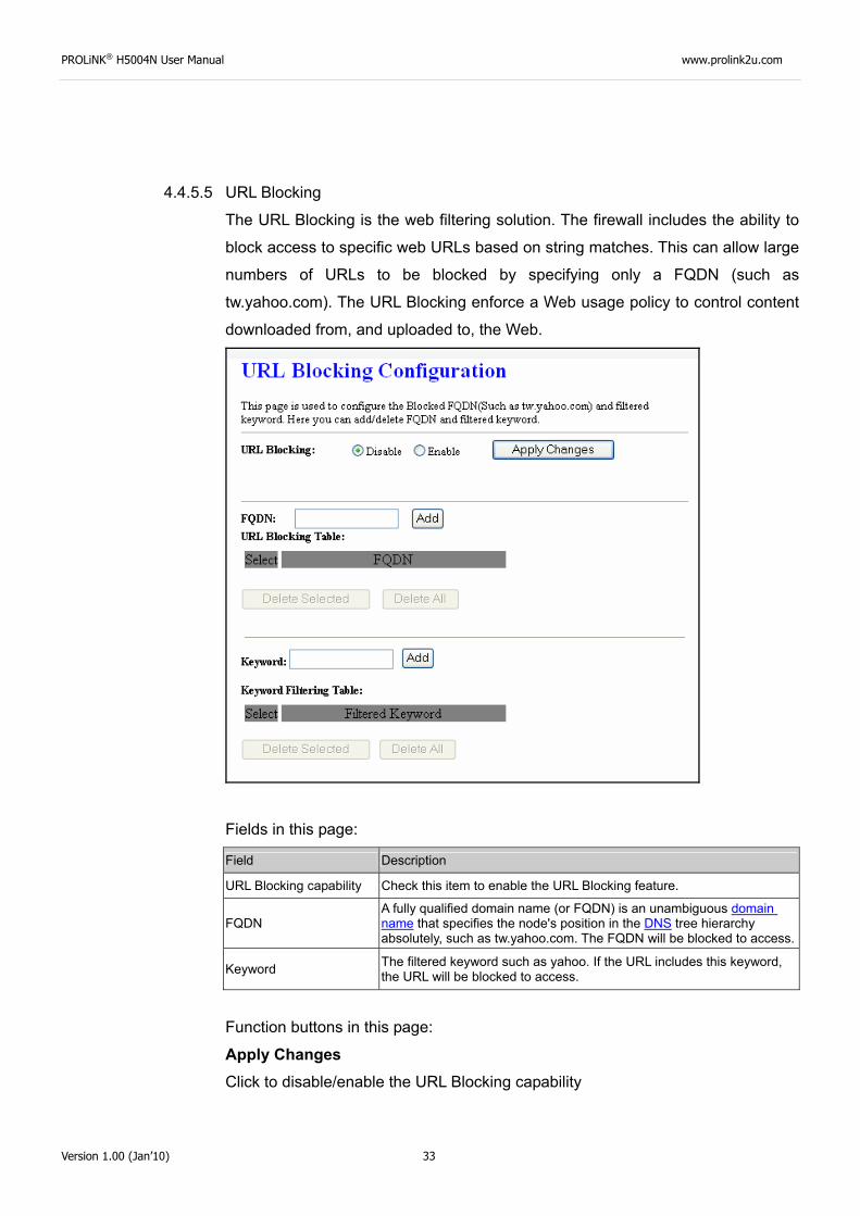
4.4.5.5 URL Blocking
The URL Blocking is the web filtering solution. The firewall includes the ability to
block access to specific web URLs based on string matches. This can allow large
numbers of URLs to be blocked by specifying only a FQDN (such as
tw.yahoo.com). The URL Blocking enforce a Web usage policy to control content
downloaded from, and uploaded to, the Web.
Fields in this page:
Field Description
URL Blocking capability Check this item to enable the URL Blocking feature.
FQDN A fully qualified domain name (or FQDN) is an unambiguous domain name that specifies the node's position in the DNS tree hierarchy absolutely, such as tw.yahoo.com. The FQDN will be blocked to access.
Keyword The filtered keyword such as yahoo. If the URL includes this keyword, the URL will be blocked to access.
Function buttons in this page:
Apply Changes Click to disable/enable the URL Blocking capability
PROLiNK® H5004N User Manual www.prolink2u.com
Version 1.00 (Jan’10) 34
Add FQDN Add FQDN into URL Blocking table.
Delete Selected FQDN Delete the selected FQDN from the URL Blocking table. You can click the
checkbox at the Select column to select the Blocked FQDN.
Add Filtered Keyword Add filtered keyword into Keyword Filtering table.
Delete Selected Keyword Delete the selected keyword from the keyword Filtering table. You can click the
checkbox at the Select column to select the filtered keyword.
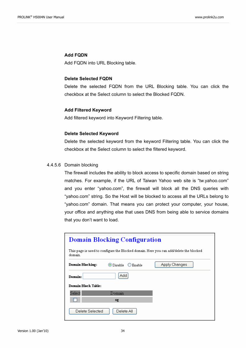
4.4.5.6 Domain blocking
The firewall includes the ability to block access to specific domain based on string
matches. For example, if the URL of Taiwan Yahoo web site is “tw.yahoo.com”
and you enter “yahoo.com”, the firewall will block all the DNS queries with
“yahoo.com” string. So the Host will be blocked to access all the URLs belong to
“yahoo.com” domain. That means you can protect your computer, your house,
your office and anything else that uses DNS from being able to service domains
that you don’t want to load.
PROLiNK® H5004N User Manual www.prolink2u.com
Version 1.00 (Jan’10) 35
Fields in this page:
Field Description
Domain Blocking capability Check this item to enable the Domain Blocking feature.
Domain The blocked domain. If the URL of Taiwan Yahoo web site is tw.yahoo.com, the domain can be yahoo.com.
Function buttons in this page:
Apply Changes Click to disable/enable the Domain Block capability
Add Domain Add domain into Domain Block table.
Delete Selected Domain Delete the selected domain from the Domain Block table. You can click the
checkbox at the Select column to select the Blocked domain.
4.4.6 IGMP Proxy Configuration
Multicasting is useful when the same data needs to be sent to more than one hosts. Using
multicasting as opposed to sending the same data to the individual hosts uses less
network bandwidth. The multicast feature also enables you to receive multicast video
stream from multicast servers.
IP hosts use Internet Group Management Protocol (IGMP) to report their multicast group
memberships to neighboring routers. Similarly, multicast routers use IGMP to discover
which of their hosts belong to multicast groups. This device supports IGMP proxy that
handles IGMP messages. When enabled, this device acts as a proxy for a LAN host
making requests to join and leave multicast groups, or a multicast router sending multicast
packets to multicast group on the WAN side.
When a host wishes to join a multicast group, it sends IGMP REPORT message to the
device’s IGMP downstream interface. The proxy sets up a multicast route for the interface
and host requesting the video content. It then forwards the Join to the upstream multicast
router. The multicast IP traffic will then be forwarded to the requesting host. On a leave,
the proxy removes the route and then forwards the leave to the upstream multicast router.
PROLiNK® H5004N User Manual www.prolink2u.com
Version 1.00 (Jan’10) 36
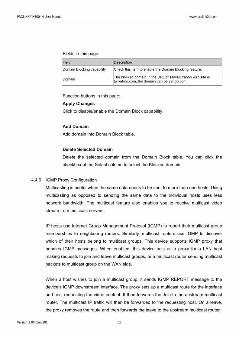
The IGMP Proxy page allows you to enable multicast on WAN and LAN interfaces. The
LAN interface is always served as downstream IGMP proxy, and you can configure one of
the available WAN interfaces as the upstream IGMP proxy.
Upstream: The interfaces that IGMP requests from hosts are sent to the multicast router.
Downstream: The interface data from the multicast router are sent to hosts in the
multicast group database.
Fields in this page:
Field Description
IGMP Proxy Enable/disable IGMP proxy feature
Proxy Interface The upstream WAN interface is selected here.
Function buttons in this page:
Apply Changes Click to save the setting to the configuration.
Undo Discard your settings.
PROLiNK® H5004N User Manual www.prolink2u.com
Version 1.00 (Jan’10) 37
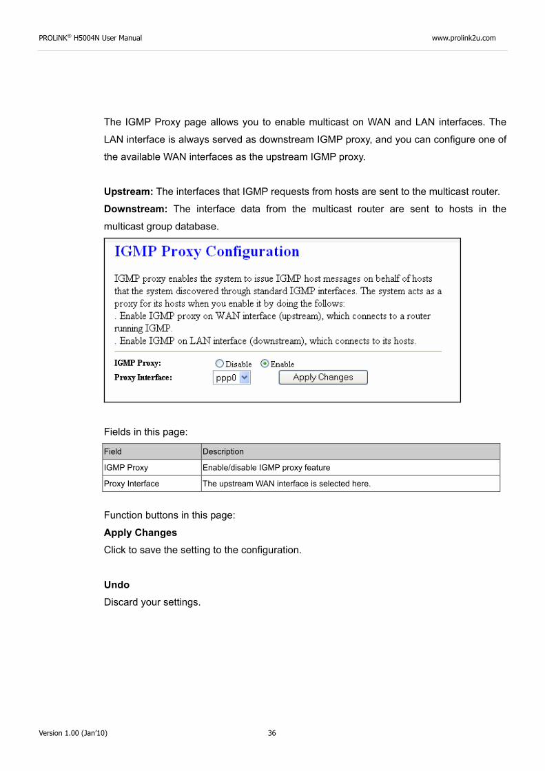
4.4.7 UPnP Configuration
The DSL device supports a control point for Universal Plug and Play (UPnP) version 1.0,
and supports two key features: NAT Traversal and Device Identification. This feature
requires one active WAN interface. In addition, the host should support this feature. In the
presence of multiple WAN interfaces, select an interface on which the incoming traffic is
present.
With NAT Traversal, when an UPnP command is received to open ports in NAT, the
application translates the request into system commands to open the ports in NAT and the
firewall. The interface to open the ports on is given to UPnP when it starts up and is part of
the configuration of the application.
For Device Identification, the application will send a description of the DSL device as a
control point back to the host making the request.
Fields in this page:
Field Description
UPnP Daemon Enable/disable UPnP feature.
Binded WAN Interface Select WAN interface that will use UPnP from the drop-down lists.
Function buttons in this page:
Apply Changes Click to save the setting to the system configuration.
PROLiNK® H5004N User Manual www.prolink2u.com
Version 1.00 (Jan’10) 38
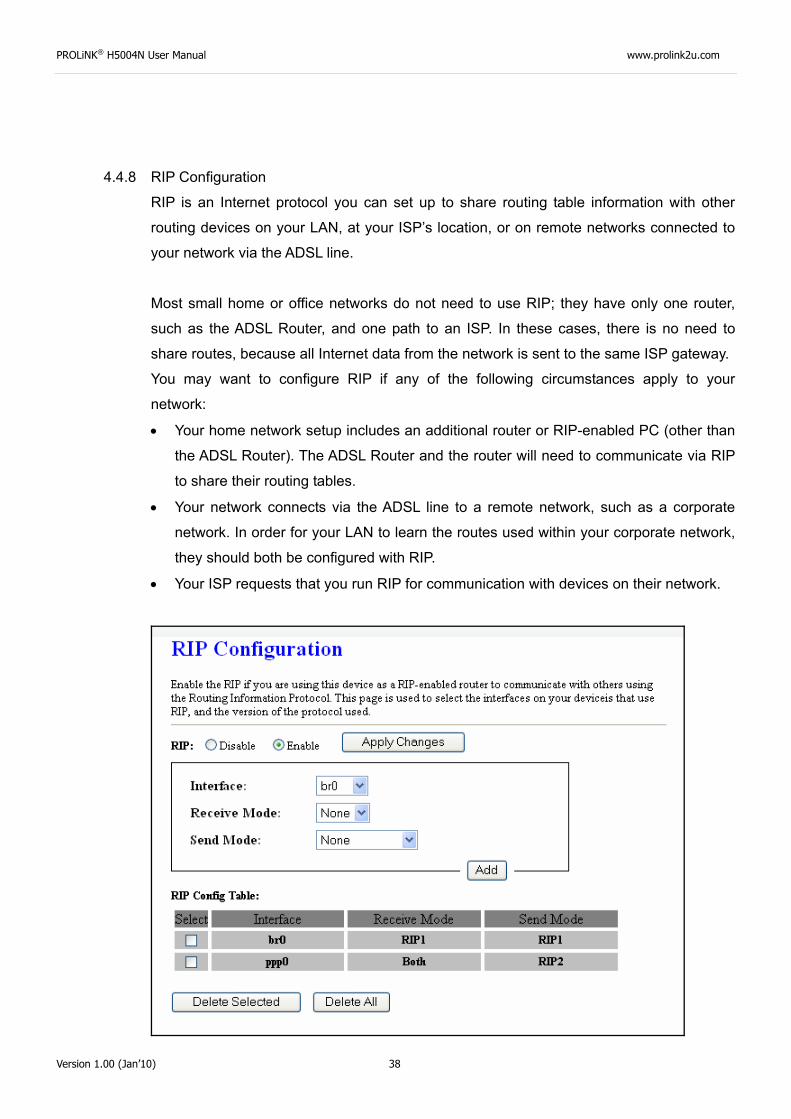
4.4.8 RIP Configuration
RIP is an Internet protocol you can set up to share routing table information with other
routing devices on your LAN, at your ISP’s location, or on remote networks connected to
your network via the ADSL line.
Most small home or office networks do not need to use RIP; they have only one router,
such as the ADSL Router, and one path to an ISP. In these cases, there is no need to
share routes, because all Internet data from the network is sent to the same ISP gateway.
You may want to configure RIP if any of the following circumstances apply to your
network:
• Your home network setup includes an additional router or RIP-enabled PC (other than
the ADSL Router). The ADSL Router and the router will need to communicate via RIP
to share their routing tables.
• Your network connects via the ADSL line to a remote network, such as a corporate
network. In order for your LAN to learn the routes used within your corporate network,
they should both be configured with RIP.
• Your ISP requests that you run RIP for communication with devices on their network.
PROLiNK® H5004N User Manual www.prolink2u.com
Version 1.00 (Jan’10) 39
Fields on the first setting block:
Field Description
RIP Enable/disable RIP feature.
Function buttons for the second setting block in this page:
Apply Changes Click to save the setting of this setting block to the system configuration
Fields on the second setting block:
Field Description
Interface The name of the interface on which you want to enable RIP.
Receive Mode Indicate the RIP version in which information must be passed to the DSL device in order for it to be accepted into its routing table.
Send Mode Indicate the RIP version this interface will use when it sends its route information to other devices.
Function buttons for the second setting block in this page:
Add Add a RIP entry and the new RIP entry will be display in the table
Delete Selected Entry Delete a selected RIP entry. The RIP entry can be selected on the Select column of the
RIP Config Table.
4.5 Advance Configuration
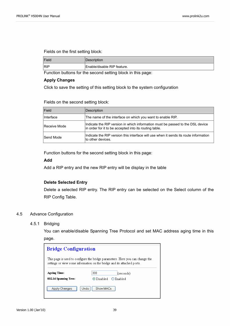
4.5.1 Bridging
You can enable/disable Spanning Tree Protocol and set MAC address aging time in this
page.
PROLiNK® H5004N User Manual www.prolink2u.com
Version 1.00 (Jan’10) 40
Fields in this page:
Field Description
Ageing Time Set the Ethernet address ageing time, in seconds. After [Ageing Time] seconds of not having seen a frame coming from a certain address, the bridge will time out (delete) that address from Forwarding DataBase (fdb).
802.1d Spanning Tree Enable/disable the spanning tree protocol
Function buttons in this page:
Apply Changes Save this bridge configuration. New configuration will take effect after saving into flash
memory and rebooting the system. See section “Admin” for details.
Show MACs List MAC address in forwarding table.
4.5.2 Routing
The Routing page enables you to define specific route for your Internet and network data.
Most users do not need to define routes. On a typical small home or office LAN, the
existing routes that set up the default gateways for your LAN hosts and for the DSL device
provide the most appropriate path for all your Internet traffic.
On your LAN hosts, a default gateway directs all Internet traffic to the LAN port(s) on the
DSL device. Your LAN hosts know their default gateway either because you assigned it to
them when you modified your TCP/IP properties, or because you configured them to
receive the information dynamically from a server whenever they access the Internet.
On the DSL device itself, a default gateway is defined to direct all outbound Internet traffic
to a route at your ISP. The default gateway is assigned either automatically by your ISP
whenever the device negotiates an Internet access, or manually by user to setup through
the configuration.
You may need to define routes if your home setup includes two or more networks or
subnets, if you connect to two or more ISP services, or if you connect to a remote
corporate LAN.
PROLiNK® H5004N User Manual www.prolink2u.com
Version 1.00 (Jan’10) 41
:
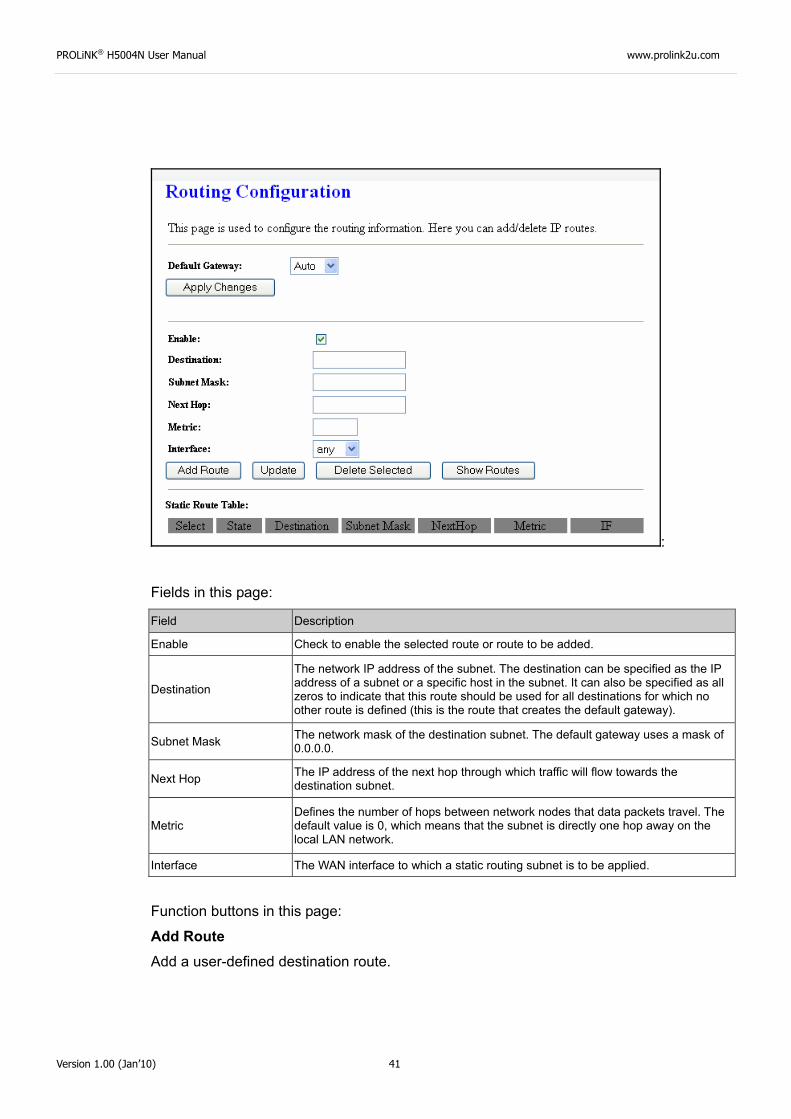
Fields in this page:
Field Description
Enable Check to enable the selected route or route to be added.
Destination
The network IP address of the subnet. The destination can be specified as the IP address of a subnet or a specific host in the subnet. It can also be specified as all zeros to indicate that this route should be used for all destinations for which no other route is defined (this is the route that creates the default gateway).
Subnet Mask The network mask of the destination subnet. The default gateway uses a mask of 0.0.0.0.
Next Hop The IP address of the next hop through which traffic will flow towards the destination subnet.
Metric Defines the number of hops between network nodes that data packets travel. The default value is 0, which means that the subnet is directly one hop away on the local LAN network.
Interface The WAN interface to which a static routing subnet is to be applied.
Function buttons in this page:
Add Route Add a user-defined destination route.
PROLiNK® H5004N User Manual www.prolink2u.com
Version 1.00 (Jan’10) 42
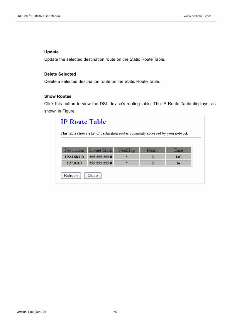
Update Update the selected destination route on the Static Route Table.
Delete Selected Delete a selected destination route on the Static Route Table.
Show Routes Click this button to view the DSL device’s routing table. The IP Route Table displays, as
shown in Figure.
PROLiNK® H5004N User Manual www.prolink2u.com
Version 1.00 (Jan’10) 43
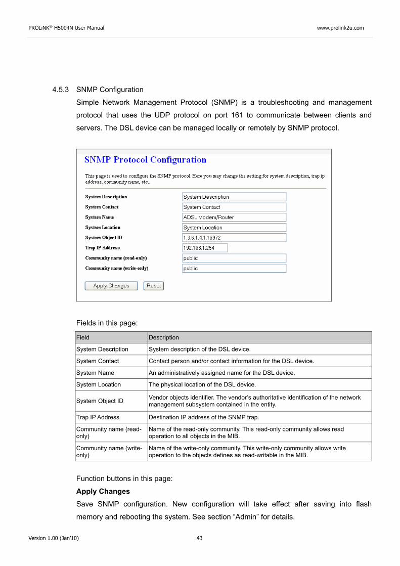
4.5.3 SNMP Configuration
Simple Network Management Protocol (SNMP) is a troubleshooting and management
protocol that uses the UDP protocol on port 161 to communicate between clients and
servers. The DSL device can be managed locally or remotely by SNMP protocol.
Fields in this page:
Field Description
System Description System description of the DSL device.
System Contact Contact person and/or contact information for the DSL device.
System Name An administratively assigned name for the DSL device.
System Location The physical location of the DSL device.
System Object ID Vendor objects identifier. The vendor’s authoritative identification of the network management subsystem contained in the entity.
Trap IP Address Destination IP address of the SNMP trap.
Community name (read-only)
Name of the read-only community. This read-only community allows read operation to all objects in the MIB.
Community name (write-only)
Name of the write-only community. This write-only community allows write operation to the objects defines as read-writable in the MIB.
Function buttons in this page:
Apply Changes Save SNMP configuration. New configuration will take effect after saving into flash
memory and rebooting the system. See section “Admin” for details.
PROLiNK® H5004N User Manual www.prolink2u.com
Version 1.00 (Jan’10) 44
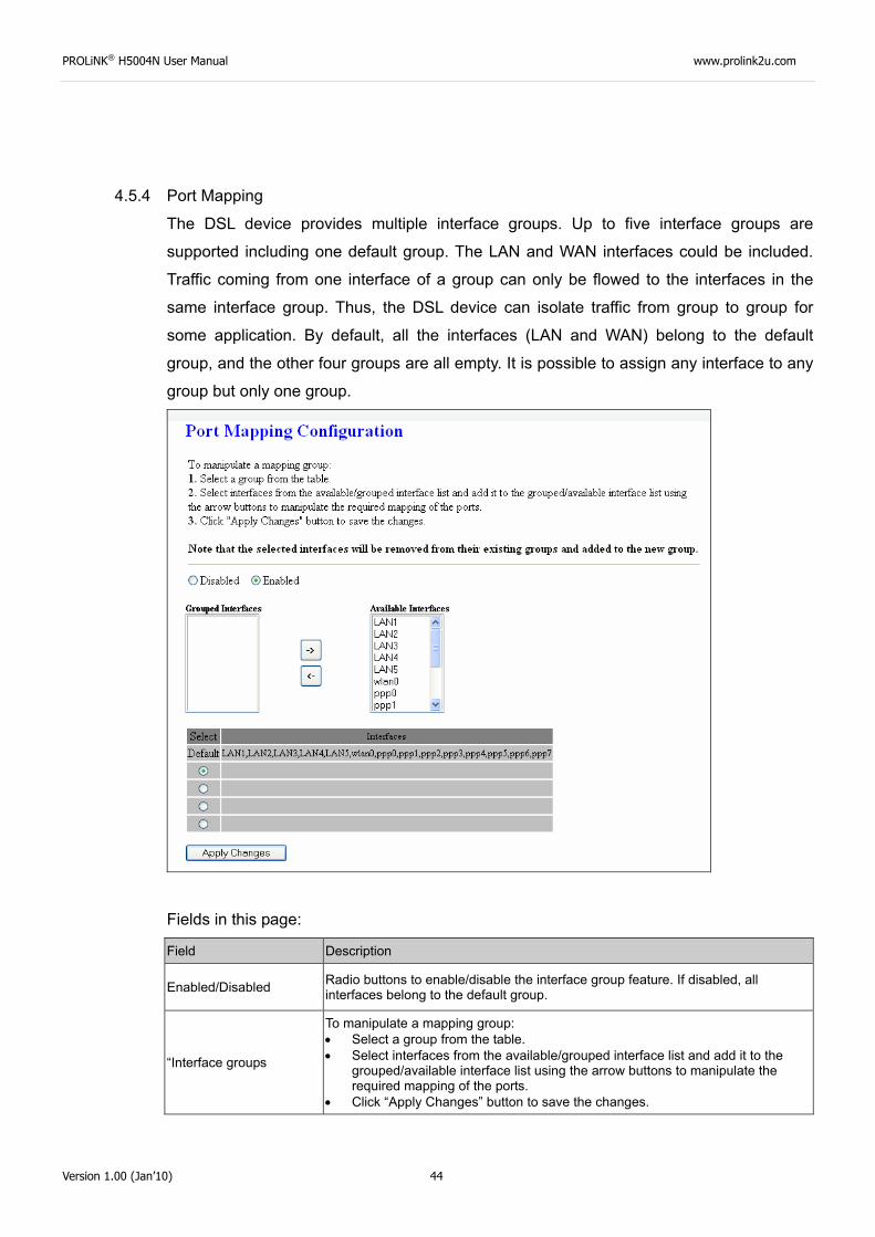
4.5.4 Port Mapping
The DSL device provides multiple interface groups. Up to five interface groups are
supported including one default group. The LAN and WAN interfaces could be included.
Traffic coming from one interface of a group can only be flowed to the interfaces in the
same interface group. Thus, the DSL device can isolate traffic from group to group for
some application. By default, all the interfaces (LAN and WAN) belong to the default
group, and the other four groups are all empty. It is possible to assign any interface to any
group but only one group.
Fields in this page:
Field Description
Enabled/Disabled Radio buttons to enable/disable the interface group feature. If disabled, all interfaces belong to the default group.
“Interface groups
To manipulate a mapping group: • Select a group from the table. • Select interfaces from the available/grouped interface list and add it to the
grouped/available interface list using the arrow buttons to manipulate the required mapping of the ports.
• Click “Apply Changes” button to save the changes.
PROLiNK® H5004N User Manual www.prolink2u.com
Version 1.00 (Jan’10) 45
Function buttons in this page:
Apply Changes Save configuration to system. New configuration will take effect after saving into flash
memory and rebooting the system. See section “Admin” for details.
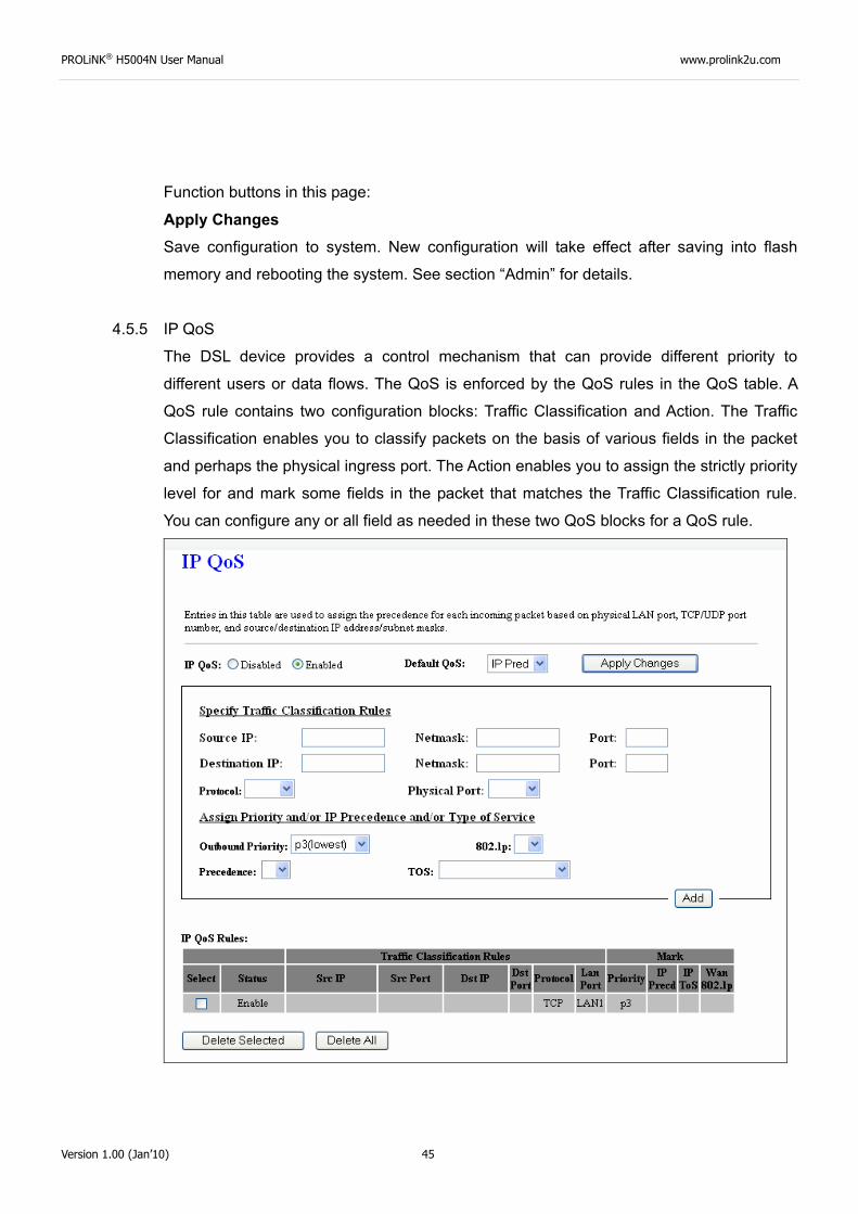
4.5.5 IP QoS
The DSL device provides a control mechanism that can provide different priority to
different users or data flows. The QoS is enforced by the QoS rules in the QoS table. A
QoS rule contains two configuration blocks: Traffic Classification and Action. The Traffic
Classification enables you to classify packets on the basis of various fields in the packet
and perhaps the physical ingress port. The Action enables you to assign the strictly priority
level for and mark some fields in the packet that matches the Traffic Classification rule.
You can configure any or all field as needed in these two QoS blocks for a QoS rule.
PROLiNK® H5004N User Manual www.prolink2u.com
Version 1.00 (Jan’10) 46
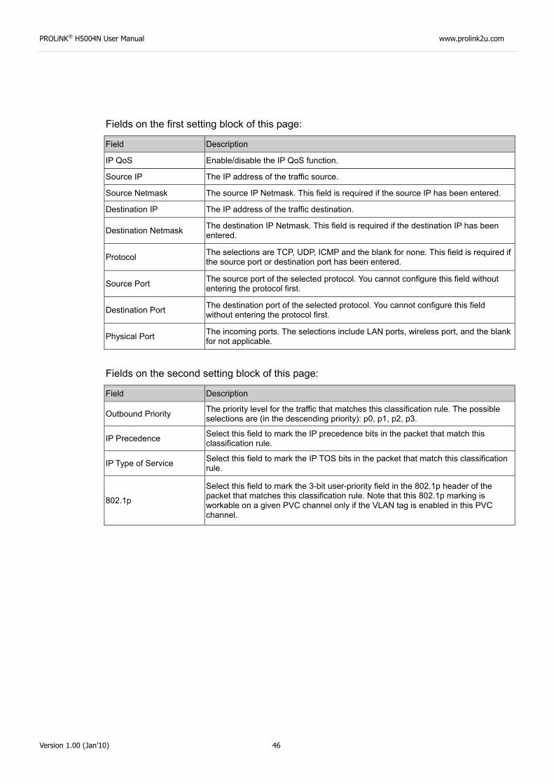
Fields on the first setting block of this page:
Field Description
IP QoS Enable/disable the IP QoS function.
Source IP The IP address of the traffic source.
Source Netmask The source IP Netmask. This field is required if the source IP has been entered.
Destination IP The IP address of the traffic destination.
Destination Netmask The destination IP Netmask. This field is required if the destination IP has been entered.
Protocol The selections are TCP, UDP, ICMP and the blank for none. This field is required if the source port or destination port has been entered.
Source Port The source port of the selected protocol. You cannot configure this field without entering the protocol first.
Destination Port The destination port of the selected protocol. You cannot configure this field without entering the protocol first.
Physical Port The incoming ports. The selections include LAN ports, wireless port, and the blank for not applicable.
Fields on the second setting block of this page:
Field Description
Outbound Priority The priority level for the traffic that matches this classification rule. The possible selections are (in the descending priority): p0, p1, p2, p3.
IP Precedence Select this field to mark the IP precedence bits in the packet that match this classification rule.
IP Type of Service Select this field to mark the IP TOS bits in the packet that match this classification rule.
802.1p
Select this field to mark the 3-bit user-priority field in the 802.1p header of the packet that matches this classification rule. Note that this 802.1p marking is workable on a given PVC channel only if the VLAN tag is enabled in this PVC channel.
PROLiNK® H5004N User Manual www.prolink2u.com
Version 1.00 (Jan’10) 47
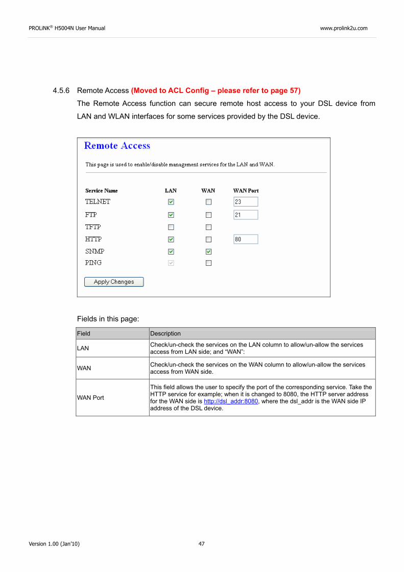
4.5.6 Remote Access (Moved to ACL Config – please refer to page 57) The Remote Access function can secure remote host access to your DSL device from
LAN and WLAN interfaces for some services provided by the DSL device.
Fields in this page:
Field Description
LAN Check/un-check the services on the LAN column to allow/un-allow the services access from LAN side; and “WAN”:
WAN Check/un-check the services on the WAN column to allow/un-allow the services access from WAN side.
WAN Port
This field allows the user to specify the port of the corresponding service. Take the HTTP service for example; when it is changed to 8080, the HTTP server address for the WAN side is http://dsl_addr:8080, where the dsl_addr is the WAN side IP address of the DSL device.
PROLiNK® H5004N User Manual www.prolink2u.com
Version 1.00 (Jan’10) 48
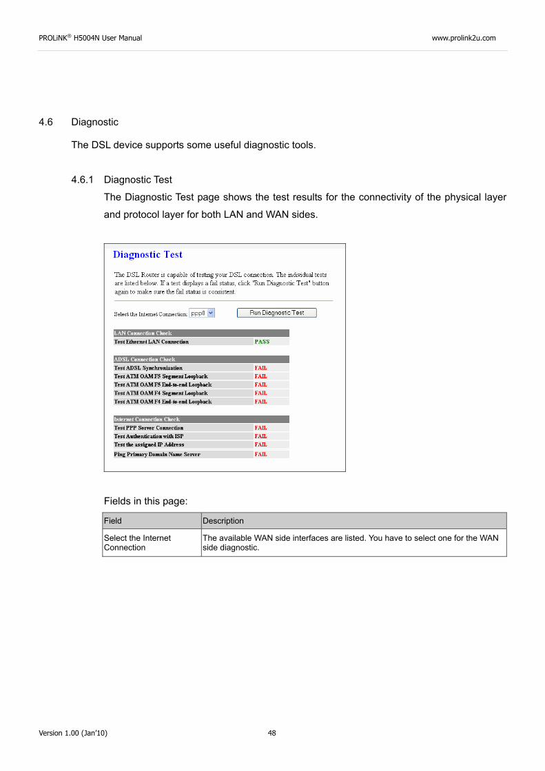
4.6 Diagnostic
The DSL device supports some useful diagnostic tools.
4.6.1 Diagnostic Test
The Diagnostic Test page shows the test results for the connectivity of the physical layer
and protocol layer for both LAN and WAN sides.
Fields in this page:
Field Description
Select the Internet Connection
The available WAN side interfaces are listed. You have to select one for the WAN side diagnostic.
PROLiNK® H5004N User Manual www.prolink2u.com
Version 1.00 (Jan’10) 49
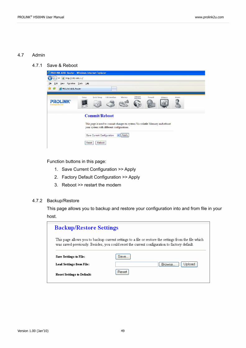
4.7 Admin
4.7.1 Save & Reboot
Function buttons in this page:
1. Save Current Configuration >> Apply
2. Factory Default Configuration >> Apply
3. Reboot >> restart the modem
4.7.2 Backup/Restore
This page allows you to backup and restore your configuration into and from file in your
host.
PROLiNK® H5004N User Manual www.prolink2u.com
Version 1.00 (Jan’10) 50
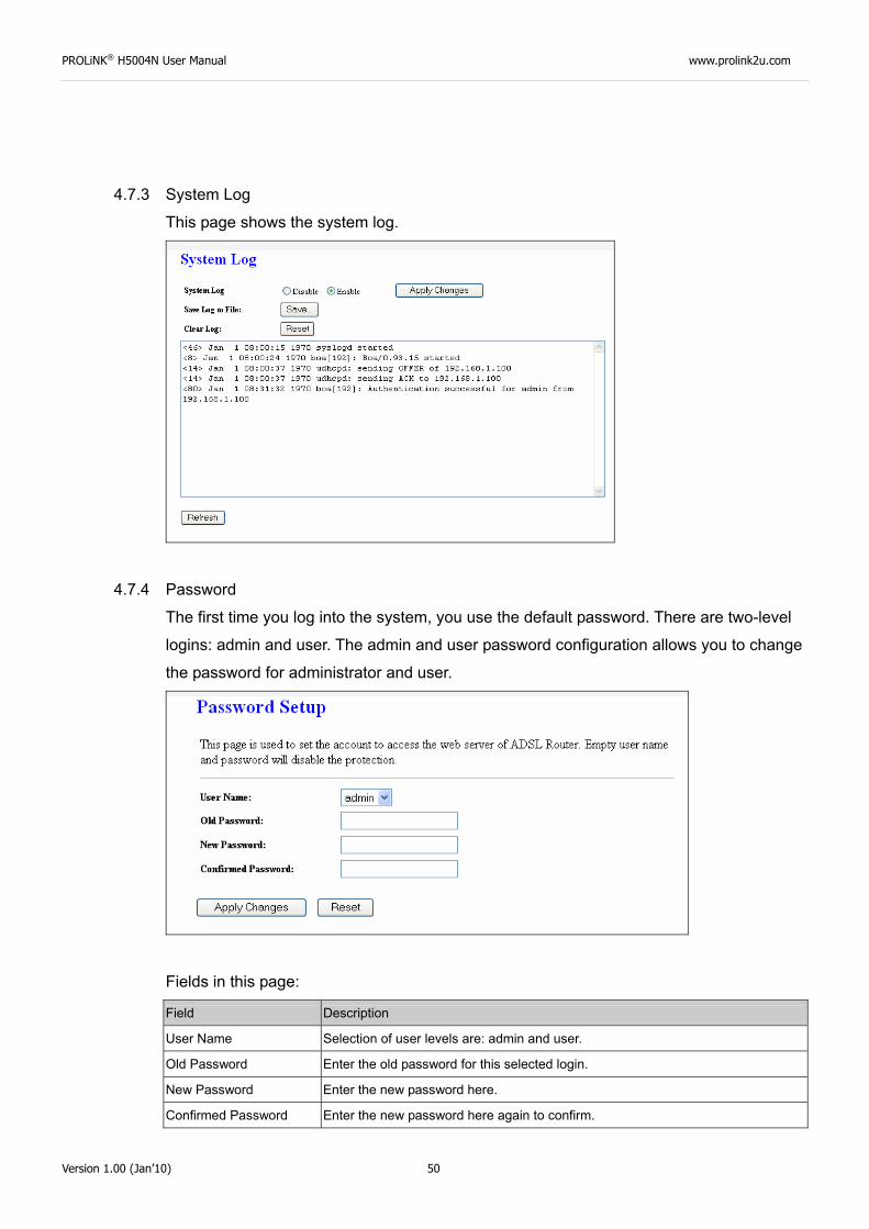
4.7.3 System Log
This page shows the system log.
4.7.4 Password
The first time you log into the system, you use the default password. There are two-level
logins: admin and user. The admin and user password configuration allows you to change
the password for administrator and user.
Fields in this page:
Field Description
User Name Selection of user levels are: admin and user.
Old Password Enter the old password for this selected login.
New Password Enter the new password here.
Confirmed Password Enter the new password here again to confirm.
PROLiNK® H5004N User Manual www.prolink2u.com
Version 1.00 (Jan’10) 51
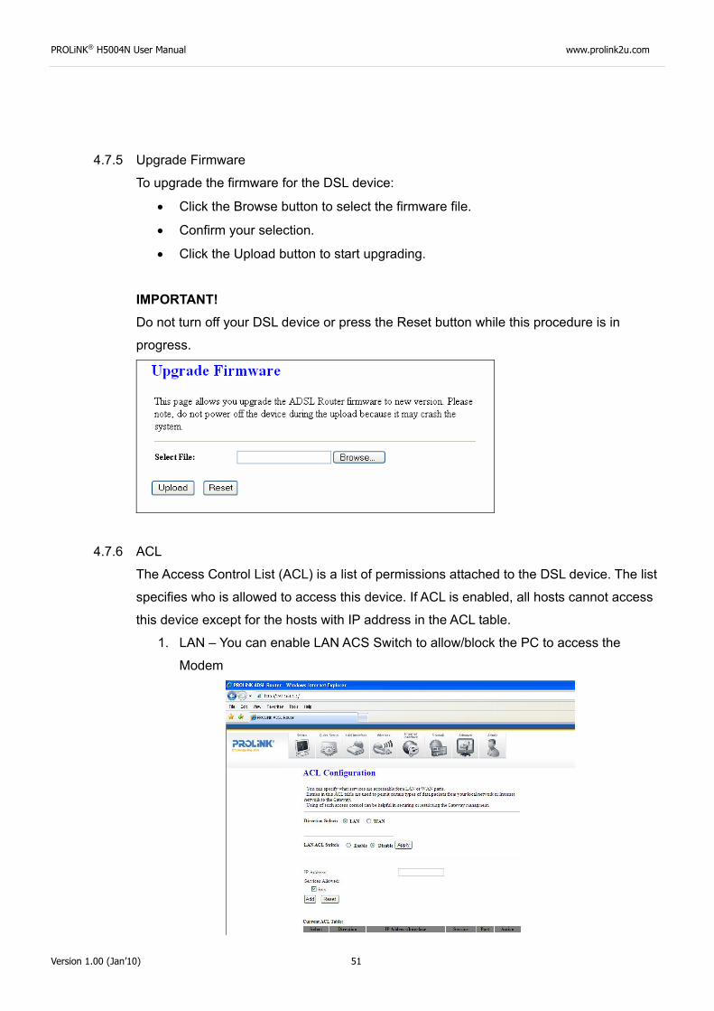
4.7.5 Upgrade Firmware
To upgrade the firmware for the DSL device:
• Click the Browse button to select the firmware file.
• Confirm your selection.
• Click the Upload button to start upgrading.
IMPORTANT! Do not turn off your DSL device or press the Reset button while this procedure is in
progress.
4.7.6 ACL
The Access Control List (ACL) is a list of permissions attached to the DSL device. The list
specifies who is allowed to access this device. If ACL is enabled, all hosts cannot access
this device except for the hosts with IP address in the ACL table.
1. LAN – You can enable LAN ACS Switch to allow/block the PC to access the
Modem
PROLiNK® H5004N User Manual www.prolink2u.com
Version 1.00 (Jan’10) 52
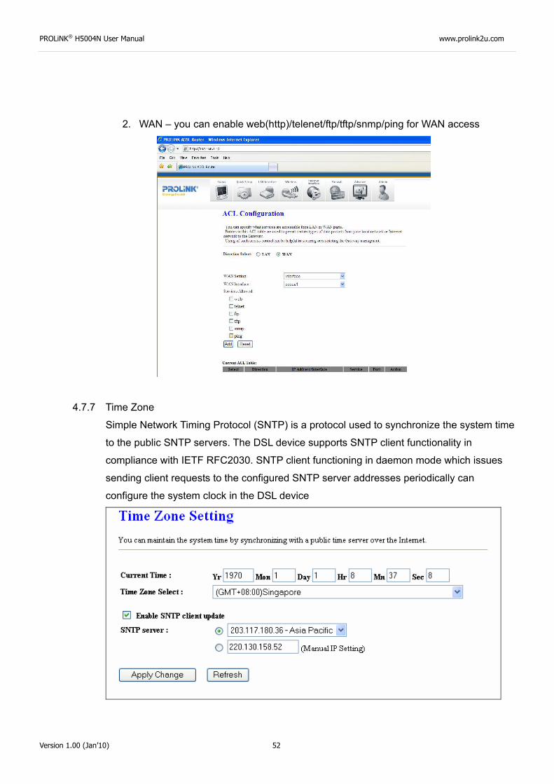
2. WAN – you can enable web(http)/telenet/ftp/tftp/snmp/ping for WAN access
4.7.7 Time Zone
Simple Network Timing Protocol (SNTP) is a protocol used to synchronize the system time
to the public SNTP servers. The DSL device supports SNTP client functionality in
compliance with IETF RFC2030. SNTP client functioning in daemon mode which issues
sending client requests to the configured SNTP server addresses periodically can
configure the system clock in the DSL device
PROLiNK® H5004N User Manual www.prolink2u.com
Version 1.00 (Jan’10) 53
Fields in this page:
Field Description
Current Time The current time of the specified time zone. You can set the current time by yourself or configured by SNTP.
Time Zone Select The time zone in which the DSL device resides. Enable SNTP client update Enable the SNTP client to update the system clock.
SNTP server The IP address or the host name of the SNTP server. You can select from the list or set it manually.
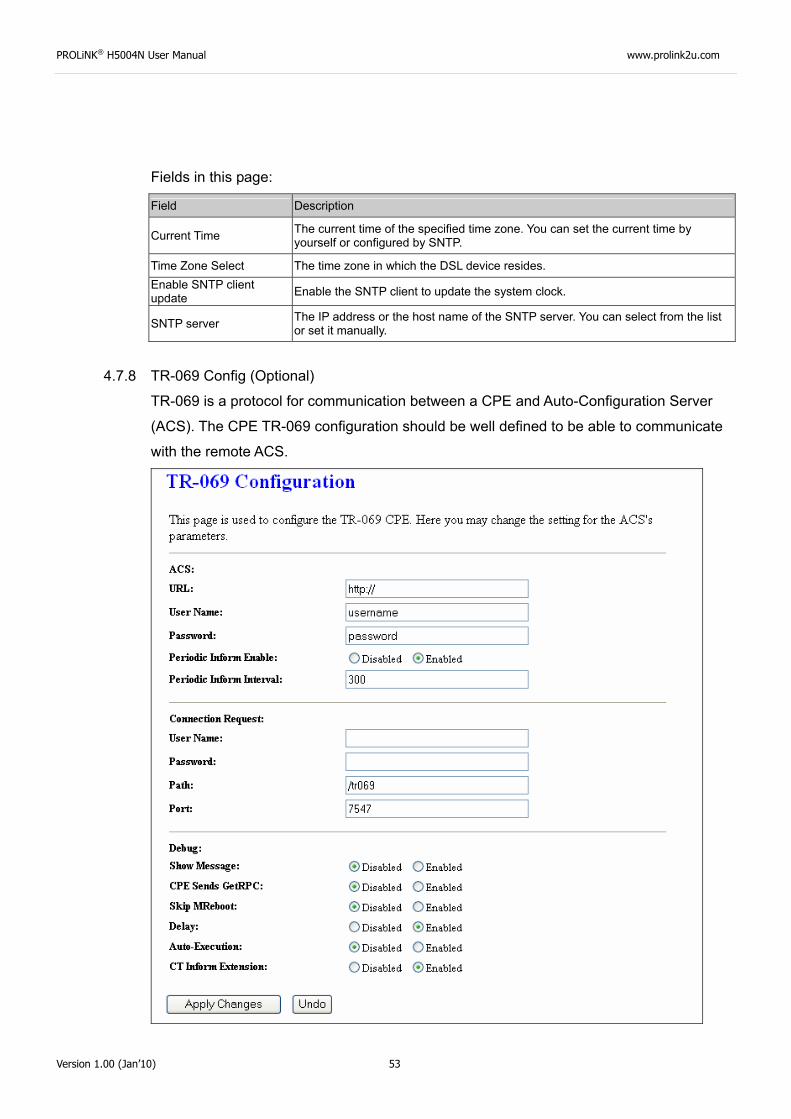
4.7.8 TR-069 Config (Optional)
TR-069 is a protocol for communication between a CPE and Auto-Configuration Server
(ACS). The CPE TR-069 configuration should be well defined to be able to communicate
with the remote ACS.
PROLiNK® H5004N User Manual www.prolink2u.com
Version 1.00 (Jan’10) 54
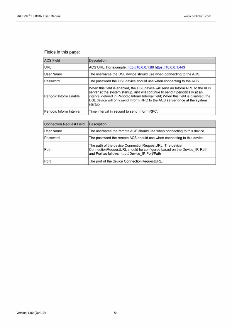
Fields in this page:
ACS Field Description
URL ACS URL. For example, http://10.0.0.1:80 https://10.0.0.1:443
User Name The username the DSL device should use when connecting to the ACS.
Password The password the DSL device should use when connecting to the ACS.
Periodic Inform Enable
When this field is enabled, the DSL device will send an Inform RPC to the ACS server at the system startup, and will continue to send it periodically at an interval defined in Periodic Inform Interval field; When this field is disabled, the DSL device will only send Inform RPC to the ACS server once at the system startup.
Periodic Inform Interval Time interval in second to send Inform RPC.
Connection Request Field Description
User Name The username the remote ACS should use when connecting to this device.
Password The password the remote ACS should use when connecting to this device.
Path The path of the device ConnectionRequestURL. The device ConnectionRequestURL should be configured based on the Device_IP, Path and Port as follows: http://Device_IP:Port/Path
Port The port of the device ConnectionRequestURL.
PROLiNK® H5004N User Manual www.prolink2u.com
Version 1.00 (Jan’10) 55
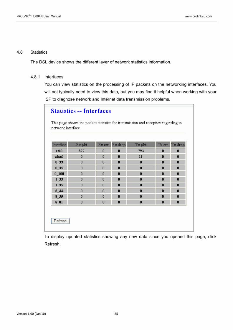
4.8 Statistics
The DSL device shows the different layer of network statistics information.
4.8.1 Interfaces
You can view statistics on the processing of IP packets on the networking interfaces. You
will not typically need to view this data, but you may find it helpful when working with your
ISP to diagnose network and Internet data transmission problems.
To display updated statistics showing any new data since you opened this page, click
Refresh.
PROLiNK® H5004N User Manual www.prolink2u.com
Version 1.00 (Jan’10) 56
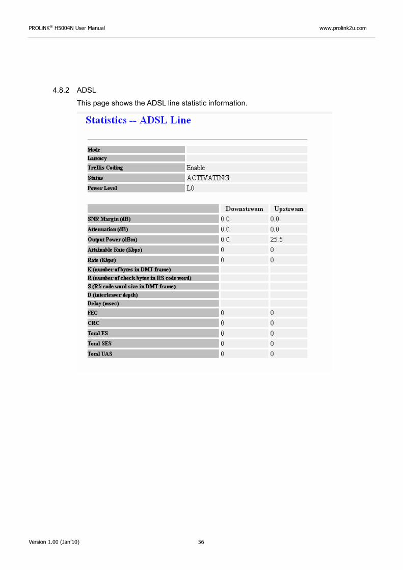
4.8.2 ADSL
This page shows the ADSL line statistic information.
PROLiNK® H5004N User Manual www.prolink2u.com
Version 1.00 (Jan’10) 57
Chapter 5
Channel Mode Configuration
ADSL router supports multiple channel operation modes. This section will show procedures to configure
the router.
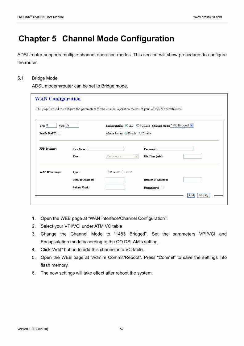
5.1 Bridge Mode
ADSL modem/router can be set to Bridge mode.
1. Open the WEB page at “WAN interface/Channel Configuration”.
2. Select your VPI/VCI under ATM VC table
3. Change the Channel Mode to “1483 Bridged”. Set the parameters VPI/VCI and
Encapsulation mode according to the CO DSLAM’s setting.
4. Click “Add” button to add this channel into VC table.
5. Open the WEB page at “Admin/ Commit/Reboot”. Press “Commit” to save the settings into
flash memory.
6. The new settings will take effect after reboot the system.
PROLiNK® H5004N User Manual www.prolink2u.com
Version 1.00 (Jan’10) 58
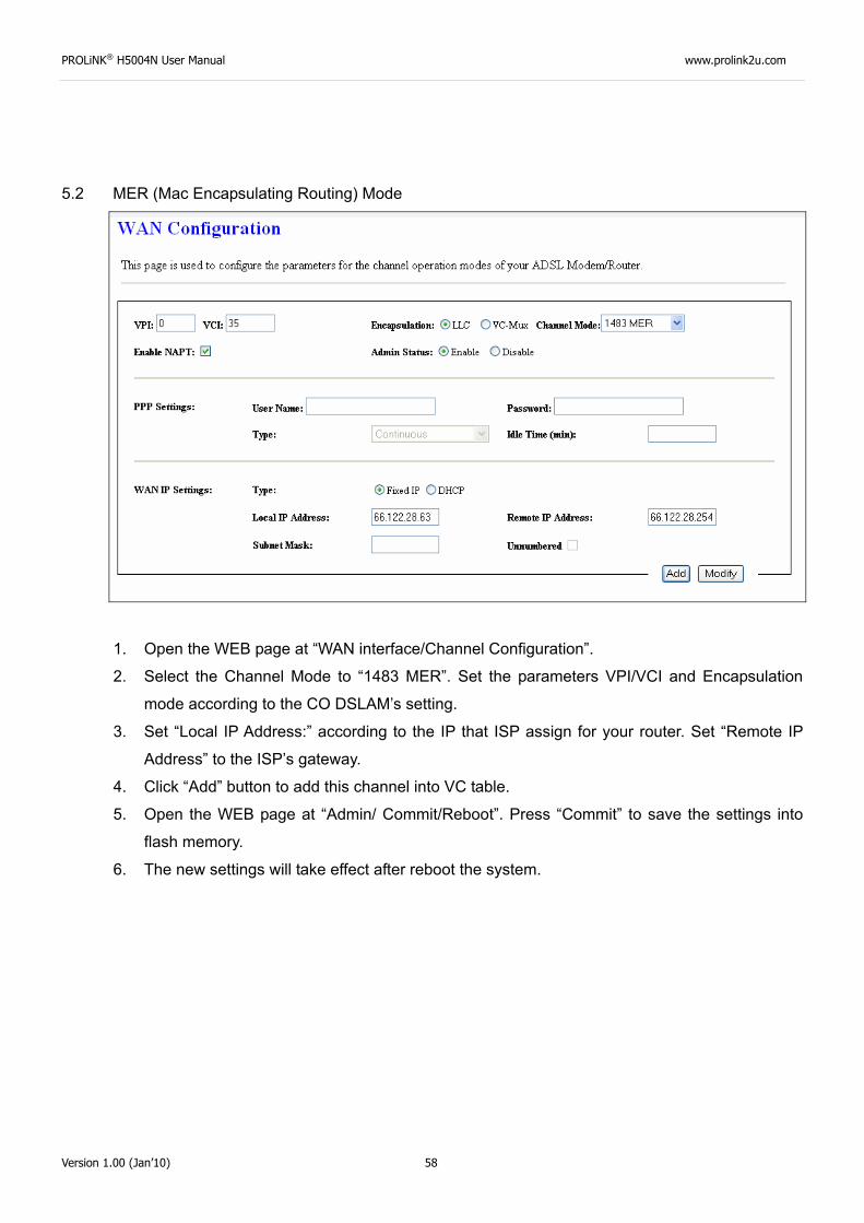
5.2 MER (Mac Encapsulating Routing) Mode
1. Open the WEB page at “WAN interface/Channel Configuration”.
2. Select the Channel Mode to “1483 MER”. Set the parameters VPI/VCI and Encapsulation
mode according to the CO DSLAM’s setting.
3. Set “Local IP Address:” according to the IP that ISP assign for your router. Set “Remote IP
Address” to the ISP’s gateway.
4. Click “Add” button to add this channel into VC table.
5. Open the WEB page at “Admin/ Commit/Reboot”. Press “Commit” to save the settings into
flash memory.
6. The new settings will take effect after reboot the system.
PROLiNK® H5004N User Manual www.prolink2u.com
Version 1.00 (Jan’10) 59
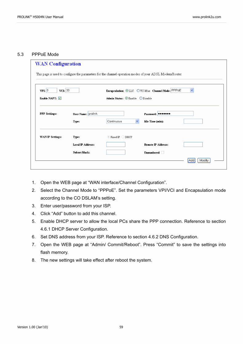
5.3 PPPoE Mode
1. Open the WEB page at “WAN interface/Channel Configuration”.
2. Select the Channel Mode to “PPPoE”. Set the parameters VPI/VCI and Encapsulation mode
according to the CO DSLAM’s setting.
3. Enter user/password from your ISP.
4. Click “Add” button to add this channel.
5. Enable DHCP server to allow the local PCs share the PPP connection. Reference to section
4.6.1 DHCP Server Configuration.
6. Set DNS address from your ISP. Reference to section 4.6.2 DNS Configuration.
7. Open the WEB page at “Admin/ Commit/Reboot”. Press “Commit” to save the settings into
flash memory.
8. The new settings will take effect after reboot the system.
PROLiNK® H5004N User Manual www.prolink2u.com
Version 1.00 (Jan’10) 60
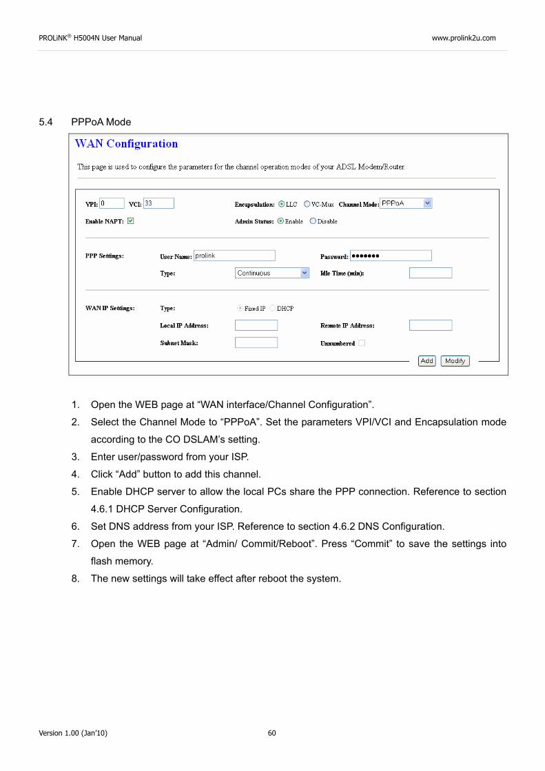
5.4 PPPoA Mode
1. Open the WEB page at “WAN interface/Channel Configuration”.
2. Select the Channel Mode to “PPPoA”. Set the parameters VPI/VCI and Encapsulation mode
according to the CO DSLAM’s setting.
3. Enter user/password from your ISP.
4. Click “Add” button to add this channel.
5. Enable DHCP server to allow the local PCs share the PPP connection. Reference to section
4.6.1 DHCP Server Configuration.
6. Set DNS address from your ISP. Reference to section 4.6.2 DNS Configuration.
7. Open the WEB page at “Admin/ Commit/Reboot”. Press “Commit” to save the settings into
flash memory.
8. The new settings will take effect after reboot the system.
PROLiNK® H5004N User Manual www.prolink2u.com
Version 1.00 (Jan’10) 61
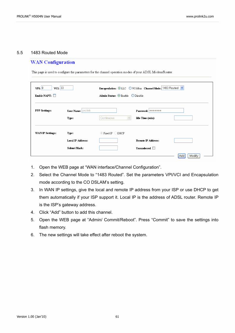
5.5 1483 Routed Mode
1. Open the WEB page at “WAN interface/Channel Configuration”.
2. Select the Channel Mode to “1483 Routed”. Set the parameters VPI/VCI and Encapsulation
mode according to the CO DSLAM’s setting.
3. In WAN IP settings, give the local and remote IP address from your ISP or use DHCP to get
them automatically if your ISP support it. Local IP is the address of ADSL router. Remote IP
is the ISP’s gateway address.
4. Click “Add” button to add this channel.
5. Open the WEB page at “Admin/ Commit/Reboot”. Press “Commit” to save the settings into
flash memory.
6. The new settings will take effect after reboot the system.
PROLiNK® H5004N User Manual www.prolink2u.com
Version 1.00 (Jan’10) 62
Chapter 6
Protocol Stacks
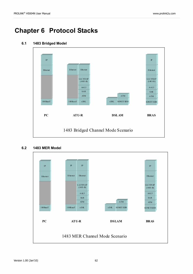
6.1 1483 Bridged Model
100BaseT
Ethernet
IP
100Ba seT
Ethernet
xDSL
ATM
SAR
AAL5
LLC /SNAP(1483-B)
Ethernet
xDSL SONET/SDH
ATM
SONET/SDH
ATM
SAR
AAL5
LLC/SNAP(1483-B )
Ethe rnet
IP
PC ATU-R DSLAM BRAS
1483 Bridged Channel Mode Scenario
6.2 1483 MER Model
1483 MER Channel Mode Scenario
100BaseT
Etherne t
IP
100B aseT
Et he rnet
xDSL
ATM
SAR
AAL5
L LC/SNAP(1483-B)
Etherne t
xDSL SONET/ SDH
ATM
SONE T/SDH
ATM
SAR
AAL5
LLC /SNAP(1483-B)
Etherne t
IP
PC ATU-R DSLAM BRAS
IP IP
PROLiNK® H5004N User Manual www.prolink2u.com
Version 1.00 (Jan’10) 63
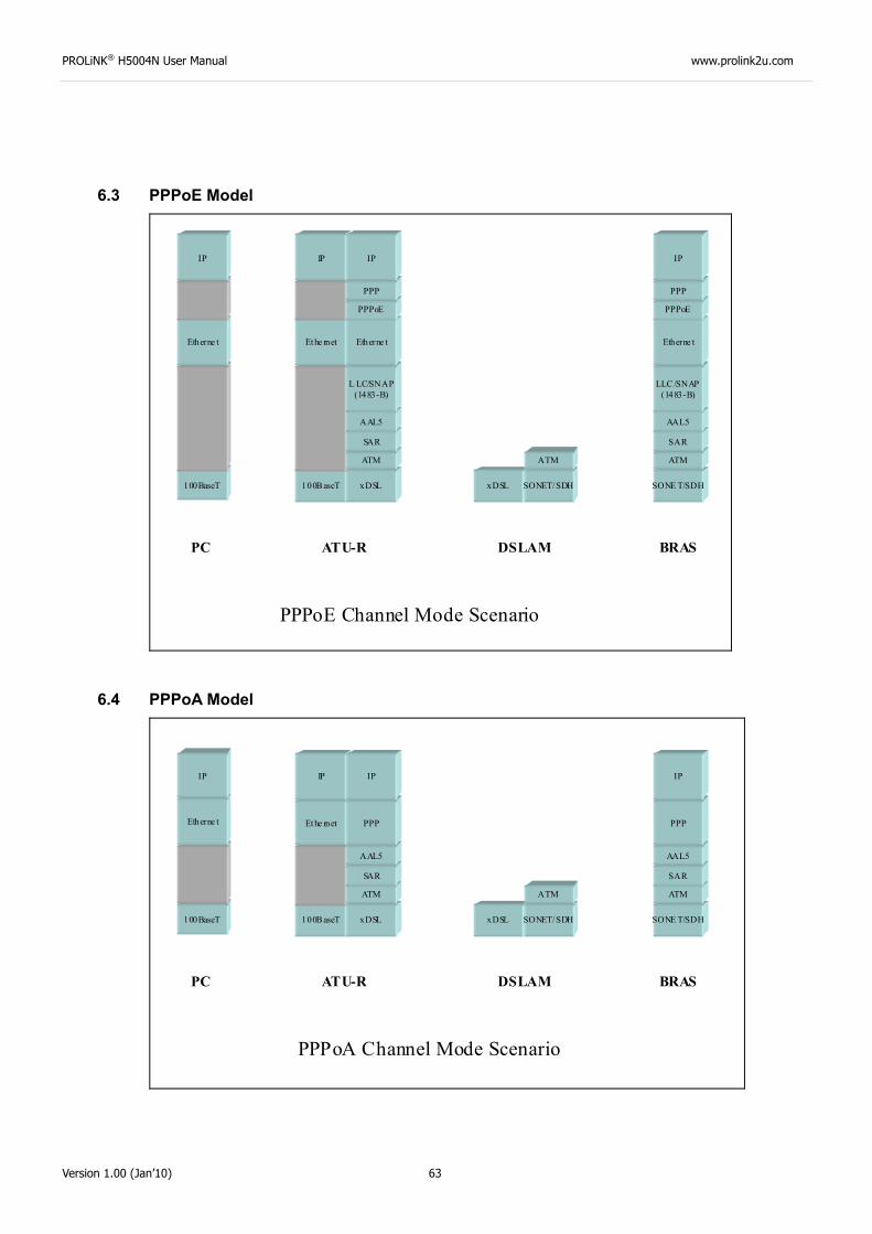
6.3 PPPoE Model
PPPoE Channel Mode Scenario
100BaseT
Etherne t
100B aseT
Ethe rnet
xDSL
ATM
SAR
AAL5
L LC/SNAP(1483-B)
Etherne t
xDSL SONET/SDH
ATM
SONE T/SDH
ATM
SAR
AAL5
LLC /SNAP(1483-B)
Etherne t
PC ATU-R DSLAM BRAS
PPPoE
PPP
IP
PPPoE
PPP
IP IPIP
6.4 PPPoA Model
PPPoA Channel Mode Scenario
100BaseT 100B aseT
Ethe rnet
xDSL
ATM
SAR
AAL5
xDSL SONET/SDH
ATM
SONE T/SDH
ATM
SAR
AAL5
PC ATU-R DSLAM BRAS
IP
PPP
IP
Etherne t
IP
PPP
IP
PROLiNK® H5004N User Manual www.prolink2u.com
Version 1.00 (Jan’10) 64
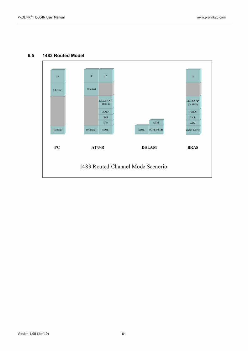
6.5 1483 Routed Model
1483 Routed Channel Mode Scenerio
100BaseT
Etherne t
IP
100B aseT
Ethe rnet
xDSL
ATM
SAR
AAL5
L LC/SNAP(1483-R)
xDSL SONET/SDH
ATM
SONE T/SDH
ATM
SAR
AAL5
LLC /SNAP(1483-R)
IP
PC ATU-R DSLAM BRAS
IP IP
PROLiNK® H5004N User Manual www.prolink2u.com
Version 1.00 (Jan’10) 65
Chapter 7
Questions & Answers
Q1 Why all LED indicators are off?
A1 • Check the connection between the power adaptor and the power socket.
• Check the power switch is on or not.
Q2 Why LAN LED is not lighting?
A2 • Check the connection between the ADSL modem and your computer, hub, or switch.
• Check the running status of your PC, hub, or switch, and ensure that they are working
normally.
Q3 Why ADSL LED is not lighting? A3 Check the connection between the ADSL “DSL” port and the wall jack.
Q4 Why cannot visit Internet with ADSL LED is on? A4 Ensure that the following information is correctly entered.
• VPI/VCI
• Username/password.
Q5 Why cannot open the Modem Web configuration page? A5 Follow below steps to check the communication between the computer and modem.
• Choose Start Run from the desktop, and ping 192.168.1.1 (the IP address of the modem).
• If the modem cannot be reached, please check following configuration:
- Type of the network cable
- Connection between the modem and computer
- TCP/IP configuration of you computer
Q6 How to load the default setting after incorrect configuration?
A6 • To restore the factory default, keep the device powered on and push a needle into the hole.
Press down the button about one second and then release.
• The default IP address and subnet mask of the modem are 192.168.1.1 and 255.255.255.0
respectively.
• User/password of super user: admin/admin
• User/password of common user: user/user
PROLiNK® H5004N User Manual www.prolink2u.com
Version 1.00 (Jan’10) 66
Chapter 8
Technical Support
REGISTER ONLINE FOR FREE WARRANTY.
FREE TECHNICAL SUPPORT HOTLINE: Monday to Friday, 9.00 am – 6.00 pm
(Closed on Saturdays, Sundays and Public Holidays)
• SINGAPORE : (65) 6357 0666
• MALAYSIA : (60) 3 8023 9151
• INDONESIA : (62) 21 3483 1777
WALK-IN SUPPORT: Monday to Friday, 9.00 am – 6.00 pm
(Closed on Saturdays, Sundays and Public Holidays)
• SINGAPORE FIDA INTERNATIONAL (S) PTE LTD
Block 16 Kallang Place, #06-02 Kallang Basin Industrial Estate, Singapore 339156.
• MALAYSIA FIDA SYSTEMS (M) SDN BHD
29 Jalan USJ 1/31, 47600 Subang Jaya, Selangor Darul Ehsan, Malaysia.
• INDONESIA PROLiNK INDONESIA
Jl. Cideng Barat No. 79 Jakarta Pusat 10150 Indonesia.
ONLINE TECHNICAL SUPPORT: • SINGAPORE : [email protected]
• MALAYSIA : [email protected]
• INDONESIA : [email protected]

PROLiNK is a trademark of Fida International (S) Pte Ltd and is manufactured under its authority. All other brands, products, services, logos and company names mentioned herein are trademarks of their respective owners. All specifications, designs and contents are subject to changes without prior notice. © Copyright 2009. PROLiNK all rights reserved.
Register Online For Your Product Warranty
www.prolink2u.com
SINGAPORE
FIDA INTERNATIONAL (S) PTE LTD
Block 16 Kallang Place, #06-02 Kallang Basin Industrial Estate, Singapore 339156.
Tel : (65) 6357 0668 Email : [email protected]
MALAYSIA FIDA SYSTEMS (M) SDN BHD
29 Jalan USJ 1/31, 47600 Subang Jaya, Selangor Darul Ehsan, Malaysia.
Tel : (60) 3 8024 9151 Email : [email protected]
INDONESIA PROLiNK INDONESIA
Jl. Cideng Barat No. 79 Jakarta Pusat 10150 Indonesia.
Tel : (62) 21 3483 1777 Email : [email protected]