Embed Size (px)
Citation preview

Dynamic Article LinksC<Soft Matter
Cite this: Soft Matter, 2011, 7, 1957
www.rsc.org/softmatter PAPER
Ultrathin film coatings of aligned cellulose nanocrystals from aconvective-shear assembly system and their surface mechanical properties
Ingrid Hoeger,a Orlando J. Rojas,*ab Kirill Efimenko,c Orlin D. Velevc and Steve S. Kelleya
Received 6th October 2010, Accepted 6th December 2010
DOI: 10.1039/c0sm01113d
Ultrathin films of aligned cellulose nanocrystals (CNCs) were deposited on solid supports by using
convective and shear forces. Compared to previous systems involving high electric or magnetic fields to
control the orientation of these rod-like natural nanoparticles, the proposed process of alignment was
very simple, inexpensive and with potential for scale up. The effect of concentration of CNC in aqueous
suspensions, type of solid support, relative humidity and rates of withdrawal of the deposition plate
were determined by using atomic force microscopy (AFM) and ellipsometry. The degree of orientation
was quantified from the number density of CNCs in leading angles by using image analyses. Also, the
contribution of shear and capillary forces on alignment parallel and normal to the withdrawal direction
was elucidated. The best alignment of CNCs in the withdrawal direction, favored by shear effects, was
achieved with gold and silica supports with a pre-adsorbed cationic polyelectrolyte layer and at a CNC
suspension concentration above 2.5% (w/w), below the critical concentration for chiral nematic phase
separation. Compared to the bare solid support, nanoindentation of the obtained coatings of ultrathin
films of oriented CNCs provided enhanced surface mechanical strength and wear resistance. A
transverse Young’s modulus, hardness and coefficient of friction of 8.3� 0.9 GPa, 0.38� 0.03 GPa and
0.51 � 0.23 GPa, respectively, were measured. Notably, the transverse Young’s modulus was found to
be in agreement with reported values predicted by molecular modeling and measured for single CNCs
by using atomic force microscopy.
1 Introduction
Cellulose nanocrystals (CNCs) have been used as a reinforcing
material in composites to improve their mechanical properties.
This is in part due to their relatively high intrinsic strength, high
aspect ratio and low density. The use of CNCs in high perfor-
mance coatings is attractive not only because of their properties
but also because they may provide a platform for fundamental
studies related to their assembly. Thin films of CNCs have been
produced by film casting,1 spin coating,1 and by the Langmuir–
Blodgett2 techniques. Recently, Rojas and coworkers also used
the Langmuir–Schaeffer surface lifting method to produce dense
layers of CNC on hydrophobic supports.3 When used in
composites, CNCs have been shown to affect markedly the
properties of the resultant materials, depending on the processing
conditions4 and their supramolecular organization.5
In general, the possibility to control the architecture of two-
and three-dimensional arrays of proteins, nanoparticles and
aForest Biomaterials, North Carolina State University Campus, Box 8005,Raleigh, North Carolina, 27695, USAbAalto University—School of Science and Technology, P.O. Box 16100,Espoo, 00076, Finland. E-mail: [email protected] and Biomolecular Engineering, North Carolina State University,Campus Box 7905, Raleigh, North Carolina, 27695, USA
This journal is ª The Royal Society of Chemistry 2011
nanomaterials is critical in applications related to biotechnology
(vaccines, diagnostics, etc.), biosensing, electronics, optics,
microengineering and electrocatalysts.5,6 The same can be stated
about the emerging possibility of CNCs as building blocks for
a broad range of structures. In such cases the additional benefit
of improved mechanical characteristics with aligned CNCs might
be realized.7
Above a certain concentration of CNC in aqueous suspensions
they self-assemble into chiral nematic structures.7 The orienta-
tion of the CNCs is slightly different at each of the nematic
planes due to rotation of the magnetic director about the
perpendicular cholesteric axis.7 Taking advantage of such
phenomena, several techniques have been used in attempts to
control the alignment of CNCs. These techniques include the
rotational shearing of gels8 and the application of intense
magnetic9,10 and electric fields.11–13 Recently, radially oriented
submonolayers of CNC were produced by spin-coating and the
response of myoblasts to the surfaces was assessed.14 The tech-
niques used for parallel alignment of CNCs are time consuming
and expensive, especially because of the requirement of high
(electric or magnetic) fields. Additionally, control over the
thickness of the final films has not been easily accomplished.
This work focuses on a new application of capillary and shear
forces to align CNCs in ultrathin films taking advantage of
Soft Matter, 2011, 7, 1957–1967 | 1957

systems to assemble particles onto solid supports. Among them,
a convective assembly system used to deposit arrays and coatings
of spherical colloids was found most useful. In this case the
organization of spherical particles occurs when the thickness of
a film is reduced due to solvent evaporation, and the particles in
the meniscus are pulled together by attractive capillary forces;
concurrently a flux of liquid toward the interface compensates
for the mass of liquid evaporated.15 In other systems a suspension
of particles has been dropped onto an angled stationary
substrate;16 while in others, the substrate has been placed verti-
cally into a vessel filled with a suspension of particles and with-
drawn at a constant speed.17,18 More recently, a droplet of
suspension has been trapped between two plates. The top plate
was set at a given angle and was moved with a linear motor.19 In
this latter study, several factors influenced the convective
assembly. The coating thickness and the organization of the
spherical particles in the film were found to depend on the
nanoparticle concentration,20–22 size,21 type of solid support,23
deposition speed,22 humidity24 and temperature.25
Due to potential benefits in coating applications, the
mechanical strength properties of nanocoatings with CNCs are
of interest. X-Ray diffraction,4,26 Raman spectroscopy27 and
AFM28 have been applied to investigate the mechanical moduli
of cellulosic structures, especially cellulose I in the cell wall and
cellulose nanocrystals. Most studies have been conducted on
fiber bundles,4,26 cast films27 and single CNCs.28 Attention has
mainly focused on the elastic properties along the axial direction
of the cellulose chain (Ea). However, only a few reports are
available on the transversal elastic modulus (ET), which include
the use of molecular modeling29,30 and AFM measurements with
single nanocrystals.28
Nanoindentation, on the other hand, has been widely used in
the determination of the elastic modulus of thin films created
from different engineered materials as well as from the cell wall
of cellulosic fibers.31–33 In nanoindentation tip displacement, the
load and time are continuously recorded and the Young’s
modulus and hardness can be calculated by using models such as
Oliver and Pharr’s.34
The goal of this study was to deposit ultrathin coatings con-
sisting of rod-like CNCs on solid supports and with controlled
orientation or alignment with the longer term objective to
modulate nanoscale architectures. These coatings are expected to
offer important advantages over conventional approaches
because of the expected mechanical strength, unique surface
performance and possible applications beyond coatings such as
those related to cell attachment and proliferation, tissue devel-
opment, etc. The process and conditions of CNC deposition were
first optimized for the formation of aligned nanoparticles. The
convective-shear assembly was found to be simple and fast and it
did not demand expensive equipment. Also, because of the
possibility of continuous operation it is expected to be suitable
for scaling up. The concentration of CNCs, withdrawal rate,
humidity and the type of solid support were varied to study their
effect on the properties of the resulting ultrathin films. Also,
multilayer films consisting of CNCs combined with adhesive
interlayers of poly(ethyleneimine) were manufactured using the
same approach. Key mechanical properties of the resulting
ultrathin films were determined, including the transverse
Young’s modulus, the hardness as well as the coefficient of
1958 | Soft Matter, 2011, 7, 1957–1967
friction and wear resistance. The possible surface strength
benefits that can be gained through the formation of aligned
CNC films are expected to broaden the possible applications of
such sustainable, biologically derived material.
2 Materials and methods
2.1 Materials
Ramie fibers from Stucken Melchers GmbH & Co., Germany,
were used in the production of cellulose nanocrystals. Micro-
crystalline cellulose (Avicel PH-101) from Fluka Chemical
Corporation was used in the preparation of regenerated cellu-
lose. Poly(ethyleneimine), PEI, from BASF Corporation was
employed to create a cationic surface layer on the mineral
substrate used as a solid support for the CNC films. 50%
4-methylmorpholine N-oxide and dimethyl sulfoxide were
purchased from Sigma-Aldrich. Silicon wafers, 350–600 mm
thickness and with no orientation, were purchase from Wafer
World, Inc. (West Palm Beach, FL). Gold slides (100 � 300 �0.04000 with a coating of 50 �A Ti and 1000 �A Au), mica sheets
(grade V5, 10� 40 mm; thickness 0.23 mm) and glass microscope
slides (300 � 100 � 1.0 mm) were acquired from EMF-Corp
(Ithaca, NY), Ted Pella, Inc. (Redding, CA) and Fisher (Pitts-
burgh, PA), respectively.
2.2 Cellulose nanocrystals
Ramie fibers were purified via soxhlet extraction, then hydro-
lyzed with 65% sulfuric acid at 55 �C for 30 min under continuous
stirring; the resulting suspension was filtered through a sintered
Buchner funnel, washed with deionized water and recovered by
subsequent centrifugations at 10 000 rpm (10 �C) for 10 min
each. Finally the resulting suspension was dialyzed against
deionized water and then against Milli-Q water for a few weeks;
the resulting master stock suspension was stored at 4 �C until use.
The dimensions of the CNCs were 185 � 25 and 6.5 � 0.7 nm in
length and width, respectively, as determined from TEM images,
the crystallinity index was 88% as measured by X-ray diffraction
and the surface charge was 0.30 e nm�2 as determined by the
concentration of sulfate groups on the surface (0.76%) from
sulfur elemental analyses.3
2.3 Films of regenerated cellulose
Regenerated films of cellulose were prepared following a tech-
nique reported earlier.35 Briefly, microcrystalline cellulose was
dissolved in 4-methylmorpholine N-oxide and dimethyl sulfoxide
to a final concentration of 5 mg ml�1. This solution was spin
coated (Laurell Technologies model WS-400A-6NPP) at 5000
rpm for 40 s onto a silicon wafer with pre-adsorbed PEI. The
films were dried in an oven at 80 �C for 2 h and then hydrated for
4 h in Milli-Q water. This procedure was repeated at least 5 times,
in order to obtain films of given thicknesses for further studies
with nanoindentation.
2.4 CNC films from convective-shear assembly
A schematic illustration of the convective-shear assembly setup
used for the production of coating films of CNCs is shown in
This journal is ª The Royal Society of Chemistry 2011

Fig. 1 Experimental setup for assembly and deposition showing the CNC suspension, solid support, withdrawal plate and three-phase line (a) and
AFM top view of cellulose nanocrystals assembled on solid supports using a withdrawal plate operated at 8.4 cm h�1 (b and c). The 2.5 � 2.5 mm AFM
height images in panel (b) were obtained at the center of the film assembled on gold (upper image) and on mica (bottom image). The corresponding black
and white processed images obtained after partitioning and filtering the AFM scans of the nanocrystal film are shown in panel (c). Panel (d) shows the
respective histograms for the number % of aligned CNCs in leading angles using as a reference the withdrawal direction.
Fig. 1a. It included a solid support and a moving or withdrawal
plate. The gold and silica substrates were cleaned with a solution
consisting of sulfuric acid (70%) and hydrogen peroxide (30%)
for 20 min followed by a thorough rinse with deionized and Milli-
Q water. In the production of cationic silica, silicon wafers were
treated with a 500 ppm PEI solution for 20 min, followed by
rinsing with Milli-Q water. The respective substrate was placed in
the horizontal stage of the assembly device (Fig. 1a) and CNC
suspension was added between the inclined plate and the
substrate. Two parameters were kept constant, namely, the
volume of suspension used, 10 ml, and the angle of inclination of
the withdrawal plate, 12� with respect to the substrate. The three-
phase line was formed at the interphase where the front of the
suspension, the solid substrate and the air phase meet, as indi-
cated in Fig. 1a. The solid support was fixed on the stage and the
glass slide moved at a constant speed. The withdraw velocity was
precisely controlled by attaching the inclined plate to the syringe
pump motor assembly (NE 500 New Era pump system Inc.,
Wantaugh, NY). After the deposition was completed, the films
were allowed to air-dry in a laminar flow cabinet. For multilayer
films, silicon wafers were first treated with the PEI solution by
immersion in a solution of 500 ppm for 20 min, then rinsed with
Milli-Q water and dried with nitrogen nozzle. CNCs were then
deposited with the setup shown in Fig. 1a and the procedure was
repeated as many times as required to obtain targeted number of
layers. In the case of nanoindentation studies 10 deposition
cycles were carried out.
2.5 Atomic Force Microscope (AFM)
An AFM XE 100 from Park Systems (Santa Clara, CA) was used
in a non-contact mode to obtain topographic images of the
supports before and after CNC deposition. A pyramidal silicon
tip with a radius less than 10 nm and with an aluminium coating
This journal is ª The Royal Society of Chemistry 2011
on the backside (Park Systems, Santa Clara, CA) was used with
an applied constant force of 42 N m�1 and 330 KHz frequency.
The XE-100 scanner configuration allowed simultaneous
recording of X–Y and Z signals. The X–Y scanner moved the
sample in the horizontal direction and the Z scanner traced the
topography of the sample moving the cantilever in the vertical
direction. The coordinate information allowed interpretation of
the orientation direction of the CNCs in the images. At least
three different films, at three different positions, were imaged for
each deposition condition used. The images were analyzed using
the XEI software, and only a flatten process of one regression
order was used to correct the slope of the tip/sample interaction.
Scans of different sizes were obtained but only the 2.5 � 2.5 mm
sizes are reported here, unless stated otherwise.
2.6 Ellipsometry
A variable angle spectroscopic ellipsometer (VASE, J. A.
Woollam Co., Inc.) with a wide spectral range capability of
190–1100 nm was used to measure the film thickness. Data were
collected at different angles of incidence (55, 60, 65, 70 and 75�),
between 300 and 800 nm. The ellipsometric amplitude ratio, J,
and the phase difference, D, data were fit using a Cauchy model,36
assuming a refractive index of 1.56 for cellulose.37 In order to
increase the fitting accuracy the Bruggeman model of the effec-
tive medium approximation (EMA) layer38 was employed. This
approximation allowed proper film thickness analysis by incor-
porating air as an integral part of the ultrathin film and to
consider the effect of roughness.
2.7 Degree of CNC alignment
As explained before, the convective-shear assembly setup used to
align the CNCs within thin films deposited from aqueous
Soft Matter, 2011, 7, 1957–1967 | 1959

suspensions is shown in Fig. 1. After obtaining AFM images of
the resultant films a Matlab code was used to determine the
degree of CNC alignment. This code used AFM topography
images by performing a grain partition and filtering the sizes of
the grains. The angles of leading edge or the long axis of the
CNCs were determined in a polar plot between 0 and 90� with
respect to the withdrawal direction and the degree of CNC
alignment was defined as the number % of CNCs in the angle
range between 0 and 20� in the withdrawal direction. Consid-
ering symmetry conditions for the angles between 0 and 90, and
90 and 180� the respective number % of CNCs counted at the
given angle were added to the number collected for the 0 to 90�
angle range. The histograms (number % of CNCs) for a given
angle range were obtained. Typically, more than 300 CNCs were
counted in each image analysis and at least 3 different locations,
from 3 different films, were analyzed for each condition.
2.8 Nanoindentation
A TI 900 TriboIndenter from Hysitron Inc. (Minneapolis, MN)
equipped with a Berkovich three-sided pyramidal diamond tip of
50 nm radius of curvature was used to measure the mechanical
properties of multilayers of CNC assemblies. The apparatus used
a load of 3 mN and a displacement resolution of 4 nm. The lateral
positioning accuracy is reported to be �20 nm, according to the
manufacturer.
For the indentations the peak load force was controlled
between 5 and 35 mN with a total 15 seconds testing time per load
(5 s loading, 5 s hold and 5 s unloading). The unloading load–
depth curve was used to analyze the nanoindents and fitting of
the data using the Oliver–Pharr approach34 to obtain the hard-
ness and Young’s modulus. The friction coefficient was measured
at four different load forces (10, 15, 20 and 25 mN) with a 1 mm
scratch length. In the wear tests four different load forces (10, 15,
20 and 25 mN) were applied for four passes in a 5 � 5 mm scan
area. Indentation in wear tests was followed by imaging a larger
size area (10 � 10 mm) that contained the scratched region. The
peak load forces were selected so that the indentation depth
remained less than 20% of the film thickness, to prevent the
influence of the substrate in the measurement of the mechanical
properties.39 Three different points for at least three different
samples were tested to determine the average values reported.
3 Results and discussion
CNC films obtained by cast evaporation and studied under an
optical microscopy with cross-polarized light show nanocrystal
patterns due to their assembly in aqueous suspensions at given
concentrations.7 The so-called fingerprint patterns of the chole-
steric texture can be distinguished by their characteristic alter-
nating light and dark bands which represent the rotation of the
nematic director.40 Several parameters affect the chiral nematic
phase of CNC, such as ionic strength, temperature, concentra-
tion and external forces.41 It has been observed that the behavior
of CNCs in aqueous suspensions under shear depends on the
ratio of two Leslie viscosities, either flow-aligning, where the
director adopts a stable position during flow, or tumbling, where
the director has no stable position.42 Overall, it is expected that
by controlling shear forces, or electric and magnetic fields, it is
1960 | Soft Matter, 2011, 7, 1957–1967
possible to change the rotation of the nematic director to achieve
ordered structures in 2-D assemblies. As such, the effects of shear
and capillary forces on CNC alignment are discussed further.
3.1 Alignment of CNCs by shear forces
The convective-shear assembly setup was used to organize CNCs
with different degrees of alignment with respect to the with-
drawal direction (Fig. 1a) and the degree of alignment of CNCs is
discussed in terms of the number % of CNCs aligned in the 0–20�
of the withdrawal direction. Two extreme, illustrative results are
provided in Fig. 1b–d. The upper panels of Fig. 1b and c show an
ultrathin film of cellulose nanocrystals deposited on a gold
substrate that were preferentially oriented parallel to the with-
drawal direction. The respective histograms indicated that ca. 70
number % of CNCs were parallel to the withdrawal direction (see
polar histogram in Fig. 1d, top). The bottom panels of Fig. 1b
and c show that the cellulose nanocrystals coated onto a mica
surface were oriented mainly normal to the withdrawal direction
(only 5% of CNCs parallel to the withdrawal direction, see polar
histogram in Fig. 1d, bottom).
The effects of the substrate type and the concentration of
cellulose nanocrystals in aqueous suspension as well as the
withdrawal speed in the convective-shear assembly setup were
investigated. Also considered were the influence of the relative
humidity of the surrounding air, and the resulting changes in the
drying rate. The primary film parameters that were evaluated
included the thickness of the CNC layers, surface roughness and
degree of CNC alignment.
3.1.1 Effect of solid support. To evaluate the effect of the
solid support on the degree of CNC alignment, five different
substrates were tested, namely, mica sheets with a high negative
charge density; less negatively charged silica wafers; positively
charged silicon wafers with pre-adsorbed polyethyleneimine
(PEI), and high and low surface energy gold-based slides. The
low surface energy substrates were prepared by reacting
alkylthiol with freshly cleaned gold. It is worth noting that the
CNCs used in this study were produced by sulfuric acid hydro-
lysis; consequently they were negatively charged due to the
presence of residual sulfate ester groups.43
Different degrees of alignment were obtained in the different
regions of the film, as determined by AFM and image processing.
At the edge of the film, i.e., at the beginning of the deposition
process, the CNCs were more randomly distributed compared to
areas where the film was well developed (after reaching stable
conditions for nanoparticle deposition). This behavior was more
pronounced on the mica substrate. Therefore, the areas of the
films that were used in the determination of the degree of
alignment (see for example Table 1) corresponded to average
values measured in the middle section, at three-fourths the total
film length and close to the end edge of the film.
The CNC films shown in Fig. 2 on mica (a) and silica (c), i.e.,
substrates with same charge type than that of the CNCs were less
aligned than those deposited on gold (b) or on silica with pre-
adsorbed PEI (d). One would expect that the CNCs alignment
would have been more pronounced on the negatively charged
substrates, compared to the positively charged one (PEI). In fact,
it has been reported that ordered arrays of colloidal spheres on
This journal is ª The Royal Society of Chemistry 2011

Table 1 Percentage of CNCs aligned in the 0–20� angle range with thewithdrawal direction as reference after utilizing solid supports ina convective-shear assembly setup (Fig. 1a). The % CNC numberdistribution was obtained from image analysis and respective polarhistograms (see Fig. 1d)
Substrate% CNC alignmentbetween 0 and 20�
Silica 31 � 20Mica 27 � 19Gold 55 � 16Silica with pre-adsorbed PEI 44 � 12
solid supports are achieved when a higher mobility of the
particles is favored, for example, when electrostatic repulsion
forces for systems of equal electrostatic charges are present in the
film before the solvent evaporates.23
In the case of gold surfaces (Fig. 2b) the shear forces appeared
to be determinant in CNC alignment. On the other hand, layers
of CNCs were difficult to form on the hydrophobic substrates,
using same operation conditions, likely due to the reduced
wetting by the aqueous phase. The fact that different substrates
produced different degrees of CNC alignment highlights the
influence of their charge and surface energy.
Overall, the induced orientation of CNCs is determined by
a complex balance of forces, mainly, hydrodynamic (shear and
drag), Brownian, surface tension (capillary forces) and electro-
static interactions (between the negatively charged CNCs and
Fig. 2 AFM 2.5 � 2.5 mm height images for four different substrates: mica (a
deposited from 2.5% CNC aqueous suspension at a withdrawal speed of 8.4
This journal is ª The Royal Society of Chemistry 2011
between the CNCs and the substrate). Thus, it appears that the
poor alignment of CNC observed in the case of the negatively
charged solid support can be explained by the dominant and
counterbalancing effects of shear and capillary forces acting
normal and parallel to the three phase contact line, respectively.
Two dimensionless numbers are useful to quantify the relative
effect of capillary and shear forces. These are the capillary
number, Ca ¼ mW0
s, where s is the surface tension, m the
viscosity and W0 withdrawal velocity (shear) and a fluid property
number, m which is defined by m ¼�
s3r
m4g
�1=2
which also includes
the density and gravitational force, g. No attempt was made here
to fully characterize the system by using Ca and m since the
density r and viscosity of the films are expected to vary during
deposition. Since CNC suspensions are shear-thinning Ca
depends on the withdrawal rates in a complex way. However,
average capillary numbers were determined to be relatively small,
between ca. 0.3 � 10�4 and 1 � 10�4 for the highest and lowest
withdrawal rates, respectively. Finally, related effects of
concentration gradients are relevant because the evaporation at
the back end of the film leads to a higher CNC concentration.
This could translate into a better alignment in the withdrawal
direction, from the middle towards the end section of the film.
3.1.2 Multilayer films. Multilayer films of different thick-
nesses can be obtained by adjusting the CNC concentration and
withdrawal rate. As explained in the ‘‘Materials’’ section, TEM
), gold (b), silica (c), and silica with pre-adsorbed PEI (d). The films were
cm h�1.
Soft Matter, 2011, 7, 1957–1967 | 1961

imaging indicated a width of 6.5 � 0.7 nm for individual CNC
particles which would also correspond to the thickness of a CNC
monolayer film. Typically, film thicknesses after convective-
shear deposition under the conditions used in films reported in
Fig. 3b and d, using cationic substrates, were equivalent to
ca. three CNC layers. CNC films obtained by the Langmuir–
Schaeffer technique, as reported in our earlier publication,3 were
subjected to AFM imaging and found not to exhibit any
particular alignment (Fig. 3a and c). Relative to the vertical
direction (vertical axis taken as zero degrees) the CNC number
distribution of the respective leading angles was determined to be
12% (0–20�), 14% (20–40�), 23% (40–60�) and 51% (60–90�). On
the other hand, films obtained by using the convective-shear
assembly setup showed a distinctive alignment of CNCs, with
70% of the particles aligned in the 0–20� angle range. The better
alignment obtained in the latter case can be explained by
Fig. 3 1 mm� 1 mm AFM height (a and b) and respective phase images (c and
c) and the convective-shear assembly setup using silica substrates with pre-ad
vertical direction was parallel to the withdrawal direction. A withdrawal spee
1962 | Soft Matter, 2011, 7, 1957–1967
attractive electrostatic forces that helped to pin the first CNC
layer onto the solid support while repulsion forces between the
contiguous CNC facilitated better mobility and therefore better
alignment under the dominant shear. Also, it is possible that
pinning down the first layer could create higher shear forces that
improved organization or alignment of CNCs above it. These
hypotheses are supported by the observed effect of initial CNC
concentration (see Fig. 4): monolayer films made at low
concentrations exhibited poor alignment while multilayer films
displayed better alignment. Other considerations are discussed
further in this discussion.
3.1.3 Effect of suspension concentration on CNC assembly.
Generally, the thickness of films obtained by convective assembly
of spherical particles can be controlled by varying the solids
concentration in the casting suspension and the withdrawal
d) of CNC films produced with the Langmuir–Schaeffer technique (a and
sorbed PEI (b and d). Images b and d are placed in such a way that the
d of 8.4 cm h�1 and 2.5% CNC concentration were used.
This journal is ª The Royal Society of Chemistry 2011

Fig. 4 AFM 2.5 mm � 2.5 mm height images of ultrathin films of CNC obtained from aqueous suspensions of different concentrations deposited on
silica substrates with pre-adsorbed PEI by using a convective-shear assembly setup operated at a withdrawal speed of 8.4 cm h�1. CNC concentrations
used were 0.1 (a), 0.5 (b), 1 (c), 2.5 (d) and 4.5% (e).
rates.20–22 In fact, CNC film thicknesses were observed to increase
with CNC concentration, for a given withdrawal rate (see Fig. 4
and Table 2). Roughly, a CNC monolayer was formed at
concentrations below 1% while multilayer films were produced
at concentrations above 1% (see ellipsometric thicknesses in
Table 2).
Geometrical hindrance can account for the low orientation of
CNCs at the concentrations below 1% reported in Table 2, in
agreement with observations made in CNC suspensions.4 The
shear rate during deposition from 0.1% CNC suspension was
calculated to be ca. 2.5 s�1; similar low shear fields favored more
random orientation of CNCs in diluted aqueous media.42 For
concentrations above 1% (w/w) the alignment of CNCs in the
withdrawal direction was clearly increased with concentration, as
can be observed in Fig. 4 and Table 2.
Table 2 Effect of aqueous suspension CNC concentration on the ellip-sometric thickness and CNC alignment of ultrathin films. CNC filmswere deposited on silica with pre-adsorbed PEI. As a reference it is notedthat the TEM thickness of a single CNC was measured to be 6.5 � 1 nm
Concentration/%w/w
Ellipsometricthickness/nm
% CNC alignedbetween 0 and 20�
0.1 7.4 � 0.5 33 � 70.5 9.4 � 0.8 20 � 71.0 20.8 � 0.4 33 � 82.5 37.8 � 0.8 44 � 124.5 63.5 � 7.4 68 � 9
This journal is ª The Royal Society of Chemistry 2011
3.1.4 Effect of withdrawal rate and relative humidity on CNC
assembly. Under the conditions of CNC assembly used, the
alignment occurred mainly in the direction normal to the three
phase contact line, as shown in Fig. 1, i.e., in the direction
parallel to the withdrawal axis. This fact supports the hypothesis
that shear forces were leading factors for CNC alignment, as
demonstrated in the case of rod-like Tobacco Mosaic virus
studied by Velev et al.44 In order to investigate this issue further
the withdrawal speed of the upper plate was varied. It was
observed that at low withdrawal rates the CNC alignment was
first improved with the withdrawal rate (see Table 3). However,
maximum order was achieved at intermediate shear rates while at
the highest withdrawal rates tested (21–25.2 cm h�1) the CNCs
became less ordered.
It is proposed that as the liquid front was pulled in the with-
drawal direction by surface tension forces and as the withdrawal
Table 3 Thickness and degree of alignment of CNCs in ultrathin filmsdeposited at different withdrawal rates on silica substrates withpre-adsorbed PEI (CNC concentration in aqueous suspension was 2.5%)
Withdrawalrate/cm h�1
Ellipsometricthickness/nm
CNC aligned between0 and �20� (%)
4.2 85.4 � 2 41 � 196.3 40.6 � 1.7 57 � 78.4 37.8 � 1 44 � 1216.8 19.0 � 2 44 � 2021.0 19. 2 � 2 37 � 1625.2 16.7 � 6.7 38 � 10
Soft Matter, 2011, 7, 1957–1967 | 1963
rate increased the thickness of the resulting film decreased,
thereby shifting the architecture of the film from a multiple layer
towards a monolayer. At the highest shear rates only one or two
layers were deposited. As these layers were bound irreversibly to
the cationic substrate, they were randomly oriented (low degree
of alignment) while in thicker films the overlying layers were
generally better oriented. These observations are in agreement
with the previous discussion for the effect of CNC concentration
on particle alignment.
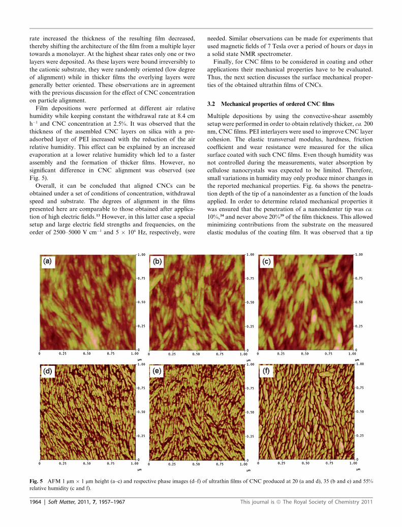
Film depositions were performed at different air relative
humidity while keeping constant the withdrawal rate at 8.4 cm
h�1 and CNC concentration at 2.5%. It was observed that the
thickness of the assembled CNC layers on silica with a pre-
adsorbed layer of PEI increased with the reduction of the air
relative humidity. This effect can be explained by an increased
evaporation at a lower relative humidity which led to a faster
assembly and the formation of thicker films. However, no
significant difference in CNC alignment was observed (see
Fig. 5).
Overall, it can be concluded that aligned CNCs can be
obtained under a set of conditions of concentration, withdrawal
speed and substrate. The degrees of alignment in the films
presented here are comparable to those obtained after applica-
tion of high electric fields.13 However, in this latter case a special
setup and large electric field strengths and frequencies, on the
order of 2500–5000 V cm�1 and 5 � 106 Hz, respectively, were
Fig. 5 AFM 1 mm � 1 mm height (a–c) and respective phase images (d–f) of
relative humidity (c and f).
1964 | Soft Matter, 2011, 7, 1957–1967
needed. Similar observations can be made for experiments that
used magnetic fields of 7 Tesla over a period of hours or days in
a solid state NMR spectrometer.
Finally, for CNC films to be considered in coating and other
applications their mechanical properties have to be evaluated.
Thus, the next section discusses the surface mechanical proper-
ties of the obtained ultrathin films of CNCs.
3.2 Mechanical properties of ordered CNC films
Multiple depositions by using the convective-shear assembly
setup were performed in order to obtain relatively thicker, ca. 200
nm, CNC films. PEI interlayers were used to improve CNC layer
cohesion. The elastic transversal modulus, hardness, friction
coefficient and wear resistance were measured for the silica
surface coated with such CNC films. Even though humidity was
not controlled during the measurements, water absorption by
cellulose nanocrystals was expected to be limited. Therefore,
small variations in humidity may only produce minor changes in
the reported mechanical properties. Fig. 6a shows the penetra-
tion depth of the tip of a nanoindenter as a function of the loads
applied. In order to determine related mechanical properties it
was ensured that the penetration of a nanoindenter tip was ca.
10%,34 and never above 20%39 of the film thickness. This allowed
minimizing contributions from the substrate on the measured
elastic modulus of the coating film. It was observed that a tip
ultrathin films of CNC produced at 20 (a and d), 35 (b and e) and 55%
This journal is ª The Royal Society of Chemistry 2011

Fig. 6 Mechanical properties of surfaces as a function of force load: penetration depth during nanoindentation at various loads (a), elastic transversal
modulus (b) and hardness (c). The systems studied consisted of CNC-PEI films (:) and references of silica (-) and spin coated regenerated cellulose
(C). The vertical dash lines correspond to 20% film penetration for regenerated cellulose (left dashed line) and for CNC-PEI multilayer films (right
dashed line).
Fig. 7 Friction coefficient for coating films composed of CNCs with PEI
interlayers measured at different loads (:). Friction coefficients for the
references bare silica substrate (-) and regenerated cellulose (C) are
also included.
penetration equivalent to 20% in a typical CNC film was reached
at a normal force of about 25 mN.
3.2.1 Transverse elastic modulus of CNC films. It was found
that the elastic transversal modulus of CNC films (8.3� 0.9 GPa,
Fig. 6b) was of the same order of magnitude than values pre-
dicted by molecular modeling and also recently reported for the
single CNC measured using AFM, i.e., 11–57 GPa29,30,45 and 18–
50 GPa (Tunicate CNCs),28 respectively. The reason for the
comparatively lower modulus in the present study might be
related to the fact that multilayer structures intercalated with PEI
layers were the ones probed as opposed to the pure CNC in van
der Waals contact which is assumed in molecular modeling or in
AFM measurement with a single CNC. The hardness of CNC
films was found to be in the range of 0.38 � 0.03 GPa (see
Fig. 6c). To our knowledge no values for the hardness of CNC
films are available in the literature. Published values for the
hardness of wood (0.358 and 0.387 GPa)32 and microcrystalline
cellulose (0.01–1 GPa)46 have been reported.
The mechanical properties for films of regenerated cellulose
obtained by spin coating having an elastic transversal modulus
and a hardness of 13.1 � 2.3 GPa and 0.50 � 0.1 GPa, respec-
tively, did not differ substantially from those measured in
oriented CNC films. The comparatively high values for the
elastic transverse modulus for films of regenerated cellulose can
be explained by the possibility that the axes of cellulose chains lie
both parallel and normal to the silica surface while in the case of
films with CNCs chain axes lie parallel to surface. A more
pronounced difference in the mechanical properties would be
found if these films were tested in the axial direction since the
axial elastic modulus of CNCs is distinctively high, 110–200 GPa,
compared to values expected for regenerated cellulose.28,47
While in the case of cellulose films the transverse elastic
modulus and the hardness reached somewhat constant values
with the penetration of the probe, this was not the case for the
reference bare silica surface: the elastic modulus was observed to
increase with penetration depth in the range tested. For silica
a minimum penetration depth of 20 nm was calculated to be
needed in order for the respective mechanical properties to
become independent of the depth of probing,39 a situation that
was not ensured with the normal loads that were applied. In fact,
This journal is ª The Royal Society of Chemistry 2011
the loads applied produced only a tip penetration in silica of only
5 nm. As a reference, 172 and 12.75 GPa for the elastic modulus
and a hardness, respectively, have been reported for silica.39
3.2.2 Friction and wear resistance of CNC films. Coatings are
usually applied to improve the material performance, including
tribological, electrical, optical, electronic, chemical or magnetic
functions.48 Composite tribological coatings have been designed
primarily to have a specific friction behavior and a high wear
resistance.48 Controlling the friction of a coating may be bene-
ficial in a number of applications; for example, in the automobile
and aeronautic industries the reduction of friction often means
a reduction in energy consumption.48 On the other hand, wear
determines the lifetime of materials and it is critical in many
processes.49 Materials commonly used for related coatings
include nitrides, carbides, oxides and their combinations, as well
as molybdenum disulfide, diamond-like carbon and diamond.
Recently mineral nanocrystalline multilayer coatings with supe-
rior mechanical and tribological properties were developed.50
Soft Matter, 2011, 7, 1957–1967 | 1965
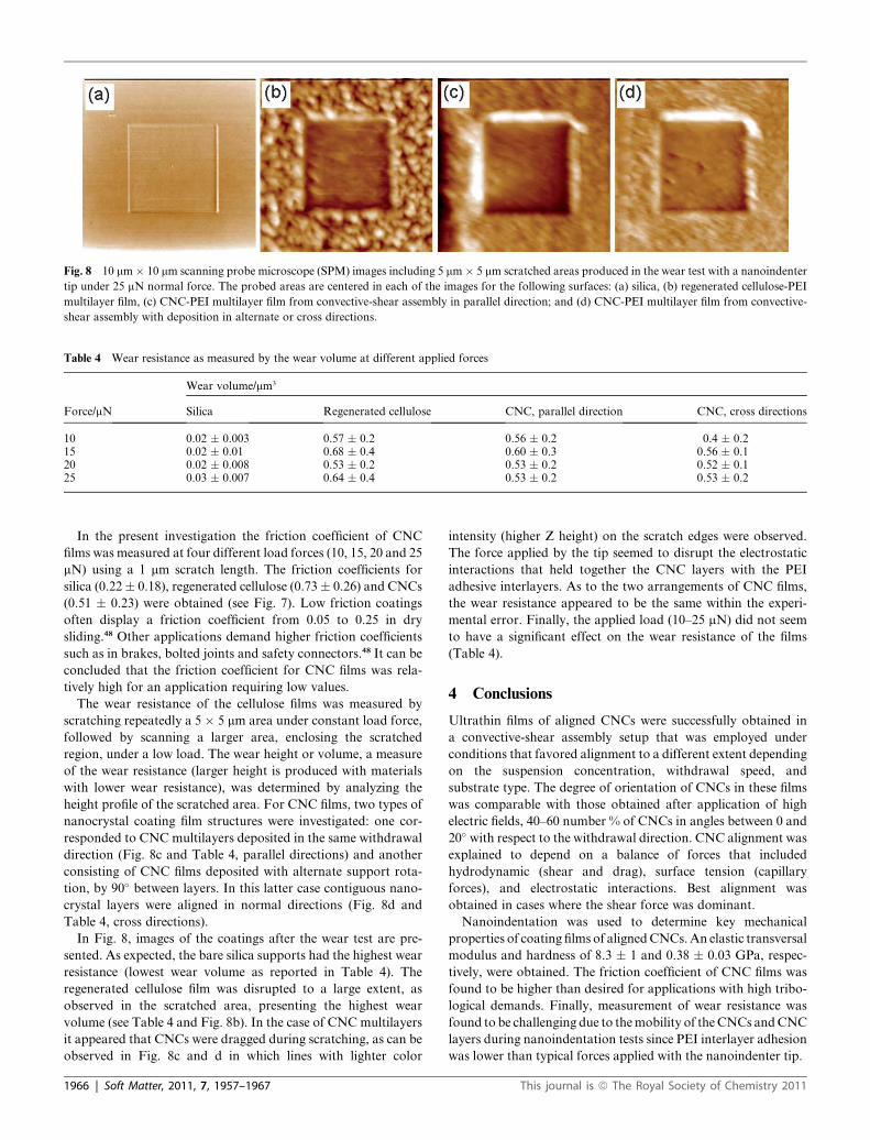
Fig. 8 10 mm� 10 mm scanning probe microscope (SPM) images including 5 mm� 5 mm scratched areas produced in the wear test with a nanoindenter
tip under 25 mN normal force. The probed areas are centered in each of the images for the following surfaces: (a) silica, (b) regenerated cellulose-PEI
multilayer film, (c) CNC-PEI multilayer film from convective-shear assembly in parallel direction; and (d) CNC-PEI multilayer film from convective-
shear assembly with deposition in alternate or cross directions.
Table 4 Wear resistance as measured by the wear volume at different applied forces
Force/mN
Wear volume/mm3
Silica Regenerated cellulose CNC, parallel direction CNC, cross directions
10 0.02 � 0.003 0.57 � 0.2 0.56 � 0.2 0.4 � 0.215 0.02 � 0.01 0.68 � 0.4 0.60 � 0.3 0.56 � 0.120 0.02 � 0.008 0.53 � 0.2 0.53 � 0.2 0.52 � 0.125 0.03 � 0.007 0.64 � 0.4 0.53 � 0.2 0.53 � 0.2
In the present investigation the friction coefficient of CNC
films was measured at four different load forces (10, 15, 20 and 25
mN) using a 1 mm scratch length. The friction coefficients for
silica (0.22� 0.18), regenerated cellulose (0.73� 0.26) and CNCs
(0.51 � 0.23) were obtained (see Fig. 7). Low friction coatings
often display a friction coefficient from 0.05 to 0.25 in dry
sliding.48 Other applications demand higher friction coefficients
such as in brakes, bolted joints and safety connectors.48 It can be
concluded that the friction coefficient for CNC films was rela-
tively high for an application requiring low values.
The wear resistance of the cellulose films was measured by
scratching repeatedly a 5 � 5 mm area under constant load force,
followed by scanning a larger area, enclosing the scratched
region, under a low load. The wear height or volume, a measure
of the wear resistance (larger height is produced with materials
with lower wear resistance), was determined by analyzing the
height profile of the scratched area. For CNC films, two types of
nanocrystal coating film structures were investigated: one cor-
responded to CNC multilayers deposited in the same withdrawal
direction (Fig. 8c and Table 4, parallel directions) and another
consisting of CNC films deposited with alternate support rota-
tion, by 90� between layers. In this latter case contiguous nano-
crystal layers were aligned in normal directions (Fig. 8d and
Table 4, cross directions).
In Fig. 8, images of the coatings after the wear test are pre-
sented. As expected, the bare silica supports had the highest wear
resistance (lowest wear volume as reported in Table 4). The
regenerated cellulose film was disrupted to a large extent, as
observed in the scratched area, presenting the highest wear
volume (see Table 4 and Fig. 8b). In the case of CNC multilayers
it appeared that CNCs were dragged during scratching, as can be
observed in Fig. 8c and d in which lines with lighter color
1966 | Soft Matter, 2011, 7, 1957–1967
intensity (higher Z height) on the scratch edges were observed.
The force applied by the tip seemed to disrupt the electrostatic
interactions that held together the CNC layers with the PEI
adhesive interlayers. As to the two arrangements of CNC films,
the wear resistance appeared to be the same within the experi-
mental error. Finally, the applied load (10–25 mN) did not seem
to have a significant effect on the wear resistance of the films
(Table 4).
4 Conclusions
Ultrathin films of aligned CNCs were successfully obtained in
a convective-shear assembly setup that was employed under
conditions that favored alignment to a different extent depending
on the suspension concentration, withdrawal speed, and
substrate type. The degree of orientation of CNCs in these films
was comparable with those obtained after application of high
electric fields, 40–60 number % of CNCs in angles between 0 and
20� with respect to the withdrawal direction. CNC alignment was
explained to depend on a balance of forces that included
hydrodynamic (shear and drag), surface tension (capillary
forces), and electrostatic interactions. Best alignment was
obtained in cases where the shear force was dominant.
Nanoindentation was used to determine key mechanical
properties of coating films of aligned CNCs. An elastic transversal
modulus and hardness of 8.3 � 1 and 0.38 � 0.03 GPa, respec-
tively, were obtained. The friction coefficient of CNC films was
found to be higher than desired for applications with high tribo-
logical demands. Finally, measurement of wear resistance was
found to be challenging due to the mobility of the CNCs and CNC
layers during nanoindentation tests since PEI interlayer adhesion
was lower than typical forces applied with the nanoindenter tip.
This journal is ª The Royal Society of Chemistry 2011

Acknowledgements
The authors would like to acknowledge funding support from the
NC State Hofmann Fellowship (IH), the National Research
Initiative of the USDA Cooperative State Research, Education
and Extension Service, grant number 2007-35504-18290 and
FiDiPro LignoCell project under the auspices of Finland’s Tekes
and the Academy of Finland. The assistance of Rebecca Kloss-
ner (nanoindentation) and Jessica Jenkins (convective-shear
assembly setup), both at NC State, is gratefully acknowledged.
Joseph Jakes at USFS Forest Products Laboratory is also
thanked for helpful discussions.
References
1 C. D. Edgar and D. G. Gray, Cellulose, 2003, 10, 299–306.2 Y. Habibi, L. Foulon, V. Aguie-Beghin, M. Molinari and
R. Douillard, J. Colloid Interface Sci., 2007, 316, 388–397.3 Y. Habibi, I. Hoeger, S. S. Kelley and O. J. Rojas, Langmuir, 2010, 26,
990–1001.4 T. Ebeling, M. Paillet, R. Borsali, O. Diat, A. Dufresne, J. Y. Cavaille
and H. Chanzy, Langmuir, 1999, 15, 6123–6126.5 C. M. Niemeyer, Angew. Chem., Int. Ed., 2001, 40, 4128–4158.6 Z. Yuan, D. N. Petsev, B. G. Prevo, O. D. Velev and P. Atanassov,
Langmuir, 2007, 23, 5498–5504.7 K. Fleming, D. G. Gray and S. Matthews, Chem.–Eur. J., 2001, 7,
1831–1835.8 N. Yoshiharu, K. Shigenori, W. Masahisa and O. Takeshi,
Macromolecules, 1997, 30, 6395–6397.9 J. F. Revol, L. Godbout, X. M. Dong, D. G. Gray, H. Chanzy and
G. Maret, Liq. Cryst., 1994, 16, 127–134.10 E. D. Cranston and D. G. Gray, Sci. Technol. Adv. Mater., 2006, 7,
319–321.11 J. Sugiyama, H. Chanzy and G. Maret, Macromolecules, 1992, 25,
4232–4234.12 D. Bordel, J. L. Putaux and L. Heux, Langmuir, 2006, 22, 4899–4901.13 Y. Habibi, T. Heim and R. Douillard, J. Polym. Sci., Part B: Polym.
Phys., 2008, 46, 1430–1436.14 J. Dugan, J. Gough and S. Eichhorn, Biomacromolecules, 2010, 11,
2498–2504.15 N. D. Denkov, O. D. Velev, P. A. Kralchevsky, I. B. Ivanov,
H. Yoshimura and K. Nagayama, Nature, 1993, 361, 26–26.16 A. S. Dimitrov and K. Nagayama, Chem. Phys. Lett., 1995, 243, 462–
468.17 A. S. Dimitrov and K. Nagayama, Langmuir, 1996, 12, 1303–1311.18 A. S. Dimitrov and K. Nagayama, Langmuir, 1996, 12, 1303–1311.19 B. G. Prevo and O. D. Velev, Langmuir, 2004, 20, 2099–2107.
This journal is ª The Royal Society of Chemistry 2011
20 B. G. Prevo, J. C. Fuller and O. D. Velev, Chem. Mater., 2005, 17, 28–35.21 Z. Yuan, D. N. Petsev, B. G. Prevo, O. D. Velev and P. Atanassov,
Langmuir, 2007, 23, 5498–5504.22 Z. Z. Gu, A. Fujishima and O. Sato, Chem. Mater., 2002, 14, 760–765.23 Q. Yan, L. Gao, V. Sharma, Y. M. Chiang and C. C. Wong,
Langmuir, 2008, 24, 11518–11522.24 Y. W. Chung, I. C. Leu, J. H. Lee and M. H. Hon, Langmuir, 2006,
22, 6454–6460.25 S. H. Im and O. O. Park, Langmuir, 2002, 18, 9642–9646.26 I. Sakurada, Y. Nukushina and T. Ito, J. Polym. Sci., 1962, 57, 651–
660.27 A. Sturcova, G. R. Davies and S. J. Eichhorn, Biomacromolecules,
2005, 6, 1055–1061.28 R. R. Lahiji, X. Xu, R. Reifenberger, A. Raman, A. Rudie and
R. J. Moon, Langmuir, 2010, 26, 4480–4488.29 M. A. Jaswon, P. P. Gillis and R. E. Mark, Proc. R. Soc. London, Ser.
A, 1968, 306, 389–412.30 K. Tashiro and M. Kobayashi, Polymer, 1991, 32, 1516–1530.31 W. Gindl, H. S. Gupta, T. Sch€oberl, H. C. Lichtenegger and P. Fratzl,
Appl. Phys. A: Mater. Sci. Process., 2004, 79, 2069–2073.32 R. J. Moon, J. E. Jakes, J. F. Beecher, C. R. Frihart and D. S. Stone,
Advanced Biomass Science and Technology for Bio-Based Products,2009 pp. 145–159.
33 R. B. Adusumalli, W. M. Mook, R. Passas, P. Schwaller andJ. Michler, J. Mater. Sci., 2010, 45, 2558–2563.
34 W. C. Oliver and G. M. Pharr, J. Mater. Res., 1992, 7, 1564–1583.35 J. L. Song, J. Liang, X. M. Liu, W. E. Krause, J. P. Hinestroza and
O. J. Rojas, Thin Solid Films, 2009, 517, 4348–4354.36 E. Hecht and A. Zajac, Optics, Reading, 1987.37 E. D. Cranston and D. G. Gray, Colloids Surf., A, 2008, 325, 44–51.38 D. E. Aspnes, J. B. Theeten and F. Hottier, Phys. Rev. B, 1979, 20,
3292–3302.39 R. Saha and W. D. Nix, Acta Mater., 2002, 50, 23–38.40 S. Elazzouzi-Hafraoui, J. L. Putaux and L. Heux, J. Phys. Chem. B,
2009, 113, 11069–11075.41 J. Pan, W. Hamad and S. K. Straus, Macromolecules, 2010, 43, 3851–
3858.42 M. Bercea and P. Navard, Macromolecules, 2000, 33, 6011–6016.43 J. Araki, M. Wada, S. Kuga and T. Okano, Colloids Surf., A, 1998,
142, 75–82.44 D. M. Kuncicky, R. R. Naik and O. D. Velev, Small, 2006, 2, 1462–1466.45 F. Tanaka and T. Iwata, Cellulose, 2006, 13, 509–517.46 K. Das, D. Ray, N. R. Bandyopadhyay, T. Ghosh, A. K. Mohanty
and M. Misra, Cellulose, 2009, 16, 783–793.47 S. Iwamoto, W. H. Kai, A. Isogai and T. Iwata, Biomacromolecules,
2009, 10, 2571–2576.48 S. Hogmark, S. Jacobson and M. Larsson, Wear, 2000, 246, 20–33.49 J. B. Adams, L. G. Hector, D. J. Siegel, H. L. Yu and J. Zhong, Surf.
Interface Anal., 2001, 31, 619–626.50 M. Stueber, H. Holleck, H. Leiste, K. Seemann, S. Ulrich and
C. Ziebert, J. Alloys Compd., 2009, 483, 321–333.
Soft Matter, 2011, 7, 1957–1967 | 1967