Embed Size (px)
Citation preview
1
From the publisher ofProvided as an
educational service by
PG07004
Ultrasound Guidance In Regional Anesthesia: Techniques for Upper-ExtremityNerve Blocks
Ultrasound Guidance In Regional Anesthesia: Techniques for Upper-Extremity Nerve Blocks
Brian D. Sites, MDAssistant Professor of Anesthesiology and Orthopedic SurgeryDirector of Regional AnesthesiaDartmouth-Hitchcock Medical CenterLebanon, New Hampshire
Brian C. Spence, MDAssistant Professor of AnesthesiologyDartmouth-Hitchcock Medical CenterLebanon, New Hampshire
DisclaimerThis pocket guide is designed to be a summary of information.While it is detailed, it is not an exhaustive review. McMahon Pub-lishing, SonoSite, Inc., and the authors neither affirm nor denythe accuracy of the information contained herein. No liability willbe assumed for the use of this review, and the absence of typo-graphical errors is not guaranteed. Readers are strongly urged toconsult any relevant primary literature and the complete pre-scribing information available in the package insert of each drugand appropriate clinical protocols for each product.
Copyright ©2007, McMahon Publishing, 545 West 45th Street,New York, NY 10036. Printed in the USA. All rights reserved, includ-ing the right of reproduction, in whole or in part, in any form.
Table of Contents
Philosophy . . . . . . . . . . . . . . . . . . . . 6
In-Plane Versus Out-of-Plane Technique . . . . . . . . . . . . . . . . . . . . 6
Interscalene Nerve Block . . . . . . . . 12
Supraclavicular Nerve Block . . . . . . 15
Infraclavicular Nerve Block. . . . . . . 18
Axillary Plexus Block . . . . . . . . . . . 22
Musculocutaneous Nerve (MCN) Block . . . . . . . . . . . . . . . . . 25
Radial Nerve Block . . . . . . . . . . . . . 28
Median Nerve Block: Single Injection . . . . . . . . . . . . . . . 30
Ulnar Nerve Block . . . . . . . . . . . . . 33
6 7
PhilosophyWe believe that vision is the best of the primary human senses.
Ultrasound allows the anesthesiologist to evaluate complex andvaried neural anatomy prior to needle insertion. In addition toreal-time guidance of the needle toward a nerve or plexus,ultrasound allows the anesthesiologist to witness (and alter) thespread of local anesthesia after the initiation of an injection.Ultimately, it is this visual confirmation of the perineural spreadof local anesthesia that generates a rapid and successful block.
Equipment Specification1) Ultrasound system 2) Ultrasound transducer, 13-6 MHz linear array with variable
resolution settings 3) Stimulating needles 4) Ultrasound gel (sterile and non-sterile) 5) Sterile transducer cover6) Nerve block kit containing sterile drape, skin wheal needles,
extension tubing, and syringes of choice
Optional Equipment7) Needle guide systems B) Transducer-stabilizing device
In-Plane Versus Out-of-Plane Technique Structures of interest (blood vessels, tendons, and nerves) can
be imaged either on the short axis (cross-section) or the longaxis.A short-axis view becomes a long-axis view when the probeis turned 90 degrees in either direction. Figure 1 demonstratesthese principles.
There are 2 methods of needle insertion with respect to theultrasound beam. State-of-the-art clinical imaging is currently2-dimensional; the inserted needle can be visualized on either thelong axis or the short axis (Figure 2).When the needle is insert-ed in the long-axis view, the entire needle can be visualized.Thisis known as the in-plane technique.This technique affords visu-alization of the entire needle and the tip, allowing the operator
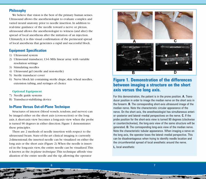
Figure 1. Demonstration of the differencesbetween imaging a structure on the shortaxis versus the long axis. For this demonstration, the patient is in the prone position. A. Trans-ducer position in order to image the median nerve on the short axis inthe forearm. B. The corresponding short-axis ultrasound image of themedian nerve. Note the characteristic circular appearance of thenerve. On the short axis, the anesthesiologist has simultaneous anteri-or–posterior and lateral–medial perspectives on the nerve. C. If theprobe position for the short-axis view is turned 90 degrees (clockwiseor counterclockwise), the long-axis view of the same structure will begenerated. D. The corresponding long-axis view of the median nerve.Note the characteristic tubular appearance. When imaging a nerve onthe long axis, the operator loses the lateral–medial perspective. Thiscan be disadvantageous when trying to identify needle location andthe circumferential spread of local anesthetic around the nerve.
L, local anesthetic
skin surface skin surface
For single-injection nerve blocks, we prefer the in-plane tech-nique.The out-of-plane technique is preferred for continuouscatheter placement.When using the out-of-plane technique, it ishelpful to inject small amounts of saline, local anesthesia, or 5%dextrose solution to help define the location of the needle tip asit advances.The major learning obstacle for the in-plane tech-nique is the ability to keep the needle in the path of the ultra-sound beam.When using the out-of-plane technique, considerthe following:1. Use an ultrasound system with a high-frequency transducer
(up to 13 MHz) for superficial blocks that are ≤3 cm deep.Thisallows the best resolution of the neural structures and sur-rounding tissue. Deeper blocks will require a lower-frequencytransducer that provides better penetration of the ultrasoundbeam into the tissue.
2. The needle is visualized before being advanced when usingthe in-plane technique.The ultrasound beam is very thin,which means that subtle movements can bring the needle inand out of visualization.
3. Subtle pressure or angulation of the transducer (probe) candramatically improve or worsen the image.
4. Practice your needle skills using a turkey breast with an oliveplaced in it. Interventional radiologists use this popularmodel to mimic a cyst in a human breast.
5. Ask the experts at your institution for clinical pearls andinsights.We have gained many tricks of the trade by speakingwith radiologists and ultrasonographers. Specifically, theoperator should be familiar with depth, color flow indica-tors, gain, focus, frequency settings, and image storing.
6. Keep a database of your cases; you will quickly realize theimprovement in efficiency and efficacy of your regionalanesthesia service.
7. Many ultrasound systems provide optional needle-guidedevices for their transducers.These devices secure the needleto the transducer and allow the operator to follow a predeter-mined course to the target of interest.Although on the sur-face these devices may sound attractive, we have found that
to make very precise real-time adjustments (Figures 2A and 2B).When the needle is inserted in the short axis, a cross-sectional
view of the needle will be obtained (Figures 2C and 2D).This isknown as the out-of-plane technique.The out-of-plane tech-nique results in the needle being imaged on cross-section.An18- to 22-gauge needle imaged on cross-section appears as asmall dot, which can be difficult to see in real time. In addition,the needle will cross the ultrasound beam only once.Therefore,when the needle is visualized, it may be well above or below thetarget nerve, depending on the angle of the insertion.
8 9
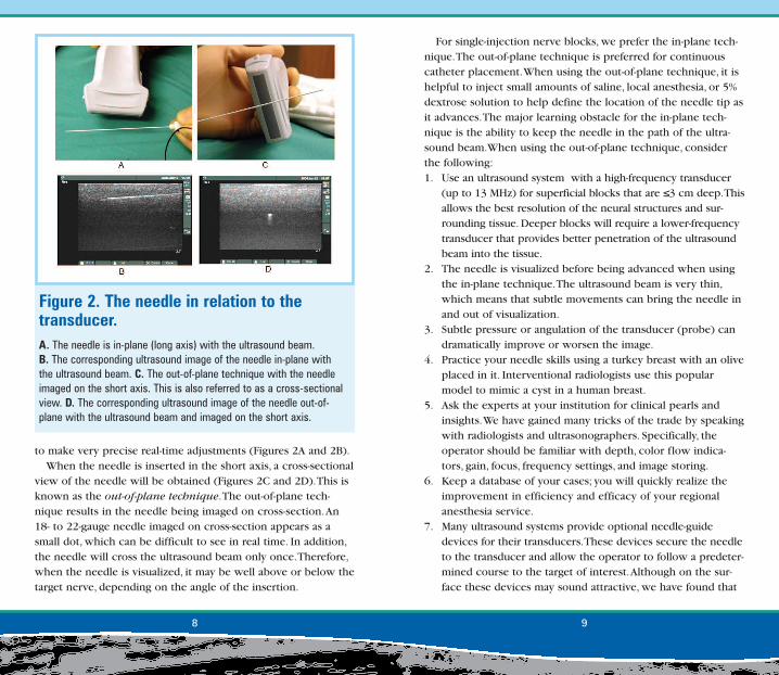
Figure 2. The needle in relation to thetransducer. A. The needle is in-plane (long axis) with the ultrasound beam.B. The corresponding ultrasound image of the needle in-plane withthe ultrasound beam. C. The out-of-plane technique with the needleimaged on the short axis. This is also referred to as a cross-sectionalview. D. The corresponding ultrasound image of the needle out-of-plane with the ultrasound beam and imaged on the short axis.
9. Place the ultrasound machine on the contralateral side of thepatient and have the operator stand on the ipsilateral side ofthe extremity to be blocked.
10. All transducers have an orientation marker that should bepositioned at the upper-left corner of the ultrasound screen,allowing the skin surface to be uppermost.When scanning ina transverse/cross-sectional plane, the marker on the trans-ducer should always point toward the operator’s left side,allowing reproducibility of image orientation.
11. Terminology: hyperechoic, whiter or brighter than surround-ing tissue; hypoechoic, gray or darker in relation to the sur-rounding tissue; anechoic, black.
they often limit the anesthesiologist’s options.That is, oncethe needle is secured into the needle-guide device, onecannot change angles and approaches to the nerve thatwould allow generation of the circumferential spread of localanesthetic around the nerve.
8. The transducer is held in the operator’s nondominant handand the needle in the dominant hand.The ability to use bothhands to drive the needle will give those fortunate individu-als an ergonomic advantage as they will find it easier toestablish an ergonomically stable situation regardless ofblock type and patient position.
10 11
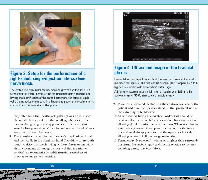
Figure 3. Setup for the performance of aright-sided, single-injection interscalenenerve block.The dotted line represents the interscalene groove and the solid linerepresents the lateral border of the sternocleidomastoid muscle. Fol-lowing the identification of the carotid artery and the internal jugularvein, the transducer is moved in a lateral and posterior direction until itcomes to rest as indicated in this photo.
Figure 4. Ultrasound image of the brachialplexus.Horizontal arrows depict the roots of the brachial plexus at the levelindicated by Figure 5. The roots of the brachial plexus appear as 2 to 4hypoechoic circles with hyperechoic outer rings.
AS, anterior scalene muscle; IJ, internal jugular vein; MS, middlescalene muscle; SCM, sternocleidomastoid muscle
should appear as 2 to 4 hypoechoic circles with hyperechoicouter rings (Figure 4).The nerves should be flanked mediallyand laterally by the anterior and middle scalene muscles.
3. The needle is advanced using the in-plane technique, eitherfrom the posterior aspect (posterior approach, Figure 5) orthe anterior aspect (anterior approach, Figure 6) of the trans-ducer footprint. For shoulder surgery, the needle should beadvanced under direct guidance between the C5 and C6nerve roots.
4. Nerve stimulation may be used to confirm entry into thebrachial plexus sheath.
5. Inject local anesthetic.
Interscalene Nerve BlockPatient Position: Supine with the head rotated toward thenonoperative sideTransducer Location: At level of or below the cricoid cartilageFrequency: HighIn-Plane/Out-of-Plane: In-planeNerve Image: 3 to 4 hypoechoic circles located between theanterior and middle scalene muscle belliesNeedle Size: 50 mmLocal Volume: 20-30 cc
1. Place transducer over the sternocleidomastoid muscle at thelevel of the cricoid cartilage (Figure 3).
2. Image the carotid artery and internal jugular vein in theshort-axis view and then slide the transducer in a lateraland posterior direction.The roots of the brachial plexus
12 13
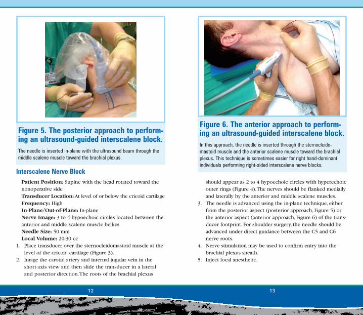
Figure 6. The anterior approach to perform-ing an ultrasound-guided interscalene block.In this approach, the needle is inserted through the sternocleido-mastoid muscle and the anterior scalene muscle toward the brachialplexus. This technique is sometimes easier for right hand-dominantindividuals performing right-sided interscalene nerve blocks.
Figure 5. The posterior approach to perform-ing an ultrasound-guided interscalene block.The needle is inserted in-plane with the ultrasound beam through themiddle scalene muscle toward the brachial plexus.
1514
• Remember that anatomy is variable, especially with the rootsof the brachial plexus.A well-described variant is when 1 ormore of the roots do not exist in the interscalene groove, butpenetrate directly through muscle. In these cases, one willsee the hypoechoic nerve root(s) in either the anterior ormedial scalene muscle.
Supraclavicular Nerve BlockPatient Position: Supine with the head rotated toward thenonoperative sideTransducer Location: Parallel to the clavicle resting in thesupraclavicular fossaFrequency: High In-Plane/Out-of-Plane: In-planeNerve Image: 3 to 6 hypoechoic circles located lateral andsuperior to the subclavian artery
Clinical Pearls• The best view of the brachial plexus is often found more inferi-
or in the neck than expected by the conventional description(ie, more inferior than at the level of the cricoid cartilage).
• If you are having difficulty identifying the neural structures,obtain a supraclavicular image first (see below) and trace theneural structures superiorly up the neck.
• The tip of the lateral end of the sternocleidomastoid muscleshould be slightly posterior–lateral to the superior neuralstructures in the interscalene groove.
• During needle insertion (using the posterior approach), thegreat vessels should not be viewed simultaneously with thebrachial plexus in the interscalene groove (Figure 7). If thegreat vessels are in the image, you may need to move thetransducer in a more posterior lateral direction.
• We use a mechanical device to hold the transducer.Thisdevice allows 1 person to perform the procedure as well aseliminating operator fatigue (Figure 8).
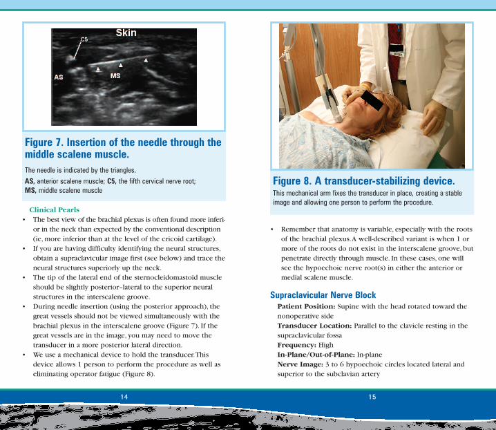
Figure 7. Insertion of the needle through themiddle scalene muscle.The needle is indicated by the triangles.
AS, anterior scalene muscle; C5, the fifth cervical nerve root; MS, middle scalene muscle
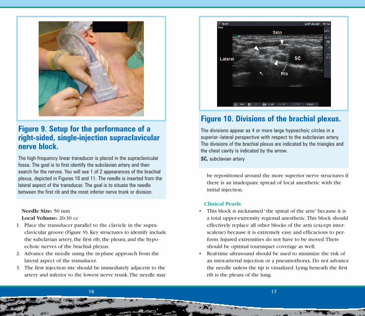
Figure 8. A transducer-stabilizing device.This mechanical arm fixes the transducer in place, creating a stableimage and allowing one person to perform the procedure.
Needle Size: 50 mmLocal Volume: 20-30 cc
1. Place the transducer parallel to the clavicle in the supra-clavicular groove (Figure 9). Key structures to identify includethe subclavian artery, the first rib, the pleura, and the hypo-echoic nerves of the brachial plexus.
2. Advance the needle using the in-plane approach from thelateral aspect of the transducer.
3. The first injection site should be immediately adjacent to theartery and inferior to the lowest nerve trunk.The needle may
16 17
Figure 9. Setup for the performance of aright-sided, single-injection supraclavicularnerve block.The high-frequency linear transducer is placed in the supraclavicularfossa. The goal is to first identify the subclavian artery and thensearch for the nerves. You will see 1 of 2 appearances of the brachialplexus, depicted in Figures 10 and 11. The needle is inserted from thelateral aspect of the transducer. The goal is to situate the needlebetween the first rib and the most inferior nerve trunk or division.
be repositioned around the more superior nerve structures ifthere is an inadequate spread of local anesthetic with theinitial injection.
Clinical Pearls• This block is nicknamed “the spinal of the arm” because it is
a total upper-extremity regional anesthetic.This block shouldeffectively replace all other blocks of the arm (except inter-scalene) because it is extremely easy and efficacious to per-form. Injured extremities do not have to be moved.Thereshould be optimal tourniquet coverage as well.
• Real-time ultrasound should be used to minimize the risk ofan intra-arterial injection or a pneumothorax. Do not advancethe needle unless the tip is visualized. Lying beneath the firstrib is the pleura of the lung.
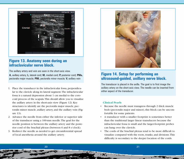
Figure 10. Divisions of the brachial plexus.The divisions appear as 4 or more large hypoechoic circles in asuperior–lateral perspective with respect to the subclavian artery.The divisions of the brachial plexus are indicated by the triangles andthe chest cavity is indicated by the arrow.
SC, subclavian artery

Frequency: 10-5 MHz, depending on the depth of the plexusfrom the surfaceIn-Plane/Out-of-Plane: In-planeNerve Image: 3 hyperechoic exterior nerve structures dis-tributed around the subclavian artery at 3, 6, and 9 o’clockpositionsNeedle Size: 100 mmLocal Volume: 20-30 cc
• For hand surgery, the injection made around the most inferi-or aspect of the brachial plexus is critical to the success ofthis block.This injection should be accomplished first in casethere is any tissue distortion with injection.
• Two distinct appearances of the brachial plexus appear atthe supraclavicular level. One can see a grape-like cluster of5 to 6 hypoechoic circles, which probably represent the divi-sions of the brachial plexus (Figures 10 and 11).When only 3hypoechoic structures are visualized, the operator may bevisualizing the trunks of the brachial plexus.
Infraclavicular Nerve BlockPatient Position: Supine with the head rotated toward thenonoperative sideTransducer Location: Infraclavicular, perpendicular to theclavicle along the lateral segment and in the infraclavicular fossa
18 19
Figure 12. Setup for performing an ultrasound-guided infraclavicular block. The transducer is placed in the infraclavicular fossa. The goal of thetransducer position is to image the axillary artery on the short axisapproximately 1 to 2 cm medial to the corocoid process. The needlecan be inserted from either aspect of the transducer and in line withthe ultrasound beam. The cords of the brachial plexus often appear as3 hyperechoic circles located around the axillary artery (see Figure13). Clinical experience suggests that the primary injection site shouldbe between the axillary artery and the posterior cord. Nerve stimula-tion is helpful in this block because the cords, being much deeper thanthe more proximal brachial plexus, are harder to visualize.
Figure 11. Trunks of the brachial plexus.The trunks should appear as 3 hypoechoic circles stacked on oneanother in a linear fashion.
I, inferior trunk; M, middle trunk; S, superior trunk; SC, subclavian artery
Clinical Pearls• Because the needle must transgress through 2 thick muscle
beds (pectoralis major and minor), this block can be uncom-fortable for some patients.
• A transducer with a smaller footprint is sometimes betterthan the traditional larger linear transducers because theinfraclavicular fossa is small and the larger-footprint probescan hang over the clavicle.
• The cords of the brachial plexus tend to be more difficult tovisualize compared with the roots, trunks, and divisions.Thisdifficulty is secondary to the deeper location of the cords.
1. Place the transducer in the infraclavicular fossa, perpendicu-lar to the clavicle along its lateral segment.The infraclavicularfossa is a natural depression about 1 cm medial to the coro-coid process of the scapula.This should allow you to visualizethe axillary artery in the short-axis view (Figure 12). Keystructures to identify are the pectoralis major muscle, pec-toralis minor muscle, axillary artery, and the axillary vein (Fig-ure 13).
2. Advance the needle from either the inferior or superior sideof the transducer using a 100-mm needle.The goal for theneedle position is between the axillary artery and the poste-rior cord of the brachial plexus (between 6 and 8 o’clock).
3. Redirect the needle as needed to get circumferential spreadof local anesthesia around the axillary artery.
20 21
Figure 14. Setup for performing an ultrasound-guided, axillary nerve block.The transducer is placed in the axilla. The goal is to first image theaxillary artery on the short-axis view. The needle can be inserted fromeither aspect of the transducer.
Figure 13. Anatomy seen during an infraclavicular nerve block.The axillary artery and vein are seen in the short-axis view.
A, axillary artery; L, lateral cord; M, medial cord; P, posterior cord; PMa,pectoralis major muscle; PMi, pectoralis minor muscle; V, axillary vein
patients.The median nerve tends to appear consistently atthe 12 o’clock position with the ulnar nerve between the 2and 5 o’clock positions.The radial nerve varies, but tends toappear between 4 and 9 o’clock (Figure 15).
3. Advance the needle from either side of the transducer, usingthe in-plane approach. First, we recommend targeting thenerves that are anticipated to be involved in the surgery. Fol-lowing an injection, there can be significant distortion of theanatomy.
Deeper structures cannot be imaged with the highest frequency (highest resolution) transducers.
• We reserve infraclavicular blocks for situations in whichthere is a relative contraindication to a supraclavicular block(eg, subclavian artery pathology, localized infection, andsevere chronic obstructive pulmonary disease [COPD]).Because one may anesthetize the phrenic nerve with a supra-clavicular block, this block should be performed judiciouslyin a patient who has severe COPD.
Axillary Plexus BlockPatient Position: Supine with the head rotated toward thenonoperative side.The patient’s arm is abducted and externallyrotated.Transducer Location: In the axilla at the crease formed bythe pectoralis major and biceps muscles; perpendicular tothe axillary arteryFrequency: High In-Plane/Out-of-Plane: In-planeNerve Image: The nerves will be located in a variable fashionaround the axillary artery.The nerves appear as complex,hyperechoic, and circular or oval structures with the internalfascicles appearing as multiple hypoechoic smaller circles.Needle Size: 50 mmLocal Volume: 20-30 ccNote: The musculocutaneous nerve will be addressed in thenext section.
1. Place the transducer in the axilla perpendicular to the courseof the axillary artery and roughly at the level of the creaseformed by the pectoralis major and biceps muscles (Figure 14).
2. Obtain an image of the axillary artery and vein(s) in theshort-axis view.You may use color Doppler to distinguish theartery from the vein.The artery should be noncompressibleand pulsating, and the vein should be compressible and havecontinuous steady flow.The median, ulnar, and radial nervesmost likely will surround the artery in a triangular pattern;however, their exact location may vary significantly among
22 23
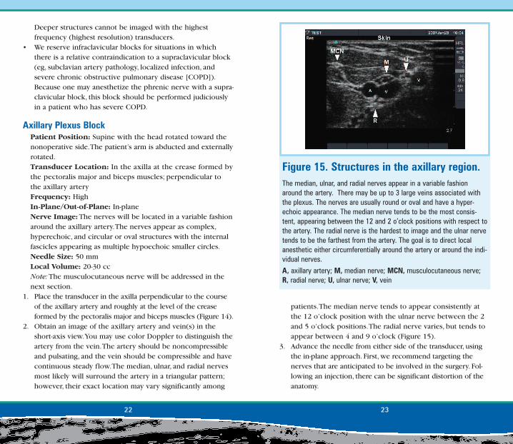
Figure 15. Structures in the axillary region.The median, ulnar, and radial nerves appear in a variable fashionaround the artery. There may be up to 3 large veins associated withthe plexus. The nerves are usually round or oval and have a hyper-echoic appearance. The median nerve tends to be the most consis-tent, appearing between the 12 and 2 o’clock positions with respect tothe artery. The radial nerve is the hardest to image and the ulnar nervetends to be the farthest from the artery. The goal is to direct localanesthetic either circumferentially around the artery or around the indi-vidual nerves.
A, axillary artery; M, median nerve; MCN, musculocutaneous nerve;R, radial nerve; U, ulnar nerve; V, vein
• Arguably less artistic, but easier to do, is to simply use ultra-sound guidance to generate local anesthetic spread in a cir-cumferential pattern around the axillary artery (the doughnutsign).We reserve this technique for situations in which it is astruggle to image the individual nerves.
• Because local anesthetics are hypoechoic, the spread of theinjection is very easy to visualize. If the local anesthetic isinjected into a blood vessel, the drug will be carried away andthus not visualized.Therefore, if the local anesthetic is notvisualized spreading around the artery, the practitioner shouldassume an intravascular injection and reposition the needle.
4. Inject local anesthetic. Depending on the image quality, thegoal will be to visualize the local anesthetic surrounding thetargeted nerves.You may reposition the needle as needed toobtain appropriate coverage.
Clinical Pearls• Nerve stimulation may be helpful in identifying nerves several
centimeters away from the artery and in a variable orienta-tion.The nerve stimulator is a great physiologic test of youranatomic assumptions.
• The ulnar nerve may be located several centimeters from theartery. In addition, this nerve may be situated next to one ofthe axillary veins instead of the axillary artery.
• There may be multiple veins associated with the axillarybrachial plexus.
24 25
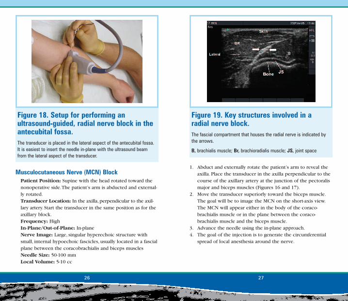
Figure 17. The MCN in the axilla.The short-axis image of the MCN in the axilla at the level described inFigure 16. The nerve appears as a hyperechoic, circular structure lyingbetween the 2 muscle beds. The nerve is indicated by the triangles.
BM, biceps muscle; CB, corocobrachialis muscle; MCN, musculocuta-neous nerve
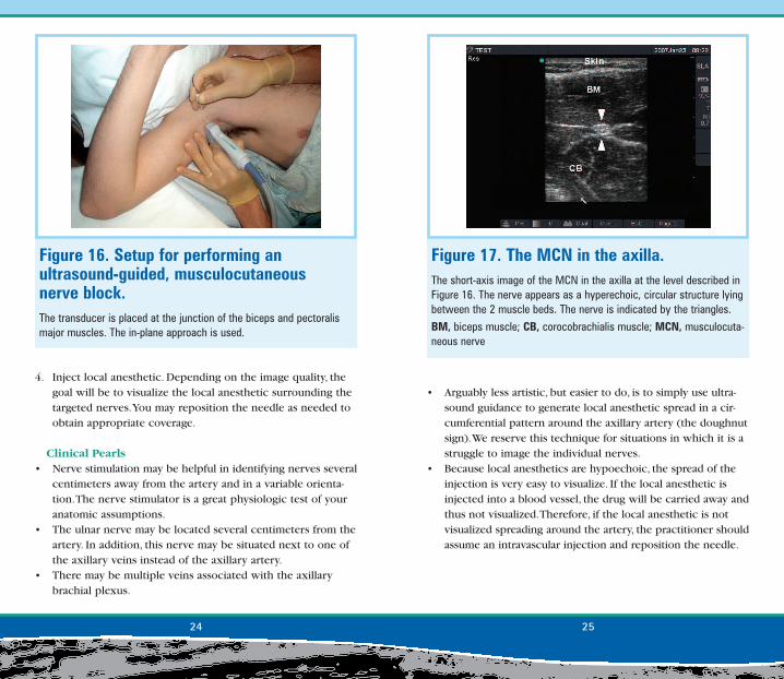
Figure 16. Setup for performing an ultrasound-guided, musculocutaneous nerve block.The transducer is placed at the junction of the biceps and pectoralismajor muscles. The in-plane approach is used.
1. Abduct and externally rotate the patient’s arm to reveal theaxilla. Place the transducer in the axilla perpendicular to thecourse of the axillary artery at the junction of the pectoralismajor and biceps muscles (Figures 16 and 17).
2. Move the transducer superiorly toward the biceps muscle.The goal will be to image the MCN on the short-axis view.The MCN will appear either in the body of the coraco-brachialis muscle or in the plane between the coraco-brachialis muscle and the biceps muscle.
3. Advance the needle using the in-plane approach.4. The goal of the injection is to generate the circumferential
spread of local anesthesia around the nerve.
Musculocutaneous Nerve (MCN) BlockPatient Position: Supine with the head rotated toward thenonoperative side.The patient’s arm is abducted and external-ly rotated.Transducer Location: In the axilla, perpendicular to the axil-lary artery. Start the transducer in the same position as for theaxillary block.Frequency: High In-Plane/Out-of-Plane: In-planeNerve Image: Large, singular hyperechoic structure withsmall, internal hypoechoic fascicles, usually located in a fascialplane between the coracobrachialis and biceps musclesNeedle Size: 50-100 mmLocal Volume: 5-10 cc
26 27
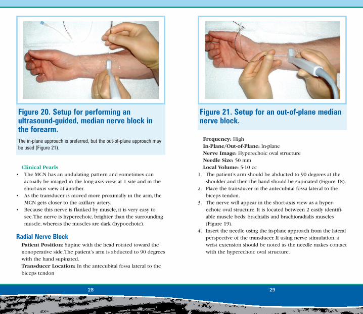
Figure 18. Setup for performing an ultrasound-guided, radial nerve block in theantecubital fossa.The transducer is placed in the lateral aspect of the antecubital fossa.It is easiest to insert the needle in-plane with the ultrasound beamfrom the lateral aspect of the transducer.
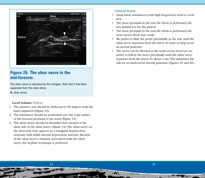
Figure 19. Key structures involved in a radial nerve block. The fascial compartment that houses the radial nerve is indicated bythe arrows.
B, brachialis muscle; Br, brachioradialis muscle; JS, joint space
Frequency: HighIn-Plane/Out-of-Plane: In-planeNerve Image: Hyperechoic oval structureNeedle Size: 50 mmLocal Volume: 5-10 cc
1. The patient’s arm should be abducted to 90 degrees at theshoulder and then the hand should be supinated (Figure 18).
2. Place the transducer in the antecubital fossa lateral to thebiceps tendon.
3. The nerve will appear in the short-axis view as a hyper-echoic oval structure. It is located between 2 easily identifi-able muscle beds: brachialis and brachioradialis muscles(Figure 19).
4. Insert the needle using the in-plane approach from the lateralperspective of the transducer. If using nerve stimulation, awrist extension should be noted as the needle makes contactwith the hyperechoic oval structure.
Clinical Pearls• The MCN has an undulating pattern and sometimes can
actually be imaged in the long-axis view at 1 site and in theshort-axis view at another.
• As the transducer is moved more proximally in the arm, theMCN gets closer to the axillary artery.
• Because this nerve is flanked by muscle, it is very easy tosee.The nerve is hyperechoic, brighter than the surroundingmuscle, whereas the muscles are dark (hypoechoic).
Radial Nerve BlockPatient Position: Supine with the head rotated toward thenonoperative side.The patient’s arm is abducted to 90 degreeswith the hand supinated.Transducer Location: In the antecubital fossa lateral to thebiceps tendon
28 29
Figure 20. Setup for performing an ultrasound-guided, median nerve block inthe forearm.The in-plane approach is preferred, but the out-of-plane approach maybe used (Figure 21).
Figure 21. Setup for an out-of-plane mediannerve block.

Transducer Location: Volar surface of the distal forearmFrequency: HighIn-Plane/Out-of-Plane: In-plane or out-of-planeNerve Image: Single hyperechoic structure with smallhypoechoic fasciclesNeedle Size: 50 mmLocal Volume: 5-10 cc
1. The patient’s arm should be abducted to 90 degrees with thehand supinated (Figure 20).
2. The transducer should be positioned over the volar surfaceof the forearm proximal to the wrist.
3. The median nerve can be located between the palmarislongus tendon and the flexor carpi radialis tendon andtraced proximal to the desired level for placement of theblock.The goal is to see the nerve on the short-axis view at a
Clinical Pearls• The radial nerve is usually accompanied by a small artery at
the level of the antecubital fossa.We recommend screeningthe nerve region with color Doppler before inserting theneedle.
• Do not confuse the median nerve in the antecubital fossawith the radial nerve.The median nerve is located in themedial aspect of the arm next to the brachial artery.
Median Nerve Block: Single InjectionPatient Position: Supine with the head rotated toward thenonoperative side.The patient’s arm is abducted to 90 degreeswith the hand supinated.
30 31
Figure 22. The median nerve imaged on the short-axis view in the mid-forearm. The nerve appears as a hyperechoic circle or triangle. The internalhypoechoic fascicles can easily be seen. The nerve is indicated by thearrows and the tendons are indicated by the triangles. The radial sideof the screen is indicated.
Figure 23. Setup for performing an ultrasound-guided ulnar nerve block in thedistal forearm. The ulnar nerve at the level indicated in this figure lies immediately tothe ulnar side of the ulnar artery (Figure 24).

• Tendons can be easily confused with the median nerve (Figure22).The tendons appear flatter than the nerve and become lessdistinct as the transducer is moved proximally in the arm.
Ulnar Nerve BlockPatient Position: Supine with the head rotated toward thenonoperative side.The patient’s arm is abducted to 90 degreeswith the hand supinated.Probe Location: Volar surface of the distal forearmFrequency: HighIn-Plane/Out-of-Plane: In-plane or out-of-planeNerve Image: Hyperechoic structure with small internalhypoechoic fasciclesNeedle Size: 50 mm
level of the arm that avoids any collateral targets such asblood vessels or tendons.The nerve appears as a large hyper-echoic circular or oval structure.The internal hypoechoicfascicles of the nerve can also be seen.
4. The approach can involve either the in-plane or out-of-planetechnique, whichever is ergonomically more comfortable(Figure 21).
Clinical Pearls• Small linear transducers with high frequencies tend to work
best.• The more proximal in the arm the block is performed, the
less painful it is for the patient.• The more proximal in the arm the block is performed, the
more motor block may result.
32 33
Figure 24. The ulnar nerve in the distal forearm.The ulnar nerve is indicated by the triangles. The nerve is hyperechoicand triangular.
A, ulnar artery
Figure 25. Setup for performing an ultrasound-guided ulnar nerve block in themid-forearm.The ulnar nerve at this level has been separated from the ulnar artery.In the mid-forearm, the in-plane approach is preferred, inserting theneedle from the radial side of the transducer.
Clinical Pearls• Small linear transducers with high frequencies tend to work
best.• The more proximal in the arm the block is performed, the
less painful it is for the patient.• The more proximal in the arm the block is performed, the
more motor block may result.• We prefer to slide the probe proximally in the arm until the
ulnar nerve separates from the artery in order to help avoidan arterial puncture.
• The nerve can be blocked at the wrist crease; however, weprefer to follow the nerve proximally until the ulnar nerveseparates from the artery by about 1 cm.This minimizes therisk for an inadvertent arterial puncture (Figures 25 and 26).
Local Volume: 5-10 cc1. The patient’s arm should be abducted to 90 degrees with the
hand supinated (Figure 23).2. The transducer should be positioned over the volar surface
of the forearm proximal to the wrist (Figure 23).3. The ulnar artery should be identified first, located at the
ulnar side of the ulnar artery (Figure 24).The ulnar nerve onthe short-axis view appears as a triangular, hyperechoicstructure with small, internal hypoechoic fascicles. Becauseof the ulnar nerve’s intimate association with the ulnarartery, the in-plane technique is preferred.
34 35
Figure 26. The ulnar nerve in the mid-forearm. The ulnar nerve is indicated by the triangles. Note that it has beenseparated from the ulnar artery.
A, ulnar artery