Embed Size (px)
Citation preview
LEFM 280C User Manual IB0510 Rev. 06
Manual No. IB0510 Rev. 06
CALDON® ULTRASONICS
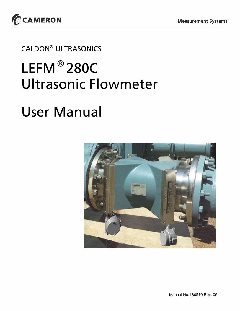
LEFM® 280CUltrasonic Flowmeter
User Manual

IB0510 Rev. 06 LEFM 280C User Manual
Caldon is a trademark of Cameron International Corporation (“Cameron”).LEFM is a registered trademark of Cameron.ModBus is a registered trademark of ModBus Organization, Inc.
Copyright © 2008 Cameron International Corporation (“Cameron”). All information contained inthis publication is confidential and proprietary property of Cameron. Any reproduction or use ofthese instructions, drawings, or photographs without the express written permission of an officer ofCameron is forbidden.
All Rights Reserved.Printed in the United States of America
Manual No. IB0510 Rev. 06November 2008
LEFM 280C User Manual IB0510 Rev. 06
November 2008 Page i Table of Contents
TABLE OF CONTENTS
INTRODUCTION III
1.0 EQUIPMENT SPECIFICATION 1
1.1 LEFM 280C EQUIPMENT .....................................................................................................................1
1.1.1 LEFM TRANSMITTER..........................................................................................................................1
1.1.2 LEFM 280C METER BODY SECTION.................................................................................................3
1.2 LEFM 280C MODEL NUMBER............................................................................................................4
1.2.1 LEFM 280C MODEL NUMBER............................................................................................................4
1.2.2 LEFM 280C LT MODEL NUMBER (CRYOGENIC TEMPERATURE RANGE) ..............................4
1.2.3 LEFM 280C PART CODE ......................................................................................................................5
1.3 LEFM 280C SPECIFICATIONS ............................................................................................................7
1.3.1 LEFM 280C TRANSMITTER ................................................................................................................7
1.3.2 APPROVALS – TRANSMITTER, LEFM 280C-T-….-EX ...................................................................8
1.3.3 APPROVALS – METER BODY, LEFM 280C-M AND LEFM 280C-LT-M .......................................8
1.3.4 ENVIRONMENT (TRANSMITTER AND METER BODY) ..............................................................10
1.3.5 LEFM 280C AND 280C-LT WITH J-BOXES - METER BODY SPECIFICATIONS........................11
1.3.6 LEFM 280C LT METER BODY SPECIFICATIONS (WITHOUT J-BOXES)...................................15
2.0 INSTALLATION 17
2.1 TRANSMITTER ...................................................................................................................................17
2.1.1 TRANSMITTER MOUNTING.............................................................................................................17
2.1.2 FIELD TERMINATIONS .....................................................................................................................18
2.1.3 TERMINATIONS - DIGITAL SIGNALS ............................................................................................18
2.1.4 GROUNDING/EARTHING (METER BODY AND TRANSMITTER)..............................................18
2.2 FLOW METER BODY .........................................................................................................................19
2.2.1 METER BODY TERMINATIONS.......................................................................................................19
2.2.2 UPSTREAM AND DOWNSTREAM PIPING .....................................................................................19
2.2.3 FLOW DIRECTION..............................................................................................................................19
2.2.4 GAS (AIR) IN THE FLOW STREAM..................................................................................................20
2.3 METER INSTALLATION CHECK-OUT............................................................................................31
3.0 OPERATION 33
3.1 MEASURING VELOCITIES................................................................................................................33
3.2 MEASURING FLOWRATE.................................................................................................................34
3.3 LEFM 280C TRANSMITTER ..............................................................................................................35
3.4 LEFM 280C FAULT DETECTION......................................................................................................35
IB0510 Rev. 06 LEFM 280C User Manual
Table of Contents Page ii November 2008
3.5 GROSS TO NET FLOWRATE CONVERSION ..................................................................................36
3.6 REMOTE DATA COMMUNICATIONS.............................................................................................37
4.0 MAINTENANCE 39
4.1 INTRODUCTION .................................................................................................................................39
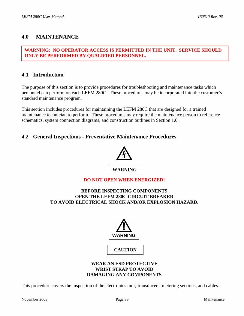
4.2 GENERAL INSPECTIONS - PREVENTATIVE MAINTENANCE PROCEDURES........................39
4.3 POWER SUPPLY VOLTAGE TROUBLESHOOTING AND MAINTENANCE ..............................41
4.4 METERING SECTION AND TRANSDUCER CABLES ...................................................................44
4.5 TRANSDUCER INSTALLATION PROCEDURE ..............................................................................45
4.6 ANALOG INPUT ALIGNMENT AND VERIFICATION PROCEDURE..........................................51
4.7 ANALOG OUTPUT VERIFICATION.................................................................................................52
4.7.1 ANALOG SCALING ............................................................................................................................52
4.7.2 PULSE VERIFICATION TESTS..........................................................................................................52
5.0 TROUBLESHOOTING AND DIAGNOSTICS FOR THE ULTRASONICS 55
5.1 DIAGNOSTICS.....................................................................................................................................55
5.2 PATH TROUBLESHOOTING .............................................................................................................57
5.2.1 PATH REJECT STATUS......................................................................................................................57
5.3 REPROGRAMMING THE TRANSMITTER ......................................................................................59
5.3.1 MODBUS ID AND BAUD RATE........................................................................................................60
6.0 RECOMMENDED SPARE PARTS 63
6.1 DOMESTIC (US AND CANADA).......................................................................................................63
6.2 INTERNATIONAL ...............................................................................................................................63
7.0 APPENDIX A 65
7.1 ATEX CERTIFICATIONS (DOCUMENT IB0613) ............................................................................65
LEFM 280C User Manual IB0510 Rev. 06
November 2008 Page iii Introduction
INTRODUCTION
The Caldon® LEFM 280C Ultrasonic Flow Meter is a highly sophisticated flow measurement system. Itemploys the ultrasonic transit time method to measure fluid velocity and volumetric flowrate. It containsadvanced signal and data processing circuitry to achieve high accuracy and repeatability. It also containsan automatic self-checking system to continuously verify that it is performing properly and to initiatewarnings and alarms when unsatisfactory conditions are detected. For ease of troubleshooting, it providesvia ModBus easy to interpret diagnostic information.
It is recommended that before performing system verification and repair procedures, personnel receivegeneral training from Cameron. Contact Cameron's Measurement Systems division for information ontraining programs.
A complete range of support services are offered. For additional information or assistance on theapplication, operation or servicing of the LEFM 280C, write or call, or visit www.c-a-m.com/flo.
CAUTION
NO OPERATOR ACCESS IS PERMITTED IN THE UNIT. SERVICE SHOULDONLY BE PERFORMED BY QUALIFIED PERSONNEL.
IF THE EQUIPMENT IS USED IN A MANNER NOT SPECIFIED BY THEMANUFACTURER, THE PROTECTION PROVIDED BY THE EQUIPMENT MAYBE IMPAIRED.

IB0510 Rev. 06 LEFM 280C User Manual
Introduction Page iv November 2008
LEFM 280C User Manual IB0510 Rev. 06
November 2008 Page 1 Equipment Specification
1.0 EQUIPMENT SPECIFICATION
1.1 LEFM 280C Equipment
LEFM 280C Flow Measurement Systems consist of two types of equipment.
1. LEFM 280C Transmitters2. LEFM 280C Meter body or Metering Section, including transducers, cables for transducers,
temperature transmitters, and pressure transmitters (optional)
1.1.1 LEFM Transmitter
Each LEFM 280C transmitter is a wall mount unit with the following special features:
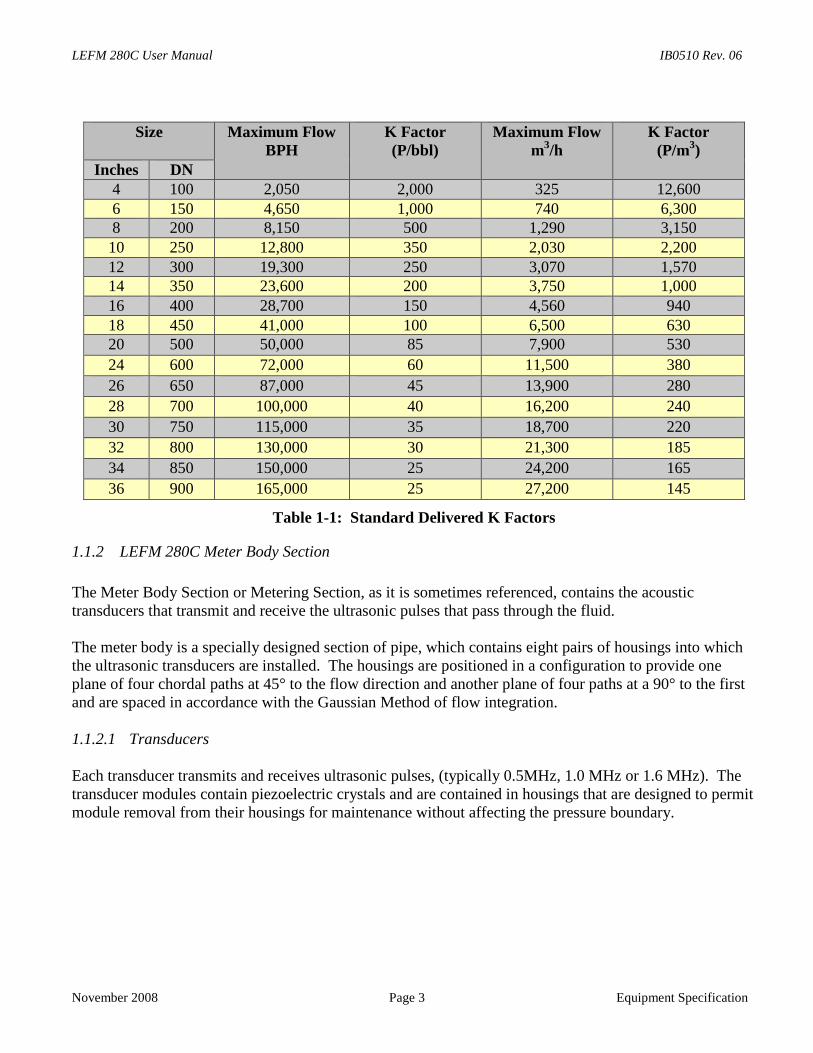
• Standard Outputs:Pulse (0-5 V standard); the meter K factor is programmable. The standard factory delivered
K factors are listed in Table 1-1 below.
• Optional Analog Inputs of:Product temperature (RTD, 4-20, or 0-20mA)Product pressure (4-20, or 0-20 mA)Product density (Frequency, 4-20 or 0-20 mA)
• Optional Analog Outputs of:Flow (4-20, or 0-20 mA)Sound Velocity (4-20, or 0-20 mA)Product Specific Gravity (4-20, or 0-20 mA)Temperature (4-20, or 0-20 mA)
Any analog output may be mapped to any ModBus input register.
The LEFM 280C transmitter contains signal processing and digital computing circuitry, and power supplyequipment.
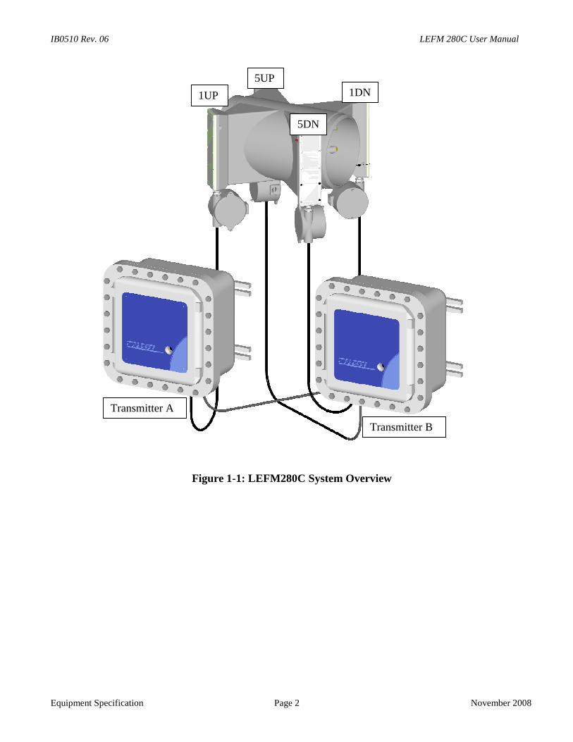
There are two LEFM280C transmitters delivered with each LEFM280C meter. The transmitters arereferred to as Transmitter A and Transmitter B. Transmitter A is connected to acoustic paths numbered 1-4. Transmitter B is connected to acoustic paths numbered 5-8. The two transmitters are completelyindependent of each other and are in effect two LEFM240C meters (See Figure 1-1).
IB0510 Rev. 06 LEFM 280C User Manual
Equipment Specification Page 2 November 2008
Figure 1-1: LEFM280C System Overview
Transmitter A
Transmitter B
1UP
5UP
5DN
1DN
LEFM 280C User Manual IB0510 Rev. 06
November 2008 Page 3 Equipment Specification
Size Maximum FlowBPH
K Factor(P/bbl)
Maximum Flowm3/h
K Factor(P/m3)
Inches DN4 100 2,050 2,000 325 12,6006 150 4,650 1,000 740 6,3008 200 8,150 500 1,290 3,15010 250 12,800 350 2,030 2,20012 300 19,300 250 3,070 1,57014 350 23,600 200 3,750 1,00016 400 28,700 150 4,560 94018 450 41,000 100 6,500 63020 500 50,000 85 7,900 530
24 600 72,000 60 11,500 380
26 650 87,000 45 13,900 280
28 700 100,000 40 16,200 240
30 750 115,000 35 18,700 220
32 800 130,000 30 21,300 185
34 850 150,000 25 24,200 165
36 900 165,000 25 27,200 145
Table 1-1: Standard Delivered K Factors
1.1.2 LEFM 280C Meter Body Section
The Meter Body Section or Metering Section, as it is sometimes referenced, contains the acoustictransducers that transmit and receive the ultrasonic pulses that pass through the fluid.
The meter body is a specially designed section of pipe, which contains eight pairs of housings into whichthe ultrasonic transducers are installed. The housings are positioned in a configuration to provide oneplane of four chordal paths at 45° to the flow direction and another plane of four paths at a 90° to the firstand are spaced in accordance with the Gaussian Method of flow integration.
1.1.2.1 Transducers
Each transducer transmits and receives ultrasonic pulses, (typically 0.5MHz, 1.0 MHz or 1.6 MHz). Thetransducer modules contain piezoelectric crystals and are contained in housings that are designed to permitmodule removal from their housings for maintenance without affecting the pressure boundary.
IB0510 Rev. 06 LEFM 280C User Manual
Equipment Specification Page 4 November 2008
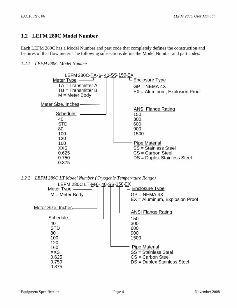
1.2 LEFM 280C Model Number
Each LEFM 280C has a Model Number and part code that completely defines the construction andfeatures of that flow meter. The following subsections define the Model Number and part codes.
1.2.1 LEFM 280C Model Number
1.2.2 LEFM 280C LT Model Number (Cryogenic Temperature Range)
GP = NEMA 4X
M = Meter BodyEX = Aluminum, Explosion Proof
ANSI Flange RatingSchedule: 15040 300STD 60080 900100 1500120160 Pipe MaterialXXS SS = Stainless Steel0.625 CS = Carbon Steel0.750 DS = Duplex Stainless Steel0.875
TA = Transmitter ATB = Transmitter B
Enclosure Type
Meter Size, Inches
Meter Type
M = Meter Body GP = NEMA 4XEX = Aluminum, Explosion Proof
15040 300STD 60080 900100 1500120160 Pipe MaterialXXS SS = Stainless Steel0.625 CS = Carbon Steel0.750 DS = Duplex Stainless Steel0.875
Enclosure Type
ANSI Flange RatingSchedule:
Meter Size, Inches
Meter Type
280C-TA-LEFM 6- 40-SS-150-EX
280C LT-M-LEFM 6- 40-SS-150-EX
LEFM 280C User Manual IB0510 Rev. 06
November 2008 Page 5 Equipment Specification
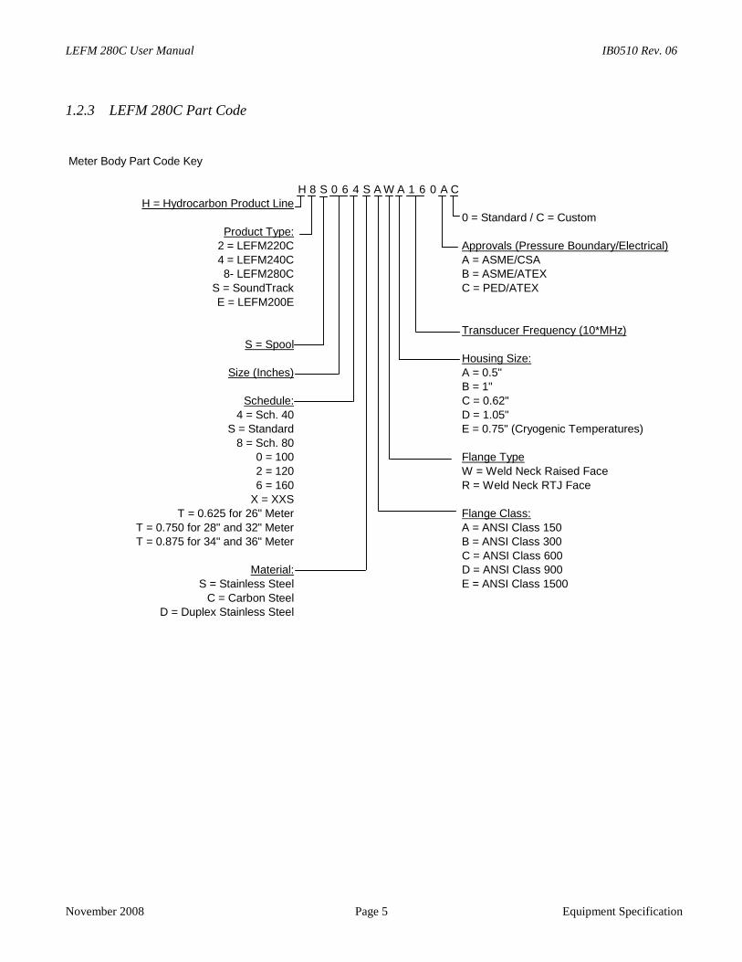
1.2.3 LEFM 280C Part Code
Meter Body Part Code Key
H 8 S 0 6 4 S A W A 1 6 0 A CH = Hydrocarbon Product Line
0 = Standard / C = CustomProduct Type:
2 = LEFM220C Approvals (Pressure Boundary/Electrical)4 = LEFM240C A = ASME/CSA8- LEFM280C B = ASME/ATEX
S = SoundTrack C = PED/ATEXE = LEFM200E
Transducer Frequency (10*MHz)S = Spool
Housing Size:Size (Inches) A = 0.5"
B = 1"Schedule: C = 0.62"
4 = Sch. 40 D = 1.05"S = Standard E = 0.75" (Cryogenic Temperatures)
8 = Sch. 800 = 100 Flange Type2 = 120 W = Weld Neck Raised Face6 = 160 R = Weld Neck RTJ Face
X = XXST = 0.625 for 26" Meter Flange Class:
T = 0.750 for 28" and 32" Meter A = ANSI Class 150T = 0.875 for 34" and 36" Meter B = ANSI Class 300
C = ANSI Class 600Material: D = ANSI Class 900
S = Stainless Steel E = ANSI Class 1500C = Carbon Steel
D = Duplex Stainless Steel
IB0510 Rev. 06 LEFM 280C User Manual
Equipment Specification Page 6 November 2008
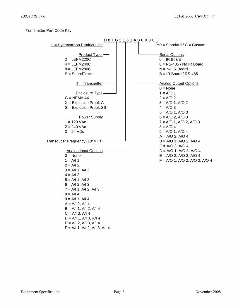
Transmitter Part Code Key
H 8 T G 2 1 6 1 A B 0 0 0 0 CH = Hydrocarbon Product Line 0 = Standard / C = Custom
Product Type: Serial Options2 = LEFM220C 0 = IR Board4 = LEFM240C 8 = RS-485 / No IR Board8 = LEFM280C N = No IR BoardS = SoundTrack B = IR Board / RS-485
T = Transmitter Analog Output Options0 = None
Enclosure Type 1 = A/O 1G = NEMA 4X 2 = A/O 2X = Explosion Proof, Al 3 = A/O 1, A/O 2
S = Explosion Proof, SS 4 = A/O 35 = A/O 1, A/O 3
Power Supply 6 = A/O 2, A/O 31 = 120 VAc 7 = A/O 1, A/O 2, A/O 32 = 240 VAc 8 = A/O 43 = 24 VDc 9 = A/O 1, A/O 4
A = A/O 2, A/O 4Transducer Frequency (10*MHz) B = A/O 1, A/O 2, A/O 4
C = A/O 3, A/O 4Analog Input Options D = A/O 1, A/O 3, A/O 4
0 = None E = A/O 2, A/O 3, A/O 4
1 = A/I 1 F = A/O 1, A/O 2, A/O 3, A/O 42 = A/I 23 = A/I 1, A/I 24 = A/I 35 = A/I 1, A/I 36 = A/I 2, A/I 37 = A/I 1, A/I 2, A/I 38 = A/I 49 = A/I 1, A/I 4A = A/I 2, A/I 4
B = A/I 1, A/I 2, A/I 4C = A/I 3, A/I 4D = A/I 1, A/I 3, A/I 4E = A/I 2, A/I 3, A/I 4F = A/I 1, A/I 2, A/I 3, A/I 4
LEFM 280C User Manual IB0510 Rev. 06
November 2008 Page 7 Equipment Specification
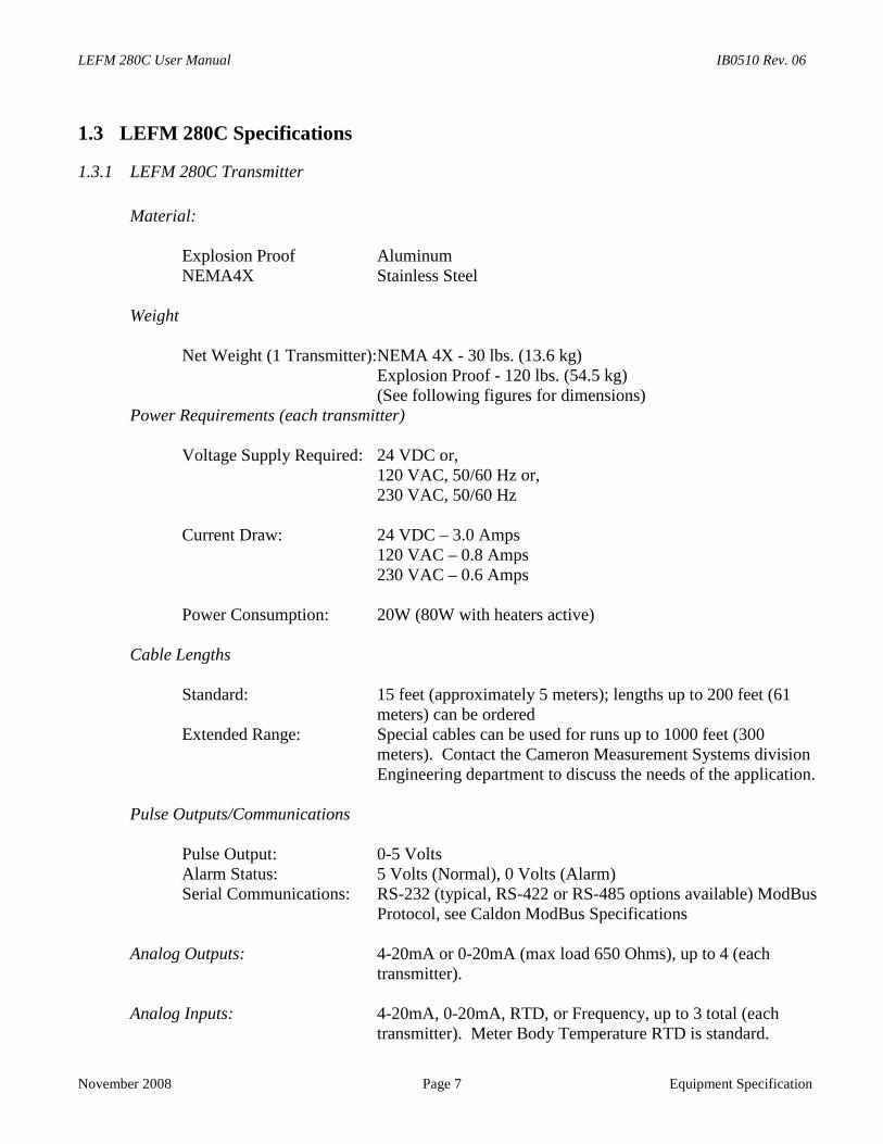
1.3 LEFM 280C Specifications
1.3.1 LEFM 280C Transmitter
Material:
Explosion Proof AluminumNEMA4X Stainless Steel
Weight
Net Weight (1 Transmitter):NEMA 4X - 30 lbs. (13.6 kg)Explosion Proof - 120 lbs. (54.5 kg)(See following figures for dimensions)
Power Requirements (each transmitter)
Voltage Supply Required: 24 VDC or,120 VAC, 50/60 Hz or,230 VAC, 50/60 Hz
Current Draw: 24 VDC – 3.0 Amps120 VAC – 0.8 Amps230 VAC – 0.6 Amps
Power Consumption: 20W (80W with heaters active)
Cable Lengths
Standard: 15 feet (approximately 5 meters); lengths up to 200 feet (61meters) can be ordered
Extended Range: Special cables can be used for runs up to 1000 feet (300meters). Contact the Cameron Measurement Systems divisionEngineering department to discuss the needs of the application.
Pulse Outputs/Communications
Pulse Output: 0-5 VoltsAlarm Status: 5 Volts (Normal), 0 Volts (Alarm)Serial Communications: RS-232 (typical, RS-422 or RS-485 options available) ModBus
Protocol, see Caldon ModBus Specifications
Analog Outputs: 4-20mA or 0-20mA (max load 650 Ohms), up to 4 (eachtransmitter).
Analog Inputs: 4-20mA, 0-20mA, RTD, or Frequency, up to 3 total (eachtransmitter). Meter Body Temperature RTD is standard.
IB0510 Rev. 06 LEFM 280C User Manual
Equipment Specification Page 8 November 2008
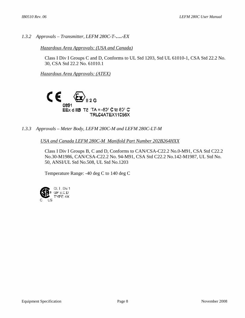
1.3.2 Approvals – Transmitter, LEFM 280C-T-….-EX
Hazardous Area Approvals: (USA and Canada)
Class I Div I Groups C and D, Conforms to UL Std 1203, Std UL 61010-1, CSA Std 22.2 No.30, CSA Std 22.2 No. 61010.1
Hazardous Area Approvals: (ATEX)
1.3.3 Approvals – Meter Body, LEFM 280C-M and LEFM 280C-LT-M
USA and Canada LEFM 280C-M Manifold Part Number 202B264HXX
Class I Div I Groups B, C and D, Conforms to CAN/CSA-C22.2 No.0-M91, CSA Std C22.2No.30-M1986, CAN/CSA-C22.2 No. 94-M91, CSA Std C22.2 No.142-M1987, UL Std No.50, ANSI/UL Std No.508, UL Std No.1203
Temperature Range: -40 deg C to 140 deg C
LEFM 280C User Manual IB0510 Rev. 06
November 2008 Page 9 Equipment Specification
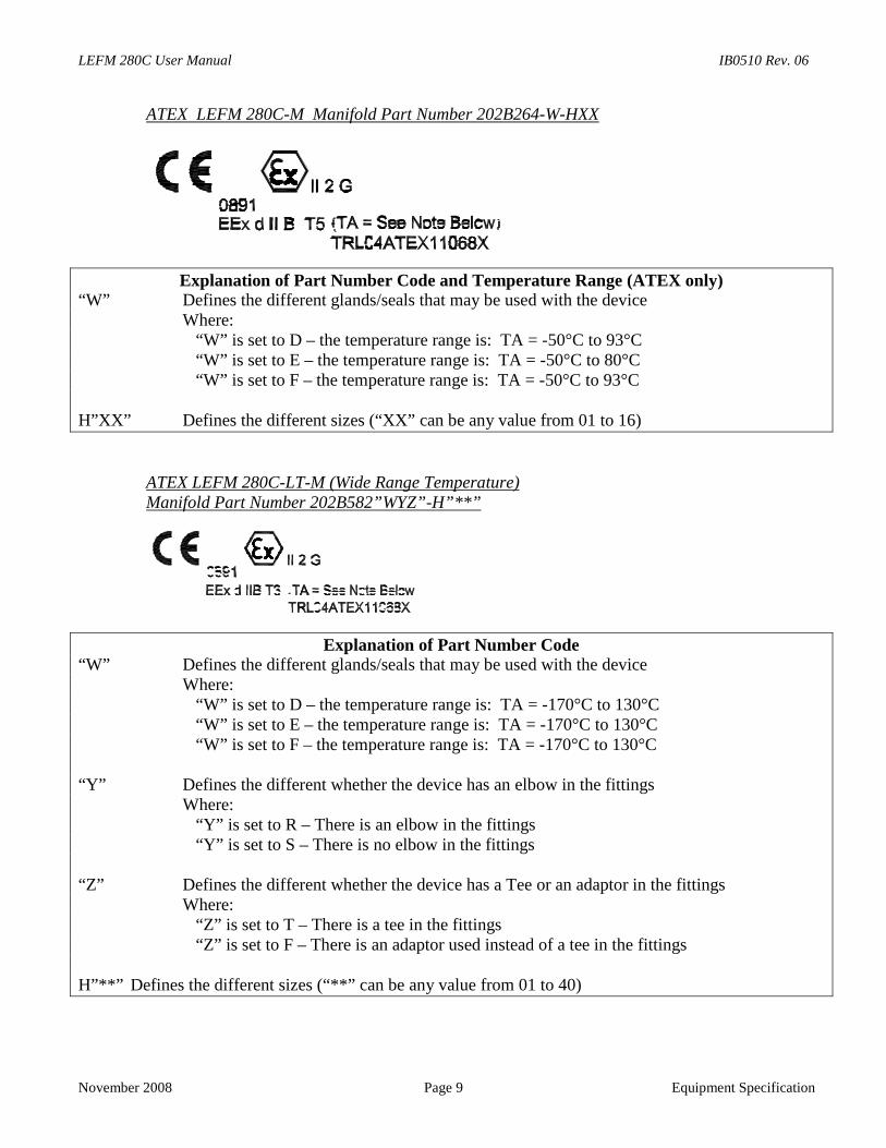
ATEX LEFM 280C-M Manifold Part Number 202B264-W-HXX
Explanation of Part Number Code and Temperature Range (ATEX only)“W” Defines the different glands/seals that may be used with the device
Where:“W” is set to D – the temperature range is: TA = -50°C to 93°C“W” is set to E – the temperature range is: TA = -50°C to 80°C“W” is set to F – the temperature range is: TA = -50°C to 93°C
H”XX” Defines the different sizes (“XX” can be any value from 01 to 16)
ATEX LEFM 280C-LT-M (Wide Range Temperature)Manifold Part Number 202B582”WYZ”-H”**”
Explanation of Part Number Code“W” Defines the different glands/seals that may be used with the device
Where:“W” is set to D – the temperature range is: TA = -170°C to 130°C“W” is set to E – the temperature range is: TA = -170°C to 130°C“W” is set to F – the temperature range is: TA = -170°C to 130°C
“Y” Defines the different whether the device has an elbow in the fittingsWhere:
“Y” is set to R – There is an elbow in the fittings“Y” is set to S – There is no elbow in the fittings
“Z” Defines the different whether the device has a Tee or an adaptor in the fittingsWhere:
“Z” is set to T – There is a tee in the fittings“Z” is set to F – There is an adaptor used instead of a tee in the fittings
H”**” Defines the different sizes (“**” can be any value from 01 to 40)
IB0510 Rev. 06 LEFM 280C User Manual
Eq
W
Note: The ambient temperature range for the ATEX approved glands is limited to -50°C.The meter body is rated to -170°C and must be under thermal insulation.
Ththethecoass
1.3
St
Tr
Tr
M
Op
Op
uipment Specification Page 10 November 2008
ARNING
e ATEX certificates are located in an appendix of this manual and define the conditions for safe use ofmeter manifold and the transmitter. The temperature ranges listed are for the enclosures indicated oncertificate. The temperature limit of the meter assembly is dependent on the temperature limits for the
mponents used to connect the meter to the electronics and may limit the temperature limits for theembled meter. See the meter nameplate for the temperature limit of the system as assembled.
.4 Environment (Transmitter and Meter body)
orage Temperature
ansducer Cable: -40°F (-40°C) to 140°F (60°C)
ansmitter: -40°F (-40°C) to 158°F (70°C)
eter body:
280C (all models) -40°F (-40°C) to 176°F (80°C)
280C LT (Cryogenic) -40°F (-40°C) to 176°F (80°C)
Note: For storage temperature, the meter body limits have been set by the limiting ambientrating of any seal/gland or J-box that could be used with the flow meter. The operatingtemperatures are defined in the previous section.
erating Temperatures (See Approvals Section)
erating Pressures
Meter body: Max working is listed on meter nameplate(surge pressures in excess of flange max workingpressure rating, must be evaluated)
LEFM 280C User Manual IB0510 Rev. 06
November 2008 Page 11 Equipment Specification
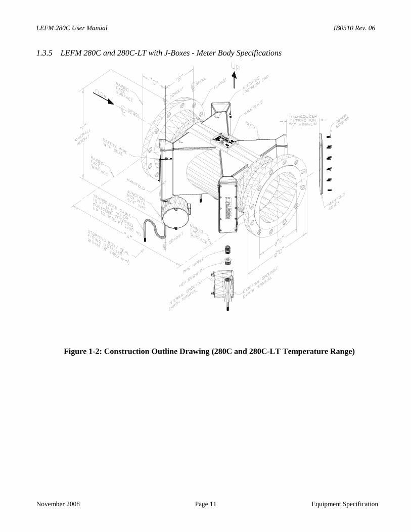
1.3.5 LEFM 280C and 280C-LT with J-Boxes - Meter Body Specifications
Figure 1-2: Construction Outline Drawing (280C and 280C-LT Temperature Range)
IB0510 Rev. 06 LEFM 280C User Manual
Equipment Specification Page 12 November 2008
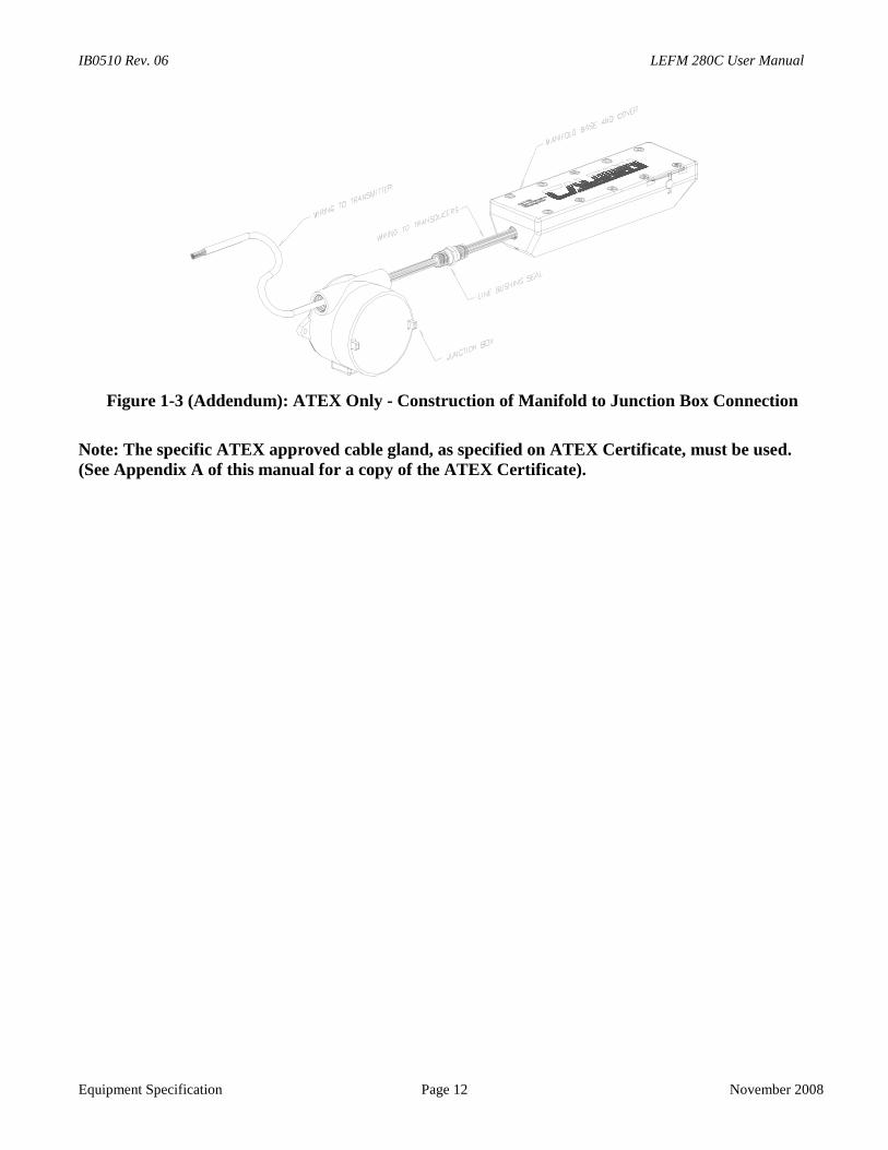
Figure 1-3 (Addendum): ATEX Only - Construction of Manifold to Junction Box Connection
Note: The specific ATEX approved cable gland, as specified on ATEX Certificate, must be used.(See Appendix A of this manual for a copy of the ATEX Certificate).
LEFM 280C User Manual IB0510 Rev. 06
November 2008 Page 13 Equipment Specification
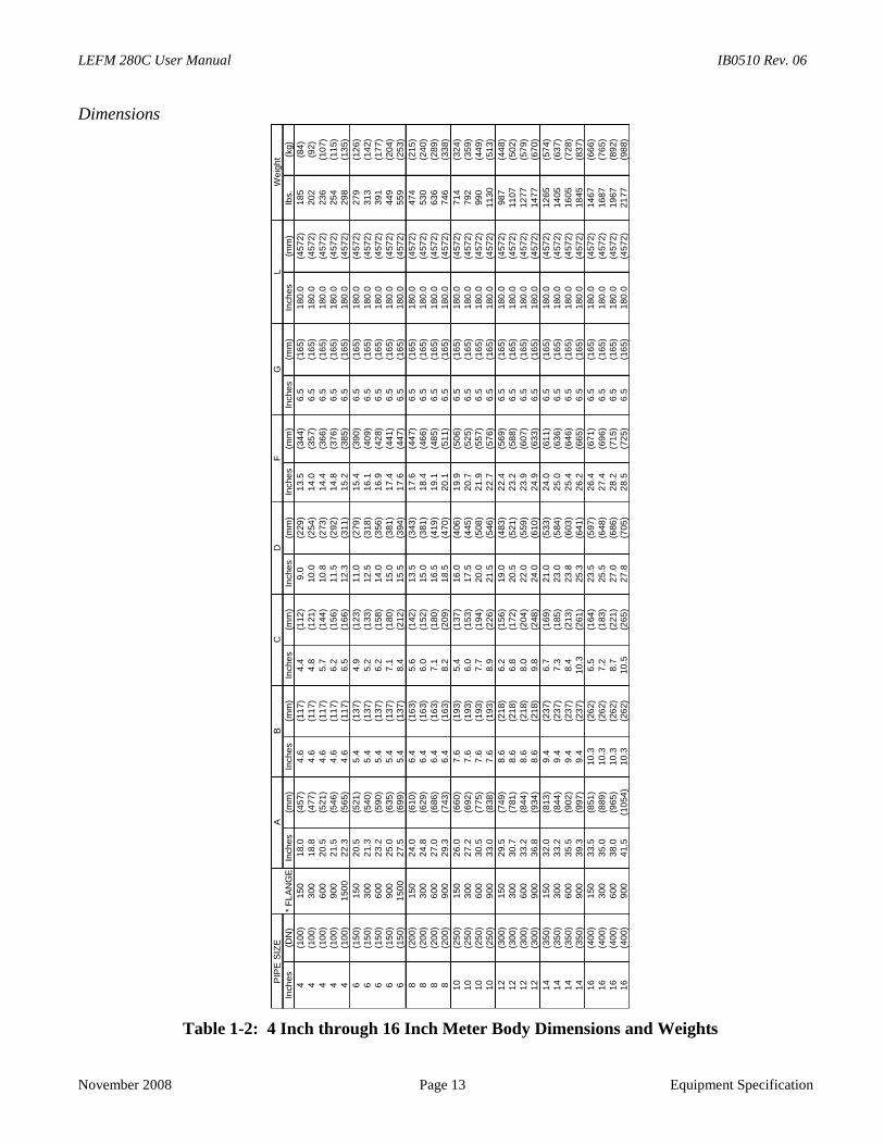
Dimensions
Table 1-2: 4 Inch through 16 Inch Meter Body Dimensions and Weights
Inch
es
(DN
)In
ches
(mm
)In
che
s(m
m)
Inch
es
(mm
)In
che
s(m
m)
Inche
s(m
m)
Inche
s(m
m)
Inch
es
(mm
)lb
s.(k
g)
4(1
00)
150
18.0
(457
)4
.6(1
17)
4.4
(112
)9
.0(2
29
)1
3.5
(34
4)
6.5
(16
5)
180
.0(4
57
2)
18
5(8
4)
4(1
00)
300
18.8
(477
)4
.6(1
17)
4.8
(121
)10
.0(2
54
)1
4.0
(35
7)
6.5
(16
5)
180
.0(4
57
2)
20
2(9
2)
4(1
00)
600
20.5
(521
)4
.6(1
17)
5.7
(144
)10
.8(2
73
)1
4.4
(36
6)
6.5
(16
5)
180
.0(4
57
2)
23
6(1
07)
4(1
00)
900
21.5
(546
)4
.6(1
17)
6.2
(156
)11
.5(2
92
)1
4.8
(37
6)
6.5
(16
5)
180
.0(4
57
2)
25
4(1
15)
4(1
00)
150
02
2.3
(565
)4
.6(1
17)
6.5
(166
)12
.3(3
11
)1
5.2
(38
5)
6.5
(16
5)
180
.0(4
57
2)
29
8(1
35)
6(1
50)
150
20.5
(521
)5
.4(1
37)
4.9
(123
)11
.0(2
79
)1
5.4
(39
0)
6.5
(16
5)
180
.0(4
57
2)
27
9(1
26)
6(1
50)
300
21.3
(540
)5
.4(1
37)
5.2
(133
)12
.5(3
18
)1
6.1
(40
9)
6.5
(16
5)
180
.0(4
57
2)
31
3(1
42)
6(1
50)
600
23.2
(590
)5
.4(1
37)
6.2
(158
)14
.0(3
56
)1
6.9
(42
8)
6.5
(16
5)
180
.0(4
57
2)
39
1(1
77)
6(1
50)
900
25.0
(635
)5
.4(1
37)
7.1
(180
)15
.0(3
81
)1
7.4
(44
1)
6.5
(16
5)
180
.0(4
57
2)
44
9(2
04)
6(1
50)
150
02
7.5
(699
)5
.4(1
37)
8.4
(212
)15
.5(3
94
)1
7.6
(44
7)
6.5
(16
5)
180
.0(4
57
2)
55
9(2
53)
8(2
00)
150
24.0
(610
)6
.4(1
63)
5.6
(142
)13
.5(3
43
)1
7.6
(44
7)
6.5
(16
5)
180
.0(4
57
2)
47
4(2
15)
8(2
00)
300
24.8
(629
)6
.4(1
63)
6.0
(152
)15
.0(3
81
)1
8.4
(46
6)
6.5
(16
5)
180
.0(4
57
2)
53
0(2
40)
8(2
00)
600
27.0
(686
)6
.4(1
63)
7.1
(180
)16
.5(4
19
)1
9.1
(48
5)
6.5
(16
5)
180
.0(4
57
2)
63
6(2
89)
8(2
00)
900
29.3
(743
)6
.4(1
63)
8.2
(209
)18
.5(4
70
)2
0.1
(51
1)
6.5
(16
5)
180
.0(4
57
2)
74
6(3
38)
10
(25
0)
150
26.0
(660
)7
.6(1
93)
5.4
(137
)16
.0(4
06
)1
9.9
(50
6)
6.5
(16
5)
180
.0(4
57
2)
71
4(3
24)
10
(25
0)
300
27.2
(692
)7
.6(1
93)
6.0
(153
)17
.5(4
45
)2
0.7
(52
5)
6.5
(16
5)
180
.0(4
57
2)
79
2(3
59)
10
(25
0)
600
30.5
(775
)7
.6(1
93)
7.7
(194
)20
.0(5
08
)2
1.9
(55
7)
6.5
(16
5)
180
.0(4
57
2)
99
0(4
49)
10
(25
0)
900
33.0
(838
)7
.6(1
93)
8.9
(226
)21
.5(5
46
)2
2.7
(57
6)
6.5
(16
5)
180
.0(4
57
2)
11
30
(51
3)
12
(30
0)
150
29.5
(749
)8
.6(2
18)
6.2
(156
)19
.0(4
83
)2
2.4
(56
9)
6.5
(16
5)
180
.0(4
57
2)
98
7(4
48)
12
(30
0)
300
30.7
(781
)8
.6(2
18)
6.8
(172
)20
.5(5
21
)2
3.2
(58
8)
6.5
(16
5)
180
.0(4
57
2)
11
07
(50
2)
12
(30
0)
600
33.2
(844
)8
.6(2
18)
8.0
(204
)22
.0(5
59
)2
3.9
(60
7)
6.5
(16
5)
180
.0(4
57
2)
12
77
(57
9)
12
(30
0)
900
36.8
(934
)8
.6(2
18)
9.8
(248
)24
.0(6
10
)2
4.9
(63
3)
6.5
(16
5)
180
.0(4
57
2)
14
77
(67
0)
14
(35
0)
150
32.0
(813
)9
.4(2
37)
6.7
(169
)21
.0(5
33
)2
4.0
(61
1)
6.5
(16
5)
180
.0(4
57
2)
12
65
(57
4)
14
(35
0)
300
33.2
(844
)9
.4(2
37)
7.3
(185
)23
.0(5
84
)2
5.0
(63
6)
6.5
(16
5)
180
.0(4
57
2)
14
05
(63
7)
14
(35
0)
600
35.5
(902
)9
.4(2
37)
8.4
(213
)23
.8(6
03
)2
5.4
(64
6)
6.5
(16
5)
180
.0(4
57
2)
16
05
(72
8)
14
(35
0)
900
39.3
(997
)9
.4(2
37)
10
.3(2
61
)25
.3(6
41
)2
6.2
(66
5)
6.5
(16
5)
180
.0(4
57
2)
18
45
(83
7)
16
(40
0)
150
33.5
(851
)10
.3(2
62)
6.5
(164
)23
.5(5
97
)2
6.4
(67
1)
6.5
(16
5)
180
.0(4
57
2)
14
67
(66
6)
16
(40
0)
300
35.0
(889
)10
.3(2
62)
7.2
(183
)25
.5(6
48
)2
7.4
(69
6)
6.5
(16
5)
180
.0(4
57
2)
16
87
(76
5)
16
(40
0)
600
38.0
(965
)10
.3(2
62)
8.7
(221
)27
.0(6
86
)2
8.2
(71
5)
6.5
(16
5)
180
.0(4
57
2)
19
67
(89
2)
16
(40
0)
900
41.5
(10
54
)10
.3(2
62)
10
.5(2
65
)27
.8(7
05
)2
8.5
(72
5)
6.5
(16
5)
180
.0(4
57
2)
21
77
(98
8)
We
igh
tB
CD
GL
PIP
ES
IZE
*F
LA
NG
E
AF
IB0510 Rev. 06 LEFM 280C User Manual
Equipment Specification Page 14 November 2008
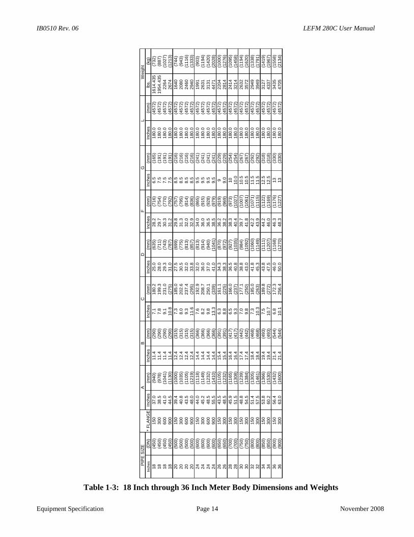
Table 1-3: 18 Inch through 36 Inch Meter Body Dimensions and Weights
Inch
es
(DN
)In
ches
(mm
)In
che
s(m
m)
Inch
es
(mm
)In
ches
(mm
)In
ches
(mm
)In
che
s(m
m)
Inch
es
(mm
)lb
s.
(kg)
18
(45
0)
150
37
.0(9
40
)1
1.4
(29
0)
7.1
180
.22
5.0
(63
5)
28
.2(7
16)
6.5
(165
)1
80
.0(4
57
2)
16
14
.435
(732
)18
(45
0)
300
38
.5(9
78
)1
1.4
(29
0)
7.8
199
.32
8.0
(71
1)
29
.7(7
54)
7.5
(191
)1
80
.0(4
57
2)
19
54
.435
(887
)18
(45
0)
600
41
.0(1
041
)1
1.4
(29
0)
9.1
231
.02
9.3
(74
3)
30
.3(7
70)
7.5
(191
)1
80
.0(4
57
2)
226
4(1
027
)18
(45
0)
900
44
.5(1
130
)1
1.4
(29
0)
10.8
(27
5)
31
.0(7
87)
31
.2(7
92)
7.5
(191
)1
80
.0(4
57
2)
267
4(1
213
)
20
(50
0)
150
39
.4(1
000
)1
2.4
(31
5)
7.3
185
.02
7.5
(69
9)
29
.8(7
57)
8.5
(216
)1
80
.0(4
57
2)
164
0(7
44
)20
(50
0)
300
40
.8(1
035
)1
2.4
(31
5)
8.0
202
.63
0.5
(77
5)
31
.3(7
95)
8.5
(216
)1
80
.0(4
57
2)
208
0(9
43
)20
(50
0)
600
43
.5(1
105
)1
2.4
(31
5)
9.3
237
.43
2.0
(81
3)
32
.0(8
14)
8.5
(216
)1
80
.0(4
57
2)
246
0(1
116
)20
(50
0)
900
48
.0(1
219
)1
2.4
(31
5)
11.6
(29
5)
33
.8(8
57)
32
.9(8
36)
8.5
(216
)1
80
.0(4
57
2)
294
0(1
333
)
24
(60
0)
150
44
.0(1
118
)1
4.4
(36
6)
7.6
192
.93
2.0
(81
3)
34
.0(8
65)
9.5
(241
)1
80
.0(4
57
2)
199
1(9
03
)24
(60
0)
300
45
.2(1
149
)1
4.4
(36
6)
8.2
208
.73
6.0
(91
4)
36
.0(9
15)
9.5
(241
)1
80
.0(4
57
2)
263
1(1
194
)24
(60
0)
600
48
.5(1
232
)1
4.4
(36
6)
9.8
250
.13
7.0
(94
0)
36
.5(9
28)
9.5
(241
)1
80
.0(4
57
2)
313
1(1
420
)24
(60
0)
900
55
.5(1
410
)1
4.4
(36
6)
13.3
(33
9)
41
.0(1
04
1)
38
.5(9
79)
9.5
(241
)1
80
.0(4
57
2)
447
1(2
028
)
26
(65
0)
150
43
.5(1
105
)1
5.4
(39
1)
6.3
161
.13
4.3
(87
0)
36
.2(9
19)
9(2
29
)1
80
.0(4
57
2)
220
4(1
000
)26
(65
0)
300
48
.5(1
232
)1
5.4
(39
1)
8.8
(22
5)
38
.3(9
72)
38
.2(9
69)
9.0
(229
)1
80
.0(4
57
2)
281
4(1
276
)
28
(70
0)
150
45
.9(1
165
)1
6.4
(41
7)
6.5
166
.03
6.5
(92
7)
38
.3(9
73)
10
(254
)1
80
.0(4
57
2)
241
4(1
095
)28
(70
0)
300
51
.5(1
308
)1
6.4
(41
7)
9.3
(23
7)
40
.8(1
03
5)
40
.4(1
02
7)
10
.0(2
54
)1
80
.0(4
57
2)
321
4(1
458
)
30
(75
0)
150
48
.8(1
239
)1
7.4
(44
2)
7.0
177
.13
8.8
(98
4)
39
.7(1
00
7)
10
.5(2
67
)1
80
.0(4
57
2)
263
2(1
194
)30
(75
0)
300
54
.5(1
384
)1
7.4
(44
2)
9.8
(25
0)
43
.0(1
09
2)
41
.8(1
06
1)
10
.5(2
67
)1
80
.0(4
57
2)
357
2(1
620
)
32
(80
0)
150
51
.4(1
305
)1
8.4
(46
8)
7.3
185
.04
1.8
(106
0)
42
.2(1
07
1)
11
.5(2
92
)1
80
.0(4
57
2)
294
9(1
338
)32
(80
0)
300
57
.5(1
461
)1
8.4
(46
8)
10.3
(26
3)
45
.3(1
14
9)
43
.9(1
11
5)
11
.5(2
92
)1
80
.0(4
57
2)
394
9(1
791
)
34
(85
0)
150
53
.8(1
366
)1
9.4
(49
3)
7.5
189
.84
3.8
(111
1)
44
.2(1
12
2)
12
.5(3
18
)1
80
.0(4
57
2)
312
7(1
419
)34
(85
0)
300
60
.2(1
530
)1
9.4
(49
3)
10.7
(27
2)
47
.5(1
20
7)
46
.0(1
16
9)
12
.5(3
18
)1
80
.0(4
57
2)
433
7(1
967
)
36
(90
0)
150
56
.4(1
432
)2
1.4
(54
4)
6.8
172
.34
6.0
(116
8)
46
.3(1
17
6)
13
(330
)1
80
.0(4
57
2)
343
5(1
558
)36
(90
0)
300
63
.0(1
600
)2
1.4
(54
4)
10.1
256
.45
0.0
(127
0)
48
.3(1
22
7)
13
(330
)1
80
.0(4
57
2)
470
5(2
134
)
PIP
ES
IZE
*F
LA
NG
E
Weig
ht
LG
FD
CB
A
LEFM 280C User Manual IB0510 Rev. 06
November 2008 Page 15
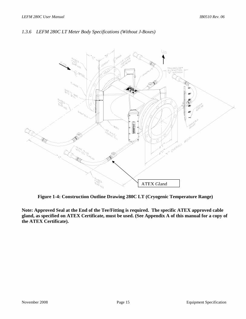
1.3.6 LEFM 280C LT Meter Body Specifications (Without J-Boxes)
Figure 1-4: Construction Outline Drawing 280C L
Note: Approved Seal at the End of the Tee/Fitting is requgland, as specified on ATEX Certificate, must be used. (Sthe ATEX Certificate).
Equipment Specification
T (Cryogenic Temperature Range)
ired. The specific ATEX approved cableee Appendix A of this manual for a copy of
ATEX Gland
IB0510 Rev. 06 LEFM 280C User Manual
Equipment Specification Page 16 November 2008
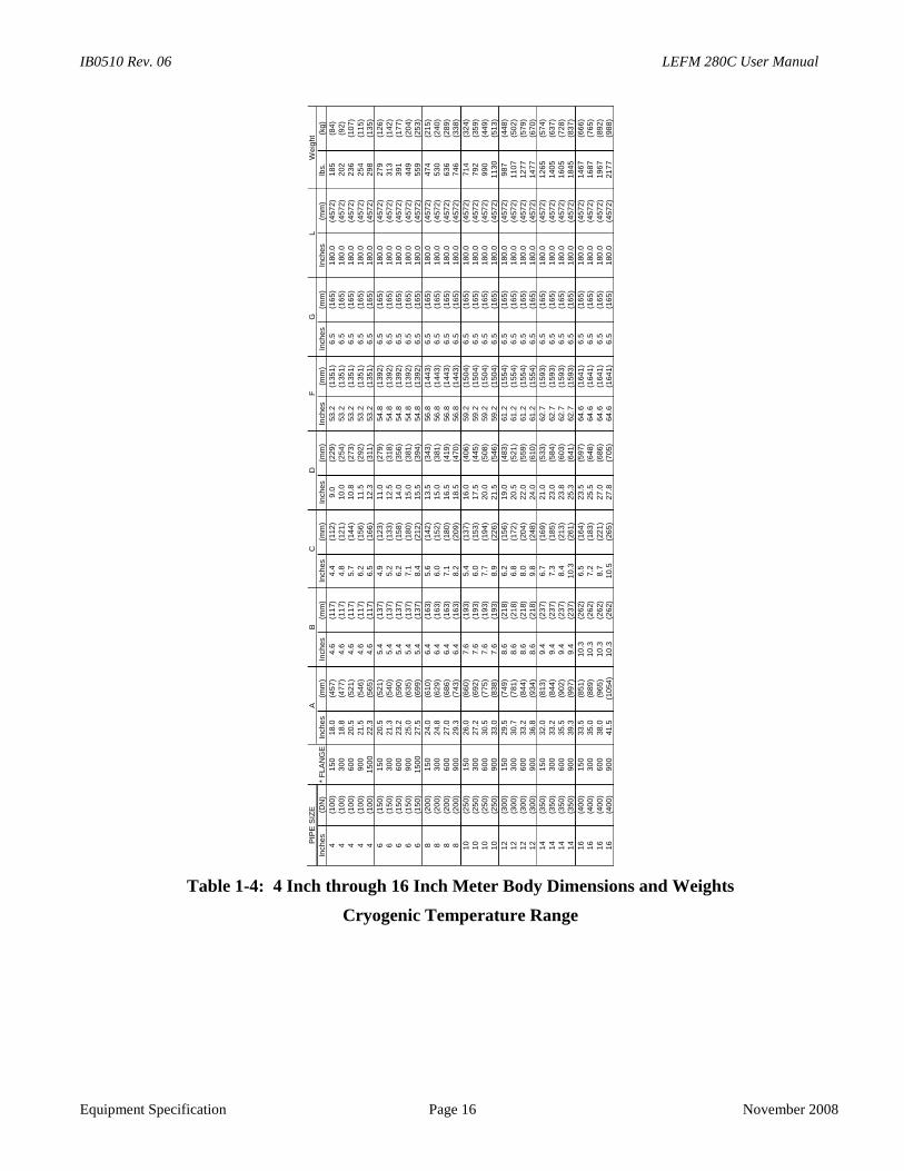
Table 1-4: 4 Inch through 16 Inch Meter Body Dimensions and Weights
Cryogenic Temperature Range
Inch
es
(DN
)In
ch
es
(mm
)In
ch
es
(mm
)In
ch
es
(mm
)In
ch
es
(mm
)In
ch
es
(mm
)In
ch
es
(mm
)In
ch
es
(mm
)lb
s.
(kg)
4(1
00
)1
50
18
.0(4
57
)4.6
(11
7)
4.4
(11
2)
9.0
(229
)53
.2(1
35
1)
6.5
(16
5)
180
.0(4
57
2)
18
5(8
4)
4(1
00
)3
00
18
.8(4
77
)4.6
(11
7)
4.8
(12
1)
10
.0(2
54
)53
.2(1
35
1)
6.5
(16
5)
180
.0(4
57
2)
20
2(9
2)
4(1
00
)6
00
20
.5(5
21
)4.6
(11
7)
5.7
(14
4)
10
.8(2
73
)53
.2(1
35
1)
6.5
(16
5)
180
.0(4
57
2)
23
6(1
07
)4
(10
0)
90
021
.5(5
46
)4.6
(11
7)
6.2
(15
6)
11
.5(2
92
)53
.2(1
35
1)
6.5
(16
5)
180
.0(4
57
2)
25
4(1
15
)4
(10
0)
15
00
22
.3(5
65
)4.6
(11
7)
6.5
(16
6)
12
.3(3
11
)53
.2(1
35
1)
6.5
(16
5)
180
.0(4
57
2)
29
8(1
35
)
6(1
50
)1
50
20
.5(5
21
)5.4
(13
7)
4.9
(12
3)
11
.0(2
79
)54
.8(1
39
2)
6.5
(16
5)
180
.0(4
57
2)
27
9(1
26
)6
(15
0)
30
021
.3(5
40
)5.4
(13
7)
5.2
(13
3)
12
.5(3
18
)54
.8(1
39
2)
6.5
(16
5)
180
.0(4
57
2)
31
3(1
42
)6
(15
0)
60
023
.2(5
90
)5.4
(13
7)
6.2
(15
8)
14
.0(3
56
)54
.8(1
39
2)
6.5
(16
5)
180
.0(4
57
2)
39
1(1
77
)6
(15
0)
90
025
.0(6
35
)5.4
(13
7)
7.1
(18
0)
15
.0(3
81
)54
.8(1
39
2)
6.5
(16
5)
180
.0(4
57
2)
44
9(2
04
)6
(15
0)
15
00
27
.5(6
99
)5.4
(13
7)
8.4
(21
2)
15
.5(3
94
)54
.8(1
39
2)
6.5
(16
5)
180
.0(4
57
2)
55
9(2
53
)
8(2
00
)1
50
24
.0(6
10
)6.4
(16
3)
5.6
(14
2)
13
.5(3
43
)56
.8(1
44
3)
6.5
(16
5)
180
.0(4
57
2)
47
4(2
15
)8
(20
0)
30
024
.8(6
29
)6.4
(16
3)
6.0
(15
2)
15
.0(3
81
)56
.8(1
44
3)
6.5
(16
5)
180
.0(4
57
2)
53
0(2
40
)8
(20
0)
60
027
.0(6
86
)6.4
(16
3)
7.1
(18
0)
16
.5(4
19
)56
.8(1
44
3)
6.5
(16
5)
180
.0(4
57
2)
63
6(2
89
)8
(20
0)
90
029
.3(7
43
)6.4
(16
3)
8.2
(20
9)
18
.5(4
70
)56
.8(1
44
3)
6.5
(16
5)
180
.0(4
57
2)
74
6(3
38
)
10
(25
0)
15
026
.0(6
60
)7.6
(19
3)
5.4
(13
7)
16
.0(4
06
)59
.2(1
50
4)
6.5
(16
5)
180
.0(4
57
2)
71
4(3
24
)1
0(2
50
)3
00
27
.2(6
92
)7.6
(19
3)
6.0
(15
3)
17
.5(4
45
)59
.2(1
50
4)
6.5
(16
5)
180
.0(4
57
2)
79
2(3
59
)1
0(2
50
)6
00
30
.5(7
75
)7.6
(19
3)
7.7
(19
4)
20
.0(5
08
)59
.2(1
50
4)
6.5
(16
5)
180
.0(4
57
2)
99
0(4
49
)1
0(2
50
)9
00
33
.0(8
38
)7.6
(19
3)
8.9
(22
6)
21
.5(5
46
)59
.2(1
50
4)
6.5
(16
5)
180
.0(4
57
2)
11
30
(51
3)
12
(30
0)
15
029
.5(7
49
)8.6
(21
8)
6.2
(15
6)
19
.0(4
83
)61
.2(1
55
4)
6.5
(16
5)
180
.0(4
57
2)
98
7(4
48
)1
2(3
00
)3
00
30
.7(7
81
)8.6
(21
8)
6.8
(17
2)
20
.5(5
21
)61
.2(1
55
4)
6.5
(16
5)
180
.0(4
57
2)
11
07
(50
2)
12
(30
0)
60
033
.2(8
44
)8.6
(21
8)
8.0
(20
4)
22
.0(5
59
)61
.2(1
55
4)
6.5
(16
5)
180
.0(4
57
2)
12
77
(57
9)
12
(30
0)
90
036
.8(9
34
)8.6
(21
8)
9.8
(24
8)
24
.0(6
10
)61
.2(1
55
4)
6.5
(16
5)
180
.0(4
57
2)
14
77
(67
0)
14
(35
0)
15
032
.0(8
13
)9.4
(23
7)
6.7
(16
9)
21
.0(5
33
)62
.7(1
59
3)
6.5
(16
5)
180
.0(4
57
2)
12
65
(57
4)
14
(35
0)
30
033
.2(8
44
)9.4
(23
7)
7.3
(18
5)
23
.0(5
84
)62
.7(1
59
3)
6.5
(16
5)
180
.0(4
57
2)
14
05
(63
7)
14
(35
0)
60
035
.5(9
02
)9.4
(23
7)
8.4
(21
3)
23
.8(6
03
)62
.7(1
59
3)
6.5
(16
5)
180
.0(4
57
2)
16
05
(72
8)
14
(35
0)
90
039
.3(9
97
)9.4
(23
7)
10.3
(26
1)
25
.3(6
41
)62
.7(1
59
3)
6.5
(16
5)
180
.0(4
57
2)
18
45
(83
7)
16
(40
0)
15
033
.5(8
51
)1
0.3
(26
2)
6.5
(16
4)
23
.5(5
97
)64
.6(1
64
1)
6.5
(16
5)
180
.0(4
57
2)
14
67
(66
6)
16
(40
0)
30
035
.0(8
89
)1
0.3
(26
2)
7.2
(18
3)
25
.5(6
48
)64
.6(1
64
1)
6.5
(16
5)
180
.0(4
57
2)
16
87
(76
5)
16
(40
0)
60
038
.0(9
65
)1
0.3
(26
2)
8.7
(22
1)
27
.0(6
86
)64
.6(1
64
1)
6.5
(16
5)
180
.0(4
57
2)
19
67
(89
2)
16
(40
0)
90
041
.5(1
054
)1
0.3
(26
2)
10.5
(26
5)
27
.8(7
05
)64
.6(1
64
1)
6.5
(16
5)
180
.0(4
57
2)
21
77
(98
8)
We
ight
BC
DG
LP
IPE
SIZ
E
*F
LA
NG
E
AF
LEFM 280C User Manual IB0510 Rev. 06
November 2008 Page 17 Installation
2.0 INSTALLATIONThe transmitters and meter body of the LEFM 280C are shipped as a matched set. The exact physicalproperties, acoustic properties, and calibration of the meter body are pre-programmed into the transmitter.When installing multiple units ensure that the transmitters and meter body remain together. Inaddition, it is essential that the transmitter for Plane A (Paths 1 – 4) and Plane B (Paths 5 – 8) areconnected to the correct junction boxes on the meter body.
280C LT units outfitted for cryogenic temperatures will have short cables with connectors attachedto the meter body. The mating cables are attached to the transmitters. These are keyed such thatthe connections for transmitter A & B can not be cross connected. The connections in Table 2-1 &Table 2-2 are only for reference when using cables with connectors.
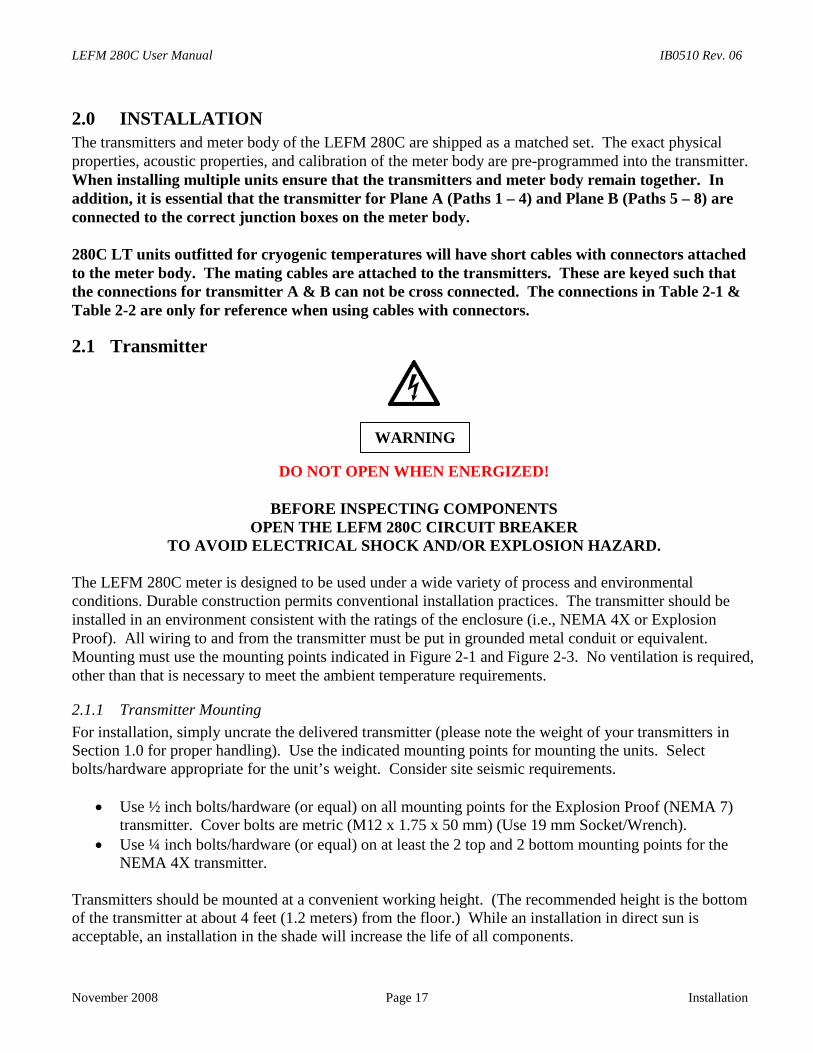
2.1 Transmitter
DO NOT OPEN WHEN ENERGIZED!
BEFORE INSPECTING COMPONENTSOPEN THE LEFM 280C CIRCUIT BREAKER
TO AVOID ELECTRICAL SHOCK AND/OR EXPLOSION HAZARD.
The LEFM 280C meter is designed to be used under a wide variety of process and environmentalconditions. Durable construction permits conventional installation practices. The transmitter should beinstalled in an environment consistent with the ratings of the enclosure (i.e., NEMA 4X or ExplosionProof). All wiring to and from the transmitter must be put in grounded metal conduit or equivalent.Mounting must use the mounting points indicated in Figure 2-1 and Figure 2-3. No ventilation is required,other than that is necessary to meet the ambient temperature requirements.
2.1.1 Transmitter Mounting
For installation, simply uncrate the delivered transmitter (please note the weight of your transmitters inSection 1.0 for proper handling). Use the indicated mounting points for mounting the units. Selectbolts/hardware appropriate for the unit’s weight. Consider site seismic requirements.
Use ½ inch bolts/hardware (or equal) on all mounting points for the Explosion Proof (NEMA 7)transmitter. Cover bolts are metric (M12 x 1.75 x 50 mm) (Use 19 mm Socket/Wrench).
Use ¼ inch bolts/hardware (or equal) on at least the 2 top and 2 bottom mounting points for theNEMA 4X transmitter.
Transmitters should be mounted at a convenient working height. (The recommended height is the bottomof the transmitter at about 4 feet (1.2 meters) from the floor.) While an installation in direct sun isacceptable, an installation in the shade will increase the life of all components.
WARNING
IB0510 Rev. 06 LEFM 280C User Manual
Installation Page 18 November 2008
2.1.2 Field Terminations
On units outfitted for cryogenic temperatures glanded cables with connectors are supplied. In this caseconduit is not required for the signal cables. The connectors are keyed and can only be connected oneway. The tables below are consistent with these cable and are a good reference when troubleshootingproblems.
The wiring should be routed to each transmitter in separate shielded conduit that meets site environmentspecifications. Cables for transmitter A should be routed separately from the cables for transmitter B. Allterminations should be made according to Table 2-1 through Table 2-6. For full environmentaltemperature range all wiring (conductors) should be rated for a minimum of 194°F (90°C). All supplywiring must be rated to 300 volts AC (18 AWG). Equipment must be installed by a licensed electrician, inaccordance with NEC/CEC or local codes. As a minimum, a disconnect switch should be installed beforeand near each transmitter’s power input. The external disconnect device must be an approved device ratedfor the supply voltages and is rated to 3 Amps (or 15 Amps for the 24 Volts DC) and provide a minimumof 3.0 mm spacing.
Explosion Proof enclosures must be installed with rigid conduit with stopping boxes / seal fittings installedwithin 3 inches (75 mm) of the transmitter enclosure.
The Figure 2-1, Figure 2-2, Figure 2-3, and Figure 2-4 illustrate the conduit connections for the LEFM280C Transmitter and the transmitter layout.
2.1.3 Terminations - Digital Signals
Terminal block TB5 has all the digital outputs and inputs. These are listed as follows:
TB5-1 Volume pulses (0-5 Volts)TB5-2 Volume pulses (0-5 Volts)TB5-3 Volume pulses (Quadrature 0-5 Volts) See Section 2.2.3TB5-4 Flow direction (5 Volts forward, 0 Volts reverse)TB5-5 Status (5 Volts normal, 0 Volts alarm)TB5-7 Ground, return for all signalsTB5-9 External trigger (GSS signal) this is used and is for exceptional site installations. Use of this feature
is ONLY done with Cameron input.
2.1.4 Grounding/Earthing (Meter Body and Transmitter)
The meter body and transmitter have grounding/earthing points available. There are grounding points onthe inside of the junction box at the meter body and on the outside of the junction box and the manifold.There are grounding points on the inside and outside of the transmitter enclosure. For ATEX applications,both grounding points must be used. Follow all other site guidelines regarding grounding/earthing. SeeFigure 1-1 and Figure 1-2 for earthing points on the meter body.
LEFM 280C User Manual IB0510 Rev. 06
November 2008 Page 19 Installation
2.2 Flow Meter Body
DO NOT OPEN WHEN ENERGIZED!
BEFORE INSPECTING COMPONENTSOPEN THE LEFM 280C CIRCUIT BREAKER
TO AVOID ELECTRICAL SHOCK AND/OR EXPLOSION HAZARD.
No external supports or special mounting pads are specifically required or recommended for the LEFM280C meter body. However, the piping immediately upstream and downstream of the flow meter shouldbe well supported in accordance with good piping practices and site seismic requirements. See Table 1-2and Table 1-3 for weights and sizes of the LEFM 280C Flow Meter. The flow meter body can be installedin either horizontal or vertical piping runs. When it is installed in horizontal piping, the acoustic pathsshould be horizontal to decrease the likelihood of the accumulation of water, gas, or debris in the sensorwells.
The flow meter body is typically fabricated of stainless steel, carbon steel, or duplex steel, depending oncustomer requirements. The flow meter is designed such that it is as strong as or stronger than pipe andflanges of the same schedule, pressure class and material. Site stress analysis can conservatively treat themeter as equivalent pipe.
2.2.1 Meter Body Terminations
The meter body terminations are defined in Table 2-1. For hazardous environments, the connections fromthe meter body junction box to the electronics must be through rigid conduit or approved equals withstopping boxes/seal fittings installed within 18 inches (450 mm) of the junction box(es). (For ATEX seethe certificate for the conditions for safe use).
2.2.2 Upstream and Downstream Piping
It is recommended that the LEFM 280C meter body be installed downstream of at least 5 diameters ofstraight pipe of the same nominal diameter as the meter for most installations. In cases were there isextreme piping asymmetries (partially open valve, asymmetric reducer, etc.) then 15 diameters of straightpipe of the same nominal diameter should be used. Downstream there should be at least 3 diameters ofstraight pipe of the same nominal diameter as the meter.
2.2.3 Flow Direction
The LEFM 280C Meter is a bidirectional meter with a quadrature pulse output available to indicatedirection of flow (Reference Table 2-5). Pulse output A leading pulse output B by 90° indicates forwardflow while pulse output B leading pulse output A by 90° indicates reverse flow with respect to the flowarrow of the nameplate. To ensure that the flow indication is displayed correctly, the fluid should flow inthe same direction as the arrow on the meter body nameplate.
WARNING
IB0510 Rev. 06 LEFM 280C User Manual
Installation Page 20 November 2008
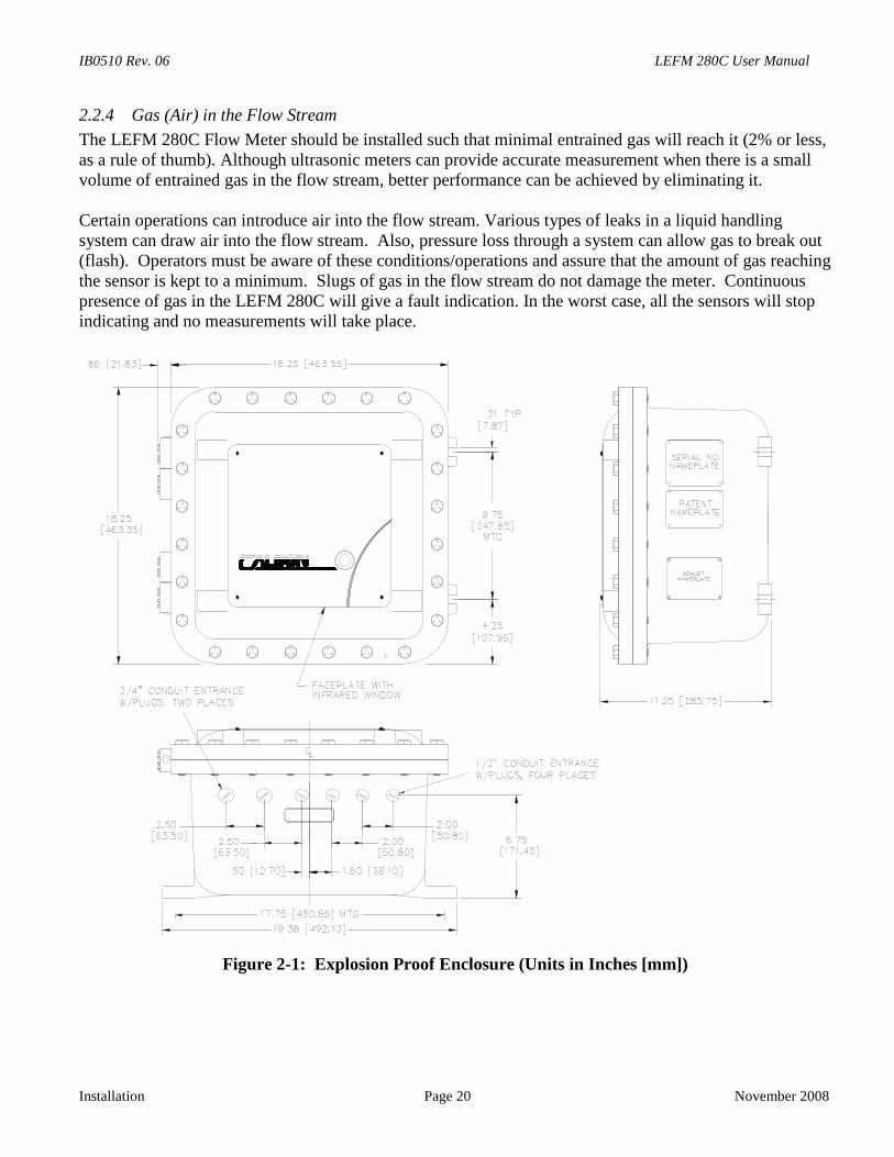
2.2.4 Gas (Air) in the Flow Stream
The LEFM 280C Flow Meter should be installed such that minimal entrained gas will reach it (2% or less,as a rule of thumb). Although ultrasonic meters can provide accurate measurement when there is a smallvolume of entrained gas in the flow stream, better performance can be achieved by eliminating it.
Certain operations can introduce air into the flow stream. Various types of leaks in a liquid handlingsystem can draw air into the flow stream. Also, pressure loss through a system can allow gas to break out(flash). Operators must be aware of these conditions/operations and assure that the amount of gas reachingthe sensor is kept to a minimum. Slugs of gas in the flow stream do not damage the meter. Continuouspresence of gas in the LEFM 280C will give a fault indication. In the worst case, all the sensors will stopindicating and no measurements will take place.
Figure 2-1: Explosion Proof Enclosure (Units in Inches [mm])
LEFM 280C User Manual IB0510 Rev. 06
November 2008 Page 21 Installation
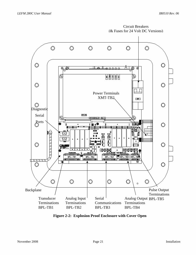
Figure 2-2: Explosion Proof Enclosure with Cover Open
Circuit Breakers(& Fuses for 24 Volt DC Versions)
Power TerminalsXMT-TB2
Backplane
TransducerTerminationsBPL-TB1
Analog InputTerminationsBPL-TB2
Analog OutputTerminationsBPL-TB4
SerialCommunicationsBPL-TB3
Pulse OutputTerminationsBPL-TB5
Diagnostic
Serial
Ports
IB0510 Rev. 06 LEFM 280C User
Installation Page 22 Nov
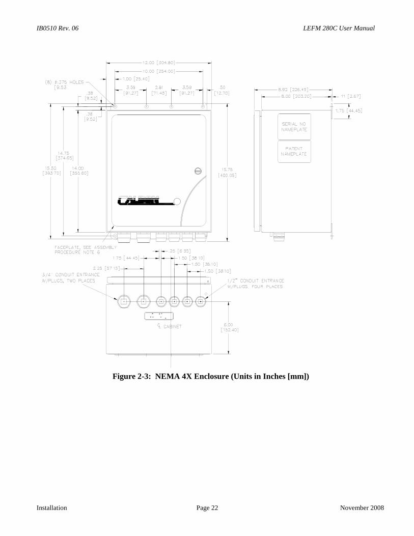
Figure 2-3: NEMA 4X Enclosure (Units in Inches [mm])
Manual
ember 2008
LEFM 280C User Manual IB0510 Rev. 06
November 2008 Page 23 Installation
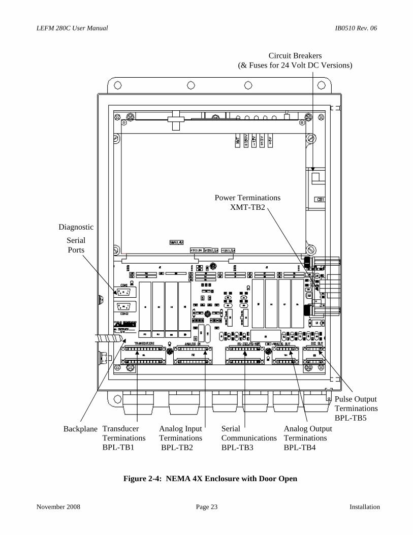
Figure 2-4: NEMA 4X Enclosure with Door Open
Circuit Breakers(& Fuses for 24 Volt DC Versions)
Backplane
Power TerminationsXMT-TB2
TransducerTerminationsBPL-TB1
Analog InputTerminationsBPL-TB2
Analog OutputTerminationsBPL-TB4
SerialCommunicationsBPL-TB3
Pulse OutputTerminationsBPL-TB5
Diagnostic
SerialPorts
IB0510 Rev. 06 LEFM 280C User Manual
Installation Page 24 November 2008
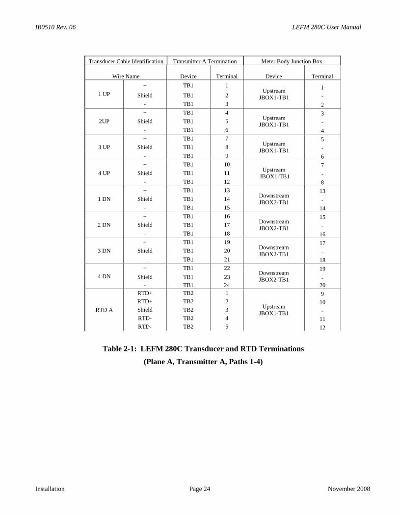
Transducer Cable Identification Transmitter A Termination Meter Body Junction Box
Wire Name Device Terminal Device Terminal
1 UP
+ TB1 1Upstream
JBOX1-TB1
1
Shield TB1 2 -
- TB1 3 2
2UP
+ TB1 4Upstream
JBOX1-TB1
3
Shield TB1 5 -
- TB1 6 4
3 UP
+ TB1 7Upstream
JBOX1-TB1
5
Shield TB1 8 -
- TB1 9 6
4 UP
+ TB1 10Upstream
JBOX1-TB1
7
Shield TB1 11 -
- TB1 12 8
1 DN
+ TB1 13DownstreamJBOX2-TB1
13
Shield TB1 14 -
- TB1 15 14
2 DN
+ TB1 16DownstreamJBOX2-TB1
15
Shield TB1 17 -
- TB1 18 16
3 DN
+ TB1 19DownstreamJBOX2-TB1
17
Shield TB1 20 -
- TB1 21 18
4 DN
+ TB1 22DownstreamJBOX2-TB1
19
Shield TB1 23 -
- TB1 24 20
RTD A
RTD+ TB2 1
UpstreamJBOX1-TB1
9
RTD+ TB2 2 10
Shield TB2 3 -
RTD- TB2 4 11
RTD- TB2 5 12
Table 2-1: LEFM 280C Transducer and RTD Terminations
(Plane A, Transmitter A, Paths 1-4)
LEFM 280C User Manual IB0510 Rev. 06
November 2008 Page 25 Installation
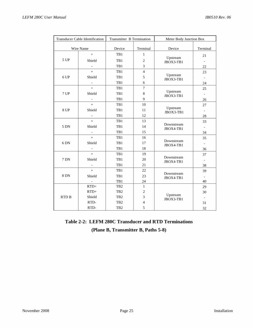
Transducer Cable Identification Transmitter B Termination Meter Body Junction Box
Wire Name Device Terminal Device Terminal
5 UP
+ TB1 1Upstream
JBOX3-TB1
21
Shield TB1 2 -
- TB1 3 22
6 UP
+ TB1 4Upstream
JBOX3-TB1
23
Shield TB1 5 -
- TB1 6 24
7 UP
+ TB1 7Upstream
JBOX3-TB1
25
Shield TB1 8 -
- TB1 9 26
8 UP
+ TB1 10Upstream
JBOX3-TB1
27
Shield TB1 11 -
- TB1 12 28
5 DN
+ TB1 13DownstreamJBOX4-TB1
33
Shield TB1 14 -
- TB1 15 34
6 DN
+ TB1 16DownstreamJBOX4-TB1
35
Shield TB1 17 -
- TB1 18 36
7 DN
+ TB1 19DownstreamJBOX4-TB1
37
Shield TB1 20 -
- TB1 21 38
8 DN
+ TB1 22DownstreamJBOX4-TB1
39
Shield TB1 23 -
- TB1 24 40
RTD B
RTD+ TB2 1
UpstreamJBOX3-TB1
29
RTD+ TB2 2 30
Shield TB2 3 -
RTD- TB2 4 31
RTD- TB2 5 32
Table 2-2: LEFM 280C Transducer and RTD Terminations
(Plane B, Transmitter B, Paths 5-8)
IB0510 Rev. 06 LEFM 280C User Manual
Installation Page 26 November 2008
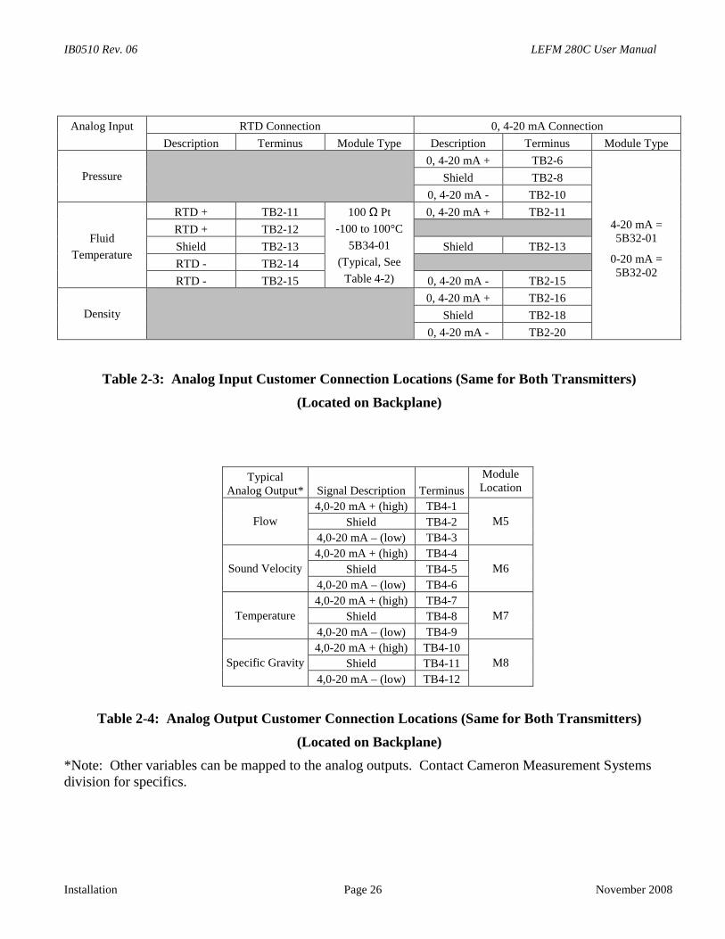
Analog Input RTD Connection 0, 4-20 mA Connection
Description Terminus Module Type Description Terminus Module Type
Pressure
0, 4-20 mA + TB2-6
4-20 mA =5B32-01
0-20 mA =5B32-02
Shield TB2-8
0, 4-20 mA - TB2-10
Fluid
Temperature
RTD + TB2-11 100 Ω Pt
-100 to 100°C
5B34-01
(Typical, See
Table 4-2)
0, 4-20 mA + TB2-11
RTD + TB2-12
Shield TB2-13 Shield TB2-13
RTD - TB2-14
RTD - TB2-15 0, 4-20 mA - TB2-15
Density
0, 4-20 mA + TB2-16
Shield TB2-18
0, 4-20 mA - TB2-20
Table 2-3: Analog Input Customer Connection Locations (Same for Both Transmitters)
(Located on Backplane)
TypicalAnalog Output* Signal Description Terminus
ModuleLocation
Flow
4,0-20 mA + (high) TB4-1
M5Shield TB4-2
4,0-20 mA – (low) TB4-3
Sound Velocity
4,0-20 mA + (high) TB4-4
M6Shield TB4-5
4,0-20 mA – (low) TB4-6
Temperature
4,0-20 mA + (high) TB4-7
M7Shield TB4-8
4,0-20 mA – (low) TB4-9
Specific Gravity
4,0-20 mA + (high) TB4-10
M8Shield TB4-11
4,0-20 mA – (low) TB4-12
Table 2-4: Analog Output Customer Connection Locations (Same for Both Transmitters)
(Located on Backplane)
*Note: Other variables can be mapped to the analog outputs. Contact Cameron Measurement Systemsdivision for specifics.
LEFM 280C User Manual IB0510 Rev. 06
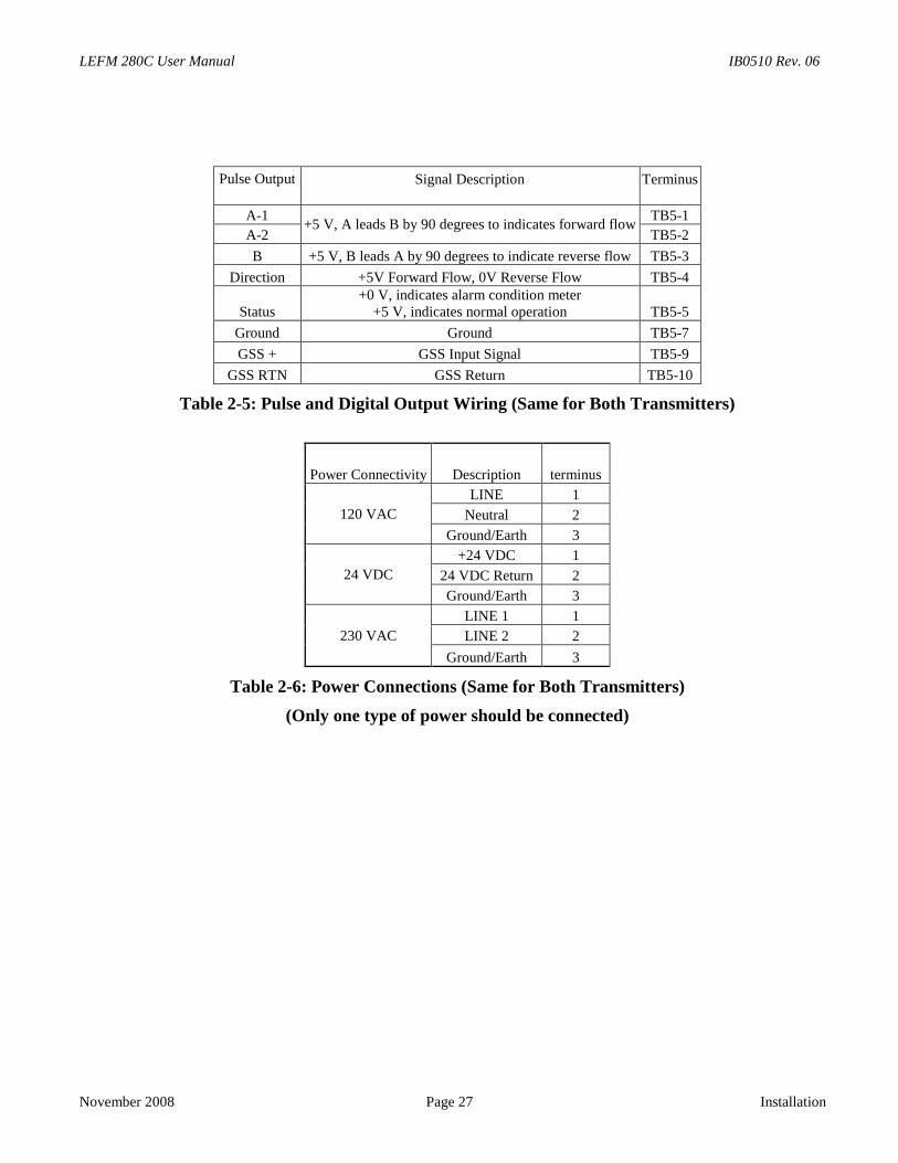
November 2008 Page 27 Installation
Pulse Output Signal Description Terminus
A-1+5 V, A leads B by 90 degrees to indicates forward flow
TB5-1
A-2 TB5-2
B +5 V, B leads A by 90 degrees to indicate reverse flow TB5-3
Direction +5V Forward Flow, 0V Reverse Flow TB5-4
Status+0 V, indicates alarm condition meter
+5 V, indicates normal operation TB5-5
Ground Ground TB5-7
GSS + GSS Input Signal TB5-9
GSS RTN GSS Return TB5-10
Table 2-5: Pulse and Digital Output Wiring (Same for Both Transmitters)
Power Connectivity Description terminus
120 VAC
LINE 1
Neutral 2
Ground/Earth 3
24 VDC
+24 VDC 1
24 VDC Return 2
Ground/Earth 3
230 VAC
LINE 1 1
LINE 2 2
Ground/Earth 3
Table 2-6: Power Connections (Same for Both Transmitters)
(Only one type of power should be connected)
IB0510 Rev. 06 LEFM 280C User Manual
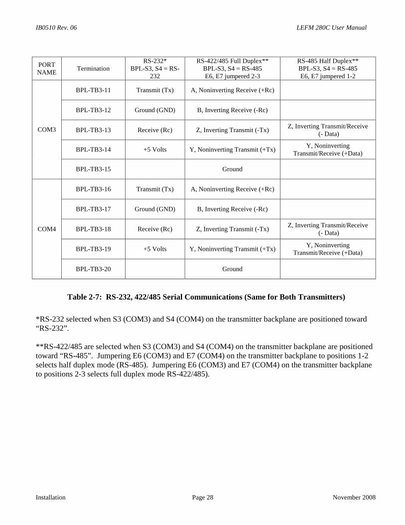
Installation Page 28 November 2008
PORTNAME
TerminationRS-232*
BPL-S3, S4 = RS-232
RS-422/485 Full Duplex**BPL-S3, S4 = RS-485E6, E7 jumpered 2-3
RS-485 Half Duplex**BPL-S3, S4 = RS-485E6, E7 jumpered 1-2
COM3
BPL-TB3-11 Transmit (Tx) A, Noninverting Receive (+Rc)
BPL-TB3-12 Ground (GND) B, Inverting Receive (-Rc)
BPL-TB3-13 Receive (Rc) Z, Inverting Transmit (-Tx)Z, Inverting Transmit/Receive
(- Data)
BPL-TB3-14 +5 Volts Y, Noninverting Transmit (+Tx)Y, Noninverting
Transmit/Receive (+Data)
BPL-TB3-15 Ground
COM4
BPL-TB3-16 Transmit (Tx) A, Noninverting Receive (+Rc)
BPL-TB3-17 Ground (GND) B, Inverting Receive (-Rc)
BPL-TB3-18 Receive (Rc) Z, Inverting Transmit (-Tx)Z, Inverting Transmit/Receive
(- Data)
BPL-TB3-19 +5 Volts Y, Noninverting Transmit (+Tx)Y, Noninverting
Transmit/Receive (+Data)
BPL-TB3-20 Ground
Table 2-7: RS-232, 422/485 Serial Communications (Same for Both Transmitters)
*RS-232 selected when S3 (COM3) and S4 (COM4) on the transmitter backplane are positioned toward“RS-232”.
**RS-422/485 are selected when S3 (COM3) and S4 (COM4) on the transmitter backplane are positionedtoward “RS-485”. Jumpering E6 (COM3) and E7 (COM4) on the transmitter backplane to positions 1-2selects half duplex mode (RS-485). Jumpering E6 (COM3) and E7 (COM4) on the transmitter backplaneto positions 2-3 selects full duplex mode RS-422/485).
LEFM 280C User Manual IB0510 Rev. 06
November 2008 Page 29 Installation
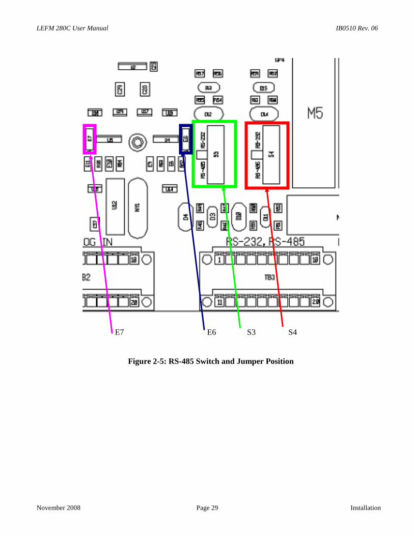
Figure 2-5: RS-485 Switch and Jumper Position
E7 E6 S3 S4
IB0510 Rev. 06 LEFM 280C User Manual
Installation Page 30 November 2008
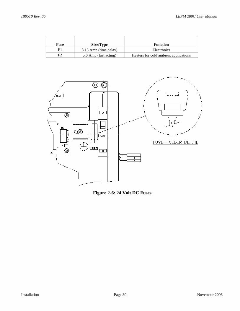
Fuse Size/Type Function
F1 3.15 Amp (time delay) Electronics
F2 5.0 Amp (fast acting) Heaters for cold ambient applications
Figure 2-6: 24 Volt DC Fuses
LEFM 280C User Manual IB0510 Rev. 06
November 2008 Page 31 Installation
2.3 Meter Installation Check-Out
DO NOT OPEN WHEN ENERGIZED!
BEFORE INSPECTING COMPONENTSOPEN THE LEFM 280C CIRCUIT BREAKER
TO AVOID ELECTRICAL SHOCK AND/OR EXPLOSION HAZARD.
The following steps are recommended to checkout a meter’s installation. See Section 5 forTroubleshooting and also reference Caldon Procedure EFP-70.
Step 1: Verify meter’s installation is hydraulically acceptable (horizontal required), and adequate upstreamhydraulics. Upstream pipe diameter is concentric with meter body.
Step 2: Verify all field terminations have proper continuity and isolation from each other and earth. Verifyconnections are good with respect to insulation.
Step 3: Verify electronics turn on (all LEDs lighted).
Step 4: Verify ModBus communications (Use Caldon LEFMLink software or plant computer tocommunicate). Verify meter operation according to Section 5.
Step 5: Verify Analog Outputs, preferably using LEFMLink to force outputs (current and pulses). Forcingoutputs verifies connections to site instruments. Verify observed forced outputs are within 0.1% oncurrent and 0.01% on pulse frequency. Return meter to normal operation.
Step 6: If pipe is full of liquid, verify acoustic signals have Rejects < 2% and SNR (signal to noise ratio) >40. Verify standard deviations of Paths 1, 4, 5 and 8 are less than 6% (for flowing conditions) and verifythe standard deviations of Paths 2, 3, 6 and 7 are less than 4% (for flowing conditions). See Section 5.0
WARNING

IB0510 Rev. 06 LEFM 280C User Manual
Installation Page 32 November 2008
LEFM 280C User Manual IB0510 Rev. 06
November 2008 Page 33 Operation
3.0 OPERATION
3.1 Measuring Velocities
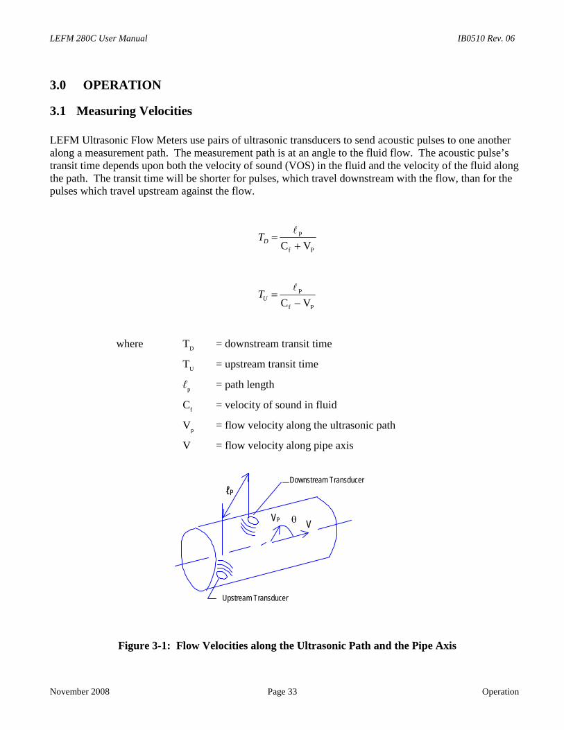
LEFM Ultrasonic Flow Meters use pairs of ultrasonic transducers to send acoustic pulses to one anotheralong a measurement path. The measurement path is at an angle to the fluid flow. The acoustic pulse’stransit time depends upon both the velocity of sound (VOS) in the fluid and the velocity of the fluid alongthe path. The transit time will be shorter for pulses, which travel downstream with the flow, than for thepulses which travel upstream against the flow.
Pf
P
VC
DT
Pf
P
VC
UT
where TD
= downstream transit time
TU
= upstream transit time
ℓp
= path length
Cf
= velocity of sound in fluid
Vp
= flow velocity along the ultrasonic path
V = flow velocity along pipe axis
Figure 3-1: Flow Velocities along the Ultrasonic Path and the Pipe Axis
Downstream Transducer
Upstream Transducer
ℓP
VPV
IB0510 Rev. 06 LEFM 280C User Manual
Operation Page 34 November 2008
When pulses travel upstream and downstream during the same time, the above equations may be treated assimultaneous, and solved for the two unknowns, C
fand V
P.
Solving for VP
and taking into account path angle
TT
T-T
Cos2 UD
DUP
V
Using this method, the velocity measurement V is independent of the velocity of sound and consequentlyis unaffected by variations in flow, temperature, density, chemical composition, etc.
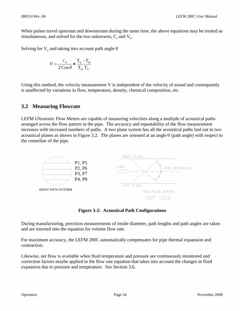
3.2 Measuring Flowrate
LEFM Ultrasonic Flow Meters are capable of measuring velocities along a multiple of acoustical pathsarranged across the flow pattern in the pipe. The accuracy and repeatability of the flow measurementincreases with increased numbers of paths. A two plane system has all the acoustical paths laid out in twoacoustical planes as shown in Figure 3.2. The planes are oriented at an angle (path angle) with respect tothe centerline of the pipe.
Figure 3-2: Acoustical Path Configurations
During manufacturing, precision measurements of inside diameter, path lengths and path angles are takenand are inserted into the equation for volume flow rate.
For maximum accuracy, the LEFM 280C automatically compensates for pipe thermal expansion andcontraction.
Likewise, net flow is available when fluid temperature and pressure are continuously monitored andcorrection factors maybe applied to the flow rate equation that takes into account the changes in fluidexpansion due to pressure and temperature. See Section 3.6.
EIGHT PATH SYSTEM
P1, P5P2, P6P3, P7P4, P8
LEFM 280C User Manual IB0510 Rev. 06
November 2008 Page 35 Operation
3.3 LEFM 280C Transmitter
The LEFM 280C transmitter contains three major functional units, the Acoustic Processing Unit (APU),the Backplane, and the power supply. The Acoustic Processing Unit is a specialized board proprietary toCameron. It is designed to achieve high sampling rates, stable ultrasonic signals, and no zero drift.
The LEFM280C flow meter utilizes two transmitters. Each transmitter independently measures the flowon each plane of the meter.
The APU board performs all control and timing for the generation and measurement of acoustic pulses.The APU board has a microprocessor programmed to perform the following functions:
• Step through the ultrasonic path cycles and test cycles.
• Provide Gain Control for each ultrasonic path.
• Compute flow.
• Compute gross to net conversions
• Generate pulse and analog outputs.
Setups to the APU are provided by a serial link through the backplane.
3.4 LEFM 280C Fault DetectionThe LEFM 280C performs the following automatic fault detection:
• Checks data quality for ultrasonic paths. Evaluates data against thresholds. The data is evaluatedbased on SNR (signal to noise ratio), cross-correlation tests and signal statistics.
• For each ultrasonic path, the APU determines if the path has failed.
• Occasional rejected or bad data does not influence the operation. However, if an ultrasonic pathcontinues to fail, the meter will alert the operators with the "ALARM" status and an error code.
The APU outputs the current status on the serial port and the digital output. The status may be one of thefollowing:
• "NORMAL" status
• "ALARM" status - 1, 2, or 3 paths failed - flow computed with a lower accuracy
• "ALARM" status - all paths failed - flow is set to zero (0)Path status, each ultrasonic path the codes (Reference Caldon ModBus Specifications) are:
• 0 - Path operating normally

IB0510 Rev. 06 LEFM 280C User Manual
Operation Page 36 November 2008
• 1 - Path rejecting data due to low SNR, irregular statistics or failing cross-correlation tests
• 6 - Path sound velocities are inconsistent with thresholds (typically up to 2% spread between pathsis acceptable)
• 7 - Path velocity fails velocity profile test
• 8 - Path velocity inconsistent at low flows
• 10 - Path fails impedance self test
• 11 - Electronics fails clock accuracy test
3.5 Gross to Net Flowrate ConversionNet volumetric flow rate is calculated by correcting gross volumetric flow rate to standard productconditions of 60o F and 0 psig.
Net Flowrate = Gross Flowrate • [Knet,temp • Knet,pres]
The LEFM 280C computes a temperature correction factor and pressure correction factor typically basedon the following references
API Chapter 11.1, Volume I, August 1984 (API Standard 2540), Table 6A – Generalized CrudeOils and JP-4, Correction of Volume to 60 Against API Gravity at 60
API Chapter 11.2.1, Manual of Measurement Standards, March 1990, Compressibility Factors forHydrocarbons: 0-90 API Gravity Range
The required inputs for gross to net calculations include:
• Gross flow rate
• Product temperature
• Product pressure
The specific gravity used for all the gross to net conversions are either hard coded or automaticallycomputed by the LEFM 280C. The automatic calculation is based on API tables, sound velocity,temperature and pressure.

LEFM 280C User Manual IB0510 Rev. 06
November 2008 Page 37 Operation
3.6 Remote Data Communications
The LEFM 280C has three communication ports using the ModBus protocol. See the ModBus Manual formore detail. One serial port is dedicated to the IR serial interface. The second and third serial ports can beaccessed via direct connection (RS-232, or RS-422/RS-485).

IB0510 Rev. 06 LEFM 280C User Manual
Operation Page 38 November 2008
LEFM 280C User Manual IB0510 Rev. 06
N
4.0 MAINTENANCE
4
Tps
Tms
4
T
WARNING: NO OPERATOR ACCESS IS PERMITTED IN THE UNIT. SERVICE SHOULD
ovember 2008
W
.1 Introduction
he purpose of this section is to provide procedures for troubleshooting and maintenance tasks whichersonnel can perform on each LEFM 280C. These procedures may be incorporated into the customer’standard maintenance program.
his section includes procedures for maintaining the LEFM 280C that are designed for a trainedaintenance technician to perform. These procedures may require the maintenance person to reference
chematics, system connection diagrams, and construction outlines in Section 1.0.
.2 General Inspections - Preventative Maintenance Procedures
DO NOT OPEN WHEN ENERGIZED!
BEFORE INSPECTING COMPONENTSOPEN THE LEFM 280C CIRCUIT BREAKER
TO AVOID ELECTRICAL SHOCK AND/OR EXPLOSION HAZARD.
WEAR ANWRIST S
DAMAGING
his procedure covers the inspection of the elect
ONLY BE PERFORMED BY QUALIFIED PERSONNEL.
WARNING
Page 39 Maintenance
ARNING
ESD PROTECTIVETRAP TO AVOIDANY COMPONENTS
ronics unit, transducers, metering sections, and cables.
CAUTION
IB0510 Rev. 06 LEFM 280C User Manual
Maintenance Page 40 November 2008
Enclosure Inspection
Perform the following inspections on each enclosure:
a. Verify electronic unit enclosure has suffered no structural damage. Report any damage to propermaintenance supervisor.
b. Remove dust, dirt, and other soiling from enclosure. If necessary, remove power to the LEFM280C by opening circuit breaker CB1.
c. Inspect access cover gaskets. Clean gaskets and mating surfaces on enclosure with water if theyare dirty; remove any corrosion from mating surfaces. Verify gaskets compress when cover isinstalled and fastened to enclosure.
d. Inspect door latch mechanism.
e. Lubricate door hinges with lubricant specified on enclosure.
f. Inspect enclosure mounting and fastening hardware.
Internal Electronics Inspection
a. If necessary, remove power to the LEFM 280C by opening circuit breaker CB1.
b. Put on an ESD (Electrostatic Discharge) protective wrist strap. Connect ESD protective wrist strapto a known ground; any part of enclosure structure is an acceptable ground.
c. Inspect cable entry points to assure that cable insulation is undamaged. Inspect cables that crosshinges to assure that cable insulation is undamaged.
d. Inspect cable connections for tightness. Clean connections if fouled or corroded with electroniccontact cleaning fluid.
e. Inspect all internal connections and terminals for tightness, clean connectors and terminals if fouledor corroded with electronic contact cleaning fluid.
f. Inspect fuses to assure that they are not damaged or discolored. Replace any damaged or blownfuses.
g. Inspect display panel components (if supplied) and devices for damage. Replace any damagedcomponents. Check all connectors to see that each is properly seated. Check that all devices aresecurely mounted.
h. Inspect acoustical processing unit (APU) components and devices for damage. Check that theprinted circuit boards are properly seated. Check that devices are securely mounted. Clean dustand grime from the surface of all components using compressed air or a PC parts cleaner.
i. Caution: Heater located behind the backplane, allow surface to cool.
j. Clean dust and grime from all surfaces of the enclosure interior walls using compressed air or a PCparts cleaner.
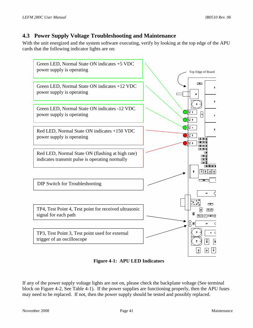
LEFM 280C User Manual IB0510 Rev. 06
November 2008 Page 41 Maintenance
4.3 Power Supply Voltage Troubleshooting and MaintenanceWith the unit energized and the system software executing, verify by looking at the top edge of the APUcards that the following indicator lights are on:
Figure 4-1: APU LED Indicators
If any of the power supply voltage lights are not on, please check the backplane voltage (See terminalblock on Figure 4-2, See Table 4-1). If the power supplies are functioning properly, then the APU fusesmay need to be replaced. If not, then the power supply should be tested and possibly replaced.
Green LED, Normal State ON indicates +5 VDCpower supply is operating
Green LED, Normal State ON indicates +12 VDCpower supply is operating
Green LED, Normal State ON indicates -12 VDCpower supply is operating
Red LED, Normal State ON indicates +150 VDCpower supply is operating
Red LED, Normal State ON (flashing at high rate)indicates transmit pulse is operating normally
DIP Switch for Troubleshooting
TP4, Test Point 4, Test point for received ultrasonicsignal for each path
TP3, Test Point 3, Test point used for externaltrigger of an oscilloscope
Top Edge of Board
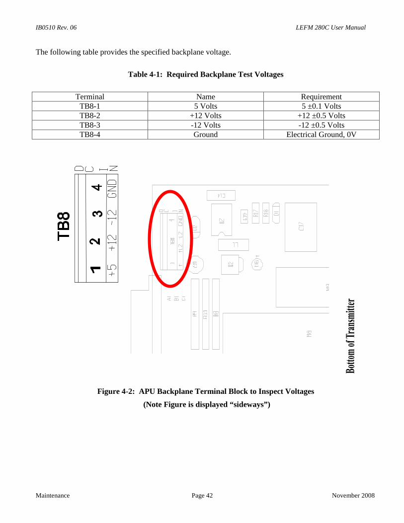
IB0510 Rev. 06 LEFM 280C User Manual
Maintenance Page 42 November 2008
The following table provides the specified backplane voltage.
Table 4-1: Required Backplane Test Voltages
Terminal Name RequirementTB8-1 5 Volts 5 ±0.1 VoltsTB8-2 +12 Volts +12 ±0.5 VoltsTB8-3 -12 Volts -12 ±0.5 VoltsTB8-4 Ground Electrical Ground, 0V
Figure 4-2: APU Backplane Terminal Block to Inspect Voltages
(Note Figure is displayed “sideways”)
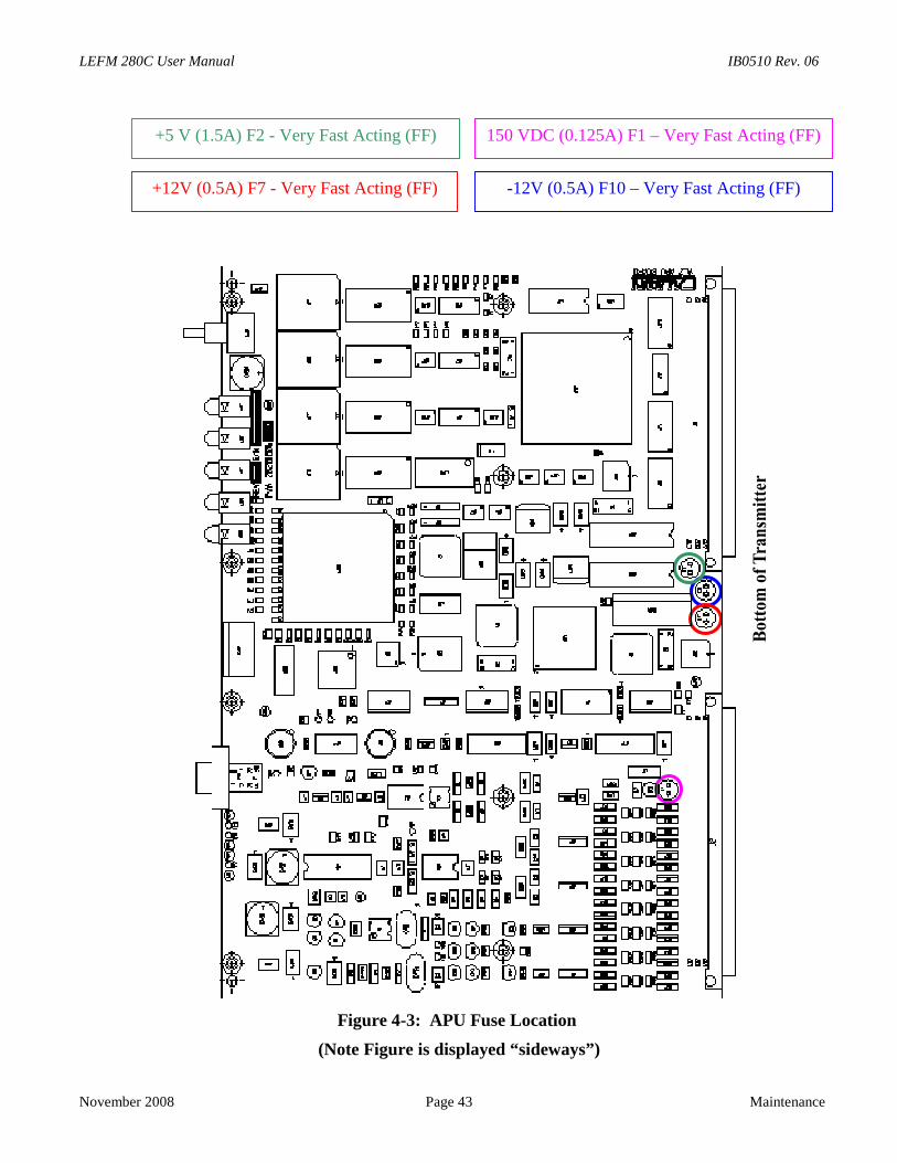
LEFM 280C User Manual IB0510 Rev. 06
November 2008 Page 43 Maintenance
Figure 4-3: APU Fuse Location
(Note Figure is displayed “sideways”)
+5 V (1.5A) F2 - Very Fast Acting (FF) 150 VDC (0.125A) F1 – Very Fast Acting (FF)
+12V (0.5A) F7 - Very Fast Acting (FF) -12V (0.5A) F10 – Very Fast Acting (FF)
IB0510 Rev. 06 LEFM 280C User Manual
Maintenance Page 44 November 2008
4.4 Metering Section and Transducer Cables
Metering Section Inspection
Perform the following inspection and maintenance tasks:
a. Inspect the meter body. Verify meter body has not suffered any damage.
DO NOT OPEN WHEN ENERGIZED!
BEFORE INSPECTING COMPONENTSOPEN THE LEFM 280C CIRCUIT BREAKER
TO AVOID ELECTRICAL SHOCK AND/OR EXPLOSION HAZARD.
b. Check connectors on transducers cables to verify they are undamaged. Clean connectors withelectronic contact cleaner if fouled or corroded. Verify all mounting hardware is secure.
Transducer Cable Inspection
Inspect transducer cables as follows:
DO NOT OPEN WHEN ENERGIZED!
BEFORE INSPECTING COMPONENTSOPEN THE LEFM 280C CIRCUIT BREAKER
TO AVOID ELECTRICAL SHOCK AND/OR EXPLOSION HAZARD.
a. Verify each transducer cable has not suffered any damage. Check connectors on cables at each endto verify each is undamaged. Clean connector with electronic contact cleaner if fouled or corroded.Replace any damaged cable or connector.
b. Disconnect transducer cables from LEFM 280C. Check continuity and isolation of cables.
WARNING
WARNING
LEFM 280C User Manual IB0510 Rev. 06
November 2008 Page 45 Maintenance
c. Reinstall transducer junction box covers after completing all inspections. Be careful not to cut orpinch any wires in junction box while threading on junction box covers.
4.5 Transducer Installation Procedure
Should the unlikely event occur in that a transducer fails, this section defines the transducer replacementand recoupling procedure. The LEFM 280C system may require verification when a transducer is replacedor recoupled.
The transducer should be installed using the following procedures:
Step 1 Power down the LEFM 280C and disconnect the transducer to be replaced from the terminalsin the junction box, (note upstream and downstream junction boxes).
Step 2 Remove manifold cover (remove socket head screws, either M5 or M8 size).
Step 3 Remove transducer internals. Use O-Ratchet socket head (½ inch socket for the ½ inch (12.5mm) transducer housing and ¾ inch socket for the 1 inch (25 mm) transducer housing).Typically 4 inch to 10 inch meter bodies contain ½ inch transducer housings and 12 inch andlarger meter bodies contain 1 inch housings.
Step 4 Replace transducer.
Step 5 Verify the transducer housing is clean and free from dirt.
Step 6 Re-install the transducer internals with fresh lubricant applied to the transducer face.
Step 6a Thread the wires of the transducer though the compression spring and the spacer.
Step 6b Insert the transducer and components into the housing until the parts bottom out.
Step 6c Route the wires though the compression screw and then apply lubricant to the threads. Screwinto the transducer housing and tighten. This will load the compression spring.
Step 7 Connect the new transducer to the junction box terminals.
Step 8 Re-install the manifold and junction box cover. Torque socket head screws, M5 size screws to10 in-lbs (1.1 nm) or the M8 size screws to 30 in-lbs (3.4 nm).
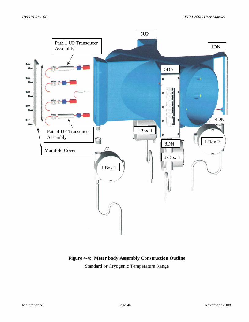
IB0510 Rev. 06 LEFM 280C User Manual
Maintenance Page 46
Figure 4-4: Meter body Assembly
Standard or Cryogenic Tem
Path 1 UP TransducerAssembly
Path 4 UP TransducerAssembly
Manifold Cover
J-Box 1
J
No
Construction Outline
perature Range
5UP
5DN
8DN
-Box 3
J-B
J-Box 4
1DN
4DN
ve
o
x 2mber 2008
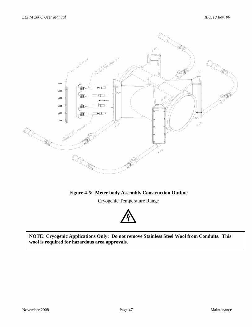
LEFM 280C User Manual IB0510 Rev. 06
No
Figure 4-5: Meter body Assembly Construction Outline
Cryogenic Temperature Range
NOTE: Cryogenic Applications Only: Do not remove Stainless Steel Wool from Conduits. This
vember 2008 Page 47 Maintenance
wool is required for hazardous area approvals.
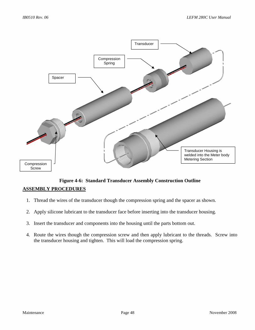
IB0510 Rev. 06 LEFM 280C User Manual
Maintenance Page 48 November 2008
Figure 4-6: Standard Transducer Assembly Construction Outline
ASSEMBLY PROCEDURES
1. Thread the wires of the transducer though the compression spring and the spacer as shown.
2. Apply silicone lubricant to the transducer face before inserting into the transducer housing.
3. Insert the transducer and components into the housing until the parts bottom out.
4. Route the wires though the compression screw and then apply lubricant to the threads. Screw intothe transducer housing and tighten. This will load the compression spring.
Spacer
CompressionSpring
Transducer
CompressionScrew
Transducer Housing iswelded into the Meter bodyMetering Section
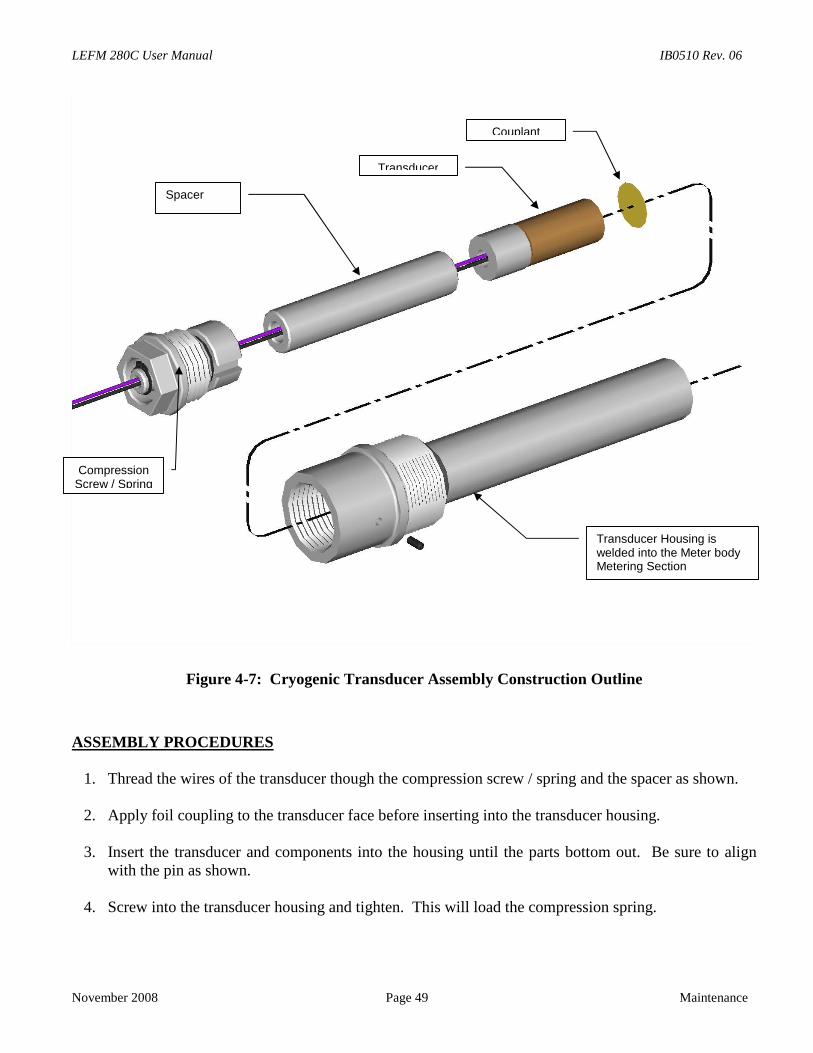
LEFM 280C User Manual IB0510 Rev. 06
November 2008 Page 49 Maintenance
Figure 4-7: Cryogenic Transducer Assembly Construction Outline
ASSEMBLY PROCEDURES
1. Thread the wires of the transducer though the compression screw / spring and the spacer as shown.
2. Apply foil coupling to the transducer face before inserting into the transducer housing.
3. Insert the transducer and components into the housing until the parts bottom out. Be sure to alignwith the pin as shown.
4. Screw into the transducer housing and tighten. This will load the compression spring.
Spacer
Transducer
CompressionScrew / Spring
Transducer Housing iswelded into the Meter bodyMetering Section
Couplant
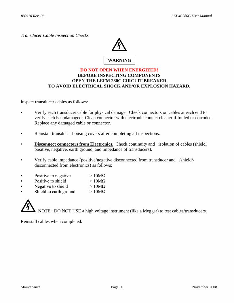
IB0510 Rev. 06 LEFM 280C User Manual
Maintenance Page 50 November 2008
Transducer Cable Inspection Checks
DO NOT OPEN WHEN ENERGIZED!BEFORE INSPECTING COMPONENTS
OPEN THE LEFM 280C CIRCUIT BREAKERTO AVOID ELECTRICAL SHOCK AND/OR EXPLOSION HAZARD.
Inspect transducer cables as follows:
• Verify each transducer cable for physical damage. Check connectors on cables at each end toverify each is undamaged. Clean connector with electronic contact cleaner if fouled or corroded.Replace any damaged cable or connector.
• Reinstall transducer housing covers after completing all inspections.
• Disconnect connectors from Electronics. Check continuity and isolation of cables (shield,positive, negative, earth ground, and impedance of transducers).
• Verify cable impedance (positive/negative disconnected from transducer and +/shield/-disconnected from electronics) as follows:
• Positive to negative > 10MΩ • Positive to shield > 10MΩ • Negative to shield > 10MΩ • Shield to earth ground > 10MΩ
NOTE: DO NOT USE a high voltage instrument (like a Meggar) to test cables/transducers.
Reinstall cables when completed.
WARNING
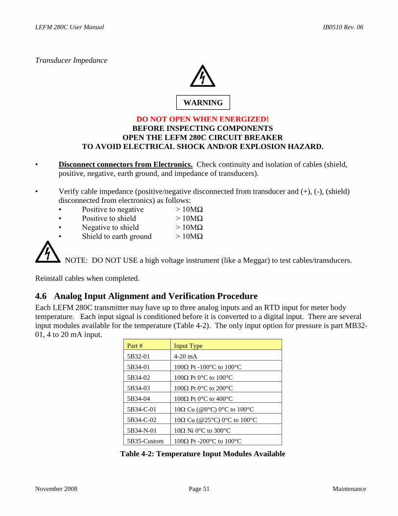
LEFM 280C User Manual IB0510 Rev. 06
November 2008 Page 51 Maintenance
Transducer Impedance
DO NOT OPEN WHEN ENERGIZED!BEFORE INSPECTING COMPONENTS
OPEN THE LEFM 280C CIRCUIT BREAKERTO AVOID ELECTRICAL SHOCK AND/OR EXPLOSION HAZARD.
• Disconnect connectors from Electronics. Check continuity and isolation of cables (shield,positive, negative, earth ground, and impedance of transducers).
• Verify cable impedance (positive/negative disconnected from transducer and (+), (-), (shield)disconnected from electronics) as follows:
• Positive to negative > 10MΩ • Positive to shield > 10MΩ • Negative to shield > 10MΩ • Shield to earth ground > 10MΩ
NOTE: DO NOT USE a high voltage instrument (like a Meggar) to test cables/transducers.
Reinstall cables when completed.
4.6 Analog Input Alignment and Verification ProcedureEach LEFM 280C transmitter may have up to three analog inputs and an RTD input for meter bodytemperature. Each input signal is conditioned before it is converted to a digital input. There are severalinput modules available for the temperature (Table 4-2). The only input option for pressure is part MB32-01, 4 to 20 mA input.
Part # Input Type
5B32-01 4-20 mA
5B34-01 100 Pt -100°C to 100°C
5B34-02 100 Pt 0°C to 100°C
5B34-03 100 Pt 0°C to 200°C
5B34-04 100 Pt 0°C to 400°C
5B34-C-01 10 Cu (@0°C) 0°C to 100°C
5B34-C-02 10 Cu (@25°C) 0°C to 100°C
5B34-N-01 10 Ni 0°C to 300°C
5B35-Custom 100 Pt -200°C to 100°C
Table 4-2: Temperature Input Modules Available
WARNING
IB0510 Rev. 06 LEFM 280C User Manual
Maintenance Page 52 November 2008
The inputs are scaled to linearly convert either (4-20mA) or (RTD inputs) between the maximum andminimum ranges. Adjustments to the analog input ranges can only be changed through the softwareinterface (See the LEFMLink manual for instruction on configuring this range).
Failed inputs will typically go to their lowest range. For example, a 4-20 mA pressure input scaled to 0-1000 psig will go to 0 psig if the input is removed. However, if the LEFM 280C does not respond tocalibrated inputs, then the following should be checked:
• Connection to the backplane (see Section 1)• Analog Input Interface Module
Meter Body Temperature (Location M1) Pressure (Location M2) Fluid Temperature (Location M3) Density (Location M4)
4.7 Analog Output VerificationWhen provided, each LEFM 280C transmitter may have up to four Analog Output Channels. Each analogchannel has a 0-20 mA (Part MB39-03), or 4-20 mA (part MB39-01) range, depending on the isolationmodule requested. The pulse output has a range of 0-5V. There are no adjustments to be performed forthe analog or pulse outputs. Analog outputs M5 – M8 can be mapped to any ModBus input register formaximum flexibility. By default the analog outputs are mapped as follows:
M5 FlowM6 Velocity of SoundM7 TemperatureM8 DensityM9 Pulse Output
4.7.1 Analog Scaling
The analog outputs are scaled linearly anywhere between their maximum and minimum values. Use theforce outputs function of LEFMLink to test the scaling of the analog outputs with input site devices (Seethe LEFMLink Manual).
4.7.2 Pulse Verification Tests
Similar to calibrating the Analog Outputs, a fixed frequency may be forced out of the transmitter pulseoutput. The ModBus Register for Frequency Output (Reference ModBus Manual) may be set to anyfrequency. Writing a value to this register and commanding the transmitter to use it, will force the pulseoutput to a fixed frequency. Returning the Frequency Output Register to 0 or normal, will return thetransmitter to normal operation. Alternatively, the LEFMLink program can be used.
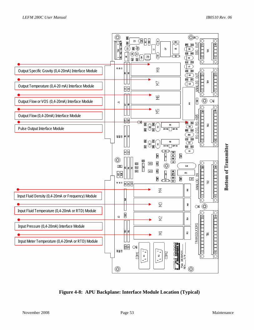
LEFM 280C User Manual IB0510 Rev. 06
November 2008 Page 53 Maintenance
Figure 4-8: APU Backplane: Interface Module Location (Typical)
Output Specific Gravity (0,4-20mA) Interface Module
Output Temperature (0,4-20 mA) Interface Module
Output Flow or VOS (0,4-20mA) Interface Module
Output Flow (0,4-20mA) Interface Module
Input Pressure (0,4-20mA) Interface Module
Input Meter Temperature (0,4-20mA or RTD) Module
Pulse Output Interface Module
Input Fluid Temperature (0,4-20mA or RTD) Module
Input Fluid Density (0,4-20mA or Frequency) Module

IB0510 Rev. 06 LEFM 280C User Manual
Maintenance Page 54 November 2008
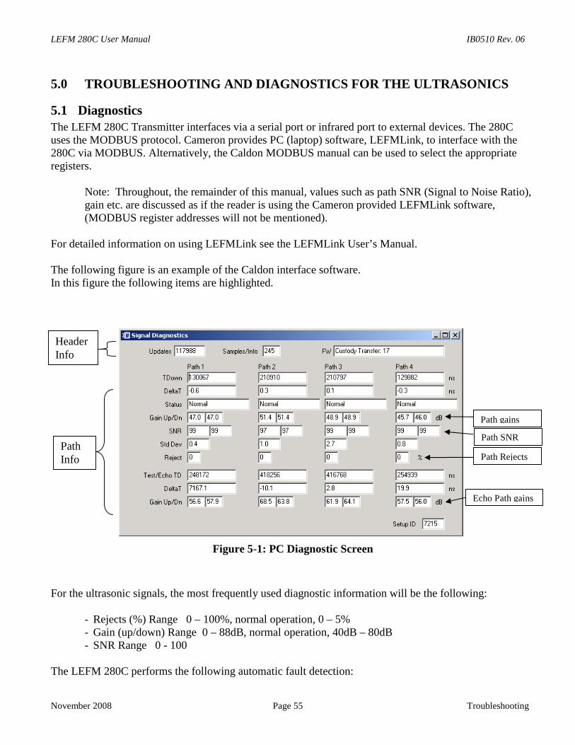
LEFM 280C User Manual IB0510 Rev. 06
November 2008 Page 55 Tr
5.0 TROUBLESHOOTING AND DIAGNOSTICS FOR THE ULTRASONICS
5.1 DiagnosticsThe LEFM 280C Transmitter interfaces via a serial port or infrared port to external devices. The 280Cuses the MODBUS protocol. Cameron provides PC (laptop) software, LEFMLink, to interface with the280C via MODBUS. Alternatively, the Caldon MODBUS manual can be used to select the appropriateregisters.
Note: Throughout, the remainder of this manual, values such as path SNR (Signal to Noise Ratio),gain etc. are discussed as if the reader is using the Cameron provided LEFMLink software,(MODBUS register addresses will not be mentioned).
For detailed information on using LEFMLink see the LEFMLink User’s Manual.
The following figure is an example of the Caldon interface software.In this figure the following items are highlighted.
Figure 5-1: PC Diagnostic Screen
For the ultrasonic signals, the most frequently used diagnostic information will be the followin
- Rejects (%) Range 0 – 100%, normal operation, 0 – 5%- Gain (up/down) Range 0 – 88dB, normal operation, 40dB – 80dB- SNR Range 0 - 100
The LEFM 280C performs the following automatic fault detection:
Path gains
Path SNR
E
PathInfo
HeaderInfo
Path Rejects
oubleshooting
g:
cho Path gains
IB0510 Rev. 06 LEFM 280C User Manual
Troubleshooting Page 56 November 2008
• The APU checks data quality of the ultrasonic signals and evaluates data against pre-setthresholds. The data is evaluated based on SNR (signal to noise ratio), cross-correlation tests andsignal statistics.
• Occasionally data will be rejected; however, this will not influence the operation. If an ultrasonicpath continues to reject data, the meter will alert the operator with an "ALARM" status and anerror code.
• The APU will output the current status through a digital output and MODBUS.
The meter status includes:
• "NORMAL" status (status bit on Terminal Block, TB5-5, is at 5 volts)
• "ALARM" status - 1, 2, or 3 paths failed - flow computed with a lower accuracy (status bit onTB5-5 is at 0 volts)
• "ALARM" status - all paths failed - flow is set to zero (0) – (status bit same as normal status)
The individual path status codes are:
• 0 - Path operating normally
• 1 - Path rejecting data due to low SNR, irregular statistics, or failing the correlation test.
• 6 - Path sound velocities are inconsistent with thresholds (typically up to 1% spread betweenpaths is acceptable).
• 7 - Path velocity fails profile test
• 8 - Path velocity inconsistent at low flows
• 10 - Path fails impedance self test
• 11 - Electronics fails clock accuracy test
NOTE: Caldon interface software interprets these codes and displays a text message.
LEFM 280C User Manual IB0510 Rev. 06
November 2008 Page 57 Troubleshooting
5.2 Path Troubleshooting
The LEFM 280C System continuously checks the data quality of each acoustic path. Each time the signalis sampled, the APU tests the signal as follows:
• Verifies path’s signal to noise ratio (SNR) is higher than its threshold value.
• Correlates the Upstream Signal with the Downstream Signal to test for “cycle skipping”. TheAPU rejects data that does not pass this correlation test.
• Verifies the statistics of the computed transit time and Delta T are acceptable.
5.2.1 Path Reject Status
When the path status indicates that the Reject Test failed, it indicates that the percentage of data that hasbeen rejected has exceeded the LEFM 280C System thresholds. The following troubleshooting sequencecan be followed to pinpoint the root cause.
Step 1) Verify that the meter body is full of liquid. For example, if the top path is failing, then thepipe may not be filled.
Step 2) Verify continuity for all cables.
Step 3) Check all APU power supply voltages.
If the LED for any power supply is not lit on the front of the APU card, then the fuse maybe blown, or the power supply has failed. (See Section 4.3).
Step 4) Check Transmit LED on APU board.
If transmit pulse on the APU is not lit, then the APU may need a configuration file,otherwise replace current APU board with a new APU board. (See Section 5.3)
Step 5) Check the Acoustic Signal
Check path gains (via MODBUS or Caldon Interface Software). If the path gains arehigh (85db and higher), then the signals may be too weak to operate. Weak signals can becaused by any of the following (listed from most likely to least likely)
Line is not full of liquid.
Line pressure is too low for the vapor pressure
Cable/wire from the meter to the transmitter is damaged
IB0510 Rev. 06 LEFM 280C User Manual
Troubleshooting Page 58 November 2008
Transducer coupling needs to be replaced (with grease couplants only)
Transducer has failed
Step 6) Look for shorted wires. The LEFM280C has a diagnostic feature that tests the impedanceof each transducer and cable. Review each transducer’s impedance (See LEFMLink orModBus Manual). Check out cables if any impedance measurement is less than 100 kΩ.
Step 7) Determine Which Transducer Has Failed
Except for the earliest versions of the products, the LEFM 280C has a diagnostic feature fordetermining which transducer(s), if any, needs attention. The transmitter continuously testseach transducer individually in a pulse–echo mode. Pulse-echo means that a transducertransmits acoustic energy across the liquid, echoes the energy off the opposing transducer,and then receives the energy it has sent. In pulse-echo mode, the transmitter then computesthe gain for both upstream and downstream transducers. Normally, the gains for theupstream and the downstream pulse-echo tests are equal. However, if there is a failedtransducer due to wiring, coupling, etc., then one transducer will have a higher gain. Usingthe regular acoustic paths and the diagnostic pulse-echo paths, follow these steps todetermine which transducer to evaluate:
1) Review the SNR (Signal to Noise Ratio) for each path (paths 1 through 8). The SNRshould be greater than 40 (or greater than 20 for high viscosities).
2) Review the gains for each acoustic path (both upstream and downstream). The gainsshould be between 40dB and 80dB. Upstream and downstream gain shouldnominally be within 3 dB of each other.
3) Review the percent rejected data for each path. The percent should be between 0and 5%.
4) Review the gains for each pulse-echo path (both upstream and downstream). Thepath with the higher gain should be investigated first.
Note: There will be situations where the pulse-echo paths are both at their maximum(~88dB). If this is the case, investigate the cables and the transducers of both transducers.
Remember the following troubleshooting tips:
• If all paths are in fail, not just one, then either the meter has no liquid or an electronicshardware failure has occurred.
• If a path has 100 % rejects it means the APU cannot lock onto a signal. It is possibly acable or transducer problem. (Note: When rejects equal 100% then the APU will alwaysindicate SNR=0 for the path).
LEFM 280C User Manual IB0510 Rev. 06
November 2008 Page 59 Troubleshooting
If an acoustic signal does not exist, or if SNR has degraded from installation, then follow checklistbelow:
• Verify the pipe is full of liquid.
• Check the transducer impedance. If the transducer impedance is less than 10 Megohms,then replace transducer.
NOTE: DO NOT USE a high voltage instrument (like a Meggar) to test cables/transducers.
• Check the impedance of the transducer cable. If cable impedance is less than 10Megohms, then replace/repair cable.
• Check continuity of transducer cable. If transducer cable continuity impedance isinfinite, then repair/replace cable.
• If a signal is present, the ultrasonic transducer may need to be reseated, or the acousticcoupling may need to be replaced. See Section 4.5.
5.3 Reprogramming the Transmitter
While it is not likely, there may be a time that the transmitter may need to be reprogrammed. This wouldtypically occur when an:
APU Board has been replaced with an inventory item, not specifically assigned to a given meter body.It is Camerons’s policy to provide a configuration file for each spool. This configuration file includes:
o Pipe Sizeo Pipe Transducer Frequencyo Acoustic Path Lengthso Calibration Constanto Alarm Settingso K-Factoro Analog Input/Output Scaling
Cameron maintains records and configuration files for all of its delivered meters. The simplest way toreprogram a transmitter is to use Caldon’s PC or Pocket PC interface software. The procedure is asfollows:
1) Select appropriate ModBus ID and Baud Rate (See Section 5.3.1)2) Select the configuration file for the meter body3) Send the Configuration File
Once these steps are complete, the transmitter is reprogrammed.

IB0510 Rev. 06 LEFM 280C User Manual
Troubleshooting Page 60 November 2008
The transmitter may also be reprogrammed through ModBus using the site interface, however, it is notrecommended to do the reprogramming this way. Given that there are many registers to load, the processwill be tedious and prone to errors.
5.3.1 ModBus ID and Baud Rate
All Caldon transmitters are programmed with ModBus ID set to 1, Baud Rate at 9600 and in RTU SlaveMode. If the transmitter has been reprogrammed with a different setting and this setting is not known,simply set DIP Switch Number 2 to up (TRUE) and toggle the reset switch (see Figure 5-2). Resetting thetransmitter in this mode forces the transmitter to operate with its default settings. In this mode thetransmitter will wait for a new setup before restarting:
NOTES:1. MAKE SURE YOU HAVE THE CORRECT SETUP FILE FIRST!2. MAKE SURE YOU PUSH DOWN DIP SWITCH NUMBER 2 WHEN FINISHED!
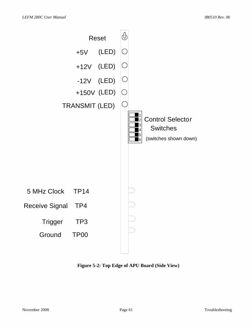
LEFM 280C User Manual IB0510 Rev. 06
November 2008 Page 61 Troubleshooting
Figure 5-2: Top Edge of APU Board (Side View)
Trigger TP3
Ground TP00
Receive Signal TP4
5 MHz Clock TP14
+150V (LED)
-12V (LED)
+5V (LED)
+12V (LED)
Reset
Control Selector
Switches
1
2
3
4
5
6
TRANSMIT (LED)
(switches shown down)

IB0510 Rev. 06 LEFM 280C User Manual
Troubleshooting Page 62 November 2008
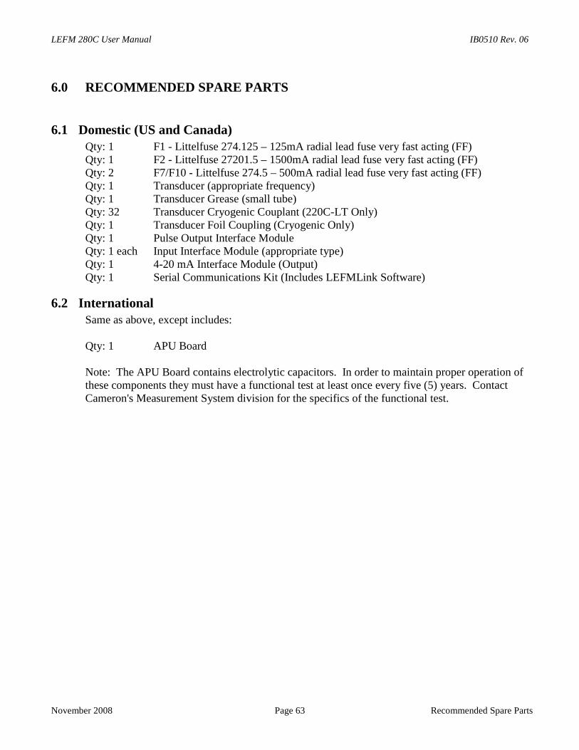
LEFM 280C User Manual IB0510 Rev. 06
November 2008 Page 63 Recommended Spare Parts
6.0 RECOMMENDED SPARE PARTS
6.1 Domestic (US and Canada)Qty: 1 F1 - Littelfuse 274.125 – 125mA radial lead fuse very fast acting (FF)Qty: 1 F2 - Littelfuse 27201.5 – 1500mA radial lead fuse very fast acting (FF)Qty: 2 F7/F10 - Littelfuse 274.5 – 500mA radial lead fuse very fast acting (FF)Qty: 1 Transducer (appropriate frequency)Qty: 1 Transducer Grease (small tube)Qty: 32 Transducer Cryogenic Couplant (220C-LT Only)Qty: 1 Transducer Foil Coupling (Cryogenic Only)Qty: 1 Pulse Output Interface ModuleQty: 1 each Input Interface Module (appropriate type)Qty: 1 4-20 mA Interface Module (Output)Qty: 1 Serial Communications Kit (Includes LEFMLink Software)
6.2 InternationalSame as above, except includes:
Qty: 1 APU Board
Note: The APU Board contains electrolytic capacitors. In order to maintain proper operation ofthese components they must have a functional test at least once every five (5) years. ContactCameron's Measurement System division for the specifics of the functional test.

IB0510 Rev. 06 LEFM 280C User Manual
Recommended Spare Parts Page 64 November 2008
LEFM 280C User Manual IB0510 Rev. 06
November 2008 Page 65 Appendix A
7.0 Appendix A
7.1 ATEX CERTIFICATIONS (Document IB0613)
See the following ATEX certifications for conditions of safe use for the meter manifold and thetransmitter. The temperature ranges listed are for the enclosures indicated on the certificate. Thetemperature limit of the meter assembly is dependent on the temperature limits for the components used toconnect the meter to the electronics and may limit the temperature limits for the assembled meter. See themeter nameplate for the temperature limit of the system as assembled.

IB0510 Rev. 06 LEFM 280C User Manual
Appendix A Page 66 November 2008
WARRANTY - LIMITATION OF LIABILITY: Seller warrants only title to theproducts, software, supplies and materials and that, except as to software, thesame are free from defects in workmanship and materials for a period of one (1)year from the date of delivery. Seller does not warranty that software is free fromerror or that software will run in an uninterrupted fashion. Seller provides allsoftware "as is". THERE ARE NO WARRANTIES, EXPRESS OR IMPLIED, OFMERCHANTABILITY, FITNESS OR OTHERWISE WHICH EXTEND BEYONDTHOSE STATED IN THE IMMEDIATELY PRECEDING SENTENCE. Seller'sliability and Buyer's exclusive remedy in any case of action (whether in contract,tort, breach of warranty or otherwise) arising out of the sale or use of anyproducts, software, supplies, or materials is expressly limited to the replacementof such products, software, supplies, or materials on their return to Seller or, atSeller's option, to the allowance to the customer of credit for the cost of suchitems. In no event shall Seller be liable for special, incidental, indirect, punitive orconsequential damages. Seller does not warrant in any way products, software,supplies and materials not manufactured by Seller, and such will be sold onlywith the warranties that are given by the manufacturer thereof. Seller will passonly through to its purchaser of such items the warranty granted to it by themanufacturer.

CaldonUltrasonics
Customer Service & Technical Support
1000 McClaren Woods DriveCoraopolis, PA 15108 USATel 724-273-9300
The ultrasonic measurementgroup of Cameron
www.c-a-m.com


![Nonlinear UT for NDT [Kompatibilitetsläge] · Nonlinear ultrasonics for NDTNonlinear ultrasonics for NDT Linear Ultrasonics: Detection of Flaws/Discontinuities • Detect geometric](https://img.pdfslide.us/doc/110x75/5eb54bd032d9642d8e2c4d0a/nonlinear-ut-for-ndt-kompatibilitetslge-nonlinear-ultrasonics-for-ndtnonlinear.jpg)