Embed Size (px)
Citation preview
Ultrasonic Testing
Part 3

The Phenomenon of Sound
REFLECTIONREFRACTION
DIFFRACTION

Law of Reflection
• Angle of Incidence = Angle of Reflection
60o 60o

Inclined incidence(not at 90o )
Incident
Transmitted
The sound is refracted due to differences in
sound velocity in the 2 DIFFERENT materials

REFRACTION• Only occurs when:The incident angle is other than 0°
Water
Steel
Steel
Steel
Water
Steel
30°
Refracted

REFRACTION• Only occurs when:The incident angle is other than 0°
Steel
Steel
Water
Steel
30°
Refracted
The Two Materials has different
VELOCITIES
No Refraction
30°
30°
65°

Snell’s Law
I
R
Material 1
Material 2
2 Materialin
1 Material
Vel
inVel
RSine
ISine
Incident
Refracted
Normal

Snell’s Law
Perspex
Steel
S
CC
CC
S
When an incident beam of sound
approaches an interface of two
different materials:
REFRACTION occurs
There may be more than one waveform
transmitted into the second material,
example: Compression and Shear
When a waveform changes
into another waveform:
MODE CHANGE

Snell’s Law
Perspex
Steel
C
CS
If the angle of Incident is
increased the angle of
refraction also increases
Up to a point where the
Compression Wave is at
90° from the Normal
90° This happens at the
FIRST CRITICAL ANGLE
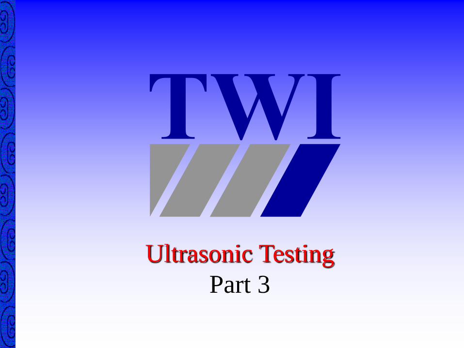
1st Critical Angle
C
27.4
S
33
C Compression wave refracted
at 90 degrees

1st Critical Angle Calculation
C
Perspex
SteelC
5960
2730
90
I
Sine
Sine
5960
2730SinI
458.0SinI
26.27I
S
190Sin
27.2
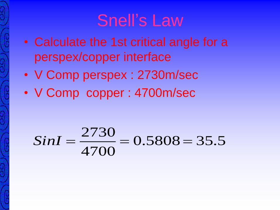
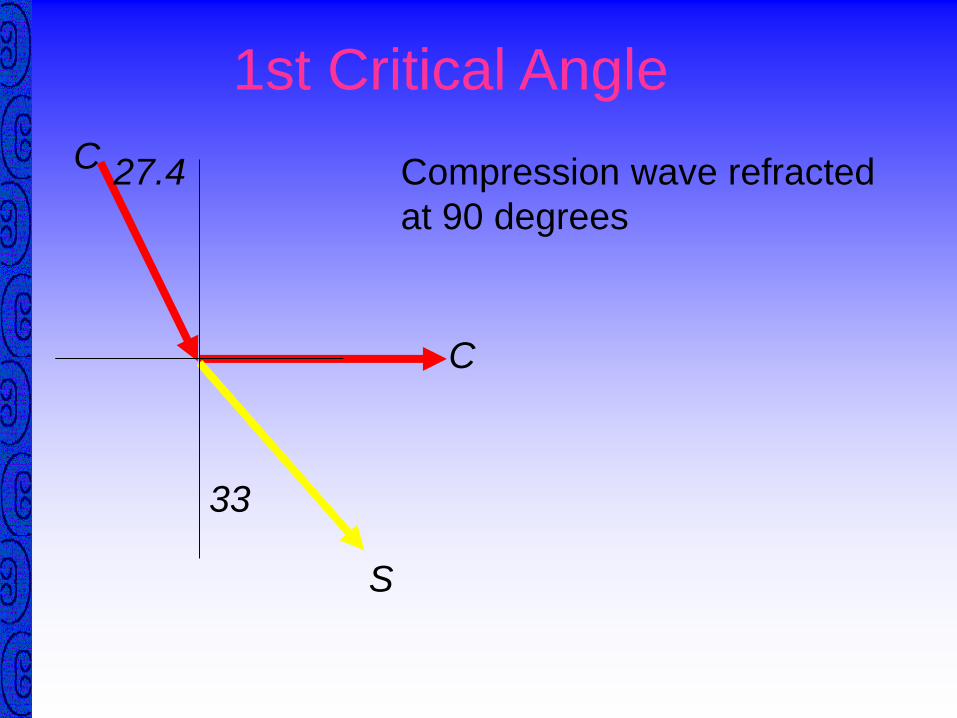
Snell’s Law• Calculate the 1st critical angle for a
perspex/copper interface
• V Comp perspex : 2730m/sec
• V Comp copper : 4700m/sec
5.355808.04700
2730SinI

2nd Critical Angle
C
S (Surface Wave)
90
C
Shear wave refracted at 90 degrees
57
Shear wave becomes a surface wave

2nd Critical Angle Calculation
C
Perspex
Steel
C
3240
2730
90
I
Sine
Sine
3240
2730SinI
8425.0SinI
4.57I
S190Sin
57.4

Snell’s Law
C
Perspex
Steel
C
20
48.3
2 Materialin
1 Material
Vel
inVel
RSine
ISine
5960
2730
48.3
20
Sine
Sine
4580.04580.0
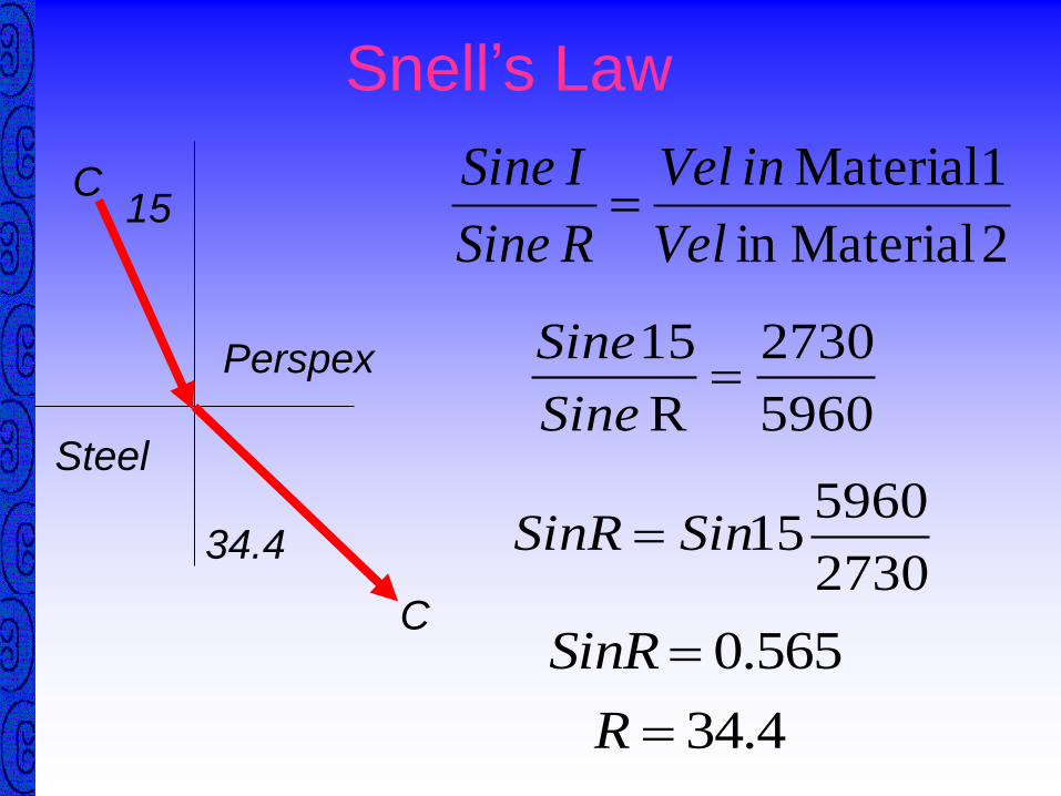
Snell’s Law
C
Perspex
Steel
C
15
34.4
2 Materialin
1 Material
Vel
inVel
RSine
ISine
5960
2730
R
15
Sine
Sine
2730
596015SinSinR
565.0SinR
4.34R

Snell’s LawC
Perspex
Steel
C
20
S
48.3
24
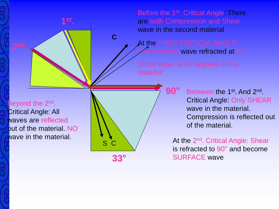
1st.
2nd.
33°
90°
Before the 1st. Critical Angle: There
are both Compression and Shear
wave in the second material
S C
At the FIRST CRITICAL ANGLE
Compression wave refracted at 90°
Shear wave at 33 degrees in the
material
Between the 1st. And 2nd.
Critical Angle: Only SHEAR
wave in the material.
Compression is reflected out
of the material.
C
At the 2nd. Critical Angle: Shear
is refracted to 90° and become
SURFACE wave
Beyond the 2nd.
Critical Angle: All
waves are reflected
out of the material. NO
wave in the material.

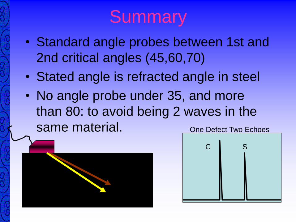
Summary
• Standard angle probes between 1st and
2nd critical angles (45,60,70)
• Stated angle is refracted angle in steel
• No angle probe under 35, and more
than 80: to avoid being 2 waves in the
same material.
C
S
C S
One Defect Two Echoes
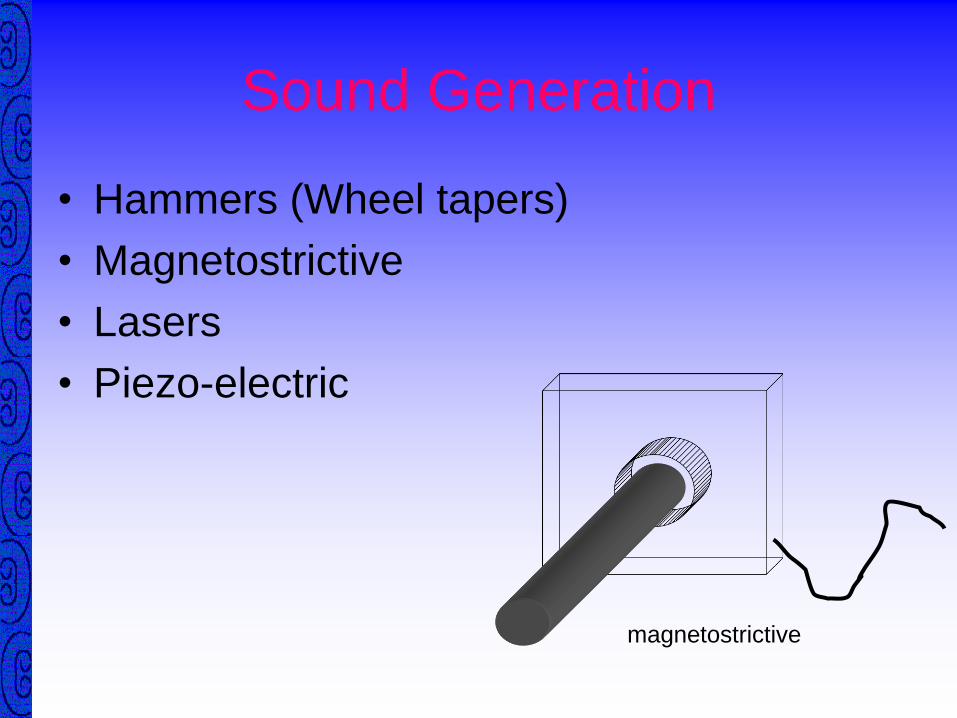
Sound Generation
• Hammers (Wheel tapers)
• Magnetostrictive
• Lasers
• Piezo-electric
magnetostrictive

Piezo-Electric Effect• When exposed to an alternating current a
crystal expands and contracts
• Converting electrical energy into mechanical
- + + - - +

Piezo-Electric Materials
QUARTZ
• Resistant to wear
• Insoluble in water
• Resists ageing
• Inefficient converter of
energy
• Needs a relatively high
voltageVery rarely used nowadays
LITHIUM SULPHATE
• Efficient receiver
• Low electrical
impedance
• Operates on low
voltage
• Water soluble
• Low mechanical
strength
• Useable only up to 30ºCUsed mainly in medical

Polarized Crystals
• Powders heated to
high temperatures
• Pressed into shape
• Cooled in very
strong electrical
fields
Examples
• Barium titanate (Ba Ti O3)
• Lead metaniobate
(Pb Nb O6)
• Lead zirconate titanate
(Pb Ti O3 or Pb Zr O3)
Most of the probes for conventional usage use
PZT : Lead Zirconate Titanate

Probes
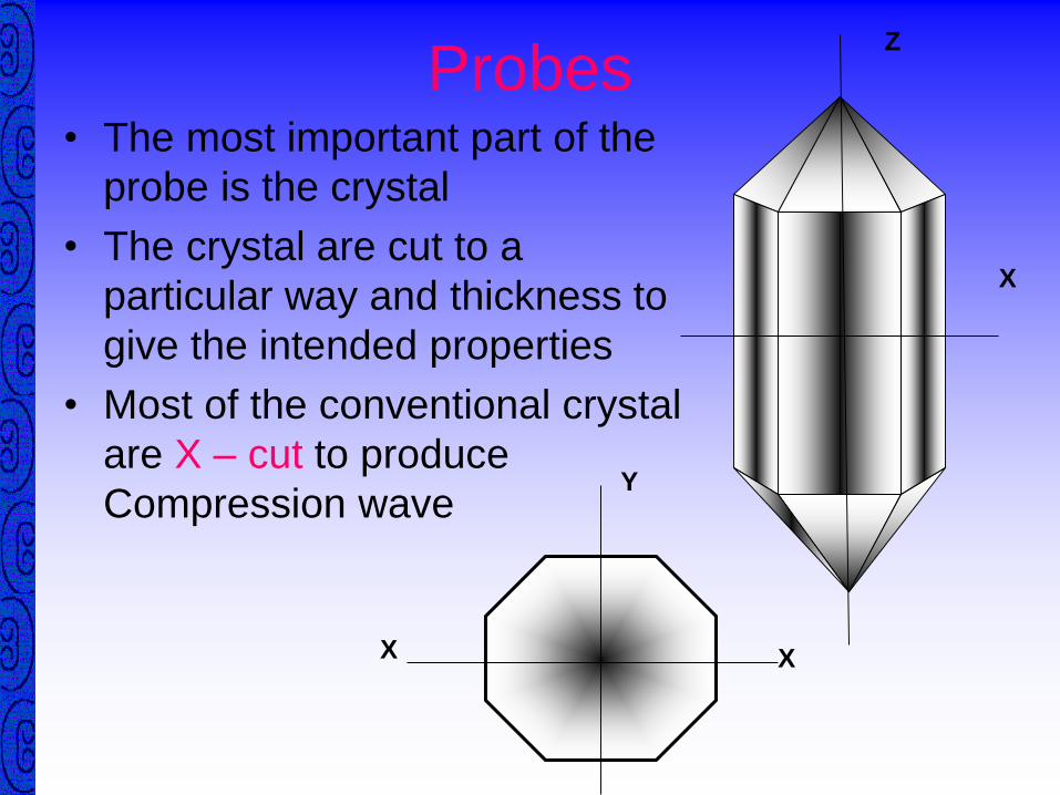
Probes• The most important part of the
probe is the crystal
• The crystal are cut to a
particular way and thickness to
give the intended properties
• Most of the conventional crystal
are X – cut to produce
Compression wave
Z
X
X X
Y

Probes
• The frequency of the probe depends on
the THICKNESS of the crystal
• Formula for frequency:
Ff = V / 2t
Where Ff = the Fundamental frequency
V = the velocity in the crystal
t = the thickness of the crystal
Fundamental frequency is the frequency of the material ( crystal )
where at that frequency the material will vibrate.

Probes
• The Thinner the crystal the Higher the frequency
• Which of the followings has the Thinnest crystal ?
1 MHz Compression probe
5 MHz Compression probe
10 MHz Shear probe
25 MHz Shear probe
25 MHz Shear
Probe

Probe Design
• Compression Probe
– Normal probe
– 0°
Damping
Transducer
Electrical
connectors
Housing

Probe Design
• Shear Probe
– Angle probe
DampingTransducer
Perspex wedge
Backing
medium
Probe
Shoe

Probe Design
Twin Crystal
Advantages
• Can be focused
• Measure thin plate
• Near surface
resolution
Disadvantages
• Difficult to use on
curved surfaces
• Sizing small defects
• Signal amplitude /
focal spot length
Transmitter Receiver
Focusing
lensSeparator /
Insulator

Ultrasonic Displays
• A-Scan
• B-Scan End View
• C-Scan Plan View
• D-Scan Side View
• P-Scan or “projection scan” collects and
combines A, B, C & D Scan information

Ultrasonic Displays• A scan
The CRT (Cathode Ray Tube) display
The Horizontal axis :
Represents time base / beam path length / distance / depth
The Vertical axis :
Represent the amount of sound energy returned to the crystal

Ultrasonic Displays
• B scan
The End View Display
B

Ultrasonic Displays
• C scan
The Plan View Display
C
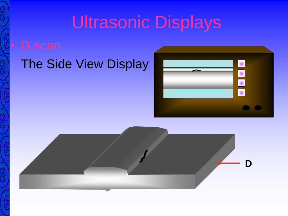
Ultrasonic Displays
• D scan
The Side View Display
D

Ultrasonic Test Methods
• Pulse Echo
• Through Transmission
• Transmission with Reflection (pulse echo techniques where the transmitter is
separate from the receiver - e.g. tandem testing, time
of flight)

Pulse Echo Technique
• Single probe sends
and receives sound
• Gives an indication of
defect depth and
dimensions

Defect OrientationONLY DEFECTS HAVING A SUITABLY ORIENTATED
REFLECTING SURFACE CAN BE DETECTED BY PULSE ECHO METHODS!!
Orientation favourable, sound reflected back to
point of origin
Orientation unfavourable, sound not reflected back
to point of origin

Through Transmission Testing• Transmitting and receiving probes on
opposite sides of the specimen
• Pulsed or Continuous sound
• Presence of defect indicated by
reduction in transmission signal
• No indication of defect location
• Easily automated
• Commonly integrated into plate rolling
mills - lamination testing

Through Transmission Technique
Transmitting and
receiving probes
on opposite sides
of the specimen
Tx Rx
Presence of defect
indicated by
reduction in
transmission signal
No indication of
defect location


Through Transmission Technique
Advantages
• Less attenuation
• No probe ringing
• No dead zone
• Orientation does not
matter
Disadvantages
• Defect not located
• Defect can’t be
identified
• Vertical defects
don’t show
• Must be automated
• Need access to both
surfaces

Transmission with ReflectionRT
Also known as:
Tandem Technique or
Pitch and Catch Technique

Transmission with
ReflectionT R
TANDEM TESTING

Transmission with Reflection
T R
TANDEM TESTING

Automated Inspections
• Pulse Echo
• Through Transmission
• Transmission with Reflection
• Contact scanning
• Gap scanning
• Immersion testing

Gap Scanning
• Probe held a fixed
distance above the
surface (1 or 2mm)
• Couplant is fed into
the gap

Immersion Testing
• Component is placed in a water filled tank
• Item is scanned with a probe at a fixed distance above the surface

Immersion Testing

Immersion Testing
Water
path
distance
Water path distance
Front surface Back surface
Defect