Embed Size (px)
Citation preview
Ultrasonic Steel Cleanliness Inspection (SEP 1927) ECNDT Moscow, June 2010
DIN EN ISO 9001:2000
Ultrasonic Steel Cleanliness Inspection ECNDT2010
KARL DEUTSCH Prüf- und Messgerätebau GmbH + Co KG Otto-Hausmann-Ring 101 D-42115 Wuppertal Tel. (+49 -202) 71 92 - 0 Fax (+49 -202) 71 49 32 e-mail: [email protected] Seite 1 von 1
Ultrasonic Steel Cleanliness Inspection
According to SEP 1927 Based on the ECHOGRAPH 1093
Dipl.-Ing. Mathias RAZENG, Dipl.-Phys. Klaus MAXAM,
Dr.(USA) Wolfram A. Karl DEUTSCH
KARL DEUTSCH Prüf- und Messgerätebau GmbH + Co KG, Wuppertal
[email protected], www.karldeutsch.de
Summary. Current methods for the examination of the steel cleanliness are the blue shortness test (macro purity grade in accordance with SEP 1584) and microscopy (micro purity grade in accordance with EN50602). Both methods provide information about the inspected surfaces but no volumetric information is obtained.
To overcome such drawbacks, it is proposed to apply an ultrasonic test in immersion technique in accordance with the SEP 1927 as a supplement or even alternate test. Important benefits of this volumetric test are a higher reproducibility and the possibility of establishing an automated testing procedure. The new test specification was published by the VDEh, the German Iron and Steel Institute. The KARL DEUTSCH company was an active member of the respective working group.
Introduction
The so-called cleanliness is a quality attribute of steel. The occurrence and distribution of non-metallic inclusions is determined. Such a measurement must be carried out for each steel batch because the steel properties depend on the respective melting process.
First, the existing testing methods are briefly described. For each batch (for instance 100 to) a few disk-shaped samples are tested with the blue shortness test. Each steel disk is fractured at blue brittleness temperature. At the applied temperature (approx. 300 - 600°C, depending on the alloy) a blue oxide layer occurs on the fracture interface. This explains the name of this procedure due to the intense colouring. The blue colour produces a good optical contrast to non-metallic inclusions. They are well visible if their size exceeds approx. 20 µm (depending on alloy and texture). Whether the fracture surface reveals inclusions which are located near that surface, depends on local the tensile strength conditions and on the distance between the respective inclusions and the fracture surface. The interpretation for this test is purely visual and it requires only a simple preparation of test specimens. The result is called “macro purity grade“.
Ultrasonic Steel Cleanliness Inspection (SEP 1927) ECNDT Moscow, June 2010
DIN EN ISO 9001:2000
Before using a microscope the specimens have to be excessively grinded and polished. Only inclusions directly within the polished surface become visible. This method is only advisable if many small inclusions occur which are fairly uniformly distributed within the volume. The result is called “micro purity grade”.
A new alternative method to gain information about the macro purity grade for a volume is described in the new test specification SEP 1927: Ultrasonic Immersion Testing Method for Determining the Macroscopic Cleanliness Rate of Rolled or Forged Steel Bars.
The corresponding working group of the VDEh (German Iron and Steel Institute, Duesseldorf) comprises steel making companies, steel end users and test equipment manufacturers. The aim of the project was to ensure the comparability of the test results from various testing systems. This is done by harmonization of the test procedure and by characterizing some of the components of the testing systems (e.g. the ultrasonic probes). In addition, a calibration block with artificial defects has been defined which can be used for periodical check-ups and for the regular sensitivity calibration of the systems.
Overview of the Ultrasonic Electronics
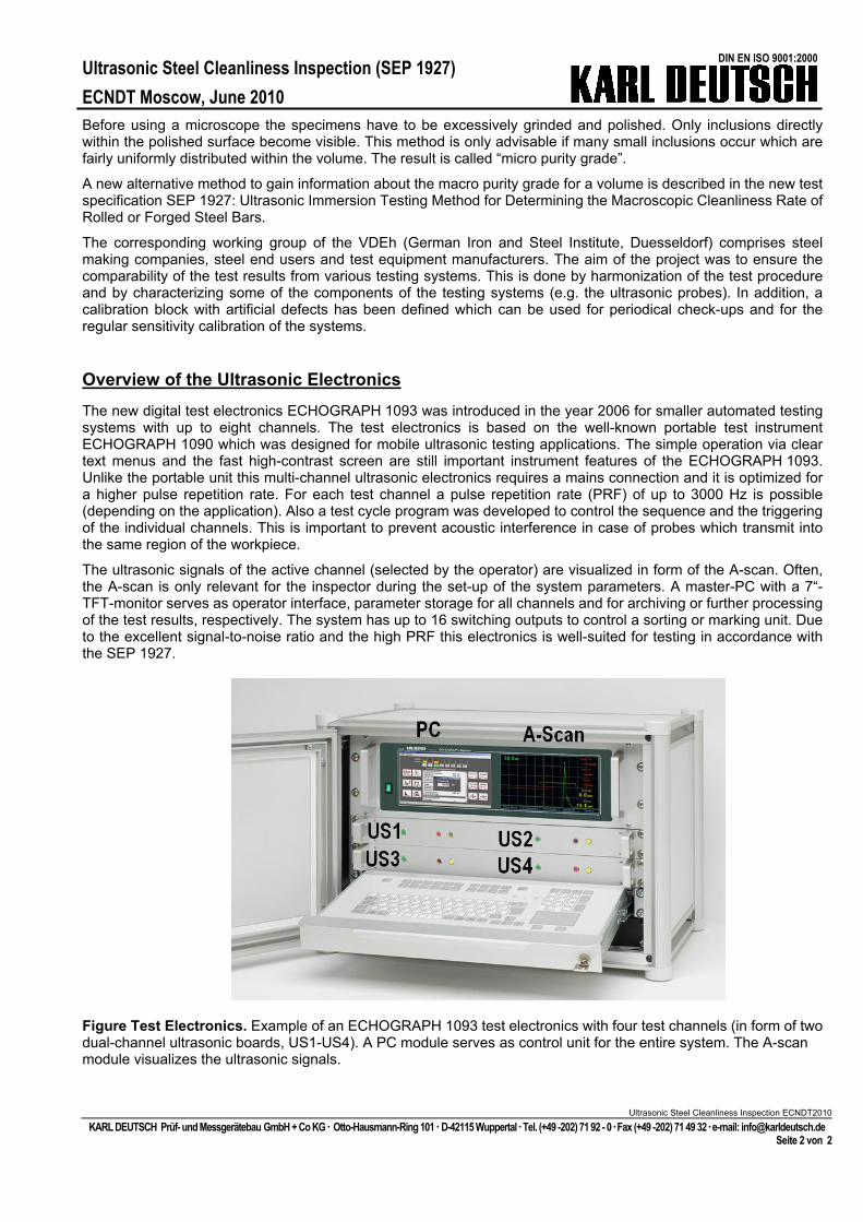
The new digital test electronics ECHOGRAPH 1093 was introduced in the year 2006 for smaller automated testing systems with up to eight channels. The test electronics is based on the well-known portable test instrument ECHOGRAPH 1090 which was designed for mobile ultrasonic testing applications. The simple operation via clear text menus and the fast high-contrast screen are still important instrument features of the ECHOGRAPH 1093. Unlike the portable unit this multi-channel ultrasonic electronics requires a mains connection and it is optimized for a higher pulse repetition rate. For each test channel a pulse repetition rate (PRF) of up to 3000 Hz is possible (depending on the application). Also a test cycle program was developed to control the sequence and the triggering of the individual channels. This is important to prevent acoustic interference in case of probes which transmit into the same region of the workpiece.
The ultrasonic signals of the active channel (selected by the operator) are visualized in form of the A-scan. Often, the A-scan is only relevant for the inspector during the set-up of the system parameters. A master-PC with a 7“-TFT-monitor serves as operator interface, parameter storage for all channels and for archiving or further processing of the test results, respectively. The system has up to 16 switching outputs to control a sorting or marking unit. Due to the excellent signal-to-noise ratio and the high PRF this electronics is well-suited for testing in accordance with the SEP 1927.
Figure Test Electronics. Example of an ECHOGRAPH 1093 test electronics with four test channels (in form of two dual-channel ultrasonic boards, US1-US4). A PC module serves as control unit for the entire system. The A-scan module visualizes the ultrasonic signals.
Ultrasonic Steel Cleanliness Inspection ECNDT2010
KARL DEUTSCH Prüf- und Messgerätebau GmbH + Co KG Otto-Hausmann-Ring 101 D-42115 Wuppertal Tel. (+49 -202) 71 92 - 0 Fax (+49 -202) 71 49 32 e-mail: [email protected] Seite 2 von 2
Ultrasonic Steel Cleanliness Inspection (SEP 1927) ECNDT Moscow, June 2010
DIN EN ISO 9001:2000
Ultrasonic Steel Cleanliness Inspection ECNDT2010
KARL DEUTSCH Prüf- und Messgerätebau GmbH + Co KG Otto-Hausmann-Ring 101 D-42115 Wuppertal Tel. (+49 -202) 71 92 - 0 Fax (+49 -202) 71 49 32 e-mail: [email protected] Seite 3 von 3
Overview of the ECHOGRAPH 1093 User Interface
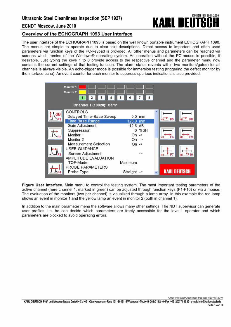
The user interface of the ECHOGRAPH 1093 is based on the well known portable instrument ECHOGRAPH 1090. The menus are simple to operate due to clear text descriptions. Direct access to important and often used parameters via function keys of the PC-keypad is provided. All other menus and parameters can be reached via screens which remind of the Windows® operating system. An operation without the PC-mouse is possible, if desirable. Just typing the keys 1 to 8 provide access to the respective channel and the parameter menu now contains the current settings of that testing function. The alarm status (events within two monitors/gates) for all channels is always visible. An echo-trigger mode is possible for immersion testing (triggering the defect monitor by the interface echo). An event counter for each monitor to suppress spurious indications is also provided.
Figure User Interface. Main menu to control the testing system. The most important testing parameters of the active channel (here channel 1, marked in green) can be adjusted through function keys (F1-F10) or via a mouse. The evaluation of the monitors (two per channel) is visualized through a lamp array. In this example the red lamp shows an event in monitor 1 and the yellow lamp an event in monitor 2 (both in channel 1).
In addition to the main parameter menu the software allows many other settings. The NDT supervisor can generate user profiles, i.e. he can decide which parameters are freely accessible for the level-1 operator and which parameters are blocked to avoid operating errors.
Ultrasonic Steel Cleanliness Inspection (SEP 1927) ECNDT Moscow, June 2010
DIN EN ISO 9001:2000
Ultrasonic Steel Cleanliness Inspection ECNDT2010
KARL DEUTSCH Prüf- und Messgerätebau GmbH + Co KG Otto-Hausmann-Ring 101 D-42115 Wuppertal Tel. (+49 -202) 71 92 - 0 Fax (+49 -202) 71 49 32 e-mail: [email protected] Seite 4 von 4
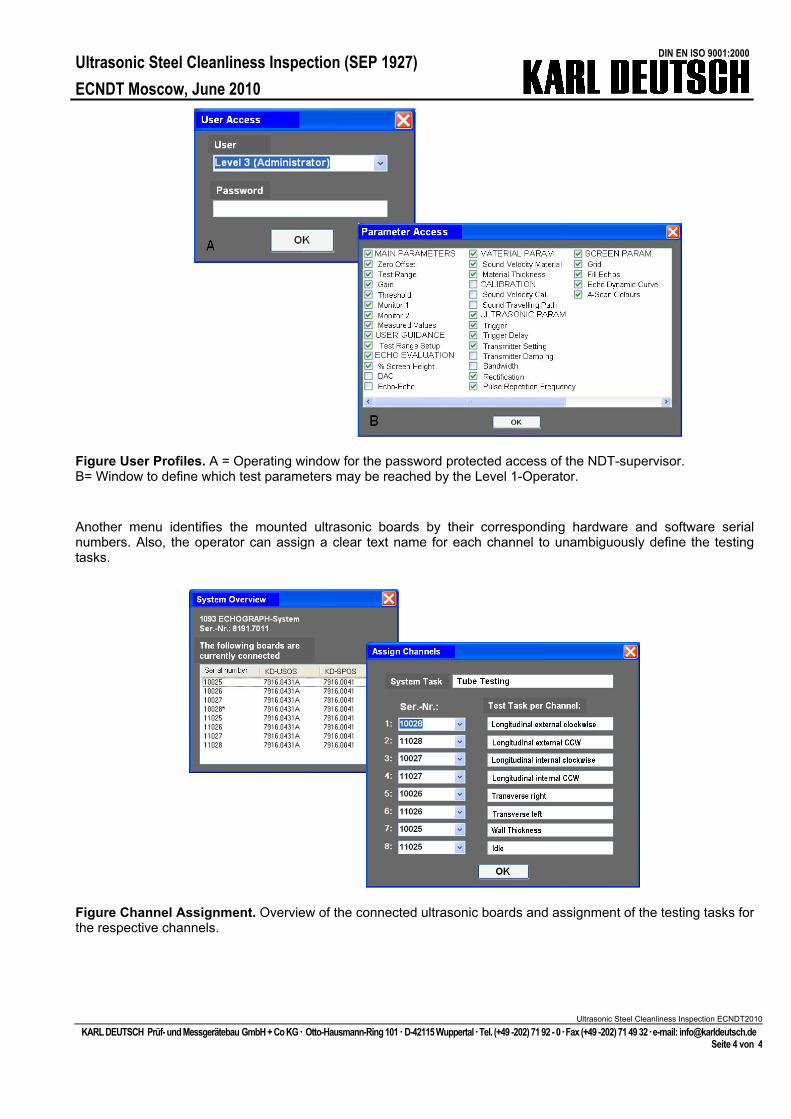
Figure User Profiles. A = Operating window for the password protected access of the NDT-supervisor. B= Window to define which test parameters may be reached by the Level 1-Operator.
Another menu identifies the mounted ultrasonic boards by their corresponding hardware and software serial numbers. Also, the operator can assign a clear text name for each channel to unambiguously define the testing tasks.
Figure Channel Assignment. Overview of the connected ultrasonic boards and assignment of the testing tasks for the respective channels.
Ultrasonic Steel Cleanliness Inspection (SEP 1927) ECNDT Moscow, June 2010
DIN EN ISO 9001:2000
Ultrasonic Steel Cleanliness Inspection ECNDT2010
KARL DEUTSCH Prüf- und Messgerätebau GmbH + Co KG Otto-Hausmann-Ring 101 D-42115 Wuppertal Tel. (+49 -202) 71 92 - 0 Fax (+49 -202) 71 49 32 e-mail: [email protected] Seite 5 von 5
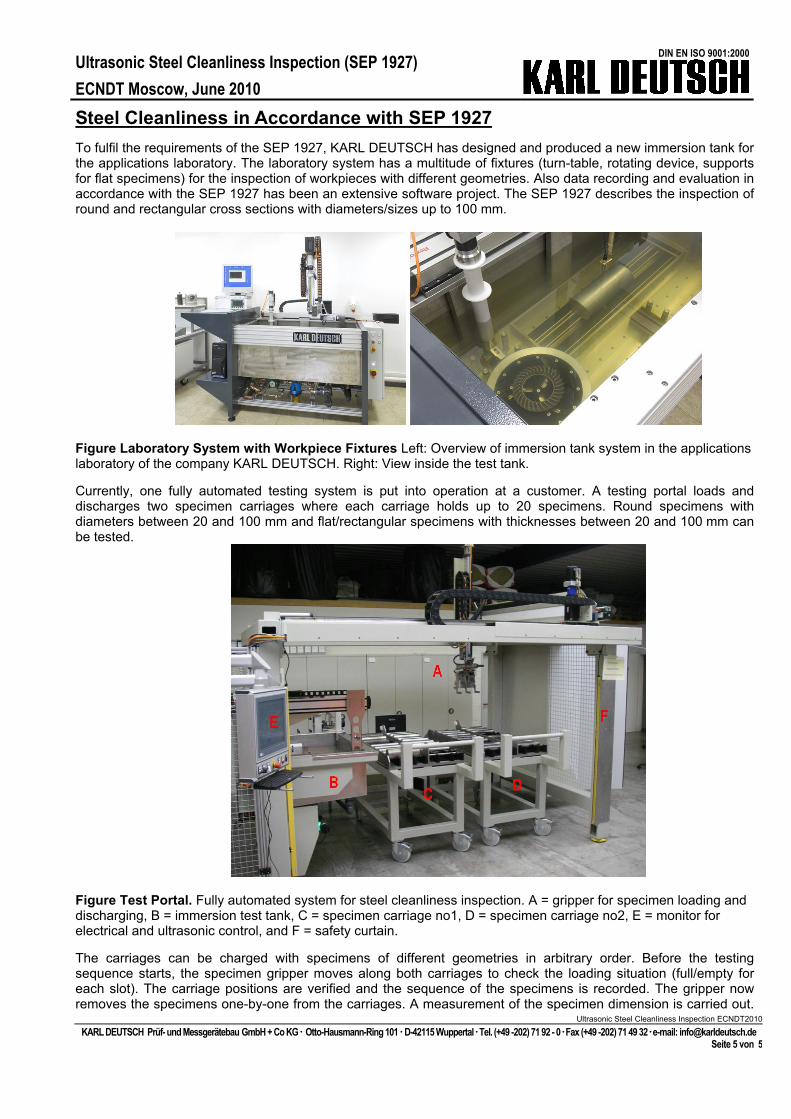
Steel Cleanliness in Accordance with SEP 1927 To fulfil the requirements of the SEP 1927, KARL DEUTSCH has designed and produced a new immersion tank for the applications laboratory. The laboratory system has a multitude of fixtures (turn-table, rotating device, supports for flat specimens) for the inspection of workpieces with different geometries. Also data recording and evaluation in accordance with the SEP 1927 has been an extensive software project. The SEP 1927 describes the inspection of round and rectangular cross sections with diameters/sizes up to 100 mm.
Figure Laboratory System with Workpiece Fixtures Left: Overview of immersion tank system in the applications laboratory of the company KARL DEUTSCH. Right: View inside the test tank.
Currently, one fully automated testing system is put into operation at a customer. A testing portal loads and discharges two specimen carriages where each carriage holds up to 20 specimens. Round specimens with diameters between 20 and 100 mm and flat/rectangular specimens with thicknesses between 20 and 100 mm can be tested.
Figure Test Portal. Fully automated system for steel cleanliness inspection. A = gripper for specimen loading and discharging, B = immersion test tank, C = specimen carriage no1, D = specimen carriage no2, E = monitor for electrical and ultrasonic control, and F = safety curtain.
The carriages can be charged with specimens of different geometries in arbitrary order. Before the testing sequence starts, the specimen gripper moves along both carriages to check the loading situation (full/empty for each slot). The carriage positions are verified and the sequence of the specimens is recorded. The gripper now removes the specimens one-by-one from the carriages. A measurement of the specimen dimension is carried out.
Ultrasonic Steel Cleanliness Inspection (SEP 1927) ECNDT Moscow, June 2010
DIN EN ISO 9001:2000
Ultrasonic Steel Cleanliness Inspection ECNDT2010
KARL DEUTSCH Prüf- und Messgerätebau GmbH + Co KG Otto-Hausmann-Ring 101 D-42115 Wuppertal Tel. (+49 -202) 71 92 - 0 Fax (+49 -202) 71 49 32 e-mail: [email protected] Seite 6 von 6
After storing this information within a higher-ranked data base the required ultrasonic parameters for each specimen are retrieved. The specimen is positioned into the corresponding workpiece fixture within the immersion tank and is finally tested. Flat and rectangular cross sections are tested in a x-y-motion while round cross sections are tested with a helical test trace. At the end of each test an automated evaluation in accordance with the SEP 1927 is carried out. The number of defects and their respective size are determined. The testing class and corresponding purity grade is then calculated. Finally, the test results are transferred to the host network for further treatment. After setting up the machine (mainly recording the DAC-curve for the sensitivity calibration), a fully automated operation without human interference for highest productivity is ensured.
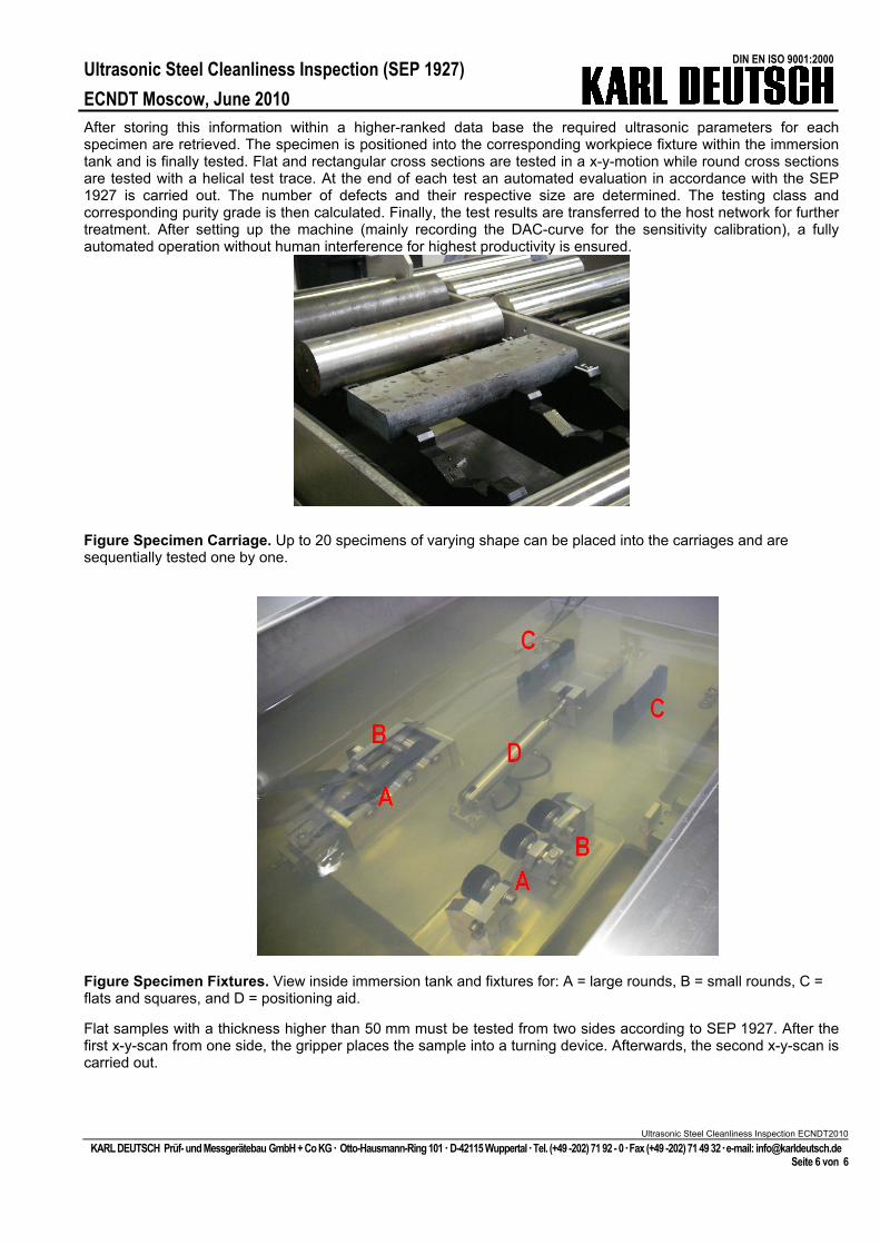
Figure Specimen Carriage. Up to 20 specimens of varying shape can be placed into the carriages and are sequentially tested one by one.
Figure Specimen Fixtures. View inside immersion tank and fixtures for: A = large rounds, B = small rounds, C = flats and squares, and D = positioning aid.
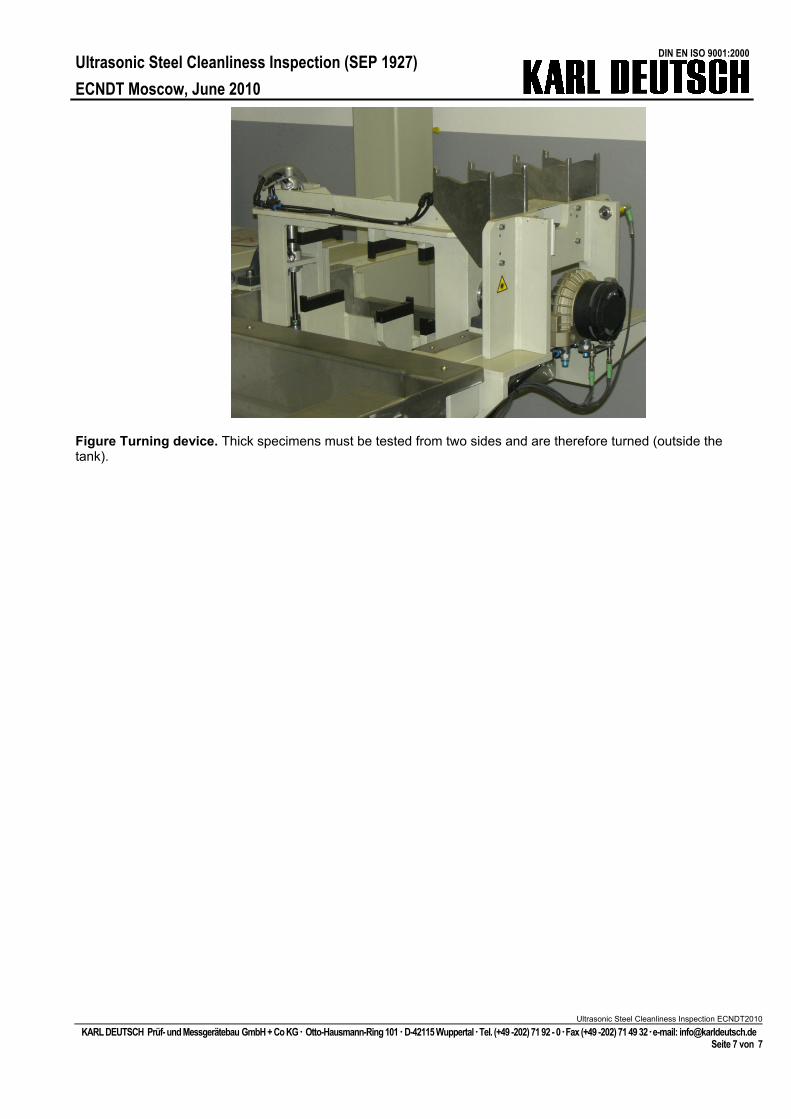
Flat samples with a thickness higher than 50 mm must be tested from two sides according to SEP 1927. After the first x-y-scan from one side, the gripper places the sample into a turning device. Afterwards, the second x-y-scan is carried out.
Ultrasonic Steel Cleanliness Inspection (SEP 1927) ECNDT Moscow, June 2010
DIN EN ISO 9001:2000
Ultrasonic Steel Cleanliness Inspection ECNDT2010
KARL DEUTSCH Prüf- und Messgerätebau GmbH + Co KG Otto-Hausmann-Ring 101 D-42115 Wuppertal Tel. (+49 -202) 71 92 - 0 Fax (+49 -202) 71 49 32 e-mail: [email protected] Seite 7 von 7
Figure Turning device. Thick specimens must be tested from two sides and are therefore turned (outside the tank).
Ultrasonic Steel Cleanliness Inspection (SEP 1927) ECNDT Moscow, June 2010
DIN EN ISO 9001:2000
Ultrasonic Steel Cleanliness Inspection ECNDT2010
KARL DEUTSCH Prüf- und Messgerätebau GmbH + Co KG Otto-Hausmann-Ring 101 D-42115 Wuppertal Tel. (+49 -202) 71 92 - 0 Fax (+49 -202) 71 49 32 e-mail: [email protected] Seite 8 von 8
Transducer According to SEP 1927
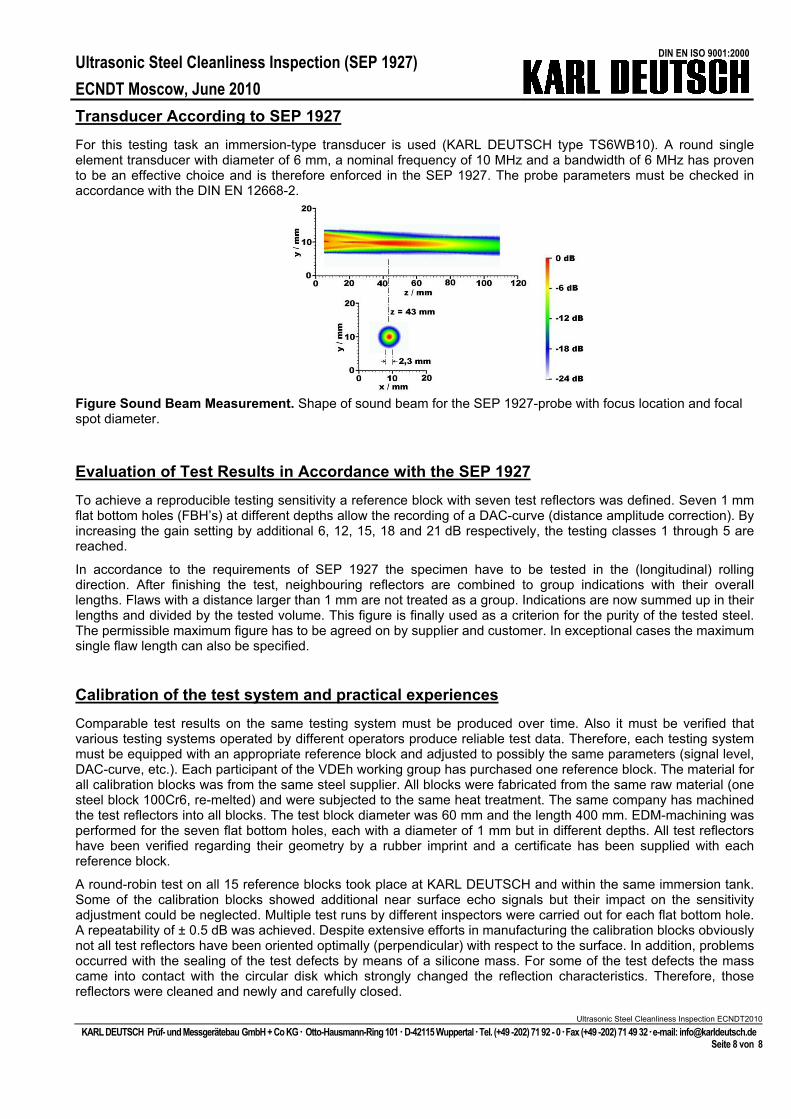
For this testing task an immersion-type transducer is used (KARL DEUTSCH type TS6WB10). A round single element transducer with diameter of 6 mm, a nominal frequency of 10 MHz and a bandwidth of 6 MHz has proven to be an effective choice and is therefore enforced in the SEP 1927. The probe parameters must be checked in accordance with the DIN EN 12668-2.
Figure Sound Beam Measurement. Shape of sound beam for the SEP 1927-probe with focus location and focal spot diameter.
Evaluation of Test Results in Accordance with the SEP 1927
To achieve a reproducible testing sensitivity a reference block with seven test reflectors was defined. Seven 1 mm flat bottom holes (FBH’s) at different depths allow the recording of a DAC-curve (distance amplitude correction). By increasing the gain setting by additional 6, 12, 15, 18 and 21 dB respectively, the testing classes 1 through 5 are reached.
In accordance to the requirements of SEP 1927 the specimen have to be tested in the (longitudinal) rolling direction. After finishing the test, neighbouring reflectors are combined to group indications with their overall lengths. Flaws with a distance larger than 1 mm are not treated as a group. Indications are now summed up in their lengths and divided by the tested volume. This figure is finally used as a criterion for the purity of the tested steel. The permissible maximum figure has to be agreed on by supplier and customer. In exceptional cases the maximum single flaw length can also be specified.
Calibration of the test system and practical experiences
Comparable test results on the same testing system must be produced over time. Also it must be verified that various testing systems operated by different operators produce reliable test data. Therefore, each testing system must be equipped with an appropriate reference block and adjusted to possibly the same parameters (signal level, DAC-curve, etc.). Each participant of the VDEh working group has purchased one reference block. The material for all calibration blocks was from the same steel supplier. All blocks were fabricated from the same raw material (one steel block 100Cr6, re-melted) and were subjected to the same heat treatment. The same company has machined the test reflectors into all blocks. The test block diameter was 60 mm and the length 400 mm. EDM-machining was performed for the seven flat bottom holes, each with a diameter of 1 mm but in different depths. All test reflectors have been verified regarding their geometry by a rubber imprint and a certificate has been supplied with each reference block.
A round-robin test on all 15 reference blocks took place at KARL DEUTSCH and within the same immersion tank. Some of the calibration blocks showed additional near surface echo signals but their impact on the sensitivity adjustment could be neglected. Multiple test runs by different inspectors were carried out for each flat bottom hole. A repeatability of ± 0.5 dB was achieved. Despite extensive efforts in manufacturing the calibration blocks obviously not all test reflectors have been oriented optimally (perpendicular) with respect to the surface. In addition, problems occurred with the sealing of the test defects by means of a silicone mass. For some of the test defects the mass came into contact with the circular disk which strongly changed the reflection characteristics. Therefore, those reflectors were cleaned and newly and carefully closed.
Ultrasonic Steel Cleanliness Inspection (SEP 1927) ECNDT Moscow, June 2010
DIN EN ISO 9001:2000
Despite optimization of the specimen orientation and transducer positioning for each individual reflector, differences in signal height between 0.4 and 4 dB have been observed over the amount of calibration blocks. Since the SEP 1927 test classes change in 3 dB-steps, these deviations were not tolerable. Therefore, a master DAC-curve containing the average values was suggested. The deviations for each test block and each reflector were recorded and are then taken into account during system calibration. It was concluded that this approach yields a stable establishment of DAC-curves (and corresponding sensitivity setting) for the testing systems.
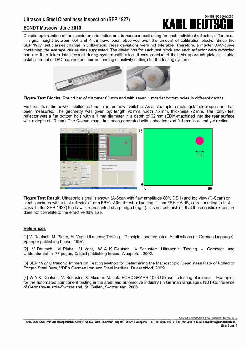
Figure Test Blocks. Round bar of diameter 60 mm and with seven 1 mm flat bottom holes in different depths.
First results of the newly installed test machine are now available. As an example a rectangular steel specimen has been measured. The geometry was given by: length 90 mm, width 75 mm, thickness 72 mm. The (only) test reflector was a flat bottom hole with a 1 mm diameter in a depth of 62 mm (EDM-machined into the rear surface with a depth of 10 mm). The C-scan image has been generated with a shot index of 0.1 mm in x- and y-direction.
Figure Test Result. Ultrasonic signal is shown (A-Scan with flaw amplitude 80% DSH) and top view (C-Scan) on steel specimen with a test reflector (1 mm FBH). After threshold setting (1 mm FBH + 6 dB, corresponding to test class 1 after SEP 1927) the flaw is represented sharp edged (right). It is not astonishing that the acoustic extension does not correlate to the effective flaw size.
References
[1] V. Deutsch, M. Platte, M. Vogt: Ultrasonic Testing – Principles and Industrial Applications (in German language), Springer publishing house, 1997.
[2] V. Deutsch, M. Platte, M. Vogt, W. A. K. Deutsch, V. Schuster: Ultrasonic Testing – Compact and Understandable, 77 pages, Castell publishing house, Wuppertal, 2002. [3] SEP 1927 Ultrasonic Immersion Testing Method for Determining the Macroscopic Cleanliness Rate of Rolled or Forged Steel Bars, VDEh German Iron and Steel Institute, Duesseldorf, 2009. [4] W.A.K. Deutsch, V. Schuster, K. Maxam, M. Lok: ECHOGRAPH 1093 Ultrasonic testing electronic – Examples for the automated component testing in the steel and automotive industry (in German language), NDT-Conference of Germany-Austria-Switzerland, St. Gallen, Switzerland, 2008.
Ultrasonic Steel Cleanliness Inspection ECNDT2010
KARL DEUTSCH Prüf- und Messgerätebau GmbH + Co KG Otto-Hausmann-Ring 101 D-42115 Wuppertal Tel. (+49 -202) 71 92 - 0 Fax (+49 -202) 71 49 32 e-mail: [email protected] Seite 9 von 9