Embed Size (px)
Citation preview
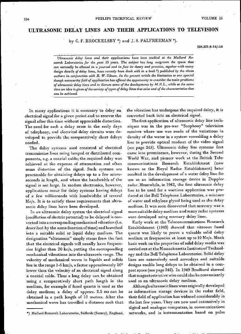
234 PIIILIPS TECHNICAL REVIEW VOLUME 25
ULTRASONIC DELAY LINES AND THEIR APPLICATIONS TO TELEVISION
by C. F. BROCKELSBY *) and J. S. PALFREEMAN *).
Ultrasonic delay lines and their applications have been studied at the Mullard Re-search Laboratories for the past 15 years. The subject has long outgrown the space thatcan normally be allowed in a journal and in fact its tl~eoryand practice, together with manydesign details of delay lines, have recently been dealt with in a book 2) published by the aboveauthors in c~njunction with R. W. Gibson. In the present article the limitation to one specialthough noteworthy field of application has offered the opportunity to consider the main problemsofultrasonic delay lines and to discuss some of the developments by M.R.L., while at the sametime an idea is given of the variety of types of delay lines that exist and of the characteristics thatcan be achieved.
534.321.9-14/-16
In many applications it is necessary to delay anelectrical signal for a given period andto recover thesignal after this time without appreciable distortion.The need for such a delay arose in the early daysof telephony, and electrical delay circuits were de-veloped to provide the comparatively short delaysneeded.
The delay systems used consisted of electricaltransmission lines using lumped or distributed com-ponents, e.g. a coaxial cable; the required delay wasachieved at the expense of attenuation and oftensome distortion of the signal. Such systems arepracticable for obtaining delays up to a few micro-seconds in length, and where the bandwidth of thesignal is not large. In modern electronics, however,applications occur for delay systems having delaysof a few milliseconds with bandwidths of severalMc/s. It is to satisfy these requirements that ultra-sonic delay lines have been developed.
In an ultrasonic delay system the electrical signal(oscillation of electric potential) to be delayed is con-verted into a corresponding mechanical vibration (i.e.described by the same function of time) and launched·into a suitable solid or liquid delay medium. Thedesignation "ultrasonic" simply stems from the factthat the electrical signals will usually have frequen-cies higher than 20 kc/s, putting the correspondingmechanical vibrations into the ultrasonic range. Thevelocity of mechanical waves in liquids and solidslies in the range 1-6 km/s, a factor approximately 105
lower than the velocity of an electrical signal alonga coaxial cable. Thus a long delay can be obtainedusing a comparatively short path length in themedium, for example if fused quartz is used as thedelay medium; a delay' of approx. 2.5 ms can beobtained in a path length of 10 metres. Mter themechanical wave has travelled a distance such that
*) Mullard Research Laboratories, Salfords (Surrey), England.
the vibration has undergone the required delay, it isconverted back into an electrical signal.
The first application of ultrasonic delay line tech-niques was in the pre-war "Scophony" televisionreceiver where use was made of the variations indensity of the water in a system resembling a delayline to provide optical readout of the video signal(see page 24,3). Ultrasonic delay line systems firstcame into prominence, however, during the SecondWorld War, and pioneer work at the British Tele-communications Research Establishment (nowknown as the Royal Radar Establishment) laterresulted in the development of a water delay line foruse as an information storage device in Dopplerradar. Meanwhile, in 1942, the first ultrasonic delayline to be used for a wartime application was pro-duced at the Bell Telephone Laboratories, a mixtureof water and ethylene glycol being used as the delaymedium. Itwas soon discovered that mercury was amore suitable delay medium and many radar systemswere developed using mercury delay lines.
Early work at the Telecommunications ResearchEstablishment (1943) showed that vitreous fusedquartz was likely to prove a valuable solid delaymedium at frequencies at least up to 10Mc/s. Muchbasic work on the properties of solid delay media wascarried out at the Massachusetts Institute of Technol-ogy and the Bell Telephone Laboratories, Solid delaylines are extensively used nowadays and suitabledesigns enable long delays to be obtained in a com-pact space (see page 242). In 1949 Bradburd showedthat magnetostrictive wire could also be convenientlyused as an ultrasonic delay medium.
Although ultrasonic lines were originally developedas information storage devices in the radar field,their field of application has widened considerably inthe last few years. They are now used extensively indigital and analogue computers, in communicationsnetworks, and in instrumentation based on pulse
1963/64, No. 9 ULTRASONIC DELAY LINES 235
J. THE DIFFERENT TYPES OF DELAY LINES, AND GENERAL CONSIDERATIONS 2)
timing 1). Several applications of ultrasonic delaytechniques occur in the field of television and thediscussion of ultrasonic delay lines in this article,after a general introduction to such lines, will con-
From the above it follows that an ultrasonic delayline consists basically of three components. Firstthere is a device known as a transducer which con-verts the electrical signal into a mechanical vibra-tion. Second there is the delay medium throughwhich the mechanical signal travels and undergoesthe required delay. Finally there is a second trans-ducer which converts the mechanical vibration intothe required electrical signal.
Ultrasonic delay lines may be divided into threemain categories, using wires, liquids, and extendedsolids respectively as the delay media. These threetypes ofline differ markedly in the mode ofvibrationemployed for transmission and hence in the form oftransducer required. Some principles of delay lineswill now be explained using the comparativelysimple wire line as an example. General considera-tions applying to liquid and solid lines will be givenafterwards, followed by some details of these lines.
Wire delay lines
In a wire delay line the electrical signal is con-verted into a mechanical oscillation of a magneto-strictive wire or tube. A magnetostrictive materialwill undergo reversible expansion or contraction inthe direction of an applied magnetic field, owing tointernal stresses arising as the magnetic dipoles arediverted from their preferred orientations. Con-verselya mechanical deformation of such a materialwill give rise to a magnetic flux. Thus by passing afluctuating current through a coil surrounding thewire a longitudinal meehamcal wave can be launcheddown the wire, and this wave can be detected at theoutput end of the line by another coil surroundingthe wire, the change of magnetic flux through thiscoil giving rise to the desired electrical signal.Magnetostriction isa square law effect, i.e, both posi-
tive and negative currents through the input coilwill
1) See for example H. A. Dell, D. S. Hobbs and M. S. Riohards.An antomatic particle counter and sizer, Philips tech. Rev.21, 253·267, 1959/60.
2) A detailed account of most of the information contaiued inthe first part of this article is given in the book: Ultrasonicdelay lines, by C. F. Brockelsby, J. S. Palfreeman andR. W. Gibson, published by Iliffe, London 1963. A list ofreferences to the literature on the history of delay lines audon many developments mentioned in this article is alsogiven in this book.
centra te on this group of applications (page 243 £f.).They are found to occur in the television studio, inthe research laboratory, and in some possible kindsof domestic receiver.
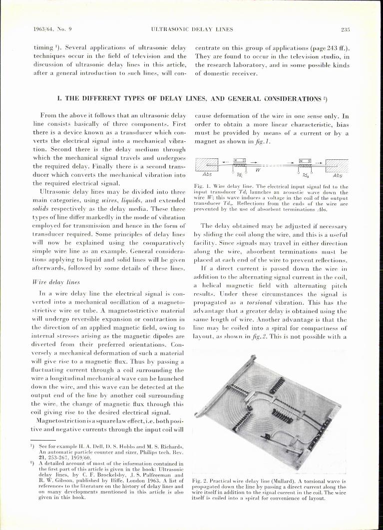
canse deforrnation of the wire in one sense only. Inorder to obtain a more linear characteristic, biasmust be provided by means of a current or by amagnet as shown in fig .1.
Fig. 1. Wire delay line. The electrical input signal fed to theinpnt transducer Til, lannches an acoustic wave down thewire W; this wave induces a voltage in the coil of the outputtransducer Ttl.; Reflections from the ends of the wire arcprevented by the use of absorbent terminations Abs,
The delay obtained may be adjusted if necessaryby slidiug the coil along the wire, and this is a usefulfacility. Since signals may travel in either directionalong the wire, absorbent terrnin a tions must beplaced at each cnd of the wire to prevent reflections.If a direct current is passed down the wire in
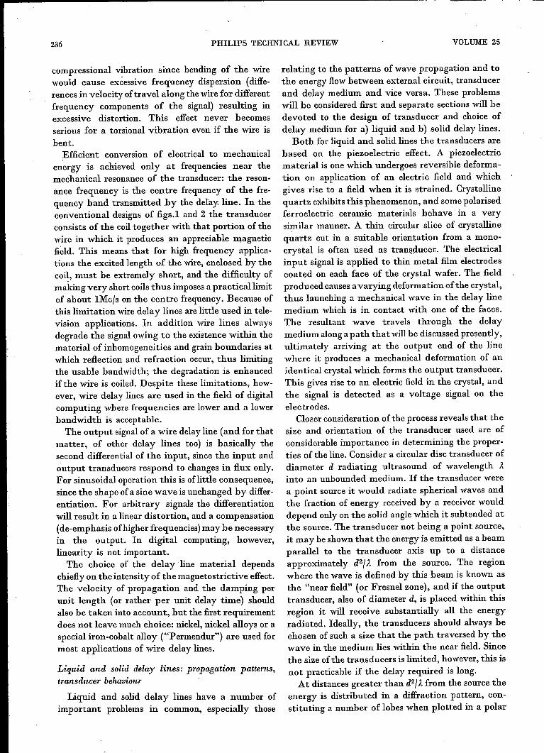
addition to the alternating signal current in the coil,a helical magnetic field with alternating pitchresults. Under these circumstances the signal ispropagated as a torsional vibration. This has theadvantage that a greater delay is obtained using thesame length of wire. Another advantage is that theline may be coiled into a spiral for compactness oflayout, as shown infig.2. This is not possible with a
Fig. 2. Practical wire delay line (Mullard). A torsional wave ispropagated down the line by passing a direct current along thewire itself in addition to the signal current in the coil. The wireitself is coiled into a spiral for convenience of layout.
236 PHILlPS TECHNICAL REVIEW VOLUME 25
compressional vibration since bending of the wirewould cause excessive frequency dispersion (diffe-rences in velocity of travel along the wire for differentfrequency components of the signal) resulting inexcessive distortion. This effect never becomesserious for a torsional vibration even if the wire isbent.Efficient conversion of electrical to mechanical
energy is achieved only at frequencies near themechanical resonance of the transducer: the reson-ance frequency is the centre frequency of the fre-quency band transmitted by the delay. line. In theconventional designs of figs.l and 2 the transducerconsists of the coil together with that portion of thewire in which it produces an appreciable magneticfield. This means that for high frequency applica-tions the excited length of the wire, enclosed by thecoil, must be extremely short, and the difficulty ofmaking very short coils thus imposes a practical limitof about lMcfs on the centre frequency. Because ofthis limitation wire delay lines are little used in tele-vision applications. In addition wire lines alwaysdegrade the signal owing to the existence within thematerialof inhomogeneities and grain boundaries atwhich reflection and refraction occur, thus limitingthe usable bandwidth; the degradation is enhancedif the wire is coiled. Despite these limitations, how-ever, wire delay lines are used in the field of digitalcomputing where frequencies are lower and a lowerbandwidth is acceptable.The output signalof a wire delay line (and for that
matter, of other delay lines too) is basically thesecond differential of the input, since the input andoutput transducers respond to changes in flux only.For sinusoidal operation this is oflittle consequence,since the shape of a sine wave is unchanged by differ-entiation. For arbitrary signals the differentiationwill result in a linear distortion, and a compensation(de-emphasis ofhigher frequencies) may be necessaryin the output. In digital computing, however,linearity is not important.
The choice of the delay line material dependschiefly on the intensity of the magnetostrictive effect.The velocity of propagation and the damping perunit length (or rather per unit delay time) shouldalso be taken into account, but the first requirementdoes not leave much choice: nickel, nickel alloys or aspecial iron-cobalt alloy ("Permendur") are used formost applications of wire delay lines.
Liquid and solid delay lines: propagation patterns,transducer behaviour
Liquid and solid delay lines have a number ofimportant problems in common, especially those
relating to the patterns of wave propagation and tothe energy flowbetween external circuit, transducerand delay medium and vice versa. These problemswill be considered first and separate sections will bedevoted to the design of transducer and choice ofdelay medium for a) liquid and b) solid delay lines.
Both for liquid and solid lines the transducers arebased on the piezoelectric effect. A piezoelectricmaterial is one which undergoes reversible deforma-tion on application of an electric field and whichgives rise to a field when it is strained. Crystallinequartz exhibits this phenomenon, and some polarisedferroelectric ceramic materials behave in a verysimilar manner. A thin circular slice of crystallinequartz cut in a suitable orientation from a mono-crystal is often used as transducen, The electricalinput signal is applied to thin metal film electrodescoated on each face of the crystal wafer. The fieldproduced causes avarying deformation of the crystal,thus launching a mechanical wave in the delay linemedium which is in contact with one of the faces.The resultant wave travels through the delaymedium along a path that will be discussed presently,ultimately arriving at the output end of the linewhere it produces a mechanical deformation of anidentical crystal which forms the output transducer.This gives rise to an electric field in the crystal, andthe signal is detected as a voltage signalon theelectrodes.
Closer consideration of the process reveals that thesize and orientation of the transducer used are ofconsiderable importance in determining the proper"ties of the line. Consider a circular disc transducer ofdiameter d radiating ultrasound of wavelength Itinto an unbounded medium. If the transducer werea point source it would radiate spherical waves andthe fraction of energy received by a receiver woulddepend only on the solid angle which it subtended atthe source. The transducer not being a point source,it may be shown that the energy is emitted as a beamparallel to the transducer axis up to a distanceapproximately d2flt from the source. The regionwhere the wave is defined by this beam is known asthe "near field" (or Fresnel zone), and if the outputtransducer, also of diameter d, is placed within thisregion it will receive substantially all the energyradiated. Ideally, the transducers should always bechosen of such a size that the path traversed by thewave in the medium lies within the near field. Sincethe size of the transducers is limited, however, this isnot practicable if the delay required is long.
At distances greater than d2flt from the source theenergy is distributed in a diffraction pattern, con-stituting a number of lobes when plotted in a polar
1963/64, No. 9 ULTRASONIC DELAY LINES 237
diagram. This region is known as the "far field" (orFraunhofer zone). Most of the vibration energy iscontained in the principal lobe of this pattern, andthe output transducer must be positioned to receivethis lobe. It will then receive a fraction of thetransmitted energy which is directly proportional tothe area of the transducer and inversely proportionalto the square of its distance from the source; thefraction of energy received is thus proportional tothe solid angle which the receiver subtends at thesource, but it is still much larger than that which itwould receive from a point source.
In order for the incident signal to produce adisturbance which is in phase at all points across theface of the output transducer, this device must healigned approximately normal to the incident beam.This situation, however, is not strictly necessary.More generally, a polar diagram can also be drawnfor the response of the output transducer, makingthe situation entirely symmetrical: in fact it may bedemonstrated that the energy transfer through adelay system is independent of which transducer isthe input and which is the output.
In order to obtain the required delay, the pathtraversed by the wave in the medium may need tobe several metres long; to obtain a straight path ofthis length is often difficult and sometimes impossible.For this reason a "folded" path must be used, inwhich the signal is deliberately made to undergoreflections from the boundaries ofthe medium duringits passage from input to output. At each reflectionthe shape of the diffraction pattern is slightly alteredbut in practice such changes may usually beneglected. Each reflection may be regarded asspecular, and the delay system may be approximatedby a model in which the two transducers are sepa-rated by a distance equal to the total path traversedby the wave in the medium.
Since d2JA is the governing parameter, the transi-tion from near field to far field will be seen to occurat larger distances the higher the frequency. In otherwords the principallobe of the propagation patternwill be narrowest for the highest frequencies con-tained in a signal and this will cause a relative lossof low frequency intensity received at the outputwhen the wave has travelled a long distance in thedelay medium. On the other hand a certain amountof the wave energy is dissipated in the mediumowing to viscous damping and thermal effects, andin solids losses also occur due to scattering of thesignal by inhomogeneities in the medium. Theselosses in all cases increase with frequency, in somecases even according to a square Iaw (see page 240),entailing a relative loss of high frequencies at long
delays. Both effects combined are responsible for afundamental limitation of delay lines: long delayscan only be achieved at the expense of useful band-width. However, the bandwidth is also limited byseveral other factors, which will be discussed below.
Since in the far field some ofthe energy transmittedis contained in the minor lobes of a diffraction pat-tern, it is possible for signals to arrive at the outputhaving traversed paths different from that definedfor the main signal. If these "secondary" signalshappen to be incident at an angle corresponding toone of the minor lobes of the output transducer polardiagram they will be detected; these signals have ingeneral undergone delays different from that ex-perienced by the main signal and thus constitute asource of interference which may be particularlynoticeable in lines where many reflecting surfacesare present, and in lines where the attenuation isappreciable: secondary signals which have travelledon a much shorter path than the main signal will thenhave a relative advantage. One task of the delay linedesigner is to minimise these spurious signals: theyshould be at least 50 dB weaker than the wantedsignal. This may be achieved by using transducers ofthe largest lateral dimensions conveniently practic-able, in order to confine most of the energy trans-mitted and received to the principallobe of the polardiagram of each transducer; some improvement mayalso be obtained by putting absorbent materialonwalls of the delay line which cause particularlytroublesome reflections, or by grinding these facesaway to alter the direction of the reflection wave.One commonly encountered unwanted signal is
the "third-time-round" signal which is reflected bythe output transducer, returns by the same path tothe input, and is reflected back to the receiver again.This signal can be reduced to negligible amplitudeat any particular frequency by tilting the outputtransducer through a small angle e. This angle ischosen so that, while the main signal still falls withinthe principal lobe of the output transducer polardiagram, the angle of -incidence of the third-time-round signal (3 e) corresponds to the first minimumof this polar diagram. This will only be effective fora narrow frequency band since the angular spacingof the lobes of the diffraction pattern depends on thefrequency.
Other important considerations common to bothliquid and solid delay lines, as stated above, refer tothe behaviour of the transducers and their couplingto the delay medium. This will be very roughlydescribed in the following paragraphs. The subject israther complex and a full treatment would requiremuch more space than can be allowed here.
238 PIULIPS TECHNICAL REVIEW VOLUME 25
In the static or quasistatic case (i.e. at lowfrequencies) a constant fraction k2 of the electricalenergy supplied to a piezo-electric crystal is storedas elastic energy in the deformed crystal; k is calledthe electromechanical coupling coefficient of thetransducer material. On first sight it would seemthat for efficient energy conversion at any frequency,k should be as large as possible. This condition, how-ever, is neither sufficient nor necessary. That it is notsufficient is seen by considering the mechanicalresponse of the crystal wafer to a given electricalinput. The response will be greatest (i.e. resonancewill occur) when the wafer thickness, .measured inthe direction of propagation, is equal to half thewavelength (or an odd multiple of it) of the ultra-sound in the transducer material. If the thickness isan even multiple of it, the response is zero and thusa transducer chosen to give maximum response ate.g.10Mc/s will give zero response (and zero energyconversion) at 20Mc/s - whatever its value of k.On the other hand it can be seen that a high k is notstrictly necessary. A transducer crystal may berepresented very approximately by a capacitance inparallel with a resistance representing tbe mechanicalstrain energy flowing out from the crystal (radiationresistance). No energy is dissipated in the systemeven when k is low, since the portion of the electricalenergy which is not converted into mechanical strainenergy is stored in the transducer capacitance andreleased when this capacitance is discharged.
Thus, k is not a direct measure of the efficiency ofa transducer, this depending in addition on theinternallosses and externalloading of the transducercrystal, and should be discussed in terms of energyflow. Nevertheless, the coupling coefficient k is offundamental importance and controls some aspectsof transducer performance.In the first place, if k is low (i.e. k2 ~ 1) then the
effect of the electrical terminations on the behaviourof the transducer may be neglected. If the voltagedrive is constant then the mechanical response of thetransducer at the resonant frequency is determinedby the ratio of the "acoustic impedance" of themedium to that ofthe transducer. For a progressivewave the acoustic impedance of a material is definedas the complex ratio of the stress in the medium atany point to the "particle" velocity, and is directlyanalogous to impedance in electrical systems. Thespecific acoustic impedance may be shown to beequal to the product of the density of the mediumand the velocity of the acoustic wave 3). Thus, if the
3) T. F. Hueter and R. H. Bolt, Sonics,Wiley, New York1955.
coupling coefficient k is low, the acoustic response atthe resonant frequency is determined by the relativedensities of the transducer and delay medium andthe relative velocities of the acoustic wave in the twomaterials.
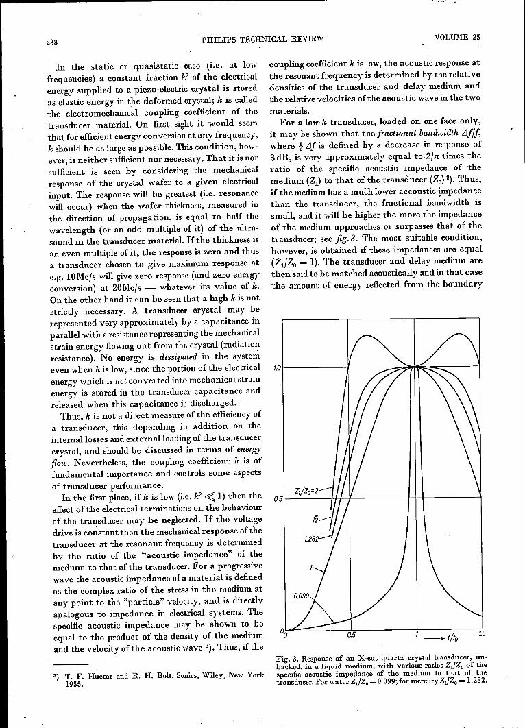
For a low-k transducer, loaded on one face only,it may be shown that the fractional bandwidth LJflJ,where t,1f is defined by a decrease in response of3 dB, is very approximately equal to- 2111', times theratio of the specific acoustic impedance of themedium (Zl) to that of the transducer (Zo) 2). Thus,if the medium has a muèh lower accoustic impedancethan the transducer, the fractional bandwidth issmall, and it will be higher the more the impedanceof the medium approaches or surpasses that of thetransducer; see fig.3. The most suitable condition,however, is obtained if these impedances are equal(Zl1Zo = 1). The transducer and 'delay medium arethen said to be matched acoustically and in that casethe amount of energy reflected from the boundary
%~~==~---4~--------~1--------~1.5-fifa
Fig. 3. Response of an X-cut quartz crystal transducer, un-backed, in a liquid medium, with various ratios Zl/ZO of thespecific acoustic impedance of the medium to that of thetransducer. For water Zl/ZO = 0.099;for mercury Zl/ZO = 1.282.
1963/64, No. 9 ULTRASONIC DELAY LINES
between them is zero. Any energy which is reflectedfrom the face of the output transd~cer produces nooutput and is not detected at the output except asan unwanted signal (the "third-time-round" signalmentioned above). This troublesome effect, there-fore, is minimised by the acoustical matching. Thefractional bandwidth in this case evidently is givenby 21n,which is a sizeable portion of the ideal value 2that would be permitted by the resonance behaviourof the vibrating wafer considered above (cf. theexample of maximum response at lOMcis, when theresponse can differ from zero in the band between 0and 20Mc/s).When using the concept of energy flow the
mechanical wave entering the output transducershould also be considered. Part of its energy will beused for producing the output signal, but in a low-kmaterial a relatively large part of the wave energywill not be made use of in this way and will proceedto the back of the transducer. If this face is loadedwith a materialof negligible acoustic impedance,such as air, then energy which is incident on thisface is almost totally reflected and may again giverise to a third-time-round signal. In a practical delayline it is therefore often desirable to "back" the
Liquid delay lines: delay medium and designMechanical vibrations in liquids can only be sup-
ported in a compressional mode, torsional or shearoscillations being impossible. An X-cut crystallinequartz wafer undergoes a compressional changeunder the influence of an electrical field and maytherefore be used as a transducer in a delay lineemploying a liquid delay medium.The choice of the liquid delay medium is deter-
mined by its acoustical properties and by those ofthe transducer. The attenuation of most liquids istoo high; apart from the liquefied monatomic gases,only mercury, water, and the lower alcohols have alow enough attenuation. In addition, since the valueof k, the electromechanical coupling coefficient, isonly 0.1 for crystalline quartz, a large fractionalbandwidth can only be obtained if the specificacoustic impedance of the transducer is similar tothat of the delay medium. In this case this require-ment means that the transducer must be loaded witha medium of high density. It is found that mercuryand crystalline quartz are approximately matchedacoustically.Since mercury is a conductor, it is only necessary
for the back of the transducer to be coated with atransducer with an absorbent medium of acoustic gold film electrode. The other electrode of the trans-impedance similar to that of the transducer. ducer consists of the mercury in contact with the
When the coupling coefficient k is high, the electro- front face.mechanical response of the transducer depends not Ferroelectric ceramic transducers have higheronly on the ratio of the acoustic impedances but also'--valuGs-Gf-t1leelectromechanical coupling coefficient,on the electrical terminations of the system. In this typical values being 0.45 for compressional wavescase acoustical matching is not so important since an and 0.65 for shear waves. However, these materialsappreciable part of the mechanical power is usually have the disadvantage that it is very difficult toconverted into electrical output power and for this obtain the extremely thin samples necessary for usereason is not liable to reflection. at very high frequencies. For this reason the practical
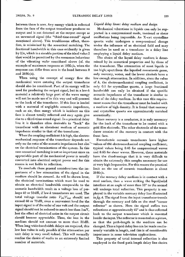
To conclude these general considerations the im- limit on the use of ceramic transducers is aboutportance of a low attenuation of the signal in the 20Mc/s.medium should be stressed. As will be shown later, If the mercury delay medium is in contact with athe electrical terminations which must be used to steel surface, then a wave striking the liquid/solidobtain an electrical bandwidth comparable to the interface at an angle of more than 10° to the normalacoustic bandwidth result in a voltage loss of per- will undergo total reflection. This property is em-haps 4·0or 50dB, if low-k transducers are used. The ployed in the variable mercury delay line illustratedtotal voltage transfer ratio VinlVout should not infigA. The signal from the input transducer travelsexceed 60 or 70dB, since a convenient level for the through the mercury and falls on the steel "cornerinput signal is of the order of one volt and the output reflector" as shown. Here the signal suffers twosignal should not be reduced to much less than 1mV, reflections at approximately 45° and is thus reflectedlest the effect of electrical noise in the output circuit back to the output transducer which is mountedshould become appreciable. Thus, the loss in the beside theinput. The reflector ismounted on a piston,medium should not amount to more than 20dB. so that the path-length in the medium can beWhen long wide-bandwidth delays are required, this changed. Thus aliquid delay line can be made contin-low loss value is only possible if the attenuation per uously variable in length, and this is of considerablèunit delay is very small indeed. This will normally importance in some television applications.confine the choice of media to an extremely limited This property of total internal reflection is alsonumber of materials. employed in the fixed path length delay line shown
239
240 PHILIPS TECHNICAL REVIEW VOLUME 25
a
b
Fig. 4,. et) Variable mercury delay line, with lid removed. b) Path of waves in the line. Til,input transducer, Tdo output transducer. The delay is varied by changing the position of thecorner reflector Reft, mounted on a sliding piston driven by a precision lead screw S. Thisscrew is cut with the exact pitch to make 1 revolution correspond to 10 f1.schange ofdelay. W driving wheel. C revolution counter. (Photograph from: C. F. Brockelsby, Ultra-sonic mercury delay lines, Electronic and B.adio Engr. 35,446-4.52, 1958.)
in fig. 5. In this system many reflections occur as thesignal traverses its "billiard table" path from inputto output and a comparatively long path can beobtained in a reasonably small space.The classical theory of absorption of sound III
liquids predicts an attenuation constant which isproportional to the square of the frequency. Themolecules of most liquids have rotational andvibrational degrees of freedom which are neglectedby classical theory, and which result in attenuationconstants higher than those predicted. Mercury how-ever ismonatomic and agrees wellwith the theoreticalpredictions at frequencies below SOMc/s.It is the quadratic variation of the attenuation
constant which limits the frequency at which a givendelay can be obtained in a practical system usingmercury as the delay medium. As the transducerresonant frequency is raised, the fractional band-width of the line at first remains constant. As thefrequency is raised further, however, the mercuryattenuation at the high frequency extremity of thepassband becomes increasingly significant; this bothlimits the bandwidth and depresses the frequency
of maximum response to a value below the crystalfrequency. Thus at television frequencies long delaysare difficult to obtain if the required bandwidth is tobe preserved. The characteristics of some typicalmercury delay lines, including those illustrated infigures 4 and 5, are given in Table Ion page 241.
Solid delay lines: delay medium and design
Solid materials are, in general, capable of support-ing two types of vibration, namely compressionalwaves and shear waves. In a solid ultrasonic delayline shear waves are chosen for two reasons. First,shear waves travel more slowly through a solidmedium than compressional waves, and thus alonger delay may be obtained in a given path length.Second, and more important, when a dilatationalwave is reflected from the boundary of the delaymedium then in general shear waves are alsogenerated. These waves are propagated in a directiondifferent from that taken by the reflected corn-pressional wave, and travel through the mediumwith a different velocity; they may thus give rise tospurious signals at the output transducer. If shear
1963/64, No. 9 ULTRASONIC DELAY LINES
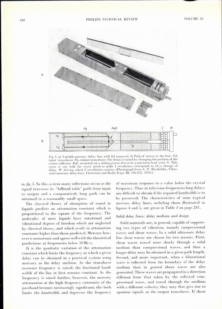
Table I. Physical and electrical characteristics of some typical liquid and solid delay lines suitable for use IJl television ap-plications.
IDelay Transducers Delay Band- Bandwidth Insertion Input and Largest spurious
medium centre loss output signal, dB belowVin/Vout capacitance wanted signal
fls Mc/s Mc/s dB pF
Mercury X-cut I 25 15 6 65 31 46quartz crystal
" " 30-330 *) 14.3-15.5 6.8-7.6 61-65 31 35" " 1000 **) 7.5 3 69 44 33
Fused quartz Y-cut 33.3 59 28 48 80 50quartz crystal
" " 2500 29 7 38 180 40Lime soda Lead zirconate- 64- 4..4- 2.5 10-20 ***) 1000-2000 ***) 40glass titanate type
Piezoxide 3I
*) Illustrated in fig.3.**) Illustrated in fig.4-.
***) The insertion loss of this line depends on source and termination impedances; the capacitances vary widely over thepassband.
waves are used initially, however, and are polarisedparallel to the reflecting surface (i.e. normal to theplane of incidence of the wave on the reflecting sur-face), then they are simply reflected at each impactwith no such "mode conversion". The geometricaldesign of the delay line configuration is therebygreatly simplified.The piezoelectric transducer used to generate the
shear vibration normally consists of a Y-cut crystal-line quartz wafer; alternatively a polarised ferro-electric material can be used. The transducer iscoated on both faces with metal film electrodes asbefore and bonded on one face to the delay mediumby means of a material which should be acousticallymatched to both the transducer material and thedelay medium. Indium is often used to make thebond because it has good adhesive properties and itsacoustic impedance has a suitable value.Consider now the choice of the medium. Single
crystals are difficult to use since their elastic con-stants are not normally tbe same in all directions.Polycrystalline materials are unsuitable for wide-passband delay lines since the ultrasonic waves inter-act with the grain structure of the medium at highfrequencies causing scattering. The materialcurrentlyconsidered most suitable as a delay medium isvitreous silica (fused quartz), which has an extremelylow attenuation. For short delays mixed oxide glassmay be used, although the attenuation in thismedium is much greater and it cannot be made ashomogeneous as fused quartz.If large pieces are called for, even fused quartz is
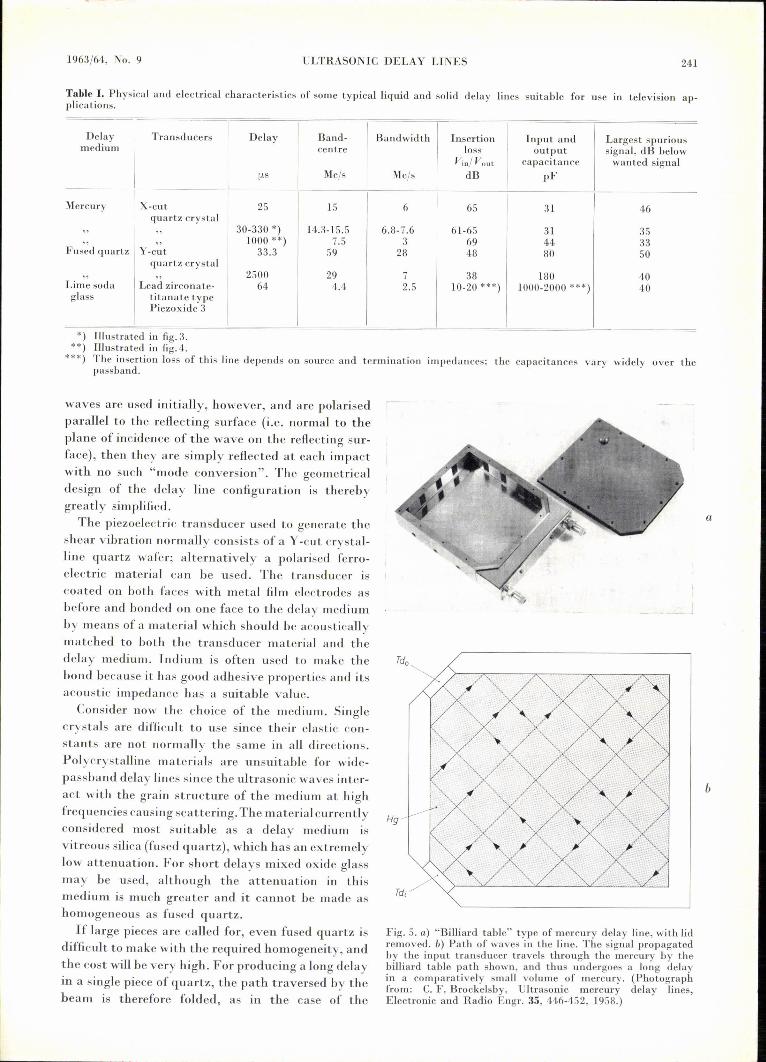
difficult to make with the required homogeneity, andthe cost will be very high. For producing a long delayin a single piece of quartz, the path traversed by thebeam is therefore folded, as in the case of the
Hg
Fig. 5. a) "Billiard table" type of mercury delay line, with lidremoved. b) Path of waves in the line. The signal propagatedby the input transducer travels through the mercury by thebilliard table path shown, and thus undergoes a long delayin a comparatively small volume of mercury. (Photographfrom: C. F. Brockelsby, Ultrasonic mercury delay lines,Electronic and Radio Engr. 35, 446-452, 1958.)
241
a
b
242 PHILlPS TECHNICAL REVIEW VOLUME 25
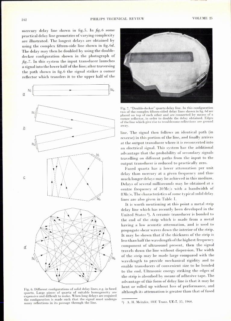
mercury delay line shown in fig.5. In fig.6 somepractical delay line geometries of varying complexityare illustrated. The longest delays are obtained byusing the complex fifteen-side line shown in fig.6d.The delay may then be doubled by using the double-decker configuration shown in the photograph offig.7. In this system the input transducer launchesa signal into the lower half of the line; after traversingthe path shown in fig.6 the signal strikes a cornerreflector which transfers it to the upper half of the
g ~i~~--------------••-----------------~~o
Fig. 6. Different configurations of solid delay lines, e.g. in fusedquartz. Large pieces of quartz of suitable homogeneity areexpensive and difficult to make. When long delays are requiredthe configuration is made such that the signal must undergomany reflections in its passage through the line.
Fig. 7. "Double-decker" quartz delay line. In this configurationtwo of the complex fifteen-sided delay lines shown in fig. 6d axeplaced on top of each other and are connected hy means of acorner reflector, in order to double the delay obtained. Edgesof the line which give rise to troublesome reflections are groundaway.
line. The signal then follows an identical path (inreverse) in this portion of the line, and finally arrivesat the output transducer where it is reconverted intoan electrical signal. This system has the additionaladvantage that the probability of secondary signalstravelling on different paths from the input to theoutput transducer is reduced to practically zero.Fused quartz has a lower attenuation per unit
delay than mercury at a given frequency and thusmuch longer delays may be achieved in this medium.Delays of several milliseconds may be obtained at acentre frequency of 30Mc/s with a bandwidth of8Mc/s. The characteristics of some typical solid delaylines are also given in Tablc I.It is worth mentioning at this point a metal strip
delay line which has recently been developed in theUnited States 4). A ceramic transducer is bonded tothe end of the strip which is made from a metalhaving a low acoustic attenuation, and is used topropagate shear waves down the interior of the strip.It may be shown that if the thickness of the strip isless than half the wavelength of the highest frequencycomponent of ultrasound present, then the signaltravels down the line without dispersion. The widthof the strip may be made large compared with thewavelength to provide mechanical rigidity and toenable transducers of convenient size to be bondedto the end. Ultrasonic energy striking the edges ofthe strip is absorbed by means of adhesive tape. Theadvantage of this form of delay line is that it may bebent or rolled up without loss of performance, andalthough its attenuation is greater than that of fused
4) A. H. Meitzler, IRE Trans. UE-7, 35, 1960.
1963/64, No. 9 ULTRASONIC DELAY LINES
quartz, a delay of 10 milliseconds has been achievedwith a video bandwidth of 2McJs.
as low as 75 O. (The capacitance of course must betuned to the crystal frequency by means of a parallelinductance.) The output of the delay line systemmay then be regarded as a constant current gen-
In order to obtain optimum performance from an erator, and the effect of the damping resistor is toultrasonic delay line it is necessary that the electrical produce a voltage insertion loss VinJVout whichsource and load impedances should be chosen".....depends largely on the ratio of termination imped-correctly. This choice is determined by the nature ance to source (transducer) impedance, and in thisof the transducers used and by their coupling to the case is of the order of 40dB. To reduce this voltagedelay medium. loss it is important to keep stray capacitance to aIt has already been mentioned that a transducer minimum and thus maximise the value ofthe damp-
for use with solid or liquid delay lines may be ing resistance necessary to produce the requiredrepresented very approximately by a capacitance in electrical bandwidth. A similar electrical bandwidthparallel with a resistance (in reality this is valid only is, of course, necessary for the driving circuit.at the centre of the passband). If the transducer is a In the case of ceramic transducers, which havequartz crystal which has a low value of the coupling high coupling coefficients, the effect of a parallelcoefficient k, this effective parallel resistance is very damping resistor is by no means so simple. Thehigh compared with the reactance of the transducer shunt radiation resistance of the transducer is nowcapacitance within the passband, and, as previously comparable with the reactance of the capacitor andstated, the acoustic response of the line is not both vary appreciably over the passband. Thesignificantly 'dependent on the electrical termina- optimum driving and receiving circuits can then be'tions.A satisfactory mechanicalbandwidth (fractional predicted exactly only by laborious calculations; abandwidth 2Jn) is then achieved by acoustical good account of the effect ofelectrical and mechanicalmatching of transducer and delay medium. The terminations on the loss and bandwidth of delayelectrical circuit of which the trandsucer forms a systems using ceramic transducers is given bypart evidently should have at least the same band- Thurston 5).width. To this end it is necessary to damp the circuit The electrical characteristics of wire delay lines,with a shunt resistance (alternatively a suitable four- where coils are used as input and output transducers,terminal matching network may be used). A typical are entirely different from those of solid and liquidquartz transducer for a solid delay line may be lines. However, as previously mentioned, wire delayrepresented electrically by a 10kO resistance in lines are seldom used in television applications; forparallel with a 200pF capacitance. The damping this reason no further treatment of the relevantresistor required to terminate this system might be electrical circuitry will be given.
Input and output circuits
II. APPLICATIONS TO TELEVISION
1) The "Scophony" receiver In the "Scophony" receiver 6), the video informa-The earliest application of ultrasonic techniques in-. ·.tion corresponding to each line of the picture was
the field of television was in the pre-war "Scophony"mechanical scanning receiver, in which use was madeof the optical properties of a liquid delay line whenan ultrasonic signal was present in the line.A television picture is always transmitted as an
array of horizontallines. During one "field" periodthe video signal corresponding to every alternate linein the picture is transmitted, during the next fieldperiod the transmission consists of those linesomitted during the previous scan. The two sets oflines are "interlaced" by the receiver to describe thecomplete picture or "frame".
modulated onto a 10McJs carrier and applied to theinput transducer of a delay line, which used water asthe delay medium. Absorbent material was placed atthe çutput end of the line, since no electrical outputwas required. Under the influence ofthe carrier alonethe periodic variations in the density and hence inthe refractive index of the water cause it to behaveas a diffraction grating, the spacing of the lines beingequal to the wavelength of the ultrasound in the
6) R. N. Thurston, IRE Trans. UE.7, 16, 1960.6) J. H. Jeffree, 'Television 9, May 1936, p. 260, and British
Patent No. 439 236. .
243
2440 PHILlPS TECHNICAL REVIEW VOLUME 25
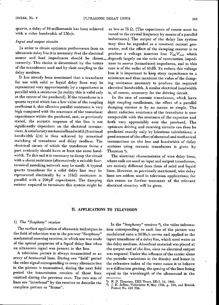
water. If a parallel beam of light is allowed to passthrough the medium, then the amount of light dif-fracted away from the zero order maximum intosubsidiary maxima by any part of the grating isproportional to the amplitude of the periodic varia-tions in the refractive index of the medium at thatpoint.The system used is illustrated infig.8. Light from
an illuminated slit is collimated to pass through thedelay line as a parallel beam. The 10Mcfs carrier,modulated with the picture information, is appliedto the delay line, which is of such a length as toaccomodate a wave train corresponding to one com-plete line of the picture. The signal corresponding toeach picture element causes an amount of light pro-portional to the amplitude of this signal to be dif-fracted away from the zero order maximum for thatsection of the delay line. The undeviated zero orderbeam which is thus modulated in intensity across itswidth, is focussed onto the screen of the receiver bya lens and rotating mirror system as shown. A givenprogressive picture point on the delay line is arrestedby the rotating mirror system to produce a stationarypicture point on the screen; this point will be presentfor the complete line duration, and the same appliesto other points of the picture line. A further rota lingmirror system, not shown in fig.8, is used to providethe "frame scan", i.e. to combine the successive linesof the picture to produce the complete display.The "Scophony" receiver suffered from all the
usual problems of mechanical scanning systems; thechief of these was the difficulty in synchronising theextremely high speed motor (30000 r.p.m.) whichdrives the rotating mirrors providing the stationarypicture. For this reason the "Scophony" receiver wassoon superseded by the electronic scanning receiversin use today. However, the principle of using ultra-
oF
Tdi
t
sonic techuiques in order to provide optical readoutof an electrical signal is still of interest as a means ofhigh speed data processing, for certain specialapplications. Bandwidths of40Mcfsmay be achieved,together with the facility of simultaneous display orinspection of bits of information fed in sequentiallyover a period of many microseconds. An applicationof such a technique will be described later in thesection on systems conversion.
2) Inertia compensation for a vidicon tube
Ultrasonic delay lines have been used by Hughes 7)(1961) to correct for effects due to moving objects inthe well known vidicon television camera tube. Inthis tube the light from the object in the field of viewof the camera falls on a photoconductive layer ofantimony trisulphide producing a pattern of con-ductivity which at any point corresponds to thebrightness of the picture observed. In order to con-vert this pattern into an electrical signal the photo-conductive layer is scanned by a beam of electrons,in two fields with interlaced lines as previouslydescribed.
Difficulty arises in the vidicon tube when theimage on the photoconductive layer is not erasedcompletely byeach scan. Owing to the finite decaytime of the layer, the signal obtained on scanningconsists of the new information plus a certainpercentage of the previous information. This effect,which is only noticeable under conditions of poorillumination, results in the "smearing" of the imageof a moving object.
Hughes has used the following method in order tocorrect for this effect. Part of the signal from eachline in a field was delayed by one field period(16.651ms on the US system) and subtracted fromthe signal due to the corresponding line on the next
field, which is the one ad-jacent to it in the picture.The fraction of the signalused for the correction was10-40%. Since this sig-nal is merely a correctionto the main signal, an ap-preciable improvementmay be obtained evenwhen using a low band-width delay line, and theline used was ofthe torsio-
s
nal magnetostrictive typewith a bandwidth of 600kcfs on a 800kcfs carrier.
Fig. 8.Display system of the "Scophony" television receiver (1936). A Hat light beam froma source F passes through the delay line D and is locally affected in rrrtensit.y by the waveoriginating from the video signal. The transmitted beam is focussed by lens LOll the screen S.Any progressive picture point in the line is arrested by the rotating mirror M to produce astationary picture point on the screen.
7) W. L. Hughes, IRE Trans.PGBC-7, No. 3, p. 8, 1961.
1963/64, No. 9 ULTRASONIC DELAY LINES 245
The correction was inadequate in that the signalshould ideally have been delayed by two field periodsand applied to the corresponding line on the nextframe. This would have been more difficult toachieve owing to the very long delay required. How-ever, although interlace was ignored in this way, andthe bandwidth was low, a useful reduction of smearwas achieved with this experimental system.An alternative form of television camera tube, the
image orthicon, employs a photoemissive cathodeand does not exhibit "smear". For this reason thevidicon is little used-in television broadcasting exceptunder conditions of high illumination or in applica-tions where its comparatively small size is ofadvantage. In addition, in a more recently developedtube of the vidicon type, the "Plumbicon" 8), leadoxide is used as the photoconductive material; inthis case the "smearing" effect is hardly noticeable.Thus it appears that smear correction will seldom benecessary in future television applications.
3) Vertical aperture correction
Ultrasonic delay line techniques mayalso be usedto correct for another fault of a television cameratube, viz vertical aperture distortion.
The electron beam in the pick-up tube as well as inthe picture tube must scan the discrete lines fromwhich the television picture is formed (say 405 linesper picture). The effective diameter of the scanningspot formed by the beam of electrons in the pick-uptube, however, cannot be made as small as would berequired for the ideal line width. Thus the signalgenerated when scanning one line is diluted withinformation from the adjacent lines. This effect isknown as vertical aperture distortion and willobviously reduce the definition of the picture pro-ducedin thereceiver. Ahorizontal aperture distortionalso exists: whereas the television transmitter isdesigned to have a bandwidth such that frequenciescorresponding to ~X 4·05changes from black to whitealong one picture line can be coped with, the diam-eter of the scanning spot overlapping several ofthese changes will prevent the resolution of all thesepicture elements in the receiver. This horizontaldistortion, which strongly resembles the effect of afinite slit width in scanning sound film or magnetictape recording, can be approximately corrected byuse of electronic circuits. Correction of the verticalaperture distortion, however, has to deal with theadmixture of information pertaining to pictureelements scanned one complete picture line period
8) E. F. de Haan, A. van der Drift and P. P. M. Schampers,The "Plumbicon", a new television camera tube, Philipstech. Rev. 25,133-151, 1963/64 (No. 6/7).
before or afterwards and is possible only by usingdelay line techniques.An extra-difficulty arises from the way in which
the picture is scanned. Since two fields are interlacedin order to describe one complete picture, or frame,it follows that in order to correct one line of a framefor the admixed information of adjacent lines, itwould be necessary to store the information not forone line (96 (.1.Son the 405 line 50cls system used inGreat Britain) but for one field period (20ms).For simplicity it is proposed first to ignore
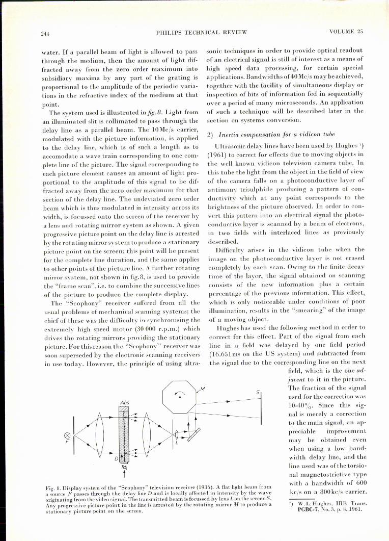
interlace and to correct each line with the informa-tion stored in the adjacent lines of the same field.To perform this correction at all adequately, eachline must be corrected with the signal due to thesubsequent line in the field as well as the precedingone. The system used is illustrated infig.9. The main
S(t)
- S(t-T)-0,2S(1)-0,2S(t-2T)
S(t-T)
Fig. 9. Vertical aperture correction using two "one-line" delaylines Dl and D2• The input signal S(t) delayed by one lineperiod T is used as the main signal, S(x-T). This signal is thencombined with 10-20% of the signal from the previous line,S(t-2T), which has been delayed by 2T, and the same pro-portion of the signal from the subsequent line, S(t), which hasundergone no delay.
signal is delayed by one line period, i.e. 96 (.1.s;fromthis is subtracted a part of the signal from thepreceding line of that field, which has undergone adelay of twice the line period, and part of the signalfrom the subsequent line, which is made available inadvance by bypassing the main delay line. Depend-ent on the vertical aperture distortion in the signal,the fraction of the signal from the adjacent linesneeded for the correction is 10-20%.
Since this correction involves delaying the mainsignal, the delay line used must be one with a band-width sufficient to accomodate the video informa-tion. For the 4.05-lihe, 50cIs system in which doublesideband modulation is used, the delay line musthave a bandwidth of 6Mc/s. In order to preventappreciable distortion, the frequency characteristicof the line should be flat to within 1dB over thewhole band. In addition, the delay line must bevariable in length if the line system is synchronisedto the mains, since the frequency of the mains maydrift appreciably. A variable ,mercury delay line is .suitable for this application and it is possible to use
246 PHILlPS TECHNICAL REVIEW VOLUME 25
a servo mechanism to adjust the length of the lineand to provide automatic control of the verticalaperture correction. If, however, the line system iscontrolled by a crystal-locked oscillator then noadjustment should be necessary and a solid delayline may be used.
Using the system described, a very marked im-provement in picture quality may be obtained.Gibson and Schroeder 9) (1960) and Howorth 10)(1962) have described systems ofthis kind. However,in order to perform this correction in the mosteffective manner interlace should not be ignored, andeach line should be corrected with information fromthe adjacent lines in the frame instead of the field.The system used should then be essentially the sameas that shown in fig.9 with the exception that thedelays involved are now equal to one field period(20ms).
Since this long delay is required for the mainsignal, which however should not suffer my loss ofdefinition, a rather difficult problem has to be solved.As previously mentioned, the most suitable delaymedium for providing long delays at large band-width is fused quartz. However, using existingtechniques, it is not possible to construct a singledelay line of 20ms delay even using fused quartz,since the path length required is 80 metres. A pieceof quartz of the required size and homogeneitycannot at the moment be obtained; in any case theattenuation in this path length would be too great.It is therefore necessary to use a number of shorterdelay lines to achieve this delay, with repeatingamplifiers to boost the signal after passage througheach section. A 20ms delay which has been made byMullm'd consists of eight lines each of 2.5ms dela y.This system has a bandwidth of 8Mc/s with a centrefrequency of 30Mc/s.
As previously stated, if the line system is syn-chronised to the mains frequency then the delayused must be variable. In order to achieve this, thecascade of quartz delay lines is made with a delayslightly less than 20ms. The remainder of the delayis provided by means of a short mercury delay linewhich may be fitted with a servomechanism to keepthe delay matched to the mains frequency, asdescribed above. This servomechanism might also beused to compensate for variations in temperature,although it is also possible to stabilise the tempera-ture at a constant value by use of a thermostat. Thisshould preferably be set to a value between 50 oe
9) W. G. Gibson and A. C. Schroeder, J. Soc. Motion Pictureand Television Engineers 69, 395, 1960.
10) D. Howorth, B.B.C. Research Department Report T-085,1962.
and 70 oe, since the attenuation in fused quartz islower in this temperature region than at room tem-perature.It would, incidentally, be possible to feed the
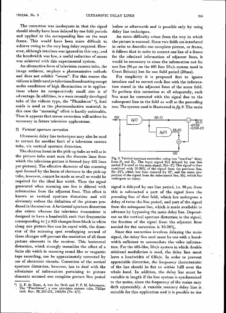
mechanical signal from the final section of the quartzdelay line directly into the mercury line without theuse of an intermediate repeater amplifier and the twoassociated transducers. This might be done as showninfig.lO. The shear wave in the quartz undergoes areflection at a plane such that the plane of incidenceis not normal but parallel to the polarisation of theshear wave, and at such an angle of incidence thatthe wave is converted entirely into a compressionwave. The resultant signal may now be used to prop-agate a compressional wave in the mercury whichis held in a steel container bonded to the end of thequartz.Since the delay line required for this ideal form of
vertical aperture correction is so complex, it wouldbe convenient if a single delay line could be used toprovide both the 20 millisecond delays needed. Infact, this may be done by using two separate carrier
Fig. 10. Combinationof a fused-quartz delay line with a variablemercury delay line. At the point A the plane and angle ofincidence of the vertically polarised shear wave in the fusedquartz delay line (Si02) are such that the signal is convertedentirely into a compression wave. This wave then passes directlyinto the mercury delay line, with reflector Rejll and adjustablecorner reflector Rejl 2, by means of which the delay of thecomposite !ine may be adjusted.
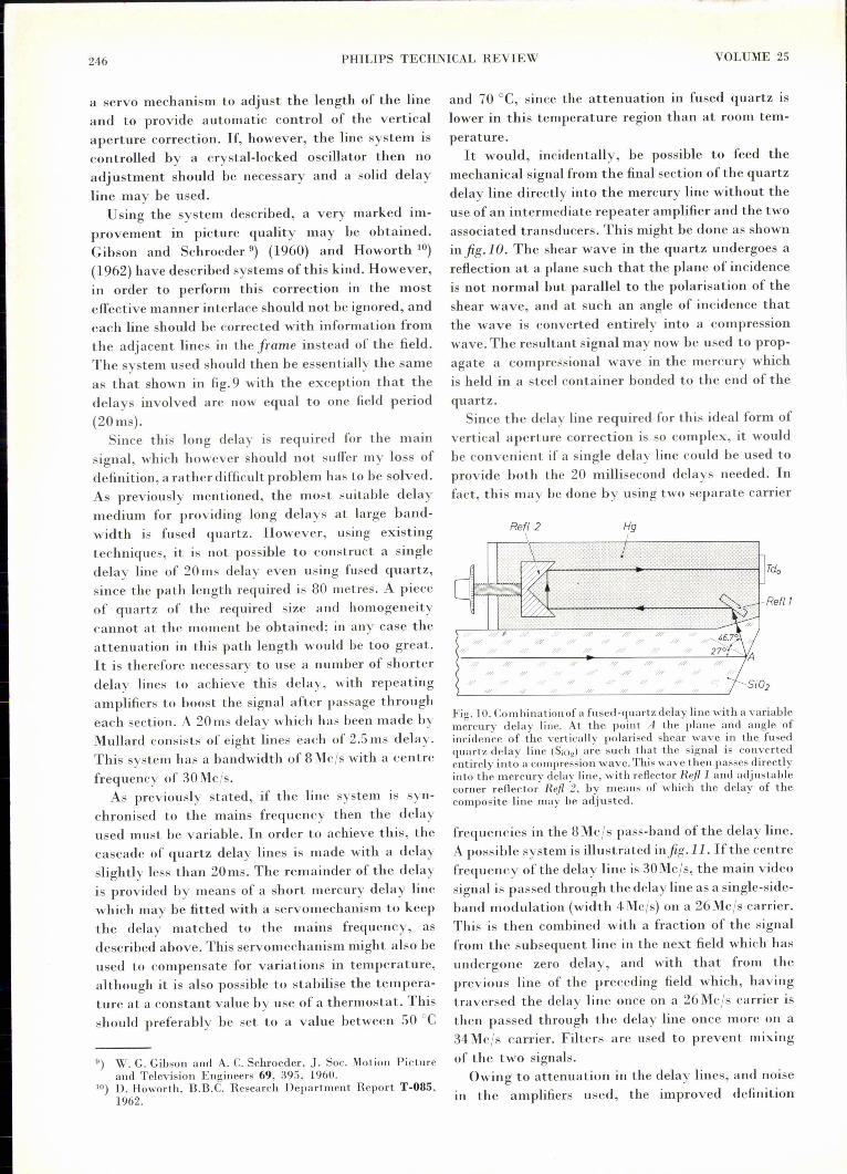
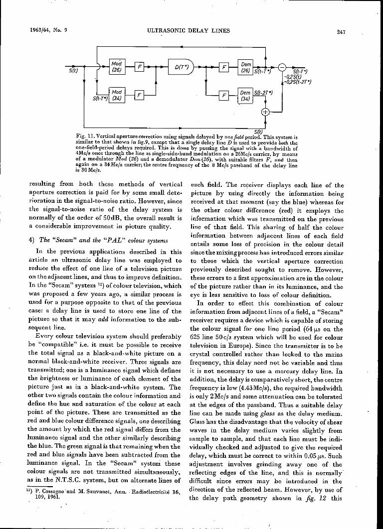
frequencies in the 8Mc/s pass-band of the delay line.A possible system is illustra ted in fig .11. If the centrefrequency of the delay line is 30Mc/s, the main videosignal is passed through the delay line as a single-side-band modulation (width 4Me/s) on a 26Mc/s carrier.Tbis is then combined with a fraction of the signalfrom the subsequent line in tbe next field which hasundergone zero delay, and with that from theprevious line of the preceding field which, havingtraversed the delay line once on a 26Mc/s carrier isthen passed through the delay line once more on a34Mc/s carrier. Filters are used to prevent mixingof the two signals.
Owing to attenuation in the delay lines, and noisein the amplifiers used, the improved definition
1963/64, No. 9 ULTRASONIC DELAY LINES 247
S(t)Fig. 11.Vertical aperture correction using signals delayed by one field period. This system issimilar to that shown in fig.9, except that a single delay line D is used to provide both theone-field-period delays required. This is done by passing the signal with a bandwidth of4Mc/s once through the line as single-side-band modulation on a 26Mc/scarrier, by meansof a modulator Mod (26) and a demodulator Dem (26), with suitable filters F, and thenagain on a 34Mc/s carrier; the centre frequency of the 8 Mc/s passband of the delay lineis 30Mc!s.
S(t)
resulting from both these methods of verticalaperture correction is paid for by some small dete-rioration in the signal-to-noise ratio. However, sincethe signal-to-noise ratio of the delay system isnormally of the order of 50dB, the overall result isa considerable improvement in picture quality.
4) The "Secam" and the "PAL" colour systems
In the previous applications described in thisarticle an ultrasonic delay line was employed toreduce the effect of one line of a television pictureon the adjacent lines, and thus to improve definition.In the "Secam" system 11) of colour television, whichwas proposed a few years ago, a similar process isused for a purpose opposite to that of the previouscase: a delay line is used to store one line of thepicture so that it may add information to the sub-sequent line.
Every colour television system should preferablybe "compatible" i.e. it must be possible to receivethe total signal as a black-and-white picture on anormal black-and-white receiver. Three signals aretransmitted; one is a luminance signal which definesthe brightness or luminance of each element of thepicture just as in a black-and-white system. Theother two signals contain the colour information anddefine the hue and saturation of the colour at eachpoint of the picture. These are transmitted as thered and blue colour difference signals, one describingthe amount by which the red signal differs from theluminance signal and the other similarly describingthe blue. The green signal is that remaining when thered and blue signals have been subtracted from theluminance signal. In the "Secam" system thesecolour signals are not transmitted simultaneously,as in the N.T.S.C. system, but on alternate lines of
11) P. Cassagne 'and M. Sauvanet, Ann. -Radioëlectricitë 16,109, 1961.
each field. The receiver displays each line of thepicture by using directly the information beingreceived at that moment (say the blue) whereas forthe other colour difference (red) it employs theinformation which was transmitted on the previousline of that field. This sharing of half the colourinformation between adjacent lines of each fieldentails some loss of precision in the colour detailsince the mixing process has introduced errors similarto those which the vertical aperture correctionpreviously described sought to remove. However,these errors to a first approximation are in the colourof the picture rather than in its luminance, and theeye is less sensitive to loss of colour definition.In order to effect this combination of colour
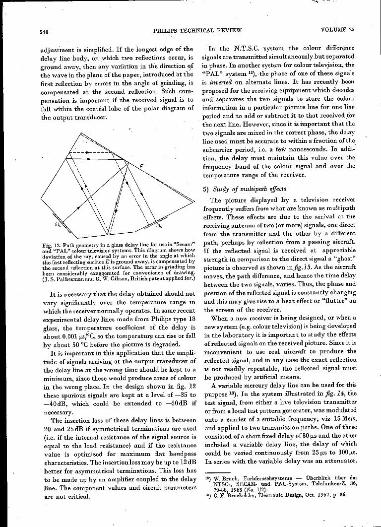
information from adjacent lines of a field, a "Secam"receiver requires a device which is capable of storingthe colour signal for one line period (64 [LS on the625 line 50cfs system which will be used for colourtelevision in Europe). Since the transmitter is to becrystal controlled rather than locked to the mainsfrequency, this delay need not be variable and thusit is not necessary to use a mercury delay line. Inaddition, the delay is comparatively short, the centrefrequency is low (4.43Mcfs), the required bandwidthis only 2Mcfs and some attenuation can be toleratedat the edges of the passband. Thus a suitable delayline can be made using glass as the delay medium.Glass has the disadvantage that the velocity of shearwaves in the delay medium varies slightly fromsample to sample, and that each line must be indi-vidually checked and adjusted to give the requireddelay, which must be correct to within 0.05 [LS. Suchadjustment involves grinding away one of thereflecting edges of the line, and this is normally'difficult since errors may be introduced in thedirection of the reflected beam. However, by use ofthe delay path geometry shown in fig. 12 this
248 PHILlPS TECHNICAL REVIEW VOLUME 25
adjustment is simplified. If the longest edge of thedelay line body, on which two reflections occur, isground away, then any variation in the direction ofthe wave in the plane of the paper, introduced at thefirst reflection by errors in the angle of grinding, iscompensated at the second reflection. Such corn-pensation is important if the received signal is tofall within the central lobe of the polar diagram ofthe output transducer.
\\\\\\\-..
\\\
Fig. 12. Path geometry in a glass delay line for use in "Secam"and "PAL" colour television systems. This diagram shows howdeviation of the ray, caused by an error in the angle at whichthe first reflecting surface E is ground away, is compensated bythe second reflection at this surface. The error in grinding hasbeen considerably exaggerated for convenience of drawing.(J. S. Palfreeman and R. W. Gibson, Britishpatent applied for.)
It is necessary that the delay obtained should notvary significantly over the temperature range inwhich the receiver normally operates. In some recentexperimental delay lines made from Philips type 18glass, the temperature coefficient of the delay isabout 0.001 !Jos;oC,so the temperature can rise or fallby about 50°C before the picture is degraded.
It is important in this application that the ampli-tude of signals arriving at the output transducer ofthe delay line at the wrong time should be kept to aminimum, since these would produce areas of colourin the wrong place. In the design shown in fig. 12these spurious signals are kept at a level of -35 to-40dB, which could be extended to -50dB ifnecessary.
The insertion loss of these delay lines is between20 and 25dB if symmetrical terminations are used(i.e. if the internal resistance of the signal source isequal to the load resistance) and if the resistancevalue is optimized for maximum flat bandpasscharacteristics. The insertion loss may be up to 12dBbetter for asymmetrical terminations. This loss hasto be made up by an amplifier coupled to the delayline. The component values and circuit parametersare not critical.
In the N.T.S.C. 'system the colour differencesignals are transmitted simultaneously but separatedin phase. In another system for colour television, the"PAL" system 12)" the phase of one of these signalsis inserted on alternate lines. It has recently beenproposed for the receiving equipment which decodesand separates the two signals to store the colourinformation in a particular picture line for one lineperiod and to add or subtract it to that received forthe next line. However, since it is important that thetwo signals are mixed in the correct phase, the delayline used must be accurate to within a fraction of thesubcarrier period, i.e. a few nanoseconds. In addi-tion, the delay must maintain this value over thefrequency band of the colour signal and over thetemperature range of the receiver.
5) Study of multipath effectsThe picture displayed by a television receiver
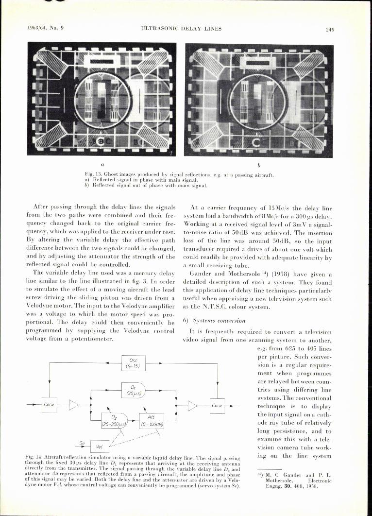
frequently suffers from what are known as multipatheffects. These effects are due to the arrival at thereceiving antenna oftwo (or more) signals, one directfrom the transmitter and the other by a differentpath, perhaps by reflection from a passing aircraft.If the reflected signal is received at appreciablestrength in comparison to the direct signal a "ghost"picture is observed as shown infig.13. As the aircraftmoves, the path difference, and hence the time delaybetween the two signals, varies. Thus, the phase andposition ofthe reflected signal is constantly changingand this may give rise to a beat effect or "flutter" onthe screen of the receiver.
When a new receiver is being designed, or when anew system (e.g. colour television) is being developedin the laboratory it is important to study the effectsofreflected signals on the received picture. Since it isinconvenient to use real aircraft to produce thereflected signal, and in any case the exact reflectionis not readily repeatable, the reflected signal mustbe produced by artificial means.
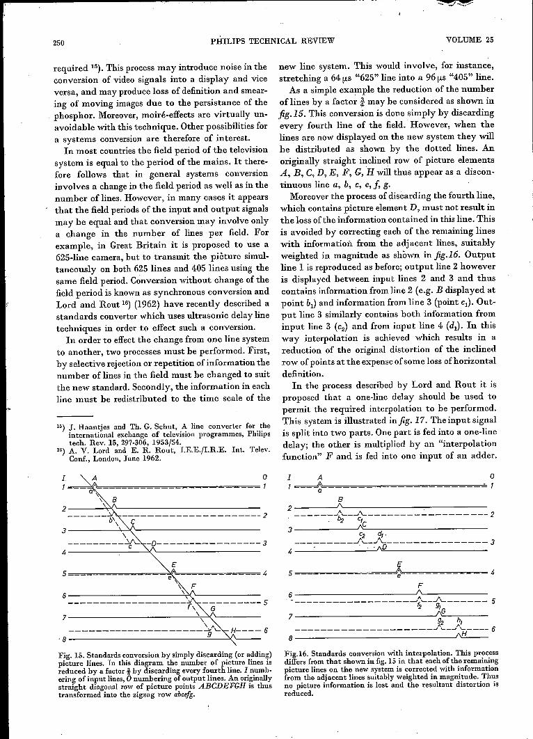
A variable mercury delay line can be used for thispurpose 13). In the system illustrated in fig. 14, thetest signal, from either a live television transmitteror from a local test pattern generator, was modulatedonto a carrier of a suitable frequency, viz 15Mc/s,and applied to two transmission paths. One of theseconsisted of a short fixed delay of 30 !JoSand the otherincluded a variable delay line, the delay of whichcould be varied continuously from 25!Josto 300!Jos.In series with the variable delay was an attenuator.
12) W. Bruch, Farbfernsehsysteme - Überblick über dasNTSC-, SECAM- und PAL-System, Telefunken-Z, 36,70-88, 1963 (No. 1/2).
13) C. F. Brockelsby, Electronic Design, Oct. 1957, p. 36.
1963/64, No. 9 ULTRASONIC DELAY LINES
Fig. 13. Ghost images produced by signal reflections, e.g. at a passing aircraft.a) Reflected signal in phase with main signal.b) Reflected signal out of phase with main signal.
a
After passing through the delay lines the signalsfrom the two paths were combined and their fre-quency changed back to the original carrier fre-quency, which was applied to the receiver under test.By altering the variable delay the effective pathdifference between the two signals could be changed,and by adjusting the attenuator the strength of thereflected signal could be controlled.
The variable delay line used was a mercury delayline similar to the line illustrated in fig. 3. In orderto simulate the effect of a moving aircraft the leadscrew driving the sliding piston was driven from aVelodyne 1110tor.The input to the Velodyne amplifierwas a voltage to which the motor speed was pro-portional. The delay could then conveniently beprogram med by supplying the Velodyne controlvoltage from a potentiometer.
Fig. 14. Aircraft reflection simulator using a variable liquid delay line. The signal passingthrongh the fixed 30 fLS delay line Dl represents that arriving at the receiving antennadirectly from the transmitter. The signal passing through the variable delay line D2 andattenuator Au represents that reflected from a passing aircraft; the amplitude and phaseof this signal may be varied. Both the delay line and the attenuator are driven by a Velo-dyne motor Vel, whose control voltage can conveniently be programmed (servo system Se).
0,(JO f1 sj
b
At a carrier frequency of 15Mc/s the delay linesystem bad a bandwidth of 8Mc/s for a 300 fLS delay.Working at a received signallevelof 3mV a signal-to-noise ratio of 50dB was achieved. The insertionloss of the line was around 50dB, so the inputtransducer required a drive of about one volt whichcould readily be provided with adequate linearity bya small receiving tube.Gander and Mothersole 14) (1958) have given a
detailed description of such a system. They foundthis application of delay line techniques particularlyuseful when appraising a new television system suchas the N.T.S.C. colour system.
6) Systems conversion
It is frequently required to convert a televisionvideo signal from one scanning system to another,
e.g. from 625 to 405 linesper picture. Such conver-sion is a regular require-ment when programmesare relayed between coun-tries using differing linesystems. The conventionaltechnique is to displaythe input signal on a cath-ode ray tube of relativelylong persistence, and toexamine this with a tele-vision camera tube work-ing on the line system
14) M. C. Gander and P. L.Mothersole, ElectronicEngng. 30, 408, 1958.
250 PHILIPS TECHNICAL REVIEW VOLUME 25
required 15). This process may introduce noise in theconversion of video signals into a display and viceversa, and may produce loss of definition and smear-ing of moving images due to the persistance of thephosphor. Moreover, moiré-effects are virtually un-avoidable with this technique. Other possibilities fora systems conversion are therefore of interest.
In most countries the field period of the televisionsystem is equal to the period of the mains. It there-fore follows that in general systems conversioninvolves a change in the field period as well as in thenumber of lines. However, in many cases it appearsthat the field periods of the input and output signalsmay be equal and that conversion may involve onlya change in the number of lines per field. Forexample, in Great Britain it is proposed to use a625-line camera, but to transmit the pièture simul-taneously on both 625 lines and 4·05lines using thesame field period. Conversion without change of thefield period is known as synchronous conversion andLord and Rout 16) (1962) have recently described astandards converter which uses ultrasonic delay linetechniques in order to effect such a conversion.
In order to effect the change from one line systemto another, two processes must be performed. First,by selective rejection or repetition of information thenumber of lines in the field must be changed to suitthe new standard. Secondly, the information in eachline must be redistributed to the time scale of the
15) J. Haantjes and Th. G. Schut, A line converter for theinternational exchange of television programmes, Philipstech. Rev. 15, 297-306, 1953/54.
16) A. V. Lord and E. R. Rout, I.E.E./I.R.E. Int. Telev.Conf., London, June 1962.
A
2------~L--------------------------------t ---------------------2, e3--------~~.L-----------------------
\---- ~/\_-C4--------------~L--------------------~----------------3
E5 --------------- "========= 4
e ~'\6----------------------~,~.~------------------------------7, -"6------- 5
7 " ,". 8 --------------------9 '- H---- 6
F
Fig. IS. Standards conversion by simply discarding (or adding)picture lines. In this diagram the number of picture lines isreduced by a factor! by discarding every fourth line. I numb-ering of input lines, 0 numbering of output lines. An originallystraight diagonal row of picture points ABCDEFGH is thustransformed into the zigzag row abcefg.
new line system. This would involve, for instance,stretching a 64 fLs"625" line into a 96 fLS"405" line.
As a simple example the reduction of the numberof lines by a factor! may be considered as shown infig. IS. This conversion is done simply by discardingevery fourth line of the field. However, when thelines are now displayed on the new system they willbe distributed as shown by the dotted lines. Anoriginally straight inclined row of picture elementsA, B, C, D, E, F, G, oHwill thus appear as a discon-tinuous line a, b, c, e, J, g.
Moreover the process of discarding the fourth line,which contains picture element D,must not result inthe loss of the information contained in this line. Thisis avoided by correcting each of the remaining lineswith information from the adjacent lines, suitablyweighted in magnitude as shown in fig.16. Outputline 1 is reproduced as before; output line 2 howeveris displayed between input lines 2 and 3 and thuscontains information from line 2 (e.g. B displayed atpoint bI) and information from line 3 (point Cl)' Out-put line 3 similarly contains both information frominput line 3 (c2) and from input line 4 (dl)' In thisway interpolation is achieved which results in areduction of the original distortion of the inclinedrow of points at the expense of some loss of horizontaldefinition.
In the process described by Lord and Rout it isproposed that a one-line delay should be used topermit the required interpolation to be performed.This system is illustrated infig. 17. The input signalis split into two parts. One part is fed into a one-linedelay; the other is multiplied by an "interpolationfunction" F and is fed into one input of an adder.
o I A 0l~====~=====o========la
B2 "~---A------------~-------------° -----~~'--~'-------------------2
. '2 le~~~------------------;2 ~I'_________ ~'-_J'- ~ 3
4' '. -,:=0 _
3
E5~==~====~==~=====~~===============~== 4
F~ "o'---~A---------------------------....Jf.'--J '------- 5
'2 91G7 '----;------
~2 ~I____________________ J '--~ '------ 6
8 ~H~ ___
Fig.16. Standards conversion with interpolation. This processdiffers from that shown in fig. 15 in that each of the remainingpicture lines on the new system is corrected with informationfrom the adjacent lines suitably weighted in magnitude. Thusno picture information is lost and the resultant distortion isreduced.
1963/64, No. 9 ULTRASONIC DELAY LINES 251
S(i)
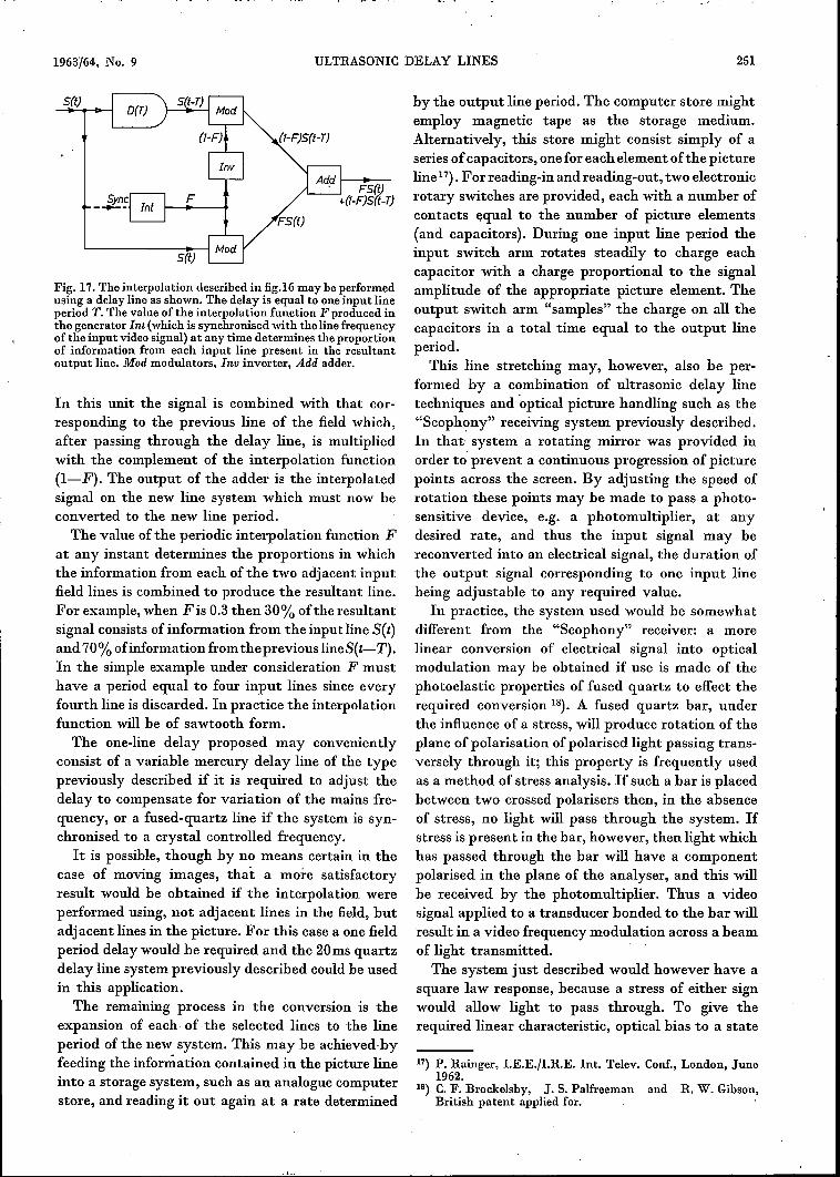
Fig. 17. The interpolation described in fig.16 may be performedusing a delay line as shown. The delay is equal to one input lineperiod T.The value of the interpolation function F produced inthe generator Int (which is synchronised with the line frequencyof the input video signal) at any time determines the proportionof information from each input line present in the resultantoutput line. Mod modulators, Inv inverter, Add adder.
In this unit the signal is combined with that cor-responding to the previous line of the field which,after passing through the delay line, is multipliedwith the complement of the interpolation function(I-F). The output of the adder is the interpolatedsignalon the new line system which must now beconverted to the new line period.
The value of the periodic interpolation function Fat any instant determines the proportions in whichthe information from each ofthe two adjacent inputfield lines is combined to produce the resultant line.For example, when Fis 0.3 then 30% ofthe resultantsignal consists of information from the inputline Set)and 70% ofiuformation from theprevious lineS(t-T).In the simple example under consideration F musthave a period equal to four input lines since everyfourth line is discarded. In practice the interpolationfunction will be of sawtooth form.
The one-line delay proposed may convenientlyconsist of a variable mercury delay line of the typepreviously described if it is required to adjust thedelay to compensate for variation of the mains fre-quency, or a fused-quartz line if the system is syn-chronised to a crystal controlled frequency.
It is possible, though by no means certain in thecase of moving images, that a more satisfactoryresult would be obtained if the interpolation wereperformed using, not adjacent lines in the field, butadjacent lines in the picture. For this case a one fieldperiod delay would be required and the 20ms quartzdelay line system previously described could be usedin this application.
The remaining process in the conversion is theexpansion of each of the selected lines to the lineperiod of the new system. This may be achieved byfeeding the information contained in the picture lineinto a storage system, such as an analogue computerstore, and reading it out again at a rate determined
by the output line period. The computer store mightemploy magnetic tape as the storage medium.Alternatively, this store might consist simply of aseries of capacitors, one for each element of the pictureline17). Forreading-in andreading-out, two electronicrotary switches are provided, each with a number ofcontacts equal to the number of picture elements(and capacitors). During one input line period theinput switch arm rotates steadily to charge eachcapacitor with a charge proportional to the signalamplitude of the appropriate picture element. Theoutput switch arm "samples" the charge on all thecapacitors in a total time equal to the output lineperiod.
This line stretching may, however, also be per-formed by a combination of ultrasonic delay linetechniques and uptical picture handling such as the"Scophony" receiving system previously described.In that system a rotating mirror was provided inorder to prevent a continuous progression of picturepoints across the screen. By adjusting the speed ofrotation these points may be made to pass a photo-sensitive device, e.g. a photomultiplier, at anydesired rate, and thus the input signal may bereconverted into an electrical signal, the duration ofthe output signal corresponding to one input linebeing adjustable to any required value.
In practice, the system used would be somewhatdifferent from the "Scophony" receiver: a morelinear conversion of electrical signal into opticalmodulation may be obtained if use is made of thephotoelastic properties of fused quartz to effect therequired conversion 18). A fused quartz bar, underthe influence of a stress, will produce rotation of theplane of polarisation of polarised light passing trans-versely through it; this property is frequently usedas a method of stress analysis. If such a bar is placedbetween two crossed polarisers then, in the absenceof stress, no light will pass through the system. Ifstress is present in the bar, however, then light whichhas passed through the bar will have a componentpolarised in the plane of the analyser, and this willbe received by the photomultiplier. Thus a videosignal applied to a transducer bonded to the bar willresult in a video frequency modulation across a beamof light transmitted.The system just described would however have a
square law response, because a stress of either signwould allow light to pass through. To give therequired linear characteristic, optical bias to a state
17) P. Rainger, I.E.E./I.R.E. Int. Telev. Conf., London, June1962.
1B) C. F. Brockelsby, J. S. Palfreeman and R. W. Gibson,British patent applied for.
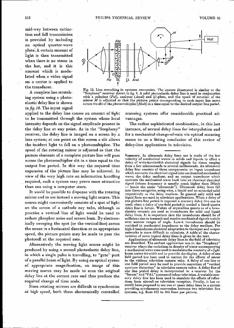
252 PHILlPS TECHNICAL REVIEW VOLUME 25
Fig. lB. Line stretching in systems conversion. The system illustrated is similar to the"Scophony" receiver shown in fig. B.A solid photoelastic delay line is used in conjunctionwith a polariser (Pal), analyser (Anal) and V.-plate, and the speed of rotation of themirror .M is adjusted so that the picture points corresponding to each input line moveacross the slit of the photomultiplier (]I,f uIt) in a time equal to the desired output line period.
mid-way between extinc-tion and full transmissionis provided by includingan optical quarter-waveplate: A certain amount oflight is then transmittedwhen there is no stress inthe bar, and it is thisamount which is modu-lated when a video signalon a carrier is applied tothe transducer.
A complete line stretch-ing system using a photo-elasticdelay line is shownin fig. lB. The input signalapplied to the delay line causes an amount of lightto be transmitted through the system whose localintensity depends on the signal amplitude present inthe delay line at any point. As in the "Scophony"receiver, the delay line is imaged on a screen by alens system; at one point on this screen a slit allowsthe incident light to fall on a photomultiplier. Thespeed of the rotating mirror is adjusted so that thepicture elements of a complete picture line will passacross the photomultiplier slit in a time equal to theoutput line period. In this way the required timeexpansion of the picture line may be achieved. Inview of the very high rate on information handlingrequired, such a system may prove more attractivethan one using a computer store.Itwould be possible to dispense with the rotating
mirror and to use instead a moving light source. Thissource might conveniently consists of a spot of lighton the screen of a cathode ray tube, although inpractice a vertical line of light would be used toreduce phosphor noise and screen burn. By electron-ically sweeping the spot (or the verticalline) acrossthe screen in a horizontal direction at an appropriatespeed, the picture points may be made to pass thephotocell at the required rate.
Alternatively the moving light source might beproduced by using a second photoelastic delay line,in which a single pulse is travelling, to "gate" partof a parallel beam oflight. By using an optical systenof appropriate magnification, an image of thismoving source may be made to' scan the originaldelay line at the correct rate and thus produce therequired change of time scale.
Since rotating mirrors are difficult to synchroniseat high speed, both these electronically controlled
oF
Pol
Abs
scanning systems offer considerable practical ad-vantages.The rather sophisticated combination, in this last
instance, of several delay lines for interpolation andfor a mechanical change-of-rate via optical scanningseems to us a fitting conclusion of this review ofdelay-line applications in television.
Summary. In ultrasonic delay lines use is made of the lowvelocity of mechanical waves in solids and liquids to effect adelay of wide-bandwidth electrical signals for times rangingfrom a few microseconds to several milliseconds. An ultrasonicdelay line consists of three components: an input transducerwhich converts the electrical signal into an identical mechanicalwave; the delay medium; and an output transducer whichconverts the mechanical wave back into an identical electricalsignal (whose frequency is usually much higher than 20kcJs- hence the name "ultrasonic"). Ultrasonic delay lines fallinto three categories, using wire, a liquid and an extended solidrespectively as the delay medium. In general only solid andliquid lines are used in television applications. When a delay ofone picture line period is required a mercury delay line can heused; when a delay of one field period is needed a fused-quartzdelay line is better. Wafers of crystalline quartz or of a ferro-electric ceramic are used as transducers for solid and liquiddelay lines. It is important that the transducers should be ofsufficient size to transmit and receive mechanical signals mainlyover narrow ranges of angle. Low-k transducers should bematched in mechanical impedance to the delay medium. Forhigh-k transducers electrical adaptation to the input and outputnetworks is more difficult to calculate. A table of the charac-teristics of some typical delay lines is given in the text.Applications of ultrasonic delay lines in the field of television
are described. The earliest application was in the "Scophony"receiver where the variations in density ofwater accompanyinga meehanical wave wereused to modulate the intensity of a lightbeam across its width and to provide the display. A delay of onefield period has been used to correct for the effects of smearin the vidicon television camera tube. A delay of one line orone field period may be used to provide correction of "verticalaperture distortion" in television camera tubes. A delay line ofone line period delay is incorporated in a receiver for the"Secam" and "PAL" systemsof colour television. Avariable mer-cury delay line has been used to simulate the effects of reflec-tions from aircraft on television reception. Finally, it has re-cently been proposed to use one or more delay lines in a systemproviding synchronous conversion between two television linesystems, e.g, from 625 to 405 lines per picture.