Embed Size (px)
Citation preview
026-1003 Rev 1 10-06-97
UltraSite User’s GuideBEC Supplement


man-s se
�����$LUSRUW�5RDG��6XLWH����.HQQHVDZ��*$������
3KRQH����������������)D[����������������
ALL RIGHTS RESERVED.
The information contained in this manual has been carefully checked and is believed to be accurate. However, Computer Process Controls, Inc. assumes no responsibility for any inaccuracies that may be contained herein. In no event will Computer Process Controls, Inc. be liable for any direct, indirect, special, incidental, or consequential damages resulting from any defect or omission in this manual, even if advised of the possibility of such damages. In the interest of continued product development, Com-puter Process Controls, Inc. reserves the right to make improvements to this manual, and the products described herein, at any time without notice or obligation.
THIS PRODUCT IS AN FCC CLASS A DIGITAL DEVICE.
This equipment has been tested and found to comply with the limits for a Class A dig-ital device, pursuant to Part 15 of the FCC Rules. These limits are designed to provide reasonable protection against harmful interference when the equipment is operated in a commercial environment. This equipment generates, uses, and can radiate radio fre-quency energy, and—if not installed and used in accordance with this instruction ual—may cause harmful interference to radio communications. Operation of thiequipment in a residential area is likely to cause harmful interference in which cacorrection of the interference will be at the user’s expense.

Table of Contents INTRODUCTION TO THE ULTRASITE BEC SUPPLEMENT.............................................................................. 1
1 DEVICE SETUP ............................................................................................................................................................ 2
1.1. MAIN MENU ................................................................................................................................................................. 21.1.1. Device Configuration............................................................................................................................................ 31.1.2. I/O Board Setup .................................................................................................................................................... 41.1.3. Device Board/Point Configuration ....................................................................................................................... 51.1.4. Communications Information ............................................................................................................................... 51.1.5. Alarm Filtering ..................................................................................................................................................... 61.1.6. System Schedule .................................................................................................................................................... 71.1.7. AHU Setup............................................................................................................................................................. 8
2 AHU............................................................................................................................................................................... 10
2.1. MAIN MENU ............................................................................................................................................................... 102.1.1. Override/Bypass Setup........................................................................................................................................ 10
2.2. INDIVIDUAL AHU MENU............................................................................................................................................ 112.2.1. AHU Status Screen.............................................................................................................................................. 122.2.2. Heat/Cool Setpoints ............................................................................................................................................ 142.2.3. Heat Stage Delays (Single Set Point Only) ......................................................................................................... 152.2.4. Cool Stage Delays (Single Set Point only).......................................................................................................... 162.2.5. Heat Stage Setpoints (Separate Set Point only) .................................................................................................. 162.2.6. Cool Stage Setpoints (Separate Set Point only) .................................................................................................. 172.2.7. Alarm Setpoints ................................................................................................................................................... 182.2.8. Load Shed Setpoints ............................................................................................................................................ 192.2.9. Output Statistics .................................................................................................................................................. 20
2.3. INDIVIDUAL AHU SETUP MENU ................................................................................................................................ 212.3.1. AHU Main Setup ................................................................................................................................................. 222.3.2. AHU Board/Point Configuration ........................................................................................................................ 242.3.3. Fan Setup ............................................................................................................................................................ 252.3.4. Two-Speed Fan Setup.......................................................................................................................................... 252.3.5. Variable-Speed Fan Setup .................................................................................................................................. 262.3.6. Load Shed Setup.................................................................................................................................................. 272.3.7. Fan Fail Alarm Bypass ....................................................................................................................................... 272.3.8. Setup Instance ..................................................................................................................................................... 28
3 ANTI-SWEAT CONTROL......................................................................................................................................... 29
3.1. MAIN MENU ............................................................................................................................................................... 293.1.1. Anti-Sweat Overrides .......................................................................................................................................... 303.1.2. Anti-Sweat Outputs Setup.................................................................................................................................... 303.1.3. Board/Point Configuration ................................................................................................................................. 313.1.4. Anti-Sweat Individual Circuits Menu.................................................................................................................. 313.1.5. Anti-Sweat Status Screen .................................................................................................................................... 323.1.6. Anti-Sweat Circuit Setpoints ............................................................................................................................... 333.1.7. Setup Instance ..................................................................................................................................................... 33
4 BOILERS...................................................................................................................................................................... 34
4.1. MAIN MENU ............................................................................................................................................................... 344.2. INDIVIDUAL BOILERS MENU ...................................................................................................................................... 35
4.2.1. Boiler Status Screen ............................................................................................................................................ 354.2.2. Boiler Setpoints ................................................................................................................................................... 36
UltraSite User’s Guide BEC Supplement Table of Contents • i
4.2.3. Boiler Setup ......................................................................................................................................................... 374.2.4. Setup Instance ..................................................................................................................................................... 37
5 DEMAND CONTROL................................................................................................................................................. 38
5.1. MAIN MENU................................................................................................................................................................ 385.2. DEMAND CONTROL CIRCUITS MENU ......................................................................................................................... 39
5.2.1. Demand Control Status ....................................................................................................................................... 405.2.2. Demand Setpoints................................................................................................................................................ 415.2.3. Alarm Setpoints ................................................................................................................................................... 425.2.4. Demand Setup ..................................................................................................................................................... 425.2.5. Setup Instance ..................................................................................................................................................... 43
6 DIMMER CONTROL ................................................................................................................................................. 44
6.1. MAIN MENU................................................................................................................................................................ 446.2. DIMMER ZONES MENU ............................................................................................................................................... 45
6.2.1. Dimmer Status ..................................................................................................................................................... 456.2.2. Dimmer Setpoints ................................................................................................................................................ 466.2.3. Dimmer Override ................................................................................................................................................ 476.2.4. Dimmer Setup...................................................................................................................................................... 476.2.5. Setup Instance ..................................................................................................................................................... 48
7 SCHEDULES................................................................................................................................................................ 49
7.1. MAIN MENU................................................................................................................................................................ 497.1.1. Light Sensor Setup............................................................................................................................................... 49
7.2. INDIVIDUAL SCHEDULES MENU.................................................................................................................................. 507.2.1. Schedule Events................................................................................................................................................... 517.2.2. Light Sensor Overrides........................................................................................................................................ 517.2.3. Schedule Proof .................................................................................................................................................... 527.2.4. Maintenance Override......................................................................................................................................... 527.2.5. Schedule Override ............................................................................................................................................... 537.2.6. Shed Parameters ................................................................................................................................................. 537.2.7. Schedule Setup..................................................................................................................................................... 547.2.8. Setup Instance ..................................................................................................................................................... 54
8 SENSOR CONTROL................................................................................................................................................... 55
8.1. MAIN MENU................................................................................................................................................................ 558.1.1. Board/Point Configuration ................................................................................................................................. 56
8.2. INDIVIDUAL SENSORS MENU ...................................................................................................................................... 568.2.1. Sensor Status ....................................................................................................................................................... 578.2.2. Output Statistics .................................................................................................................................................. 588.2.3. Setpoints .............................................................................................................................................................. 598.2.4. Alarm Setpoints ................................................................................................................................................... 608.2.5. Unoccupied Set Points ........................................................................................................................................ 618.2.6. Overrides............................................................................................................................................................. 628.2.7. Sensor Load Shed Setpoints ................................................................................................................................ 638.2.8. Sensor Setup ........................................................................................................................................................ 648.2.9. Setup Instance ..................................................................................................................................................... 64
9 ANALOG INPUT MODULES.................................................................................................................................... 65
9.1. INDIVIDUAL ANALOG INPUT MODULES MENU........................................................................................................... 659.1.1. Analog Input Module Status Screen .................................................................................................................... 669.1.2. Setpoints (Cut In/Out) ......................................................................................................................................... 679.1.3. Alarms ................................................................................................................................................................. 679.1.4. Setup (Combiner/Limiting/Filter) ....................................................................................................................... 689.1.5. Analog Inputs Input Setup ................................................................................................................................... 70
ii • Table of Contents 026-1003 Rev 1 10-06-97
9.1.6. Analog Inputs Output Setup ................................................................................................................................ 709.1.7. Counter Setup...................................................................................................................................................... 719.1.8. Setup Instance ..................................................................................................................................................... 71
10 ANALOG OUTPUT MODULES ............................................................................................................................. 72
10.1. INDIVIDUAL ANALOG OUTPUT MODULES MENU.................................................................................................... 7210.1.1. Analog Outputs Status....................................................................................................................................... 7310.1.2. Analog Outputs Setpoints (Select/Float)........................................................................................................... 7410.1.3. Analog Outputs Setup (Filter/PWM)................................................................................................................. 7510.1.4. Analog Outputs PID Setup................................................................................................................................ 7610.1.5. Analog Output Inputs Setup .............................................................................................................................. 7710.1.6. Analog Output Outputs Setup ........................................................................................................................... 7710.1.7. Sequencer Setup ................................................................................................................................................ 7810.1.8. Setup Instance ................................................................................................................................................... 79
11 DIGITAL OUTPUT MODULES ............................................................................................................................. 80
11.1. INDIVIDUAL DIGITAL OUTPUT MODULES MENU .................................................................................................... 8011.1.1. Digital Output Module Status ........................................................................................................................... 8111.1.2. Digital Output Setpoints.................................................................................................................................... 8211.1.3. Digital Outputs Setup (Combiner / Schedule)................................................................................................... 8311.1.4. Digital Output Module Inputs ........................................................................................................................... 8411.1.5. Digital Output Module Outputs ........................................................................................................................ 8411.1.6. Counter Setup.................................................................................................................................................... 8511.1.7. Setup Instance ................................................................................................................................................... 85
APPENDIX A: BEC I/O MODULE INPUT SOURCES ......................................................................................... A-1
APPENDIX B: I/O MODULE QUICK REFERENCE ............................................................................................ B-1
INDEX............................................................................................................................................................................ I-1
UltraSite User’s Guide BEC Supplement Table of Contents • iii

are and
uals,
at they ns avail-llows. If oxes for
s will be
Introduction to the UltraSite BEC SupplementThe Building Environmental Control supplement for the UltraSite User’s Guide (P/N 026-1003) provides a complete de-scription of each dialog box associated with the BEC and accessible through UltraSite version 1.3. In-depth hardwsoftware information associated with the BEC may be found in P/N 026-1103, Building Environmental Control Installation and Operation Manual. To obtain supplements for other CPC REFLECS controllers or to obtain other product mancontact Computer Process Controls, Inc. at 1-800-829-2724.
This manual describes the specific dialog boxes unique to BEC versions 4.1 and above, presented in the order thappear within specified pull-down and action menus. Each section begins with a “Screen Map” that shows the optioable within each menu. The exact manual, section, and page number to refer to for information on each option foanother manual is not specified after a reference, the reference is contained within this manual. All unique dialog beach option are shown and explained after the Screen Map.
Commands common in UltraSite, such as Add New or Print Setpoints, are not explained in this supplement; userreferred to the appropriate section in the UltraSite User’s Guide (P/N 026-1002) for more information on these options. This supplement also does not cover the basics of maneuvering within UltraSite, see UltraSite User’s Guide (P/N 026-1002) for help on operating UltraSite menus.
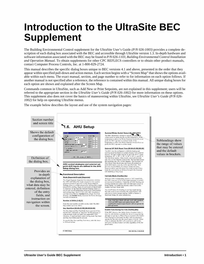
The example below describes the layout and use of the system navigation pages:
Ultrasite User’s Guide BEC Supplement Introduction • 1
1 Device Setup
1.1. Main Menu
Definition
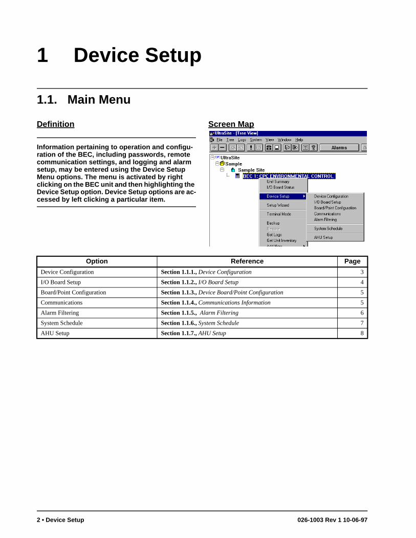
Information pertaining to operation and configu-ration of the BEC, including passwords, remote communication settings, and logging and alarm setup, may be entered using the Device Setup Menu options. The menu is activated by right clicking on the BEC unit and then highlighting the Device Setup option. Device Setup options are ac-cessed by left clicking a particular item.
Screen Map
Option Reference Page
Device Configuration Section 1.1.1., Device Configuration 3
I/O Board Setup Section 1.1.2., I/O Board Setup 4
Board/Point Configuration Section 1.1.3., Device Board/Point Configuration 5
Communications Section 1.1.4., Communications Information 5
Alarm Filtering Section 1.1.5., Alarm Filtering 6
System Schedule Section 1.1.6., System Schedule 7
AHU Setup Section 1.1.7., AHU Setup 8
2 • Device Setup 026-1003 Rev 1 10-06-97
c-as. -t
rd-i-
-y-
an-e.
e s-
es
hr- If -l-
ter f
1.1.1. Device Configuration
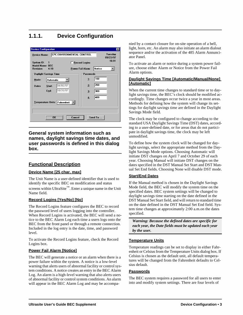
General system information such as names, daylight savings time dates, and user passwords is defined in this dialog box.
Functional Description
Device Name [25 char. max]
The Unit Name is a user-defined identifier that is used to identify the specific BEC on modification and status screens within UltraSite™. Enter a unique name in the Unit Name field.
Record Logins [Yes/No] [No]
The Record Logins feature configures the BEC to record the password level of users logging into the controller. When Record Logins is activated, the BEC will send a no-tice to the BEC Alarm Log each time a users logs onto the BEC from the front panel or through a remote connection. Included in the log entry is the date, time, and password level.
To activate the Record Logins feature, check the Record Logins box.
Power Fail Alarm [Notice]
The BEC will generate a notice or an alarm when there is a power failure within the system. A notice is a low-level warning that alerts users of abnormal facility or control sys-tem conditions. A notice creates an entry in the BEC Alarm Log. An alarm is a high-level warning that also alerts users of abnormal facility or control system conditions. An alarm will appear in the BEC Alarm Log and may be accompa-
nied by a contact closure for on-site operation of a bell, light, horn, etc. An alarm may also initiate an alarm dialout sequence and/or the activation of the 485 Alarm Annunci-ator Panel.
To activate an alarm or notice during a system power fail-ure, choose either Alarm or Notice from the Power Fail Alarm options.
Daylight Savings Time [Automatic/Manual/None] [Automatic]
When the current time changes to standard time or to day-light savings time, the BEC’s clock should be modified acordingly. Time changes occur twice a year in most areMethods for defining how the system will change its settings for daylight savings time are defined in the DaylighSavings Mode field.
The clock may be configured to change according to thestandard USA Daylight Savings Time (DST) dates, accoing to a user-defined date, or for areas that do not particpate in daylight savings time, the clock may be left unmodified.
To define how the system clock will be changed for daylight savings, select the appropriate method from the Dalight Savings Mode options. Choosing Automatic will initiate DST changes on April 7 and October 29 of eachyear. Choosing Manual will initiate DST changes on thedates specified in the DST Manual Set Start and DST Mual Set End fields. Choosing None will disable DST mod
Start/End Dates
If the Manual method is chosen in the Daylight SavingsMode field, the BEC will modify the system time on the specified dates. BEC system settings will be changed todaylight savings time starting on the date defined in theDST Manual Set Start field, and will return to standard timon the date defined in the DST Manual Set End field. Sytem time changes at approximately 2:00 a.m.on the datspecified.
Temperature Units
Temperature readings can be set to display in either Faenheit or Celsius from the Temperature Units dialog box.Celsius is chosen as the default unit, all default temperatures will be changed from the Fahrenheit defaults to Cesius default.
Passwords
The BEC system requires a password for all users to eninto and modify system settings. There are four levels o
Warning: Because the defined dates are specific for each year, the Date fields must be updated each year by the user.
Ultrasite User’s Guide BEC Supplement Device Configuration • 3
access to the BEC. A detailed description of each access level is given in Table 1-1. To change the passwords, enter the desired password in each password level field. This val-ue may be changed at any time to any six digit character
string. After a new password is defined, it may be used to log into the system at the corresponding access level.
1.1.2. I/O Board Setup
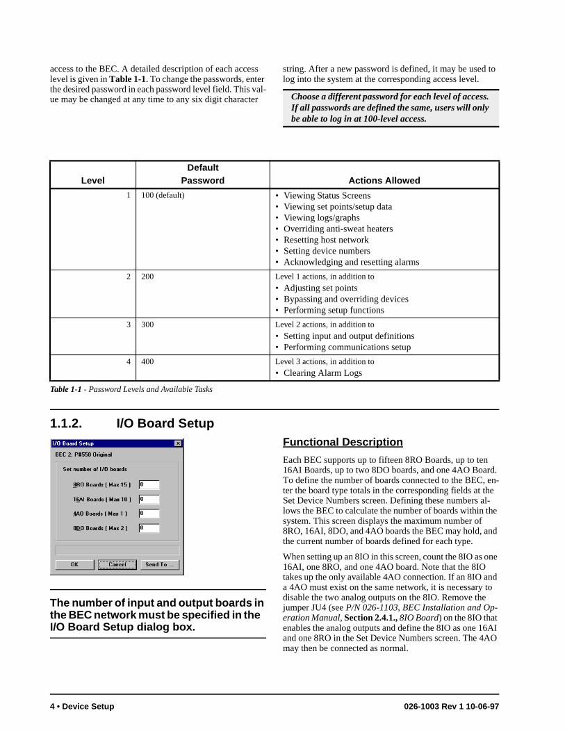
The number of input and output boards in the BEC network must be specified in the I/O Board Setup dialog box.
Functional Description
Each BEC supports up to fifteen 8RO Boards, up to ten 16AI Boards, up to two 8DO boards, and one 4AO Board. To define the number of boards connected to the BEC, en-ter the board type totals in the corresponding fields at the Set Device Numbers screen. Defining these numbers al-lows the BEC to calculate the number of boards within the system. This screen displays the maximum number of 8RO, 16AI, 8DO, and 4AO boards the BEC may hold, and the current number of boards defined for each type.
When setting up an 8IO in this screen, count the 8IO as one 16AI, one 8RO, and one 4AO board. Note that the 8IO takes up the only available 4AO connection. If an 8IO and a 4AO must exist on the same network, it is necessary to disable the two analog outputs on the 8IO. Remove the jumper JU4 (see P/N 026-1103, BEC Installation and Op-eration Manual, Section 2.4.1., 8IO Board) on the 8IO that enables the analog outputs and define the 8IO as one 16AI and one 8RO in the Set Device Numbers screen. The 4AO may then be connected as normal.
Choose a different password for each level of access. If all passwords are defined the same, users will only be able to log in at 100-level access.
LevelDefault
Password Actions Allowed
1 100 (default) • Viewing Status Screens• Viewing set points/setup data• Viewing logs/graphs• Overriding anti-sweat heaters• Resetting host network• Setting device numbers• Acknowledging and resetting alarms
2 200 Level 1 actions, in addition to
• Adjusting set points• Bypassing and overriding devices• Performing setup functions
3 300 Level 2 actions, in addition to
• Setting input and output definitions• Performing communications setup
4 400 Level 3 actions, in addition to
• Clearing Alarm Logs
Table 1-1 - Password Levels and Available Tasks
4 • Device Setup 026-1003 Rev 1 10-06-97
he -c-
the a--
.
o-
e et
1.1.3. Device Board/Point Configuration
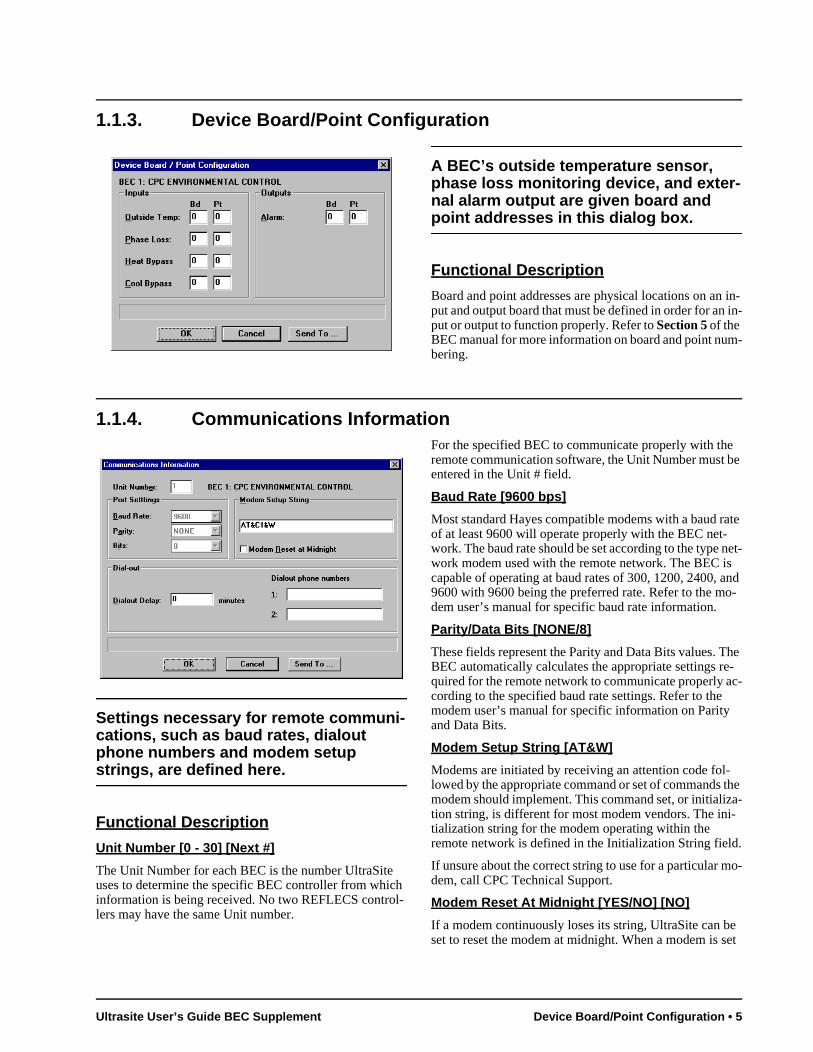
A BEC’s outside temperature sensor, phase loss monitoring device, and exter-nal alarm output are given board and point addresses in this dialog box.
Functional Description
Board and point addresses are physical locations on an in-put and output board that must be defined in order for an in-put or output to function properly. Refer to Section 5 of the BEC manual for more information on board and point num-bering.
1.1.4. Communications Information
Settings necessary for remote communi-cations, such as baud rates, dialout phone numbers and modem setup strings, are defined here.
Functional Description
Unit Number [0 - 30] [Next #]
The Unit Number for each BEC is the number UltraSite uses to determine the specific BEC controller from which information is being received. No two REFLECS control-lers may have the same Unit number.
For the specified BEC to communicate properly with the remote communication software, the Unit Number must be entered in the Unit # field.
Baud Rate [9600 bps]
Most standard Hayes compatible modems with a baud rate of at least 9600 will operate properly with the BEC net-work. The baud rate should be set according to the type net-work modem used with the remote network. The BEC is capable of operating at baud rates of 300, 1200, 2400, and 9600 with 9600 being the preferred rate. Refer to the mo-dem user’s manual for specific baud rate information.
Parity/Data Bits [NONE/8]
These fields represent the Parity and Data Bits values. TBEC automatically calculates the appropriate settings required for the remote network to communicate properly acording to the specified baud rate settings. Refer to the modem user’s manual for specific information on Parityand Data Bits.
Modem Setup String [AT&W]
Modems are initiated by receiving an attention code fol-lowed by the appropriate command or set of commands modem should implement. This command set, or initializtion string, is different for most modem vendors. The initialization string for the modem operating within the remote network is defined in the Initialization String field
If unsure about the correct string to use for a particular mdem, call CPC Technical Support.
Modem Reset At Midnight [YES/NO] [NO]
If a modem continuously loses its string, UltraSite can bset to reset the modem at midnight. When a modem is s
Ultrasite User’s Guide BEC Supplement Device Board/Point Configuration • 5
to be reset at midnight, UltraSite will automatically send the modem setup string to the modem. This keeps the mo-dem updated and communicating with UltraSite.
Dialout Delay [0 - 240 min.] [0]
Before the BEC may make an alarm dialout, it must wait for an amount of time specified in the Delay Before Dialout field. Enter a value between 0 and 240 minutes.
Phone Numbers
Phone numbers to be called when an alarm is generated are defined in the Phone Numbers fields. Phone numbers for
daytime dialouts as well as nighttime dialouts must be de-fined in these fields to activate the remote dialout function.
When an alarm is generated, and after the dialout delay, the dialout sequence begins. If the remote line is busy or there is no answer, the system will dial the first number six times, waiting five minutes before each attempt, until a connec-tion is made. If no connection is made, the system will dial the second phone number six times, waiting five minutes before each attempt. If there is still no connection, the sys-tem will generate an additional alarm in the BEC Alarm Log and cease dialout.
To define the phone numbers, enter the available phone numbers in the Phone Numbers fields.
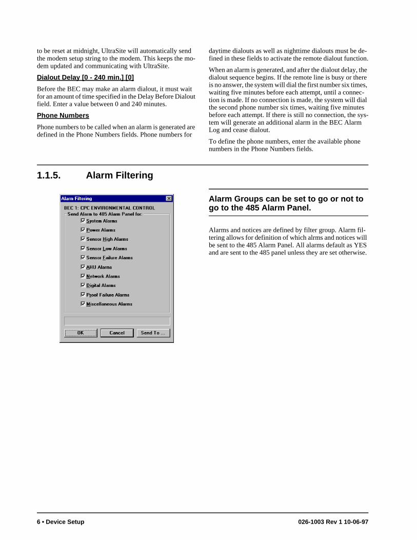
1.1.5. Alarm Filtering
Alarm Groups can be set to go or not to go to the 485 Alarm Panel.
Alarms and notices are defined by filter group. Alarm fil-tering allows for definition of which alrms and notices will be sent to the 485 Alarm Panel. All alarms default as YES and are sent to the 485 panel unless they are set otherwise.
6 • Device Setup 026-1003 Rev 1 10-06-97
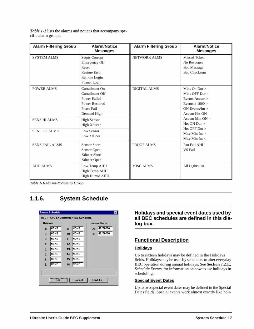
Table 1-1 lists the alarms and notices that accompany spe-cific alarm groups.
1.1.6. System Schedule
Holidays and special event dates used by all BEC schedules are defined in this dia-log box.
Functional Description
Holidays
Up to sixteen holidays may be defined in the Holidays fields. Holidays may be used by schedules to alter everyday BEC operation during annual holidays. See Section 7.2.1., Schedule Events, for information on how to use holidays in scheduling.
Special Event Dates
Up to two special event dates may be defined in the Special Dates fields. Special events work almost exactly like holi-
Alarm Filtering Group Alarm/Notice Messages
Alarm Filtering Group Alarm/Notice Messages
SYSTEM ALMS Setpts CorruptEmergency OffResetRestore ErrorRemote LoginFpanel Login
NETWORK ALMS Missed TokenNo ResponseBad MessageBad Checksum
POWER ALMS Curtailment OnCurtailment OffPower FailedPower RestoredPhase FailDemand High
DIGITAL ALMS Mins On Dur >Mins OFF Dur >Events Accum >Events x 1000 >ON Events/Int >Accum Hrs ONAccum Min ON >Hrs ON Dur >Hrs OFF Dur >Max-Min Int > Max-Min Int <
SENS HI ALMS High SensorHigh Xducer
SENS LO ALMS Low SensorLow Xducer
SENS FAIL ALMS Sensor ShortSensor OpenXducer ShortXducer Open
PROOF ALMS Fan Fail AHUVS Fail
AHU ALMS Low Temp AHUHigh Temp AHUHigh Humid AHU
MISC ALMS All Lights On
Table 1-1-Alarms/Notices by Group
Ultrasite User’s Guide BEC Supplement System Schedule • 7
nd
in
-4. ne, he
ets d
i-of
n-its
ll
r-
, ol d or n-
il-
days, except they occur only in a specified year. See Sec-tion 7.2.1., Schedule Events, for information on how to use special event dates in scheduling.
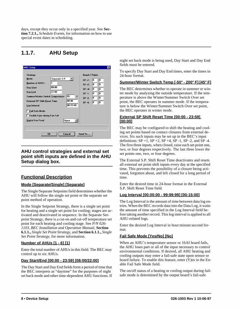
1.1.7. AHU Setup
AHU control strategies and external set point shift inputs are defined in the AHU Setup dialog box.
Functional Description
Mode [Separate/Single] [Separate]
The Single/Separate Setpoints field determines whether the AHU will follow the single set point or the separate set point method of operation.
In the Single Setpoint Strategy, there is a single set point for heating and a single set point for cooling; stages are ac-tivated and deactivated in sequence. In the Separate Set-point Strategy, there is a cut-on and cut-off temperature set point for each heating and cooling stage. See P/N 026-1103, BEC Installation and Operation Manual, Section 6.1.1., Single Set Point Strategy, and Section 6.1.1., Single Set Point Strategy, for more information.
Number of AHUs [1 - 6] [1]
Enter the total number of AHUs in this field. The BEC may control up to six AHUs.
Day Start/End [00:00 - 23:59] [08:00/22:00]
The Day Start and Day End fields form a period of time that the BEC interprets as “daytime” for the purposes of night set back mode and other time-dependent AHU functions. If
night set back mode is being used, Day Start and Day Efields must be entered.
To specify Day Start and Day End times, enter the times24-hour format.
Summer/Winter Switch Temp [-50° - 200° F] [45° F]
The BEC determines whether to operate in summer or win-ter mode by analyzing the outside temperature. If the tem-perature is above the Winter/Summer Switch Over set point, the BEC operates in summer mode. If the tempera-ture is below the Winter/Summer Switch Over set point, the BEC operates in winter mode.
External SP Shift Reset Time [00:00 - 23:59] [00:00]
The BEC may be configured to shift the heating and cool-ing set points based on contact closures from external de-vices. Six such inputs may be set up in the BEC’s inputdefinitions: SP +1, SP +2, SP +4, SP -1, SP -2, and SPThe first three inputs, when closed, raise each set point otwo, or four degrees respectively. The last three lower tset points one, two, or four degrees.
The External S.P. Shift Reset Time deactivates and resall external set point shift inputs every day at the specifietime. This prevents the possibility of a closure being actvated, forgotten about, and left closed for a long period time.
Enter the desired time in 24-hour format in the ExternalS.P. Shift Reset Time field.
Log Interval [00:00:00 - 99:99:99] [00:15:00]
The Log Interval is the amount of time between data log etries. When the BEC records data into the Data Log, it wathe amount of time specified in the Log Interval field be-fore taking another record. This log interval is applied to aAHU-related logs.
Enter the desired Log Interval in hour:minute:second fomat.
Fail Safe Mode [Yes/No] [No]
When an AHU’s temperature sensor or 16AI board failsthe AHU loses part or all of the input necessary to contrenvironmental conditions. If desired, all AHU heating ancooling outputs may enter a fail-safe state upon sensor board failure. To enable this feature, enter (Y)es in the Eable Fail Safe Mode field.
The on/off status of a heating or cooling output during fasafe mode is determined by the output board’s fail-safe
8 • Device Setup 026-1003 Rev 1 10-06-97

switch and/or jumper settings. Refer to BEC Installation and Operation Manual, Section 4.14., Fail-Safe Dip Switch Settings, for more information.
Enable Fans During Fan Fail [Yes/No] [No]
If the BEC detects a fan failure from a fan proof input, it must be told whether to disable the fan or to keep making attempts to activate it. When (N)o is selected in the Enable Fans During Fan Fail field, the BEC will not attempt to op-erate the fan when the fan proof input is FALSE. When
(Y)es is selected, the BEC will continue to call for fan ac-tivation and deactivation normally regardless of the fan proof status.
Digital Fan Proof
A fan proof checking device sends the proof status of a fan to the BEC by sending a digital signal. Depending upon the proof checking device being used, the signal that signifies a failure may be either OPEN or CLOSED. By default, an OPEN signifies a fan failure. Select the appropriate setting from the Digital Fan Proof dialog box.
Board/Points
Enter the board and point addresses for the AHU external set point shift contacts in the appropriate fields.
Note: Fail-Safe Mode will only work with standard 16AI and 8RO input and output boards. 8IO combi-nation input/output boards will not operate in fail-safe mode.
Ultrasite User’s Guide BEC Supplement AHU Setup • 9
2 AHU
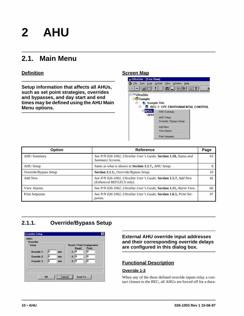
2.1. Main Menu
Definition
Setup information that affects all AHUs, such as set point strategies, overrides and bypasses, and day start and end times may be defined using the AHU Main Menu options.
Screen Map
2.1.1. Override/Bypass Setup
External AHU override input addresses and their corresponding override delays are configured in this dialog box.
Functional Description
Override 1-3
When any of the three defined override inputs relay a con-tact closure to the BEC, all AHUs are forced off for a dura-
Option Reference Page
AHU Summary See P/N 026-1002, UltraSite User’s Guide, Section 1.10, Status and Summary Screens.
63
AHU Setup Same as what is shown in Section 1.1.7., AHU Setup. 8
Override/Bypass Setup Section 2.1.1., Override/Bypass Setup. 10
Add New See P/N 026-1002, UltraSite User’s Guide, Section 1.5.7, Add New (Enhanced REFLECS only).
42
View Alarms See P/N 026-1002, UltraSite User’s Guide, Section 1.11, Alarm View. 66
Print Setpoints See P/N 026-1002, UltraSite User’s Guide, Section 1.6.1, Print Set-points.
47
10 • AHU 026-1003 Rev 1 10-06-97
tion of time equal to the override’s specified delay. Specify a delay between 0 and 240 minutes for each defined over-ride input.
Board/Point Configuration
Enter the board and point addresses for overrides 1-3 inthese fields.
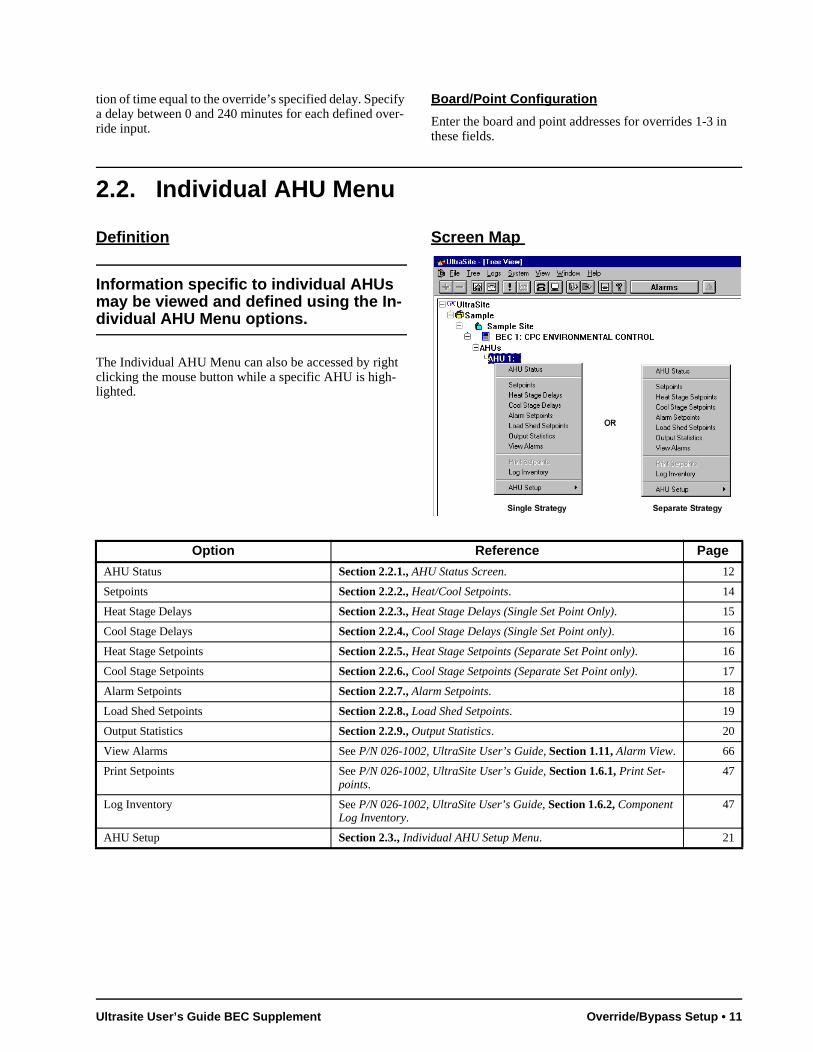
2.2. Individual AHU Menu
Definition
Information specific to individual AHUs may be viewed and defined using the In-dividual AHU Menu options.
The Individual AHU Menu can also be accessed by right clicking the mouse button while a specific AHU is high-lighted.
Screen Map
Option Reference Page
AHU Status Section 2.2.1., AHU Status Screen. 12
Setpoints Section 2.2.2., Heat/Cool Setpoints. 14
Heat Stage Delays Section 2.2.3., Heat Stage Delays (Single Set Point Only). 15
Cool Stage Delays Section 2.2.4., Cool Stage Delays (Single Set Point only). 16
Heat Stage Setpoints Section 2.2.5., Heat Stage Setpoints (Separate Set Point only). 16
Cool Stage Setpoints Section 2.2.6., Cool Stage Setpoints (Separate Set Point only). 17
Alarm Setpoints Section 2.2.7., Alarm Setpoints. 18
Load Shed Setpoints Section 2.2.8., Load Shed Setpoints. 19
Output Statistics Section 2.2.9., Output Statistics. 20
View Alarms See P/N 026-1002, UltraSite User’s Guide, Section 1.11, Alarm View. 66
Print Setpoints See P/N 026-1002, UltraSite User’s Guide, Section 1.6.1, Print Set-points.
47
Log Inventory See P/N 026-1002, UltraSite User’s Guide, Section 1.6.2, Component Log Inventory.
47
AHU Setup Section 2.3., Individual AHU Setup Menu. 21
Ultrasite User’s Guide BEC Supplement Override/Bypass Setup • 11
ill on
ed d U
i-p
t d to
an m
di- is
g 2
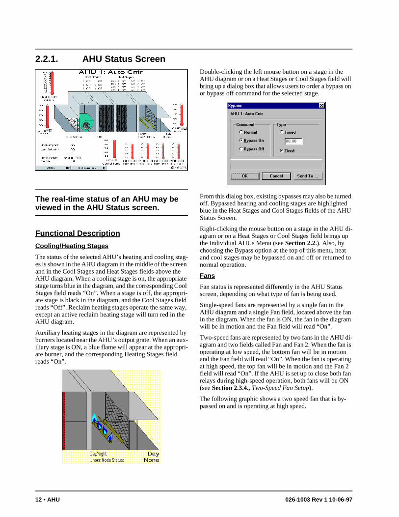
2.2.1. AHU Status Screen
The real-time status of an AHU may be viewed in the AHU Status screen.
Functional Description
Cooling/Heating Stages
The status of the selected AHU’s heating and cooling stag-es is shown in the AHU diagram in the middle of the screen and in the Cool Stages and Heat Stages fields above the AHU diagram. When a cooling stage is on, the appropriate stage turns blue in the diagram, and the corresponding Cool Stages field reads “On”. When a stage is off, the appropri-ate stage is black in the diagram, and the Cool Stages field reads “Off”. Reclaim heating stages operate the same way, except an active reclaim heating stage will turn red in the AHU diagram.
Auxiliary heating stages in the diagram are represented by burners located near the AHU’s output grate. When an aux-iliary stage is ON, a blue flame will appear at the appropri-ate burner, and the corresponding Heating Stages field reads “On”.
Double-clicking the left mouse button on a stage in the AHU diagram or on a Heat Stages or Cool Stages field wbring up a dialog box that allows users to order a bypassor bypass off command for the selected stage.
From this dialog box, existing bypasses may also be turnoff. Bypassed heating and cooling stages are highlighteblue in the Heat Stages and Cool Stages fields of the AHStatus Screen.
Right-clicking the mouse button on a stage in the AHU dagram or on a Heat Stages or Cool Stages field brings uthe Individual AHUs Menu (see Section 2.2.). Also, by choosing the Bypass option at the top of this menu, heaand cool stages may be bypassed on and off or returnenormal operation.
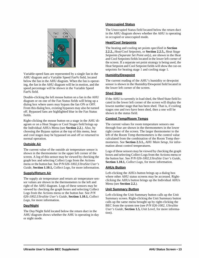
Fans
Fan status is represented differently in the AHU Status screen, depending on what type of fan is being used.
Single-speed fans are represented by a single fan in theAHU diagram and a single Fan field, located above the fin the diagram. When the fan is ON, the fan in the diagrawill be in motion and the Fan field will read “On”.
Two-speed fans are represented by two fans in the AHUagram and two fields called Fan and Fan 2. When the fanoperating at low speed, the bottom fan will be in motionand the Fan field will read “On”. When the fan is operatinat high speed, the top fan will be in motion and the Fan field will read “On”. If the AHU is set up to close both fanrelays during high-speed operation, both fans will be ON(see Section 2.3.4., Two-Speed Fan Setup).
The following graphic shows a two speed fan that is by-passed on and is operating at high speed.
12 • AHU 026-1003 Rev 1 10-06-97
n
o-e ing
r e e r-
aph or
Variable-speed fans are represented by a single fan in the AHU diagram and a Variable Speed Fan% field, located below the fan in the AHU diagram. When the fan is operat-ing, the fan in the AHU diagram will be in motion, and the speed percentage will be shown in the Variable Speed Fan% field.
Double-clicking the left mouse button on a fan in the AHU diagram or on one of the Fan Status fields will bring up a dialog box where users may bypass the fan ON or OFF. From this dialog box, existing bypasses may also be turned off. Bypassed fans are highlighted blue in the Fan Status fields.
Right-clicking the mouse button on a stage in the AHU di-agram or on a Heat Stages or Cool Stages field brings up the Individual AHUs Menu (see Section 2.2.). Also, by choosing the Bypass option at the top of this menu, heat and cool stages may be bypassed on and off or returned to normal operation.
Outside Air
The current value of the outside air temperature sensor is shown in the thermometer in the upper left corner of the screen. A log of this sensor may be viewed by checking the graph box and selecting Collect Logs from the Actions menu or the button bar. See P/N 026-1002,UltraSite User’s Guide, Section 1.10.1, Collect Logs, for more information.
Supply/Return Air
The supply air temperature and return air temperature sen-sor values are shown in the thermometers to the left and right of the AHU diagram. Logs of these sensors may be viewed by checking the graph boxes and selecting Collect Logs from the Actions menu or the button bar. See P/N 026-1002,UltraSite User’s Guide, Section 1.10.1, Collect Logs, for more information.
Day/Night
The Day/Night field located below the return duct in the AHU diagram shows whether the AHU is operating in day or night mode.
Unoccupied Status
The Unoccupied Status field located below the return duct in the AHU diagram shows whether the AHU is operating in occupied or unoccupied mode.
Heat/Cool Setpoints
The heating and cooling set points specified in Section 2.2.2., Heat/Cool Setpoints, or Section 2.2.5., Heat Stage Setpoints (Separate Set Point only), are shown in the Heat and Cool Setpoints fields located in the lower left corner of the screen. If a separate set point strategy is being used, the Heat Setpoint and Cool Setpoint fields will show the cut-on setpoints for heating stage 1 and cooling stage 1.
Humidity/Dewpoint
The current reading of the AHU’s humidity or dewpoint sensor is shown in the Humidity/Dewpoint field located ithe lower left corner of the screen.
Shed State
If the AHU is currently in load shed, the Shed State field lcated in the lower left corner of the screen will display thlowest number stage that has been shed. That is, if coolstages one and two have been shed, then a one will beshown in the status field.
Control Temp/Room Temps
The current values for room temperature sensors one through four are shown in the thermometers in the loweright corner of the screen. The larger thermometer to thleft of the Room Temp thermometers is the control valucalculated from the combination of the Room Temp themometers. See Section 2.3.1., AHU Main Setup, for infor-mation about control temperatures.
Logs of these sensors may be viewed by checking the grboxes and selecting Collect Logs from the Actions menuthe button bar. See P/N 026-1002,UltraSite User’s Guide, Section 1.10.1, Collect Logs, for more information.
AHUs Button
Left-clicking the AHUs button brings up a dialog box where other AHU status screens may be accessed. Right-clicking the AHUs button brings up the Individual AHUs Menu (see Section 2.2.).
Unit Summary Button
Left-clicking the Unit Summary button calls up the Unit Summary screen. Right-clicking the Unit Summary button calls up the same menu brought up by right-clicking the BEC from the system tree (see P/N 026-1002, UltraSite User’s Guide, Section 1.5, Unit Level, for more informa-tion).
Ultrasite User’s Guide BEC Supplement AHU Status Screen • 13
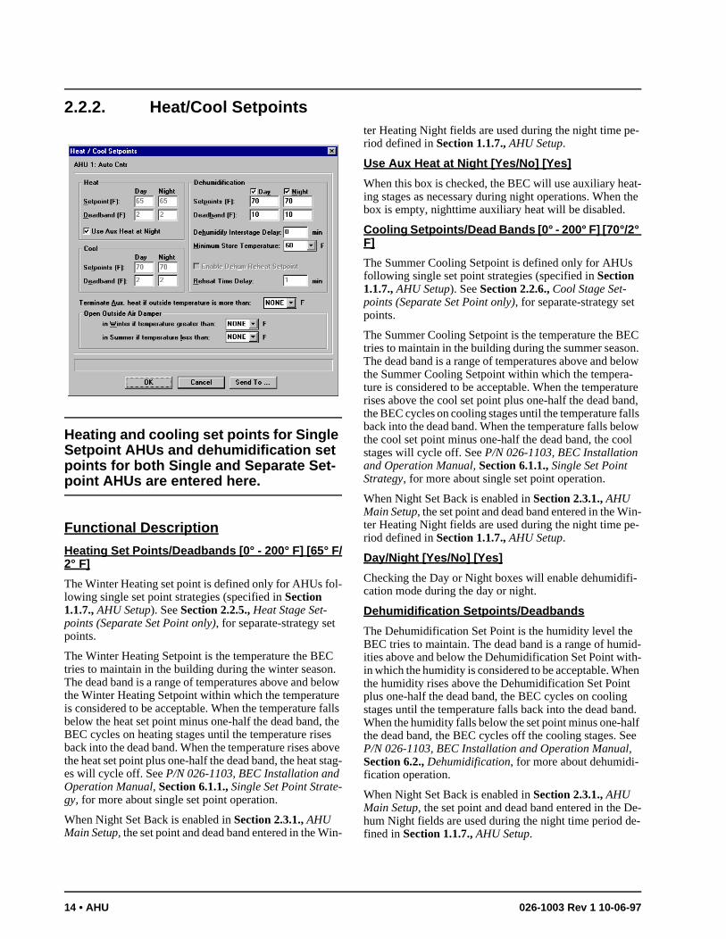
2.2.2. Heat/Cool Setpoints
Heating and cooling set points for Single Setpoint AHUs and dehumidification set points for both Single and Separate Set-point AHUs are entered here.
Functional Description
Heating Set Points/Deadbands [0° - 200° F] [65° F/2° F]
The Winter Heating set point is defined only for AHUs fol-lowing single set point strategies (specified in Section 1.1.7., AHU Setup). See Section 2.2.5., Heat Stage Set-points (Separate Set Point only), for separate-strategy set points.
The Winter Heating Setpoint is the temperature the BEC tries to maintain in the building during the winter season. The dead band is a range of temperatures above and below the Winter Heating Setpoint within which the temperature is considered to be acceptable. When the temperature falls below the heat set point minus one-half the dead band, the BEC cycles on heating stages until the temperature rises back into the dead band. When the temperature rises above the heat set point plus one-half the dead band, the heat stag-es will cycle off. See P/N 026-1103, BEC Installation and Operation Manual, Section 6.1.1., Single Set Point Strate-gy, for more about single set point operation.
When Night Set Back is enabled in Section 2.3.1., AHU Main Setup, the set point and dead band entered in the Win-
ter Heating Night fields are used during the night time pe-riod defined in Section 1.1.7., AHU Setup.
Use Aux Heat at Night [Yes/No] [Yes]
When this box is checked, the BEC will use auxiliary heat-ing stages as necessary during night operations. When the box is empty, nighttime auxiliary heat will be disabled.
Cooling Setpoints/Dead Bands [0° - 200° F] [70°/2° F]
The Summer Cooling Setpoint is defined only for AHUs following single set point strategies (specified in Section 1.1.7., AHU Setup). See Section 2.2.6., Cool Stage Set-points (Separate Set Point only), for separate-strategy set points.
The Summer Cooling Setpoint is the temperature the BEC tries to maintain in the building during the summer season. The dead band is a range of temperatures above and below the Summer Cooling Setpoint within which the tempera-ture is considered to be acceptable. When the temperature rises above the cool set point plus one-half the dead band, the BEC cycles on cooling stages until the temperature falls back into the dead band. When the temperature falls below the cool set point minus one-half the dead band, the cool stages will cycle off. See P/N 026-1103, BEC Installation and Operation Manual, Section 6.1.1., Single Set Point Strategy, for more about single set point operation.
When Night Set Back is enabled in Section 2.3.1., AHU Main Setup, the set point and dead band entered in the Win-ter Heating Night fields are used during the night time pe-riod defined in Section 1.1.7., AHU Setup.
Day/Night [Yes/No] [Yes]
Checking the Day or Night boxes will enable dehumidifi-cation mode during the day or night.
Dehumidification Setpoints/Deadbands
The Dehumidification Set Point is the humidity level the BEC tries to maintain. The dead band is a range of humid-ities above and below the Dehumidification Set Point with-in which the humidity is considered to be acceptable. When the humidity rises above the Dehumidification Set Point plus one-half the dead band, the BEC cycles on cooling stages until the temperature falls back into the dead band. When the humidity falls below the set point minus one-half the dead band, the BEC cycles off the cooling stages. See P/N 026-1103, BEC Installation and Operation Manual, Section 6.2., Dehumidification, for more about dehumidi-fication operation.
When Night Set Back is enabled in Section 2.3.1., AHU Main Setup, the set point and dead band entered in the De-hum Night fields are used during the night time period de-fined in Section 1.1.7., AHU Setup.
14 • AHU 026-1003 Rev 1 10-06-97
Dehumidify Interstage Delay [0 - 240 min.] [0 min.]
When in dehumidification mode, the BEC activates and de-activates cool stages one at a time. The delay between stage activations and deactivations (in minutes) is specified in this field. Enter a value between 0 and 240 minutes.
Minimum Store Temperature [-50° - 100° F] [60° F]
Activating cooling stages during dehumidification may have a secondary effect: lower building temperature. The Minimum Store Temperature set point prevents the tem-perature from dropping too low during dehumidification. If the building temperature falls below the Minimum Store Temperature set point, dehumidification is locked out.
Enable Dehum Reheat Setpt [Yes/No] [No]
The Enable Dehumidification Reheat Set Point feature pro-vides users with a method of keeping heating and cooling stages in single-setpoint AHUs from working against each other during dehumidification. See P/N 026-1103, BEC In-stallation and Operation Manual, Section 6.2.2., Dehu-midification Reheat Set Point, for more information.
Dehum Reheat Time Delay [0 - 240 min.] [1 min.]
When the Enable Dehumidification Reheat Set Point box is checked, the Dehum Reheat Time Delay is the number of
minutes the BEC will wait before activating all reclaim heat stages. See P/N 026-1103, BEC Installation and Op-eration Manual, Section 6.2.2., Dehumidification Reheat Set Point, for more.
Term. Aux. Heat [-50° - 99° F] [NONE]
Specifying a temperature value in this field will disable use of auxiliary heating stages when the outside ambient tem-perature sensor reads a value higher than the set point. En-tering None in this field disables this function.
Open Outside Air Damper [-50° - 99° F] [NONE]
The BEC is capable of controlling outside air dampers based on ambient temperature sensor readings. During the winter season, the outside air damper uses the set point en-tered in the During Heat Season field; when the outside air temperature is higher than the set point, the air damper will open. During the summer season, the outside air damper uses the set point entered in the During Cool Season field; when the outside air temperature is lower than the set point, the air damper will open.
To use air damper control, specify temperature values in the Outside Air Damper fields. Enter None if no air damper control is necessary.
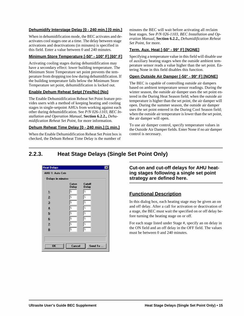
2.2.3. Heat Stage Delays (Single Set Point Only)
Cut-on and cut-off delays for AHU heat-ing stages following a single set point strategy are defined here.
Functional Description
In this dialog box, each heating stage may be given an on and off delay. After a call for activation or deactivation of a stage, the BEC must wait the specified on or off delay be-fore turning the heating stage on or off.
For each stage listed under Stage #, specify an on delay in the ON field and an off delay in the OFF field. The values must be between 0 and 240 minutes.
Ultrasite User’s Guide BEC Supplement Heat Stage Delays (Single Set Point Only) • 15
ed. d than
d. e on
vat-d than
e
acti-he
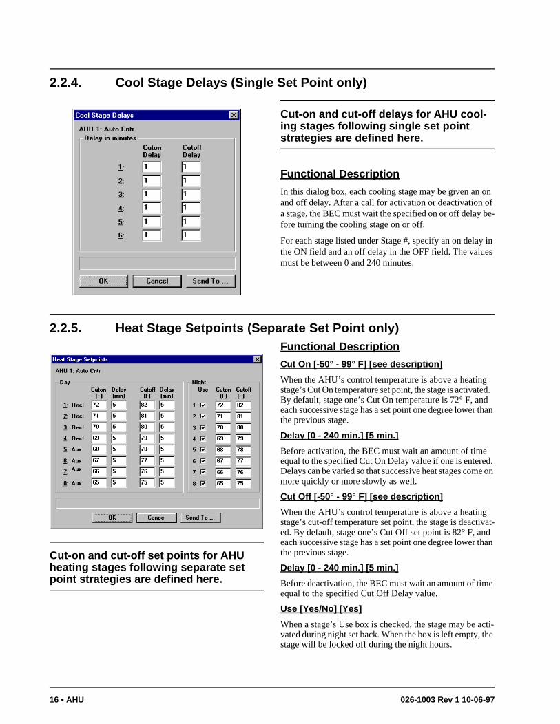
2.2.4. Cool Stage Delays (Single Set Point only)
Cut-on and cut-off delays for AHU cool-ing stages following single set point strategies are defined here.
Functional Description
In this dialog box, each cooling stage may be given an on and off delay. After a call for activation or deactivation of a stage, the BEC must wait the specified on or off delay be-fore turning the cooling stage on or off.
For each stage listed under Stage #, specify an on delay in the ON field and an off delay in the OFF field. The values must be between 0 and 240 minutes.
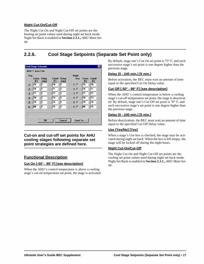
2.2.5. Heat Stage Setpoints (Separate Set Point only)
Cut-on and cut-off set points for AHU heating stages following separate set point strategies are defined here.
Functional Description
Cut On [-50° - 99° F] [see description]
When the AHU’s control temperature is above a heatingstage’s Cut On temperature set point, the stage is activatBy default, stage one’s Cut On temperature is 72° F, aneach successive stage has a set point one degree lowerthe previous stage.
Delay [0 - 240 min.] [5 min.]
Before activation, the BEC must wait an amount of timeequal to the specified Cut On Delay value if one is entereDelays can be varied so that successive heat stages commore quickly or more slowly as well.
Cut Off [-50° - 99° F] [see description]
When the AHU’s control temperature is above a heatingstage’s cut-off temperature set point, the stage is deactied. By default, stage one’s Cut Off set point is 82° F, aneach successive stage has a set point one degree lowerthe previous stage.
Delay [0 - 240 min.] [5 min.]
Before deactivation, the BEC must wait an amount of timequal to the specified Cut Off Delay value.
Use [Yes/No] [Yes]
When a stage’s Use box is checked, the stage may be vated during night set back. When the box is left empty, tstage will be locked off during the night hours.
16 • AHU 026-1003 Rev 1 10-06-97
ch he
vat-d than
e
acti-he
e.
Night Cut-On/Cut-Off
The Night Cut-On and Night Cut-Off set points are the heating set point values used during night set back mode. Night Set Back is enabled in Section 2.3.1., AHU Main Set-up.
2.2.6. Cool Stage Setpoints (Separate Set Point only)
Cut-on and cut-off set points for AHU cooling stages following separate set point strategies are defined here.
Functional Description
Cut On [-50° - 99° F] [see description]
When the AHU’s control temperature is above a cooling stage’s cut-on temperature set point, the stage is activated.
By default, stage one’s Cut On set point is 75° F, and easuccessive stage’s set point is one degree higher than tprevious stage.
Delay [0 - 240 min.] [5 min.]
Before activation, the BEC must wait an amount of timeequal to the specified Cut On Delay value.
Cut Off [-50° - 99° F] [see description]
When the AHU’s control temperature is below a coolingstage’s cut-off temperature set point, the stage is deactied. By default, stage one’s Cut Off set point is 70° F, aneach successive stage’s set point is one degree higher the previous stage.
Delay [0 - 240 min.] [5 min.]
Before deactivation, the BEC must wait an amount of timequal to the specified Cut Off Delay value.
Use [Yes/No] [Yes]
When a stage’s Use box is checked, the stage may be vated during night set back. When the box is left empty, tstage will be locked off during the night hours.
Night Cut-On/Cut-Off
The Night Cut-On and Night Cut-Off set points are the cooling set point values used during night set back modNight Set Back is enabled in Section 2.3.1., AHU Main Set-up.
Ultrasite User’s Guide BEC Supplement Cool Stage Setpoints (Separate Set Point only) • 17
th-
n-
ce no-
e--
pe sor.
om
nt n
e r-
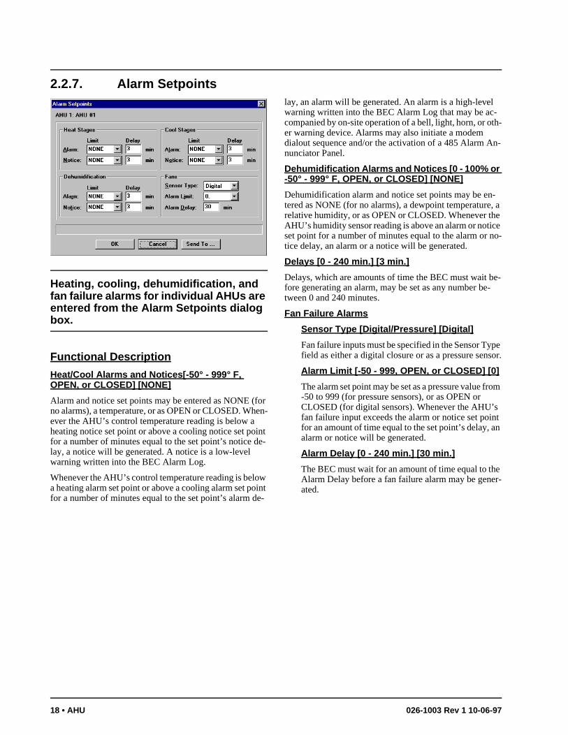
2.2.7. Alarm Setpoints
Heating, cooling, dehumidification, and fan failure alarms for individual AHUs are entered from the Alarm Setpoints dialog box.
Functional Description
Heat/Cool Alarms and Notices[-50° - 999° F, OPEN, or CLOSED] [NONE]
Alarm and notice set points may be entered as NONE (for no alarms), a temperature, or as OPEN or CLOSED. When-ever the AHU’s control temperature reading is below a heating notice set point or above a cooling notice set point for a number of minutes equal to the set point’s notice de-lay, a notice will be generated. A notice is a low-level warning written into the BEC Alarm Log.
Whenever the AHU’s control temperature reading is below a heating alarm set point or above a cooling alarm set point for a number of minutes equal to the set point’s alarm de-
lay, an alarm will be generated. An alarm is a high-levelwarning written into the BEC Alarm Log that may be ac-companied by on-site operation of a bell, light, horn, or oer warning device. Alarms may also initiate a modem dialout sequence and/or the activation of a 485 Alarm Anunciator Panel.
Dehumidification Alarms and Notices [0 - 100% or -50° - 999° F, OPEN, or CLOSED] [NONE]
Dehumidification alarm and notice set points may be en-tered as NONE (for no alarms), a dewpoint temperature, a relative humidity, or as OPEN or CLOSED. Whenever the AHU’s humidity sensor reading is above an alarm or notiset point for a number of minutes equal to the alarm or tice delay, an alarm or a notice will be generated.
Delays [0 - 240 min.] [3 min.]
Delays, which are amounts of time the BEC must wait bfore generating an alarm, may be set as any number between 0 and 240 minutes.
Fan Failure Alarms
Sensor Type [Digital/Pressure] [Digital]
Fan failure inputs must be specified in the Sensor Tyfield as either a digital closure or as a pressure sen
Alarm Limit [-50 - 999, OPEN, or CLOSED] [0]
The alarm set point may be set as a pressure value fr-50 to 999 (for pressure sensors), or as OPEN or CLOSED (for digital sensors). Whenever the AHU’sfan failure input exceeds the alarm or notice set poifor an amount of time equal to the set point’s delay, aalarm or notice will be generated.
Alarm Delay [0 - 240 min.] [30 min.]
The BEC must wait for an amount of time equal to thAlarm Delay before a fan failure alarm may be geneated.
18 • AHU 026-1003 Rev 1 10-06-97
2.2.8. Load Shed Setpoints
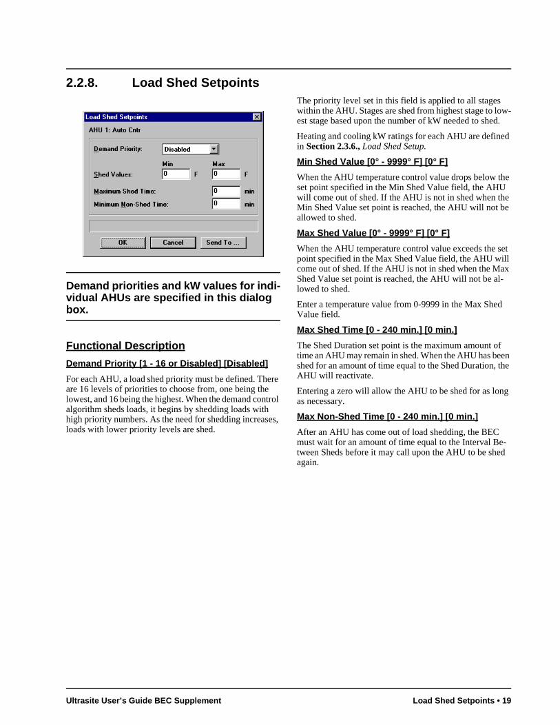
Demand priorities and kW values for indi-vidual AHUs are specified in this dialog box.
Functional Description
Demand Priority [1 - 16 or Disabled] [Disabled]
For each AHU, a load shed priority must be defined. There are 16 levels of priorities to choose from, one being the lowest, and 16 being the highest. When the demand control algorithm sheds loads, it begins by shedding loads with high priority numbers. As the need for shedding increases, loads with lower priority levels are shed.
The priority level set in this field is applied to all stages within the AHU. Stages are shed from highest stage to low-est stage based upon the number of kW needed to shed.
Heating and cooling kW ratings for each AHU are defined in Section 2.3.6., Load Shed Setup.
Min Shed Value [0° - 9999° F] [0° F]
When the AHU temperature control value drops below the set point specified in the Min Shed Value field, the AHU will come out of shed. If the AHU is not in shed when the Min Shed Value set point is reached, the AHU will not be allowed to shed.
Max Shed Value [0° - 9999° F] [0° F]
When the AHU temperature control value exceeds the set point specified in the Max Shed Value field, the AHU will come out of shed. If the AHU is not in shed when the Max Shed Value set point is reached, the AHU will not be al-lowed to shed.
Enter a temperature value from 0-9999 in the Max Shed Value field.
Max Shed Time [0 - 240 min.] [0 min.]
The Shed Duration set point is the maximum amount of time an AHU may remain in shed. When the AHU has been shed for an amount of time equal to the Shed Duration, the AHU will reactivate.
Entering a zero will allow the AHU to be shed for as long as necessary.
Max Non-Shed Time [0 - 240 min.] [0 min.]
After an AHU has come out of load shedding, the BEC must wait for an amount of time equal to the Interval Be-tween Sheds before it may call upon the AHU to be shed again.
Ultrasite User’s Guide BEC Supplement Load Shed Setpoints • 19
2.2.9. Output Statistics
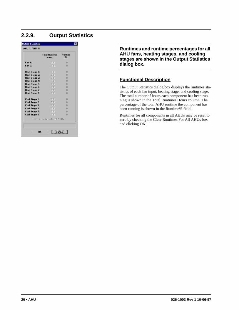
Runtimes and runtime percentages for all AHU fans, heating stages, and cooling stages are shown in the Output Statistics dialog box.
Functional Description
The Output Statistics dialog box displays the runtimes sta-tistics of each fan input, heating stage, and cooling stage. The total number of hours each component has been run-ning is shown in the Total Runtimes Hours column. The percentage of the total AHU runtime the component has been running is shown in the Runtime% field.
Runtimes for all components in all AHUs may be reset to zero by checking the Clear Runtimes For All AHUs box and clicking OK.
20 • AHU 026-1003 Rev 1 10-06-97
2.3. Individual AHU Setup Menu
Screen Map
Definition
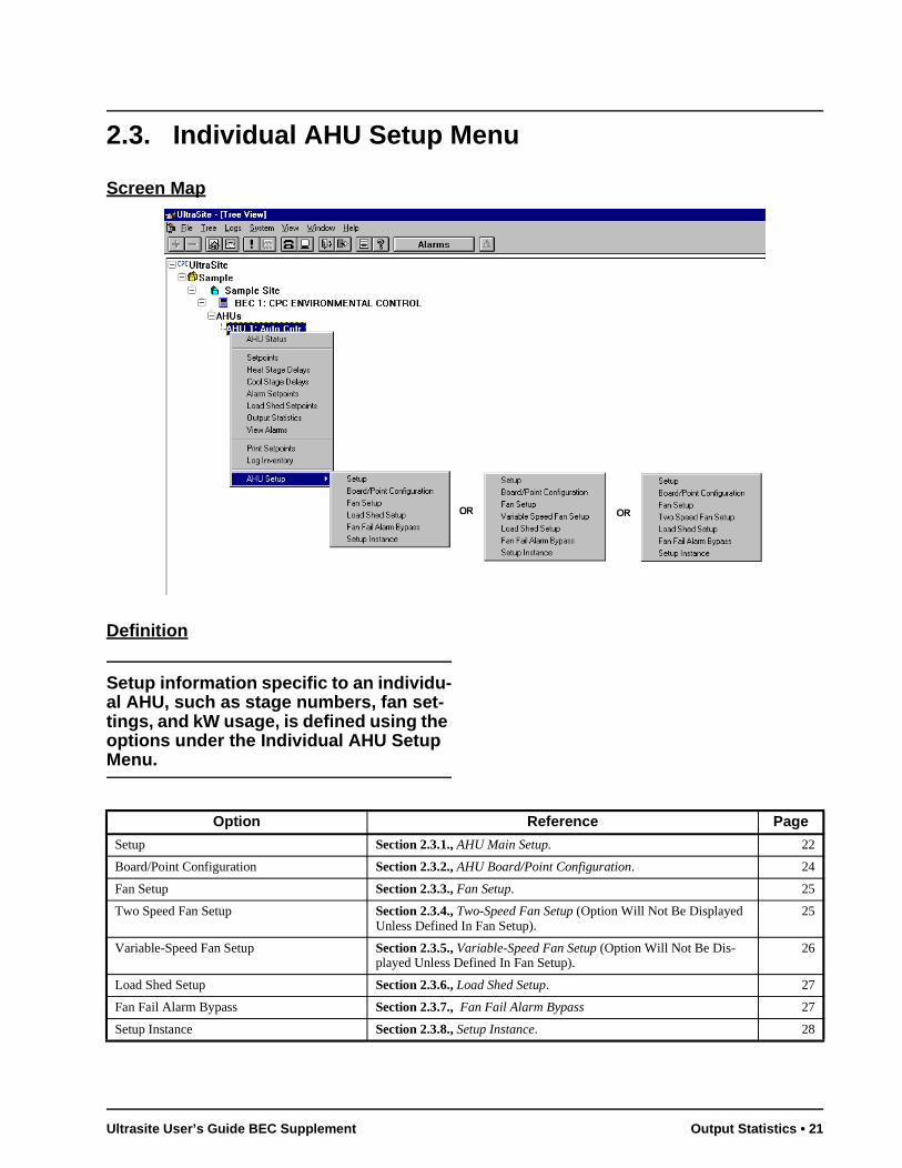
Setup information specific to an individu-al AHU, such as stage numbers, fan set-tings, and kW usage, is defined using the options under the Individual AHU Setup Menu.
Option Reference Page
Setup Section 2.3.1., AHU Main Setup. 22
Board/Point Configuration Section 2.3.2., AHU Board/Point Configuration. 24
Fan Setup Section 2.3.3., Fan Setup. 25
Two Speed Fan Setup Section 2.3.4., Two-Speed Fan Setup (Option Will Not Be Displayed Unless Defined In Fan Setup).
25
Variable-Speed Fan Setup Section 2.3.5., Variable-Speed Fan Setup (Option Will Not Be Dis-played Unless Defined In Fan Setup).
26
Load Shed Setup Section 2.3.6., Load Shed Setup. 27
Fan Fail Alarm Bypass Section 2.3.7., Fan Fail Alarm Bypass 27
Setup Instance Section 2.3.8., Setup Instance. 28
Ultrasite User’s Guide BEC Supplement Output Statistics • 21
a- to
.
t
ors ust a
ol-bi-
he
2.3.1. AHU Main Setup
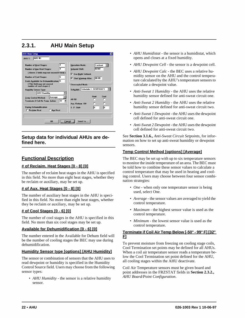
Setup data for individual AHUs are de-fined here.
Functional Description
# of Reclaim. Heat Stages [0 - 8] [0]
The number of reclaim heat stages in the AHU is specified in this field. No more than eight heat stages, whether they be reclaim or auxiliary, may be set up.
# of Aux. Heat Stages [0 - 8] [0]
The number of auxiliary heat stages in the AHU is speci-fied in this field. No more than eight heat stages, whether they be reclaim or auxiliary, may be set up.
# of Cool Stages [0 - 6] [0]
The number of cool stages in the AHU is specified in this field. No more than six cool stages may be set up.
Available for Dehumidification [0 - 6] [0]
The number entered in the Available for Dehum field will be the number of cooling stages the BEC may use during dehumidification.
Humidity Sensor type [options] [AHU Humidity]
The sensor or combination of sensors that the AHU uses to read dewpoint or humidity is specified in the Humidity Control Source field. Users may choose from the following sensor types:
• AHU Humidity - the sensor is a relative humidity sensor.
• AHU Humidistat - the sensor is a humidistat, whichopens and closes at a fixed humidity.
• AHU Dewpoint Cell - the sensor is a dewpoint cell.
• AHU Dewpoint Calc - the BEC uses a relative hu-midity sensor on the AHU and the control temperture calculated by the AHU’s temperature sensorscalculate a dewpoint value.
• Anti-Sweat 1 Humidity - the AHU uses the relative humidity sensor defined for anti-sweat circuit one
• Anti-Sweat 2 Humidity - the AHU uses the relative humidity sensor defined for anti-sweat circuit two.
• Anti-Sweat 1 Dewpoint - the AHU uses the dewpointcell defined for anti-sweat circuit one.
• Anti-Sweat 2 Dewpoint - the AHU uses the dewpointcell defined for anti-sweat circuit two.
See Section 3.1.6., Anti-Sweat Circuit Setpoints, for infor-mation on how to set up anti-sweat humidity or dewpoinsensors.
Temp Control Method [options] [Average]
The BEC may be set up with up to six temperature sensto monitor the inside temperature of an area. The BEC mbe told how to combine these sensor values to calculatecontrol temperature that may be used in heating and coing control. Users may choose between four sensor comnation strategies:
• One - when only one temperature sensor is beingused, select One.
• Average - the sensor values are averaged to yield tcontrol temperature.
• Maximum - the highest sensor value is used as thecontrol temperature.
• Minimum - the lowest sensor value is used as the control temperature.
Terminate if Coil Air Temp Below [-50° - 99° F] [32° F]
To prevent moisture from freezing on cooling stage coils, Cool Termination set points may be defined for all AHUs. When a coil air temperature sensor reads a temperature be-low the Cool Termination set point defined for the AHU, all cooling stages within the AHU deactivate.
Coil Air Temperature sensors must be given board and point addresses in the FRZSTAT fields in Section 2.3.2., AHU Board/Point Configuration.
22 • AHU 026-1003 Rev 1 10-06-97
-ck s, y-
p
ild-e-U FF . .
oc-
oc-
ng
-
Reclaim Heat During Dehum[Yes/No] [No]
By checking the Reclaim Heat During Dehum box, users may lock out the use of reclaim heating stages during dehu-midification.
Auxiliary Heat During Dehum[Yes/No] [No]
By checking the Auxiliary Heat During Dehum box, users may lock out the use of auxiliary heating stages during de-humidification.
Operation Mode [options] [Lockout]
The Mode of Operation field determines how the BEC will react to detected changes in seasons. Users may select ei-ther of two different options:
• Seasonal Lockout - during winter-like conditions, cooling mode is locked out; during summer-like conditions, heating mode is locked out.
• Auto - regardless of seasonal conditions, the BEC will activate heating during summer and cooling during winter as necessary. Heating and cooling set points may be shifted
The BEC determines summer and winter by comparing the outside temperature to the Winter/Summer Switch Over set point defined in Section 1.1.7., AHU Setup.
Seasonal Setpoints Shift [-20° - 20°] [0°]
If Auto is selected under the Mode of Operation field, a set point shift value from -20° to +20° may be entered in the Seasonal Setpoints Shift field. When the BEC operates in Winter mode, the value specified in the Seasonal Setpoints Shift is subtracted from both the heating and cooling set points. Therefore, if lower set points are desired, enter a positive value, and vice-versa.
Use Night Set Back [Yes/No] [Yes]
When the Use Night Set Back box is checked, different heating and cooling set points may be used for day and night operation. Leaving the box unchecked will cause the BEC to use normal day settings during night operation.
Start Warm Up After [Yes/No] [Yes]
In normal night set back operations, the BEC’s heating and cooling set points are shifted down when Night Set Back mode begins and returned to normal when Night Set Back ends. When the Warm Up feature is being used, rather than
switching immediately from night set points to day set points, the BEC will gradually increment the building temperature set points during the final hours of Night Set Bamode. As a result, when night set back mode terminatethe building temperature will be closer to the desired datime temperature.
To enable the Warm Up feature, check the Use Warm Ubox and enter a start time from 00:00 to 23:59.
Unoccupied Mode Schedule # [options] [Sch. 1]
The BEC uses schedules to determine what times the buing will be unoccupied. When the schedule number is dfined in the Use Schedule Number field, the selected AHwill operate in unoccupied mode when the schedule is Oand operate in occupied mode when the schedule is ONSee Section 7 for information on how to define schedules
Heat All Off [Yes/No] [No]
Checking this box bypasses all heat stages off during uncupied mode.
Cool All Off [Yes/No] [No]
Checking this box bypasses all cool stages off during uncupied mode.
Heat Aux Off [Yes/No] [No]
Checking this box disables all auxiliary heat stages duriunoccupied mode.
Dehum Off [Yes/No] [No]
Checking this box prevents the AHU from entering dehumidification mode during unoccupied hours.
Heat Set Point Shift [-50° - 99°] [0°]
If desired, the heating set point(s) defined in Section 2.2.2., Heat/Cool Setpoints, or Section 2.2.5., Heat Stage Set-points (Separate Set Point only), may be raised or lowered during unoccupied hours. To enable Heat Set Point Shift, enter a value in this field.
Cool Setpoint Shift [-50° - 99°] [0°]
If desired, the cooling set point(s) defined in Section 2.2.2., Heat/Cool Setpoints, or Section 2.2.6., Cool Stage Set-points (Separate Set Point only), may be raised or lowered during unoccupied hours. To enable Cool Set Point Shift, enter a value in this field.
Ultrasite User’s Guide BEC Supplement AHU Main Setup • 23
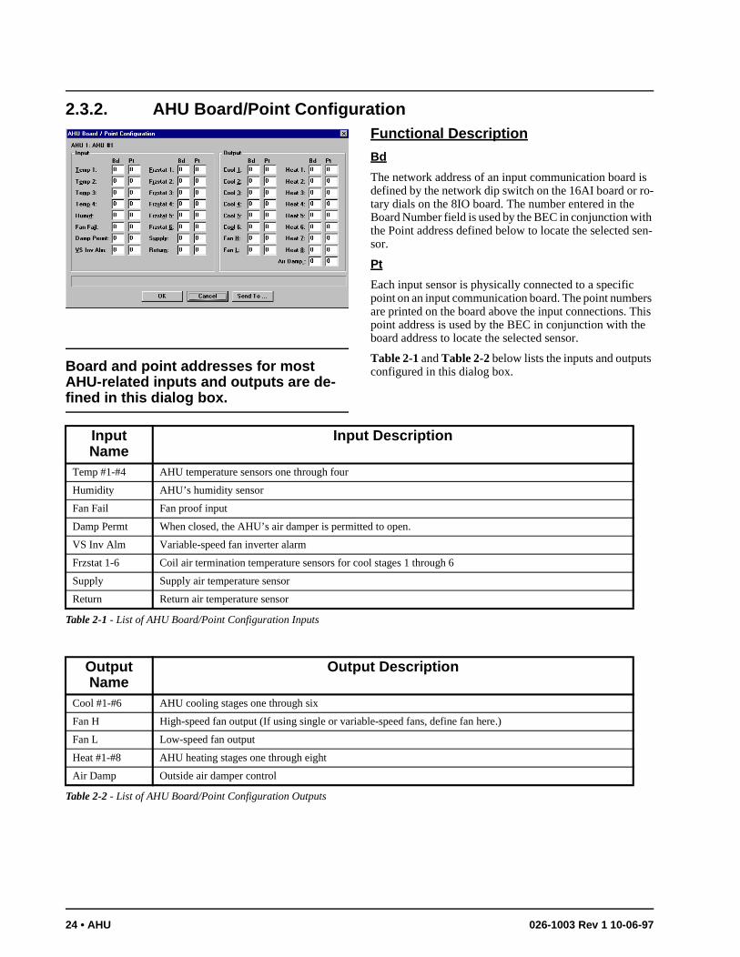
2.3.2. AHU Board/Point Configuration
Board and point addresses for most AHU-related inputs and outputs are de-fined in this dialog box.
Functional Description
Bd
The network address of an input communication board is defined by the network dip switch on the 16AI board or ro-tary dials on the 8IO board. The number entered in the Board Number field is used by the BEC in conjunction with the Point address defined below to locate the selected sen-sor.
Pt
Each input sensor is physically connected to a specific point on an input communication board. The point numbers are printed on the board above the input connections. This point address is used by the BEC in conjunction with the board address to locate the selected sensor.
Table 2-1 and Table 2-2 below lists the inputs and outputs configured in this dialog box.
Input Name
Input Description
Temp #1-#4 AHU temperature sensors one through four
Humidity AHU’s humidity sensor
Fan Fail Fan proof input
Damp Permt When closed, the AHU’s air damper is permitted to open.
VS Inv Alm Variable-speed fan inverter alarm
Frzstat 1-6 Coil air termination temperature sensors for cool stages 1 through 6
Supply Supply air temperature sensor
Return Return air temperature sensor
Table 2-1 - List of AHU Board/Point Configuration Inputs
Output Name
Output Description
Cool #1-#6 AHU cooling stages one through six
Fan H High-speed fan output (If using single or variable-speed fans, define fan here.)
Fan L Low-speed fan output
Heat #1-#8 AHU heating stages one through eight
Air Damp Outside air damper control
Table 2-2 - List of AHU Board/Point Configuration Outputs
24 • AHU 026-1003 Rev 1 10-06-97
en s’ f all e ate h
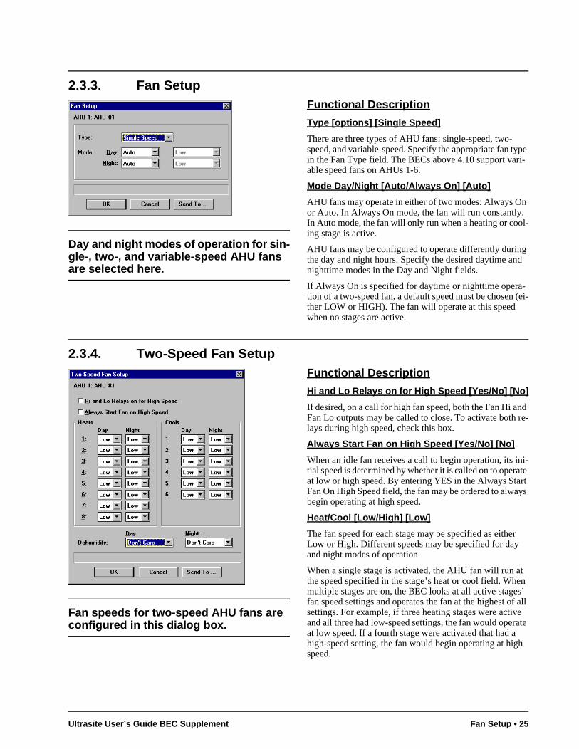
2.3.3. Fan Setup
Day and night modes of operation for sin-gle-, two-, and variable-speed AHU fans are selected here.
Functional Description
Type [options] [Single Speed]
There are three types of AHU fans: single-speed, two-speed, and variable-speed. Specify the appropriate fan type in the Fan Type field. The BECs above 4.10 support vari-able speed fans on AHUs 1-6.
Mode Day/Night [Auto/Always On] [Auto]
AHU fans may operate in either of two modes: Always On or Auto. In Always On mode, the fan will run constantly. In Auto mode, the fan will only run when a heating or cool-ing stage is active.
AHU fans may be configured to operate differently during the day and night hours. Specify the desired daytime and nighttime modes in the Day and Night fields.
If Always On is specified for daytime or nighttime opera-tion of a two-speed fan, a default speed must be chosen (ei-ther LOW or HIGH). The fan will operate at this speed when no stages are active.
2.3.4. Two-Speed Fan Setup
Fan speeds for two-speed AHU fans are configured in this dialog box.
Functional Description
Hi and Lo Relays on for High Speed [Yes/No] [No]
If desired, on a call for high fan speed, both the Fan Hi and Fan Lo outputs may be called to close. To activate both re-lays during high speed, check this box.
Always Start Fan on High Speed [Yes/No] [No]
When an idle fan receives a call to begin operation, its ini-tial speed is determined by whether it is called on to operate at low or high speed. By entering YES in the Always Start Fan On High Speed field, the fan may be ordered to always begin operating at high speed.
Heat/Cool [Low/High] [Low]
The fan speed for each stage may be specified as either Low or High. Different speeds may be specified for day and night modes of operation.
When a single stage is activated, the AHU fan will run at the speed specified in the stage’s heat or cool field. Whmultiple stages are on, the BEC looks at all active stagefan speed settings and operates the fan at the highest osettings. For example, if three heating stages were activand all three had low-speed settings, the fan would operat low speed. If a fourth stage were activated that had ahigh-speed setting, the fan would begin operating at higspeed.
Ultrasite User’s Guide BEC Supplement Fan Setup • 25
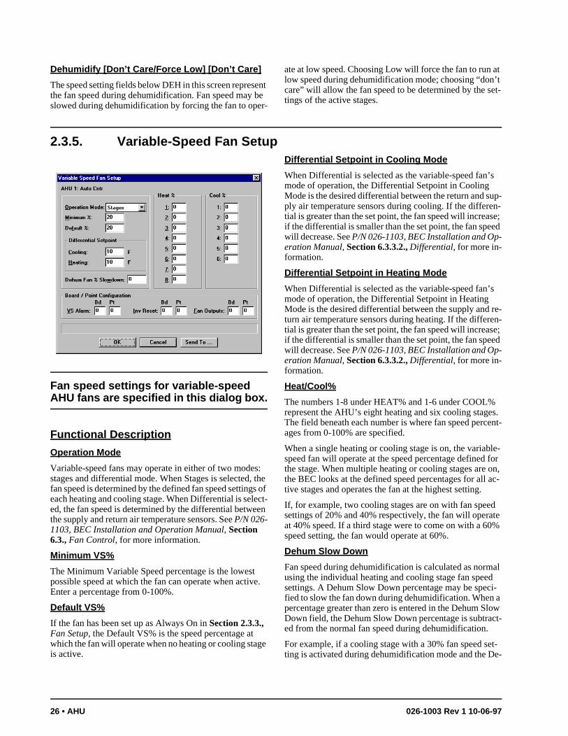
’t et-
s
up-n-se; ed
s
re-n-
se; ed
s. ent-
le- for on, ac-
d te %
al i-a low ct-
t-e-
Dehumidify [Don’t Care/Force Low] [Don’t Care]
The speed setting fields below DEH in this screen represent the fan speed during dehumidification. Fan speed may be slowed during dehumidification by forcing the fan to oper-
ate at low speed. Choosing Low will force the fan to run at low speed during dehumidification mode; choosing “doncare” will allow the fan speed to be determined by the stings of the active stages.
2.3.5. Variable-Speed Fan Setup
Fan speed settings for variable-speed AHU fans are specified in this dialog box.
Functional Description
Operation Mode
Variable-speed fans may operate in either of two modes: stages and differential mode. When Stages is selected, the fan speed is determined by the defined fan speed settings of each heating and cooling stage. When Differential is select-ed, the fan speed is determined by the differential between the supply and return air temperature sensors. See P/N 026-1103, BEC Installation and Operation Manual, Section 6.3., Fan Control, for more information.
Minimum VS%
The Minimum Variable Speed percentage is the lowest possible speed at which the fan can operate when active. Enter a percentage from 0-100%.
Default VS%
If the fan has been set up as Always On in Section 2.3.3., Fan Setup, the Default VS% is the speed percentage at which the fan will operate when no heating or cooling stage is active.
Differential Setpoint in Cooling Mode
When Differential is selected as the variable-speed fan’mode of operation, the Differential Setpoint in Cooling Mode is the desired differential between the return and sply air temperature sensors during cooling. If the differetial is greater than the set point, the fan speed will increaif the differential is smaller than the set point, the fan spewill decrease. See P/N 026-1103, BEC Installation and Op-eration Manual, Section 6.3.3.2., Differential, for more in-formation.
Differential Setpoint in Heating Mode
When Differential is selected as the variable-speed fan’mode of operation, the Differential Setpoint in Heating Mode is the desired differential between the supply and turn air temperature sensors during heating. If the differetial is greater than the set point, the fan speed will increaif the differential is smaller than the set point, the fan spewill decrease. See P/N 026-1103, BEC Installation and Op-eration Manual, Section 6.3.3.2., Differential, for more in-formation.
Heat/Cool%
The numbers 1-8 under HEAT% and 1-6 under COOL%represent the AHU’s eight heating and six cooling stageThe field beneath each number is where fan speed percages from 0-100% are specified.
When a single heating or cooling stage is on, the variabspeed fan will operate at the speed percentage definedthe stage. When multiple heating or cooling stages are the BEC looks at the defined speed percentages for all tive stages and operates the fan at the highest setting.
If, for example, two cooling stages are on with fan speesettings of 20% and 40% respectively, the fan will operaat 40% speed. If a third stage were to come on with a 60speed setting, the fan would operate at 60%.
Dehum Slow Down
Fan speed during dehumidification is calculated as normusing the individual heating and cooling stage fan speedsettings. A Dehum Slow Down percentage may be specfied to slow the fan down during dehumidification. When percentage greater than zero is entered in the Dehum SDown field, the Dehum Slow Down percentage is subtraed from the normal fan speed during dehumidification.
For example, if a cooling stage with a 30% fan speed seting is activated during dehumidification mode and the D
26 • AHU 026-1003 Rev 1 10-06-97
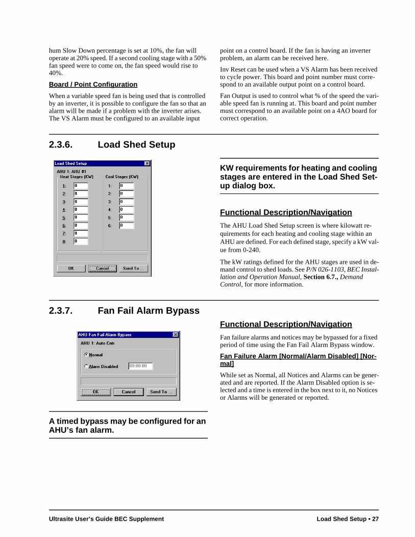
hum Slow Down percentage is set at 10%, the fan will operate at 20% speed. If a second cooling stage with a 50% fan speed were to come on, the fan speed would rise to 40%.
Board / Point Configuration
When a variable speed fan is being used that is controlled by an inverter, it is possible to configure the fan so that an alarm will be made if a problem with the inverter arises. The VS Alarm must be configured to an available input
point on a control board. If the fan is having an inverter problem, an alarm can be received here.
Inv Reset can be used when a VS Alarm has been received to cycle power. This board and point number must corre-spond to an available output point on a control board.
Fan Output is used to control what % of the speed the vari-able speed fan is running at. This board and point number must correspond to an available point on a 4AO board for correct operation.
2.3.6. Load Shed Setup
KW requirements for heating and cooling stages are entered in the Load Shed Set-up dialog box.
Functional Description/Navigation
The AHU Load Shed Setup screen is where kilowatt re-quirements for each heating and cooling stage within an AHU are defined. For each defined stage, specify a kW val-ue from 0-240.
The kW ratings defined for the AHU stages are used in de-mand control to shed loads. See P/N 026-1103, BEC Instal-lation and Operation Manual, Section 6.7., Demand Control, for more information.
2.3.7. Fan Fail Alarm Bypass
A timed bypass may be configured for an AHU’s fan alarm.
Functional Description/Navigation
Fan failure alarms and notices may be bypassed for a fixed period of time using the Fan Fail Alarm Bypass window.
Fan Failure Alarm [Normal/Alarm Disabled] [Nor-mal]
While set as Normal, all Notices and Alarms can be gener-ated and are reported. If the Alarm Disabled option is se-lected and a time is entered in the box next to it, no Notices or Alarms will be generated or reported.
Ultrasite User’s Guide BEC Supplement Load Shed Setup • 27
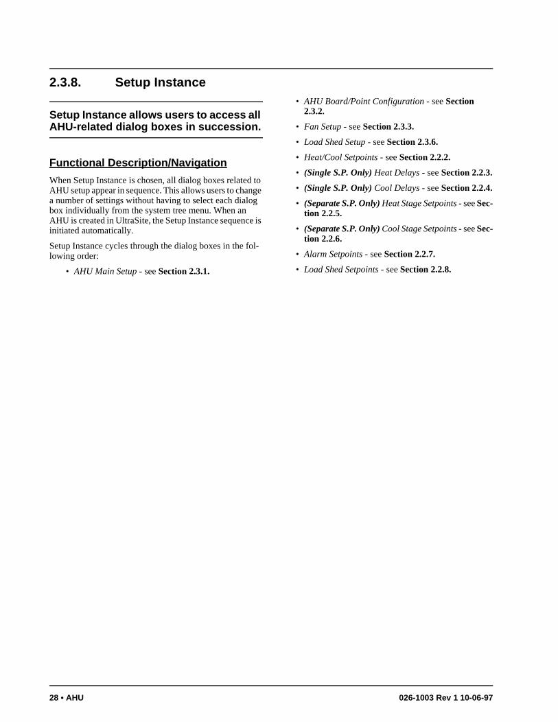
2.3.8. Setup Instance
Setup Instance allows users to access all AHU-related dialog boxes in succession.
Functional Description/Navigation
When Setup Instance is chosen, all dialog boxes related to AHU setup appear in sequence. This allows users to change a number of settings without having to select each dialog box individually from the system tree menu. When an AHU is created in UltraSite, the Setup Instance sequence is initiated automatically.
Setup Instance cycles through the dialog boxes in the fol-lowing order:
• AHU Main Setup - see Section 2.3.1.
• AHU Board/Point Configuration - see Section 2.3.2.
• Fan Setup - see Section 2.3.3.
• Load Shed Setup - see Section 2.3.6.
• Heat/Cool Setpoints - see Section 2.2.2.
• (Single S.P. Only) Heat Delays - see Section 2.2.3.
• (Single S.P. Only) Cool Delays - see Section 2.2.4.
• (Separate S.P. Only) Heat Stage Setpoints - see Sec-tion 2.2.5.
• (Separate S.P. Only) Cool Stage Setpoints - see Sec-tion 2.2.6.
• Alarm Setpoints - see Section 2.2.7.
• Load Shed Setpoints - see Section 2.2.8.
28 • AHU 026-1003 Rev 1 10-06-97
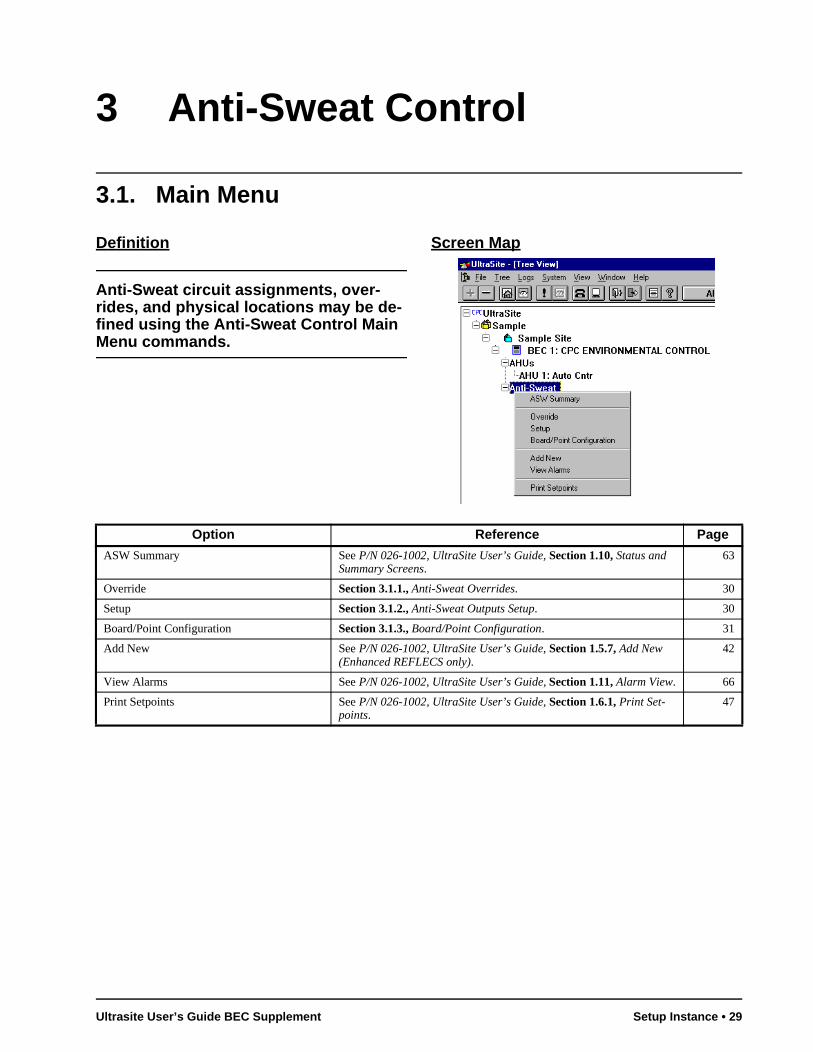
3 Anti-Sweat Control
3.1. Main Menu
Definition
Anti-Sweat circuit assignments, over-rides, and physical locations may be de-fined using the Anti-Sweat Control Main Menu commands.
Screen Map
Option Reference Page
ASW Summary See P/N 026-1002, UltraSite User’s Guide, Section 1.10, Status and Summary Screens.
63
Override Section 3.1.1., Anti-Sweat Overrides. 30
Setup Section 3.1.2., Anti-Sweat Outputs Setup. 30
Board/Point Configuration Section 3.1.3., Board/Point Configuration. 31
Add New See P/N 026-1002, UltraSite User’s Guide, Section 1.5.7, Add New (Enhanced REFLECS only).
42
View Alarms See P/N 026-1002, UltraSite User’s Guide, Section 1.11, Alarm View. 66
Print Setpoints See P/N 026-1002, UltraSite User’s Guide, Section 1.6.1, Print Set-points.
47
Ultrasite User’s Guide BEC Supplement Setup Instance • 29
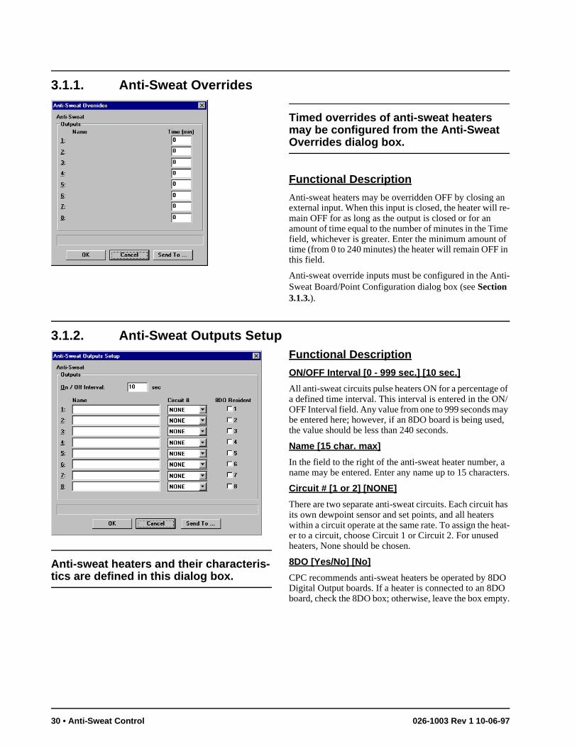
3.1.1. Anti-Sweat Overrides
Timed overrides of anti-sweat heaters may be configured from the Anti-Sweat Overrides dialog box.
Functional Description
Anti-sweat heaters may be overridden OFF by closing an external input. When this input is closed, the heater will re-main OFF for as long as the output is closed or for an amount of time equal to the number of minutes in the Time field, whichever is greater. Enter the minimum amount of time (from 0 to 240 minutes) the heater will remain OFF in this field.
Anti-sweat override inputs must be configured in the Anti-Sweat Board/Point Configuration dialog box (see Section 3.1.3.).
3.1.2. Anti-Sweat Outputs Setup
Anti-sweat heaters and their characteris-tics are defined in this dialog box.
Functional Description
ON/OFF Interval [0 - 999 sec.] [10 sec.]
All anti-sweat circuits pulse heaters ON for a percentage of a defined time interval. This interval is entered in the ON/OFF Interval field. Any value from one to 999 seconds may be entered here; however, if an 8DO board is being used, the value should be less than 240 seconds.
Name [15 char. max]
In the field to the right of the anti-sweat heater number, a name may be entered. Enter any name up to 15 characters.
Circuit # [1 or 2] [NONE]
There are two separate anti-sweat circuits. Each circuit has its own dewpoint sensor and set points, and all heaters within a circuit operate at the same rate. To assign the heat-er to a circuit, choose Circuit 1 or Circuit 2. For unused heaters, None should be chosen.
8DO [Yes/No] [No]
CPC recommends anti-sweat heaters be operated by 8DO Digital Output boards. If a heater is connected to an 8DO board, check the 8DO box; otherwise, leave the box empty.
30 • Anti-Sweat Control 026-1003 Rev 1 10-06-97
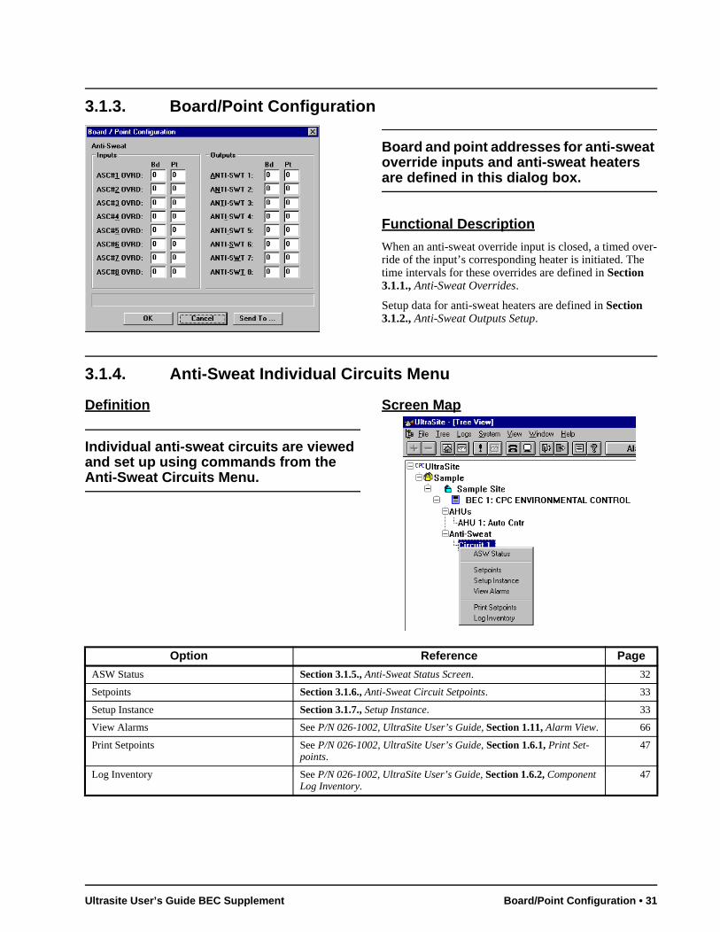
3.1.3. Board/Point Configuration
Board and point addresses for anti-sweat override inputs and anti-sweat heaters are defined in this dialog box.
Functional Description
When an anti-sweat override input is closed, a timed over-ride of the input’s corresponding heater is initiated. Thetime intervals for these overrides are defined in Section 3.1.1., Anti-Sweat Overrides.
Setup data for anti-sweat heaters are defined in Section 3.1.2., Anti-Sweat Outputs Setup.
3.1.4. Anti-Sweat Individual Circuits Menu
Definition
Individual anti-sweat circuits are viewed and set up using commands from the Anti-Sweat Circuits Menu.
Screen Map
Option Reference Page
ASW Status Section 3.1.5., Anti-Sweat Status Screen. 32
Setpoints Section 3.1.6., Anti-Sweat Circuit Setpoints. 33
Setup Instance Section 3.1.7., Setup Instance. 33
View Alarms See P/N 026-1002, UltraSite User’s Guide, Section 1.11, Alarm View. 66
Print Setpoints See P/N 026-1002, UltraSite User’s Guide, Section 1.6.1, Print Set-points.
47
Log Inventory See P/N 026-1002, UltraSite User’s Guide, Section 1.6.2, Component Log Inventory.
47
Ultrasite User’s Guide BEC Supplement Board/Point Configuration • 31
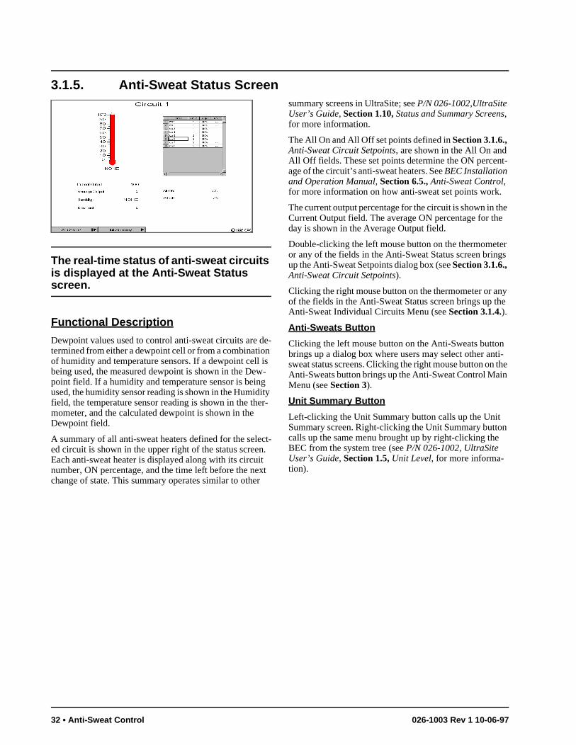
he e
er gs
ny e
ti- the n
n
3.1.5. Anti-Sweat Status Screen
The real-time status of anti-sweat circuits is displayed at the Anti-Sweat Status screen.
Functional Description
Dewpoint values used to control anti-sweat circuits are de-termined from either a dewpoint cell or from a combination of humidity and temperature sensors. If a dewpoint cell is being used, the measured dewpoint is shown in the Dew-point field. If a humidity and temperature sensor is being used, the humidity sensor reading is shown in the Humidity field, the temperature sensor reading is shown in the ther-mometer, and the calculated dewpoint is shown in the Dewpoint field.
A summary of all anti-sweat heaters defined for the select-ed circuit is shown in the upper right of the status screen. Each anti-sweat heater is displayed along with its circuit number, ON percentage, and the time left before the next change of state. This summary operates similar to other
summary screens in UltraSite; see P/N 026-1002,UltraSite User’s Guide, Section 1.10, Status and Summary Screens, for more information.
The All On and All Off set points defined in Section 3.1.6., Anti-Sweat Circuit Setpoints, are shown in the All On and All Off fields. These set points determine the ON percent-age of the circuit’s anti-sweat heaters. See BEC Installation and Operation Manual, Section 6.5., Anti-Sweat Control, for more information on how anti-sweat set points work.
The current output percentage for the circuit is shown in tCurrent Output field. The average ON percentage for thday is shown in the Average Output field.
Double-clicking the left mouse button on the thermometor any of the fields in the Anti-Sweat Status screen brinup the Anti-Sweat Setpoints dialog box (see Section 3.1.6., Anti-Sweat Circuit Setpoints).
Clicking the right mouse button on the thermometer or aof the fields in the Anti-Sweat Status screen brings up thAnti-Sweat Individual Circuits Menu (see Section 3.1.4.).
Anti-Sweats Button
Clicking the left mouse button on the Anti-Sweats buttonbrings up a dialog box where users may select other answeat status screens. Clicking the right mouse button onAnti-Sweats button brings up the Anti-Sweat Control MaiMenu (see Section 3).
Unit Summary Button
Left-clicking the Unit Summary button calls up the Unit Summary screen. Right-clicking the Unit Summary buttocalls up the same menu brought up by right-clicking theBEC from the system tree (see P/N 026-1002, UltraSite User’s Guide, Section 1.5, Unit Level, for more informa-tion).
32 • Anti-Sweat Control 026-1003 Rev 1 10-06-97
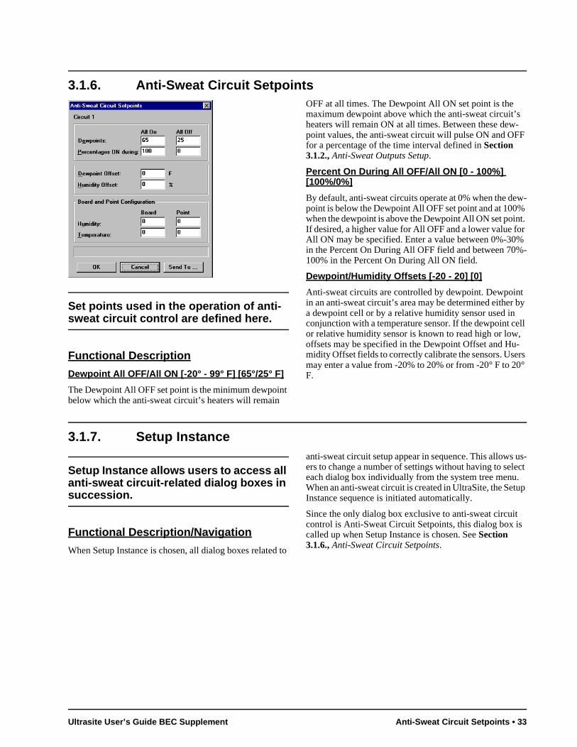
-F
w-
t. r
% -
t by
ell , -rs °
us-ect . up
3.1.6. Anti-Sweat Circuit Setpoints
Set points used in the operation of anti-sweat circuit control are defined here.
Functional Description
Dewpoint All OFF/All ON [-20° - 99° F] [65°/25° F]
The Dewpoint All OFF set point is the minimum dewpoint below which the anti-sweat circuit’s heaters will remain
OFF at all times. The Dewpoint All ON set point is the maximum dewpoint above which the anti-sweat circuit’sheaters will remain ON at all times. Between these dewpoint values, the anti-sweat circuit will pulse ON and OFfor a percentage of the time interval defined in Section 3.1.2., Anti-Sweat Outputs Setup.
Percent On During All OFF/All ON [0 - 100%] [100%/0%]
By default, anti-sweat circuits operate at 0% when the depoint is below the Dewpoint All OFF set point and at 100%when the dewpoint is above the Dewpoint All ON set poinIf desired, a higher value for All OFF and a lower value foAll ON may be specified. Enter a value between 0%-30in the Percent On During All OFF field and between 70%100% in the Percent On During All ON field.
Dewpoint/Humidity Offsets [-20 - 20] [0]
Anti-sweat circuits are controlled by dewpoint. Dewpoinin an anti-sweat circuit’s area may be determined either a dewpoint cell or by a relative humidity sensor used in conjunction with a temperature sensor. If the dewpoint cor relative humidity sensor is known to read high or lowoffsets may be specified in the Dewpoint Offset and Humidity Offset fields to correctly calibrate the sensors. Usemay enter a value from -20% to 20% or from -20° F to 20F.
3.1.7. Setup Instance
Setup Instance allows users to access all anti-sweat circuit-related dialog boxes in succession.
Functional Description/Navigation
When Setup Instance is chosen, all dialog boxes related to
anti-sweat circuit setup appear in sequence. This allowsers to change a number of settings without having to seleach dialog box individually from the system tree menuWhen an anti-sweat circuit is created in UltraSite, the SetInstance sequence is initiated automatically.
Since the only dialog box exclusive to anti-sweat circuitcontrol is Anti-Sweat Circuit Setpoints, this dialog box iscalled up when Setup Instance is chosen. See Section 3.1.6., Anti-Sweat Circuit Setpoints.
Ultrasite User’s Guide BEC Supplement Anti-Sweat Circuit Setpoints • 33
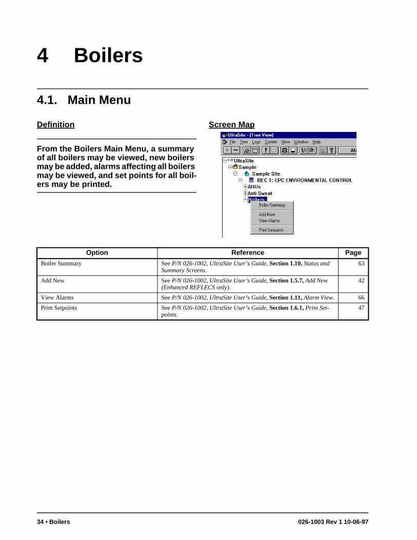
4 Boilers
4.1. Main Menu
Definition
From the Boilers Main Menu, a summary of all boilers may be viewed, new boilers may be added, alarms affecting all boilers may be viewed, and set points for all boil-ers may be printed.
Screen Map
Option Reference Page
Boiler Summary See P/N 026-1002, UltraSite User’s Guide, Section 1.10, Status and Summary Screens.
63
Add New See P/N 026-1002, UltraSite User’s Guide, Section 1.5.7, Add New (Enhanced REFLECS only).
42
View Alarms See P/N 026-1002, UltraSite User’s Guide, Section 1.11, Alarm View. 66
Print Setpoints See P/N 026-1002, UltraSite User’s Guide, Section 1.6.1, Print Set-points.
47
34 • Boilers 026-1003 Rev 1 10-06-97
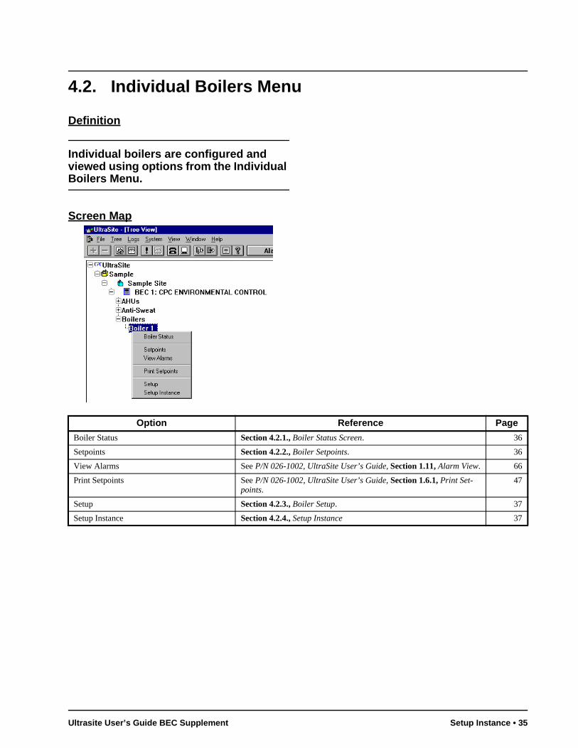
4.2. Individual Boilers Menu
Definition
Individual boilers are configured and viewed using options from the Individual Boilers Menu.
Screen Map
Option Reference Page
Boiler Status Section 4.2.1., Boiler Status Screen. 36
Setpoints Section 4.2.2., Boiler Setpoints. 36
View Alarms See P/N 026-1002, UltraSite User’s Guide, Section 1.11, Alarm View. 66
Print Setpoints See P/N 026-1002, UltraSite User’s Guide, Section 1.6.1, Print Set-points.
47
Setup Section 4.2.3., Boiler Setup. 37
Setup Instance Section 4.2.4., Setup Instance 37
Ultrasite User’s Guide BEC Supplement Setup Instance • 35
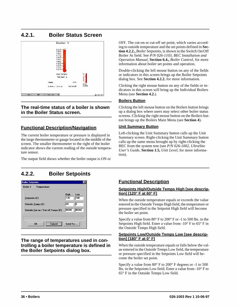
e n
0 to
4.2.1. Boiler Status Screen
The real-time status of a boiler is shown in the Boiler Status screen.
Functional Description/Navigation
The current boiler temperature or pressure is displayed in the large thermometer or gauge located in the middle of the screen. The smaller thermometer to the right of the boiler indicator shows the current reading of the outside tempera-ture sensor.
The output field shows whether the boiler output is ON or
OFF. The cut-on or cut-off set point, which varies accord-ing to outside temperature and the set points defined in Sec-tion 4.2.2., Boiler Setpoints, is shown in the Switch On/Off Boiler At field. See P/N 026-1103, BEC Installation and Operation Manual, Section 6.4., Boiler Control, for more information about boiler set points and operation.
Double-clicking the left mouse button on any of the fields or indicators in this screen brings up the Boiler Setpoints dialog box. See Section 4.2.2. for more information.
Clicking the right mouse button on any of the fields or in-dicators in this screen will bring up the Individual Boilers Menu (see Section 4.2.).
Boilers Button
Clicking the left mouse button on the Boilers button brings up a dialog box where users may select other boiler status screens. Clicking the right mouse button on the Boilers but-ton brings up the Boilers Main Menu (see Section 4).
Unit Summary Button
Left-clicking the Unit Summary button calls up the Unit Summary screen. Right-clicking the Unit Summary button calls up the same menu brought up by right-clicking the BEC from the system tree (see P/N 026-1002, UltraSite User’s Guide, Section 1.5, Unit Level, for more informa-tion).
4.2.2. Boiler Setpoints
The range of temperatures used in con-trolling a boiler temperature is defined in the Boiler Setpoints dialog box.
Functional Description
Setpoints High/Outside Temps High [see descrip-tion] [120° F at 60° F]
When the outside temperature equals or exceeds the value entered in the Outside Temps High field, the temperature or pressure specified in the Setpoint High field will become the boiler set point.
Specify a value from 80° F to 200° F or -1 to 500 lbs. in thSetpoints High field. Enter a value from -10° F to 65° F ithe Outside Temps High field.
Setpoints Low/Outside Temps Low [see descrip-tion] [180° F at 0° F]
When the outside temperature equals or falls below the val-ue entered in the Outside Temps Low field, the temperature or pressure specified in the Setpoints Low field will be-come the boiler set point.
Specify a value from 80° F to 200° F degrees or -1 to 50lbs. in the Setpoints Low field. Enter a value from -10° F 65° F in the Outside Temps Low field.
36 • Boilers 026-1003 Rev 1 10-06-97
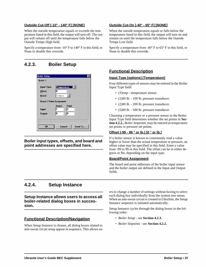
r
iler
iler
e
Outside Cut-Off [-10° - 140° F] [NONE]
When the outside temperature equals or exceeds the tem-perature listed in this field, the output will turn off. The out-put will remain off until the temperature falls below the Outside Temps High field.
Specify a temperature from -10° F to 140° F in this field, or None to disable this override.
Outside Cut-On [-40° - 65° F] [NONE]
When the outside temperature equals or falls below the temperature listed in this field, the output will turn on and remain on until the temperature falls below the Outside Temps Low field.
Specify a temperature from -40° F to 65° F in this field, oNone to disable this override.
4.2.3. Boiler Setup
Boiler input types, offsets, and board and point addresses are specified here.
Functional Description
Input Type [options] [Temperature]
Four different types of sensors may be entered in the BoInput Type field:
• (T)emp - temperature sensor.
• (1)00 lb. - 100 lb. pressure transducer.
• (2)00 lb. - 200 lb. pressure transducer.
• (5)00 lb. - 500 lb. pressure transducer.
Choosing a temperature or a pressure sensor in the BoInput Type field determines whether the set points in Sec-tion 4.2.2., Boiler Setpoints, may be entered as temperaturset points or pressure set points.
Offset [-99 - 99 ° or lb.] [0 ° or lb.]
If a boiler sensor is known to consistently read a value higher or lower than the actual temperature or pressure, an offset value may be specified in this field. Enter a value from -99 to 99 in this field. The offset can be in either de-grees or lbs. depending on the input type.
Board/Point Assignment
The board and point addresses of the boiler input sensor and the boiler output are defined in the Input and Output fields.
4.2.4. Setup Instance
Setup Instance allows users to access all boiler-related dialog boxes in succes-sion.
Functional Description/Navigation
When Setup Instance is chosen, all dialog boxes related to anti-sweat circuit setup appear in sequence. This allows us-
ers to change a number of settings without having to select each dialog box individually from the system tree menu. When an anti-sweat circuit is created in UltraSite, the Setup Instance sequence is initiated automatically.
Setup Instance cycles through the dialog boxes in the fol-lowing order:
• Boiler Setup - see Section 4.2.3.
• Boiler Setpoints - see Section 4.2.2.
Ultrasite User’s Guide BEC Supplement Boiler Setup • 37
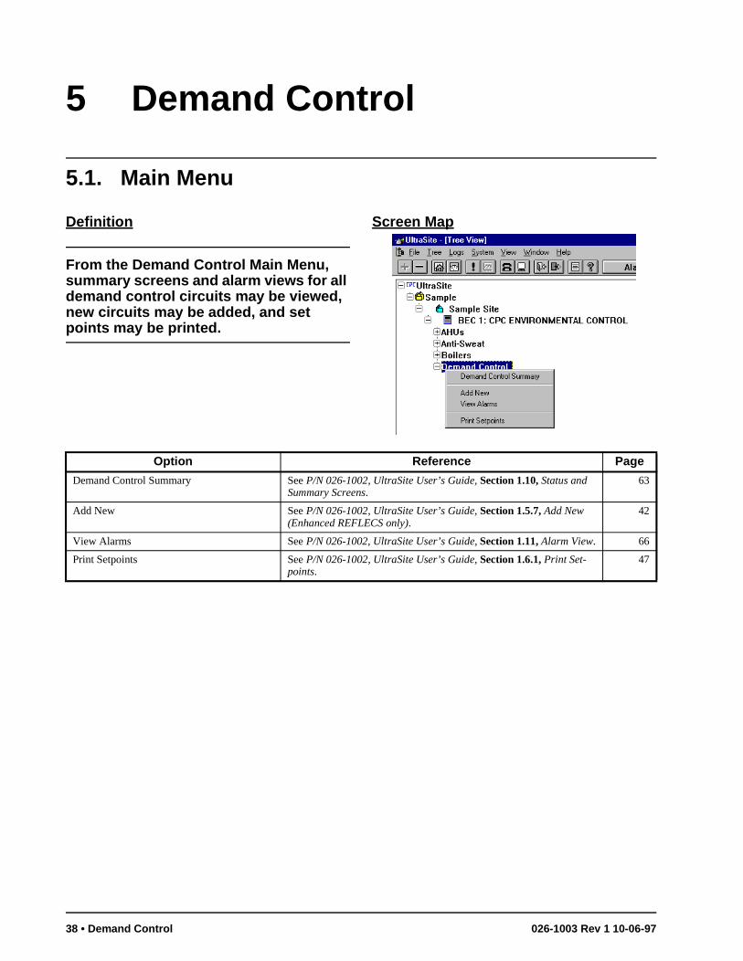
5 Demand Control
5.1. Main Menu
Definition
From the Demand Control Main Menu, summary screens and alarm views for all demand control circuits may be viewed, new circuits may be added, and set points may be printed.
Screen Map
Option Reference Page
Demand Control Summary See P/N 026-1002, UltraSite User’s Guide, Section 1.10, Status and Summary Screens.
63
Add New See P/N 026-1002, UltraSite User’s Guide, Section 1.5.7, Add New (Enhanced REFLECS only).
42
View Alarms See P/N 026-1002, UltraSite User’s Guide, Section 1.11, Alarm View. 66
Print Setpoints See P/N 026-1002, UltraSite User’s Guide, Section 1.6.1, Print Set-points.
47
38 • Demand Control 026-1003 Rev 1 10-06-97
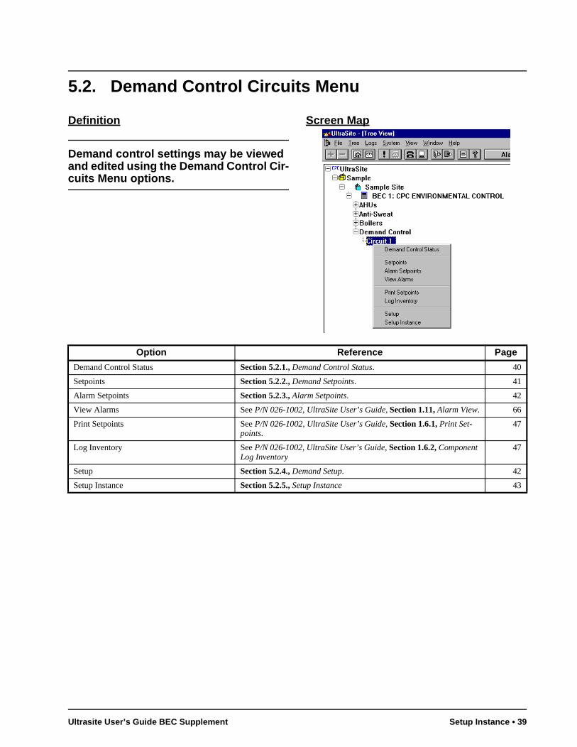
5.2. Demand Control Circuits Menu
Definition
Demand control settings may be viewed and edited using the Demand Control Cir-cuits Menu options.
Screen Map
Option Reference Page
Demand Control Status Section 5.2.1., Demand Control Status. 40
Setpoints Section 5.2.2., Demand Setpoints. 41
Alarm Setpoints Section 5.2.3., Alarm Setpoints. 42
View Alarms See P/N 026-1002, UltraSite User’s Guide, Section 1.11, Alarm View. 66
Print Setpoints See P/N 026-1002, UltraSite User’s Guide, Section 1.6.1, Print Set-points.
47
Log Inventory See P/N 026-1002, UltraSite User’s Guide, Section 1.6.2, Component Log Inventory
47
Setup Section 5.2.4., Demand Setup. 42
Setup Instance Section 5.2.5., Setup Instance 43
Ultrasite User’s Guide BEC Supplement Setup Instance • 39
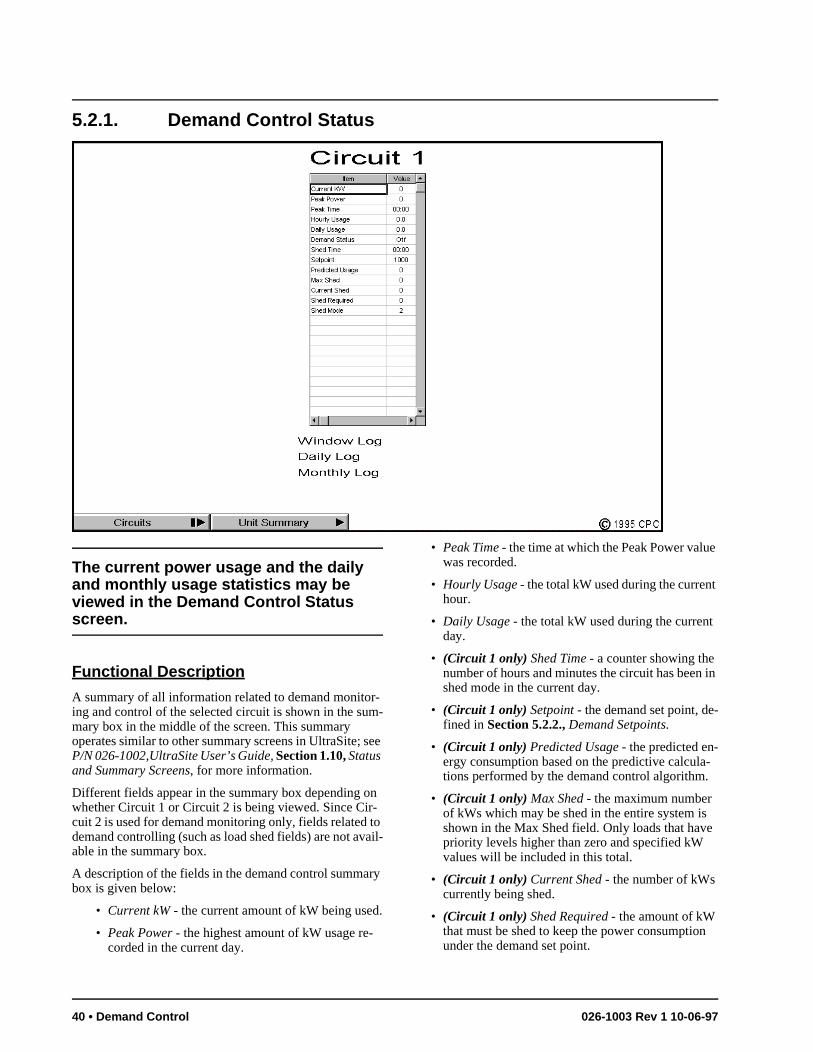
e
t
in
-
-
e
5.2.1. Demand Control Status
The current power usage and the daily and monthly usage statistics may be viewed in the Demand Control Status screen.
Functional Description
A summary of all information related to demand monitor-ing and control of the selected circuit is shown in the sum-mary box in the middle of the screen. This summary operates similar to other summary screens in UltraSite; see P/N 026-1002,UltraSite User’s Guide, Section 1.10, Status and Summary Screens, for more information.
Different fields appear in the summary box depending on whether Circuit 1 or Circuit 2 is being viewed. Since Cir-cuit 2 is used for demand monitoring only, fields related to demand controlling (such as load shed fields) are not avail-able in the summary box.
A description of the fields in the demand control summary box is given below:
• Current kW - the current amount of kW being used.
• Peak Power - the highest amount of kW usage re-corded in the current day.
• Peak Time - the time at which the Peak Power valuwas recorded.
• Hourly Usage - the total kW used during the currenhour.
• Daily Usage - the total kW used during the currentday.
• (Circuit 1 only) Shed Time - a counter showing the number of hours and minutes the circuit has beenshed mode in the current day.
• (Circuit 1 only) Setpoint - the demand set point, defined in Section 5.2.2., Demand Setpoints.
• (Circuit 1 only) Predicted Usage - the predicted en-ergy consumption based on the predictive calculations performed by the demand control algorithm.
• (Circuit 1 only) Max Shed - the maximum number of kWs which may be shed in the entire system isshown in the Max Shed field. Only loads that havpriority levels higher than zero and specified kW values will be included in this total.
• (Circuit 1 only) Current Shed - the number of kWs currently being shed.
• (Circuit 1 only) Shed Required - the amount of kW that must be shed to keep the power consumptionunder the demand set point.
40 • Demand Control 026-1003 Rev 1 10-06-97
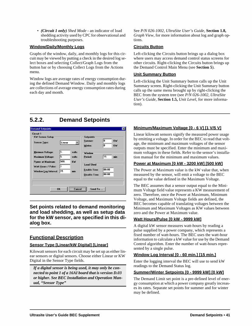
lla-
n
i- of
the n
r d
-
r-as-ter
• (Circuit 1 only) Shed Mode - an indicator of load shedding activity used by CPC for observational and troubleshooting purposes.
Window/Daily/Monthly Logs
Graphs of the window, daily, and monthly logs for this cir-cuit may be viewed by putting a check in the desired log se-lect boxes and selecting Collect/Graph Logs from the button bar or by choosing Collect Logs from the Actions menu.
Window logs are average rates of energy consumption dur-ing the defined Demand Window. Daily and monthly logs are collections of average energy consumption rates during each day and month.
See P/N 026-1002, UltraSite User’s Guide, Section 1.8, Graph View, for more information about log and graph op-tions.
Circuits Button
Left-clicking the Circuits button brings up a dialog box where users may access demand control status screens for other circuits. Right-clicking the Circuits button brings up the Demand Control Main Menu (see Section 5).
Unit Summary Button
Left-clicking the Unit Summary button calls up the Unit Summary screen. Right-clicking the Unit Summary button calls up the same menu brought up by right-clicking the BEC from the system tree (see P/N 026-1002, UltraSite User’s Guide, Section 1.5, Unit Level, for more informa-tion).
5.2.2. Demand Setpoints
Set points related to demand monitoring and load shedding, as well as setup data for the kW sensor, are specified in this di-alog box.
Functional DescriptionSensor Type [Linear/kW Digital] [Linear]
Kilowatt sensors for each circuit may be set up as either lin-ear sensors or digital sensors. Choose either Linear or KW Digital in the Sensor Type fields.
Minimum/Maximum Voltage [0 - 6 V] [1 V/5 V]
Linear kilowatt sensors signify the measured power usage by emitting a voltage. In order for the BEC to read that volt-age, the minimum and maximum voltages of the sensor outputs must be specified. Enter the minimum and maxi-mum voltages in these fields. Refer to the sensor’s instation manual for the minimum and maximum values.
Power at Maximum [0 kW - 3200 kW] [500 kW]
The Power at Maximum value is the kW value that, whemeasured by the sensor, will emit a voltage to the BEC equal to the value defined in the Maximum Voltage.
The BEC assumes that a sensor output equal to the Minmum Voltage field value represents a KW measurementzero. Therefore, once the Power at Maximum, MinimumVoltage, and Maximum Voltage fields are defined, the BEC becomes capable of translating voltages between Minimum and Maximum Voltages as KW values betweezero and the Power at Maximum value.
Watt Hours/Pulse [0 kW - 9999 kW]
A digital kW sensor measures watt-hours by reading a pulse supplied by a power company, which represents afixed number of watt-hours. The BEC uses the watt-houinformation to calculate a kW value for use by the DemanControl algorithm. Enter the number of watt-hours represented by a single pulse.
Window Log Interval [0 - 60 min.] [15 min.]
Enter the logging interval the BEC will use to send kW readings to the Demand Status log.
Summer/Winter Setpoints [0 - 9999 kW] [0 kW]
The Demand Limit set point is a pre-defined level of enegy consumption at which a power company greatly increes its rates. Separate set points for summer and for winmay be defined.
If a digital sensor is being used, it may only be con-nected to point 1 of a 16AI board that is version D.03 or higher. See BEC Installation and Operation Man-ual, “Sensor Type”
Ultrasite User’s Guide BEC Supplement Demand Setpoints • 41
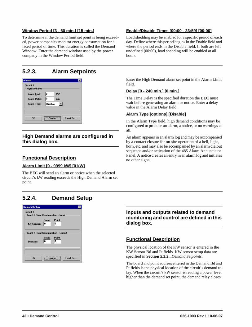
it
at
ied lout r
tes
and e-el es.
Window Period [3 - 60 min.] [15 min.]
To determine if the demand limit set point is being exceed-ed, power companies monitor energy consumption for a fixed period of time. This duration is called the Demand Window. Enter the demand window used by the power company in the Window Period field.
Enable/Disable Times [00:00 - 23:59] [00:00]
Load shedding may be enabled for a specific period of each day. Define where this period begins in the Enable field and where the period ends in the Disable field. If both are left undefined (00:00), load shedding will be enabled at all hours.
5.2.3. Alarm Setpoints
High Demand alarms are configured in this dialog box.
Functional Description
Alarm Limit [0 - 9999 kW] [0 kW]
The BEC will send an alarm or notice when the selected circuit’s kW reading exceeds the High Demand Alarm set point.
Enter the High Demand alarm set point in the Alarm Limfield.
Delay [0 - 240 min.] [0 min.]
The Time Delay is the specified duration the BEC must wait before generating an alarm or notice. Enter a delayvalue in the Alarm Delay field.
Alarm Type [options] [Disable]
In the Alarm Type field, high demand conditions may beconfigured to produce an alarm, a notice, or no warningsall.
An alarm appears in an alarm log and may be accompanby a contact closure for on-site operation of a bell, light,horn, etc. and may also be accompanied by an alarm diasequence and/or activation of the 485 Alarm AnnunciatoPanel. A notice creates an entry in an alarm log and initiano other signal.
5.2.4. Demand Setup
Inputs and outputs related to demand monitoring and control are defined in this dialog box.
Functional Description
The physical location of the KW sensor is entered in theKW Sensor Bd and Pt fields. KW sensor setup data arespecified in Section 5.2.2., Demand Setpoints.
The board and point address entered in the Demand Bd Pt fields is the physical location of the circuit’s demand rlay. When the circuit’s kW sensor is reading a power levhigher than the demand set point, the demand relay clos
42 • Demand Control 026-1003 Rev 1 10-06-97
5.2.5. Setup Instance
Setup Instance allows users to access all demand circuit-related dialog boxes in succession.
Functional Description
When Setup Instance is chosen, all dialog boxes related to demand circuits appear in sequence. This allows users to
change a number of settings without having to select each dialog box individually from the system tree menu. When a demand circuit is created in UltraSite, the Setup Instance sequence is initiated automatically.
Setup Instance cycles through the dialog boxes in the fol-lowing order:
• Demand Setup - see Section 5.2.4.
• Demand Setpoints - see Section 5.2.2.
• Demand Alarms - see Section 5.2.3.
Ultrasite User’s Guide BEC Supplement Setup Instance • 43
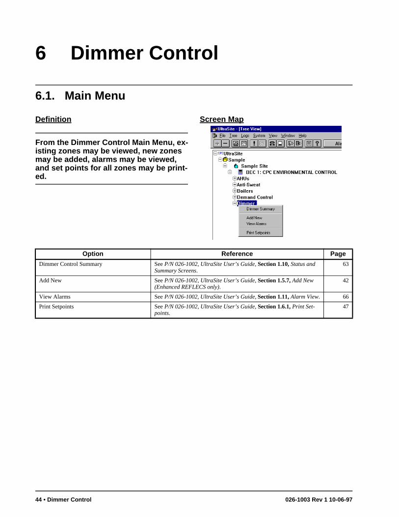
6 Dimmer Control
6.1. Main Menu
Definition
From the Dimmer Control Main Menu, ex-isting zones may be viewed, new zones may be added, alarms may be viewed, and set points for all zones may be print-ed.
Screen Map
Option Reference Page
Dimmer Control Summary See P/N 026-1002, UltraSite User’s Guide, Section 1.10, Status and Summary Screens.
63
Add New See P/N 026-1002, UltraSite User’s Guide, Section 1.5.7, Add New (Enhanced REFLECS only).
42
View Alarms See P/N 026-1002, UltraSite User’s Guide, Section 1.11, Alarm View. 66
Print Setpoints See P/N 026-1002, UltraSite User’s Guide, Section 1.6.1, Print Set-points.
47
44 • Dimmer Control 026-1003 Rev 1 10-06-97
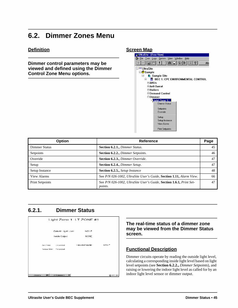
6.2. Dimmer Zones Menu
Definition
Dimmer control parameters may be viewed and defined using the Dimmer Control Zone Menu options.
Screen Map
6.2.1. Dimmer Status
The real-time status of a dimmer zone may be viewed from the Dimmer Status screen.
Functional Description
Dimmer circuits operate by reading the outside light level, calculating a corresponding inside light level based on light level setpoints (see Section 6.2.2., Dimmer Setpoints), and raising or lowering the indoor light level as called for by an indoor light level sensor or dimmer output.
Option Reference Page
Dimmer Status Section 6.2.1., Dimmer Status. 45
Setpoints Section 6.2.2., Dimmer Setpoints. 46
Override Section 6.2.3., Dimmer Override. 47
Setup Section 6.2.4., Dimmer Setup. 47
Setup Instance Section 6.2.5., Setup Instance 48
View Alarms See P/N 026-1002, UltraSite User’s Guide, Section 1.11, Alarm View. 66
Print Setpoints See P/N 026-1002, UltraSite User’s Guide, Section 1.6.1, Print Set-points.
47
Ultrasite User’s Guide BEC Supplement Dimmer Status • 45
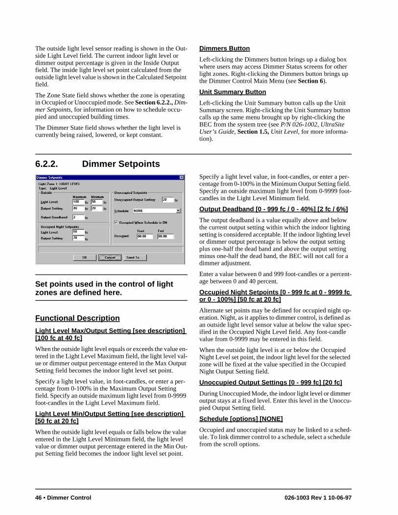
The outside light level sensor reading is shown in the Out-side Light Level field. The current indoor light level or dimmer output percentage is given in the Inside Output field. The inside light level set point calculated from the outside light level value is shown in the Calculated Setpoint field.
The Zone State field shows whether the zone is operating in Occupied or Unoccupied mode. See Section 6.2.2., Dim-mer Setpoints, for information on how to schedule occu-pied and unoccupied building times.
The Dimmer State field shows whether the light level is currently being raised, lowered, or kept constant.
Dimmers Button
Left-clicking the Dimmers button brings up a dialog box where users may access Dimmer Status screens for other light zones. Right-clicking the Dimmers button brings up the Dimmer Control Main Menu (see Section 6).
Unit Summary Button
Left-clicking the Unit Summary button calls up the Unit Summary screen. Right-clicking the Unit Summary button calls up the same menu brought up by right-clicking the BEC from the system tree (see P/N 026-1002, UltraSite User’s Guide, Section 1.5, Unit Level, for more informa-tion).
6.2.2. Dimmer Setpoints
Set points used in the control of light zones are defined here.
Functional Description
Light Level Max/Output Setting [see description] [100 fc at 40 fc]
When the outside light level equals or exceeds the value en-tered in the Light Level Maximum field, the light level val-ue or dimmer output percentage entered in the Max Output Setting field becomes the indoor light level set point.
Specify a light level value, in foot-candles, or enter a per-centage from 0-100% in the Maximum Output Setting field. Specify an outside maximum light level from 0-9999 foot-candles in the Light Level Maximum field.
Light Level Min/Output Setting [see description] [50 fc at 20 fc]
When the outside light level equals or falls below the value entered in the Light Level Minimum field, the light level value or dimmer output percentage entered in the Min Out-put Setting field becomes the indoor light level set point.
Specify a light level value, in foot-candles, or enter a per-centage from 0-100% in the Minimum Output Setting field. Specify an outside maximum light level from 0-9999 foot-candles in the Light Level Minimum field.
Output Deadband [0 - 999 fc / 0 - 40%] [2 fc / 6%]
The output deadband is a value equally above and below the current output setting within which the indoor lighting setting is considered acceptable. If the indoor lighting level or dimmer output percentage is below the output setting plus one-half the dead band and above the output setting minus one-half the dead band, the BEC will not call for a dimmer adjustment.
Enter a value between 0 and 999 foot-candles or a percent-age between 0 and 40 percent.
Occupied Night Setpoints [0 - 999 fc at 0 - 9999 fc or 0 - 100%] [50 fc at 20 fc]
Alternate set points may be defined for occupied night op-eration. Night, as it applies to dimmer control, is defined as an outside light level sensor value at below the value spec-ified in the Occupied Night Level field. Any foot-candle value from 0-9999 may be entered in this field.
When the outside light level is at or below the Occupied Night Level set point, the indoor light level for the selected zone will be fixed at the value specified in the Occupied Night Output Setting field.
Unoccupied Output Settings [0 - 999 fc] [20 fc]
During Unoccupied Mode, the indoor light level or dimmer output stays at a fixed level. Enter this level in the Unoccu-pied Output Setting field.
Schedule [options] [NONE]
Occupied and unoccupied status may be linked to a sched-ule. To link dimmer control to a schedule, select a schedule from the scroll options.
46 • Dimmer Control 026-1003 Rev 1 10-06-97
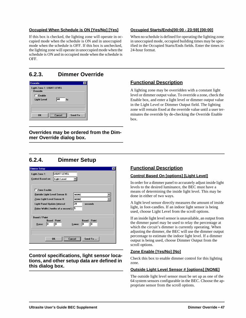
ut r
the ap-
Occupied When Schedule is ON [Yes/No] [Yes]
If this box is checked, the lighting zone will operate in oc-cupied mode when the schedule is ON and in unoccupied mode when the schedule is OFF. If this box is unchecked, the lighting zone will operate in unoccupied mode when the schedule is ON and in occupied mode when the schedule is OFF.
Occupied Starts/Ends[00:00 - 23:59] [00:00]
When no schedule is defined for operating the lighting zone in unoccupied mode, occupied building times may be spec-ified in the Occupied Starts/Ends fields. Enter the times in 24-hour format.
6.2.3. Dimmer Override
Overrides may be ordered from the Dim-mer Override dialog box.
Functional Description
A lighting zone may be overridden with a constant light level or dimmer output value. To override a zone, check the Enable box, and enter a light level or dimmer output value in the Light Level or Dimmer Output field. The lighting zone will remain fixed at the override value until a user ter-minates the override by de-checking the Override Enable box.
6.2.4. Dimmer Setup
Control specifications, light sensor loca-tions, and other setup data are defined in this dialog box.
Functional Description
Control Based On [options] [Light Level]
In order for a dimmer panel to accurately adjust inside light levels to the desired luminance, the BEC must have a means of determining the inside light level. This may be done in either of two ways.
A light level sensor directly measures the amount of inside light, in foot-candles. If an indoor light sensor is being used, choose Light Level from the scroll options.
If an inside light level sensor is unavailable, an output from the dimmer panel may be used to relay the percentage at which the circuit’s dimmer is currently operating. When adjusting the dimmer, the BEC will use the dimmer outppercentage to estimate the indoor light level. If a dimmeoutput is being used, choose Dimmer Output from the scroll options.
Zone Enable [Yes/No] [No]
Check this box to enable dimmer control for this lightingzone.
Outside Light Level Sensor # [options] [NONE]
The outside light level sensor must be set up as one of 64 system sensors configurable in the BEC. Choose thepropriate sensor from the scroll options.
Ultrasite User’s Guide BEC Supplement Dimmer Override • 47
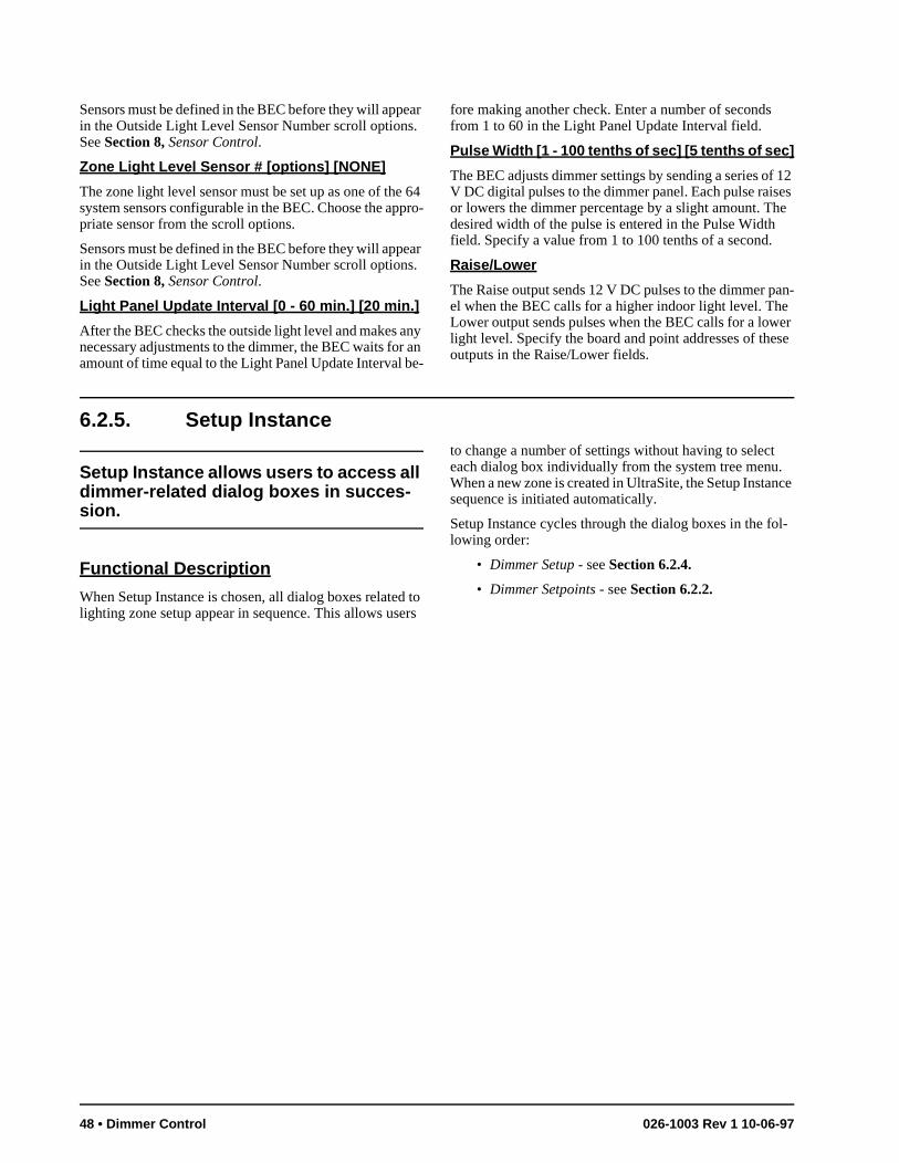
Sensors must be defined in the BEC before they will appear in the Outside Light Level Sensor Number scroll options. See Section 8, Sensor Control.
Zone Light Level Sensor # [options] [NONE]
The zone light level sensor must be set up as one of the 64 system sensors configurable in the BEC. Choose the appro-priate sensor from the scroll options.
Sensors must be defined in the BEC before they will appear in the Outside Light Level Sensor Number scroll options. See Section 8, Sensor Control.
Light Panel Update Interval [0 - 60 min.] [20 min.]
After the BEC checks the outside light level and makes any necessary adjustments to the dimmer, the BEC waits for an amount of time equal to the Light Panel Update Interval be-
fore making another check. Enter a number of seconds from 1 to 60 in the Light Panel Update Interval field.
Pulse Width [1 - 100 tenths of sec] [5 tenths of sec]
The BEC adjusts dimmer settings by sending a series of 12 V DC digital pulses to the dimmer panel. Each pulse raises or lowers the dimmer percentage by a slight amount. The desired width of the pulse is entered in the Pulse Width field. Specify a value from 1 to 100 tenths of a second.
Raise/Lower
The Raise output sends 12 V DC pulses to the dimmer pan-el when the BEC calls for a higher indoor light level. The Lower output sends pulses when the BEC calls for a lower light level. Specify the board and point addresses of these outputs in the Raise/Lower fields.
6.2.5. Setup Instance
Setup Instance allows users to access all dimmer-related dialog boxes in succes-sion.
Functional Description
When Setup Instance is chosen, all dialog boxes related to lighting zone setup appear in sequence. This allows users
to change a number of settings without having to select each dialog box individually from the system tree menu. When a new zone is created in UltraSite, the Setup Instance sequence is initiated automatically.
Setup Instance cycles through the dialog boxes in the fol-lowing order:
• Dimmer Setup - see Section 6.2.4.
• Dimmer Setpoints - see Section 6.2.2.
48 • Dimmer Control 026-1003 Rev 1 10-06-97
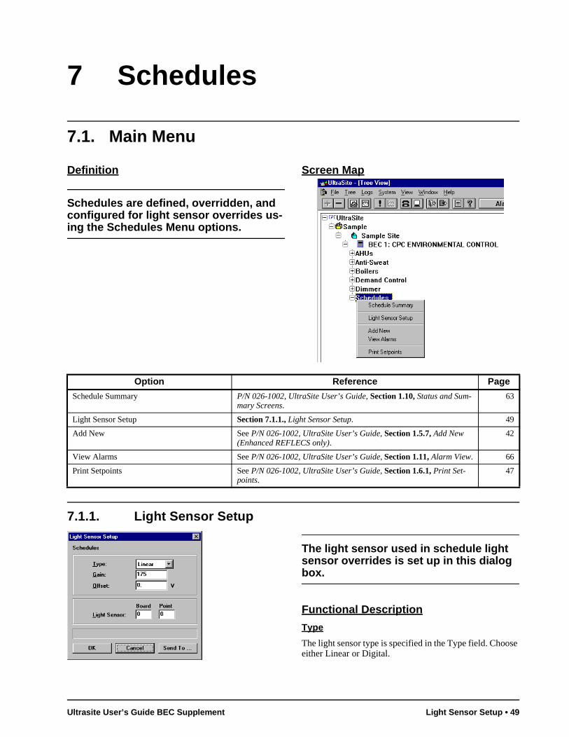
7 Schedules
7.1. Main Menu
Definition
Schedules are defined, overridden, and configured for light sensor overrides us-ing the Schedules Menu options.
Screen Map
7.1.1. Light Sensor Setup
The light sensor used in schedule light sensor overrides is set up in this dialog box.
Functional Description
Type
The light sensor type is specified in the Type field. Choose either Linear or Digital.
Option Reference Page
Schedule Summary P/N 026-1002, UltraSite User’s Guide, Section 1.10, Status and Sum-mary Screens.
63
Light Sensor Setup Section 7.1.1., Light Sensor Setup. 49
Add New See P/N 026-1002, UltraSite User’s Guide, Section 1.5.7, Add New (Enhanced REFLECS only).
42
View Alarms See P/N 026-1002, UltraSite User’s Guide, Section 1.11, Alarm View. 66
Print Setpoints See P/N 026-1002, UltraSite User’s Guide, Section 1.6.1, Print Set-points.
47
Ultrasite User’s Guide BEC Supplement Light Sensor Setup • 49
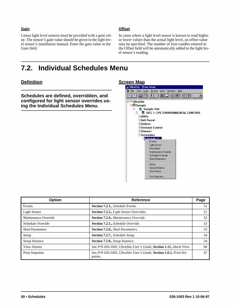
er e n -
Gain
Linear light level sensors must be provided with a gain val-ue. The sensor’s gain value should be given in the light lev-el sensor’s installation manual. Enter the gain value in the Gain field.
Offset
In cases where a light level sensor is known to read highor lower values than the actual light level, an offset valumay be specified. The number of foot-candles entered ithe Offset field will be automatically added to the light level sensor’s reading.
7.2. Individual Schedules Menu
Definition
Schedules are defined, overridden, and configured for light sensor overrides us-ing the Individual Schedules Menu.
Screen Map
Option Reference Page
Events Section 7.2.1., Schedule Events. 51
Light Sensor Section 7.2.2., Light Sensor Overrides. 51
Maintenance Override Section 7.2.4., Maintenance Override. 52
Schedule Override Section 7.2.5., Schedule Override. 53
Shed Parameters Section 7.2.6., Shed Parameters. 53
Setup Section 7.2.7., Schedule Setup. 54
Setup Instance Section 7.2.8., Setup Instance. 54
View Alarms See P/N 026-1002, UltraSite User’s Guide, Section 1.11, Alarm View. 66
Print Setpoints See P/N 026-1002, UltraSite User’s Guide, Section 1.6.1, Print Set-points.
47
50 • Schedules 026-1003 Rev 1 10-06-97
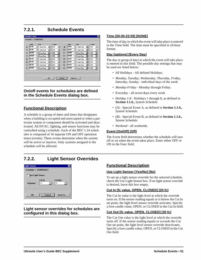
ed
e y
rn or
le, de
t In ify d.
ut . ut
7.2.1. Schedule Events
On/off events for schedules are defined in the Schedule Events dialog box.
Functional Description
A schedule is a group of dates and times that designates when a building is occupied and unoccupied or when a par-ticular system or component should be activated and deac-tivated. All HVAC, lighting, and sensor functions may be controlled using a schedule. Each of the BEC’s 24 sched-ules is composed of 16 separate ON and OFF operation times (events). These events determine when the system will be active or inactive. Only systems assigned to the schedule will be affected.
Time [00:00-23:59] [NONE]
The time of day in which the event will take place is enterin the Time field. The time must be specified in 24-hourformat.
Day [options] [Every Day]
The day or group of days in which the event will take placis entered in this field. The possible day settings that mabe used are listed below:
• All Holidays - All defined Holidays.
• Monday, Tuesday, Wednesday, Thursday, Friday, Saturday, Sunday - individual days of the week.
• Monday-Friday - Monday through Friday.
• Everyday - all seven days every week
• Holiday 1-8 - Holidays 1 through 8, as defined in Section 1.1.6., System Schedule.
• (A) - Special Event A, as defined in Section 1.1.6., System Schedule.
• (B) - Special Event B, as defined in Section 1.1.6., System Schedule.
• Weekend - all weekends.
Event [On/Off] [Off]
The Event field determines whether the schedule will tuoff or on when the event takes place. Enter either OFF ON in the Func field.
7.2.2. Light Sensor Overrides
Light sensor overrides for schedules are configured in this dialog box.
Functional Description
Use Light Sensor [Yes/No] [No]
To set up a light sensor override for the selected scheducheck the Use Light Sensor box. If no light sensor overriis desired, leave this box empty.
Cut In [fc value, OPEN, CLOSED] [20 fc]
The Cut In value is the light level at which the override turns on. If the sensor reading equals or is below the Cuset point, the light level sensor override activates. Speca foot-candle value, OPEN, or CLOSED in the Cut In fiel
Cut Out [fc value, OPEN, CLOSED] [30 fc]
The Cut Out value is the light level at which the overrideturns off. If the sensor reading equals or exceeds the COut set point, the light level sensor override deactivatesSpecify a foot-candle value, OPEN, or CLOSED in the COut field.
Ultrasite User’s Guide BEC Supplement Schedule Events • 51
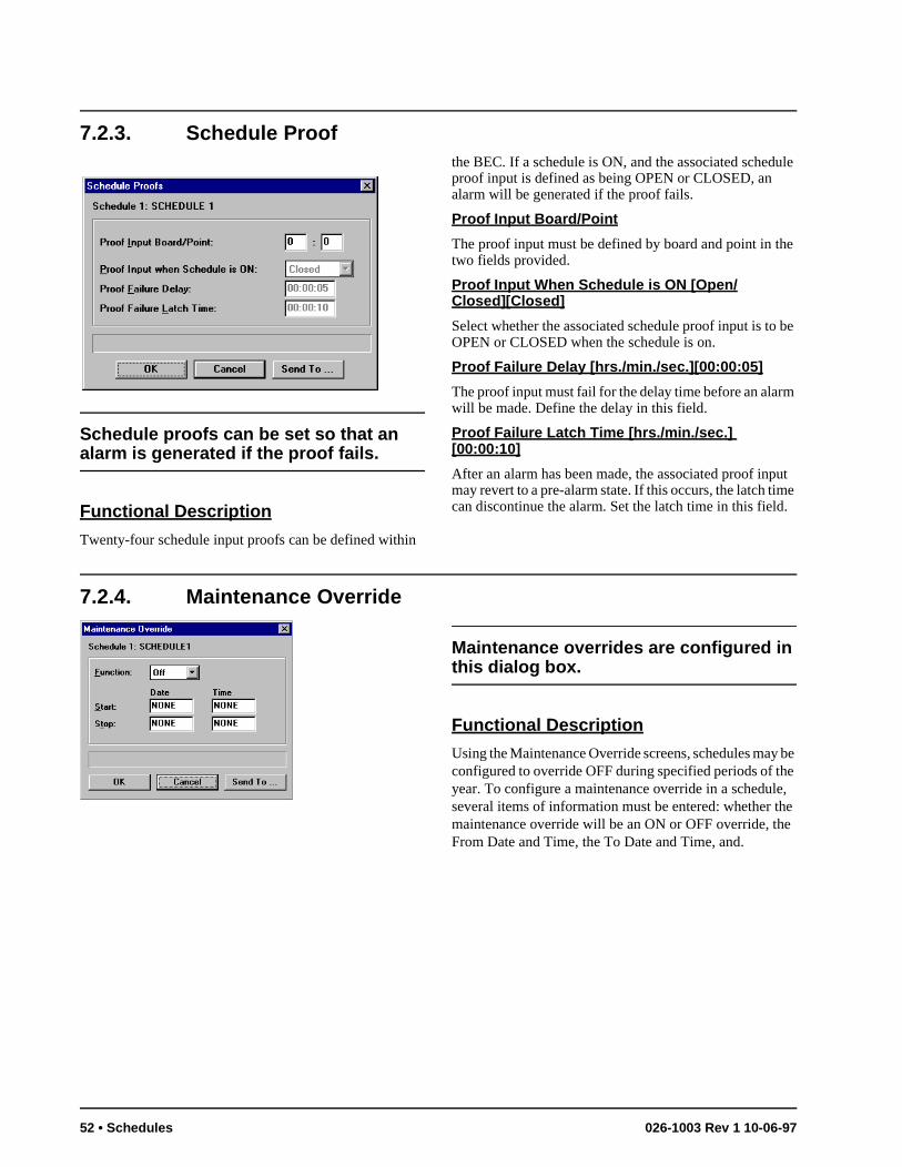
7.2.3. Schedule Proof
Schedule proofs can be set so that an alarm is generated if the proof fails.
Functional Description
Twenty-four schedule input proofs can be defined within
the BEC. If a schedule is ON, and the associated schedule proof input is defined as being OPEN or CLOSED, an alarm will be generated if the proof fails.
Proof Input Board/Point
The proof input must be defined by board and point in the two fields provided.
Proof Input When Schedule is ON [Open/Closed][Closed]
Select whether the associated schedule proof input is to be OPEN or CLOSED when the schedule is on.
Proof Failure Delay [hrs./min./sec.][00:00:05]
The proof input must fail for the delay time before an alarm will be made. Define the delay in this field.
Proof Failure Latch Time [hrs./min./sec.] [00:00:10]
After an alarm has been made, the associated proof input may revert to a pre-alarm state. If this occurs, the latch time can discontinue the alarm. Set the latch time in this field.
7.2.4. Maintenance Override
Maintenance overrides are configured in this dialog box.
Functional Description
Using the Maintenance Override screens, schedules may be configured to override OFF during specified periods of the year. To configure a maintenance override in a schedule, several items of information must be entered: whether the maintenance override will be an ON or OFF override, the From Date and Time, the To Date and Time, and.
52 • Schedules 026-1003 Rev 1 10-06-97
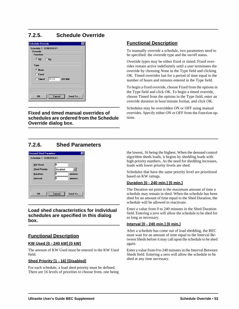
7.2.5. Schedule Override
Fixed and timed manual overrides of schedules are ordered from the Schedule Override dialog box.
Functional Description
To manually override a schedule, two parameters need to be specified: the override type and the on/off status.
Override types may be either fixed or timed. Fixed over-rides remain active indefinitely until a user terminates the override by choosing None in the Type field and clicking OK. Timed overrides last for a period of time equal to the number of hours and minutes entered in the Type field.
To begin a fixed override, choose Fixed from the options in the Type field and click OK. To begin a timed override, choose Timed from the options in the Type field, enter an override duration in hour:minute format, and click OK.
Schedules may be overridden ON or OFF using manual overrides. Specify either ON or OFF from the Function op-tions.
7.2.6. Shed Parameters
Load shed characteristics for individual schedules are specified in this dialog box.
Functional Description
KW Used [0 - 240 kW] [0 kW]
The amount of KW Used must be entered in the KW Used field.
Shed Priority [1 - 16] [Disabled]
For each schedule, a load shed priority must be defined. There are 16 levels of priorities to choose from, one being
the lowest, 16 being the highest. When the demand control algorithm sheds loads, it begins by shedding loads with high priority numbers. As the need for shedding increases, loads with lower priority levels are shed.
Schedules that have the same priority level are prioritized based on KW ratings.
Duration [0 - 240 min.] [0 min.]
The Duration set point is the maximum amount of time a schedule may remain in shed. When the schedule has been shed for an amount of time equal to the Shed Duration, the schedule will be allowed to reactivate.
Enter a value from 0 to 240 minutes in the Shed Duration field. Entering a zero will allow the schedule to be shed for as long as necessary.
Interval [0 - 240 min.] [0 min.]
After a schedule has come out of load shedding, the BEC must wait for an amount of time equal to the Interval Be-tween Sheds before it may call upon the schedule to be shed again.
Enter a value from 0 to 240 minutes in the Interval Between Sheds field. Entering a zero will allow the schedule to be shed at any time necessary.
Ultrasite User’s Guide BEC Supplement Schedule Override • 53
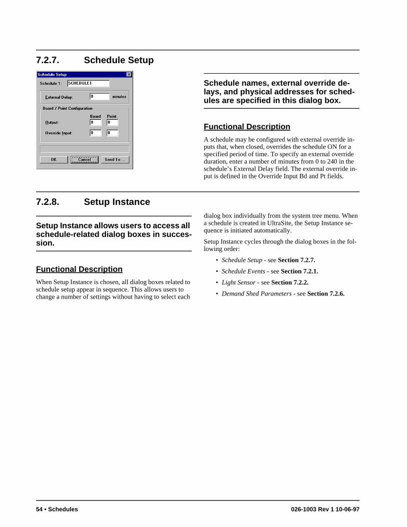
-
n -
l-
7.2.7. Schedule Setup
Schedule names, external override de-lays, and physical addresses for sched-ules are specified in this dialog box.
Functional Description
A schedule may be configured with external override in-puts that, when closed, overrides the schedule ON for a specified period of time. To specify an external override duration, enter a number of minutes from 0 to 240 in the schedule’s External Delay field. The external override input is defined in the Override Input Bd and Pt fields.
7.2.8. Setup Instance
Setup Instance allows users to access all schedule-related dialog boxes in succes-sion.
Functional Description
When Setup Instance is chosen, all dialog boxes related to schedule setup appear in sequence. This allows users to change a number of settings without having to select each
dialog box individually from the system tree menu. Whea schedule is created in UltraSite, the Setup Instance sequence is initiated automatically.
Setup Instance cycles through the dialog boxes in the folowing order:
• Schedule Setup - see Section 7.2.7.
• Schedule Events - see Section 7.2.1.
• Light Sensor - see Section 7.2.2.
• Demand Shed Parameters - see Section 7.2.6.
54 • Schedules 026-1003 Rev 1 10-06-97
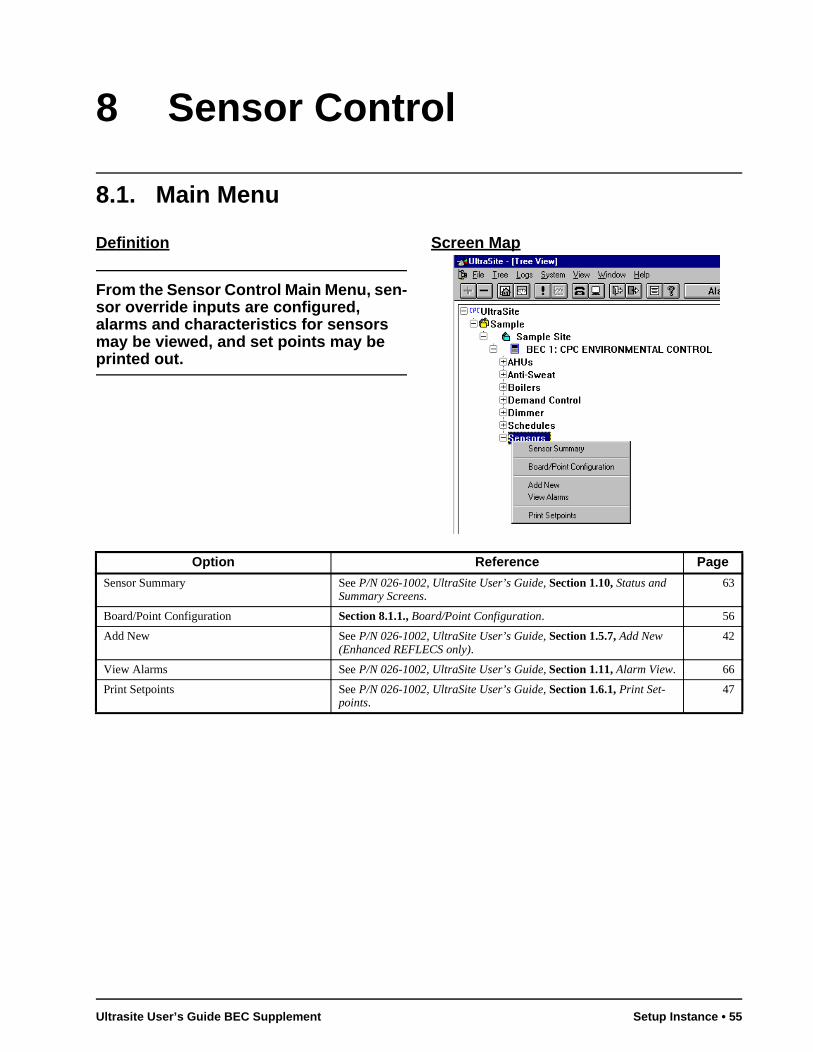
8 Sensor Control
8.1. Main Menu
Definition
From the Sensor Control Main Menu, sen-sor override inputs are configured, alarms and characteristics for sensors may be viewed, and set points may be printed out.
Screen Map
Option Reference Page
Sensor Summary See P/N 026-1002, UltraSite User’s Guide, Section 1.10, Status and Summary Screens.
63
Board/Point Configuration Section 8.1.1., Board/Point Configuration. 56
Add New See P/N 026-1002, UltraSite User’s Guide, Section 1.5.7, Add New (Enhanced REFLECS only).
42
View Alarms See P/N 026-1002, UltraSite User’s Guide, Section 1.11, Alarm View. 66
Print Setpoints See P/N 026-1002, UltraSite User’s Guide, Section 1.6.1, Print Set-points.
47
Ultrasite User’s Guide BEC Supplement Setup Instance • 55
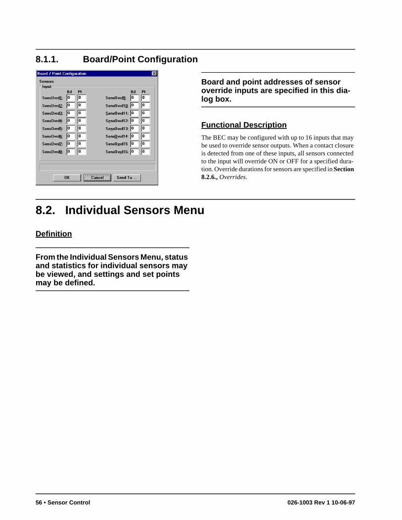
8.1.1. Board/Point Configuration
Board and point addresses of sensor override inputs are specified in this dia-log box.
Functional Description
The BEC may be configured with up to 16 inputs that may be used to override sensor outputs. When a contact closure is detected from one of these inputs, all sensors connected to the input will override ON or OFF for a specified dura-tion. Override durations for sensors are specified in Section 8.2.6., Overrides.
8.2. Individual Sensors Menu
Definition
From the Individual Sensors Menu, status and statistics for individual sensors may be viewed, and settings and set points may be defined.
56 • Sensor Control 026-1003 Rev 1 10-06-97
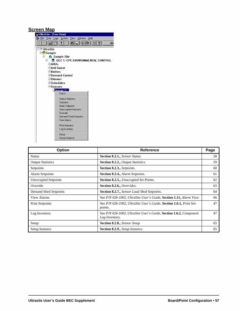
Screen Map
Option Reference Page
Status Section 8.2.1., Sensor Status. 58
Output Statistics Section 8.2.2., Output Statistics. 59
Setpoints Section 8.2.3., Setpoints. 60
Alarm Setpoints Section 8.2.4., Alarm Setpoints. 61
Unoccupied Setpoints Section 8.2.5., Unoccupied Set Points. 62
Override Section 8.2.6., Overrides. 63
Demand Shed Setpoints Section 8.2.7., Sensor Load Shed Setpoints. 64
View Alarms See P/N 026-1002, UltraSite User’s Guide, Section 1.11, Alarm View. 66
Print Setpoints See P/N 026-1002, UltraSite User’s Guide, Section 1.6.1, Print Set-points.
47
Log Inventory See P/N 026-1002, UltraSite User’s Guide, Section 1.6.2, Component Log Inventory.
47
Setup Section 8.2.8., Sensor Setup 65
Setup Instance Section 8.2.9., Setup Instance. 65
Ultrasite User’s Guide BEC Supplement Board/Point Configuration • 57
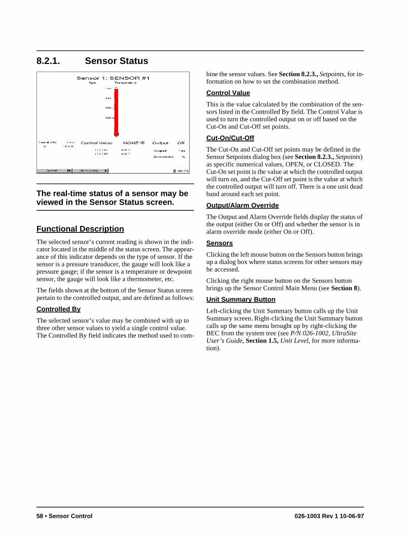
n-s
e
ut h d
of n
gs ay
n
8.2.1. Sensor Status
The real-time status of a sensor may be viewed in the Sensor Status screen.
Functional Description
The selected sensor’s current reading is shown in the indi-cator located in the middle of the status screen. The appear-ance of this indicator depends on the type of sensor. If the sensor is a pressure transducer, the gauge will look like a pressure gauge; if the sensor is a temperature or dewpoint sensor, the gauge will look like a thermometer, etc.
The fields shown at the bottom of the Sensor Status screen pertain to the controlled output, and are defined as follows:
Controlled By
The selected sensor’s value may be combined with up to three other sensor values to yield a single control value. The Controlled By field indicates the method used to com-
bine the sensor values. See Section 8.2.3., Setpoints, for in-formation on how to set the combination method.
Control Value
This is the value calculated by the combination of the sesors listed in the Controlled By field. The Control Value iused to turn the controlled output on or off based on theCut-On and Cut-Off set points.
Cut-On/Cut-Off
The Cut-On and Cut-Off set points may be defined in thSensor Setpoints dialog box (see Section 8.2.3., Setpoints) as specific numerical values, OPEN, or CLOSED. The Cut-On set point is the value at which the controlled outpwill turn on, and the Cut-Off set point is the value at whicthe controlled output will turn off. There is a one unit deaband around each set point.
Output/Alarm Override
The Output and Alarm Override fields display the status the output (either On or Off) and whether the sensor is ialarm override mode (either On or Off).
Sensors
Clicking the left mouse button on the Sensors button brinup a dialog box where status screens for other sensors mbe accessed.
Clicking the right mouse button on the Sensors button brings up the Sensor Control Main Menu (see Section 8).
Unit Summary Button
Left-clicking the Unit Summary button calls up the Unit Summary screen. Right-clicking the Unit Summary buttocalls up the same menu brought up by right-clicking theBEC from the system tree (see P/N 026-1002, UltraSite User’s Guide, Section 1.5, Unit Level, for more informa-tion).
58 • Sensor Control 026-1003 Rev 1 10-06-97
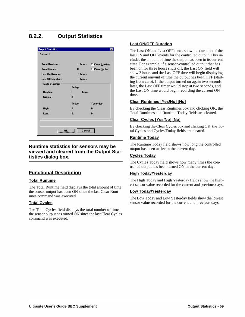
8.2.2. Output Statistics
Runtime statistics for sensors may be viewed and cleared from the Output Sta-tistics dialog box.
Functional Description
Total Runtime
The Total Runtime field displays the total amount of time the sensor output has been ON since the last Clear Runt-imes command was executed.
Total Cycles
The Total Cycles field displays the total number of times the sensor output has turned ON since the last Clear Cycles command was executed.
Last ON/OFF Duration
The Last ON and Last OFF times show the duration of the last ON and OFF events for the controlled output. This in-cludes the amount of time the output has been in its current state. For example, if a sensor-controlled output that has been on for three hours shuts off, the Last ON field will show 3 hours and the Last OFF time will begin displaying the current amount of time the output has been OFF (start-ing from zero). If the output turned on again two seconds later, the Last OFF timer would stop at two seconds, and the Last ON time would begin recording the current ON time.
Clear Runtimes [Yes/No] [No]
By checking the Clear Runtimes box and clicking OK, the Total Runtimes and Runtime Today fields are cleared.
Clear Cycles [Yes/No] [No]
By checking the Clear Cycles box and clicking OK, the To-tal Cycles and Cycles Today fields are cleared.
Runtime Today
The Runtime Today field shows how long the controlled output has been active in the current day.
Cycles Today
The Cycles Today field shows how many times the con-trolled output has been turned ON in the current day.
High Today/Yesterday
The High Today and High Yesterday fields show the high-est sensor value recorded for the current and previous days.
Low Today/Yesterday
The Low Today and Low Yesterday fields show the lowest sensor value recorded for the current and previous days.
Ultrasite User’s Guide BEC Supplement Output Statistics • 59
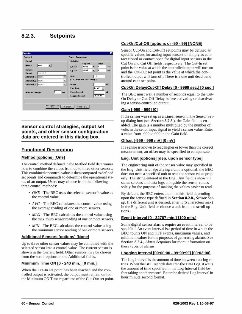
s n-e
n
ut-t-
Set-
f ter
ct e.
in rop-
es d.
x)
be e ee
n-its
in
8.2.3. Setpoints
Sensor control strategies, output set points, and other sensor configuration data are entered in this dialog box.
Functional Description
Method [options] [One]
The control method defined in the Method field determines how to combine the values from up to three other sensors. This combined or control value is then compared to defined set points and commands to determine the operational sta-tus of an output. Users may choose from the following three control methods:
• ONE - The BEC uses the selected sensor’s value as the control value.
• AVG - The BEC calculates the control value using the average reading of one or more sensors.
• MAX - The BEC calculates the control value using the maximum sensor reading of one or more sensors.
• MIN - The BEC calculates the control value using the minimum sensor reading of one or more sensors.
Additional Sensors [options] [None]
Up to three other sensor values may be combined with the selected sensor into a control value. The current sensor is shown in the Current field. Other sensors may be chosen from the scroll options in the Additional fields.
Minimum Time ON [0 - 240 min.] [0 min.]
When the Cut-In set point has been reached and the con-trolled output is activated, the output must remain on for the Minimum ON Time regardless of the Cut-Out set point.
Cut-On/Cut-Off [options or -50 - 99] [NONE]
Sensor Cut-On and Cut-Off set points may be defined aspecific values for analog input sensors or simply as cotact closed or contact open for digital input sensors in thCut On and Cut Off fields respectively. The Cut-In set point is the value at which the controlled output will turn oand the Cut-Out set point is the value at which the con-trolled output will turn off. There is a one unit dead bandaround each set point.
Cut-On Delay/Cut-Off Delay [0 - 9999 sec.] [0 sec.]
The BEC must wait a number of seconds equal to the COn Delay or Cut-Off Delay before activating or deactivaing a sensor-controlled output.
Gain [-999 - 999] [0]
If the sensor was set up as a Linear sensor in the Sensorup dialog box (see Section 8.2.8.), the Gain field is en-abled. The gain is a number multiplied by the number ovolts in the senor input signal to yield a sensor value. Ena value from -999 to 999 in the Gain field.
Offset [-999 - 999 mV] [0 mV]
If a sensor is known to read higher or lower than the corremeasurement, an offset may be specified to compensat
Eng. Unit [options] [dep. upon sensor type]
The engineering unit of the sensor value may specified the Eng. Unit field. Specifying a unit is optional; the BECdoes not need a specified unit to read the sensor value perly. The string entered in the Eng. Unit field is shown instatus screens and data logs alongside the sensor valusolely for the purpose of making the values easier to rea
By default, the BEC enters a unit in this field dependingupon the sensor type defined in Section 8.2.8., Sensor Set-up. If a different unit is desired, enter it (5 characters main the Eng. Unit field or choose a unit from the scroll op-tions.
Event Interval [0 - 32767 min.] [100 min.]
Some digital sensor alarms require an event interval to specified. An event interval is a period of time in which thBEC counts ON and OFF events, maximum values, andminimum values for the purposes of generating alarms. SSection 8.2.4., Alarm Setpoints for more information on these types of alarms.
Logging Interval [00:00:00 - 99:99:99] [00:03:00]
The Log Interval is the amount of time between data log etries. When the BEC records data into the Data Log, it wathe amount of time specified in the Log Interval field be-fore taking another record. Enter the desired Log Intervalhour:minute:second format.
60 • Sensor Control 026-1003 Rev 1 10-06-97
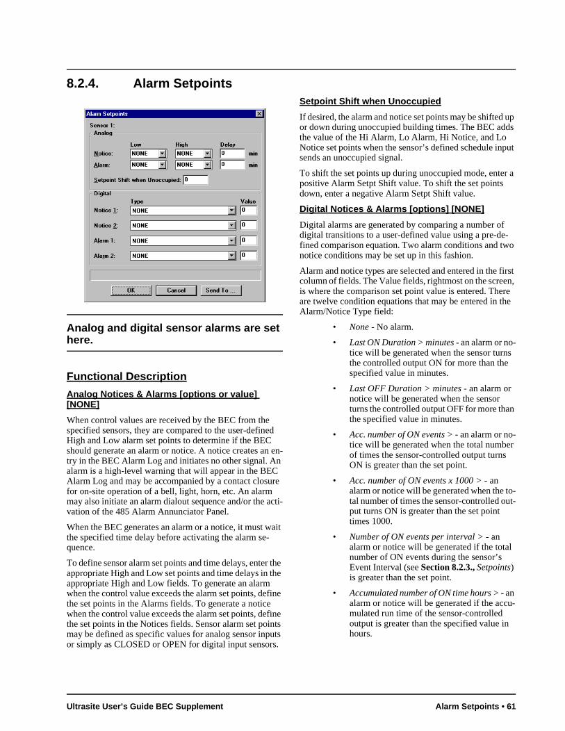
put
r a
-o
irst n, re e
s
n
r
o-t-
-
8.2.4. Alarm Setpoints
Analog and digital sensor alarms are set here.
Functional Description
Analog Notices & Alarms [options or value] [NONE]
When control values are received by the BEC from the specified sensors, they are compared to the user-defined High and Low alarm set points to determine if the BEC should generate an alarm or notice. A notice creates an en-try in the BEC Alarm Log and initiates no other signal. An alarm is a high-level warning that will appear in the BEC Alarm Log and may be accompanied by a contact closure for on-site operation of a bell, light, horn, etc. An alarm may also initiate an alarm dialout sequence and/or the acti-vation of the 485 Alarm Annunciator Panel.
When the BEC generates an alarm or a notice, it must wait the specified time delay before activating the alarm se-quence.
To define sensor alarm set points and time delays, enter the appropriate High and Low set points and time delays in the appropriate High and Low fields. To generate an alarm when the control value exceeds the alarm set points, define the set points in the Alarms fields. To generate a notice when the control value exceeds the alarm set points, define the set points in the Notices fields. Sensor alarm set points may be defined as specific values for analog sensor inputs or simply as CLOSED or OPEN for digital input sensors.
Setpoint Shift when Unoccupied
If desired, the alarm and notice set points may be shifted up or down during unoccupied building times. The BEC adds the value of the Hi Alarm, Lo Alarm, Hi Notice, and Lo Notice set points when the sensor’s defined schedule insends an unoccupied signal.
To shift the set points up during unoccupied mode, entepositive Alarm Setpt Shift value. To shift the set points down, enter a negative Alarm Setpt Shift value.
Digital Notices & Alarms [options] [NONE]
Digital alarms are generated by comparing a number ofdigital transitions to a user-defined value using a pre-defined comparison equation. Two alarm conditions and twnotice conditions may be set up in this fashion.
Alarm and notice types are selected and entered in the fcolumn of fields. The Value fields, rightmost on the screeis where the comparison set point value is entered. Theare twelve condition equations that may be entered in thAlarm/Notice Type field:
• None - No alarm.
• Last ON Duration > minutes - an alarm or no-tice will be generated when the sensor turnthe controlled output ON for more than the specified value in minutes.
• Last OFF Duration > minutes - an alarm or notice will be generated when the sensor turns the controlled output OFF for more thathe specified value in minutes.
• Acc. number of ON events > - an alarm or no-tice will be generated when the total numbeof times the sensor-controlled output turns ON is greater than the set point.
• Acc. number of ON events x 1000 > - an alarm or notice will be generated when the ttal number of times the sensor-controlled ouput turns ON is greater than the set point times 1000.
• Number of ON events per interval > - an alarm or notice will be generated if the totalnumber of ON events during the sensor’s Event Interval (see Section 8.2.3., Setpoints) is greater than the set point.
• Accumulated number of ON time hours > - an alarm or notice will be generated if the accumulated run time of the sensor-controlled output is greater than the specified value inhours.
Ultrasite User’s Guide BEC Supplement Alarm Setpoints • 61
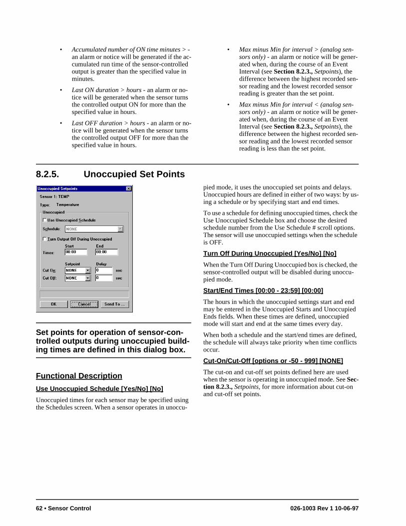
n-
n-
s. s-
the s. ule
e -
d ed
ed, s
• Accumulated number of ON time minutes > - an alarm or notice will be generated if the ac-cumulated run time of the sensor-controlled output is greater than the specified value in minutes.
• Last ON duration > hours - an alarm or no-tice will be generated when the sensor turns the controlled output ON for more than the specified value in hours.
• Last OFF duration > hours - an alarm or no-tice will be generated when the sensor turns the controlled output OFF for more than the specified value in hours.
• Max minus Min for interval > (analog sen-sors only) - an alarm or notice will be gener-ated when, during the course of an Event Interval (see Section 8.2.3., Setpoints), the difference between the highest recorded sesor reading and the lowest recorded sensorreading is greater than the set point.
• Max minus Min for interval < (analog sen-sors only) - an alarm or notice will be gener-ated when, during the course of an Event Interval (see Section 8.2.3., Setpoints), the difference between the highest recorded sesor reading and the lowest recorded sensorreading is less than the set point.
8.2.5. Unoccupied Set Points
Set points for operation of sensor-con-trolled outputs during unoccupied build-ing times are defined in this dialog box.
Functional Description
Use Unoccupied Schedule [Yes/No] [No]
Unoccupied times for each sensor may be specified using the Schedules screen. When a sensor operates in unoccu-
pied mode, it uses the unoccupied set points and delayUnoccupied hours are defined in either of two ways: by uing a schedule or by specifying start and end times.
To use a schedule for defining unoccupied times, check Use Unoccupied Schedule box and choose the desiredschedule number from the Use Schedule # scroll optionThe sensor will use unoccupied settings when the schedis OFF.
Turn Off During Unoccupied [Yes/No] [No]
When the Turn Off During Unoccupied box is checked, thsensor-controlled output will be disabled during unoccupied mode.
Start/End Times [00:00 - 23:59] [00:00]
The hours in which the unoccupied settings start and enmay be entered in the Unoccupied Starts and UnoccupiEnds fields. When these times are defined, unoccupiedmode will start and end at the same times every day.
When both a schedule and the start/end times are definthe schedule will always take priority when time conflictoccur.
Cut-On/Cut-Off [options or -50 - 999] [NONE]
The cut-on and cut-off set points defined here are usedwhen the sensor is operating in unoccupied mode. See Sec-tion 8.2.3., Setpoints, for more information about cut-on and cut-off set points.
62 • Sensor Control 026-1003 Rev 1 10-06-97
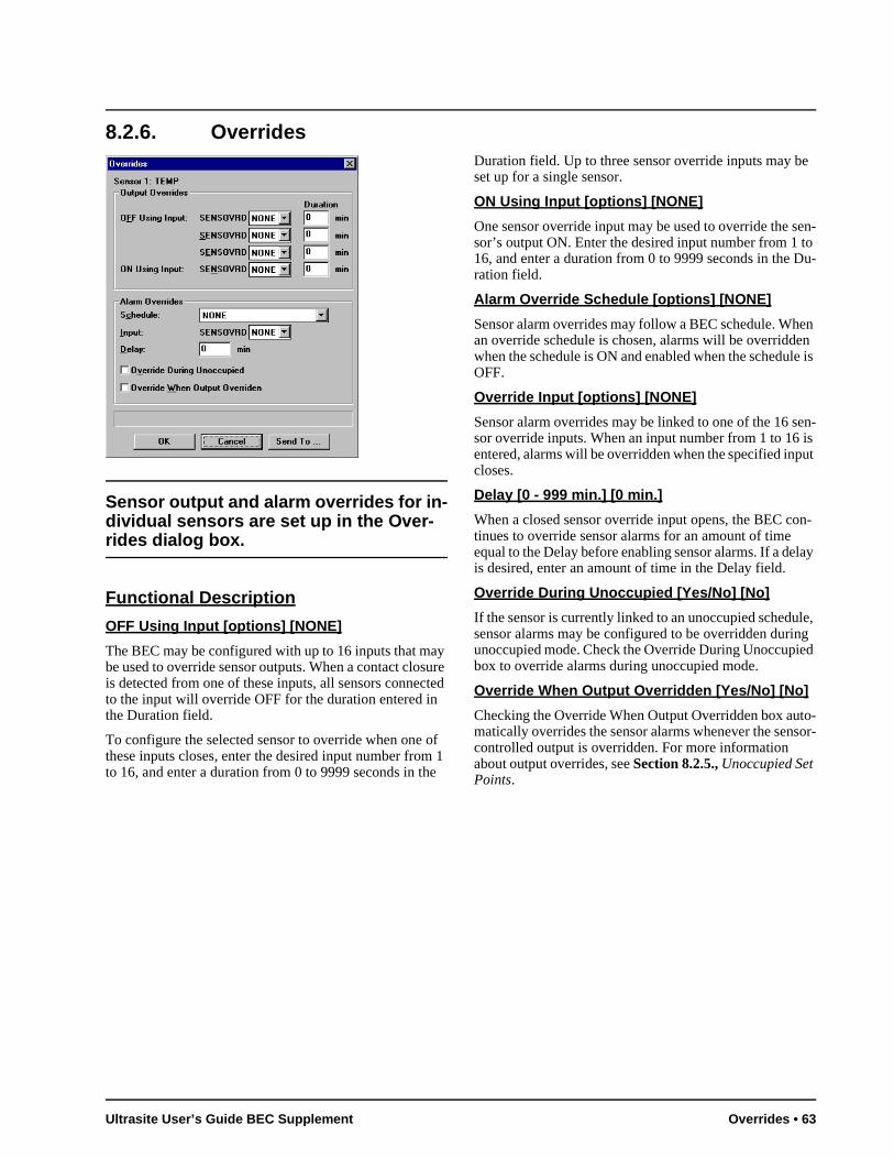
to Du-
en n
le is
en- is ut
n-
lay
le, g
ed
to-sor-
8.2.6. Overrides
Sensor output and alarm overrides for in-dividual sensors are set up in the Over-rides dialog box.
Functional Description
OFF Using Input [options] [NONE]
The BEC may be configured with up to 16 inputs that may be used to override sensor outputs. When a contact closure is detected from one of these inputs, all sensors connected to the input will override OFF for the duration entered in the Duration field.
To configure the selected sensor to override when one of these inputs closes, enter the desired input number from 1 to 16, and enter a duration from 0 to 9999 seconds in the
Duration field. Up to three sensor override inputs may be set up for a single sensor.
ON Using Input [options] [NONE]
One sensor override input may be used to override the sen-sor’s output ON. Enter the desired input number from 1 16, and enter a duration from 0 to 9999 seconds in the ration field.
Alarm Override Schedule [options] [NONE]
Sensor alarm overrides may follow a BEC schedule. Whan override schedule is chosen, alarms will be overriddewhen the schedule is ON and enabled when the scheduOFF.
Override Input [options] [NONE]
Sensor alarm overrides may be linked to one of the 16 ssor override inputs. When an input number from 1 to 16entered, alarms will be overridden when the specified inpcloses.
Delay [0 - 999 min.] [0 min.]
When a closed sensor override input opens, the BEC cotinues to override sensor alarms for an amount of time equal to the Delay before enabling sensor alarms. If a deis desired, enter an amount of time in the Delay field.
Override During Unoccupied [Yes/No] [No]
If the sensor is currently linked to an unoccupied schedusensor alarms may be configured to be overridden durinunoccupied mode. Check the Override During Unoccupibox to override alarms during unoccupied mode.
Override When Output Overridden [Yes/No] [No]
Checking the Override When Output Overridden box aumatically overrides the sensor alarms whenever the sencontrolled output is overridden. For more information about output overrides, see Section 8.2.5., Unoccupied Set Points.
Ultrasite User’s Guide BEC Supplement Overrides • 63
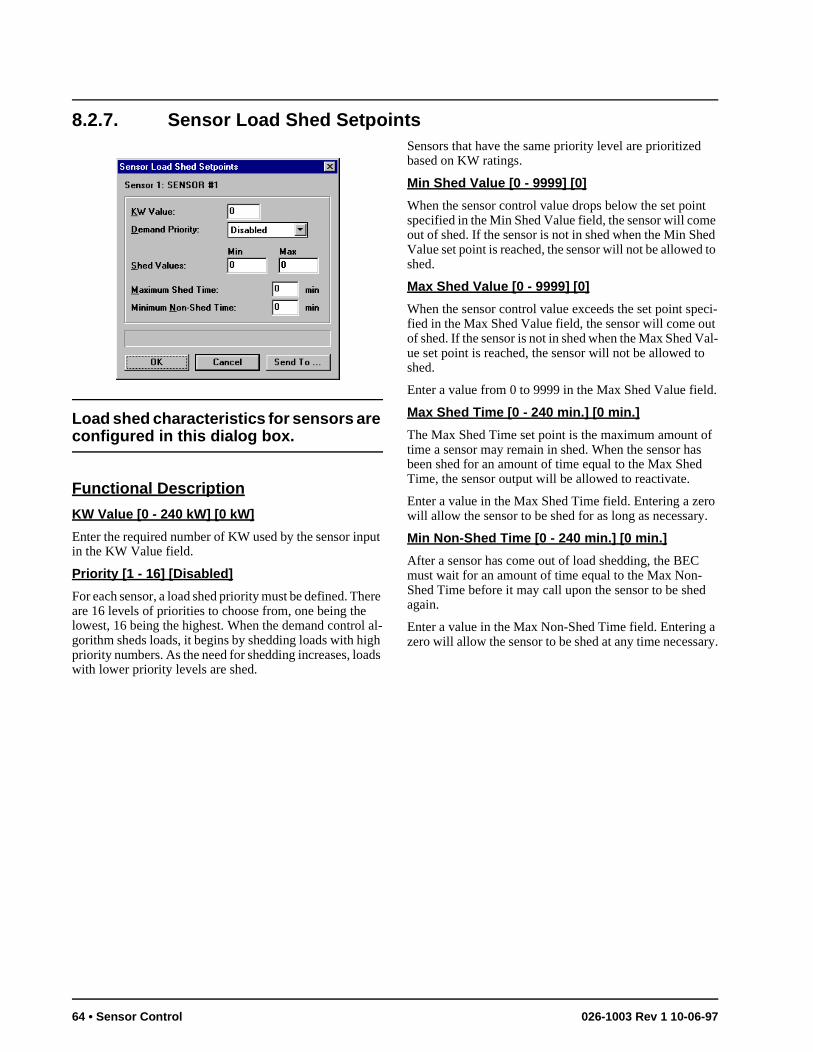
8.2.7. Sensor Load Shed Setpoints
Load shed characteristics for sensors are configured in this dialog box.
Functional Description
KW Value [0 - 240 kW] [0 kW]
Enter the required number of KW used by the sensor input in the KW Value field.
Priority [1 - 16] [Disabled]
For each sensor, a load shed priority must be defined. There are 16 levels of priorities to choose from, one being the lowest, 16 being the highest. When the demand control al-gorithm sheds loads, it begins by shedding loads with high priority numbers. As the need for shedding increases, loads with lower priority levels are shed.
Sensors that have the same priority level are prioritized based on KW ratings.
Min Shed Value [0 - 9999] [0]
When the sensor control value drops below the set point specified in the Min Shed Value field, the sensor will come out of shed. If the sensor is not in shed when the Min Shed Value set point is reached, the sensor will not be allowed to shed.
Max Shed Value [0 - 9999] [0]
When the sensor control value exceeds the set point speci-fied in the Max Shed Value field, the sensor will come out of shed. If the sensor is not in shed when the Max Shed Val-ue set point is reached, the sensor will not be allowed to shed.
Enter a value from 0 to 9999 in the Max Shed Value field.
Max Shed Time [0 - 240 min.] [0 min.]
The Max Shed Time set point is the maximum amount of time a sensor may remain in shed. When the sensor has been shed for an amount of time equal to the Max Shed Time, the sensor output will be allowed to reactivate.
Enter a value in the Max Shed Time field. Entering a zero will allow the sensor to be shed for as long as necessary.
Min Non-Shed Time [0 - 240 min.] [0 min.]
After a sensor has come out of load shedding, the BEC must wait for an amount of time equal to the Max Non-Shed Time before it may call upon the sensor to be shed again.
Enter a value in the Max Non-Shed Time field. Entering a zero will allow the sensor to be shed at any time necessary.
64 • Sensor Control 026-1003 Rev 1 10-06-97
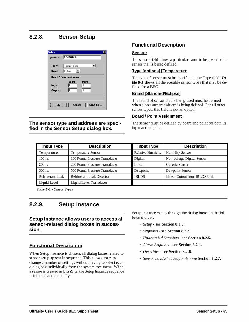
8.2.8. Sensor Setup
The sensor type and address are speci-fied in the Sensor Setup dialog box.
Functional Description
Sensor:
The sensor field allows a particular name to be given to the sensor that is being defined.
Type [options] [Temperature
The type of sensor must be specified in the Type field. Ta-ble 8-1 shows all the possible sensor types that may be de-fined for a BEC.
Brand [Standard/Eclipse]
The brand of sensor that is being used must be defined when a pressure transducer is being defined. For all other sensor types, this field is not an option.
Board / Point Assignment
The sensor must be defined by board and point for both its input and output.
8.2.9. Setup Instance
Setup Instance allows users to access all sensor-related dialog boxes in succes-sion.
Functional Description
When Setup Instance is chosen, all dialog boxes related to sensor setup appear in sequence. This allows users to change a number of settings without having to select each dialog box individually from the system tree menu. When a sensor is created in UltraSite, the Setup Instance sequence is initiated automatically.
Setup Instance cycles through the dialog boxes in the fol-lowing order:
• Setup - see Section 8.2.8.
• Setpoints - see Section 8.2.3.
• Unoccupied Setpoints - see Section 8.2.5.
• Alarm Setpoints - see Section 8.2.4.
• Overrides - see Section 8.2.6.
• Sensor Load Shed Setpoints - see Section 8.2.7.
Input Type Description Input Type Description
Temperature Temperature Sensor Relative Humidity Humidity Sensor
100 lb. 100 Pound Pressure Transducer Digital Non-voltage Digital Sensor
200 lb 200 Pound Pressure Transducer Linear Generic Sensor
500 lb. 500 Pound Pressure Transducer Dewpoint Dewpoint Sensor
Refrigerant Leak Refrigerant Leak Detector IRLDS Linear Output from IRLDS Unit
Liquid Level Liquid Level Transducer
Table 8-1 - Sensor Types
Ultrasite User’s Guide BEC Supplement Sensor Setup • 65
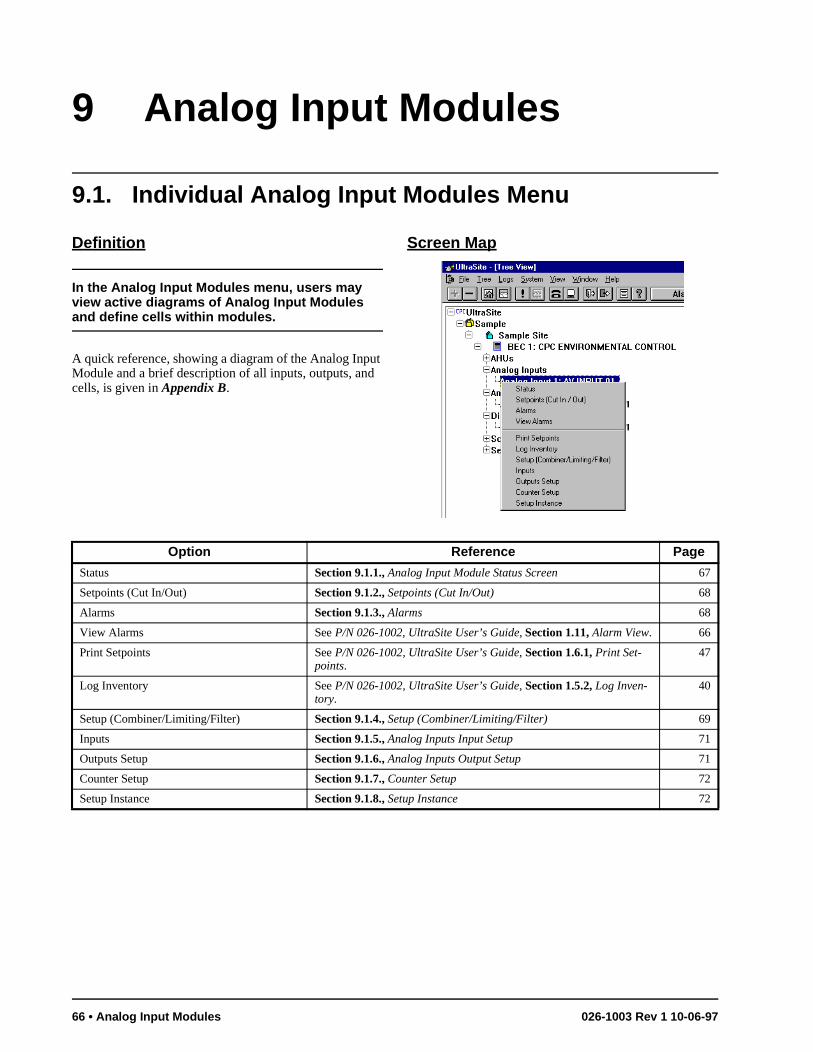
9 Analog Input Modules
9.1. Individual Analog Input Modules Menu
Definition
In the Analog Input Modules menu, users may view active diagrams of Analog Input Modules and define cells within modules.
A quick reference, showing a diagram of the Analog Input Module and a brief description of all inputs, outputs, and cells, is given in Appendix B.
Screen Map
Option Reference Page
Status Section 9.1.1., Analog Input Module Status Screen 67
Setpoints (Cut In/Out) Section 9.1.2., Setpoints (Cut In/Out) 68
Alarms Section 9.1.3., Alarms 68
View Alarms See P/N 026-1002, UltraSite User’s Guide, Section 1.11, Alarm View. 66
Print Setpoints See P/N 026-1002, UltraSite User’s Guide, Section 1.6.1, Print Set-points.
47
Log Inventory See P/N 026-1002, UltraSite User’s Guide, Section 1.5.2, Log Inven-tory.
40
Setup (Combiner/Limiting/Filter) Section 9.1.4., Setup (Combiner/Limiting/Filter) 69
Inputs Section 9.1.5., Analog Inputs Input Setup 71
Outputs Setup Section 9.1.6., Analog Inputs Output Setup 71
Counter Setup Section 9.1.7., Counter Setup 72
Setup Instance Section 9.1.8., Setup Instance 72
66 • Analog Input Modules 026-1003 Rev 1 10-06-97
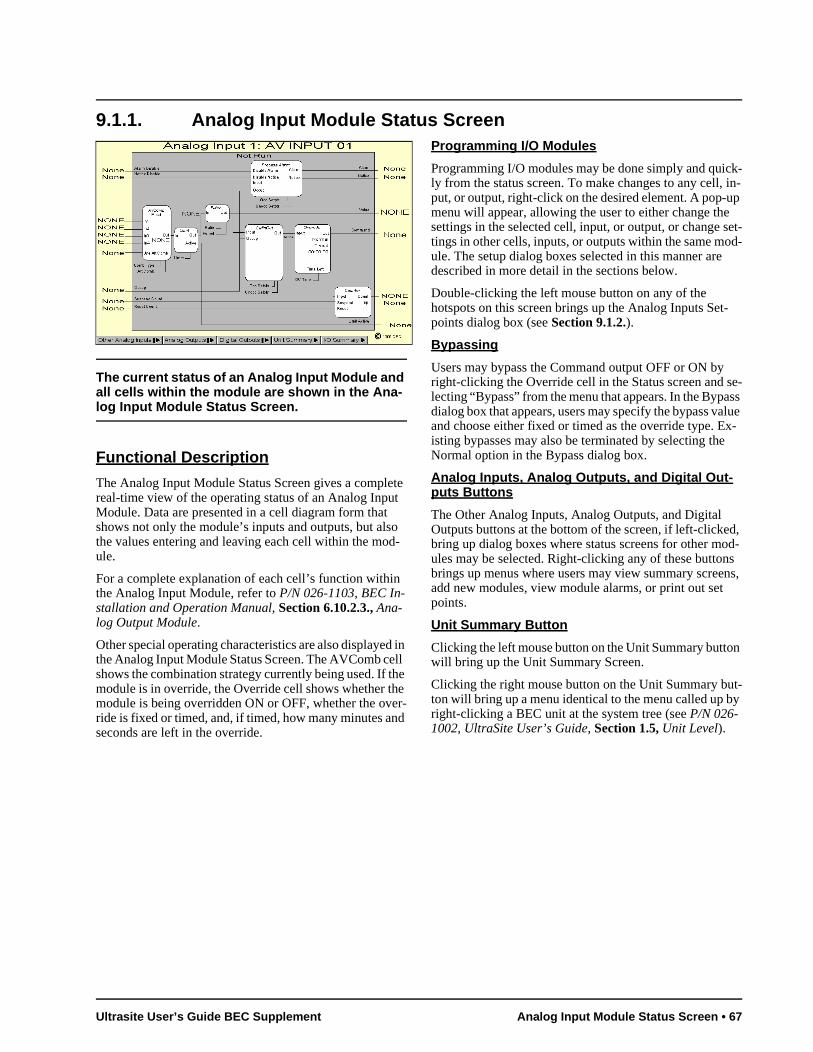
k- in-p
set-d-
-
se-ss lue
x-
d, od-s ns,
y
9.1.1. Analog Input Module Status Screen
The current status of an Analog Input Module and all cells within the module are shown in the Ana-log Input Module Status Screen.
Functional Description
The Analog Input Module Status Screen gives a complete real-time view of the operating status of an Analog Input Module. Data are presented in a cell diagram form that shows not only the module’s inputs and outputs, but also the values entering and leaving each cell within the mod-ule.
For a complete explanation of each cell’s function within the Analog Input Module, refer to P/N 026-1103, BEC In-stallation and Operation Manual, Section 6.10.2.3., Ana-log Output Module.
Other special operating characteristics are also displayed in the Analog Input Module Status Screen. The AVComb cell shows the combination strategy currently being used. If the module is in override, the Override cell shows whether the module is being overridden ON or OFF, whether the over-ride is fixed or timed, and, if timed, how many minutes and seconds are left in the override.
Programming I/O Modules
Programming I/O modules may be done simply and quicly from the status screen. To make changes to any cell,put, or output, right-click on the desired element. A pop-umenu will appear, allowing the user to either change thesettings in the selected cell, input, or output, or change tings in other cells, inputs, or outputs within the same moule. The setup dialog boxes selected in this manner aredescribed in more detail in the sections below.
Double-clicking the left mouse button on any of the hotspots on this screen brings up the Analog Inputs Setpoints dialog box (see Section 9.1.2.).
Bypassing
Users may bypass the Command output OFF or ON byright-clicking the Override cell in the Status screen and lecting “Bypass” from the menu that appears. In the Bypadialog box that appears, users may specify the bypass vaand choose either fixed or timed as the override type. Eisting bypasses may also be terminated by selecting theNormal option in the Bypass dialog box.
Analog Inputs, Analog Outputs, and Digital Out-puts Buttons
The Other Analog Inputs, Analog Outputs, and Digital Outputs buttons at the bottom of the screen, if left-clickebring up dialog boxes where status screens for other mules may be selected. Right-clicking any of these buttonbrings up menus where users may view summary screeadd new modules, view module alarms, or print out set points.
Unit Summary Button
Clicking the left mouse button on the Unit Summary button will bring up the Unit Summary Screen.
Clicking the right mouse button on the Unit Summary but-ton will bring up a menu identical to the menu called up bright-clicking a BEC unit at the system tree (see P/N 026-1002, UltraSite User’s Guide, Section 1.5, Unit Level).
Ultrasite User’s Guide BEC Supplement Analog Input Module Status Screen • 67
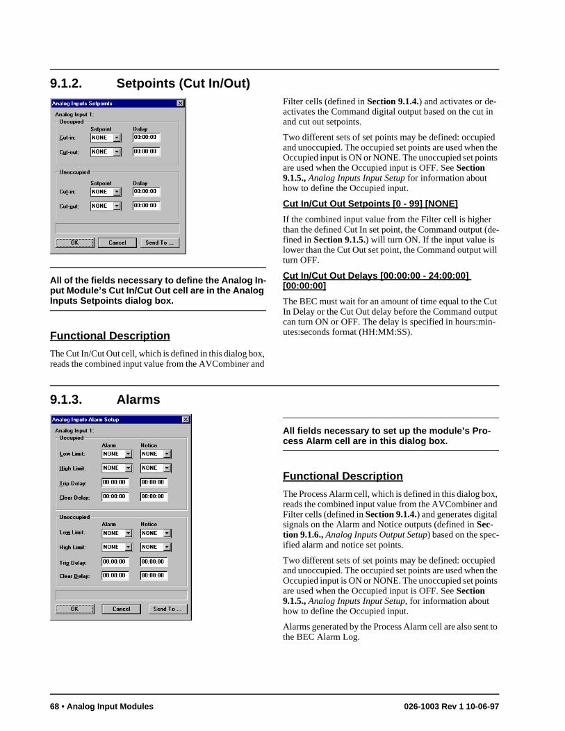
9.1.2. Setpoints (Cut In/Out)
All of the fields necessary to define the Analog In-put Module’s Cut In/Cut Out cell are in the Analog Inputs Setpoints dialog box.
Functional Description
The Cut In/Cut Out cell, which is defined in this dialog box, reads the combined input value from the AVCombiner and
Filter cells (defined in Section 9.1.4.) and activates or de-activates the Command digital output based on the cut in and cut out setpoints.
Two different sets of set points may be defined: occupied and unoccupied. The occupied set points are used when the Occupied input is ON or NONE. The unoccupied set points are used when the Occupied input is OFF. See Section 9.1.5., Analog Inputs Input Setup for information about how to define the Occupied input.
Cut In/Cut Out Setpoints [0 - 99] [NONE]
If the combined input value from the Filter cell is higher than the defined Cut In set point, the Command output (de-fined in Section 9.1.5.) will turn ON. If the input value is lower than the Cut Out set point, the Command output will turn OFF.
Cut In/Cut Out Delays [00:00:00 - 24:00:00] [00:00:00]
The BEC must wait for an amount of time equal to the Cut In Delay or the Cut Out delay before the Command output can turn ON or OFF. The delay is specified in hours:min-utes:seconds format (HH:MM:SS).
9.1.3. Alarms
All fields necessary to set up the module’s Pro-cess Alarm cell are in this dialog box.
Functional Description
The Process Alarm cell, which is defined in this dialog box, reads the combined input value from the AVCombiner and Filter cells (defined in Section 9.1.4.) and generates digital signals on the Alarm and Notice outputs (defined in Sec-tion 9.1.6., Analog Inputs Output Setup) based on the spec-ified alarm and notice set points.
Two different sets of set points may be defined: occupied and unoccupied. The occupied set points are used when the Occupied input is ON or NONE. The unoccupied set points are used when the Occupied input is OFF. See Section 9.1.5., Analog Inputs Input Setup, for information about how to define the Occupied input.
Alarms generated by the Process Alarm cell are also sent to the BEC Alarm Log.
68 • Analog Input Modules 026-1003 Rev 1 10-06-97
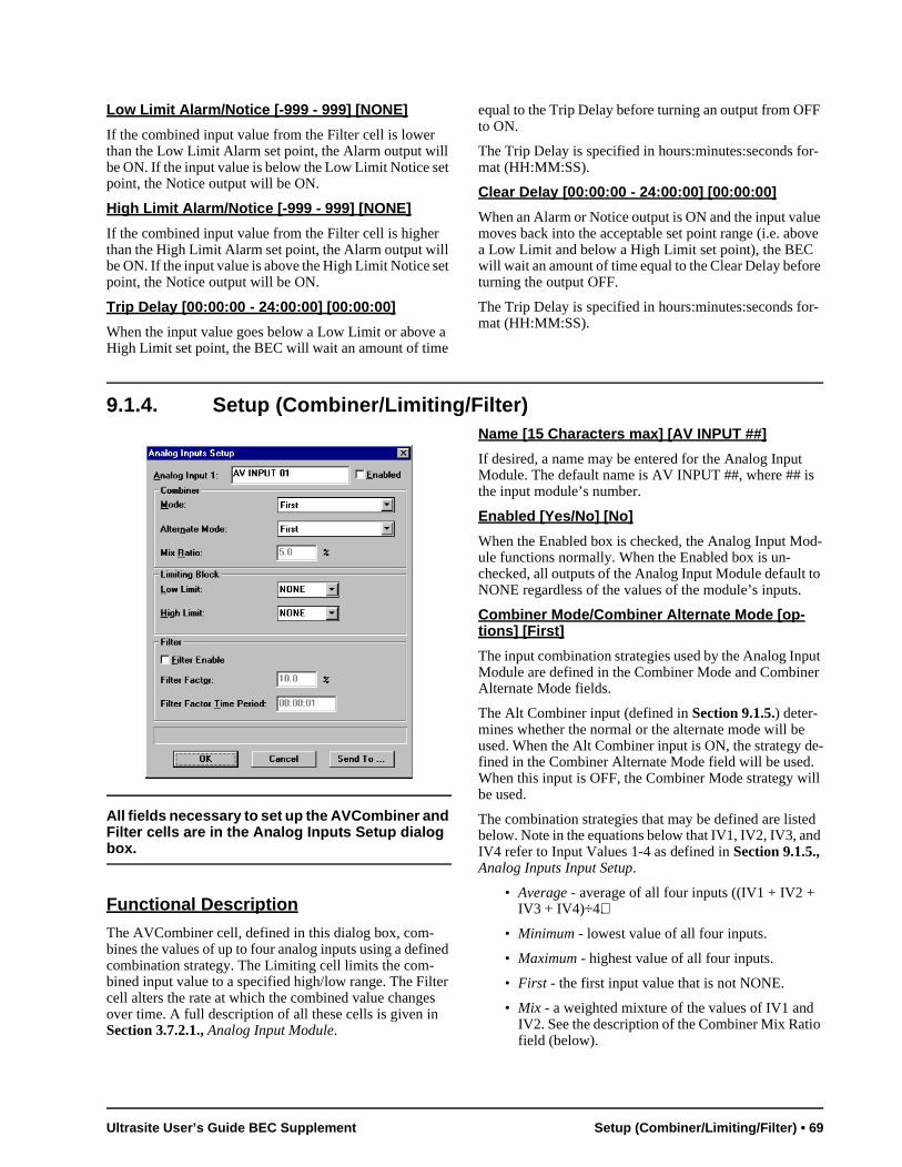
d-
to
ut er
e-
ill
d d
Low Limit Alarm/Notice [-999 - 999] [NONE]
If the combined input value from the Filter cell is lower than the Low Limit Alarm set point, the Alarm output will be ON. If the input value is below the Low Limit Notice set point, the Notice output will be ON.
High Limit Alarm/Notice [-999 - 999] [NONE]
If the combined input value from the Filter cell is higher than the High Limit Alarm set point, the Alarm output will be ON. If the input value is above the High Limit Notice set point, the Notice output will be ON.
Trip Delay [00:00:00 - 24:00:00] [00:00:00]
When the input value goes below a Low Limit or above a High Limit set point, the BEC will wait an amount of time
equal to the Trip Delay before turning an output from OFF to ON.
The Trip Delay is specified in hours:minutes:seconds for-mat (HH:MM:SS).
Clear Delay [00:00:00 - 24:00:00] [00:00:00]
When an Alarm or Notice output is ON and the input value moves back into the acceptable set point range (i.e. above a Low Limit and below a High Limit set point), the BEC will wait an amount of time equal to the Clear Delay before turning the output OFF.
The Trip Delay is specified in hours:minutes:seconds for-mat (HH:MM:SS).
9.1.4. Setup (Combiner/Limiting/Filter)
All fields necessary to set up the AVCombiner and Filter cells are in the Analog Inputs Setup dialog box.
Functional Description
The AVCombiner cell, defined in this dialog box, com-bines the values of up to four analog inputs using a defined combination strategy. The Limiting cell limits the com-bined input value to a specified high/low range. The Filter cell alters the rate at which the combined value changes over time. A full description of all these cells is given in Section 3.7.2.1., Analog Input Module.
Name [15 Characters max] [AV INPUT ##]
If desired, a name may be entered for the Analog Input Module. The default name is AV INPUT ##, where ## is the input module’s number.
Enabled [Yes/No] [No]
When the Enabled box is checked, the Analog Input Moule functions normally. When the Enabled box is un-checked, all outputs of the Analog Input Module default NONE regardless of the values of the module’s inputs.
Combiner Mode/Combiner Alternate Mode [op-tions] [First]
The input combination strategies used by the Analog InpModule are defined in the Combiner Mode and CombinAlternate Mode fields.
The Alt Combiner input (defined in Section 9.1.5.) deter-mines whether the normal or the alternate mode will beused. When the Alt Combiner input is ON, the strategy dfined in the Combiner Alternate Mode field will be used.When this input is OFF, the Combiner Mode strategy wbe used.
The combination strategies that may be defined are listebelow. Note in the equations below that IV1, IV2, IV3, anIV4 refer to Input Values 1-4 as defined in Section 9.1.5., Analog Inputs Input Setup.
• Average - average of all four inputs ((IV1 + IV2 + IV3 + IV4)÷4).
• Minimum - lowest value of all four inputs.
• Maximum - highest value of all four inputs.
• First - the first input value that is not NONE.
• Mix - a weighted mixture of the values of IV1 and IV2. See the description of the Combiner Mix Ratiofield (below).
Ultrasite User’s Guide BEC Supplement Setup (Combiner/Limiting/Filter) • 69

g the
g
lar s re-e ut-
e , he ur-s ut
in e e, he as ut
s ut
ut put e-
• Add - the first three inputs added together (IV1 + IV2 + IV3).
• Subtract - the first three inputs subtracted from each other (IV1 - IV2 - IV3).
• Multiply - the first three inputs multiplied together (IV1 * IV2 * IV3).
• Divide - the first two inputs divided by the third ((IV1 + IV2) ÷ IV3).
• Multiply/Add - The first two inputs multiplied to-gether and added to the third ((IV1 * IV2) + IV3).
• Subtract/Mult - The first two inputs subtracted from each other and multiplied with the third ((IV1 - IV2) * IV3).
• Abs/Divide - The absolute value of (IV1 - IV2) ÷ IV3.
• Abs/Mult - The absolute value of (IV1 - IV2) * IV3.
• Square Root - The square root of the absolute value of IV1 - IV2, multiplied by IV3 (sqr( |IV1 - IV2| ) * IV3).
• Span-The difference between IV1 and IV2 (IV1-IV2).
Combiner Mix Ratio [0 - 100%] [5.0%]
The Combiner Mix Ratio field is highlighted only if the Mix strategy is defined in either the Combiner Mode or Combiner Alternate Mode fields.
The Mix strategy takes a certain percentage of Input Value 1 and adds it to a certain percentage of Input Value 2. The Combiner Mix Ratio determines what percentages are ap-plied to the input values.
The percentage entered in the Combiner Mix Ratio is ap-plied directly to Input 1. The percentage applied to Input 2 is equal to 100% minus the Combiner Mix Ratio field. Thus, if the Combiner Mix Ratio were 60%, the Mix strat-egy would take 60% of Input 1 and add it to 40% of Input 2. Likewise, if the Combiner Mix Ratio were 25%, the out-put would be 25% of Input 1 and 75% of Input 2.
Limiting Block Low Limit[-999 to 999 or NONE] [NONE]
The Limiting Block Low Limit is the lowest limit of the combined value from the AVCombiner cell. If the com-bined input value is lower than this set point, the Limiting cell blocks the value from being passed on to the rest of the
module, and instead passes on the Limiting Block Low Limit set point value.
Limiting Block High Limit[-999 to 999 or NONE] [NONE]
The Limiting Block High Limit is the highest limit of the combined value from the AVCombiner cell. If the com-bined input value is higher than this set point, the Limitincell blocks the value from being passed on to the rest of module, and instead passes on the Limiting Block High Limit set point value.
Filter Enable [Yes/No] [No]
The Filter Enable box enables the Filter cell. If no filterinis desired, uncheck this box; if filtering is desired, checkthis box.
Filter Factor [0% - 100%] [10%]
The Filter cell samples the combined input values at regutime intervals (defined in Filter Period below). This allowthe Filter cell to compare newly sampled values to the pviously sampled values and adjust the cell’s output valuaccordingly. The amount the Filter cell adjusts the cell oput is entered in the Filter Factor field.
Simply put, the Filter cell subtracts the output value of thprevious sampling period from the newly sampled valueand to this value it applies the Filter Factor percentage. Tresulting value is the amount the Filter cell adds to the crent Filter cell output. In this manner, the Filter cell slowthe output’s reaction time to changes in the combined inpvalue.
For example, suppose a combined input value suddenlychanges from 50 to 60. If a Filter Factor of 50% is active this module, only half of that change will be reflected in thFilter cell output during a single sample period. Thereforwhen the input change is first detected by the Filter cell, toutput would immediately go to 55. Note, however, that long as the input value remains at 60, the Filter cell’s outpwill eventually climb to 60 after several sampling period(going from 55 to 57.5 to 58.75 and so on until the outpeventually reaches 60).
Filter Time Period [00:00:00 - 24:00:00] [00:00:01]
The Filter Time Period is the amount of time between inpsamples and output changes. The Filter cell reads the invalue, adjusts the output value as described above, andwaits an amount of time equal to the Filter Time Period bfore repeating the process.
70 • Analog Input Modules 026-1003 Rev 1 10-06-97
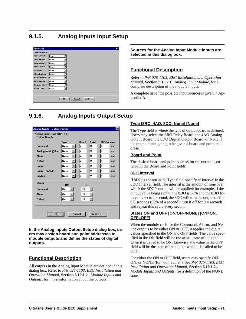
e In-or s,
o-l ec- F
9.1.5. Analog Inputs Input Setup
Sources for the Analog Input Module inputs are selected in this dialog box.
Functional Description
Refer to P/N 026-1103, BEC Installation and Operation Manual, Section 6.10.2.1., Analog Input Module, for a complete description of the module inputs.
A complete list of the possible input sources is given in Ap-pendix A.
9.1.6. Analog Inputs Output Setup
In the Analog Inputs Output Setup dialog box, us-ers may assign board and point addresses to module outputs and define the states of digital outputs.
Functional Description
All outputs in the Analog Input Module are defined in this dialog box. Refer to P/N 026-1103, BEC Installation and Operation Manual, Section 6.10.1.2., Module Inputs and Outputs, for more information about the outputs.
Type [8RO, 4AO, 8DO, None] [None]
The Type field is where the type of output board is defined. Users may select the 8RO Relay Board, the 4AO Analog Output Board, the 8DO Digital Output Board, or None if the output is not going to be given a board and point ad-dress.
Board and Point
The desired board and point address for the output is en-tered in the Board and Point fields.
8DO Interval
If 8DO is chosen in the Type field, specify an interval in the 8DO Interval field. The interval is the amount of time over which the 8DO’s output will be applied; for example, if thoutput value being sent to the 8DO is 60% and the 8DOterval is set to 1 second, the 8DO will turn the output on f0.6 seconds (60% of a second), turn it off for 0.4 secondand repeat this cycle every second.
States ON and OFF [ON/OFF/NONE] [ON=ON, OFF=OFF]
When the module calls for the Command, Alarm, and Ntice outputs to be either ON or OFF, it applies the digitavalues specified in the ON and OFF fields. The value spified in the ON field will be the actual state of the outputwhen it is called to be ON. Likewise, the value in the OFfield will be the state of the output when it is called to beOFF.
For either the ON or OFF field, users may specify OFF,ON, or NONE (for “don’t care”). See P/N 026-1103, BEC Installation and Operation Manual, Section 6.10.1.2., Module Inputs and Outputs, for a definition of the NONE state.
Ultrasite User’s Guide BEC Supplement Analog Inputs Input Setup • 71
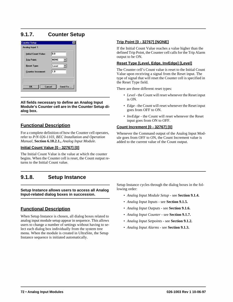
nt in
t
t
d-
l-
9.1.7. Counter Setup
All fields necessary to define an Analog Input Module’s Counter cell are in the Counter Setup di-alog box.
Functional Description
For a complete definition of how the Counter cell operates, refer to P/N 026-1103, BEC Installation and Operation Manual, Section 6.10.2.1., Analog Input Module.
Initial Count Value [0 - 32767] [0]
The Initial Count Value is the value at which the counter begins. When the Counter cell is reset, the Count output re-turns to the Initial Count value.
Trip Point [0 - 32767] [NONE]
If the Initial Count Value reaches a value higher than the defined Trip Point, the Counter cell calls for the Trip Alarm output to be ON.
Reset Type [Level, Edge, InvEdge] [Level]
The Counter cell’s Count value is reset to the Initial CouValue upon receiving a signal from the Reset input. Thetype of signal that will reset the Counter cell is specified the Reset Type field.
There are three different reset types:
• Level - the Count will reset whenever the Reset inpuis ON.
• Edge - the Count will reset whenever the Reset inpugoes from OFF to ON.
• InvEdge - the Count will reset whenever the Resetinput goes from ON to OFF.
Count Increment [0 - 32767] [0]
Whenever the Command output of the Analog Input Moule goes from OFF to ON, the Count Increment value isadded to the current value of the Count output.
9.1.8. Setup Instance
Setup Instance allows users to access all Analog Input-related dialog boxes in succession.
Functional Description
When Setup Instance is chosen, all dialog boxes related to analog input module setup appear in sequence. This allows users to change a number of settings without having to se-lect each dialog box individually from the system tree menu. When the module is created in UltraSite, the Setup Instance sequence is initiated automatically.
Setup Instance cycles through the dialog boxes in the folowing order:
• Analog Input Module Setup - see Section 9.1.4.
• Analog Input Inputs - see Section 9.1.5.
• Analog Input Outputs - see Section 9.1.6.
• Analog Input Counter - see Section 9.1.7.
• Analog Input Setpoints - see Section 9.1.2.
• Analog Input Alarms - see Section 9.1.3.
72 • Analog Input Modules 026-1003 Rev 1 10-06-97
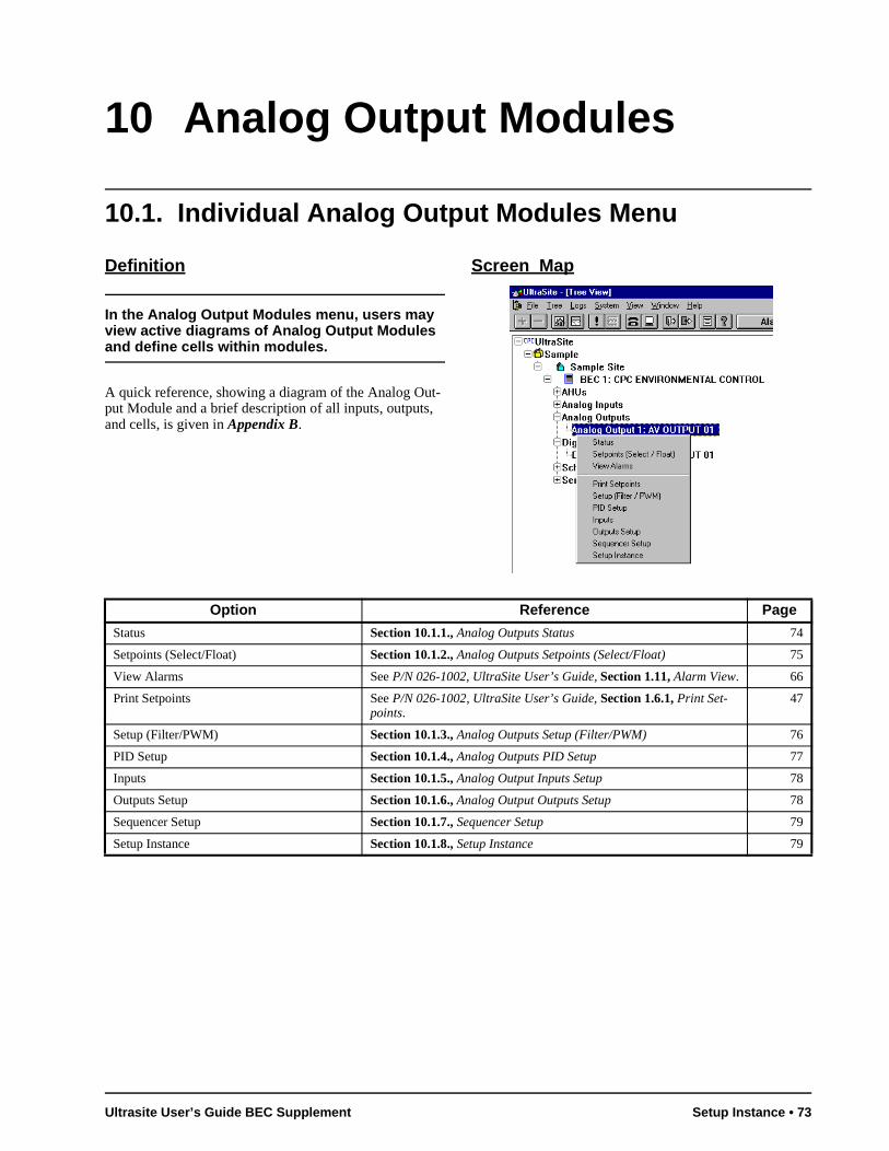
10 Analog Output Modules
10.1. Individual Analog Output Modules Menu
Definition
In the Analog Output Modules menu, users may view active diagrams of Analog Output Modules and define cells within modules.
A quick reference, showing a diagram of the Analog Out-put Module and a brief description of all inputs, outputs, and cells, is given in Appendix B.
Screen Map
Option Reference Page
Status Section 10.1.1., Analog Outputs Status 74
Setpoints (Select/Float) Section 10.1.2., Analog Outputs Setpoints (Select/Float) 75
View Alarms See P/N 026-1002, UltraSite User’s Guide, Section 1.11, Alarm View. 66
Print Setpoints See P/N 026-1002, UltraSite User’s Guide, Section 1.6.1, Print Set-points.
47
Setup (Filter/PWM) Section 10.1.3., Analog Outputs Setup (Filter/PWM) 76
PID Setup Section 10.1.4., Analog Outputs PID Setup 77
Inputs Section 10.1.5., Analog Output Inputs Setup 78
Outputs Setup Section 10.1.6., Analog Output Outputs Setup 78
Sequencer Setup Section 10.1.7., Sequencer Setup 79
Setup Instance Section 10.1.8., Setup Instance 79
Ultrasite User’s Guide BEC Supplement Setup Instance • 73
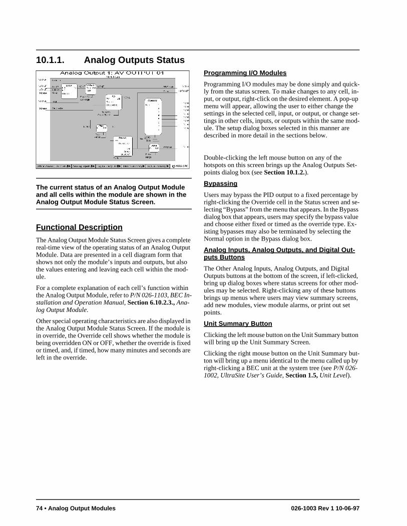
k- in-p
set-d-
et-
by se-ss lue
x-
d, od-s ns,
y
10.1.1. Analog Outputs Status
The current status of an Analog Output Module and all cells within the module are shown in the Analog Output Module Status Screen.
Functional Description
The Analog Output Module Status Screen gives a complete real-time view of the operating status of an Analog Output Module. Data are presented in a cell diagram form that shows not only the module’s inputs and outputs, but also the values entering and leaving each cell within the mod-ule.
For a complete explanation of each cell’s function within the Analog Output Module, refer to P/N 026-1103, BEC In-stallation and Operation Manual, Section 6.10.2.3., Ana-log Output Module.
Other special operating characteristics are also displayed in the Analog Output Module Status Screen. If the module is in override, the Override cell shows whether the module is being overridden ON or OFF, whether the override is fixed or timed, and, if timed, how many minutes and seconds are left in the override.
Programming I/O Modules
Programming I/O modules may be done simply and quicly from the status screen. To make changes to any cell,put, or output, right-click on the desired element. A pop-umenu will appear, allowing the user to either change thesettings in the selected cell, input, or output, or change tings in other cells, inputs, or outputs within the same moule. The setup dialog boxes selected in this manner aredescribed in more detail in the sections below.
Double-clicking the left mouse button on any of the hotspots on this screen brings up the Analog Outputs Spoints dialog box (see Section 10.1.2.).
Bypassing
Users may bypass the PID output to a fixed percentageright-clicking the Override cell in the Status screen and lecting “Bypass” from the menu that appears. In the Bypadialog box that appears, users may specify the bypass vaand choose either fixed or timed as the override type. Eisting bypasses may also be terminated by selecting theNormal option in the Bypass dialog box.
Analog Inputs, Analog Outputs, and Digital Out-puts Buttons
The Other Analog Inputs, Analog Outputs, and Digital Outputs buttons at the bottom of the screen, if left-clickebring up dialog boxes where status screens for other mules may be selected. Right-clicking any of these buttonbrings up menus where users may view summary screeadd new modules, view module alarms, or print out set points.
Unit Summary Button
Clicking the left mouse button on the Unit Summary button will bring up the Unit Summary Screen.
Clicking the right mouse button on the Unit Summary but-ton will bring up a menu identical to the menu called up bright-clicking a BEC unit at the system tree (see P/N 026-1002, UltraSite User’s Guide, Section 1.5, Unit Level).
74 • Analog Output Modules 026-1003 Rev 1 10-06-97
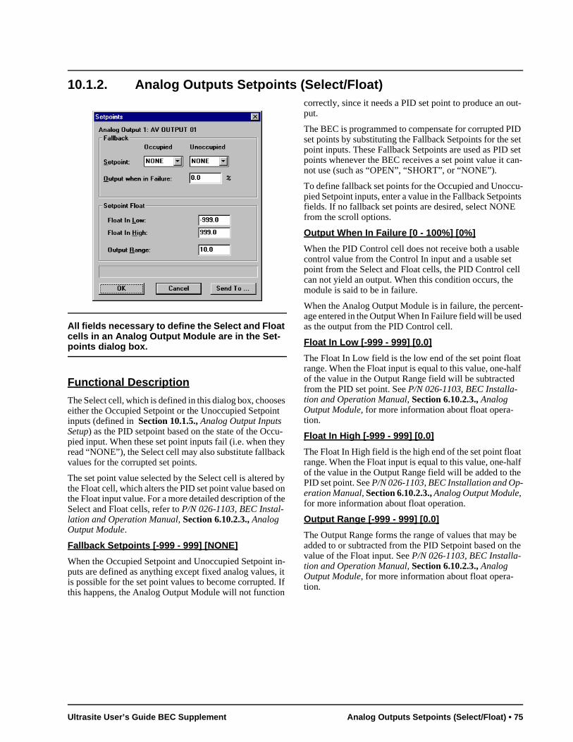
ut-
ID et
set an-
u-nts
le
ll
t-ed
t alf
t alf e
e the
10.1.2. Analog Outputs Setpoints (Select/Float)
All fields necessary to define the Select and Float cells in an Analog Output Module are in the Set-points dialog box.
Functional Description
The Select cell, which is defined in this dialog box, chooses either the Occupied Setpoint or the Unoccupied Setpoint inputs (defined in Section 10.1.5., Analog Output Inputs Setup) as the PID setpoint based on the state of the Occu-pied input. When these set point inputs fail (i.e. when they read “NONE”), the Select cell may also substitute fallback values for the corrupted set points.
The set point value selected by the Select cell is altered by the Float cell, which alters the PID set point value based on the Float input value. For a more detailed description of the Select and Float cells, refer to P/N 026-1103, BEC Instal-lation and Operation Manual, Section 6.10.2.3., Analog Output Module.
Fallback Setpoints [-999 - 999] [NONE]
When the Occupied Setpoint and Unoccupied Setpoint in-puts are defined as anything except fixed analog values, it is possible for the set point values to become corrupted. If this happens, the Analog Output Module will not function
correctly, since it needs a PID set point to produce an oput.
The BEC is programmed to compensate for corrupted Pset points by substituting the Fallback Setpoints for the spoint inputs. These Fallback Setpoints are used as PIDpoints whenever the BEC receives a set point value it cnot use (such as “OPEN”, “SHORT”, or “NONE”).
To define fallback set points for the Occupied and Unoccpied Setpoint inputs, enter a value in the Fallback Setpoifields. If no fallback set points are desired, select NONEfrom the scroll options.
Output When In Failure [0 - 100%] [0%]
When the PID Control cell does not receive both a usabcontrol value from the Control In input and a usable set point from the Select and Float cells, the PID Control cecan not yield an output. When this condition occurs, themodule is said to be in failure.
When the Analog Output Module is in failure, the percenage entered in the Output When In Failure field will be usas the output from the PID Control cell.
Float In Low [-999 - 999] [0.0]
The Float In Low field is the low end of the set point floarange. When the Float input is equal to this value, one-hof the value in the Output Range field will be subtractedfrom the PID set point. See P/N 026-1103, BEC Installa-tion and Operation Manual, Section 6.10.2.3., Analog Output Module, for more information about float opera-tion.
Float In High [-999 - 999] [0.0]
The Float In High field is the high end of the set point floarange. When the Float input is equal to this value, one-hof the value in the Output Range field will be added to thPID set point. See P/N 026-1103, BEC Installation and Op-eration Manual, Section 6.10.2.3., Analog Output Module, for more information about float operation.
Output Range [-999 - 999] [0.0]
The Output Range forms the range of values that may badded to or subtracted from the PID Setpoint based on value of the Float input. See P/N 026-1103, BEC Installa-tion and Operation Manual, Section 6.10.2.3., Analog Output Module, for more information about float opera-tion.
Ultrasite User’s Guide BEC Supplement Analog Outputs Setpoints (Select/Float) • 75
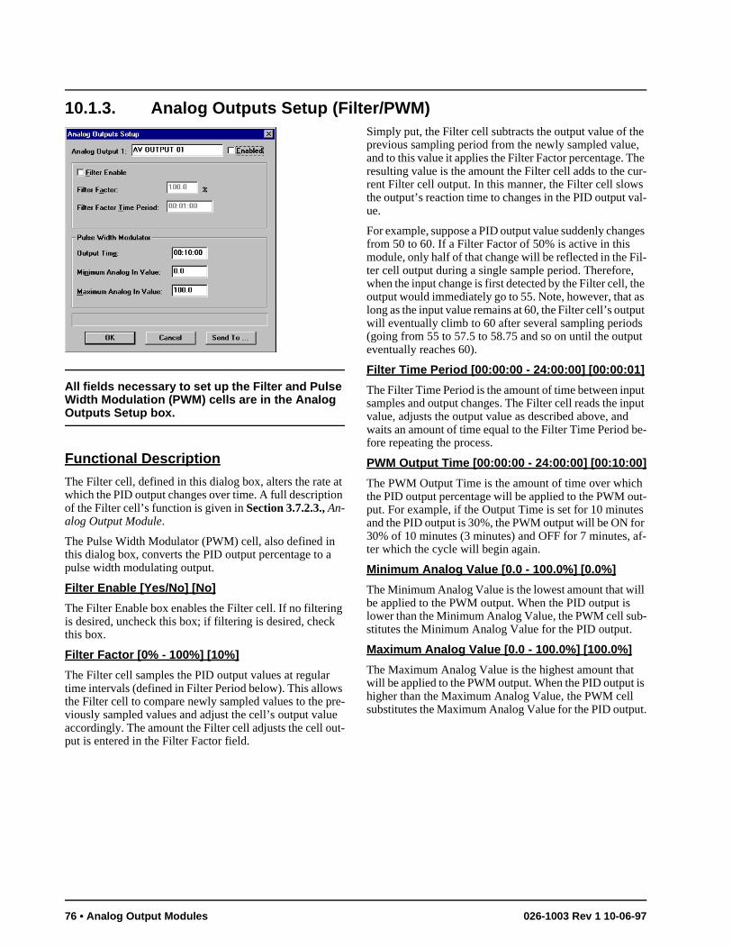
e , he ur-s al-
ges
il- he as ut
s ut
ut put e-
ut-s r af-
ll
-
is
t.
10.1.3. Analog Outputs Setup (Filter/PWM)
All fields necessary to set up the Filter and Pulse Width Modulation (PWM) cells are in the Analog Outputs Setup box.
Functional Description
The Filter cell, defined in this dialog box, alters the rate at which the PID output changes over time. A full description of the Filter cell’s function is given in Section 3.7.2.3., An-alog Output Module.
The Pulse Width Modulator (PWM) cell, also defined in this dialog box, converts the PID output percentage to a pulse width modulating output.
Filter Enable [Yes/No] [No]
The Filter Enable box enables the Filter cell. If no filtering is desired, uncheck this box; if filtering is desired, check this box.
Filter Factor [0% - 100%] [10%]
The Filter cell samples the PID output values at regular time intervals (defined in Filter Period below). This allows the Filter cell to compare newly sampled values to the pre-viously sampled values and adjust the cell’s output value accordingly. The amount the Filter cell adjusts the cell out-put is entered in the Filter Factor field.
Simply put, the Filter cell subtracts the output value of thprevious sampling period from the newly sampled valueand to this value it applies the Filter Factor percentage. Tresulting value is the amount the Filter cell adds to the crent Filter cell output. In this manner, the Filter cell slowthe output’s reaction time to changes in the PID output vue.
For example, suppose a PID output value suddenly chanfrom 50 to 60. If a Filter Factor of 50% is active in this module, only half of that change will be reflected in the Fter cell output during a single sample period. Therefore,when the input change is first detected by the Filter cell, toutput would immediately go to 55. Note, however, that long as the input value remains at 60, the Filter cell’s outpwill eventually climb to 60 after several sampling period(going from 55 to 57.5 to 58.75 and so on until the outpeventually reaches 60).
Filter Time Period [00:00:00 - 24:00:00] [00:00:01]
The Filter Time Period is the amount of time between inpsamples and output changes. The Filter cell reads the invalue, adjusts the output value as described above, andwaits an amount of time equal to the Filter Time Period bfore repeating the process.
PWM Output Time [00:00:00 - 24:00:00] [00:10:00]
The PWM Output Time is the amount of time over whichthe PID output percentage will be applied to the PWM oput. For example, if the Output Time is set for 10 minuteand the PID output is 30%, the PWM output will be ON fo30% of 10 minutes (3 minutes) and OFF for 7 minutes, ter which the cycle will begin again.
Minimum Analog Value [0.0 - 100.0%] [0.0%]
The Minimum Analog Value is the lowest amount that wibe applied to the PWM output. When the PID output is lower than the Minimum Analog Value, the PWM cell substitutes the Minimum Analog Value for the PID output.
Maximum Analog Value [0.0 - 100.0%] [100.0%]
The Maximum Analog Value is the highest amount that will be applied to the PWM output. When the PID output higher than the Maximum Analog Value, the PWM cell substitutes the Maximum Analog Value for the PID outpu
76 • Analog Output Modules 026-1003 Rev 1 10-06-97
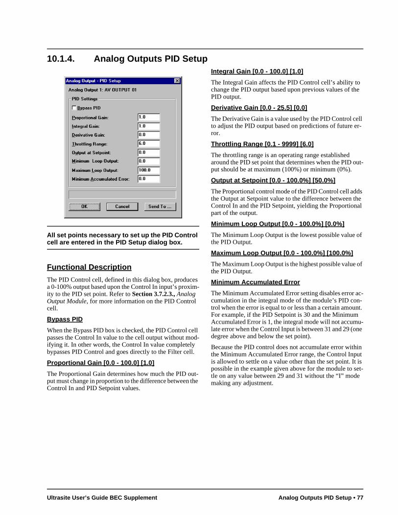
he
ell r-
ut-
s he l
f
of
c--nt. u-ne
in t is et-
e
10.1.4. Analog Outputs PID Setup
All set points necessary to set up the PID Control cell are entered in the PID Setup dialog box.
Functional Description
The PID Control cell, defined in this dialog box, produces a 0-100% output based upon the Control In input’s proxim-ity to the PID set point. Refer to Section 3.7.2.3., Analog Output Module, for more information on the PID Control cell.
Bypass PID
When the Bypass PID box is checked, the PID Control cell passes the Control In value to the cell output without mod-ifying it. In other words, the Control In value completely bypasses PID Control and goes directly to the Filter cell.
Proportional Gain [0.0 - 100.0] [1.0]
The Proportional Gain determines how much the PID out-put must change in proportion to the difference between the Control In and PID Setpoint values.
Integral Gain [0.0 - 100.0] [1.0]
The Integral Gain affects the PID Control cell’s ability tochange the PID output based upon previous values of tPID output.
Derivative Gain [0.0 - 25.5] [0.0]
The Derivative Gain is a value used by the PID Control cto adjust the PID output based on predictions of future eror.
Throttling Range [0.1 - 9999] [6.0]
The throttling range is an operating range established around the PID set point that determines when the PID oput should be at maximum (100%) or minimum (0%).
Output at Setpoint [0.0 - 100.0%] [50.0%]
The Proportional control mode of the PID Control cell addthe Output at Setpoint value to the difference between tControl In and the PID Setpoint, yielding the Proportionapart of the output.
Minimum Loop Output [0.0 - 100.0%] [0.0%]
The Minimum Loop Output is the lowest possible value othe PID Output.
Maximum Loop Output [0.0 - 100.0%] [100.0%]
The Maximum Loop Output is the highest possible value the PID Output.
Minimum Accumulated Error
The Minimum Accumulated Error setting disables error acumulation in the integral mode of the module’s PID control when the error is equal to or less than a certain amouFor example, if the PID Setpoint is 30 and the MinimumAccumulated Error is 1, the integral mode will not accumlate error when the Control Input is between 31 and 29 (odegree above and below the set point).
Because the PID control does not accumulate error withthe Minimum Accumulated Error range, the Control Inpuis allowed to settle on a value other than the set point. Itpossible in the example given above for the module to stle on any value between 29 and 31 without the “I” modmaking any adjustment.
Ultrasite User’s Guide BEC Supplement Analog Outputs PID Setup • 77
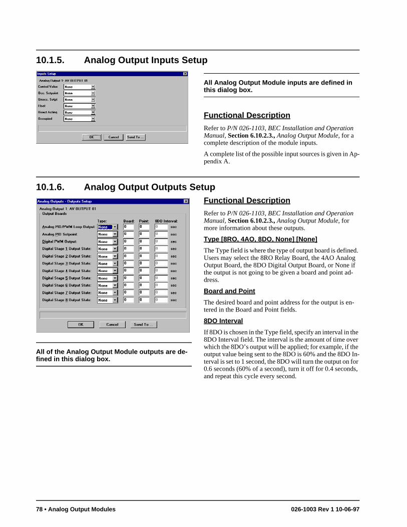
e In-or s,
10.1.5. Analog Output Inputs Setup
All Analog Output Module inputs are defined in this dialog box.
Functional Description
Refer to P/N 026-1103, BEC Installation and Operation Manual, Section 6.10.2.3., Analog Output Module, for a complete description of the module inputs.
A complete list of the possible input sources is given in Ap-pendix A.
10.1.6. Analog Output Outputs Setup
All of the Analog Output Module outputs are de-fined in this dialog box.
Functional Description
Refer to P/N 026-1103, BEC Installation and Operation Manual, Section 6.10.2.3., Analog Output Module, for more information about these outputs.
Type [8RO, 4AO, 8DO, None] [None]
The Type field is where the type of output board is defined. Users may select the 8RO Relay Board, the 4AO Analog Output Board, the 8DO Digital Output Board, or None if the output is not going to be given a board and point ad-dress.
Board and Point
The desired board and point address for the output is en-tered in the Board and Point fields.
8DO Interval
If 8DO is chosen in the Type field, specify an interval in the 8DO Interval field. The interval is the amount of time over which the 8DO’s output will be applied; for example, if thoutput value being sent to the 8DO is 60% and the 8DOterval is set to 1 second, the 8DO will turn the output on f0.6 seconds (60% of a second), turn it off for 0.4 secondand repeat this cycle every second.
78 • Analog Output Modules 026-1003 Rev 1 10-06-97
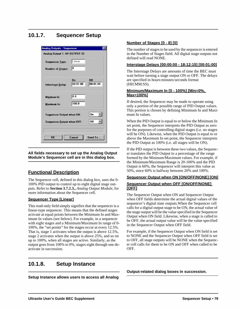
ered ot
st ys
g s. i-
n ro
es r ets
nc-e
if
t e ell
of cer to ed
et et
nc-be
10.1.7. Sequencer Setup
All fields necessary to set up the Analog Output Module’s Sequencer cell are in this dialog box.
Functional Description
The Sequencer cell, defined in this dialog box, uses the 0-100% PID output to control up to eight digital stage out-puts. Refer to Section 3.7.2.3., Analog Output Module, for more information about the Sequencer cell.
Sequencer Type [Linear]
This read-only field simply signifies that the sequencer is a linear-type sequencer. This means that the defined stages activate at equal points between the Minimum In and Max-imum In values (see below). For example, in a sequencer with eight stages and a Minimum/Maximum In range of 0-100%, the “set points” for the stages occur at every 12.5%. That is, stage 1 activates when the output is above 12.5%, stage 2 activates when the output is above 25%, and so on up to 100%, when all stages are active. Similarly, as the output goes from 100% to 0%, stages eight through one de-activate in succession.
Number of Stages [0 - 8] [0]
The number of stages to be used by the sequencer is entin the Number of Stages field. All digital stage outputs ndefined will read NONE.
Interstage Delays [00:00:00 - 18:12:15] [00:01:00]
The Interstage Delays are amounts of time the BEC muwait before turning a stage output ON or OFF. The delaare specified in hours:minutes:seconds format (HH:MM:SS).
Minimum/Maximum In [0 - 100%] [Min=0%, Max=100%]
If desired, the Sequencer may be made to operate usinonly a portion of the possible range of PID Output valueThis portion is chosen by defining Minimum In and Maxmum In values.
When the PID Output is equal to or below the Minimum Iset point, the Sequencer interprets the PID Output as zefor the purposes of controlling digital stages (i.e. no stagwill be ON). Likewise, when the PID Output is equal to oabove the Maximum In set point, the Sequencer interprthe PID Output as 100% (i.e. all stages will be ON).
If the PID output is between these two values, the Sequeer translates the PID Output to a percentage of the rangformed by the Mininum/Maximum values. For example, the Minimum/Maximum Range is 20-100% and the PIDOutput is 60%, the Sequencer will interpret this value as50%, since 60% is halfway between 20% and 100%.
Sequencer Output when ON [ON/OFF/NONE] [ON]
Sequencer Output when OFF [ON/OFF/NONE] [OFF]
The Sequencer Output when ON and Sequencer Outpuwhen OFF fields determine the actual digital values of thsequencer’s digital state outputs.When the Sequencer ccalls for a digital output stage to be ON, the actual valuethe stage output will be the value specified in the SequenOutput when ON field. Likewise, when a stage is called be OFF, the actual output value will be the value specifiin the Sequencer Output when OFF field.
For example, if the Sequencer Output when ON field is sto NONE and the Sequencer Output when OFF field is sto OFF, all stage outputs will be NONE when the Sequeer cell calls for them to be ON and OFF when called to OFF.
10.1.8. Setup Instance
Setup Instance allows users to access all Analog Output-related dialog boxes in succession.
Ultrasite User’s Guide BEC Supplement Sequencer Setup • 79

Functional Description
When Setup Instance is chosen, all dialog boxes related to analog input module setup appear in sequence. This allows users to change a number of settings without having to se-lect each dialog box individually from the system tree menu. When the module is created in UltraSite, the Setup Instance sequence is initiated automatically.
Setup Instance cycles through the dialog boxes in the fol-lowing order:
• Analog Output Module Setup - see Section 10.1.3.
• Analog Output Inputs - see Section 10.1.5.
• Analog Output Outputs - see Section 10.1.6.
• Analog Output PID Setup - see Section 10.1.4.
• Analog Output Sequencer - see Section 10.1.7.
• Analog Output Setpoints - see Section 10.1.2.
80 • Analog Output Modules 026-1003 Rev 1 10-06-97
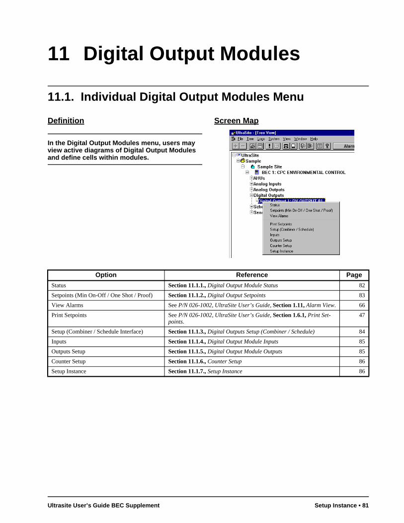
11 Digital Output Modules
11.1. Individual Digital Output Modules Menu
Definition
In the Digital Output Modules menu, users may view active diagrams of Digital Output Modules and define cells within modules.
Screen Map
Option Reference Page
Status Section 11.1.1., Digital Output Module Status 82
Setpoints (Min On-Off / One Shot / Proof) Section 11.1.2., Digital Output Setpoints 83
View Alarms See P/N 026-1002, UltraSite User’s Guide, Section 1.11, Alarm View. 66
Print Setpoints See P/N 026-1002, UltraSite User’s Guide, Section 1.6.1, Print Set-points.
47
Setup (Combiner / Schedule Interface) Section 11.1.3., Digital Outputs Setup (Combiner / Schedule) 84
Inputs Section 11.1.4., Digital Output Module Inputs 85
Outputs Setup Section 11.1.5., Digital Output Module Outputs 85
Counter Setup Section 11.1.6., Counter Setup 86
Setup Instance Section 11.1.7., Setup Instance 86
Ultrasite User’s Guide BEC Supplement Setup Instance • 81
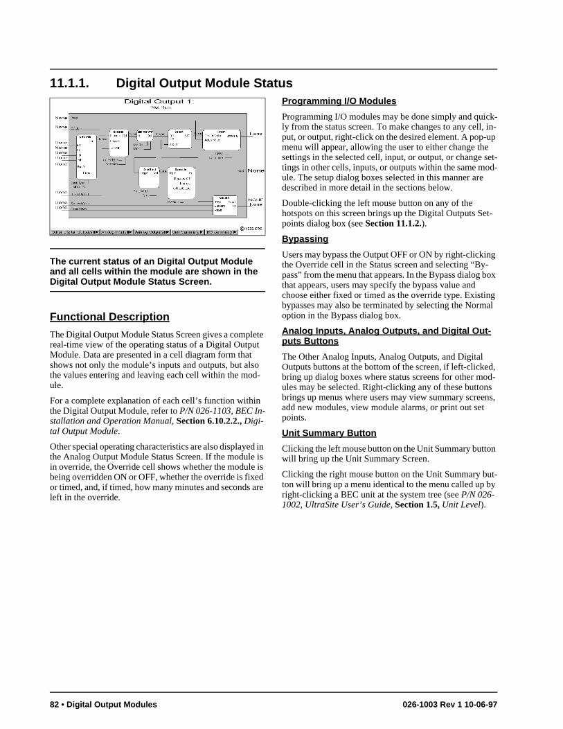
k- in-p
set-d-
t-
g -ox
g al
d, od-s ns,
t-y
11.1.1. Digital Output Module Status
The current status of an Digital Output Module and all cells within the module are shown in the Digital Output Module Status Screen.
Functional Description
The Digital Output Module Status Screen gives a complete real-time view of the operating status of a Digital Output Module. Data are presented in a cell diagram form that shows not only the module’s inputs and outputs, but also the values entering and leaving each cell within the mod-ule.
For a complete explanation of each cell’s function within the Digital Output Module, refer to P/N 026-1103, BEC In-stallation and Operation Manual, Section 6.10.2.2., Digi-tal Output Module.
Other special operating characteristics are also displayed in the Analog Output Module Status Screen. If the module is in override, the Override cell shows whether the module is being overridden ON or OFF, whether the override is fixed or timed, and, if timed, how many minutes and seconds are left in the override.
Programming I/O Modules
Programming I/O modules may be done simply and quicly from the status screen. To make changes to any cell,put, or output, right-click on the desired element. A pop-umenu will appear, allowing the user to either change thesettings in the selected cell, input, or output, or change tings in other cells, inputs, or outputs within the same moule. The setup dialog boxes selected in this manner aredescribed in more detail in the sections below.
Double-clicking the left mouse button on any of the hotspots on this screen brings up the Digital Outputs Sepoints dialog box (see Section 11.1.2.).
Bypassing
Users may bypass the Output OFF or ON by right-clickinthe Override cell in the Status screen and selecting “Bypass” from the menu that appears. In the Bypass dialog bthat appears, users may specify the bypass value and choose either fixed or timed as the override type. Existinbypasses may also be terminated by selecting the Normoption in the Bypass dialog box.
Analog Inputs, Analog Outputs, and Digital Out-puts Buttons
The Other Analog Inputs, Analog Outputs, and Digital Outputs buttons at the bottom of the screen, if left-clickebring up dialog boxes where status screens for other mules may be selected. Right-clicking any of these buttonbrings up menus where users may view summary screeadd new modules, view module alarms, or print out set points.
Unit Summary Button
Clicking the left mouse button on the Unit Summary button will bring up the Unit Summary Screen.
Clicking the right mouse button on the Unit Summary buton will bring up a menu identical to the menu called up bright-clicking a BEC unit at the system tree (see P/N 026-1002, UltraSite User’s Guide, Section 1.5, Unit Level).
82 • Digital Output Modules 026-1003 Rev 1 10-06-97
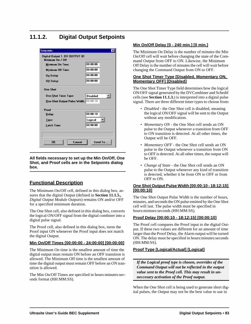
t
F
ll
n
rs, hot
t-e d ds
dig- in
11.1.2. Digital Output Setpoints
All fields necessary to set up the Min On/Off, One Shot, and Proof cells are in the Setpoints dialog box.
Functional Description
The Minimum On/Off cell, defined in this dialog box, as-sures that the digital Output (defined in Section 11.1.5., Digital Output Module Outputs) remains ON and/or OFF for a specified minimum duration.
The One Shot cell, also defined in this dialog box, converts the logical ON/OFF signal from the digital combiner into a digital pulse signal.
The Proof cell, also defined in this dialog box, turns the Proof input ON whenever the Proof input does not match the digital Output.
Min On/Off Times [00:00:00 - 24:00:00] [00:00:00]
The Minimum On time is the smallest amount of time the digital output must remain ON before an OFF transition is allowed. The Minimum Off time is the smallest amount of time the digital output must remain OFF before an ON tran-sition is allowed.
The Min On/Off Times are specified in hours:minutes:sec-onds format (HH:MM:SS).
Min On/Off Delay [0 - 240 min.] [0 min.]
The Minimum On Delay is the number of minutes the Min On/Off cell will wait before changing the state of the Com-mand Output from OFF to ON. Likewise, the Minimum Off Delay is the number of minutes the cell will wait before changing the Command Output from ON to OFF.
One Shot Timer Type [Disabled, Momentary ON, Momentary OFF] [Disabled]
The One Shot Timer Type field determines how the logical ON/OFF signal generated by the DVCombiner and Schedif cells (see Section 11.1.3.) is interpreted into a digital pulse signal. There are three different timer types to choose from:
• Disabled - the One Shot cell is disabled, meaning the logical ON/OFF signal will be sent to the Outpuwithout any modification.
• Momentary ON - the One Shot cell sends an ON pulse to the Output whenever a transition from OFto ON transition is detected. At all other times, theOutput will be OFF.
• Momentary OFF - the One Shot cell sends an ON pulse to the Output whenever a transition from ONto OFF is detected. At all other times, the output wibe OFF.
• Change of State - the One Shot cell sends an ON pulse to the Output whenever any kind of transitiois detected, whether it be from ON to OFF or fromOFF to ON.
One Shot Output Pulse Width [00:00:10 - 18:12:15] [00:00:10]
The One Shot Output Pulse Width is the number of houminutes, and seconds the ON pulse emitted by the One Scell will last. The pulse width must be specified in hours:mintues:seconds (HH:MM:SS).
Proof Delay [00:00:10 - 18:12:15] [00:00:10]
The Proof cell compares the Proof input to the digital Ouput. If these two values are different for an amount of timlarger than the Proof Delay, the Alarm output will be turneON. The delay must be specified in hours:minutes:secon(HH:MM:SS).
Proof Type [Logical/Actual] [Logical]
When the One Shot cell is being used to generate short ital pulses, the Output may not be the best value to use
If the Logical proof type is chosen, overrides of the Command Output will not be reflected in the output value sent to the Proof cell. This may result in un-neccesary activation of the Proof output.
Ultrasite User’s Guide BEC Supplement Digital Output Setpoints • 83
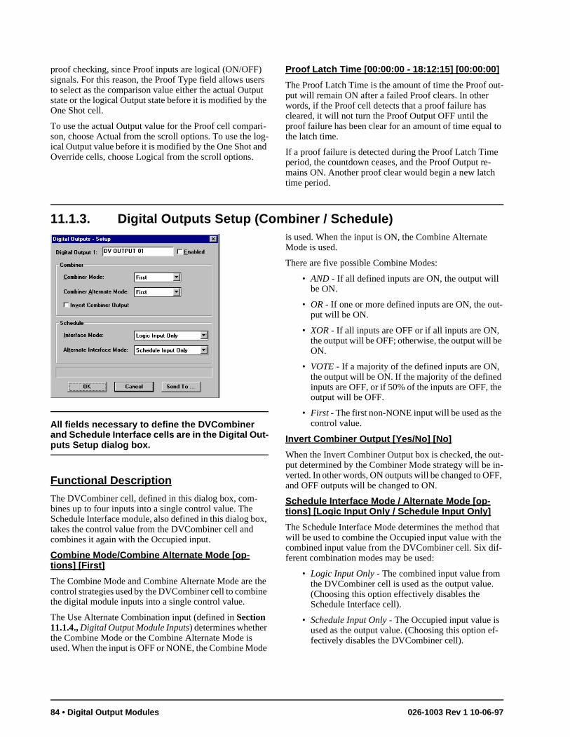
t-
e
ut-n-F,
at e -
f-
proof checking, since Proof inputs are logical (ON/OFF) signals. For this reason, the Proof Type field allows users to select as the comparison value either the actual Output state or the logical Output state before it is modified by the One Shot cell.
To use the actual Output value for the Proof cell compari-son, choose Actual from the scroll options. To use the log-ical Output value before it is modified by the One Shot and Override cells, choose Logical from the scroll options.
Proof Latch Time [00:00:00 - 18:12:15] [00:00:00]
The Proof Latch Time is the amount of time the Proof out-put will remain ON after a failed Proof clears. In other words, if the Proof cell detects that a proof failure has cleared, it will not turn the Proof Output OFF until the proof failure has been clear for an amount of time equal to the latch time.
If a proof failure is detected during the Proof Latch Time period, the countdown ceases, and the Proof Output re-mains ON. Another proof clear would begin a new latch time period.
11.1.3. Digital Outputs Setup (Combiner / Schedule)
All fields necessary to define the DVCombiner and Schedule Interface cells are in the Digital Out-puts Setup dialog box.
Functional Description
The DVCombiner cell, defined in this dialog box, com-bines up to four inputs into a single control value. The Schedule Interface module, also defined in this dialog box, takes the control value from the DVCombiner cell and combines it again with the Occupied input.
Combine Mode/Combine Alternate Mode [op-tions] [First]
The Combine Mode and Combine Alternate Mode are the control strategies used by the DVCombiner cell to combine the digital module inputs into a single control value.
The Use Alternate Combination input (defined in Section 11.1.4., Digital Output Module Inputs) determines whether the Combine Mode or the Combine Alternate Mode is used. When the input is OFF or NONE, the Combine Mode
is used. When the input is ON, the Combine Alternate Mode is used.
There are five possible Combine Modes:
• AND - If all defined inputs are ON, the output will be ON.
• OR - If one or more defined inputs are ON, the ouput will be ON.
• XOR - If all inputs are OFF or if all inputs are ON, the output will be OFF; otherwise, the output will beON.
• VOTE - If a majority of the defined inputs are ON, the output will be ON. If the majority of the definedinputs are OFF, or if 50% of the inputs are OFF, thoutput will be OFF.
• First - The first non-NONE input will be used as thecontrol value.
Invert Combiner Output [Yes/No] [No]
When the Invert Combiner Output box is checked, the oput determined by the Combiner Mode strategy will be iverted. In other words, ON outputs will be changed to OFand OFF outputs will be changed to ON.
Schedule Interface Mode / Alternate Mode [op-tions] [Logic Input Only / Schedule Input Only]
The Schedule Interface Mode determines the method thwill be used to combine the Occupied input value with thcombined input value from the DVCombiner cell. Six different combination modes may be used:
• Logic Input Only - The combined input value from the DVCombiner cell is used as the output value.(Choosing this option effectively disables the Schedule Interface cell).
• Schedule Input Only - The Occupied input value is used as the output value. (Choosing this option efectively disables the DVCombiner cell).
84 • Digital Output Modules 026-1003 Rev 1 10-06-97
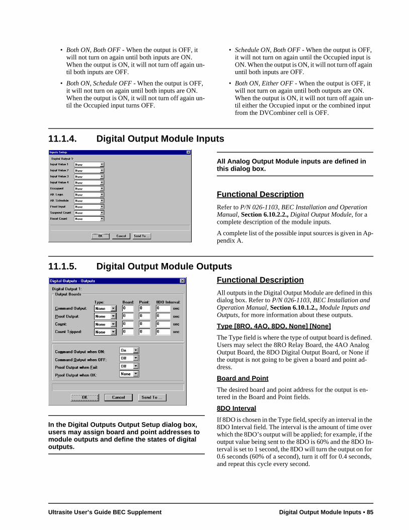
-t
p-
s
d. g -
n-
e r
e In-or s,
• Both ON, Both OFF - When the output is OFF, it will not turn on again until both inputs are ON. When the output is ON, it will not turn off again un-til both inputs are OFF.
• Both ON, Schedule OFF - When the output is OFF, it will not turn on again until both inputs are ON. When the output is ON, it will not turn off again un-til the Occupied input turns OFF.
• Schedule ON, Both OFF - When the output is OFF, it will not turn on again until the Occupied input isON. When the output is ON, it will not turn off againuntil both inputs are OFF.
• Both ON, Either OFF - When the output is OFF, it will not turn on again until both outputs are ON. When the output is ON, it will not turn off again until either the Occupied input or the combined inpufrom the DVCombiner cell is OFF.
11.1.4. Digital Output Module Inputs
All Analog Output Module inputs are defined in this dialog box.
Functional Description
Refer to P/N 026-1103, BEC Installation and Operation Manual, Section 6.10.2.2., Digital Output Module, for a complete description of the module inputs.
A complete list of the possible input sources is given in Apendix A.
11.1.5. Digital Output Module Outputs
In the Digital Outputs Output Setup dialog box, users may assign board and point addresses to module outputs and define the states of digital outputs.
Functional Description
All outputs in the Digital Output Module are defined in thidialog box. Refer to P/N 026-1103, BEC Installation and Operation Manual, Section 6.10.1.2., Module Inputs and Outputs, for more information about these outputs.
Type [8RO, 4AO, 8DO, None] [None]
The Type field is where the type of output board is defineUsers may select the 8RO Relay Board, the 4AO AnaloOutput Board, the 8DO Digital Output Board, or None ifthe output is not going to be given a board and point address.
Board and Point
The desired board and point address for the output is etered in the Board and Point fields.
8DO Interval
If 8DO is chosen in the Type field, specify an interval in th8DO Interval field. The interval is the amount of time ovewhich the 8DO’s output will be applied; for example, if thoutput value being sent to the 8DO is 60% and the 8DOterval is set to 1 second, the 8DO will turn the output on f0.6 seconds (60% of a second), turn it off for 0.4 secondand repeat this cycle every second.
Ultrasite User’s Guide BEC Supplement Digital Output Module Inputs • 85
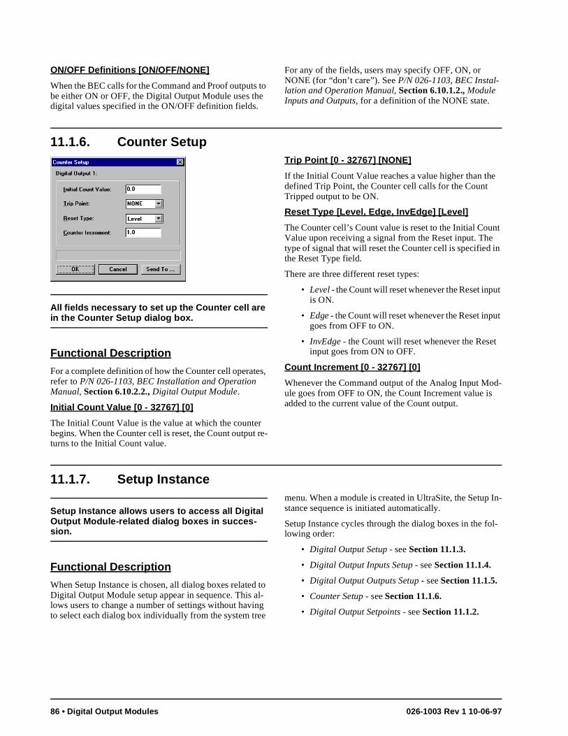
e
nt in
t
t
d-
In-
l-
ON/OFF Definitions [ON/OFF/NONE]
When the BEC calls for the Command and Proof outputs to be either ON or OFF, the Digital Output Module uses the digital values specified in the ON/OFF definition fields.
For any of the fields, users may specify OFF, ON, or NONE (for “don’t care”). See P/N 026-1103, BEC Instal-lation and Operation Manual, Section 6.10.1.2., Module Inputs and Outputs, for a definition of the NONE state.
11.1.6. Counter Setup
All fields necessary to set up the Counter cell are in the Counter Setup dialog box.
Functional Description
For a complete definition of how the Counter cell operates, refer to P/N 026-1103, BEC Installation and Operation Manual, Section 6.10.2.2., Digital Output Module.
Initial Count Value [0 - 32767] [0]
The Initial Count Value is the value at which the counter begins. When the Counter cell is reset, the Count output re-turns to the Initial Count value.
Trip Point [0 - 32767] [NONE]
If the Initial Count Value reaches a value higher than thdefined Trip Point, the Counter cell calls for the Count Tripped output to be ON.
Reset Type [Level, Edge, InvEdge] [Level]
The Counter cell’s Count value is reset to the Initial CouValue upon receiving a signal from the Reset input. Thetype of signal that will reset the Counter cell is specified the Reset Type field.
There are three different reset types:
• Level - the Count will reset whenever the Reset inpuis ON.
• Edge - the Count will reset whenever the Reset inpugoes from OFF to ON.
• InvEdge - the Count will reset whenever the Resetinput goes from ON to OFF.
Count Increment [0 - 32767] [0]
Whenever the Command output of the Analog Input Moule goes from OFF to ON, the Count Increment value isadded to the current value of the Count output.
11.1.7. Setup Instance
Setup Instance allows users to access all Digital Output Module-related dialog boxes in succes-sion.
Functional Description
When Setup Instance is chosen, all dialog boxes related to Digital Output Module setup appear in sequence. This al-lows users to change a number of settings without having to select each dialog box individually from the system tree
menu. When a module is created in UltraSite, the Setupstance sequence is initiated automatically.
Setup Instance cycles through the dialog boxes in the folowing order:
• Digital Output Setup - see Section 11.1.3.
• Digital Output Inputs Setup - see Section 11.1.4.
• Digital Output Outputs Setup - see Section 11.1.5.
• Counter Setup - see Section 11.1.6.
• Digital Output Setpoints - see Section 11.1.2.
86 • Digital Output Modules 026-1003 Rev 1 10-06-97
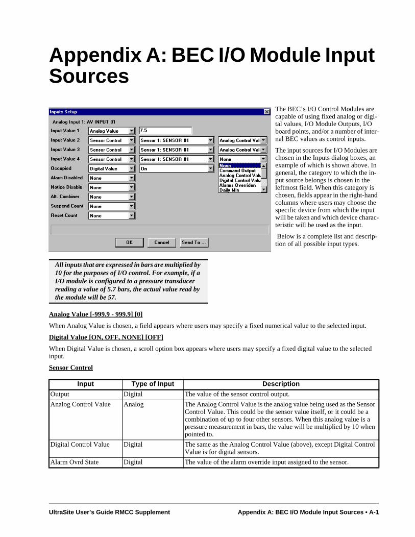
-
d e
-
put.
lected
nsor a en
trol
Appendix A: BEC I/O Module Input Sources
The BEC’s I/O Control Modules are capable of using fixed analog or digi-tal values, I/O Module Outputs, I/O board points, and/or a number of internal BEC values as control inputs.
The input sources for I/O Modules arechosen in the Inputs dialog boxes, anexample of which is shown above. Ingeneral, the category to which the in-put source belongs is chosen in the leftmost field. When this category is chosen, fields appear in the right-hancolumns where users may choose thspecific device from which the input will be taken and which device characteristic will be used as the input.
Below is a complete list and descrip-tion of all possible input types.
Analog Value [-999.9 - 999.9] [0]
When Analog Value is chosen, a field appears where users may specify a fixed numerical value to the selected in
Digital Value [ON, OFF, NONE] [OFF]
When Digital Value is chosen, a scroll option box appears where users may specify a fixed digital value to the seinput.
Sensor Control
All inputs that are expressed in bars are multiplied by 10 for the purposes of I/O control. For example, if a I/O module is configured to a pressure transducer reading a value of 5.7 bars, the actual value read by the module will be 57.
Input Type of Input Description
Output Digital The value of the sensor control output.
Analog Control Value Analog The Analog Control Value is the analog value being used as the SeControl Value. This could be the sensor value itself, or it could be acombination of up to four other sensors. When this analog value is pressure measurement in bars, the value will be multiplied by 10 whpointed to.
Digital Control Value Digital The same as the Analog Control Value (above), except Digital ConValue is for digital sensors.
Alarm Ovrd State Digital The value of the alarm override input assigned to the sensor.
UltraSite User’s Guide RMCC Supplement Appendix A: BEC I/O Module Input Sources • A-1
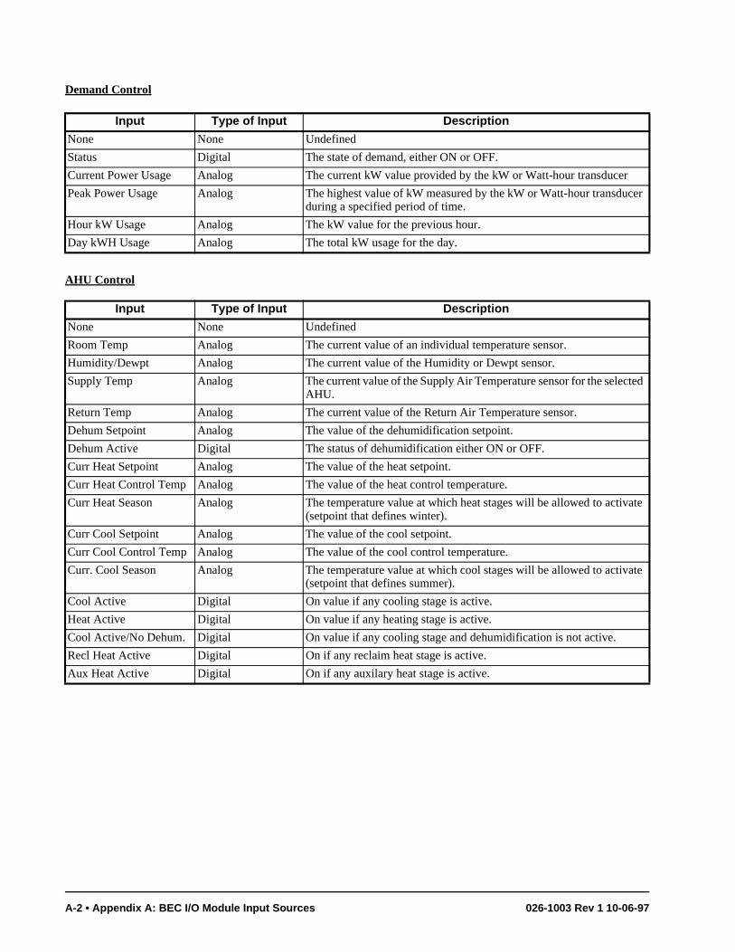
Demand Control
AHU Control
Input Type of Input Description
None None Undefined
Status Digital The state of demand, either ON or OFF.
Current Power Usage Analog The current kW value provided by the kW or Watt-hour transducer
Peak Power Usage Analog The highest value of kW measured by the kW or Watt-hour transducer during a specified period of time.
Hour kW Usage Analog The kW value for the previous hour.
Day kWH Usage Analog The total kW usage for the day.
Input Type of Input Description
None None Undefined
Room Temp Analog The current value of an individual temperature sensor.
Humidity/Dewpt Analog The current value of the Humidity or Dewpt sensor.
Supply Temp Analog The current value of the Supply Air Temperature sensor for the selected AHU.
Return Temp Analog The current value of the Return Air Temperature sensor.
Dehum Setpoint Analog The value of the dehumidification setpoint.
Dehum Active Digital The status of dehumidification either ON or OFF.
Curr Heat Setpoint Analog The value of the heat setpoint.
Curr Heat Control Temp Analog The value of the heat control temperature.
Curr Heat Season Analog The temperature value at which heat stages will be allowed to activate (setpoint that defines winter).
Curr Cool Setpoint Analog The value of the cool setpoint.
Curr Cool Control Temp Analog The value of the cool control temperature.
Curr. Cool Season Analog The temperature value at which cool stages will be allowed to activate (setpoint that defines summer).
Cool Active Digital On value if any cooling stage is active.
Heat Active Digital On value if any heating stage is active.
Cool Active/No Dehum. Digital On value if any cooling stage and dehumidification is not active.
Recl Heat Active Digital On if any reclaim heat stage is active.
Aux Heat Active Digital On if any auxilary heat stage is active.
A-2 • Appendix A: BEC I/O Module Input Sources 026-1003 Rev 1 10-06-97
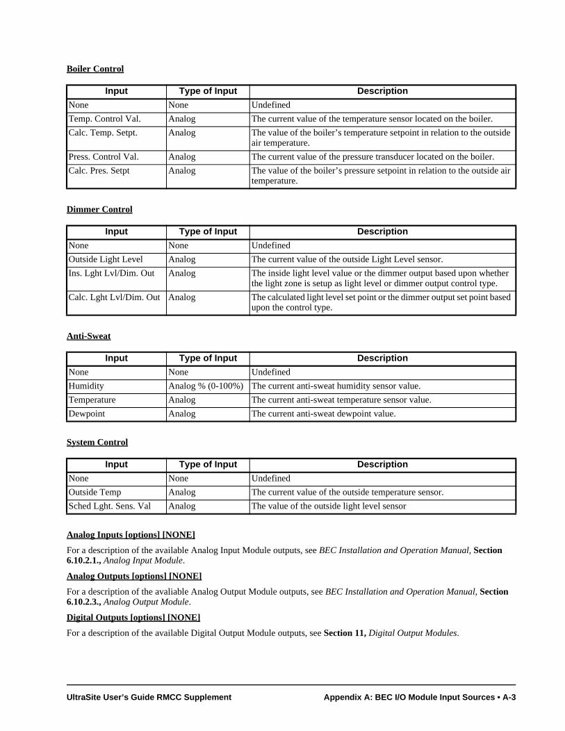
de
r.
e air
her
sed
Boiler Control
Dimmer Control
Anti-Sweat
System Control
Analog Inputs [options] [NONE]
For a description of the available Analog Input Module outputs, see BEC Installation and Operation Manual, Section 6.10.2.1., Analog Input Module.
Analog Outputs [options] [NONE]
For a description of the avaliable Analog Output Module outputs, see BEC Installation and Operation Manual, Section 6.10.2.3., Analog Output Module.
Digital Outputs [options] [NONE]
For a description of the available Digital Output Module outputs, see Section 11, Digital Output Modules.
Input Type of Input Description
None None Undefined
Temp. Control Val. Analog The current value of the temperature sensor located on the boiler.
Calc. Temp. Setpt. Analog The value of the boiler’s temperature setpoint in relation to the outsiair temperature.
Press. Control Val. Analog The current value of the pressure transducer located on the boile
Calc. Pres. Setpt Analog The value of the boiler’s pressure setpoint in relation to the outsidtemperature.
Input Type of Input Description
None None Undefined
Outside Light Level Analog The current value of the outside Light Level sensor.
Ins. Lght Lvl/Dim. Out Analog The inside light level value or the dimmer output based upon whetthe light zone is setup as light level or dimmer output control type.
Calc. Lght Lvl/Dim. Out Analog The calculated light level set point or the dimmer output set point baupon the control type.
Input Type of Input Description
None None Undefined
Humidity Analog % (0-100%) The current anti-sweat humidity sensor value.
Temperature Analog The current anti-sweat temperature sensor value.
Dewpoint Analog The current anti-sweat dewpoint value.
Input Type of Input Description
None None Undefined
Outside Temp Analog The current value of the outside temperature sensor.
Sched Lght. Sens. Val Analog The value of the outside light level sensor
UltraSite User’s Guide RMCC Supplement Appendix A: BEC I/O Module Input Sources • A-3
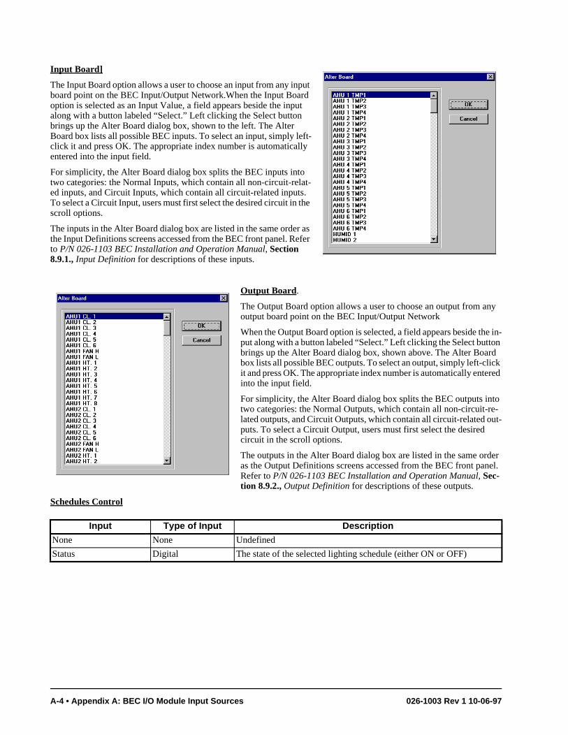
ny
e in-on d
ick red
to e-ut-
der nel.
Input Board]
The Input Board option allows a user to choose an input from any input board point on the BEC Input/Output Network.When the Input Board option is selected as an Input Value, a field appears beside the input along with a button labeled “Select.” Left clicking the Select button brings up the Alter Board dialog box, shown to the left. The Alter Board box lists all possible BEC inputs. To select an input, simply left-click it and press OK. The appropriate index number is automatically entered into the input field.
For simplicity, the Alter Board dialog box splits the BEC inputs into two categories: the Normal Inputs, which contain all non-circuit-relat-ed inputs, and Circuit Inputs, which contain all circuit-related inputs. To select a Circuit Input, users must first select the desired circuit in the scroll options.
The inputs in the Alter Board dialog box are listed in the same order as the Input Definitions screens accessed from the BEC front panel. Refer to P/N 026-1103 BEC Installation and Operation Manual, Section 8.9.1., Input Definition for descriptions of these inputs.
Output Board.
The Output Board option allows a user to choose an output from aoutput board point on the BEC Input/Output Network
When the Output Board option is selected, a field appears beside thput along with a button labeled “Select.” Left clicking the Select buttbrings up the Alter Board dialog box, shown above. The Alter Boarbox lists all possible BEC outputs. To select an output, simply left-clit and press OK. The appropriate index number is automatically enteinto the input field.
For simplicity, the Alter Board dialog box splits the BEC outputs intwo categories: the Normal Outputs, which contain all non-circuit-rlated outputs, and Circuit Outputs, which contain all circuit-related oputs. To select a Circuit Output, users must first select the desiredcircuit in the scroll options.
The outputs in the Alter Board dialog box are listed in the same oras the Output Definitions screens accessed from the BEC front paRefer to P/N 026-1103 BEC Installation and Operation Manual, Sec-tion 8.9.2., Output Definition for descriptions of these outputs.
Schedules Control
Input Type of Input Description
None None Undefined
Status Digital The state of the selected lighting schedule (either ON or OFF)
A-4 • Appendix A: BEC I/O Module Input Sources 026-1003 Rev 1 10-06-97

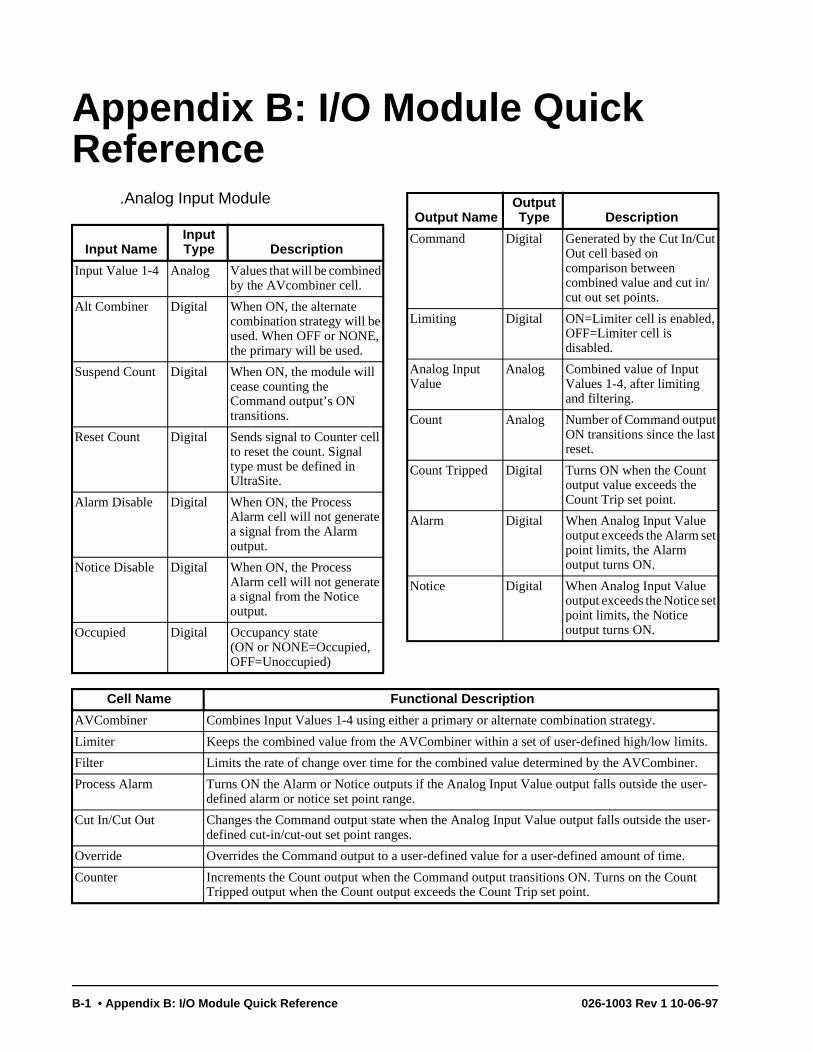
t
t
t
ts.
r.
ser-
user-
.
unt
Appendix B: I/O Module Quick Reference
.Analog Input Module
Input NameInput Type Description
Input Value 1-4 Analog Values that will be combined by the AVcombiner cell.
Alt Combiner Digital When ON, the alternate combination strategy will be used. When OFF or NONE, the primary will be used.
Suspend Count Digital When ON, the module will cease counting the Command output’s ON transitions.
Reset Count Digital Sends signal to Counter cell to reset the count. Signal type must be defined in UltraSite.
Alarm Disable Digital When ON, the Process Alarm cell will not generate a signal from the Alarm output.
Notice Disable Digital When ON, the Process Alarm cell will not generate a signal from the Notice output.
Occupied Digital Occupancy state (ON or NONE=Occupied, OFF=Unoccupied)
Output NameOutput Type Description
Command Digital Generated by the Cut In/CuOut cell based on comparison between combined value and cut in/cut out set points.
Limiting Digital ON=Limiter cell is enabled,OFF=Limiter cell is disabled.
Analog Input Value
Analog Combined value of Input Values 1-4, after limiting and filtering.
Count Analog Number of Command outpuON transitions since the lastreset.
Count Tripped Digital Turns ON when the Count output value exceeds the Count Trip set point.
Alarm Digital When Analog Input Value output exceeds the Alarm setpoint limits, the Alarm output turns ON.
Notice Digital When Analog Input Value output exceeds the Notice sepoint limits, the Notice output turns ON.
Cell Name Functional Description
AVCombiner Combines Input Values 1-4 using either a primary or alternate combination strategy.
Limiter Keeps the combined value from the AVCombiner within a set of user-defined high/low limi
Filter Limits the rate of change over time for the combined value determined by the AVCombine
Process Alarm Turns ON the Alarm or Notice outputs if the Analog Input Value output falls outside the udefined alarm or notice set point range.
Cut In/Cut Out Changes the Command output state when the Analog Input Value output falls outside thedefined cut-in/cut-out set point ranges.
Override Overrides the Command output to a user-defined value for a user-defined amount of time
Counter Increments the Count output when the Command output transitions ON. Turns on the CoTripped output when the Count output exceeds the Count Trip set point.
B-1 • Appendix B: I/O Module Quick Reference 026-1003 Rev 1 10-06-97
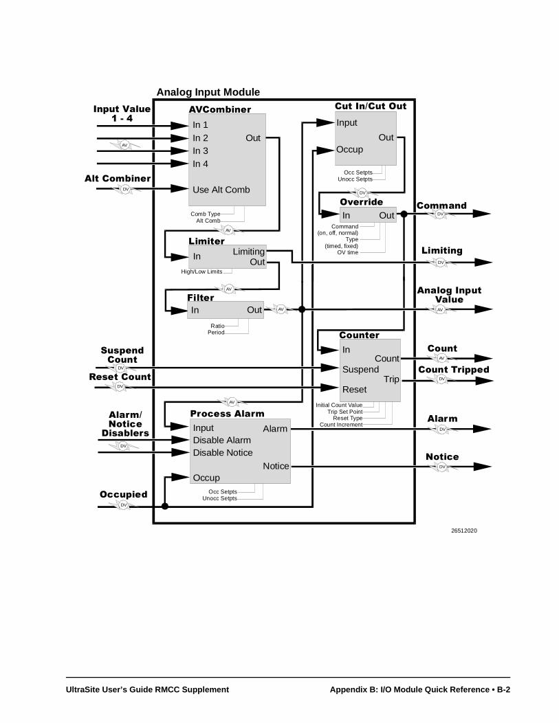
Analog Input Module
,QSXW�9DOXH�����
In 1In 2In 3In 4
Use Alt Comb
Out
RatioPeriod
$9&RPELQHU
)LOWHU
AV
3URFHVV�$ODUP
InputDisable AlarmDisable Notice
Occup
Alarm
Notice
DV
DV
DV
DV
DV
2FFXSLHG
$ODUP�1RWLFH
'LVDEOHUV
Occ SetptsUnocc Setpts
$QDORJ�,QSXW�9DOXH
&XW�,Q�&XW�2XW
Input
OccupOut
In Out
2YHUULGH
Occ SetptsUnocc Setpts
DV
Command(on, off, normal)
Type(timed, fixed)
OV time
&RPPDQG
$ODUP
&RXQWHU
In
Suspend
Reset
Count
Trip
Initial Count ValueTrip Set Point
Reset TypeCount Increment
Comb TypeAlt Comb
DV
AV
&RXQW
&RXQW�7ULSSHG
$OW�&RPELQHU
6XVSHQG&RXQW
5HVHW�&RXQW
1RWLFH
/LPLWHU
High/Low Limits
AV
AVAV
DV
DV
/LPLWLQJ
AV
OutIn
DV
DV
AV
In LimitingOut
26512020
UltraSite User’s Guide RMCC Supplement Appendix B: I/O Module Quick Reference • B-2
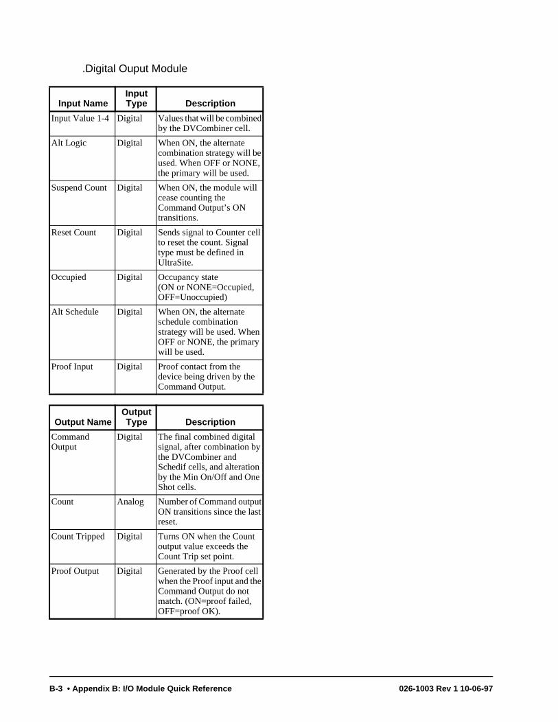
.Digital Ouput Module
Input NameInput Type Description
Input Value 1-4 Digital Values that will be combined by the DVCombiner cell.
Alt Logic Digital When ON, the alternate combination strategy will be used. When OFF or NONE, the primary will be used.
Suspend Count Digital When ON, the module will cease counting the Command Output’s ON transitions.
Reset Count Digital Sends signal to Counter cell to reset the count. Signal type must be defined in UltraSite.
Occupied Digital Occupancy state (ON or NONE=Occupied, OFF=Unoccupied)
Alt Schedule Digital When ON, the alternate schedule combination strategy will be used. When OFF or NONE, the primary will be used.
Proof Input Digital Proof contact from the device being driven by the Command Output.
Output NameOutput Type Description
Command Output
Digital The final combined digital signal, after combination by the DVCombiner and Schedif cells, and alteration by the Min On/Off and One Shot cells.
Count Analog Number of Command output ON transitions since the last reset.
Count Tripped Digital Turns ON when the Count output value exceeds the Count Trip set point.
Proof Output Digital Generated by the Proof cell when the Proof input and the Command Output do not match. (ON=proof failed, OFF=proof OK).
B-3 • Appendix B: I/O Module Quick Reference 026-1003 Rev 1 10-06-97
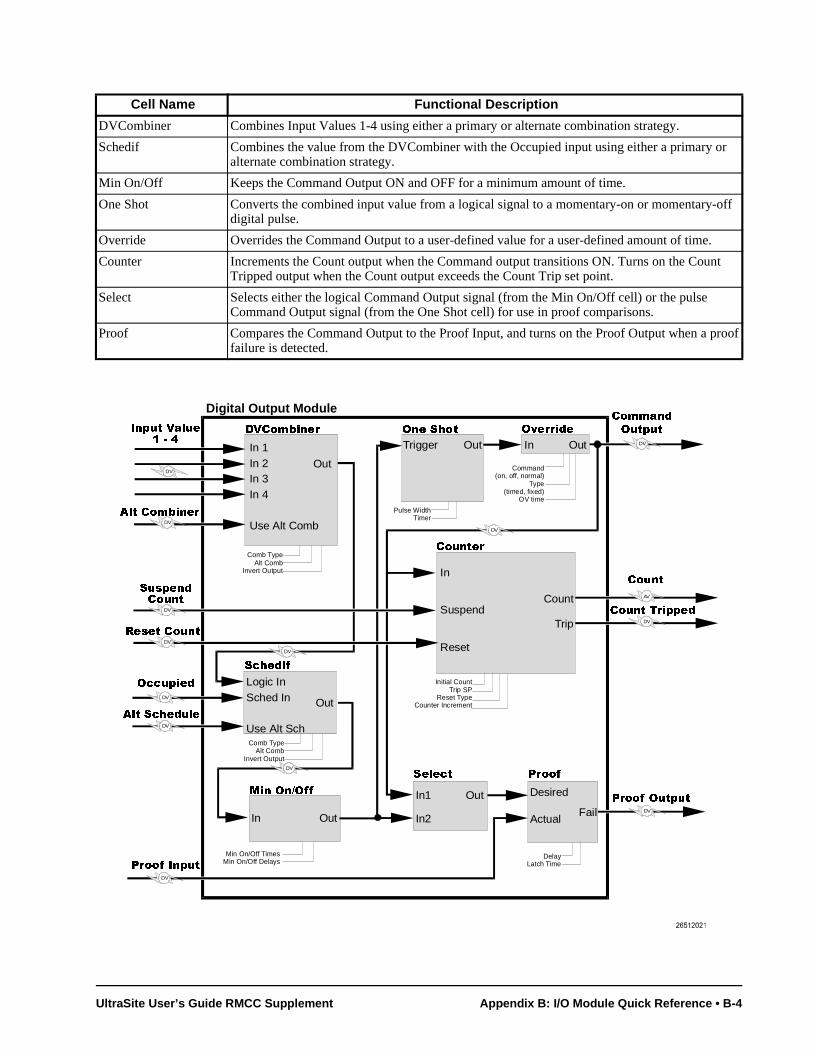
Cell Name Functional Description
DVCombiner Combines Input Values 1-4 using either a primary or alternate combination strategy.
Schedif Combines the value from the DVCombiner with the Occupied input using either a primary or alternate combination strategy.
Min On/Off Keeps the Command Output ON and OFF for a minimum amount of time.
One Shot Converts the combined input value from a logical signal to a momentary-on or momentary-off digital pulse.
Override Overrides the Command Output to a user-defined value for a user-defined amount of time.
Counter Increments the Count output when the Command output transitions ON. Turns on the Count Tripped output when the Count output exceeds the Count Trip set point.
Select Selects either the logical Command Output signal (from the Min On/Off cell) or the pulse Command Output signal (from the One Shot cell) for use in proof comparisons.
Proof Compares the Command Output to the Proof Input, and turns on the Proof Output when a proof failure is detected.
Digital Output Module
,QSXW�9DOXH�����
In 1In 2In 3In 4
Use Alt Comb
Out
'9&RPELQHU
6FKHGLI
Out
Comb TypeAlt Comb
Invert Output
$OW�&RPELQHU
DV
DV
Logic InSched In
Use Alt Sch
2FFXSLHG
DV
Comb TypeAlt Comb
Invert Output
0LQ�2Q�2II
In
DelayLatch Time
Out
2QH�6KRW
Trigger Out In Out2YHUULGH
Command(on, off, normal)
Type(timed, fixed)
OV time
Pulse WidthTimer
$OW�6FKHGXOH
6HOHFW 3URRI
Out
DV
&RPPDQG
2XWSXW
DV
In1
In2
DV
DV
3URRI�,QSXW
Desired
ActualFail
3URRI�2XWSXW
DV
DV
&RXQWHU
In
Suspend
Reset
Count
Trip
Initial CountTrip SP
Reset TypeCounter Increment
DV
AV
&RXQW�7ULSSHGDV
DV
6XVSHQG&RXQW
DV
&RXQW
5HVHW�&RXQW
Min On/Off TimesMin On/Off Delays
UltraSite User’s Guide RMCC Supplement Appendix B: I/O Module Quick Reference • B-4
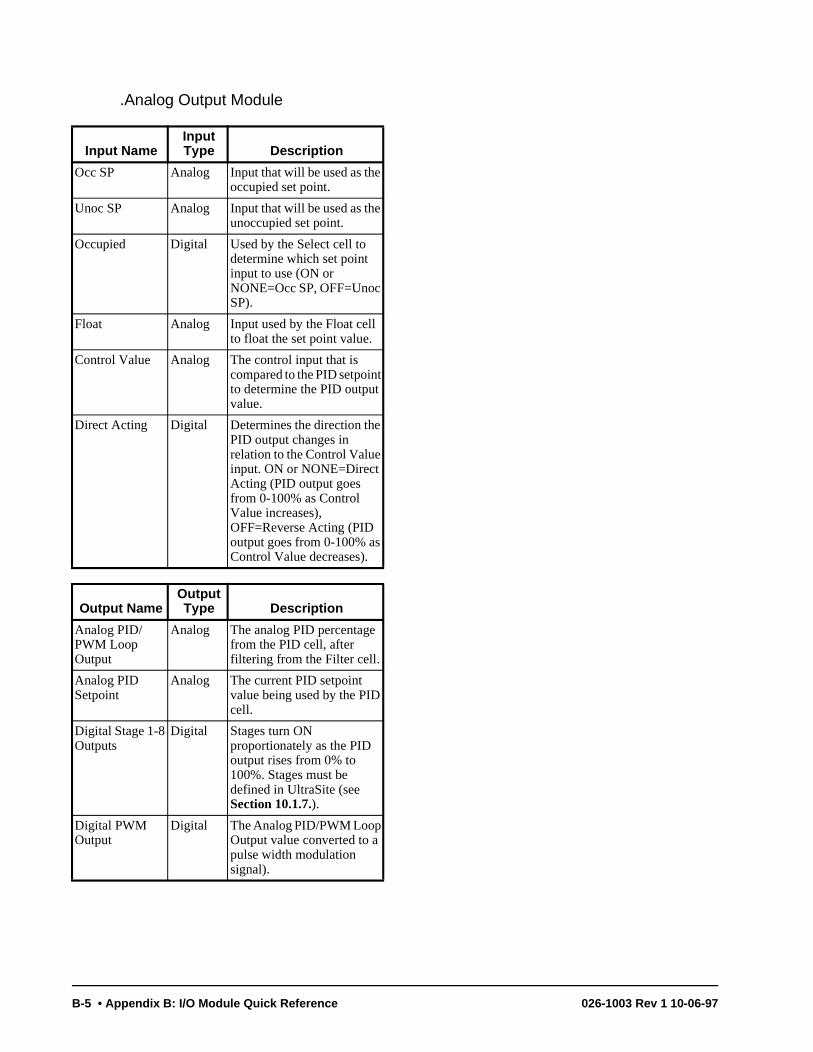
.Analog Output Module
Input NameInput Type Description
Occ SP Analog Input that will be used as the occupied set point.
Unoc SP Analog Input that will be used as the unoccupied set point.
Occupied Digital Used by the Select cell to determine which set point input to use (ON or NONE=Occ SP, OFF=Unoc SP).
Float Analog Input used by the Float cell to float the set point value.
Control Value Analog The control input that is compared to the PID setpoint to determine the PID output value.
Direct Acting Digital Determines the direction the PID output changes in relation to the Control Value input. ON or NONE=Direct Acting (PID output goes from 0-100% as Control Value increases), OFF=Reverse Acting (PID output goes from 0-100% as Control Value decreases).
Output NameOutput Type Description
Analog PID/PWM Loop Output
Analog The analog PID percentage from the PID cell, after filtering from the Filter cell.
Analog PID Setpoint
Analog The current PID setpoint value being used by the PID cell.
Digital Stage 1-8 Outputs
Digital Stages turn ON proportionately as the PID output rises from 0% to 100%. Stages must be defined in UltraSite (see Section 10.1.7.).
Digital PWM Output
Digital The Analog PID/PWM Loop Output value converted to a pulse width modulation signal).
B-5 • Appendix B: I/O Module Quick Reference 026-1003 Rev 1 10-06-97
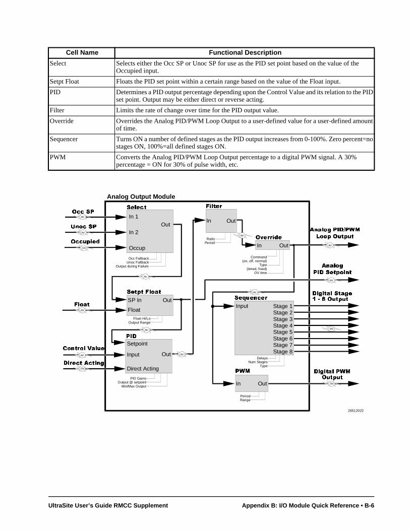
Cell Name Functional Description
Select Selects either the Occ SP or Unoc SP for use as the PID set point based on the value of the Occupied input.
Setpt Float Floats the PID set point within a certain range based on the value of the Float input.
PID Determines a PID output percentage depending upon the Control Value and its relation to the PID set point. Output may be either direct or reverse acting.
Filter Limits the rate of change over time for the PID output value.
Override Overrides the Analog PID/PWM Loop Output to a user-defined value for a user-defined amount of time.
Sequencer Turns ON a number of defined stages as the PID output increases from 0-100%. Zero percent=no stages ON, 100%=all defined stages ON.
PWM Converts the Analog PID/PWM Loop Output percentage to a digital PWM signal. A 30% percentage = ON for 30% of pulse width, etc.
Analog Output Module
In 1
In 2
Occup
Out
6HOHFW
6HWSW�)ORDW
OutSP In
&RQWURO�9DOXH
DV
PID GainsOutput @ setpoint
Min/Max Output
DV
RatioPeriod
AV
2FF�63
8QRF�63
2FFXSLHG
Float Hi/LoOutput Range
'LUHFW�$FWLQJ
AV
AV
AV
3,'
Setpoint
Input
Direct Acting
AV
$QDORJ
3,'�6HWSRLQW
)LOWHU
In Out
$QDORJ�3,'�3:0
/RRS�2XWSXW
In Out
2YHUULGH
Command(on, off, normal)
Type(timed, fixed)
OV time
AV
Stage 1Stage 2Stage 3Stage 4Stage 5Stage 6Stage 7Stage 8
Input
DelaysNum Stages
TypeDV
'LJLWDO�6WDJH������2XWSXW6HTXHQFHU
3:0
In Out
PeriodRange
DV
'LJLWDO�3:02XWSXW
Out
AV
AV
)ORDWFloat
AV
AV
AV
Occ FallbackUnoc Fallback
Output during Failure
26512022
UltraSite User’s Guide RMCC Supplement Appendix B: I/O Module Quick Reference • B-6

-
Index
Numerics4AO Analog Output Board
software setup 48DO Digital Output Board
software setup 48IO Board
software setup 48RO Form C Board
software setup 48RO Relay Board
software setup 4
AAdded Sensor Alarm Setpoint Shift 60AHU Fans
manual bypass 13setup 25
single-speed 25two-speed 25–26variable-speed 25, 26–27
AHUslog intervals 8manual bypassing
cooling 12fans 13heating 12
outside air dampers 15overrides 10run times
cooling 20fans 20heating 20
set pointsalarms
dehumidification 18
fans 18
heating/cooling 18cool termination 22cooling
separate strategy 17
single strategy 14cut-on and cut-off delays 16,
17dehumidification 14
interstage delay 15dehumidification reheat 15
time delay 15heating
separate strategy 16
single strategy 14minimum building tempera-
ture 15night set back
enabling 23
separate strategy 16, 17seasonal lock-out 23stage delays 15, 16terminate auxiliary heat 15warm-up 23winter/summer switch-over 8
setup 21–28control temperature strategy
22day start/end 8defining number of AHUs 8dewpoint sensor 22disabling heat during dehum
23enabling fans during fan fail 9external set point shift reset
time 8fail-safe 8fans 25–27humidity sensor 22number of stages 22seasonal set point shift 23set point strategy 8unoccupied mode 23
Air Dampers. See AHUs, Air Dampers.Alarm Dialout. See Communications.Alarms
analog sensor 60digital sensor 60power failure 3set points
AHUs 18Analog Input Module 65–71
alarmsclear delay 68high/low limits 68set points (occupied and unoc-
cupied) 67trip delay 68
cellsCombiner 68Counter 71
count increment 71
initial count 71
reset type 71
trip point 71Cut In/Cut Out 67Filter 68
enabling 69
factor 69Process Alarm 67
combination strategies 68enabling 68inputs
setup 70Use Alternate Combination 68
mix ratio 69naming 68outputs
Command 67Command, bypassing the 73ON/OFF definitions 70setup 70
set pointsalarms (occupied and unoccu
pied) 68count increment 71cut-in/cut-out 67cut-in/cut-out delays 67filter factor 69high/low limits 68initial counter value 71reset type 71trip point 71
setup instance 71Analog Output Module 72–79
cellsFilter 75
enabling 75
factor 75
time period 75PID Control 76
derivative gain 76
integral gain 76
min/max loop output 76
output at set point 76
proportional gain 76
throttling range 76Pulse Width Modulation
(PWM)output time 75
PWM 75min/max analog value 75
Select 74Sequencer 78
# of stages 78
min/max in 78Setpoint Float 74
float in low/high 74
float output range 74inputs
Float 74
UltraSite User’s Guide BEC Supplement Index • I-1
setup 77outputs
setup 77Sequencer
interstage delays 78set points
fallback 74filter factor 75filter time period 75float in low/high 74float output range 74min/max PWM analog value
75output when in failure 74PWM output time 75
setup instance 79Anti-Sweat
offsets 33overrides 30set points 33setup 30
BBEC
defining unit number 5Boilers 35–37
offsets 37set points 36setup 37
Building Environmental Control. See BEC.
CCommunications 5–6Cooling
bypassingmanual 12
coil air temperature 22set point strategy
separate 8single 8
unoccupied mode 23
DDaylight Savings Time 3Demand Control
alarm set points 42load shedding
set pointsAHUs 19
schedules 53
sensors 63setup
AHUs 27logs
daily 41
monthly 41window 41
set points 41–42demand 41demand window time 42load shed enable/disable times
42setup
kW sensors 41Dialout. See Communications.Digital Output Module 80–85
bypassing the output 81cells
Countercount increment 85
initial count value 85
trip point 85Counter reset type 85DVCombiner 83
combination modes 83
invert combiner output 83Minimum On/Off 82One Shot 82
output pulse width 82
timer type 82Proof
delay 82
latch time 83
type 82Schedule Interface 83
combination modes 83inputs
Proof 82Reset Count 85setup 84
outputsON/OFF definitions 85setup 84
set pointscount increment 85initial count value 85minimum ON/OFF times 82output pulse width 82proof delay 82proof latch time 83proof type 82reset type 85trip point 85
setup instance 85Digital Output Modules
cellsProof 82
Dimmer Control 44–47defining type 47
overrides 47set points 46–47setup 48
HHeating
bypassingmanual 12
set point strategyseparate 8single 8
unoccupied mode 23
IInput Definition
AHU humidity sensor 24AHU temp sensors 24air damper permit 24coil air termination sensors 24fan proof 24return air temperature sensor 24supply air temperature sensor 24variable-speed inverter alarm 24
Input DefinitionsAnalog Input Module 70Digital Output Module inputs 84
LLogs
intervalsAHU 8sensors 59
MModem. See Communications.
OOutput Definition
air dampers 24cool stages 24fans, high speed 24fans, low speed 24heating stages 24
Output DefinitionsDigital Output Module outputs 84
PPasswords 3–4
recording logons 3
RRun Times
clearing 20cooling 20fans 20heating 20
I-2 • Index 026-1003 Rev 1 10-06-97

SSchedules
defining events 51holidays 7overrides
digital 54light level sensor 51maintenance 52manual 53
special events 7Sensor Control
set pointscontrolled outputs 59
Sensorsalarms 60–61
analog 60digital 60
control strategy 59daily ON cycles 58event intervals 59logging interval 59offsets 59overrides
alarm 62output 62
run timesclearing 58daily ON time 58high/low values 58total 58total cycles 58
sensor types 64set points 59
unoccupied mode 61units 59unoccupied schedules 61
Setup InstanceAHUs 28anti-sweat 33boilers 37demand control circuits 43Digital Output Module 85dimmer lighting zones 48schedules 54sensors 64
Status ScreensAHUs 12–13Analog Input Module 66Analog Output Module 73Anti-Sweat 32Boiler 35–36Demand Control 40–41Digital Output Module 81Dimmer 45–46Sensor 57–58
UltraSite User’s Guide BEC Supplement Index • I-3