Embed Size (px)
Citation preview
micromanufacturing.com | 27
Accurately machining and measuring a part requires it to be located and clamped with
precision that matches or exceeds specifi ed fi nal tolerances. Generally, a shop can combine good machine tools, vises and tooling to get a good result. But when working with micron-level tolerances, good is not good enough. Beyond assembling high-accuracy workholding com-ponents, it is crucial to control how they relate to each other as an integrated system, and as-sure they are applied in a repeatable, system-atic manner.
Zero-point palletizing, or referencing sys-tems, can maximize precision in machining operations. In these systems, workholding pal-lets feature a centrally located drawbar or stud drawn into a machine-mounted chuck to pro-vide consistent positioning. “In the case of developing or validating a pro-
cess with small tools or small features, at some stage you have to remove the part and take it to a dedicated metrology device to inspect your re-sults,” said John Bradford, micromachining R&D
team leader for Makino Inc., Mason, Ohio. “You then put it back in the machine, make adjust-ments to your process and continue machin-ing. You must be able to remove, check and replace the part without repeating the whole setup process.”
Microcavity challengesPlastic Design Corp. (PDC), Scottsdale, Ariz., deals with those challenges every day. Th e com-pany manufactures molds and uses them to pro-duce small medical devices, microfl uidic circuits and in-vitro labware. “We are cutting true microcavities,” said PDC
President Mark Kinder. “Typically, we are doing one- and two-cavity tools; a luxury for us is a four-cavity mold. In the case of microfl uidic devices, he said, “the X-Y of the cavity may be pretty big—3" × 5"—but we are cutting features in the 30μm to 50μm range.” Machining features as small as 10μm, he said,
“is no big deal.” However, there are many vari-ables that aff ect the shop’s ability to consistently
All Systems GoShop takes ‘systems’ approach to holding microparts
By Bill Kennedy, Contributing Editor
Plastic Design
A micromold machined at Plastic Design is positioned on a Hermann Schmidt magnetic chuck mounted
on a unit of System 3R’s Nano reference system.
huck to pro-sistent positioning. “In the case of developing or validating a pro
cess with small tools or sm ll fstage you h
wo cavity tofour-cavity mold. In thdevices, he said “t
team leader for Mthen put it back iments to your proing. You must be replace the part wisetup process.”
Microcavity challePlastic Design Corpd
s Gmicropa
ed on a Hermann Sc
rp. (PDC), Scottsdale, Ariz., lenges every day. Th e com-olds and uses them to pro-vices, microfl uidic circuits
e microcavities,” said PDC r. “Typically, we are doingo ly are doing ools; a luxury for us is a he case of mi
check and ithout repeating the whole
engesrp (PDC)
Ultraprecision Machining
with MacroNano & MatrixNano
NANOless than 1 μm

3
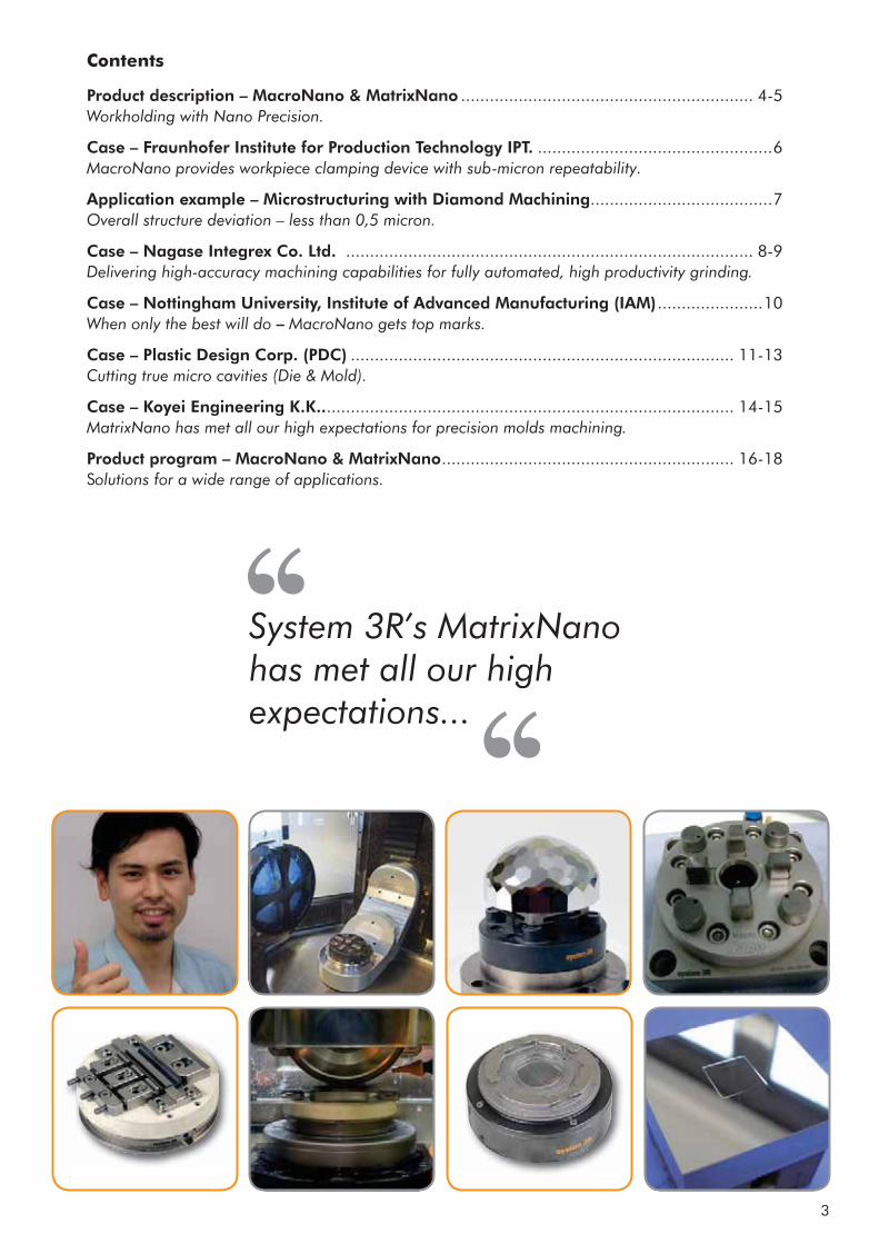
Product description – MacroNano & MatrixNano ............................................................. 4-5 Workholding with Nano Precision.
Case – Fraunhofer Institute for Production Technology IPT. .................................................6 MacroNano provides workpiece clamping device with sub-micron repeatability.
Application example – Microstructuring with Diamond Machining ......................................7 Overall structure deviation – less than 0,5 micron.
Case – Nagase Integrex Co. Ltd. ..................................................................................... 8-9 Delivering high-accuracy machining capabilities for fully automated, high productivity grinding.
Case – Nottingham University, Institute of Advanced Manufacturing (IAM) ......................10 When only the best will do – MacroNano gets top marks.
Case – Plastic Design Corp. (PDC) ................................................................................ 11-13 Cutting true micro cavities (Die & Mold).
Case – Koyei Engineering K.K.. ..................................................................................... 14-15 MatrixNano has met all our high expectations for precision molds machining.
Product program – MacroNano & MatrixNano ............................................................. 16-18 Solutions for a wide range of applications.
System 3R’s MatrixNano has met all our high expectations...
Contents
4
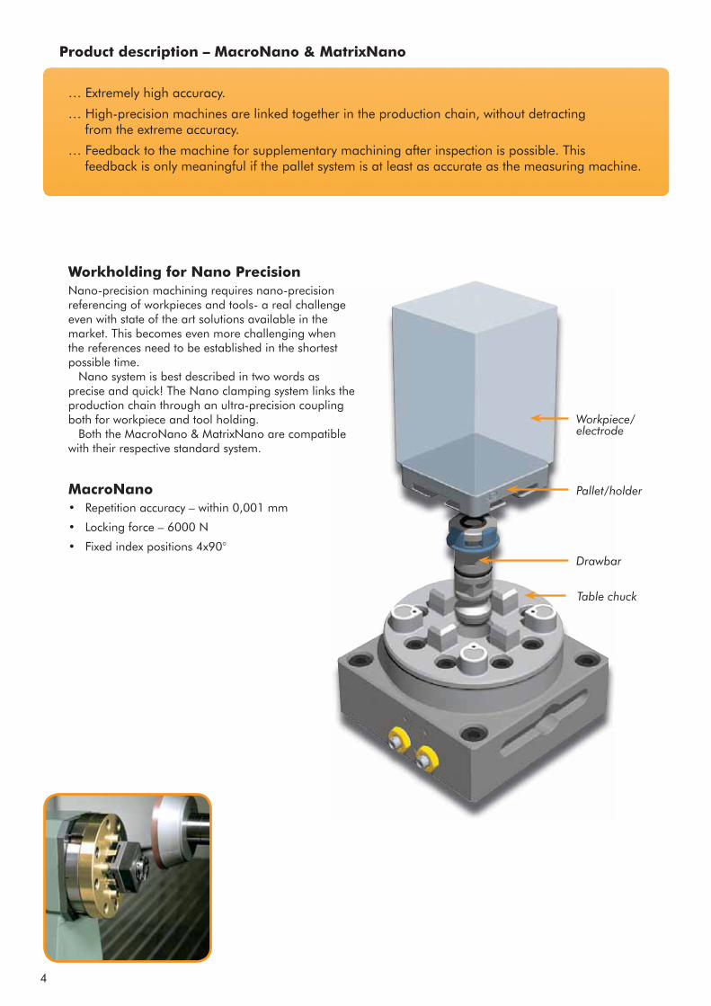
Drawbar
Pallet/holder
Workpiece/ electrode
Table chuck
Workholding for Nano PrecisionNano-precision machining requires nano-precision referencing of workpieces and tools- a real challenge even with state of the art solutions available in the market. This becomes even more challenging when the references need to be established in the shortest possible time.
Nano system is best described in two words as precise and quick! The Nano clamping system links the production chain through an ultra-precision coupling both for workpiece and tool holding.
Both the MacroNano & MatrixNano are compatible with their respective standard system.
MacroNano• Repetition accuracy – within 0,001 mm
• Locking force – 6000 N
• Fixed index positions 4x90°
Product description – MacroNano & MatrixNano
… Extremely high accuracy.
… High-precision machines are linked together in the production chain, without detracting from the extreme accuracy.
… Feedback to the machine for supplementary machining after inspection is possible. This feedback is only meaningful if the pallet system is at least as accurate as the measuring machine.
5
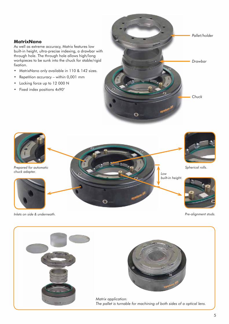
Chuck
Drawbar
Pallet/holder
MatrixNano As well as extreme accuracy, Matrix features low built-in height, ultra-precise indexing, a drawbar with through hole. The through hole allows high/long workpieces to be sunk into the chuck for stable/rigid fixation.• MatrixNano only available in 110 & 142 sizes.
• Repetition accuracy – within 0,001 mm
• Locking force up to 12 000 N
• Fixed index positions 4x90°
Low built-in height.
Spherical rolls.
Pre-alignment studs.Inlets on side & underneath.
Prepared for automatic chuck adapter.
Matrix application: The pallet is turnable for machining of both sides of a optical lens.
6
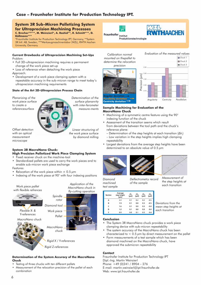
System 3R Sub-Micron Palletizing System for Ultraprecision Machining ProcessesC. Brecher*&***, M. Weinzierl*, A. Rashid**, R. Schmitt***, D. Köllmann****Fraunhofer Institute for Production Technology IPT, Germany, **System 3R Intl. AB, Sweden, ***Werkzeugmaschinenlabor (WZL), RWTH Aachen University, Germany
Current Drawbacks of Ultraprecision Machining Set-UpsProblem:• Full 3D-ultraprecision machining requires a permanent change of the work piece set-up• Loss of reference when detaching the work pieceApproach:• Development of a work piece clamping system with a repeatable accuracy in the sub-micron range to meet today’s ultraprecision machining requirements
System 3R MacroNano Chuck: High Precision Palletized Work Piece Clamping System • Fixed receiver chuck on the machine-tool• Standardized pallets are used to carry the work pieces and to enable sub-micron work piece exchangeFeatures:• Relocation of the work piece within ± 0.5 μm• Indexing of the work piece at 90° with four indexing positions
Determination of the System Accuracy of the MacroNano Chuck• Testing of three chucks with ten different pallets• Measurement of the relocation precision of the pallet of each combination
Sample Machining for Evaluation of the MacroNano Chuck• Machining of a symmetric centre feature using the 90° indexing function of the chuck• Assessment of the transition seems which result from deviations between the tool path and the chuck’s reference plane: – Determination of the step heights at each transition ( hi) – Low variation in the step heights implies high clamping repeatability• Largest deviations from the average step heights have been determined to an absolute value of 0.5 μm
Conclusion• The System 3R MacroNano chuck provides a work piece clamping device with sub-micron repeatability• The system accuracy of the MacroNano chuck has been characterized to < 0.5 μm by direct measurement on the pallet• Form measurements of a test sample which has been diamond machined on the MacroNano chuck, have approved the submicron repeatability
Planarizing of the work piece surface to create a referencesurface
Determination of the surface plananrity
with inter-ferometer measure-ments
Offset detection with an optical measurement microscope
Linear structuring of the work piece surface
by diamond milling
State of the Art 3D-Ultraprecision Process Chain
Flexible X- & Y-references
Work piece pallet with flexible refrences
MacroNano chuck
Application of the MacroNano chuck in fly-cutting operation
Spindle rotor
Diamond tool
Work piece
Pallet
MacroNano chuck
Rigid X / Y-references
Rigid Z-references
Angular deviationParallelity deviationCentricity deviation
Chuck 1
Chuck 2
Chuck 3
Angularity Centricity Parallelism
Prec
isio
n [μ
m]
0.50
0.40
0.30
0.20
0.10
Evaluation of the measured valuesCalibration normal mounted on thepallet to determine the relocation
precision
Reference plane
Centre artefact
Transitionseems
Diamond machined test sample
Measurement of the step heights at each transition
10 mm
Deviations from the mean step heights at each transition
Deflectrometry record of the sample
ContactFraunhofer Institute for Production Technology IPTDipl.-Ing. Martin WeinzierlPhone: +49 (0)241 / 8904 – 276E-mail: [email protected]: www.ipt.fraunhofer.de
Case – Fraunhofer Institute for Production Technology IPT.
7
w
l
w
l
dh
dv
dh
dv
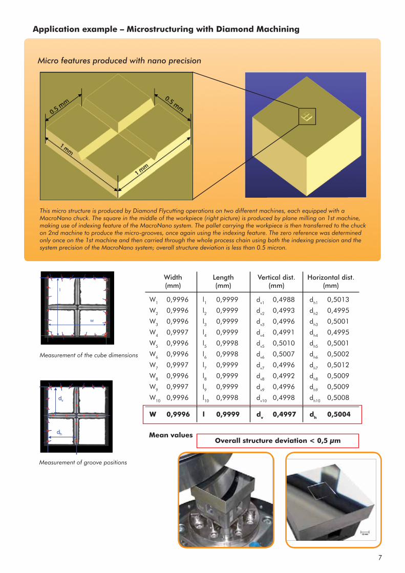
W1 0,9996 l1 0,9999 dv1 0,4988 dh1 0,5013
W2 0,9996 l2 0,9999 dv2 0,4993 dh2 0,4995
W3 0,9996 l3 0,9999 dv3 0,4996 dh3 0,5001
W4 0,9997 l4 0,9999 dv4 0,4991 dh4 0,4995
W5 0,9996 l5 0,9998 dv5 0,5010 dh5 0,5001
W6 0,9996 l6 0,9998 dv6 0,5007 dh6 0,5002
W7 0,9997 l7 0,9999 dv7 0,4996 dh7 0,5012
W8 0,9996 l8 0,9999 dv8 0,4992 dh8 0,5009
W9 0,9997 l9 0,9999 dv9 0,4996 dh9 0,5009
W10 0,9996 l10 0,9998 dv10 0,4998 dh10 0,5008
W 0,9996 l 0,9999 dv 0,4997 dh 0,5004
Application example – Microstructuring with Diamond Machining
This micro structure is produced by Diamond Flycutting operations on two different machines, each equipped with a MacroNano chuck. The square in the middle of the workpiece (right picture) is produced by plane milling on 1st machine, making use of indexing feature of the MacroNano system. The pallet carrying the workpiece is then transferred to the chuck on 2nd machine to produce the micro-grooves, once again using the indexing feature. The zero reference was determined only once on the 1st machine and then carried through the whole process chain using both the indexing precision and the system precision of the MacroNano system; overall structure deviation is less than 0.5 micron.
Micro features produced with nano precision
Measurement of the cube dimensions
Measurement of groove positions
Mean valuesOverall structure deviation < 0,5 μm
Width(mm)
Length(mm)
Vertical dist.(mm)
Horizontal dist.(mm)
8
Published in Incredible Concept (Japan)
Written by Kiyondo Adachi.
Grinding time halved by high-speed oscillation
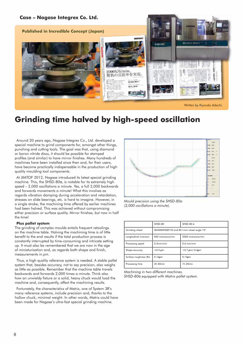
Around 20 years ago, Nagase Integrex Co., Ltd. developed a special machine to grind components for, amongst other things, punching and cutting tools. The goal was that, using diamond or boron nitride discs, it should be possible for stamped profiles (and similar) to have mirror finishes. Many hundreds of machines have been installed since then and, for their users, have become practically indispensable in the production of high quality moulding tool components.
At JIMTOF 2012, Nagase introduced its latest special grinding machine. This, the SHSD-80 , is notable for its extremely high speed – 2,000 oscillations a minute. Yes, a full 2,000 backwards and forwards movements a minute! What this involves as regards vibration damping during acceleration and retardation, stresses on slide bearings, etc. is hard to imagine. However, in a single stroke, the machining time offered by earlier machines had been halved. This was achieved without compromising either precision or surface quality. Mirror finishes, but now in half the time!
Plus pallet system The grinding of complex moulds entails frequent retoolings on the machine table. Halving the machining time is of little benefit to the end results if the total production process is constantly interrupted by time-consuming and intricate setting up. It must also be remembered that we are now in the age of miniaturisation and, as regards both shape and finish, measurements in μm.
Thus, a high quality reference system is needed. A stable pallet system that, besides accuracy, not to say precision, also weighs as little as possible. Remember that the machine table travels backwards and forwards 2,000 times a minute. Think also how an unwieldy fixture or a solid, heavy chuck would load the machine and, consequently, affect the machining results.
Fortunately, the characteristics of Matrix, one of System 3R’s many reference systems, include precision and, thanks to the hollow chuck, minimal weight. In other words, Matrix could have been made for Nagase’s ultra-fast special grinding machine.
Machining in two different machines. SHSD-80 equipped with Matrix pallet system.
Mould precision using the SHSD-80a (2,000 oscillations a minute).
Case – Nagase Integrex Co. Ltd.
SHSD-80 SHSD-80
Grinding wheel SD400MVDØ125 end R0.1mm wheel angle 15°
Longitudinal inversion 840 inversions/min 2000 inversions/min
Processing speed 0.3mm/min 0.6 mm/min
Shape accuracy ±0.5 μm +0.7 μm/-0.6μm
Surface roughness (Rz) 0.16μm 0.15μm
Processing time 2h 40min 1h 20min

9
Operation #1, grinding
Production cell that the Japanese Chamber of Commerce and Industry awarded the “President’s prize”. On the left side “behind the cover” Automation solution from System 3R – WorkPal Compact Servo.
...the pallet with workpiece turned 180° ...operation #2, grinding
Application example at Nagase – Makes it possible to complete the grinding operation in one Machine set-up.
Plus automation Although we are talking about halved machining time, the overall manufacturing frame is still hours and not seconds. After all, production here involves grinding, complex moulds and extreme finishes. There is more to it than simply feeding in the workpieces. Advantage has to be taken of every second in the day. This leads unavoidably to automated pallet changing!
System 3R’s wide programme of handling equipment includes the WorkPal Compact pallet changer. This unit changes workpieces (on their pallets) between a magazine and a pneumatic chuck on the machine table. A WorkPal Compact requires minimal floor space, is simple to install and easy to aesthetically adapt to the machine in question (which Nagase did).
On top of this, WorkPal Compact can be complemented with a suitable intermediate station. In this case, a rotating station that turns the pallet (with its workpiece) 180° between two grinding operations. This was necessary to fully exploit available grinding technology.
Thus, what Nagase presented at JIMTOF was not just an ultra-fast special grinding machine but, in fact, a fully automatic production cell with a production capacity that had never previously been approached. No wonder that it excited attention in the high quality moulding tools manufacturing industry!
Completed workpiece mounted on Matrix pallet.
Turned 180°

10
System 3R’s MacroNano workholding system gets top marks from Nottingham University’s Institute of Advanced ManufacturingPublished in CMM international
When only the best will do, Nottingham University turned to System 3R tooling for use on their metalcutting machines in their newly-opened Institute of Advanced Manufacturing (IAM).
This £3.5 million facility was opened by David Willetts, Minister of State for Universities and Science, in September 2012 who said, “ It is vital that business benefits from the very best and latest technologies in order to compete in the
global marketplace and be a driving force for growth.”
It focuses on driving the development of cutting-edge technology with the aim of radically improving all aspects of advanced manufacturing and has links with industry and has partners in such diverse sectors as aerospace, automotive, medical, instrumentation, defence, power engineering, sustainable energy, textiles and clothing, recycling and consumer products.
The increased demand for micro and nano precision manufacturing processes – especially within most of these industry sectors – led the IAM to fit MacroNano tooling on their latest EDM machine, a Sodick AQ750 wire erosion machine. 3R tooling is also fitted on their Sodick AP1L die-sinker spark , complete with an 8-position toolchanger and an AP200L wire machine.
MacroNano delivers repeatable sub-micron accuracy levels – as measured in tests by the world-renowned Fraunhofer
Institute for Production Technology IPT in Aachen, Germany. In ultraprecision machining of workpieces, initial measurements showed repeatability and system accuracy ‘well below 1 micron’. The best observed values were as low as 0.1micron! Workpieces and cutting tools and/or electrodes are mounted with the same precision and accuracy.
The assured repeatable accuracy gained from the mounting of workpieces for electrode manufacture on Macro pallets also guarantees that once the initial datum is entered, a part can be transferred from one machining process to another, without compromising its tolerance and positional integrity. The ability to run cost-effective lights out production has therefore now become a reality – especially where long cycle times on complex electrode manufacture is unavoidable.
The IAM’s Kern Evo machining centre has a pneumatic MacroNano chuck which, together with the pallets, incorporates System 3R’s innovative VDP (vibration damped palletisation) technology that provides a very rigid coupling on the machine table – not affected by the machine’s frequency and vibration. The mechanical interface between machine table, workpiece, machine spindle and tool is constant whether milling, grinding, turning or in an EDM machine.
Lab Manager, Daniel Smale, says, “Ideally we would like to put System 3R tooling on all our machines, but budgets are always under pressure.
“It helps minimise the errors between machines and saves time in switching a workpiece from each process, as complicated fixturing has become a thing of the past. Planning jobs is easier and if we need to get a part on a machine fast, the flexibility we have can be vital.”
Apart from the machines in the IAM, the PhD students at Nottingham
University also benefit from System 3R technology, as they have access to a Sodick AQ750L machine that is fitted with a range of tooling for their projects. So System 3R is helping to advance the boundaries of cutting-edge manufacturing for the engineers of today and tomorrow!
MacroNano workholding system in the wire erosion machine
System 3R’s MacroNano pneumatic chuck
Electrodes are fitted to Macro holders in the die-sinker’s toolchanger, which provide assured repeatable accuracy in the EDM process.
Case – Nottingham University, Institute of Advanced Manufacturing (IAM)
System 3R’s MacroNano workholding system gets top marks from Nottingham University’s Institute of Advanced ManufacturingPublished in CMM international
When only the best will do, Nottingham University turned to System 3R tooling for use on their metalcutting machines in their newly-opened Institute of Advanced Manufacturing (IAM).
This £3.5 million facility was opened by David Willetts, Minister of State for Universities and Science, in September 2012 who said, “ It is vital that business benefits from the very best and latest technologies in order to compete in the
global marketplace and be a driving force for growth.”
It focuses on driving the development of cutting-edge technology with the aim of radically improving all aspects of advanced manufacturing and has links with industry and has partners in such diverse sectors as aerospace, automotive, medical, instrumentation, defence, power engineering, sustainable energy, textiles and clothing, recycling and consumer products.
The increased demand for micro and nano precision manufacturing processes – especially within most of these industry sectors – led the IAM to fit MacroNano tooling on their latest EDM machine, a Sodick AQ750 wire erosion machine. 3R tooling is also fitted on their Sodick AP1L die-sinker spark , complete with an 8-position toolchanger and an AP200L wire machine.
MacroNano delivers repeatable sub-micron accuracy levels – as measured in tests by the world-renowned Fraunhofer
Institute for Production Technology IPT in Aachen, Germany. In ultraprecision machining of workpieces, initial measurements showed repeatability and system accuracy ‘well below 1 micron’. The best observed values were as low as 0.1micron! Workpieces and cutting tools and/or electrodes are mounted with the same precision and accuracy.
The assured repeatable accuracy gained from the mounting of workpieces for electrode manufacture on Macro pallets also guarantees that once the initial datum is entered, a part can be transferred from one machining process to another, without compromising its tolerance and positional integrity. The ability to run cost-effective lights out production has therefore now become a reality – especially where long cycle times on complex electrode manufacture is unavoidable.
The IAM’s Kern Evo machining centre has a pneumatic MacroNano chuck which, together with the pallets, incorporates System 3R’s innovative VDP (vibration damped palletisation) technology that provides a very rigid coupling on the machine table – not affected by the machine’s frequency and vibration. The mechanical interface between machine table, workpiece, machine spindle and tool is constant whether milling, grinding, turning or in an EDM machine.
Lab Manager, Daniel Smale, says, “Ideally we would like to put System 3R tooling on all our machines, but budgets are always under pressure.
“It helps minimise the errors between machines and saves time in switching a workpiece from each process, as complicated fixturing has become a thing of the past. Planning jobs is easier and if we need to get a part on a machine fast, the flexibility we have can be vital.”
Apart from the machines in the IAM, the PhD students at Nottingham
University also benefit from System 3R technology, as they have access to a Sodick AQ750L machine that is fitted with a range of tooling for their projects. So System 3R is helping to advance the boundaries of cutting-edge manufacturing for the engineers of today and tomorrow!
System 3R’s MacroNano pneumatic chuck
Electrodes are fitted to Macro holders in the die-sinker’s toolchanger, which provide assured repeatable accuracy in the EDM process.
Case – Nottingham University, Institute of Advanced Manufacturing (IAM)

11
tightly controlled. “If we want the reaction
of this chuck to be identical every
time, the procedure for opening and
closing the chuck must be as accurate as
everything else,” Sebzda said. While Sys-
tem 3R recommends air pressure in the
range of 5 to 7 bar (about 70 to 100 psi)
to operate its standard chucks, it recom-
mends air pressure for the Nano should
always be 6 bar.
One manufacturing challenge is that
advances in machine tool accuracy may
limit the usefulness of some palletizing
systems, according to Makino’s Brad-
ford. He cited machines such as Makino’s
Hyper 2J VMC that features 0.000000020"
(0.5nm) scale feedback with guaran-
teed positioning accuracy of ±0.3μm
(±0.000012") and repeatability accuracy
of ±0.2μm (±0.000008").
In actual applications, he noted, the
machine has provided positioning accu-
racy and reliability on the level of ±30nm
(0.030μm). When machining parts or fea-
tures that take advantage of those ma-
chine capabilities, removing the part from
the machine for measurement may not be
an option since part tolerance might only
be a few microns.
As the machines are introduced with
repeatability in the 70nm to 80nm range,
more accurate workholding systems are a
must, he added. “If your tooling only gives
you repeatability of 700nm to 800nm, you
are losing the benefi t of the machine’s
accuracy and stability.” In those cases,
he said, machine tools will off er increas-
ingly sophisticated on-board measuring
systems that permit inspection without
removing the part.
However, according to Sebzda, ad-
vanced palletizing systems are already in
the same tiny ballpark as the machines
Bradford described. System 3R’s Nano
referencing system can repeat at levels
under 0.5μm (500nm), but the problem
has been how to prove it, he said. “By
placing optical sensors on both the pal-
let and reference surface of the chuck,
we are able to monitor and confi rm sys-
tem performance.” Testing of the system
has taken place in the optical grinding
industry, he said, including work with
the Fraunhofer USA Applied Research
Institute.
The whole package
To remain competitive, shops must
continually seek out and apply new tech-
nology. Regarding workholding systems,
Schmidt said there are micromanufac-
turers who struggle because they are un-
aware of new equipment and integration
services that enable high precision. To
those who struggle, Schmidt says, “You
can buy it. Th ere are people who under-
stand what you are talking about and
your problems.”
Sebzda said all machining elements
must be included in the upgrade. “I can
put the most expensive tires possible on
a Yugo, and it’s still a Yugo,” he said. “Th e
whole package has to be there. Sometimes
that package has to be chosen from a vari-
ety of suppliers. It all has to be researched
and constantly reviewed because there is
always a better way to do it.
“What is coming down the pike must
be understood, accepted and embraced,”
Sebzda continued. “Unless you move
with the changes, you are going to be
behind the times. We are coming to the
point where our industry is doing the elite
work; the no-brainer mold work, the blow
molds, cheap toys and things like that are
all gone. What’s left are the upper-level,
tip-of-the-pyramid processes that only a
few can truly achieve.” μ
About the Author:
Bill Kennedy, based
in Latrobe, Pa., is
contributing editor for
MICROmanufacturing.
He has an extensive
background as a
technical writer. Contact him at (724) 537-
6182 or by e-mail at [email protected].
30 | NOVEMBER/DECEMBER 2010 | MICROmanufacturing
All Systems Go continued
Contributors
The Hermann Schmidt Co.
(860) 289-3347
www.hschmidt.com
Makino Inc.
(513) 573-7200
www.makino.com
Plastic Design Corp.
(480) 596-9380
www.plasticdesigncorporation.com
System 3R
(847) 439-4888
www.system3R.com
A System 3R
Nano reference
system unit
fitted with
a Hermann
Schmidt vise.
Hermann Schmidt
Makino
A micromold positioned in a referencing
system is machined on a Makino Hyper 2J
vertical machining center.
s
"
n-
m
acy
the
accu-
30nm
or fea-
se ma-
rt from
y not be
ight only
uced with
nm range,
stems are a
ng only gives
800nm, you
he machine’s
those cases,
off er increas-
ingly sop
systems
removin
How
vanced
the sam
Bradfo
referen
under
has b
placin
let an
we ar
tem p
has t
indu
the
Inst
TheT
con
no
/DECEMBER 2010 | MICROmanufacturing
uttotooororrrsrsss
idt Co.
Corp.
0signcorporation.com
8883R.com
A micromo
system is
vertical m
micromanufacturing.com | 29
A step higherPalletizing is a long-established tech-
nology and most suppliers will guar-antee their products to repeat within 2μm. However, while 2μm repeatability is good enough for most applications, “Mark Kinder’s world is a whole other step higher,” Schmidt said. “Mark wanted to take a pallet out of one machine, put it in another machine, and repeat to 1μm or better. We are talking about going from 0.00008" repeatability in one machine down to 0.00004" repeatability machine-to-machine.
Hermann Schmidt takes the prefi n-ished chuck and bolts it to the referenc-ing system. When two objects are bolted, they are stressed, so at some point in the process one of the surfaces is lightly ma-chined to qualify it. For example, the fl at plate on the back of a magnetic chuck will be requalifi ed via grinding and lapping.PDC just had to mount the chucks and
tram them in. “It has become our stan-dard workholding system,” Kinder said. Th e pallets are installed on PDC’s VMC, sinker EDM and CMM. Some hold mag-netic chucks, some grinding vises and some System 3R electrode holders. After initial machine setup, no further setup is required.
Such precision is not inexpensive, Kinder noted. “We put as much money into that system as we would a machine
tool,” he said. “Originally, when we priced the system out, I had an ROI of 3 years on it, based on the shortened setup time after measurement.” However, because of the system’s positive eff ect on constraint management at PDC (see sidebar above), the payback period was 9 months. Systematic approach requiredPeter Schmidt stressed that this kind
of precision workholding system is not a set-and-forget proposition. “It requires a systematic approach not only in how we build it, but in how they use it,” he said. “If they don’t use it the same way every
time, if they change that procedure, they are not going to hold tolerance.”Jack Sebzda agreed. “Th at last 10-mil-
lionths is an expensive and diffi cult thing to get at,” he said. “Maintenance, cleanli-ness and consistency are critical. You can put the best chuck in the world in a shop and you’ll fail miserably if the machines are not maintained properly, or the op-erators don’t handle things with care.”Some variables, inconsequential in
macro applications, become signifi cant in micromanufacturing. For example, System 3R specifi es that even the air pressure used to actuate the chucks be
PLASTIC DESIGN CORP. operates under the theory of constraints, also known as constraint management and debottlenecking, according to company president Mark Kinder.“We look at the aggregate effi ciency of the shop, not the effi ciency of a given machine tool,” he said. “We will yank a setup if there is another job that we need
to get through that piece of equipment to keep the overall workload in the shop moving.”
Most shops focus on reducing downtime for individual machines. Kinder counters that “if you throw away micro profi t centers and effi ciencies based on single operations and look at overall plant
effi ciencies, you can really achieve a lot more with limited resources.”High-precision, palletized workholding
helps PDC make decisions on shop-wide workfl ow. Kinder described a situation where the shop followed a run of high-precision EDM electrodes on its V-22 Makino VMC with a hard-milling job. A programming error on the sinker EDM produced features that were too shallow.
“We didn’t scrap the block, but all the electrodes were consumed,” he said. “We looked at the shop schedule and decided that the block being burned was more critical than a job we were hard-milling.” The decision was made to take the hard-mill job off the VMC, switch the machine back to mill electrodes, remake
the electrodes and fi nish the EDM sinker part that day. Prior to implementing an integrated System 3R/Hermann Schmidt
palletization system, such a change would require hours, Kinder said.
Kinder authorized the change back to electrode machining and went to lunch. Upon his return he found operators working on the hard-milling job. When he asked why the electrodes weren’t being remade, he was told they were already done. “With the pallet system, the operators could interrupt the hard-mill program, pop that pallet off and drop in the electrode pallet. The electrode
program was stored in the machine and, fortunately, we hadn’t pulled the endmills we were using for the EDM work.”The electrode pallet had a vacuum box for dust removal, and the VMC was confi gured to handle either fl ood and mist
coolant or vacuum dust collection. “They were set up and running electrodes in about 10 minutes,” Kinder recalled.
—B. Kennedy
Conquering constraints
Plastic Design
Pallets in the System 3R Nano referencing system can be removed and replaced with
repeatability at levels less than 0.5μm (500nm), according to the company.
ers a long-established tost suppliers will guducts to repeat witwhile 2μm repeatabifor most applicatioworld is a whole othidt said. “Mark wantof one machine, putand repeat to 1μm ong about going fromty in one machineeatability machine-
takes the prefi n-t to the referenc-bjects are bolted, ome point in the es is lightly ma-xample, the fl at etic chuck will and lapping.
he chucks and me our stan-Kinder said. DC’s VMC,
hold mag-vises and ers. After r setup is
ensive, money achine
tmt
Sy
of setsysbui“If t
PLASTIC DESIGN CORP. opnder the theory of constraintnown as constraint managembottlenecking, according to csident Mark Kinder.We look at the aggregate efe shop, not the effi ciency ohine tool,” he said. “We willif there is another job thatthrough that piece of equip the overall workload in th”shops focus on reducing e for individual machinesthat “if you throw away mers and effi ciencies baseations and look at overalyou can really achieve amited resources.”sion, palletized workhol
CCCoCoCoooononnnqquerC ing c
generate those tolerances. For example,
all rotary chip-removal systems feature
some degree of spindle whip. “When
you bring the machine up to speed, the
centerline shifts subtly,” said Kinder. “It’s
a centripetal phenomenon. Th e better
the spindle, the less there is, but it oc-
curs. We’ve mapped all of our machines.
We can predict it, but it is never an exact
thing. It’s subtle—tenths (10-thousandths
of an inch) or microns.”
In consideration of that and other vari-
ables, Kinder regularly checks part di-
mensions while machining. Th e parts are
taken from a VMC or EDM to a Nikon
NEXIV VMR-3020 optical/laser 3-D
CMM, inspected and returned for re-
machining, if necessary. Th e actual steps
followed are dictated by a shop’s famil-
iarity with, and confi dence in, a specifi c
operation, as well as the tolerances of the
part being machined.
“If we have a high level of confi dence,
we will make the cut and check the part
just for verifi cation,” Kinder said. If the
part is out of specifi cation, it’s either
scrapped or, if possible, refi xtured for
further machining.
On the other hand, if tolerances are
especially tight, Kinder said he takes a
diff erent approach. Th e initial CAM pro-
gram is written to cut the part to slightly
larger-than-fi nal dimensions. Th en the
part is inspected, the program is adjusted
and the part is refi xtured for machining
to fi nal tolerances.
For that reprogramming and remachin-
ing to be accurate, the part must be posi-
tioned identically for measurement and
machining. About 2 years ago, PDC was
having trouble repositioning work after
removing it for inspection. “When you
get down to splitting tenths, measuring
the part is diffi cult enough,” Kinder said.
“But getting it back into a location where
we could take a 0.00004" (1μm) cut is
where we were really struggling. We were
spending 2 hours on a good day, and 4
to 5 hours, on average, getting the block
trammed back into the machine.”
A palletizing system might eliminate
much of the time spent repositioning
the molds, Kinder observed, but stan-
dard systems didn’t provide accuracy
high enough for his needs. Th en he saw
a demonstration of the Nano referenc-
ing chuck system from System 3R USA,
Elk Grove Village, Ill. “Repeatability was
basically unmeasurable,” Kinder said. “It
was something on the order of magnitude
of 0.000010".”
Tweaked and fi nessed
Jack Sebzda Jr., System 3R North-
east regional manager, said the Nano
system is a “tweaked and fi nessed ver-
sion” of System 3R’s standard
Macro chuck system. “We
take standard chucks out of
the production line and ba-
sically balance and blueprint
them, sort of like they do
to an automobile engine to improve its
performance,” Sebzda said. “Th e chuck
is hand-lapped and hand-measured; ev-
erything is done with the goal of making
it as accurate as possible.”
For example, he said, instead of being
simply rough-milled and tumbled, the
locking surfaces of the pallet drawbar are
ground so those dimensions are consis-
tent drawbar to drawbar. “It’s overkill for
what you might normally expect, but we
want the same exact pull force to be ex-
erted on the pallets every time,” Sebzda
explained. Th e result is repeatability bet-
ter than 1μm, he said.
Kinder enlisted his workholding sup-
plier, Hermann Schmidt Co., South
Windsor, Conn., to integrate Schmidt’s
workpiece-holding chucks with the Sys-
tem 3R palletizing system.
PDC required precision vises and
diff erent styles of magnetic chucks for
its machining center and EDM, said
Peter Schmidt, president of Hermann
Schmidt. Th e company provided 6" × 6"
magnetic chucks ground to better than
0.00005" square. When mounting the
magnetic chucks to the System 3R pallet
chucks, Schmidt said, “we indicated the
rail around the outside of the magnetic
chuck (against which the part rests) from
the centerline of the System 3R reference
chuck, so that in multiple chucks the work
off set is within 0.00003" square and par-
allel from the center location.”
28 | NOVEMBER/DECEMBER 2010 | MICROmanufacturing
All Systems Go continued
Special made drawbar
Ground bayonet
External grinding
Contact area for
balls is ground
Ground bayonet (inside)
Ground and lapped
Z-references
Ground and lapped
Z-references
Carbide references
including Z-references
Special chuck front
System 3R
The Nano reference system is a “tweaked and finessed version” of System 3R’s standard
Macro chuck system. Chuck components are ground and lapped to maximize accuracy and
produce repeatability better than 1μm, according to the company.
We take standard chucks out of
the production line and basically
balance and blueprint them.
r example,
ms feature
hip. “When
o speed, the
d Kinder. “It’s
n. Th e better
is, but it oc-
our machines.
s never an exact
(10-thousandths
at and other vari-
y checks part di
ning. Th e parts ar
r EDM to a Niko
optical/laser 3-D
nd returned for re
sary. Th e actual step
ed by a shop’s fam
nfi dence in, a speci
as the tolerances of t
ned.
high level of confi den
e cut and check the p
ation,” Kinder said. If
specifi cation, it’s eit
if possible, refi xtured
ining.
her hand, if tolerance
ght, Kinder said he ta
proach. Th e initial CAM
itten to cut the part to sl
n-fi nal dimensions. Th e
pected, the program is ad
part is refi xtured for mac
olerances.
hat reprogramming and rem
e accurate, the part must b
identically for measurem
ning. About 2 years ago, P
g trouble repositioning wo
oving it for inspection. “W
down to splitting tenths, m
part is diffi cult enough,” Kin
ut getting it back into a locati
e could take a 0.00004" (1μ
here we were really struggling
pending 2 hours on a good d
to 5 hours, on average, getting
trammed back into the machi
A palletizing system might
much of the time spent rep
the molds, Kinder observed
dard systems didn’t provid
high enough for his needs. Th
a demonstration of the Nan
ing chuck system from Syste
28 | NOVEMBER/DECEMBER 2010 micromanufacturing.com | 27
Accurately machining and measuring a part requires it to be located and clamped with
precision that matches or exceeds specifi ed fi nal tolerances. Generally, a shop can combine good machine tools, vises and tooling to get a good result. But when working with micron-level tolerances, good is not good enough. Beyond assembling high-accuracy workholding com-ponents, it is crucial to control how they relate to each other as an integrated system, and as-sure they are applied in a repeatable, system-atic manner.
Zero-point palletizing, or referencing sys-tems, can maximize precision in machining operations. In these systems, workholding pal-lets feature a centrally located drawbar or stud drawn into a machine-mounted chuck to pro-vide consistent positioning. “In the case of developing or validating a pro-
cess with small tools or small features, at some stage you have to remove the part and take it to a dedicated metrology device to inspect your re-sults,” said John Bradford, micromachining R&D
team leader for Makino Inc., Mason, Ohio. “You then put it back in the machine, make adjust-ments to your process and continue machin-ing. You must be able to remove, check and replace the part without repeating the whole setup process.”
Microcavity challengesPlastic Design Corp. (PDC), Scottsdale, Ariz., deals with those challenges every day. Th e com-pany manufactures molds and uses them to pro-duce small medical devices, microfl uidic circuits and in-vitro labware. “We are cutting true microcavities,” said PDC
President Mark Kinder. “Typically, we are doing one- and two-cavity tools; a luxury for us is a four-cavity mold. In the case of microfl uidic devices, he said, “the X-Y of the cavity may be pretty big—3" × 5"—but we are cutting features in the 30μm to 50μm range.” Machining features as small as 10μm, he said,
“is no big deal.” However, there are many vari-ables that aff ect the shop’s ability to consistently
All Systems GoShop takes ‘systems’ approach to holding microparts
By Bill Kennedy, Contributing Editor
Plastic Design
A micromold machined at Plastic Design is positioned on a Hermann Schmidt magnetic chuck mounted
on a unit of System 3R’s Nano reference system.
AAAAAcre
precisiotoleranmachinresult. Btolerancassembliponents,to each osure theyatic mann
Zero-potems, can operationslets feature drawn into vide consist
“In the cascess with smstage you hava dedicated msults,” said Joh
All SShop takes ‘syste
A micon a u
Published in MICRO Manufacturing
Accurately machining and measuring a part requires it to be located and clamped with precision that matches or exceeds specified final tolerances. Generally, a shop can combine good machine tools, vises and tooling to get a good result. But when working with micron-level tolerances, good is not good enough. Beyond assembling high-accuracy workholding components, it is crucial to control how they relate to each other as an integrated system, and assure they are applied in a repeatable, systematic manner.
Zero-point palletizing, or referencing systems, can maximize precision in machining operations. In these systems, workholding pallets feature a centrally located drawbar or stud drawn into a machine-mounted chuck to provide consistent positioning.
“In the case of developing or validating a process with small tools or small features, at some stage you have to remove the part and take it to a dedicated metrology device to inspect your results,” said John Bradford, micromachining R&D team leader for Makino Inc., Mason, Ohio. “You then put it back in the machine, make adjustments to your process and continue machining. You must be able to remove, check and replace the part without repeating the whole setup process.”
Microcavity challenges Plastic Design Corp. (PDC), Scottsdale, Ariz., deals with those challenges every day. The company manufactures molds and uses them to produce small medical devices, microfluidic circuits and in-vitro labware.
“We are cutting true microcavities,” said PDC President Mark Kinder. “Typically, we are doing one- and two-cavity tools; a luxury for us is a four-cavity mold. In the case of microfluidic devices, he said, “the X-Y of the cavity may be pretty big—3” × 5”—but we are cutting features in the 30μm to 50μm range.”
Machining features as small as 10μm, he said, “is no big deal.” However, there are many variables that affect the shop’s ability to consistently generate those tolerances. For example, all rotary chip-removal systems feature some degree of spindle whip. “When you bring the machine up to speed, the centerline shifts subtly,” said Kinder. “It’s a centripetal phenomenon. The better the spindle, the less there is, but it occurs. We’ve mapped all of our machines. We can predict it, but it is never an exact thing. It’s subtle—tenths (10-thousandths of an inch) or microns.”
In consideration of that and other variables, Kinder regularly checks part dimensions while machining. The parts are taken from a VMC or EDM to a Nikon NEXIV VMR-3020 optical/laser 3-D CMM, inspected and returned for re-machining, if necessary. The actual steps followed are dictated by a shop’s familiarity with, and confidence in, a specific operation, as well as the tolerances of the part being machined.
“If we have a high level of confidence, we will make the cut and check the part just for verification,” Kinder said. If the part is out of specification, it’s either scrapped or, if possible, refixtured for further machining.
On the other hand, if tolerances are especially tight, Kinder said he takes a different approach. The initial CAM program is written to cut the part to slightly larger-than-final dimensions. Then the part is inspected, the program is adjusted and the part is refixtured for machining to final tolerances.
For that reprogramming and remachin-ing to be accurate, the part must be positioned identically for measurement and machining. About 2 years ago, PDC was having trouble repositioning work after removing it for inspection. “When you get down to splitting tenths, measuring the part is difficult enough,” Kinder said. “But getting it back into a location where we could take a 0.00004” (1μm) cut is where we were really struggling. We were spending 2 hours on a good day, and 4 to 5 hours, on average, getting the block trammed back into the machine.”
A palletizing system might eliminate much of the time spent repositioning the molds, Kinder observed, but standard systems didn’t provide accuracy high enough for his needs. Then he saw a demonstration of the Nano referencing chuck system from System 3R USA, Elk Grove Village, Ill. “Repeatability was basically unmeasurable,” Kinder said. “It was something on the order of magnitude of 0.000010”.”
All Systems Go Shop takes ‘systems’ approach to holding microparts
Image courtesy Plastic Design.
Case – Plastic Design Corp (PDC)
Published in MICRO Manufacturing
A micromold machined at Plastic Design is positioned on a Hermann Schmidt magnetic chuck mounted on a unit of System 3R’s Nano reference system.
All Systems Go Shop takes ‘systems’ approach to holding microparts
Case – Plastic Design Corp (PDC)
12
Tweaked and finessed Jack Sebzda Jr., System 3R Northeast regional manager, said the Nano system is a “tweaked and finessed version” of System 3R’s standard Macro chuck system. “We take standard chucks out of the production line and basically balance and blueprint them, sort of like they do to an automobile engine to improve its performance,” Sebzda said. “The chuck is hand-lapped and hand-measured; everything is done with the goal of making it as accurate as possible.”
For example, he said, instead of being simply rough-milled and tumbled, the locking surfaces of the pallet drawbar are ground so those dimensions are consistent drawbar to drawbar. “It’s overkill for what you might normally expect, but we want the same exact pull force to be exerted on the pallets every time,” Sebzda explained. The result is repeatability better than 1μm, he said.
Kinder enlisted his workholding supplier, Hermann Schmidt Co., South Windsor, Conn., to integrate Schmidt’s workpiece-holding chucks with the System 3R palletizing system.
PDC required precision vises and different styles of magnetic chucks for its machining center and EDM, said Peter Schmidt, president of Hermann Schmidt. The company provided 6” × 6” magnetic chucks ground to better than 0.00005” square. When mounting the magnetic chucks to the System 3R pallet chucks, Schmidt said, “we indicated the rail around the outside of the magnetic chuck (against which the part rests) from the centerline of the System 3R reference chuck, so that in multiple chucks the work offset is within 0.00003” square and parallel from the center location.”
A step higher Palletizing is a long-established technology and most suppliers will guarantee their products to repeat within 2μm. However, while 2μm repeatability is good enough for most applications, “Mark Kinder’s world is a whole other step higher,” Schmidt said. “Mark wanted to take a pallet out of one machine, put it in another machine, and repeat to 1μm or better. We are talking about going from 0.00008” repeatability in one machine down to 0.00004” repeatability machine-to-machine.
Hermann Schmidt takes the prefinished chuck and bolts it to the referencing system. When two objects are bolted, they are stressed, so at some point in the process one of the surfaces is lightly machined to qualify it. For example, the flat plate on the back of a magnetic chuck will be requalified via grinding and lapping.
PDC just had to mount the chucks and tram them in. “It has become our standard workholding system,” Kinder said. The pallets are installed on PDC’s VMC, sinker EDM and CMM. Some hold magnetic chucks, some grinding vises and some System 3R electrode holders. After initial machine setup, no further setup is required.
Such precision is not inexpensive, Kinder noted. “We put as much money into that system as we would a machine tool,” he said. “Originally, when we priced the system out, I had an ROI of 3 years on it, based on the shortened setup time after measurement.” However, because of the system’s positive effect on constraint management at PDC (see sidebar below), the payback period was 9 months.
Systematic approach required Peter Schmidt stressed that this kind of precision workholding system is not a set-and-forget proposition. “It requires a systematic approach not only in how we build it, but in how they use it,” he said. “If they don’t use it the same way every time, if they change that procedure, they are not going to hold tolerance.”
Jack Sebzda agreed. “That last 10-millionths is an expensive and difficult thing to get at,” he said. “Maintenance, cleanliness and consistency are critical. You can put the best chuck in the world in a shop and you’ll fail miserably if the machines are not
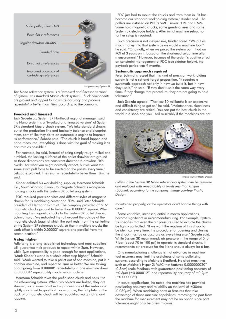
The Nano reference system is a “tweaked and finessed version” of System 3R’s standard Macro chuck system. Chuck components are ground and lapped to maximize accuracy and produce repeatability better than 1μm, according to the company.
Image courtesy System 3R.
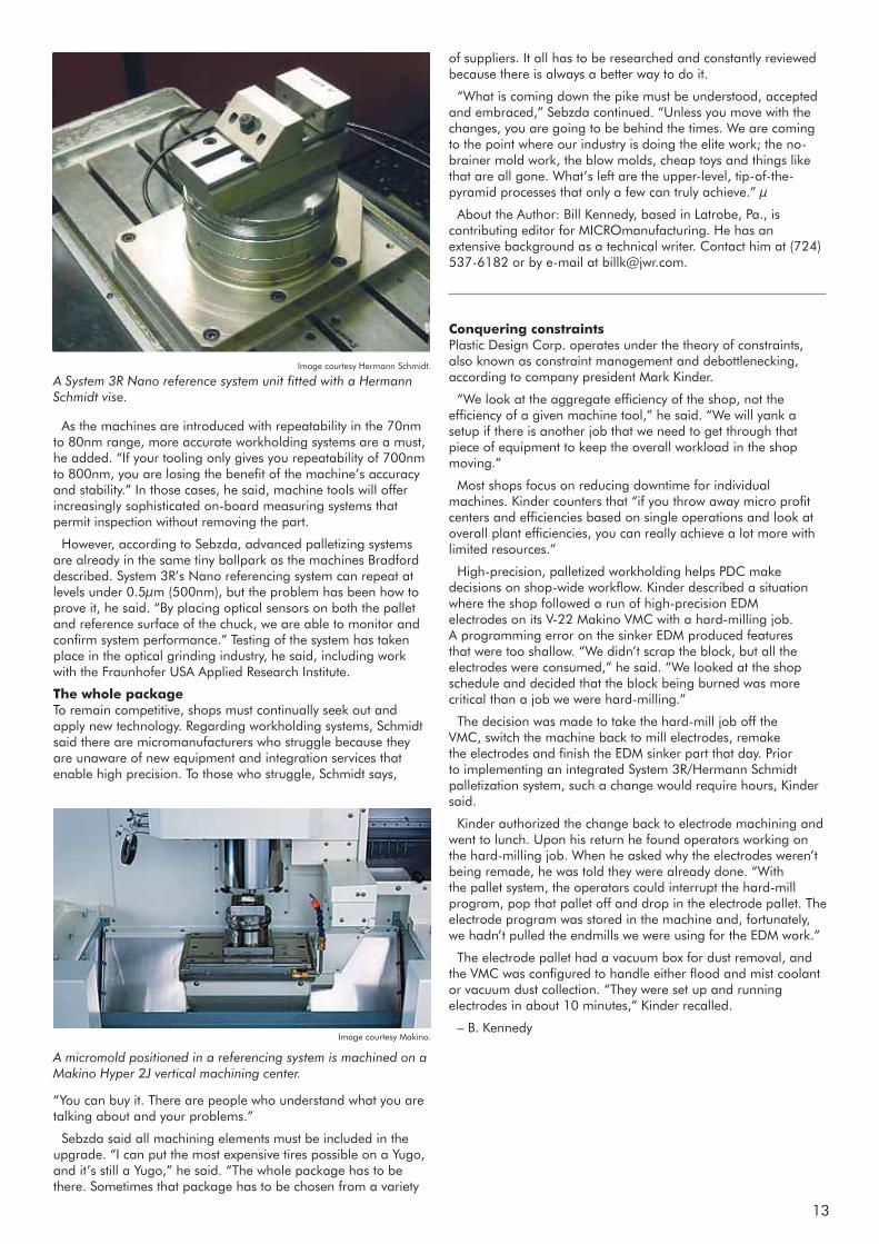
Pallets in the System 3R Nano referencing system can be removed and replaced with repeatability at levels less than 0.5μm (500nm), according to the company. Image courtesy Plastic Design.
Image courtesy Plastic Design.
maintained properly, or the operators don’t handle things with care.”
Some variables, inconsequential in macro applications, become significant in micromanufacturing. For example, System 3R specifies that even the air pressure used to actuate the chucks be tightly controlled. “If we want the reaction of this chuck to be identical every time, the procedure for opening and closing the chuck must be as accurate as everything else,” Sebzda said. While System 3R recommends air pressure in the range of 5 to 7 bar (about 70 to 100 psi) to operate its standard chucks, it recommends air pressure for the Nano should always be 6 bar.
One manufacturing challenge is that advances in machine tool accuracy may limit the usefulness of some palletizing systems, according to Makino’s Bradford. He cited machines such as Makino’s Hyper 2J VMC that features 0.000000020” (0.5nm) scale feedback with guaranteed positioning accuracy of ±0.3μm (±0.000012”) and repeatability accuracy of ±0.2μm (±0.000008”).
In actual applications, he noted, the machine has provided positioning accuracy and reliability on the level of ±30nm (0.030μm). When machining parts or features that take advantage of those machine capabilities, removing the part from the machine for measurement may not be an option since part tolerance might only be a few microns.
Solid pallet, 3R-651-N
Extra flat z-references
Regular drawbar 3R-605.1
Improved accuracy of carbide xy-references
Grinded hole
Extra flat z-references
13
A System 3R Nano reference system unit fitted with a Hermann Schmidt vise.
As the machines are introduced with repeatability in the 70nm to 80nm range, more accurate workholding systems are a must, he added. “If your tooling only gives you repeatability of 700nm to 800nm, you are losing the benefit of the machine’s accuracy and stability.” In those cases, he said, machine tools will offer increasingly sophisticated on-board measuring systems that permit inspection without removing the part.
However, according to Sebzda, advanced palletizing systems are already in the same tiny ballpark as the machines Bradford described. System 3R’s Nano referencing system can repeat at levels under 0.5μm (500nm), but the problem has been how to prove it, he said. “By placing optical sensors on both the pallet and reference surface of the chuck, we are able to monitor and confirm system performance.” Testing of the system has taken place in the optical grinding industry, he said, including work with the Fraunhofer USA Applied Research Institute.
The whole package To remain competitive, shops must continually seek out and apply new technology. Regarding workholding systems, Schmidt said there are micromanufacturers who struggle because they are unaware of new equipment and integration services that enable high precision. To those who struggle, Schmidt says,
of suppliers. It all has to be researched and constantly reviewed because there is always a better way to do it.
“What is coming down the pike must be understood, accepted and embraced,” Sebzda continued. “Unless you move with the changes, you are going to be behind the times. We are coming to the point where our industry is doing the elite work; the no-brainer mold work, the blow molds, cheap toys and things like that are all gone. What’s left are the upper-level, tip-of-the-pyramid processes that only a few can truly achieve.” μ
About the Author: Bill Kennedy, based in Latrobe, Pa., is contributing editor for MICROmanufacturing. He has an extensive background as a technical writer. Contact him at (724) 537-6182 or by e-mail at [email protected].
Conquering constraints Plastic Design Corp. operates under the theory of constraints, also known as constraint management and debottlenecking, according to company president Mark Kinder.
“We look at the aggregate efficiency of the shop, not the efficiency of a given machine tool,” he said. “We will yank a setup if there is another job that we need to get through that piece of equipment to keep the overall workload in the shop moving.”
Most shops focus on reducing downtime for individual machines. Kinder counters that “if you throw away micro profit centers and efficiencies based on single operations and look at overall plant efficiencies, you can really achieve a lot more with limited resources.”
High-precision, palletized workholding helps PDC make decisions on shop-wide workflow. Kinder described a situation where the shop followed a run of high-precision EDM electrodes on its V-22 Makino VMC with a hard-milling job. A programming error on the sinker EDM produced features that were too shallow. “We didn’t scrap the block, but all the electrodes were consumed,” he said. “We looked at the shop schedule and decided that the block being burned was more critical than a job we were hard-milling.”
The decision was made to take the hard-mill job off the VMC, switch the machine back to mill electrodes, remake the electrodes and finish the EDM sinker part that day. Prior to implementing an integrated System 3R/Hermann Schmidt palletization system, such a change would require hours, Kinder said.
Kinder authorized the change back to electrode machining and went to lunch. Upon his return he found operators working on the hard-milling job. When he asked why the electrodes weren’t being remade, he was told they were already done. “With the pallet system, the operators could interrupt the hard-mill program, pop that pallet off and drop in the electrode pallet. The electrode program was stored in the machine and, fortunately, we hadn’t pulled the endmills we were using for the EDM work.”
The electrode pallet had a vacuum box for dust removal, and the VMC was configured to handle either flood and mist coolant or vacuum dust collection. “They were set up and running electrodes in about 10 minutes,” Kinder recalled.
– B. Kennedy
Image courtesy Hermann Schmidt.
A micromold positioned in a referencing system is machined on a Makino Hyper 2J vertical machining center.
Image courtesy Makino.
“You can buy it. There are people who understand what you are talking about and your problems.”
Sebzda said all machining elements must be included in the upgrade. “I can put the most expensive tires possible on a Yugo, and it’s still a Yugo,” he said. “The whole package has to be there. Sometimes that package has to be chosen from a variety

14
Less than one thousandth of a millimetre
Tool for sun-focusing lenses – Fresnel part on bottom and a lens array at the top.
Fresnel lens
Lens array
System 3R’s MatrixNano has met all our high expectations...
Kunihiko Haga & Keiichi Kojima – visibly pleased with the Matrix pallet system.
Kyoei Engineering K.K. is famous for its expertise in manufac turing high quality moulding tools, prototypes and precision components.
Its customers are mainly from:
• The optical industry (with its nano-machining of moulding tools and parts for light plates and lenses).
• The aerospace industry (with its milling of “difficult” materials such as titanium and Inconel).
• The automotive industry.
The end customers’ extremely high demands in respect of preci-sion have led to Kyoei Engineering having a long collabora-tion with System 3R. To guarantee Kyoei Engineering’s capacity to produce the required precision, a wide spectrum of pallet systems (Macro, MacroMagnum, Delphin and GPS240) with and without vibration damping have been supplied.
One example of Kyoei Engineering’s operations is the ma-nufacture of moulding tools for Fresnel lenses. This is certainly not run-of-the-mill production. A Fresnel lens has “saw-tooth” microgrooves that refract the light in, for example, solar energy collectors.
Case – Koyei Engineering K.K
15
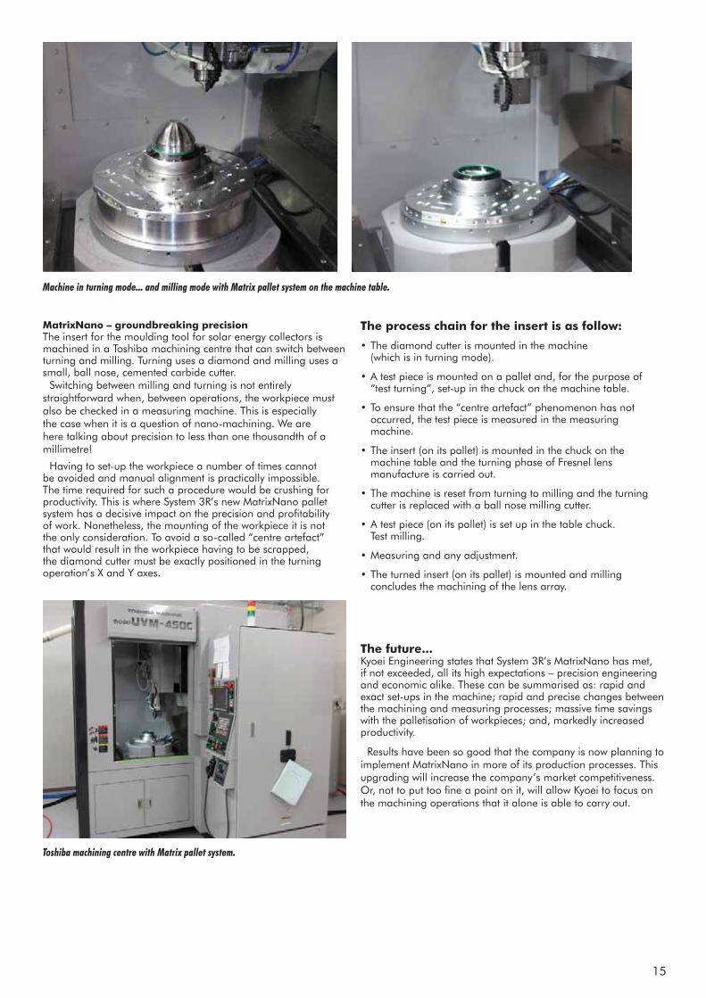
Machine in turning mode... and milling mode with Matrix pallet system on the machine table.
Toshiba machining centre with Matrix pallet system.
The process chain for the insert is as follow:
• The diamond cutter is mounted in the machine (which is in turning mode).
• A test piece is mounted on a pallet and, for the purpose of “test turning”, set-up in the chuck on the machine table.
• To ensure that the “centre artefact” phenomenon has not occurred, the test piece is measured in the measuring machine.
• The insert (on its pallet) is mounted in the chuck on the machine table and the turning phase of Fresnel lens manufacture is carried out.
• The machine is reset from turning to milling and the turning cutter is replaced with a ball nose milling cutter.
• A test piece (on its pallet) is set up in the table chuck. Test milling.
• Measuring and any adjustment.
• The turned insert (on its pallet) is mounted and milling concludes the machining of the lens array.
The future... Kyoei Engineering states that System 3R’s MatrixNano has met, if not exceeded, all its high expectations – precision engineering and economic alike. These can be summarised as: rapid and exact set-ups in the machine; rapid and precise changes between the machining and measuring processes; massive time savings with the palletisation of workpieces; and, markedly increased productivity.
Results have been so good that the company is now planning to implement MatrixNano in more of its production processes. This upgrading will increase the company’s market competitiveness. Or, not to put too fine a point on it, will allow Kyoei to focus on the machining operations that it alone is able to carry out.
MatrixNano – groundbreaking precision The insert for the moulding tool for solar energy collectors is machined in a Toshiba machining centre that can switch between turning and milling. Turning uses a diamond and milling uses a small, ball nose, cemented carbide cutter.
Switching between milling and turning is not entirely straightforward when, between operations, the workpiece must also be checked in a measuring machine. This is especially the case when it is a question of nano-machining. We are here talking about precision to less than one thousandth of a millimetre!
Having to set-up the workpiece a number of times cannot be avoided and manual alignment is practically impossible. The time required for such a procedure would be crushing for productivity. This is where System 3R’s new MatrixNano pallet system has a decisive impact on the precision and profitability of work. Nonetheless, the mounting of the workpiece it is not the only consideration. To avoid a so-called “centre artefact” that would result in the workpiece having to be scrapped, the diamond cutter must be exactly positioned in the turning operation’s X and Y axes.
16
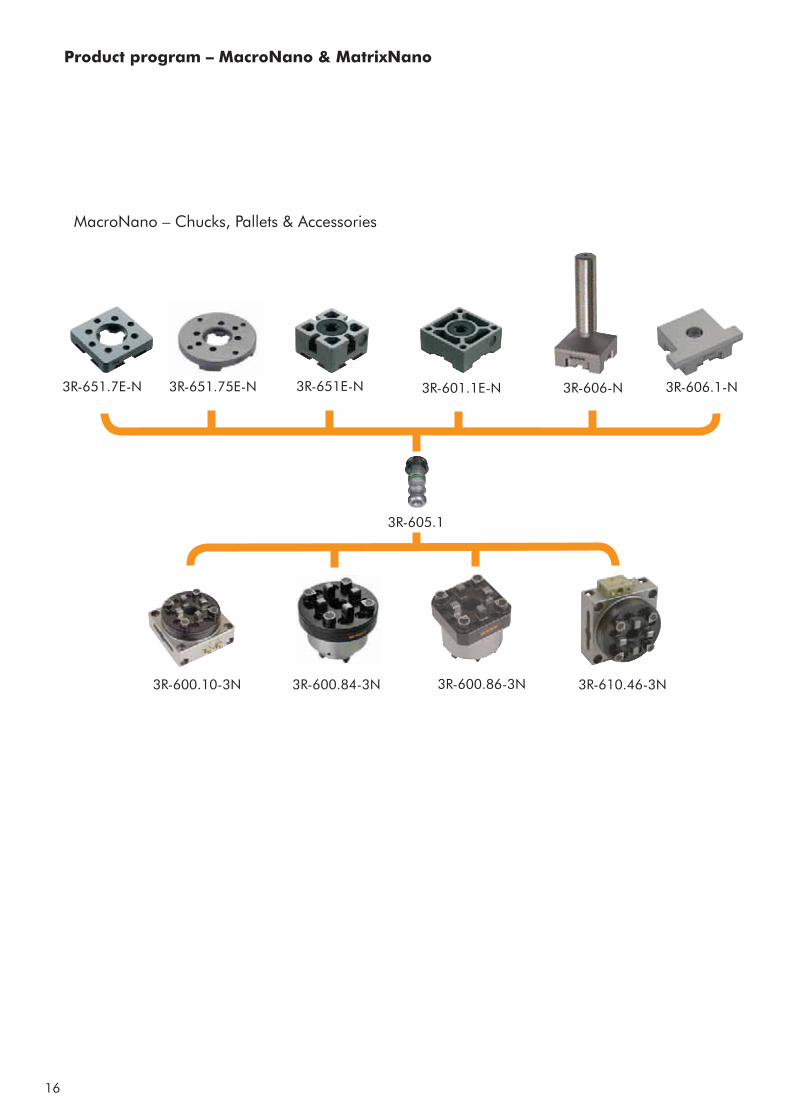
3R-651.7E-N 3R-651.75E-N 3R-651E-N 3R-601.1E-N 3R-606-N 3R-606.1-N
3R-605.1
3R-600.84-3N 3R-600.86-3N3R-600.10-3N 3R-610.46-3N
MacroNano – Chucks, Pallets & Accessories
Product program – MacroNano & MatrixNano
17
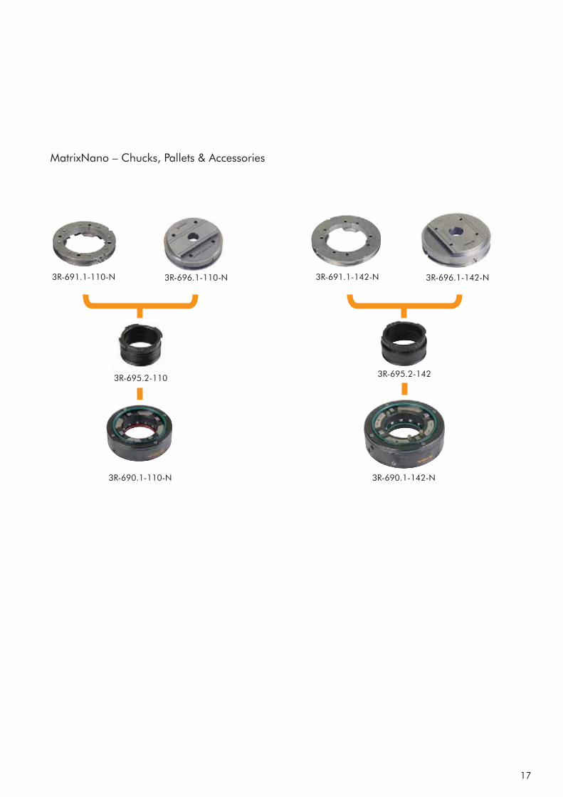
3R-691.1-110-N 3R-696.1-110-N
3R-690.1-110-N
3R-695.2-110
3R-691.1-142-N 3R-696.1-142-N
3R-690.1-142-N
3R-695.2-142
MatrixNano – Chucks, Pallets & Accessories
18
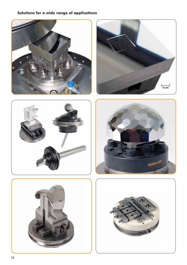
Solutions for a wide range of applications

System 3R International ABSorterargatan 1, 162 50 VÄLLINGBYtel +46-08 620 20 00, fax +46-08 759 52 34, e-mail: [email protected], www.system3r.com
System 3R Europe GmbH
tel +49 61 52 80 02 0fax +49 61 52 80 02 35
Chech Republic & SlovakiaSystem 3R Czech
tel +420 234 054 224fax +420 234 054 225e-mail: [email protected]
France & PortugalSystem 3R France
tel +33-01 60 95 90 80fax +33-01 60 37 88 16e-mail: [email protected]
Germany & BeNeLuxSystem 3R Deutschland
tel +49 61 52 80 02 0fax +49 61 52 80 02 35
Italy & SpainSystem 3R Italia
tel +39 02 92 38 821fax +39 02 92 11 23 19e-mail: [email protected]
ScandinaviaSystem 3R NordicSorterargatan 1SE-162 50 VÄLLINGBYtel +46-08 620 20 00fax +46-08 759 52 34e-mail: [email protected]
Järfälla Härdverkstad
tel +46-08 580 125 50fax +46-08 580 126 55
Switzerland & AustriaSystem 3R Schweiz AG
tel +41-071 394 13 50fax +41-071 394 13 60e-mail: [email protected]
TurkeySystem 3R Türkiye
tel +90-212 613 8062-8063fax +90-212 613 8069
United KingdomSystem 3R UK
tel +44-02476 538653fax +44-02476 538695
System 3R USA Inc.
tel +1 847 439 4888fax +1 847 439 5099
Canada & MImobile +1 519 870 8339fax +1 847 439 5099
AZ, CA, CO, ID, MT, NM, NV, OR, UT, WA, WY & Mexicomobile +1 714 299 4923fax +1 847 439 5099
IA, MN, ND, NE, SD & Western WImobile +1 612 963 6904fax +1 847 439 5099
AR, IN, KY, OH, TN, MO, KS, OK & Southern ILmoblie +1 317 694 7508fax +1 847 439 5099
AL, FL, GA, LA, MS, NC, SC & TXmobile +1 813 326 0125fax +1 847 439 5099
Nothern IL & Eastern WImobile +1 847 400 6073fax +1 847 439 5099
NJ, NY & PAmobile +1 201 248 3885fax +1 847 439 5099
CT, DC, DE, MA, MD, ME, NH, RI, VA, VT & WVmobile +1 201 214 7088fax +1 847 439 5099
www.system3r.com
India, SE-Asia & AustraliaSystem 3R Far East Pte.Ltd.
tel +65-6289 4811fax +65-6289 3011e-mail: [email protected]
China, Taiwan & Hong Kong System 3R Shanghai Co Ltd
tel +86-21 6432 7927fax +86-21 6432 7928e-mail: [email protected]
tel +86-10 8225 1632fax +86-10 8225 1635
tel +86-769 8162 0628fax +86-769 8162 0638
tel +886-02 2278 3126fax +886-02 2278 3108
Japan & KoreaSystem 3R Japan CO., Ltd.
tel +81 3-6906-7077fax +81 3-6906-7575
tel +81-052 774 6250fax +81-052 774 6285