Embed Size (px)
Citation preview
Ultralight Modular Robotic Building Blocks for the Rapid Deployment ofPlanetary Outposts
Mustafa Emre Karagozler, Brian Kirby, Wei Jie Lee, Eugene Marinelli,Tze Chang Ng, Michael Philetus Weller, Seth Copen Goldstein
Carnegie Mellon University5000 Forbes AvenuePittsburgh, PA 15213
Abstract
We examine how modular robots can be used to enable remote robotic construction of planetary and orbital outposts.Each modular robot, called acatom, contains sufficient actuation, adhesion, control, and power to allow it to functionas part of an ensemble of similar units. We describe the catom design and construction as well as initial experimentscarried out to verify the system.
1 Introduction
The President’s Space Exploration Initiative calls for NASA to undertake several manned missions to establish outpostson the moon and Mars. NASA’s plan calls for sending robotic missions ahead of astronauts to both the moon and Marsto establish automated facilities for gathering in-situ resources such as fuel, water and oxygen. Establishing thesefacilities before astronauts arrive reduces the amount of material that must be brought from earth and lowers the riskof missions by providing the potential to generate resources to meet unforeseen needs after astronauts have arrived.
These robotic missions will need a variety of structures, including warehouses to accommodate robotic factories,provide storage for the resources they generate, and living spaces both on the surface and in orbit to house the crewwhen they arrive. Providing lightweight, deployable buildings to send on these missions to bootstrap the on-sitemanufacturing operations presents a significant design challenge. Structural systems tend to be large and heavy,making them expensive to launch into orbit. The robotic assembly mechanism for these seed structures must beextremely robust as their failure to deploy could jeopordize the entire mission. The building system used to supportplanetary outposts should also be flexible to allow for the accomodation of unforseen circumstances that could arisein the interval between when a robotic mission is launched and actually arrives on Mars.
We propose here a lightweight construction system to allow the rapid and autonomous deployment of planetaryfacilities on the moon and Mars, based on modular robotics technologies we are currently developing [?]. A roboticfactory and a supply of lightweight materials would be shipped from earth with each robotic mission to establish a newplanetary outpost. Once on-site the robotic factory would begin constructing modular robotic building blocks fromthese materials. After a sufficient number of blocks have been generated the site plan for the outpost would be sentto the blocks, and the blocks would autonomously assembly themselves into the required structures. This assemblyprocess is very robust due to the high degree of redundancy of the robotic building blocks, and structures composedof blocks have the capability for self-healing parts of the structure that are damaged by simply replacing the damagedportion of the structure with spare block modules.
This project is an outgrowth of the claytronics project at Carnegie Mellon University. The claytronics project isstudying how to build and program massive ensembles of microscale modular robots (calledcatomsfor claytronicatoms) to form arbitrary three dimensional objects. Each catom is a self-contained robotic module capable of com-puting, communicating, cooperative movement and adhesion between neighboring modules, as well as storing anddelivering power. The catoms described in this paper are loosely based on, but scaled-up versions of, the microscalecatoms being developed for claytronics.
1
2 Use Scenario
2.1 Advantages of Modular Robotics
One class of modular robots are systems comprised of an ensemble of homogeneous robotic modules. Each individualmodule is fairly simple and only needs to provide enough actuation, sensing and processing capability to support thefunctionality of the entrire ensemble [?]. Modular robotics technology has several properties that make it ideally suitedfor space and planetary applications: lightness and compactness, robustness and adaptability and versatility [?].
Our ultralight modular robotic building blocks can provide an extremely compact building sytem as there arepotentially two stages of expansion. Compactly packaged materials and subassemblies would be assembled into fullmodules on site; once the modules are assembled they expand from a solid lattice to enclose a volume. The individualmodules are built with carbon fiber frames, which provide a great deal of structural support with very little weight.
Modular robotics systems are able to provide highly robust and adaptive performance with large numbers of rela-tively inexpensively manufactured modules, much like the systems proposed by Brooks for unmanned interplanetaryexploration[?]. As long as there are sufficient numbers of modules available, failed modules can simply be replacedto allow an ensemble of modules to continue to function properly.
Here we present several specific use scenarios to illustrate the flexibility of our proposed structural system.
2.2 Orbital Space Station
Orbiting space stations allow astronauts to shuttle back and forth from the surface of the planet and catch a ride onan interplanetary vehicle without requiring it to negotiate landing and takeoff, and to provide a safe haven in case ofthe failure of systems on the surface. Our robotic building blocks could be used to generate space station modulesthat could expand to accomodate changing numbers of astronauts present, and automatically repair damaged areas.When a robotic mission vehicle arrived at a planet, it could send some modules to the surface, but remain in orbit toprovide core life support and communications systems for an orbital space station. An onboard robotic factory wouldthen begin to assemble robotic blocks, which would reconfigure themselves to generate additional modules attachedto the original seed to provide space for astronauts and the storage of resources generated on the surface. The wallsof each module would be composed of several layeres so that damage could quickly be repaired by spare modules inthe outside layers. Once surface manufacturing facilities began to produce resources, the robotic shuttle could bringwater and oxygen up from the surface. The inner layers of the modular robotic blocks could then be filled with waterto provide a radiation barrier for the crew, and oxygen could be used to generate a breathable atmosphere.
2.3 Surface Warehouses
Our robotic blocks could also be used to generate warehouse structures to house surface manufacturing operationsand provide a dust free, controlled environment for various manufacturing processes, as well as storage of resourcesproduced by these processes. As new resources are discovered in different areas of the lunar or martian surface, thesestructures could be quickly taken down and redeployed, allowing robotic missions to respond quickly to informationdiscovered by exploration and efficiently reuse structural components.
2.4 Surface Living Quarters
Living quarters could be erected using blocks prior to the arrival of a crew to decrease the risk of requiring a crew toassemble their own living quarters upon their arrival. A site plan for the living spaces could be generated on site to takegeological formations into account, and a series of airtight modules with multilayered walls could be assembled by agroup of blocks. Like the orbital station, the interior layer of modules could be filled with water to protect the crewfrom radiation. As the number of crew members present at the outpost changed, the structure could be reconfigured toaccommodate them.
2.5 Architectural Robotics
As proposed by Weller in [?] architectural robotic systems composed of modular robotic building blocks could usethe space available in surface or orbital crew quarters more efficiently than static structural systems. Instead of havingto provide a wide variety of spaces customized for specialized uses such as kitchens and bedrooms, which are only
2

occupied serially at different times of the day, an architectural robotic space could reconfigure itself to provide a largekitchen and dining area at mealtime and then individual bedrooms for crew members in the same space afterwards. Inthis manner crew quarters built from our robotic blocks could more comfortably accomodate a greater number of crewmembers in a smaller space while utilizing less structural resources.
2.6 Scaffold for Cross-linked Polymer Resin Bunkers
The block modules could also be used as a scaffold for the creation of more permanent structures. A group of modulescould be used to fill a space of the desired shape, and then a release agent could be sprayed onto the structure followedby a cross-linked polymer resin mixed [?] with the local soil to create a concrete-like shell. The advantage of thissystem is that the local soil makes up over 80% of the weight of the final product, so only 20% ofthe weight needsto be transported. Once this shell reached full structural strength, the robotic building blocks could disassemble thescaffold structure and be reused. The concrete-like shell could be covered with soil to provide a more robust andradiation-proof space for either crew housing or long-term storage of resources and equipment.
3 Design Considerations for a Modular Robotic Building Block for Plane-tary Outposts
Our group has proposed that modular robotic modules should be designed according to the Ensemble Axiom: a singlemodule should provide no more functionality than necessary to generate the desired behavior of the ensemble [?]. Inthis section we discuss some of the factors that the design of our ultralight robotic building block module will needto accomodate to allow a group of blocks to function to generate the structures we proposed in the previous section.We will further discuss the desired properties of an ensemble of robotic blocks and the particular design decisions wehave made for the individual block modules in later sections.
3.1 Form Factor
While there are several types of modular robots, lattice type modules are particularly well suited to structural applica-tions. There are several different form factors that have been proposed for lattice type modules, including a rotatingsphere, as in Claytronics modules [?], and an expanding cube such as Rus and Vona’s Crystalline Atom [?] and PARC’sTelecubes [?]. We have chosen to develop a novel hybrid of these two form factors, the cubic rotating module. Theadvantages of this form factor are that we are able to use an actuation mechanism that is more lightweight and compactthan is necessary for expanding cubes, while we need fewer actuators than would be required for a shape with morefacets like the catoms. The cubic modules pack tightly into a lattice (with no gaps between modules). This lends itselfeasily to generating flat surfaces that are typical of buildings. Individual modules have sufficient degrees of freedomto reach any location on the surface of a group of blocks, simplifying reconfiguration planning.
3.2 Actuation
One of our goals it to support reconfiguration of a group of modules into arbitrary structures. This requires thateach module have a rich set of movements. There is a tradeoff between the mechanical complexity, actuation forcesrequired, degrees of freedom, and planning complexity. To be able to place a module anywhere on the surface of agroup of modules, each module must have actuators capable of at least lifting the module itself, and possibly mighthave to be able to lift itself and another module or two. In the Claytronics planar prototype, a module can reach anylocation on the perimeter of a group of modules by rolling just itself across neighboring modules using an array of24 electromagnets [?]. ATRON modules, in contrast, have only one actuator per module, but that actuator must bepowerful enough to move two other modules to achieve enough degrees of freedom to be able to place a module in anarbitrary location on the surface of a group of modules [?]. Our cubic catom modules are capable of rotating alongany edge adjacent to another module. This requires at least 4 actuated flaps per face, but simplifies planning and themechanical forces needed, as only one module needs to be moved at a time.
3
3.3 Control / Communication
It is generally necessary to have a mechanism for local communication between neighboring latched modules, asbroadcast wireless communications do not work well through dense lattices of modules. Depending on the complexityof the control system modules can either communicate just with their neighbors to discover the local topology, or canhave a more complex message routing scheme to allow messages to be sent to any module in the group through localconnections. More complex connector hardware, such as a dedicated pair of electrical contacts for communicationin each latch, can simplify the routing of messages, but can make latching and unlatching modules more complex.Routing both power and communication through unary connectors makes the control problem more complex butmakes latching and unlatching simpler and more robust [?].
3.4 Power
As modules are to be remotely deployed, it is important that they are able to route power from a central source tobe able to recharge their onboard batteries. We have researched a variety of algorithms for routing power throughunary or binary power connectors in [?]. While these adaptive power routing algorithms place extra processing andmessaging demands on the modules, they can significantly increase the robustness of the entire ensemble by preventingany modules from being starved for power.
3.5 Adhesion
There are a variety of mechanisms that have been proposed to latch modules to their neighbors. They fall generallyinto two classes: mechanical connectors, like the ATRON module [?] and magnetic or electromagnetic connectorssuch as the Telecubes [?] and our catom modules [?]. The advantage of mechanical latches is that they tend to be verystrong, but they are complex to build and prone to binding under load. Magnetic latches help align connectors duringlatching but tend to provide less adhesive force. Additionally, permanent latching connectors like the Telecube’s canbe difficult to control and do not turn all the way off, complicating unlatching, while electromagnetic latches like ourcatom module’s draw power even when sitting still.
We have developed a novel latching system for our robotic building blocks, which relies on electrostatic inductionto adhere two flaps to one another. This mechanism has advantages similar to an electromagnetic latch, but draws verylittle power once latched. We intend to further develop our mechanism to allow the creation of an airtight seal betweenmodules to allow the support of a breathable atmosphere in space and on the lunar and martian surfaces.
3.6 Environmental Constraints
There are a variety of different environmental constraints that our robotic building blocks would have to addressdepending on whether they are deployed in space or on the lunar or martian surface. We discuss here a few of theseconstraints that we believe are particularly relevant, although there are many more that would need to be considered.
3.6.1 Radiation
All of the environments we are considering are frequently exposed to dangerous levels of radiation. To protect sensitivemanufacturing equipment or members of the crew we intend to allow our modules to be filled with water generated onsite to create a radiation barrier.
3.6.2 Air Density
As none of the environments we are considering has an air density suitable for a breathable atmosphere it will benecessary for modules to be able to generate airtight pressurized spaces that can be filled with oxygen and nitrogengenerated by surface resource processing.
Air density is also critical for convective cooling of electronics and actuators. Low atmospheric densities couldrequire active cooling of these components.
4
3.6.3 Gravity
In our experiments that we have performed we have filled our robotic building blocks with helium to simulate verylow gravity conditions similar to those encountered in orbit. However more robust actuation mechanisms could benecessary to provide enough power on the martian and lunar surfaces, as although there is gravitational force on Mars,very little lift can be generated by displacing the thin atmosphere with helium. Similarly there is even less gravitationalforce on the moon, but there is no atmosphere to be displaced.
3.6.4 Wind
As our ultralight robotic building blocks have very little mass and a great deal of surface area, they are somewhat sen-sitive to wind. Although the Martian surface frequently experiences winds of up to 300 miles per hour the atmosphereis much less dense, and so would exert less force than wind here.
3.6.5 Dust
Lunar and particularly windblown Martian dust can create problems for a variety of mechanisms, including solar cells.Our electrostatic inductive latching flaps could be particularly severely impacted as static forces on the flaps wouldtend to cause dust to adhere to the surface. We intend to investigate mechanisms to prevent the buildup of dust on therobotic building block’s flaps.
4 Related Work
There has been a great deal of research into the feasibility of building lattice type modular robotics systems. Rusand Vona’s Crystalline Modules [?] and PARC’s Telecubes [?] demonstrated the potential of expanding lattice typemodules. The Crystalline Atom, although it only reconfigured in two dimensions, demonstrated that an ensembleof lattice type modules could be programmed to generate any arbitrary shape, but its mechanical latches had issueswith binding and its actuation mechanism was not powerful enough to function in 3D. The Telecubes were a fully3D crystalline expanding module, and replaced the Crystalline Atoms’ mechanical latches with switching permanentmagnets, and used a fairly complex and expensive actuation system to produce enough power to lift the weight of themodule itself and another module.
More recently several rotating lattice type modules have been developed, notably the Adaptronics group’s ATRONmodule [?] and our catom module [?]. ATRON modules only have one motion actuator per module, simplifying eachmodule and leaving room for a robust mechanical latching system. However the limited degrees of freedom of themodule make it difficult to plan to reach an arbitrary position. Like the Telecubes, our catom modules have a fairlylarge number of actuators, but each actuator needs to provide less power as it only needs to rotate one module a smallangle. The other innovative feature of our catoms is their unary electromagnetic latching system that allows modulesto very quickly latch and unlatch.
There have been several proposals to leverage modular robotics technology for space exploration. Modular roboticsresearchers at PARC have suggested that the ability to reuse the same components for different applications rather thanhaving to launch a new design into space every time needs change make modular robotics ideal for space applications[?]. Shen, Will and Khoshnevis describe a self-assembling structural system for reconfigurable satellites that wouldobviate the need to launch new structural components into space for every new satellite, as parts from defunct satellitesalready in orbit could be reused [?].
Although we do not discuss the details of our high-level control system to achieve recongfiguration here, our grouphas developed a distributed, parallelized algorithm to support reconfiguration between arbitrary shapes, based on therandom motion of ”hole” metamodules in the interior of the ensemble [?]. Also relevant is Stoy and Nagpal’s 3D,distributed, parallelized control system for rotating lattice type cubes described in [?].
5 Proposed Design
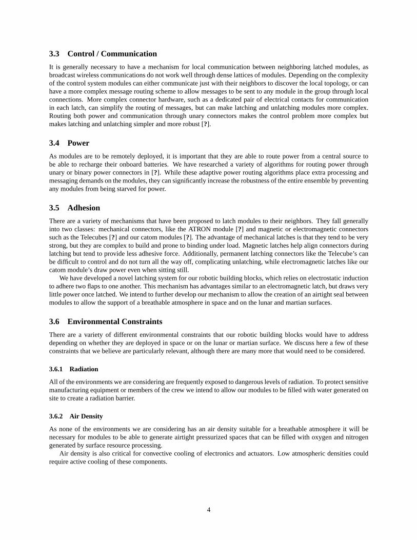
Our reconfigurable structural system will be composed of cubic catoms with four triangular actuated flaps on eachface. These catoms will be able to rotate around each other by extending a flap to the next face of a neighboring cubeand releasing the flap latched to the current face as in Figure??.
5
Figure 1: Illustration of one catom rotating around another catom and two of the constructed catoms sitting on top ofeach other.
The ultimate goal for this system is an adaptive, scalable, and robust control system that coordinates itself in adistributed fashion based on high-level global demands. An earth-based or preprogrammed goal model would be set,and then the catoms would interact locally to construct the model. The software would adapt around local failures andscale from a few modules to thousands or millions without any emergent problems.
For shipping the catoms on interplanetary missions subassemblies consisting of two flaps and the associated in-ternal structure would be tightly packed to conserve space. Upon arrival a robotic factory would assemble thesesubassemblies into complete catoms. The newly constructed catoms would then be sent directions from the centralplanner on board the probe to reconfigure into structures as needed to support mission activities. This system wouldallow an expansion of roughly two orders of magnitude from the space required on the probe vehicle to space enclosedby the system. This efficiency is further compounded by the ability to reuse the structure for other purposes.
5.1 Actuation
Each catom requires 24 moveable flaps for complete mobility. Our current system actuates and controls each flapindependently using a composite shape memory alloy (SMA) / spring system shown in Figure??. The SMA contractsas it is heated, lifting the flap via a pulley. As it cools, a constant force spring slowly closes the flap and returns theSMA to its initial length. The benefit of this system is that it closely mimics the microscale actuation of a bimorphheater, implying significant flexibility in catom sizing. One downside is that heating the SMA requires a high currentpower source and substantial wiring. More troubling is that reverse actuation is at the mercy of convective cooling.
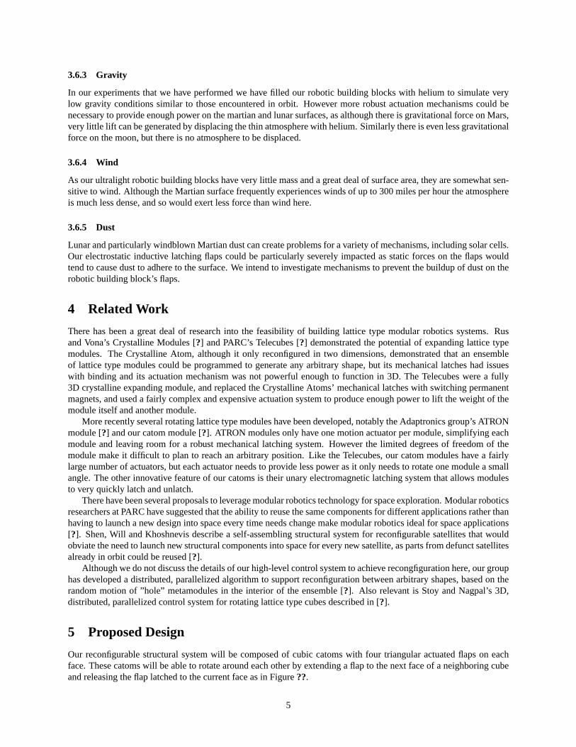
Other designs that we are considering include replacing the SMA / spring composite system with a low currentmotor with a non-backdrivable, reversible gearbox. This will lower the overall current and wiring requirements andequalize the time durations opening and closing the flap. Additionally, it gives us great torque flexibility, permittingus to sacrifice speed for lifting strength limited only by the mechanical strength of the structure. This will be very
6
Figure 2: Torque required to lift 10cm, 2kg catoms on Mars. The net torque is the sum of the torque needed to actuatethe flap and the torque needed to lift the cube.
helpful in an environment like Mars, where the weight of the robot must be handled by the actuator. This can be seenin Figure??.
Another actuation design that we are pursuing is mechanically linking the four flaps on each of the six faces. Thismeans that all four flaps on a face must open together, but also means that we require only six independent actuators.While this constrains some motions, such as moving on a non-catom surface, it still allows full intercatom mobility.This mechanism would be applicable whether we used our SMA/spring composite, gearhead motors, or other system.
5.2 Power
The simplest solution to satisfy the power requirements of catoms would be to individually power each catom by usingon board batteries. However, this configuration has many disadvantages when a Martian exploration mission is con-sidered. The main disadvantage is that batteries require recharging/replacement, which increases the costs drastically,and also requires external maintenance staff/machinery. When considering the challenges of such a mission, designingthe system in a way that avoids such maintenance is crucial.
Our proposed solution is to make catoms deliver power to each other. In this case, catoms only store a limitedamount of power in an internal battery that is enough to move them for a limited time until they establish contact witha group of other catoms, that has a power source. The power source is either a high capacity and stationary battery or agroup of specialized catoms that have power scavenging mechanisms such as solar cells. As the contact is establishedwith the group, the catom is powered through this contact, and the internal rechargeable battery is charged.
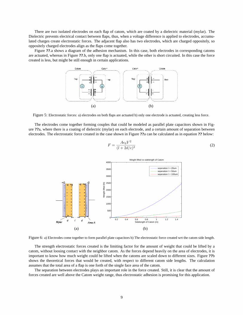
Catoms make use of electrodes mounted on the flaps to create electrostatic forces that enable them to adhere toeach other. An important property of the electrodes is that they provide capacitive coupling between catoms, whichallows power transfer through an alternative excitation. In our proposed solution, catoms deliver power to each otherusing capacitive coupling with alternative currents (AC). The AC power generated at the neighboring catom is thenrectified and regulated, and the resulting DC power is used for processing and other electronics (Figure??a).
An estimation of the efficiency of power transfer can be made based on the capacitive coupling between catoms.Figure??b shows the equivalent circuit of the system, where resistance R represents the input resistance of the rectify-ing and regulating circuitry (assumed to be purely resistive). The ratio ofVR/V can be considered as a good estimateof efficiency. Then equation?? is:
VR =V R
R + 2/jωC, |VR| = |V | RωC√
R2ω2C2 + 4(1)
7
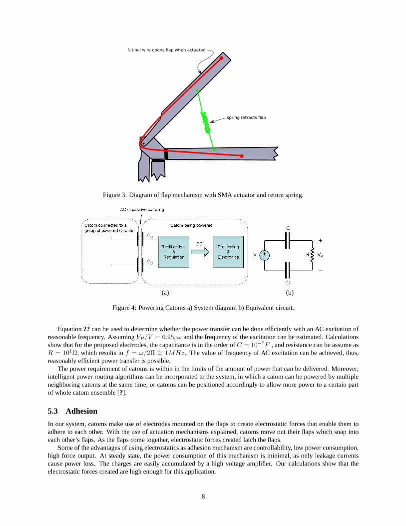
Figure 3: Diagram of flap mechanism with SMA actuator and return spring.
(a) (b)
Figure 4: Powering Catoms a) System diagram b) Equivalent circuit.
Equation?? can be used to determine whether the power transfer can be done efficiently with an AC excitation ofreasonable frequency. AssumingVR/V = 0.95, ω and the frequency of the excitation can be estimated. Calculationsshow that for the proposed electrodes, the capacitance is in the order ofC = 10−7F , and resistance can be assume asR = 101Ω, which results inf = ω/2Π ∼= 1MHz. The value of frequency of AC excitation can be achieved, thus,reasonably efficient power transfer is possible.
The power requirement of catoms is within in the limits of the amount of power that can be delivered. Moreover,intelligent power routing algorithms can be incorporated to the system, in which a catom can be powered by multipleneighboring catoms at the same time, or catoms can be positioned accordingly to allow more power to a certain partof whole catom ensemble [?].
5.3 Adhesion
In our system, catoms make use of electrodes mounted on the flaps to create electrostatic forces that enable them toadhere to each other. With the use of actuation mechanisms explained, catoms move out their flaps which snap intoeach other’s flaps. As the flaps come together, electrostatic forces created latch the flaps.
Some of the advantages of using electrostatics as adhesion mechanism are controllability, low power consumption,high force output. At steady state, the power consumption of this mechanism is minimal, as only leakage currentscause power loss. The charges are easily accumulated by a high voltage amplifier. Our calculations show that theelectrostatic forces created are high enough for this application.
8
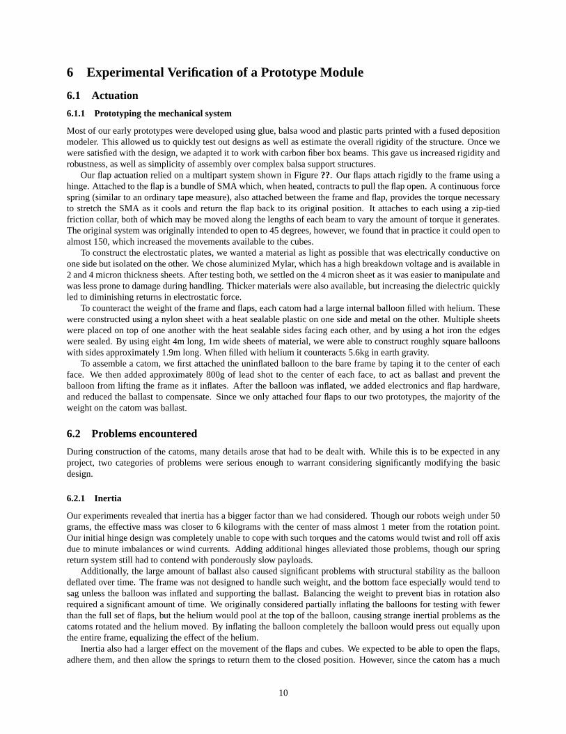
There are two isolated electrodes on each flap of catom, which are coated by a dielectric material (mylar). TheDielectric prevents electrical contact between flaps, thus, when a voltage difference is applied to electrodes, accumu-lated charges create electrostatic forces. The adjacent flap also has two electrodes, which are charged oppositely, sooppositely charged electrodes align as the flaps come together.
Figure??.a shows a diagram of the adhesion mechanism. In this case, both electrodes in corresponding catomsare actuated, whereas in Figure??.b, only one flap is actuated, while the other is short circuited. In this case the forcecreated is less, but might be still enough in certain applications.
(a) (b)
Figure 5:Electrostatic forces: a) electrodes on both flaps are actuated b) only one electrode is actuated, creating less force.
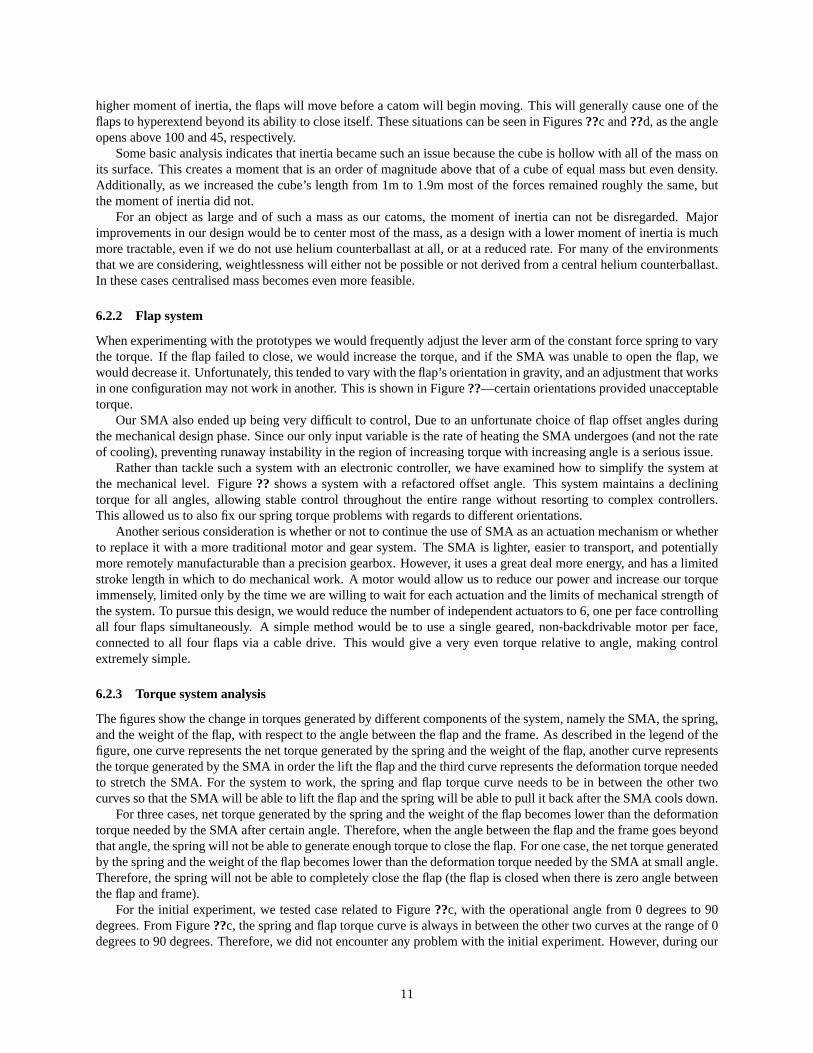
The electrodes come together forming couples that could be modeled as parallel plate capacitors shown in Fig-ure??a, where there is a coating of dielectric (mylar) on each electrode, and a certain amount of separation betweenelectrodes. The electrostatic force created in the case shown in Figure??a can be calculated as in equation??below:
F =Aε0V
2
(l + 2d/ε)2(2)
0.2 0.4 0.6 0.8 1 1.2 1.40
500
1000
1500
2000
2500
3000
3500
4000Weight lifted vs sidelength of Catom
Sidelength of Catom (m)
Wei
ght l
ifted
(N
)
seperation l = 20umseperation l = 50umseperation l = 100um
(a) (b)
Figure 6:a) Electrodes come together to form parallel plate capacitors b) The electrostatic force created wrt the catom side length.
The strength electrostatic forces created is the limiting factor for the amount of weight that could be lifted by acatom, without loosing contact with the neighbor catom. As the forces depend heavily on the area of electrodes, it isimportant to know how much weight could be lifted when the catoms are scaled down to different sizes. Figure??bshows the theoretical forces that would be created, with respect to different catom side lengths. The calculationassumes that the total area of a flap is one forth of the single face area of the catom.
The separation between electrodes plays an important role in the force created. Still, it is clear that the amount offorces created are well above the Catom weight range, thus electrostatic adhesion is promising for this application.
9
6 Experimental Verification of a Prototype Module
6.1 Actuation
6.1.1 Prototyping the mechanical system
Most of our early prototypes were developed using glue, balsa wood and plastic parts printed with a fused depositionmodeler. This allowed us to quickly test out designs as well as estimate the overall rigidity of the structure. Once wewere satisfied with the design, we adapted it to work with carbon fiber box beams. This gave us increased rigidity androbustness, as well as simplicity of assembly over complex balsa support structures.
Our flap actuation relied on a multipart system shown in Figure??. Our flaps attach rigidly to the frame using ahinge. Attached to the flap is a bundle of SMA which, when heated, contracts to pull the flap open. A continuous forcespring (similar to an ordinary tape measure), also attached between the frame and flap, provides the torque necessaryto stretch the SMA as it cools and return the flap back to its original position. It attaches to each using a zip-tiedfriction collar, both of which may be moved along the lengths of each beam to vary the amount of torque it generates.The original system was originally intended to open to 45 degrees, however, we found that in practice it could open toalmost 150, which increased the movements available to the cubes.
To construct the electrostatic plates, we wanted a material as light as possible that was electrically conductive onone side but isolated on the other. We chose aluminized Mylar, which has a high breakdown voltage and is available in2 and 4 micron thickness sheets. After testing both, we settled on the 4 micron sheet as it was easier to manipulate andwas less prone to damage during handling. Thicker materials were also available, but increasing the dielectric quicklyled to diminishing returns in electrostatic force.
To counteract the weight of the frame and flaps, each catom had a large internal balloon filled with helium. Thesewere constructed using a nylon sheet with a heat sealable plastic on one side and metal on the other. Multiple sheetswere placed on top of one another with the heat sealable sides facing each other, and by using a hot iron the edgeswere sealed. By using eight 4m long, 1m wide sheets of material, we were able to construct roughly square balloonswith sides approximately 1.9m long. When filled with helium it counteracts 5.6kg in earth gravity.
To assemble a catom, we first attached the uninflated balloon to the bare frame by taping it to the center of eachface. We then added approximately 800g of lead shot to the center of each face, to act as ballast and prevent theballoon from lifting the frame as it inflates. After the balloon was inflated, we added electronics and flap hardware,and reduced the ballast to compensate. Since we only attached four flaps to our two prototypes, the majority of theweight on the catom was ballast.
6.2 Problems encountered
During construction of the catoms, many details arose that had to be dealt with. While this is to be expected in anyproject, two categories of problems were serious enough to warrant considering significantly modifying the basicdesign.
6.2.1 Inertia
Our experiments revealed that inertia has a bigger factor than we had considered. Though our robots weigh under 50grams, the effective mass was closer to 6 kilograms with the center of mass almost 1 meter from the rotation point.Our initial hinge design was completely unable to cope with such torques and the catoms would twist and roll off axisdue to minute imbalances or wind currents. Adding additional hinges alleviated those problems, though our springreturn system still had to contend with ponderously slow payloads.
Additionally, the large amount of ballast also caused significant problems with structural stability as the balloondeflated over time. The frame was not designed to handle such weight, and the bottom face especially would tend tosag unless the balloon was inflated and supporting the ballast. Balancing the weight to prevent bias in rotation alsorequired a significant amount of time. We originally considered partially inflating the balloons for testing with fewerthan the full set of flaps, but the helium would pool at the top of the balloon, causing strange inertial problems as thecatoms rotated and the helium moved. By inflating the balloon completely the balloon would press out equally uponthe entire frame, equalizing the effect of the helium.
Inertia also had a larger effect on the movement of the flaps and cubes. We expected to be able to open the flaps,adhere them, and then allow the springs to return them to the closed position. However, since the catom has a much
10
higher moment of inertia, the flaps will move before a catom will begin moving. This will generally cause one of theflaps to hyperextend beyond its ability to close itself. These situations can be seen in Figures??c and??d, as the angleopens above 100 and 45, respectively.
Some basic analysis indicates that inertia became such an issue because the cube is hollow with all of the mass onits surface. This creates a moment that is an order of magnitude above that of a cube of equal mass but even density.Additionally, as we increased the cube’s length from 1m to 1.9m most of the forces remained roughly the same, butthe moment of inertia did not.
For an object as large and of such a mass as our catoms, the moment of inertia can not be disregarded. Majorimprovements in our design would be to center most of the mass, as a design with a lower moment of inertia is muchmore tractable, even if we do not use helium counterballast at all, or at a reduced rate. For many of the environmentsthat we are considering, weightlessness will either not be possible or not derived from a central helium counterballast.In these cases centralised mass becomes even more feasible.
6.2.2 Flap system
When experimenting with the prototypes we would frequently adjust the lever arm of the constant force spring to varythe torque. If the flap failed to close, we would increase the torque, and if the SMA was unable to open the flap, wewould decrease it. Unfortunately, this tended to vary with the flap’s orientation in gravity, and an adjustment that worksin one configuration may not work in another. This is shown in Figure??—certain orientations provided unacceptabletorque.
Our SMA also ended up being very difficult to control, Due to an unfortunate choice of flap offset angles duringthe mechanical design phase. Since our only input variable is the rate of heating the SMA undergoes (and not the rateof cooling), preventing runaway instability in the region of increasing torque with increasing angle is a serious issue.
Rather than tackle such a system with an electronic controller, we have examined how to simplify the system atthe mechanical level. Figure?? shows a system with a refactored offset angle. This system maintains a decliningtorque for all angles, allowing stable control throughout the entire range without resorting to complex controllers.This allowed us to also fix our spring torque problems with regards to different orientations.
Another serious consideration is whether or not to continue the use of SMA as an actuation mechanism or whetherto replace it with a more traditional motor and gear system. The SMA is lighter, easier to transport, and potentiallymore remotely manufacturable than a precision gearbox. However, it uses a great deal more energy, and has a limitedstroke length in which to do mechanical work. A motor would allow us to reduce our power and increase our torqueimmensely, limited only by the time we are willing to wait for each actuation and the limits of mechanical strength ofthe system. To pursue this design, we would reduce the number of independent actuators to 6, one per face controllingall four flaps simultaneously. A simple method would be to use a single geared, non-backdrivable motor per face,connected to all four flaps via a cable drive. This would give a very even torque relative to angle, making controlextremely simple.
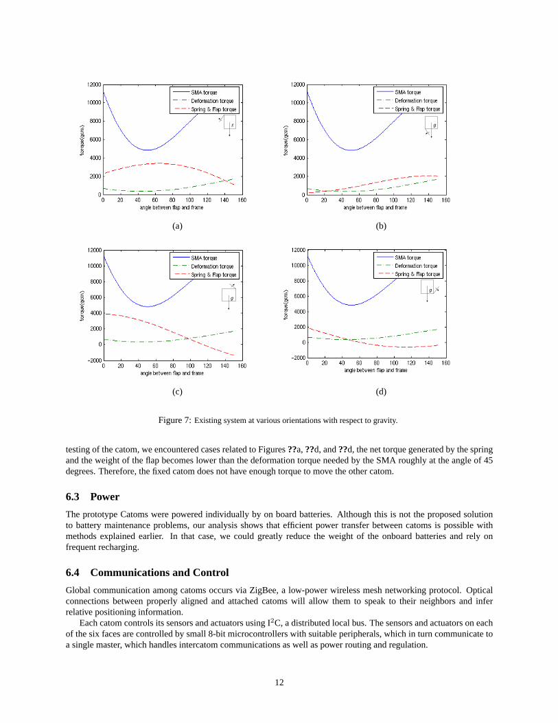
6.2.3 Torque system analysis
The figures show the change in torques generated by different components of the system, namely the SMA, the spring,and the weight of the flap, with respect to the angle between the flap and the frame. As described in the legend of thefigure, one curve represents the net torque generated by the spring and the weight of the flap, another curve representsthe torque generated by the SMA in order the lift the flap and the third curve represents the deformation torque neededto stretch the SMA. For the system to work, the spring and flap torque curve needs to be in between the other twocurves so that the SMA will be able to lift the flap and the spring will be able to pull it back after the SMA cools down.
For three cases, net torque generated by the spring and the weight of the flap becomes lower than the deformationtorque needed by the SMA after certain angle. Therefore, when the angle between the flap and the frame goes beyondthat angle, the spring will not be able to generate enough torque to close the flap. For one case, the net torque generatedby the spring and the weight of the flap becomes lower than the deformation torque needed by the SMA at small angle.Therefore, the spring will not be able to completely close the flap (the flap is closed when there is zero angle betweenthe flap and frame).
For the initial experiment, we tested case related to Figure??c, with the operational angle from 0 degrees to 90degrees. From Figure??c, the spring and flap torque curve is always in between the other two curves at the range of 0degrees to 90 degrees. Therefore, we did not encounter any problem with the initial experiment. However, during our
11
(a) (b)
(c) (d)
Figure 7:Existing system at various orientations with respect to gravity.
testing of the catom, we encountered cases related to Figures??a,??d, and??d, the net torque generated by the springand the weight of the flap becomes lower than the deformation torque needed by the SMA roughly at the angle of 45degrees. Therefore, the fixed catom does not have enough torque to move the other catom.
6.3 Power
The prototype Catoms were powered individually by on board batteries. Although this is not the proposed solutionto battery maintenance problems, our analysis shows that efficient power transfer between catoms is possible withmethods explained earlier. In that case, we could greatly reduce the weight of the onboard batteries and rely onfrequent recharging.
6.4 Communications and Control
Global communication among catoms occurs via ZigBee, a low-power wireless mesh networking protocol. Opticalconnections between properly aligned and attached catoms will allow them to speak to their neighbors and inferrelative positioning information.
Each catom controls its sensors and actuators using I2C, a distributed local bus. The sensors and actuators on eachof the six faces are controlled by small 8-bit microcontrollers with suitable peripherals, which in turn communicate toa single master, which handles intercatom communications as well as power routing and regulation.
12
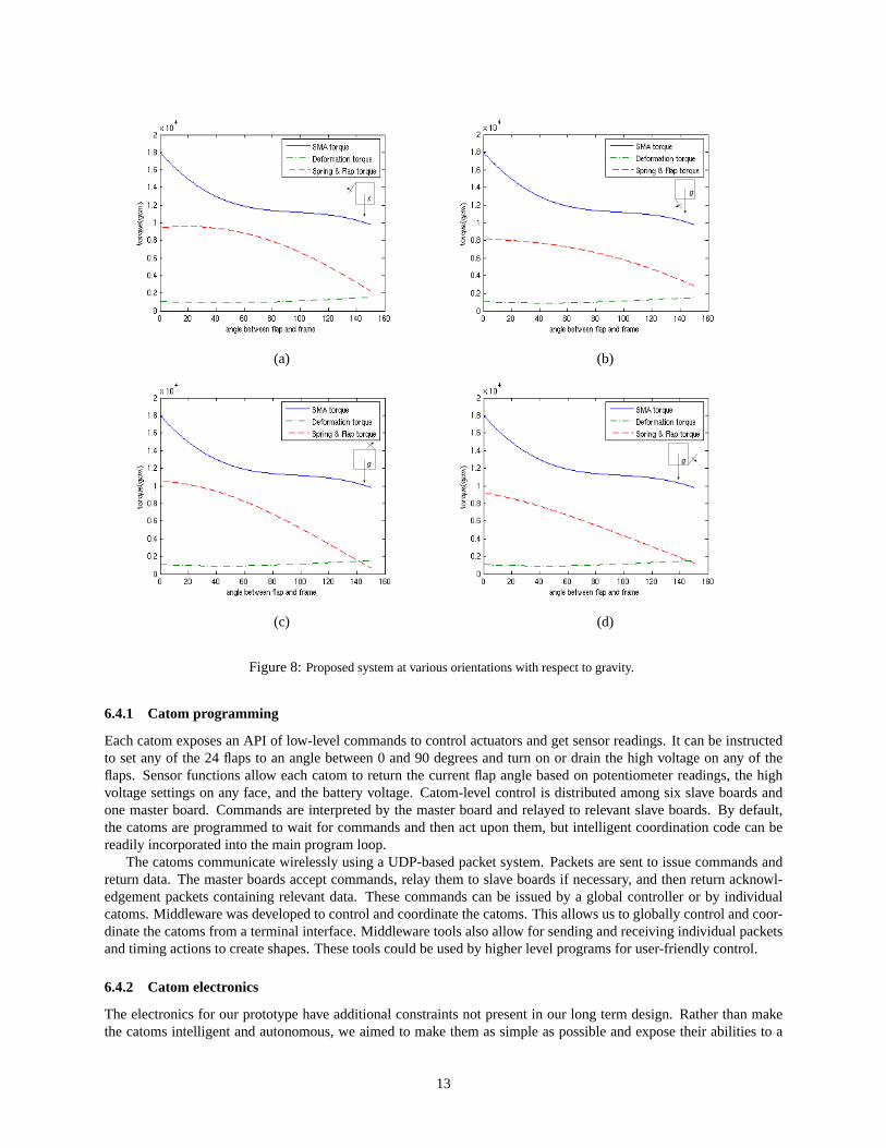
(a) (b)
(c) (d)
Figure 8:Proposed system at various orientations with respect to gravity.
6.4.1 Catom programming
Each catom exposes an API of low-level commands to control actuators and get sensor readings. It can be instructedto set any of the 24 flaps to an angle between 0 and 90 degrees and turn on or drain the high voltage on any of theflaps. Sensor functions allow each catom to return the current flap angle based on potentiometer readings, the highvoltage settings on any face, and the battery voltage. Catom-level control is distributed among six slave boards andone master board. Commands are interpreted by the master board and relayed to relevant slave boards. By default,the catoms are programmed to wait for commands and then act upon them, but intelligent coordination code can bereadily incorporated into the main program loop.
The catoms communicate wirelessly using a UDP-based packet system. Packets are sent to issue commands andreturn data. The master boards accept commands, relay them to slave boards if necessary, and then return acknowl-edgement packets containing relevant data. These commands can be issued by a global controller or by individualcatoms. Middleware was developed to control and coordinate the catoms. This allows us to globally control and coor-dinate the catoms from a terminal interface. Middleware tools also allow for sending and receiving individual packetsand timing actions to create shapes. These tools could be used by higher level programs for user-friendly control.
6.4.2 Catom electronics
The electronics for our prototype have additional constraints not present in our long term design. Rather than makethe catoms intelligent and autonomous, we aimed to make them as simple as possible and expose their abilities to a
13
host computer, so that we could quickly test a variety of different actuation strategies. Each prototype had its ownpower source, a pair of 18.4V lithium polymer batteries. Communications were handled using ZigBee, a low power,low bandwidth networking protocol which is great for coordinating a handful of modules but may not be tractable ona larger scale. Reprogramming the modules was done using a tether.
We chose to work with a distributed system. Though a single microcontroller is often easier to work with than adistributed system of multiple processors, we used multiple processors in order to reduce overall system weight andtake advantage of the peripherals of commercially available microcontrollers. Each robot is a cube almost two meterson a side, making light, low resistance wiring a challenge. Each flap requires several connections including two highcurrent wires for heating the SMA. Spreading the logic across several control boards allowed us to distribute the highcurrent power in a star pattern, reducing the necessary amount of wire. Additionally, since our system required aUART, 24 PWM outputs, 26 analog / digital conversion ports, and 48 digital outputs, there were no convenient com-mercial microcontrollers available that could handle our needs. Splitting the system up allowed us to take advantageof microcontroller peripherals, greatly simplifying the design.
We utilized ZigBee for intercatom communications. MaxStream’s XBee module allowed us to treat our wirelessnetwork as a multi-drop serial port, where all nodes receive the broadcasts of each other. Since each catom wasconfigured to only respond when a host computer sent it data, we did not have any problems with spurious traffic. Toscale in the future, each XBee module can be configured to only forward data packets to its host if the address matches.
For intracatom communication, we implemented I2C between the mother and daughter boards. To handle theless than ideal conditions of two meter cables, we used higher power buffered line drivers between boards. As flapcommands arrive at the motherboard via ZigBee, the mother forwards the requisite commands down to the relevantdaughter via I2C. Once the daughter has responded, the mother sends back a confirmation packet to the host computerwith an acknowledgement or the requested information. The mother can also broadcast emergency shutdown or haltconditions to all of her daughters at once.
To control flap angle, we implemented a proportional controller. It reads in a resistance corresponding to the angleof a potentiometer attached to our hinge and varies the power going to the SMA by changing the duty cycle of apulse-width modulated signal driving a power MOSFET. Higher power heats the SMA more, producing more torque,whereas lower or no power allows the SMA to cool off. While simple, this system was sufficient to test a variety ofcatom movements.
A serious problem with our prototype design was that our offset pulley design makes it difficult to control theangle. The SMA pulls about a diameter that is offset from the center of rotation, which means that the torque willvary with angle. Additionally, the SMA tends to decline in strength as it contracts, and behavior as evidenced inFigure?? occurs. For angles below 45 degrees, the torque steadily decreases as the angle increases, which minimizesthe overshoot and oscillations common in a proportional controller. However, as soon as the angle crosses 45 degress,the torque increases and the system overshoots to its mechanical stop. The only way to counter this effect would be tocarefully cool the SMA at a proper rate, something very dependent on environment temperature and convection. Thebetter solution was instead to modify the mechanical system to remove this behavior, as seen in Figure??.
6.5 Adhesion
Our adhesion relies upon strong electrostatic forces generated between flaps. We noticed a major difference betweenthe theorized and the observed experimental results, mainly between the measured electrostatic forces and the theoret-ically calculated forces. The difference is a few orders of magnitude, where the measured forces are much lower.
There are several factors that are to be considered. One is that the prototypes had electrodes composed of floppyconductors coated with a dielectric material. Although a good seal was established when electrodes were excited, thefact that the conducting surfaces were flexible caused the amount of force necessary to separate them to decrease. Thiscan be explained with peeling effect, where the two electrodes are easily pealed off at the boundary of the contact. Thering of surface that surrounds the boundary can move independently of the contact, so very small forces can actuallypropagate peeling into the boundary, eventually causing the entire surface to snap off. This could be avoided usingrigid electrodes, where peeling would not happen.
Another factor is that there is no easy way to estimate the amount of separation between electrodes. A sub-millimeter separation is virtually impossible to see by eye, so the assumptions on the separation might not hold.Our experiments show that there is always a certain amount of separation caused by non-uniformities or wrinkles inmaterial, though we have yet to devise an experiment that will allow us to accurately measure these gaps.
14

7 Conclusion
We have described a lightweight construction system to allow the rapid and autonomous deployment of orbital andplanetary facilities on the moon and Mars. The construction system is composed of an ensemble of modular robots,called catoms. We designed, constructed, and tested a prototype system composed of two catoms which validated thebasic principles underlying out design.
Acknowledgements
This work could not have been done without the amazing and excellent advise, help, and labor of the many people inthe Claytronics group. In particular we would like to thank Burak Aksak, Jason Campbell, Babu Pillai, Nels Beckman,Byung Woo Yoon, and Todd Mowry. This work was supported in part by DARPA, NSF, CMU, and Intel Corporation.
15