Embed Size (px)
Citation preview
behringer.com
User Manual
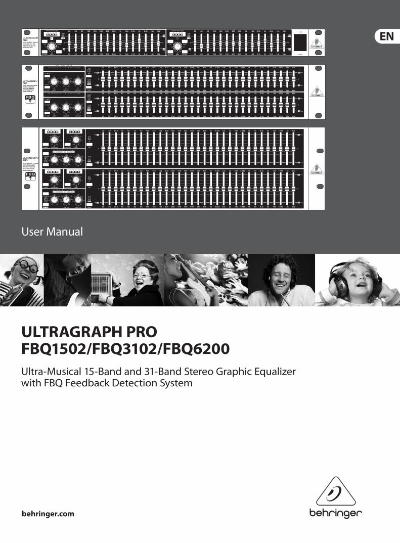
ULTRAGRAPH PRO FBQ1502/FBQ3102/FBQ6200Ultra-Musical 15-Band and 31-Band Stereo Graphic Equalizer with FBQ Feedback Detection System
behringer.com
2 ULTRAGRAPH PRO FBQ1502/FBQ3102/FBQ6200 User Manual
Thank youThank you very much for ex pressing your con fi dence in our products by purchasing one of our equalizers. This 2-channel high-end equalizer was designed with our experience and know-how in filter technology spanning many years. Our analog and digital equalizers are used the world over in various reputable studios, P.A. systems and radio and TV stations. Just like with the rest of our product line, when we started designing the new ULTRAGRAPH PRO models, we had put forth uncompromizing demands in terms of controls, sound, technical data and fit-and-finish quality.
Table of ContentsThank you ....................................................................... 2Important Safety Instructions ...................................... 3Legal Disclaimer ............................................................. 3Limited Warranty ........................................................... 31. Introduction ............................................................... 5
1.1 Before you get started ...................................................... 5
1.1.1 Shipment .......................................................................... 5
1.1.2 Initial operation ............................................................. 5
1.1.3 Warranty ........................................................................... 5
1.2 The user’s manual ............................................................... 5
2. Control Elements and Connectors ........................... 62.1 Front panel ............................................................................ 6
2.2 Rear panel ............................................................................. 6
2.3 Additional FBQ6200 control elements ...................... 7
2.3.1 Limiter .............................................................................. 7
2.3.2 Noise generator ............................................................ 8
2.3.3 Subwoofer section ....................................................... 8
3. Application Examples ............................................... 83.1 Master equalizer in sound reinforcement systems ............................................................ 9
3.2 Equalizer in the monitor path ........................................ 9
3.2.1 Priming a monitor system ....................................... 10
3.3 Using the ULTRAGRAPH PRO in the studio ............. 10
3.4 Special sound effects ...................................................... 10
4. Installation ............................................................... 104.1 Rack mounting .................................................................. 10
4.2 Audio connections ........................................................... 10
5. Specifications ........................................................... 12
3 ULTRAGRAPH PRO FBQ1502/FBQ3102/FBQ6200 User Manual
behringer.com
Terminals marked with this symbol carry electrical current of suffi cient magnitude to constitute risk of electric shock. Use only
high-quality commercially-available speaker cables with ¼" TS plugs pre-installed. All other installation or modifi cation should be performed only by qualifi ed personnel.
This symbol, wherever it appears, alerts you to the presence of uninsulated dangerous voltage inside the enclosure - voltage that
may be suffi cient to constitute a risk of shock.
This symbol, wherever it appears, alerts you to important operating and maintenance instructions in the accompanying literature.
Please read the manual.
CautionTo reduce the risk of electric shock, do not remove the top cover (or the rear section).
No user serviceable parts inside. Refer servicing to qualifi ed personnel.
CautionTo reduce the risk of fi re or electric shock, do not expose this appliance to rain and
moisture. The apparatus shall not be exposed to dripping or splashing liquids and no objects fi lled with liquids, such as vases, shall be placed on the apparatus.
CautionThese service instructions are for use by qualifi ed service personnel only.
To reduce the risk of electric shock do not perform any servicing other than that contained in the operation instructions. Repairs have to be performed by qualifi ed service personnel.
Read these instructions.1.
Keep these instructions.2.
Heed all warnings.3.
Follow all instructions.4.
Do not use this apparatus near water.5.
Clean only with dry cloth.6.
Do not block any ventilation openings. Install in 7. accordance with the manufacturer’s instructions.
Do not install near any heat sources such as 8. radiators, heat registers, stoves, or other apparatus (including amplifi ers) that produce heat.
Do not defeat the safety purpose of the polarized 9. or grounding-type plug. A polarized plug has two blades with one wider than the other. A grounding-type plug has two blades and a third grounding prong. The wide blade or the third prong are provided for your safety. If the provided plug does not fi t into your outlet, consult an electrician for replacement of the obsolete outlet.
Protect the power cord from being walked on or 10. pinched particularly at plugs, convenience receptacles, and the point where they exit from the apparatus.
Use only attachments/accessories specifi ed by 11. the manufacturer.
Use only with the 12. cart, stand, tripod, bracket, or table specifi ed by the manufacturer, or sold with the apparatus. When a cart is used, use caution when moving the cart/apparatus combination to avoid
injury from tip-over.
Unplug this apparatus during lightning storms or 13. when unused for long periods of time.
Refer all servicing to qualifi ed service personnel. 14. Servicing is required when the apparatus has been damaged in any way, such as power supply cord or plug is damaged, liquid has been spilled or objects have fallen into the apparatus, the apparatus has been exposed to rain or moisture, does not operate normally, or has been dropped.
The apparatus shall be connected to a MAINS socket 15. outlet with a protective earthing connection.
Where the MAINS plug or an appliance coupler is 16. used as the disconnect device, the disconnect device shall remain readily operable.
Technical specifi cations and appearance are subject to change without notice. The information contained herein is correct at the time of printing. All trademarks are the property of their respective owners. MUSIC Group accepts no liability for any loss which may be suff ered by any person who relies either wholly or in part upon any description, photograph or statement contained herein. Colors and specifi cations may vary slightly from product. BEHRINGER products are sold through authorized dealers only. Distributors and dealers are not agents of MUSIC Group and have absolutely no authority to bind MUSIC Group by any express or implied undertaking or representation. This manual is copyrighted. No part of this manual may be reproduced or transmitted in any form or by any means, electronic or mechanical, including photocopying and recording of any kind, for any purpose, without the express written permission of Red Chip Company Ltd.
ALL RIGHTS RESERVED. © 2010 Red Chip Company Ltd. Trident Chambers, Wickhams Cay, P.O. Box 146,Road Town, Tortola, British Virgin Islands
Warranty§ 1 This limited warranty is valid only if you purchased [1]
the product from a BEHRINGER authorized dealer in the country of purchase. A list of authorized dealers can be found on BEHRINGER’s website behringer. com under “Where to Buy“, or you can contact the BEHRINGER offi ce closest to you.
MUSIC Group* warrants the mechanical and [2]
electronic components of this product to be free of defects in material and workmanship if used under normal operating conditions for a period of one (1) year from the original date of purchase (see the Limited Warranty terms in § 4 below), unless a longer minimum warranty period is mandated by applicable local laws. If the product shows any defects within the specifi ed warranty period and that defect is not excluded under § 4, MUSIC Group shall, at its discretion, either replace or repair the product using suitable new or reconditioned product or parts. In case MUSIC Group decides to replace the entire product, this limited warranty shall apply to the replacement product for the remaining initial warranty period, i.e., one (1) year (or otherwise applicable minimum warranty period) from the date of purchase of the original product.
Upon validation of the warranty claim, the repaired [3]
or replacement product will be returned to the user freight prepaid by MUSIC Group.
Warranty claims other than those indicated above [4]
are expressly excluded.
PLEASE RETAIN YOUR SALES RECEIPT. IT IS YOUR PROOF OF PURCHASE COVERING YOUR LIMITED WARRANTY. THIS LIMITED WARRANTY IS VOID WITHOUT SUCH PROOF OF PURCHASE.
Online registration§ 2 Please do remember to register your new BEHRINGER equipment right after your purchase at behringer. com under “Support” and kindly read the terms and conditions of our limited warranty carefully. Registering your purchase and equipment with us helps us process your repair claims quicker and more effi ciently. Thank you for your cooperation!
Return materials authorization§ 3 To obtain warranty service, please contact the [1]
retailer from whom the equipment was purchased. Should your BEHRINGER dealer not be located in your vicinity, you may contact the BEHRINGER distributor for your country listed under “Support” at behringer. com. If your country is not listed, please check if your problem can be dealt with by our “Online Support” which may also be found under “Support” at behringer. com. Alternatively, please submit an online warranty claim at behringer. com BEFORE returning the product. All inquiries must be accompanied by a description of the problem and the serial number of the product. After verifying the product’s warranty eligibility with the original sales receipt, MUSIC Group will then issue a Return Materials Authorization (“RMA”) number.
Legal Disclaimer
Limited WarrantyImportant Safety Instructions
Important Safety Instructions
Legal Disclaimer
Limited Warranty
behringer.com
4 ULTRAGRAPH PRO FBQ1502/FBQ3102/FBQ6200 User Manual
Subsequently, the product must be returned in [2]
its original shipping carton, together with the return authorization number to the address indicated by MUSIC Group.
Shipments without freight prepaid will not [3]
be accepted.
Warranty Exclusions§ 4 This limited warranty does not cover consumable [1]
parts including, but not limited to, fuses and batteries. Where applicable, MUSIC Group warrants the valves or meters contained in the product to be free from defects in material and workmanship for a period of ninety (90) days from date of purchase.
This limited warranty does not cover the product [2]
if it has been electronically or mechanically modifi ed in any way. If the product needs to be modifi ed or adapted in order to comply with applicable technical or safety standards on a national or local level, in any country which is not the country for which the product was originally developed and manufactured, this modifi cation/adaptation shall not be considered a defect in materials or workmanship. This limited warranty does not cover any such modifi cation/adaptation, regardless of whether it was carried out properly or not. Under the terms of this limited warranty, MUSIC Group shall not be held responsible for any cost resulting from such a modifi cation/adaptation.
This limited warranty covers only the product [3]
hardware. It does not cover technical assistance for hardware or software usage and it does not cover any software products whether or not contained in the product. Any such software is provided “AS IS” unless expressly provided for in any enclosed software limited warranty.
This limited warranty is invalid if the factory-[4]
applied serial number has been altered or removed from the product.
Free inspections and maintenance/repair work [5]
are expressly excluded from this limited warranty, in particular, if caused by improper handling of the product by the user. This also applies to defects caused by normal wear and tear, in particular, of faders, crossfaders, potentiometers, keys/buttons, guitar strings, illuminants and similar parts.
Damage/defects caused by the following conditions [6]
are not covered by this limited warranty:
improper handling, neglect or failure to operate the •unit in compliance with the instructions given in BEHRINGER user or service manuals;
connection or operation of the unit in any way •that does not comply with the technical or safety regulations applicable in the country where the product is used;
damage/defects caused by acts of God/Nature •(accident, fi re, fl ood, etc) or any other condition that is beyond the control of MUSIC Group.
Any repair or opening of the unit carried out by [7]
unauthorized personnel (user included) will void the limited warranty.
If an inspection of the product by MUSIC Group [8]
shows that the defect in question is not covered by the limited warranty, the inspection costs are payable by the customer.
Products which do not meet the terms of this [9]
limited warranty will be repaired exclusively at the buyer’s expense. MUSIC Group or its authorized service center will inform the buyer of any such circumstance. If the buyer fails to submit a written repair order within 6 weeks after notifi cation, MUSIC Group will return the unit C.O.D. with a separate invoice for freight and packing. Such costs will also be invoiced separately when the buyer has sent in a written repair order.
Authorized BEHRINGER dealers do not sell new [10]
products directly in online auctions. Purchases made through an online auction are on a “buyer beware” basis. Online auction confi rmations or sales receipts are not accepted for warranty verifi cation and MUSIC Group will not repair or replace any product purchased through an online auction.
Warranty transferability§ 5 This limited warranty is extended exclusively to the original buyer (customer of authorized retail dealer) and is not transferable to anyone who may subsequently purchase this product. No other person (retail dealer, etc.) shall be entitled to give any warranty promise on behalf of MUSIC Group.
Claim for damage§ 6 Subject only to the operation of mandatory applicable local laws, MUSIC Group shall have no liability to the buyer under this warranty for any consequential or indirect loss or damage of any kind. In no event shall the liability of MUSIC Group under this limited warranty exceed the invoiced value of the product.
Limitation of liability§ 7 This limited warranty is the complete and exclusive warranty between you and MUSIC Group. It supersedes all other written or oral communications related to this product. MUSIC Group provides no other warranties for this product.
Other warranty rights and § 8 national law
This limited warranty does not exclude or limit the [1]
buyer’s statutory rights as a consumer in any way.
The limited warranty regulations mentioned herein [2]
are applicable unless they constitute an infringement of applicable mandatory local laws.
This warranty does not detract from the seller’s [3]
obligations in regard to any lack of conformity of the product and any hidden defect.
Amendment§ 9 Warranty service conditions are subject to change without notice. For the latest warranty terms and conditions and additional information regarding MUSIC Group’s limited warranty, please see complete details online at behringer. com.
* MUSIC Group Macao Commercial Off shore Limited of
Rue de Pequim No. 202-A, Macau Finance Centre 9/J, Macau,
including all MUSIC Group companies
5 ULTRAGRAPH PRO FBQ1502/FBQ3102/FBQ6200 User Manual
behringer.com
Introduction1. FBQ Feedback Detection System
The FBQ Feedback Detection System is one of the most outstanding characteristcs of our graphic equalizers. This ingenious circuitry lets you immediately recognize and eliminate feedback frequencies. The FBQ Feedback Detection System uses the LEDs in the frequency band faders to indicate the critical frequencies. This way, what once used to be a labor-intensive search for feedback frequencies is now an activity that even a child could master.
In normal operation, the fader LEDs indicate frequency ranges with the highest energy levels, therefore replacing a separate audio analyzer. If you keep an eye on the LEDs while you play back your music (or during the sound check before a show), you can easily identify those frequency ranges showing the highest energy levels. Similarly, increased signal levels on individual frequency bands indicate a higher likelihood that feedback may occur.
All three models feature a dedicated subwoofer output with adjustable cut-off frequency. You can also adjust the fader range from ±6 to ±12 dB for each channel independently.
The FBQ1502 requires just one rack space, yet it offers you tons of effective methods for adjusting the sound characteristics, and is ultra-compact and extremely simple to operate.
The FBQ3102 features 31 frequency bands per channel as well as adjustable high-pass and low-pass filters. These filters further augment the adjustability options available to you.
With its integrated limiters, noise generator and the adjustable subwoofer output with signal level display and its 62 lighted 45 mm faders, the FBQ6200 is our top model in this category.
Future-oriented BEHRINGER technology
To assure the highest possible degree of usability, all our equipment is manufactured adhering to the highest quality standards in the audio industry. Your equalizer has been manufactured under ISO9000 certified management system.
Relay-controlled hard bypass
The so-called hard bypass relays were integrated into the development concept of the FBQ6200 and the FBQ3102. These relays assure that your equalizer is automatically switched into bypass mode in the event of loss of power or faulty power delivery. These fail-safe relays also produce a slight delay during powering up in order to avoid dangerous switch-on thumps.
Balanced inputs and outputs
The BEHRINGER ULTRAGRAPH PRO models feature electronic servo-balanced inputs and outputs. The servo function performs automatically, recognizing when unbalanced signals are connected and internally converts the nominal signal level so that no signal level difference between input and output signals occurs (6 dB correction).
The following user’s manual is intended to familiarize you with the ◊ unit’s control elements, so that you can master all the functions. After having thoroughly read the user’s manual, store it at a safe place for future reference.
Before you get started1.1
Shipment1.1.1
The ULTRAGRAPH PRO was carefully packed at the factory to assure secure transport. Should the condition of the cardboard box suggest that damage may have taken place, please inspect the unit immediately and look for physical indications of damage.
Damaged units should NEVER be sent directly to us. Please inform the ◊ dealer from whom you acquired the unit immediately as well as the transportation company from which you took delivery of the unit. Otherwise, all claims for replacement/repair may be rendered invalid.
Initial operation1.1.2
Please make sure the unit is provided with sufficient ventilation, and never place the ULTRAGRAPH PRO on top of an amplifier or in the vicinity of a heater to avoid the risk of overheating.
Before plugging the unit into a power socket, please make sure you ◊ have selected the correct voltage:
The fuse compartment near the power plug socket contains three triangular markings. Two of these triangles are opposite one another. The voltage indicated adjacent to these markings is the voltage to which your unit has been set up, and can be altered by rotating the fuse compartment by 180°. ATTENTION: This does not apply to export models that were for example manufactured only for use with 120 V!
If you alter the unit’s voltage, you must change the fuse accordingly. ◊ The correct value of the fuse needed can be found in the chapter “Specifications”.
Faulty fuses must be replaced with fuses of appropriate rating without ◊ exception! The correct value of the fuse needed can be found in the chapter “Specifications”.
Power is delivered via the cable provided with the unit. All requiered safety precautions have been adhered to.
Please make sure that the unit is grounded at all times. For your own ◊ protection, you should never tamper with the grounding of the cable or the unit itself.
Warranty1.1.3
Please take a few minutes and send us the completely filled out warranty card within 14 days of the date of purchase. You may also register online at behringer.com. The serial number needed for the registration is located on the rear of the unit. Failure to register your product may void future warranty claims.
The user’s manual1.2 The user’s manual is designed to give you both an overview of the control elements, as well as detailed information on how to use them. In order to help you understand the links between the controls, we have arranged them in groups according to their function. Should you need detailed information about specific topics not covered in this manual, please visit our website at behringer.com. For example, additional information about power amps and effects processors is found there.
behringer.com
6 ULTRAGRAPH PRO FBQ1502/FBQ3102/FBQ6200 User Manual
Control Elements and Connectors2. Front panel2.1
In this chapter we will describe various control elements of your equalizer. All controls and connectors are explained in detail, and you will also find useful hints on how to best use them. Since the three equalizers in the FBQ series are fairly similar, let’s start with the control elements of the FBQ1502 and the FBQ3102 that are similar to the control elements found on the FBQ6200. The FBQ6200 additionally features extra control elements that will be explained in detail later on.
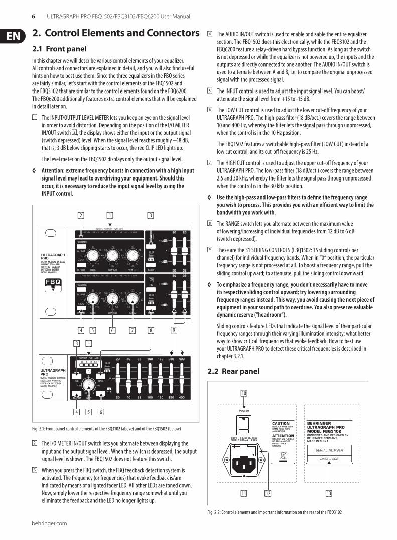
The INPUT/OUTPUT LEVEL METER lets you keep an eye on the signal level [1]in order to avoid distortion. Depending on the position of the I/O METER IN/OUT switch [2], the display shows either the input or the output signal (switch depressed) level. When the signal level reaches roughly +18 dB, that is, 3 dB below clipping starts to occur, the red CLIP LED lights up.
The level meter on the FBQ1502 displays only the output signal level.
Attention: extreme frequency boosts in connec tion with a high input ◊ signal level may lead to over driving your equipment. Should this occur, it is necessary to reduce the input signal level by using the INPUT control.
[4] [5]
[3]
[4]
[2] [1] [3]
[5] [6] [7]
[1]
[6]
[8] [9]
Fig. 2.1: Front panel control elements of the FBQ3102 (above) and of the FBQ1502 (below)
The I/O METER IN/OUT switch lets you alternate between displaying the [2]input and the output signal level. When the switch is depressed, the output signal level is shown. The FBQ1502 does not feature this switch.
When you press the FBQ switch, the FBQ feedback detection system is [3]activated. The frequency (or frequen cies) that evoke feedback is/are indicated by means of a lighted fader LED. All other LEDs are toned down. Now, simply lower the respective frequency range somewhat until you eliminate the feedback and the LED no longer lights up.
The AUDIO IN/OUT switch is used to enable or disable the entire equalizer [4]section. The FBQ1502 does this electronically, while the FBQ3102 and the FBQ6200 feature a relay-driven hard bypass function. As long as the switch is not depressed or while the equalizer is not powered up, the inputs and the outputs are directly connected to one another. The AUDIO IN/OUT switch is used to alternate between A and B, i.e. to compare the original unprocessed signal with the processed signal.
The INPUT control is used to adjust the input signal level. You can boost/[5]attenuate the signal level from +15 to -15 dB.
The LOW CUT control is used to adjust the lower cut-off frequency of your [6]ULTRAGRAPH PRO. The high-pass filter (18 dB/oct.) covers the range between 10 and 400 Hz, whereby the filter lets the signal pass through unprocessed, when the control is in the 10 Hz position.
The FBQ1502 features a switchable high-pass filter (LOW CUT) instead of a low cut control, and its cut-off frequency is 25 Hz.
The HIGH CUT control is used to adjust the upper cut-off frequency of your [7]ULTRAGRAPH PRO. The low-pass filter (18 dB/oct.) covers the range between 2.5 and 30 kHz, whereby the filter lets the signal pass through unprocessed when the control is in the 30 kHz position.
Use the high-pass and low-pass filters to define the frequency range ◊ you wish to process. This provides you with an efficient way to limit the bandwidth you work with.
The RANGE switch lets you alternate between the maximum value [8]of lowering/increasing of individual frequencies from 12 dB to 6 dB (switch depressed).
These are the 31 SLIDING CONTROLS (FBQ1502: 15 sliding controls per [9]channel) for individual frequency bands. When in “0” position, the particular frequency range is not processed at all. To boost a frequency range, pull the sliding control upward; to attenuate, pull the sliding control downward.
To emphasize a frequency range, you don’t necessarily have to move ◊ its respective sliding control upward; try lowering surrounding frequency ranges instead. This way, you avoid causing the next piece of equipment in your sound path to overdrive. You also preserve valuable dynamic reserve (“headroom”).
Sliding controls feature LEDs that indicate the signal level of their particular frequency ranges through their varying illumination intensity: what better way to show critical frequencies that evoke feedback. How to best use your ULTRAGRAPH PRO to detect these critical frequencies is described in chapter 3.2.1.
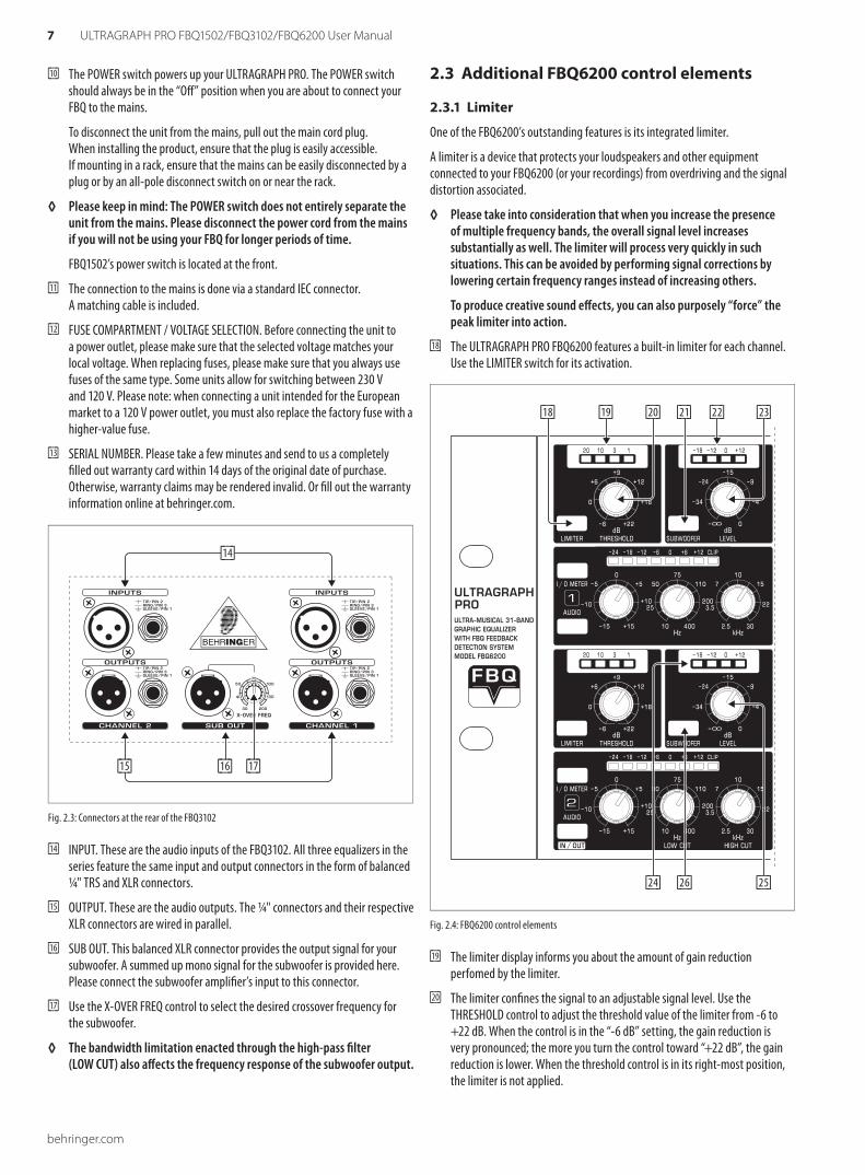
Rear panel2.2
[10]
[11] [12] [13]
Fig. 2.2: Control elements and important information on the rear of the FBQ3102
7 ULTRAGRAPH PRO FBQ1502/FBQ3102/FBQ6200 User Manual
behringer.com
The POWER switch powers up your ULTRAGRAPH PRO. The POWER switch [10]should always be in the “Off” position when you are about to connect your FBQ to the mains.
To disconnect the unit from the mains, pull out the main cord plug. When installing the product, ensure that the plug is easily accessible. If mounting in a rack, ensure that the mains can be easily disconnected by a plug or by an all-pole disconnect switch on or near the rack.
Please keep in mind: The POWER switch does not entirely separate the ◊ unit from the mains. Please disconnect the power cord from the mains if you will not be using your FBQ for longer periods of time.
FBQ1502’s power switch is located at the front.
The connection to the mains is done via a standard IEC connector. [11]A matching cable is included.
FUSE COMPARTMENT / VOLTAGE SELECTION. Before connecting the unit to [12]a power outlet, please make sure that the selected voltage matches your local voltage. When replacing fuses, please make sure that you always use fuses of the same type. Some units allow for switching between 230 V and 120 V. Please note: when connecting a unit intended for the European market to a 120 V power outlet, you must also replace the factory fuse with a higher-value fuse.
SERIAL NUMBER. Please take a few minutes and send to us a completely [13]filled out warranty card within 14 days of the original date of purchase. Otherwise, warranty claims may be rendered invalid. Or fill out the warranty information online at behringer.com.
[14]
[16][15] [17]
Fig. 2.3: Connectors at the rear of the FBQ3102
INPUT. These are the audio inputs of the FBQ3102. All three equalizers in the [14]series feature the same input and output connectors in the form of balanced ¼" TRS and XLR connectors.
OUTPUT. These are the audio outputs. The ¼" connectors and their respective [15]XLR connectors are wired in parallel.
SUB OUT. This balanced XLR connector provides the output signal for your [16]subwoofer. A summed up mono signal for the subwoofer is provided here. Please connect the subwoofer amplifier’s input to this connector.
Use the X-OVER FREQ control to select the desired crossover frequency for [17]the subwoofer.
The bandwidth limitation enacted through the high-pass filter ◊ (LOW CUT) also affects the frequency response of the subwoofer output.
Additional FBQ6200 control elements 2.3
Limiter 2.3.1
One of the FBQ6200’s outstanding features is its integrated limiter.
A limiter is a device that protects your loudspeakers and other equipment connected to your FBQ6200 (or your recordings) from overdriving and the signal distortion associated.
Please take into consideration that when you increase the presence ◊ of multiple frequency bands, the overall signal level increases subs tantially as well. The limiter will process very quickly in such situations. This can be avoided by performing signal corrections by lowering certain frequency ranges instead of increasing others.
To produce creative sound effects, you can also purposely “force” the peak limiter into action.
The ULTRAGRAPH PRO FBQ6200 features a built-in limiter for each channel. [18]Use the LIMITER switch for its activation.
[18] [19] [20] [21] [22] [23]
[24] [26] [25]
Fig. 2.4: FBQ6200 control elements
The limiter display informs you about the amount of gain reduction [19]perfomed by the limiter.
The limiter confines the signal to an adjustable signal level. Use the [20]THRESHOLD control to adjust the threshold value of the limiter from -6 to +22 dB. When the control is in the “-6 dB” setting, the gain reduction is very pronounced; the more you turn the control toward “+22 dB”, the gain reduction is lower. When the threshold control is in its right-most position, the limiter is not applied.
behringer.com
8 ULTRAGRAPH PRO FBQ1502/FBQ3102/FBQ6200 User Manual
Noise generator2.3.2
By using the built-in noise generator, you can create the so-called “pink noise” that can be used to adjust your P.A. system to specific acoustic characteristics of various venues.
Activate the pink noise generator by using the PINK NOISE switch. [21]The built-in switch illumination blinks red when the pink noise generator is activated.
Read off the noise generator’s signal level on the LED display.[22]
Use the NOISE LEVEL control to adjust the volume of the pink noise [23]you generate.
Room resonance and sound transfer characteristics of the P.A. system cause some frequencies to be more prominently present while other frequencies are less present. Pink noise is a neutral signal that can be played back via the P.A. system in order to measure these sound characteristics.
Such a measurement of the frequency response by using a special microphone in conjunction with a real-time analyzer (a real-time analyzer is for example integrated into the BEHRINGER ULTRACURVE PRO DEQ2496) delivers the basis for setting up the equalizer. More pronounced frequencies are lowered, and those frequencies that are not so prominently featured are increased, thus approximately achieving linear reproduction.
Try to orient yourself on a frequency whose signal level lies in the 0 dB ◊ to -3 dB range in order to avoid overdriving the equipment connected (e.g. power amplifier, crossover).
Subwoofer section2.3.3
The LED display indicates the signal level present at the SUB OUT connector.[24]
The signal level present at the subwoofer output connector can be adjusted [25]by using the LEVEL control.
To activate the subwoofer output, please depress the SUBWOOFER switch.[26]
In general, the location of a subwoofer is not critical, since the source of deeper freqencies is not easily determined. However, to achieve optimal sound resolution, you should try to position the subwoofer in a central location between the two main speakers. This way, you minimize run-time differences and the sound quality deterioration associated with them.
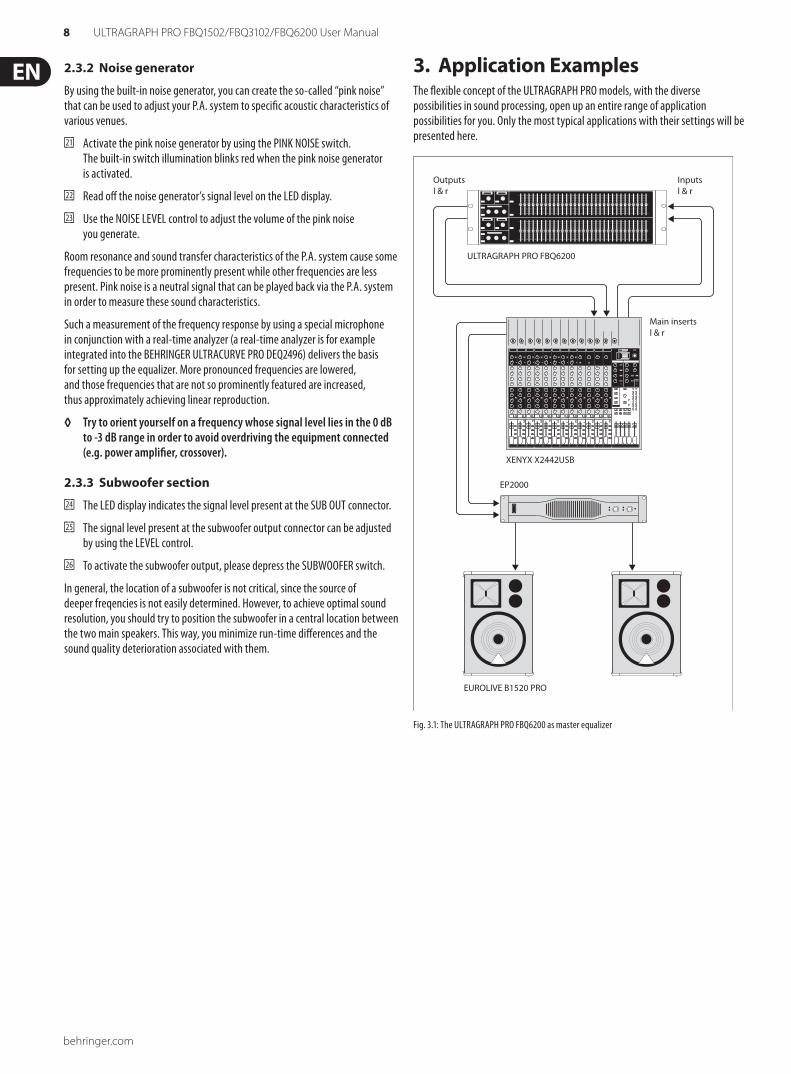
Application Examples3. The flexible concept of the ULTRAGRAPH PRO models, with the diverse possibilities in sound processing, open up an entire range of application possibilities for you. Only the most typical applications with their settings will be presented here.
XENYX X2442USB
ULTRAGRAPH PRO FBQ6200
Main insertsl & r
Inputsl & r
Outputsl & r
EP2000
EUROLIVE B1520 PRO
Fig. 3.1: The ULTRAGRAPH PRO FBQ6200 as master equalizer
9 ULTRAGRAPH PRO FBQ1502/FBQ3102/FBQ6200 User Manual
behringer.com
Master equalizer in sound 3.1 reinforcement systems This diagram shows a typical set-up with the ULTRAGRAPH PRO models (see fig. 3.1).
To achieve optimal results, you should pay attention to several issues:
Before you start correcting the frequency response of a setup, it is advisable to first let the music and other sound sources run “uncorrected”, as this is something that has proven itself in practice. If distortion occurs, such overdriving is the first issue to be overcome in your setup. Loudspeaker location is also very important. No equalizer in this world can significantly correct the dull sound created through reflexion of wall structures and ceilings. Often, very dramatic improvements can be made by simply placing and aligning speakers correctly.
If you are using an active multi-way system you should take some run-time and phase correction measures before you work with the ULTRAGRAPH PRO (our crossover network SUPER-X PRO CX3400 provides all the necessary tools with its variable split frequencies, phase reverse switches and electronic run-time correction facility). Only after making these preliminary adjustments should you start implementing them on your ULTRAGRAPH PRO.
Disturbing noise (e. g. mains-induced hum) as well as narrow-band resonances should first be tackled by using the ULTRAGRAPH PRO (also see ch. 3.2.1). You should definitely perform all these adjustments before modifying the overall sound.
Now you have a basic setup and now it’s time to start fine-tuning your sound.
Some ground rules:
A linear response curve is not ideal for every application. For example, when dealing with the spoken word, intelligibility is what is most important. Therefore, the transmission curve should drop off in the bass segment of the signal because otherwise only interference is transmitted.
In general, extremely low and high frequencies are transmitted with much lower amplitudes. There is no sense in “forcing” a small full-range speaker to reproduce frequencies below 50 Hz; apart from a need for higher power reserves, speaker damage will be the most likely result.
Always respect the physical limitations of your system.◊
After setting up your system as precisely as possible to the desired transmission curve, walk around the venue in order to get an impression of what your signal sounds like in different locations. Do not forget to take regular breaks while you do this, and also try to use various program sources to truly develop a feeling for what your system really sounds like and how the venue carries the sound.
Setting up your equalizer well takes a lot of time and patience! If you ◊ notice that only extreme settings on your equalizer create a usable frequency response, this is probably a good indication that a cardinal mistake may have been committed elsewhere in the P.A. system or room acoustics.
An equalizer is no solution for bad equipment, but it is an extremely useful and effective sound tool for musical fine-tuning. Fine-tuning often leads to amazing improvements in acoustic penetration and in the overall sound quality of your entire setup.
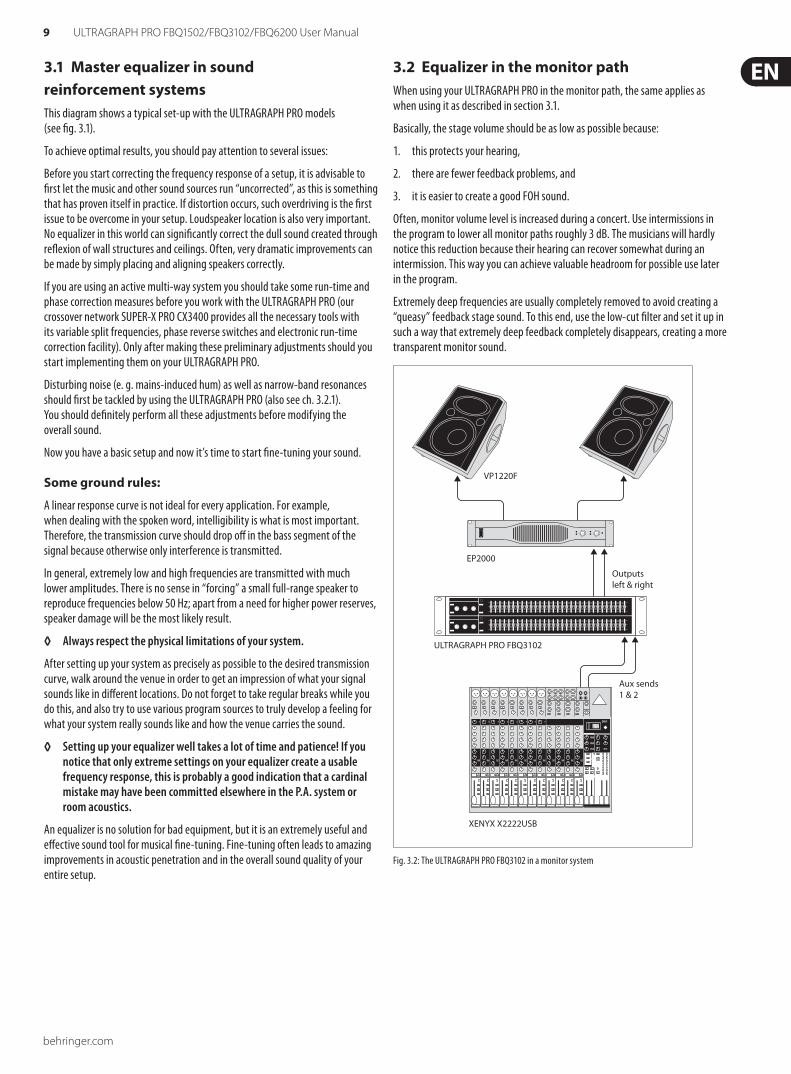
Equalizer in the monitor path3.2 When using your ULTRAGRAPH PRO in the monitor path, the same applies as when using it as described in section 3.1.
Basically, the stage volume should be as low as possible because:
this protects your hearing,1.
there are fewer feedback problems, and2.
it is easier to create a good FOH sound.3.
Often, monitor volume level is increased during a concert. Use intermissions in the program to lower all monitor paths roughly 3 dB. The musicians will hardly notice this reduction because their hearing can recover somewhat during an intermission. This way you can achieve valuable headroom for possible use later in the program.
Extremely deep frequencies are usually completely removed to avoid creating a “queasy” feedback stage sound. To this end, use the low-cut filter and set it up in such a way that extremely deep feedback completely disappears, creating a more transparent monitor sound.
VP1220F
EP2000
ULTRAGRAPH PRO FBQ3102
XENYX X2222USB
Outputsleft & right
Aux sends1 & 2
Fig. 3.2: The ULTRAGRAPH PRO FBQ3102 in a monitor system
behringer.com
10 ULTRAGRAPH PRO FBQ1502/FBQ3102/FBQ6200 User Manual
Priming a monitor system3.2.1
Priming describes the process of detecting and supressing feedback frequencies. After placing and leveling your mics and monitors (incl. power amps), you should crank up the aux send controls of your mixer.
Now, activate the FBQ feedback detection system by pressing the FBQ switch [3]. The slide control LEDs [9] will turn dark. Then, increase the amplification on your mixer by using the aux send master control until you notice feedback starting to occur. Feedback frequencies will now be easily visible through intensive lighting of the relevant LEDs.
Pull down the slide controls whose LEDs are lit until the feedback subsides. Repeat this procedure to weed out other possible feedback frequencies. After having adjusted all critical frequencies, when you crank up the aux send master control, you will be able to hear only the initial multi-frequency feedback. Your monitors have reached their maximum volume.
Leave all other faders in the middle position as long as no need for frequency correction occurs (e.g. measuring with a real-time analyzer). Set the desired stage volume, and you will have a tremendous amount of headroom available to you, without creating audible feedback.
Using the ULTRAGRAPH PRO in the studio3.3 Additional applications await the ULTRAGRAPH PRO models in the studio. No limits stand in the way of your imagination. Here are just a few examples of possible uses:
EQing your studio monitors:
You can conduct a graphic equalization of your monitors. Besides, you can supress narrow-band room resonance. An analyzer, for example the analyzer integrated into our digital equalizer ULTRACURVE PRO DEQ2496, can help you when you are looking for room resonance and a linear frequency response.
General sound processing:
Equalizers can be used to process both single-channel and master signals. To process single-channel signals, you should connect the ULTRAGRAPH PRO via the channel inserts on your mixer. To control several signals with your ULTRAGRAPH PRO, use either subgroup or main mix inserts. Nowadays, the overall sound of a mix is often “tweaked” with equalizers. Often, a mix is not uniform, that is, frequency ranges are either too prominent or not prominent at all. A graphic equalizer lets you find a fitting ratio between the intensity of these various frequency ranges in order to achieve a homegenous sound.
Special sound effects3.4 In recording studios as well as stage or radio plays, the ULTRAGRAPH PRO will be your valuable sound tool for modifying the sound of voices (e.g. telephone voice) or to filter instruments so that they fit in an existing mix.
The tables on the separate add-on sheet give you an idea of specific frequencies and their acoustic significance, and suggest some possible uses for your ULTRAGRAPH PRO.
Installation4. Rack mounting 4.1
The FBQ1502 requires one height unit (1 HU) for mounting in a 19" rack, the FBQ3102 two height units, and the FBQ6200 three height units. Please allow at least an additional 4" of space for the connectors on the back panel.
Be sure that there is enough space around the unit for cooling and please do not place your ULTRAGRAPH PRO on high-temperature devices such as power amplifiers etc. to avoid overheating.
For rack mounting, please use M6 metal nuts and bolts.
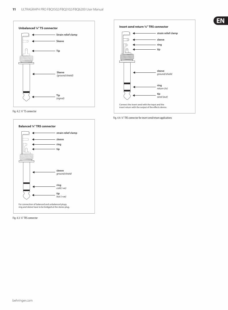
Audio connections4.2 You will need many different cables for the various applications. The following illustrations show how these cables should be laid out. Please use exclusively high-grade cabels.
The ULTRAGRAPH PRO is installed with electronically servo-balanced inputs and outputs to avoid hum noise problems.
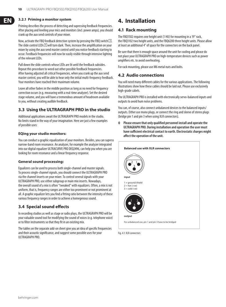
You can, of course, also connect unbalanced devices to the balanced inputs/outputs. Either use mono plugs, or connect the ring and sleeve of stereo plugs (bridge pin 1 and pin 3 when using XLR connectors).
Please ensure that only qualified personnel install and operate the ◊ ULTRAGRAPH PRO. During installation and operation the user must have sufficient electrical contact to earth. Electrostatic charges might affect the operation of the unit.
output
For unbalanced use, pin 1 and pin 3 have to be bridged
1 = ground/shield2 = hot (+ve)3 = cold (-ve)
input
123
1 2
3
Balanced use with XLR connectors
Fig. 4.1: XLR connectors
11 ULTRAGRAPH PRO FBQ1502/FBQ3102/FBQ6200 User Manual
behringer.com
Strain relief clamp
Sleeve
Tip
Sleeve(ground/shield)
Unbalanced ¼" TS connector
Tip(signal)
Fig. 4.2: ¼" TS connector
strain relief clamp
sleeve
ring
tip
sleeveground/shield
For connection of balanced and unbalanced plugs,ring and sleeve have to be bridged at the stereo plug.
Balanced ¼" TRS connector
ringcold (-ve)
tiphot (+ve)
Fig. 4.3: ¼" TRS connector
strain relief clamp
sleeve
ring
tip
sleeveground/shield
Connect the insert send with the input and theinsert return with the output of the effects device.
Insert send return ¼" TRS connector
ringreturn (in)
tipsend (out)
Fig. 4.4: ¼" TRS connector for insert send/return applications
behringer.com
12 ULTRAGRAPH PRO FBQ1502/FBQ3102/FBQ6200 User Manual
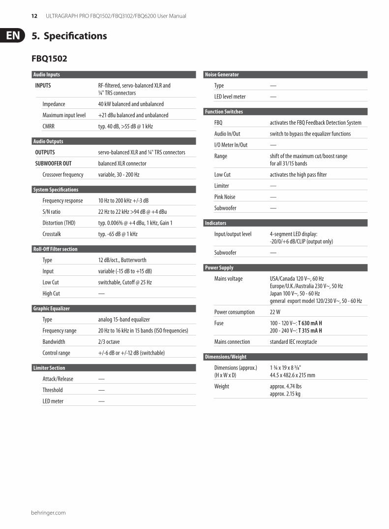
Specifications5.
FBQ1502
Audio Inputs
INPUTS RF-filtered, servo-balanced XLR and ¼" TRS connectors
Impedance 40 kW balanced and unbalanced
Maximum input level +21 dBu balanced and unbalanced
CMRR typ. 40 dB, >55 dB @ 1 kHz
Audio Outputs
OUTPUTS servo-balanced XLR and ¼" TRS connectors
SUBWOOFER OUT balanced XLR connector
Crossover frequency variable, 30 - 200 Hz
System Specifications
Frequency response 10 Hz to 200 kHz +/-3 dB
S/N ratio 22 Hz to 22 kHz >94 dB @ +4 dBu
Distortion (THD) typ. 0.006% @ +4 dBu, 1 kHz, Gain 1
Crosstalk typ. -65 dB @ 1 kHz
Roll-Off Filter section
Type 12 dB/oct., Butterworth
Input variable (-15 dB to +15 dB)
Low Cut switchable, Cutoff @ 25 Hz
High Cut —
Graphic Equalizer
Type analog 15-band equalizer
Frequency range 20 Hz to 16 kHz in 15 bands (ISO frequencies)
Bandwidth 2/3 octave
Control range +/-6 dB or +/-12 dB (switchable)
Limiter Section
Attack/Release —
Threshold —
LED meter —
Noise Generator
Type —
LED level meter —
Function Switches
FBQ activates the FBQ Feedback Detection System
Audio In/Out switch to bypass the equalizer functions
I/O Meter In/Out —
Range shift of the maximum cut/boost range for all 31/15 bands
Low Cut activates the high pass filter
Limiter —
Pink Noise —
Subwoofer —
Indicators
Input/output level 4-segment LED display: -20/0/+6 dB/CLIP (output only)
Subwoofer —
Power Supply
Mains voltage USA/Canada 120 V~, 60 Hz Europe/U.K./Australia 230 V~, 50 Hz Japan 100 V~, 50 - 60 Hz general export model 120/230 V~, 50 - 60 Hz
Power consumption 22 W
Fuse 100 - 120 V~: T 630 mA H 200 - 240 V~: T 315 mA H
Mains connection standard IEC receptacle
Dimensions/Weight
Dimensions (approx.) 1 ¾ x 19 x 8 3/8" (H x W x D) 44.5 x 482.6 x 215 mm
Weight approx. 4.74 lbs approx. 2.15 kg
13 ULTRAGRAPH PRO FBQ1502/FBQ3102/FBQ6200 User Manual
behringer.com
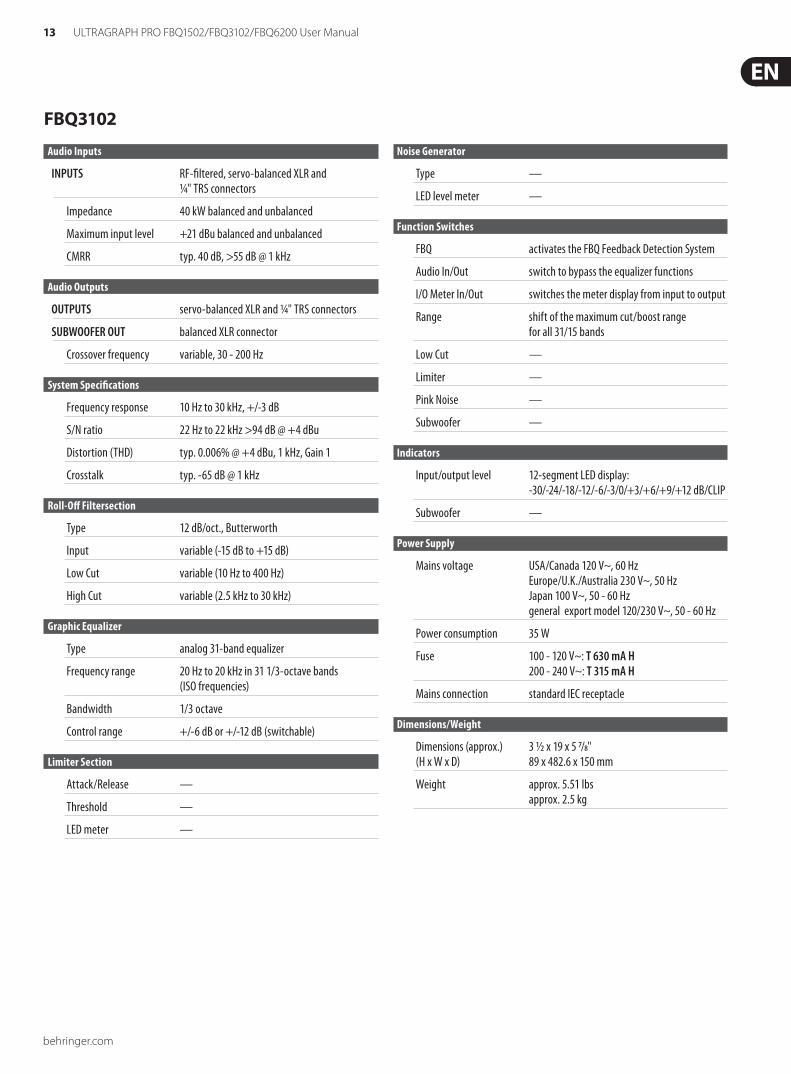
FBQ3102
Audio Inputs
INPUTS RF-filtered, servo-balanced XLR and ¼" TRS connectors
Impedance 40 kW balanced and unbalanced
Maximum input level +21 dBu balanced and unbalanced
CMRR typ. 40 dB, >55 dB @ 1 kHz
Audio Outputs
OUTPUTS servo-balanced XLR and ¼" TRS connectors
SUBWOOFER OUT balanced XLR connector
Crossover frequency variable, 30 - 200 Hz
System Specifications
Frequency response 10 Hz to 30 kHz, +/-3 dB
S/N ratio 22 Hz to 22 kHz >94 dB @ +4 dBu
Distortion (THD) typ. 0.006% @ +4 dBu, 1 kHz, Gain 1
Crosstalk typ. -65 dB @ 1 kHz
Roll-Off Filtersection
Type 12 dB/oct., Butterworth
Input variable (-15 dB to +15 dB)
Low Cut variable (10 Hz to 400 Hz)
High Cut variable (2.5 kHz to 30 kHz)
Graphic Equalizer
Type analog 31-band equalizer
Frequency range 20 Hz to 20 kHz in 31 1/3-octave bands (ISO frequencies)
Bandwidth 1/3 octave
Control range +/-6 dB or +/-12 dB (switchable)
Limiter Section
Attack/Release —
Threshold —
LED meter —
Noise Generator
Type —
LED level meter —
Function Switches
FBQ activates the FBQ Feedback Detection System
Audio In/Out switch to bypass the equalizer functions
I/O Meter In/Out switches the meter display from input to output
Range shift of the maximum cut/boost range for all 31/15 bands
Low Cut —
Limiter —
Pink Noise —
Subwoofer —
Indicators
Input/output level 12-segment LED display: -30/-24/-18/-12/-6/-3/0/+3/+6/+9/+12 dB/CLIP
Subwoofer —
Power Supply
Mains voltage USA/Canada 120 V~, 60 Hz Europe/U.K./Australia 230 V~, 50 Hz Japan 100 V~, 50 - 60 Hz general export model 120/230 V~, 50 - 60 Hz
Power consumption 35 W
Fuse 100 - 120 V~: T 630 mA H 200 - 240 V~: T 315 mA H
Mains connection standard IEC receptacle
Dimensions/Weight
Dimensions (approx.) 3 ½ x 19 x 5 7/8" (H x W x D) 89 x 482.6 x 150 mm
Weight approx. 5.51 lbs approx. 2.5 kg
behringer.com
14 ULTRAGRAPH PRO FBQ1502/FBQ3102/FBQ6200 User Manual
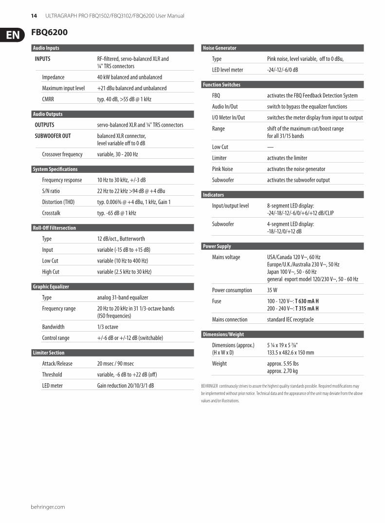
FBQ6200
Audio Inputs
INPUTS RF-filtered, servo-balanced XLR and ¼" TRS connectors
Impedance 40 kW balanced and unbalanced
Maximum input level +21 dBu balanced and unbalanced
CMRR typ. 40 dB, >55 dB @ 1 kHz
Audio Outputs
OUTPUTS servo-balanced XLR and ¼" TRS connectors
SUBWOOFER OUT balanced XLR connector, level variable off to 0 dB
Crossover frequency variable, 30 - 200 Hz
System Specifications
Frequency response 10 Hz to 30 kHz, +/-3 dB
S/N ratio 22 Hz to 22 kHz >94 dB @ +4 dBu
Distortion (THD) typ. 0.006% @ +4 dBu, 1 kHz, Gain 1
Crosstalk typ. -65 dB @ 1 kHz
Roll-Off Filtersection
Type 12 dB/oct., Butterworth
Input variable (-15 dB to +15 dB)
Low Cut variable (10 Hz to 400 Hz)
High Cut variable (2.5 kHz to 30 kHz)
Graphic Equalizer
Type analog 31-band equalizer
Frequency range 20 Hz to 20 kHz in 31 1/3-octave bands (ISO frequencies)
Bandwidth 1/3 octave
Control range +/-6 dB or +/-12 dB (switchable)
Limiter Section
Attack/Release 20 msec / 90 msec
Threshold variable, -6 dB to +22 dB (off)
LED meter Gain reduction 20/10/3/1 dB
Noise Generator
Type Pink noise, level variable, off to 0 dBu,
LED level meter -24/-12/-6/0 dB
Function Switches
FBQ activates the FBQ Feedback Detection System
Audio In/Out switch to bypass the equalizer functions
I/O Meter In/Out switches the meter display from input to output
Range shift of the maximum cut/boost range for all 31/15 bands
Low Cut —
Limiter activates the limiter
Pink Noise activates the noise generator
Subwoofer activates the subwoofer output
Indicators
Input/output level 8-segment LED display: -24/-18/-12/-6/0/+6/+12 dB/CLIP
Subwoofer 4-segment LED display: -18/-12/0/+12 dB
Power Supply
Mains voltage USA/Canada 120 V~, 60 Hz Europe/U.K./Australia 230 V~, 50 Hz Japan 100 V~, 50 - 60 Hz general export model 120/230 V~, 50 - 60 Hz
Power consumption 35 W
Fuse 100 - 120 V~: T 630 mA H 200 - 240 V~: T 315 mA H
Mains connection standard IEC receptacle
Dimensions/Weight
Dimensions (approx.) 5 ¼ x 19 x 5 7/8" (H x W x D) 133.5 x 482.6 x 150 mm
Weight approx. 5.95 lbs approx. 2.70 kg
BEHRINGER continuously strives to assure the highest quality standards possible. Required modifications may
be implemented without prior notice. Technical data and the appearance of the unit may deviate from the above
values and/or illustrations.
behringer.com