Embed Size (px)
Citation preview

Ultracapacitor Applications and Evaluation for Hybrid Electric Vehicles
Ahmad Pesaran([email protected])
Jeff Gonder, Matt KeyserNational Renewable Energy Laboratory
Presented at the 7th Annual Advanced Capacitor World Summit ConferenceNREL/PR-540-45596
NREL is a national laboratory of the U.S. Department of Energy, Office of Energy Efficiency and Renewable Energy, operated by the Alliance for Sustainable Energy, LLC.

2
Discussion Points
• Discussion of batteries vs. ultracapacitors for advanced vehicles
• Simulation results of HEV fuel economy impact from reducing the storage system’s energy window
• 15%-30% HEV fuel economy improvements with 50-100 Wh ultracapacitors
• Evaluation of lithium ion capacitors for HEV applications
• Thermal evaluation of a high-voltage ultracapacitor module for start-stop applications
3
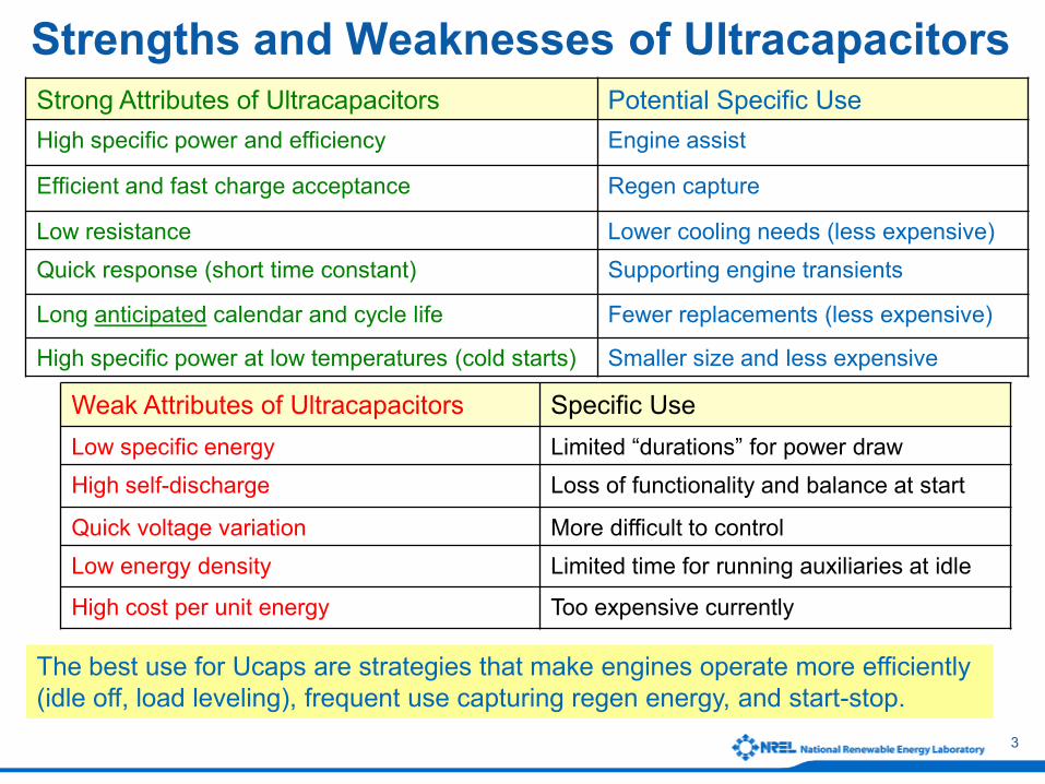
Strong Attributes of Ultracapacitors Potential Specific UseHigh specific power and efficiency Engine assist
Efficient and fast charge acceptance Regen capture
Low resistance Lower cooling needs (less expensive)Quick response (short time constant) Supporting engine transients
Long anticipated calendar and cycle life Fewer replacements (less expensive)
High specific power at low temperatures (cold starts) Smaller size and less expensive
Weak Attributes of Ultracapacitors Specific UseLow specific energy Limited “durations” for power drawHigh self-discharge Loss of functionality and balance at start
Quick voltage variation More difficult to controlLow energy density Limited time for running auxiliaries at idle
High cost per unit energy Too expensive currently
The best use for Ucaps are strategies that make engines operate more efficiently (idle off, load leveling), frequent use capturing regen energy, and start-stop.
Strengths and Weaknesses of Ultracapacitors

4
A Couple of Thoughts
• Taking advantage of an ultracapacitor’s strengths while minimizing the impact of its weaknesses to make its “value” competitive with batteries
• It should be for a specific application to show “value” in terms of “life-cycle cost”
— Fuel economy— Replacement cost— Life— Durability and reliability— Quality— Functionality

5
Event How Much Energy Needed
Assist:20/30 kW constant power for 15/10 s 83.3 Wh
Accessory: 3 kW constant draw for 1 minute 50
Accessory: 1 kW constant draw for 1 minute 16.7
2% Grade going 35 mph for 1 minute Ŧ 70 Wh4% Grade going 35 mph for 1 minute Ŧ 170 Wh US06 Driving Cycle * 155 Wh
UDDS Driving Cycle * 80 Wh
Ucap Is Energy Limited!How Much Energy Is Needed for Various Events?
Prius has a 1.4 kWh NiMH battery but capacity is for life margin and warranty.Vue mild hybrid has a 0.6 kWh NiMH battery.
•Total Energy (at wheels) calculated for 1520 kg vehicle (regen); 50% of energy in the cycle’s largest deceleration eventCold-start capability is expected to dictate the size of batteries, but not the case for Ucap.
Ŧ Note: Engine provides propulsion up a grade, the estimate is for capturing regen to hold a 1520 kg vehicle speed going down a grade.

6
Potential Use of Ultracapacitors in Light-Duty Electric-Drive Vehicles
NiMH and Li-ion: YesUcap: LikelyUcap + VRLA: Possible
Micro Hybrids (12 V-42 V: Start-Stop, Launch Assist)
Li-ion: YesUcaps + high energy Li-ion : Possible
Plug-in HEV (EV)
NiMH and Li-ion: Yes Ucaps: Likely if Fuel Cell is not downsizedUcaps + (NiMH or Li-Ion): Possible
Fuel Cell Hybrids
NiMH and Li-ion: YesUcaps: Possible Ucaps + (NiMH or Li-Ion): Possible
Full Hybrids (150 V-350 V: Power Assist HEV)
NiMH and Li-ion: YesUcaps: Likely if engine is not downsizedUcaps + VRLA: Possible
Mild Hybrids (42 V-150 V: Micro HEV Function + Regen)
15-25 Wh
25-70 Wh
60-150 Wh
60-150 Wh
5-20 kWh(50-90 Wh*)
Min energy needed
* Energy for a Ucap in combination withLi-Ion

7
Analyzing the Impact of Energy Window on Power-Assist HEVs
• Motivation: Investigate the relation between in-use energy window and fuel economy (a request from USABC/FreedomCAR)
• Approach: Simulate a midsize sedan with different component power levels and control settings for different drive cycles using PSAT
Midsize Car Assumptions
Mass = 1675 kgEngine = 90 kWRESS/Motor = 30 kWElec accessories = 500 WMech accessories = 230 W
FA = 2.27 m2
CD = 0.30Crr1 = 0.008Crr2 = 0.00012
Simulated different ES energy content cases with the otherwise constant platform values
Constant 30 kW power changing P/E ratio
Smallest ES energy
Largest ES energy
Wh
Upper threshold
Target level
Lower threshold
Constant SOC-based controls (charge sustaining)
Changing Wh control window toleranceSource: J. Gonder, Presentation to USABC, July 19, 2007

8
Definition of ES Energy Window Use (for a drive cycle or event)
Energy out for electric launch/assist
Cum
ulat
ive
RES
S W
h to
veh
icle
RESS use indicated by slope of energy line
Energy return from charging/regen
“Energy window” defined by (max – min) for the
particular cycle
(not “target window” from control strategy)
Charge sustaining over cycle
(no net energy use)
Energy Window Used ≤ Available EnergySource: J. Gonder, Presentation to USABC, July 19, 2007

9
US06 Cycle
0 500 1000 1500-20
0
20
40
60
80
time (s)
Vehicle speed (mph)Cycle grade (%)
• Mean power during:Propulsion = 21 kWDeceleration = -17 kW
• No grade
“NREL to Genesee Cycle”
Aggressive driving
Up and down, foothills driving
0 200 400 6000
20
40
60
80
100
time
Vehicle speed (mph)
time (s)
• Mean power during:Propulsion = 23 kWDeceleration = -12 kW
• Considerable grade
0 500 1000 15000
20
40
60
time (s)
Vehicle Speed (mph)
UDDS CycleMild urban driving
• Mean power during:Propulsion = 7 kWDeceleration = -5 kW
• No grade
p
Constant 30 kW power changing P/E ratio
Smallest ES energy
Largest ES energy
p
Constant 30 kW power changing P/E ratio
Smallest ES energy
Largest ES energy
Source: J. Gonder, Presentation to USABC, July 19, 2007
Three Cycles Simulated to Observe Energy Window and Fuel Use

10
On City Cycle (UDDS), Large Fuel Savings Result from Hybridization
6.50
7.50
8.50
9.50
10.50
11.50
12.50
0 100 200 300 400ESS Energy Window (Wh)
Fuel
Con
sum
ptio
n (L
/100
km
)
(mpg
refe
renc
e)
18.8
20.5
22.4
24.8
27.7
31.4
36.2
Conventional Vehicle
Smallest RESS case
Largest RESS case
21% decrease
18% decrease
RESS Energy Window (Wh)Source: J. Gonder, Presentation to USABC, July 19, 2007

11
6.50
7.50
8.50
9.50
10.50
11.50
12.50
0 50 100 150 200 250 300 350 400
ESS Energy Window (Wh)
Fuel
Con
sum
ptio
n (L
/100
km
)
(mpg
refe
renc
e)
18.8
20.5
22.4
24.8
27.7
31.4
36.2
Summary Results of ES Energy Window and Fuel Economy Simulations
UDDS Cycle
US06 Cycle
Foothills Driving
Same Vehicle (largest RESS)
Same Vehicle (smallest RESS)
Same Vehicle (conventional)
RESS Energy Window (Wh)
Source: J. Gonder, Presentation to USABC, July 19, 2007

12
3
4
5
6
7
8
9
10
11
0 100 200 300 400 500 600 700
Energy Window (Wh)
Fuel
Con
sum
ptio
n (L
/100
km)
Fuel Economy (m
pg)
58.81
47.0
39.20
33.60
29.40
26.14
23.52
21.3
78.41
Charge SustainingNot Charge SustainingUDDSUS 06HWFTMTSS Speeds
Prius Camry Escape Accord
All the charge sustaining (CS) tests use windows <200 Wh(for these vehicles and CS cycles)
Test data analysis seems to validate simulation finding of significant hybridization
benefit in the 50-150 Wh range
Vehicle Test Results: Battery Energy Use for Today’s HEVs under Various Drive Cycles
Prius and Escape Test Data: Tony Markel, NRELCamry and Accord Test Data: Mike Duoba, ANLTest Data Analysis: Jaehun Rhee and Jeff Gonder, NREL
Source: J. Gonder, Presentation to USABC, July 19, 2007

13
2007 Mild Hybrid Dyno Data* Analysis Indicates <50 Wh Energy Use for Typical
Driving—Already Reasonable Ucap RangeDriving Energy Analysis (UDDS cycle example)
Energy window
* Department of Energy-sponsored dynamometer testing

14
Mild and Power-Assist Hybrids with Ucaps
• It is possible to use ultracapacitors (with available energy of 50-150 Wh) in power-assist HEVs with modest fuel economy improvements
— However, acceleration and passing on grade performance considerations could be limiting factors
• 15%-30% HEV fuel economy improvements with 50-100 Wh ultracapacitors
• A project is underway on a vehicle to demonstrate Ucaps in mild hybrids
— To be discussed in future meetings

15
0
2
4
6
8
10
12
14
16
18
20
0 100 200 300 400 500 600time (s)
Vo
lta
ge
(V
)
Hybrid Pack – UC VoltageBattery-only – Voltage
Previous NREL Tests Have Shown That Combining Ultracapacitors Filters High Current Transients In Batteries
Source: M. Zolot (NREL Reports and 2003 Florida Capacitor Seminar)
Ultracapacitor module of 8 cells (up to 20V) and two 6.5Ah NiMH module of 14.4V (18V max). Ultracap module and battery pack were arranged in parallel to share the current load depending on internal impedance.
0
5
10
15
20
25
30
35
40
45
-40 to -110
-30 -20 -10 0 10 20 30 40 to100
Current (A)
g g g
% Freq Hyb_NiMH % Freq Bat_NiM
ChargeDischarge
Battery-only - Battery Current
Hybrid Pack - Battery Current
• Overall, batteries in the hybrid pack experienced no currents larger than ±40 A, while the batteries in traditional pack saw currents up to ±110 A.
• Up to 33% narrower battery SOC cycling range was observed in hybrid pack; this has the potential to increase battery life.
Parallel connection; no DC/DC converterMay not be practical to implement in vehicles.

16
Advantages/Disadvantages ofHybridizing Energy Storage (Ucap + Battery)
Advantages• Reduced battery currents• Reduced battery cycling range• Increased battery cycle/calendar life (to
what extent?)• Increased combined power and energy
capabilities• Lower cooling requirements• Better low-temperature performanceDisadvantages• Complex control strategy• Larger volume & mass• Need for electronics for each system• Increased energy storage cost• Unknown side effects if directly coupled• Any need for DC/DC converters adds
even more cost and complexity
+
UcapModule
+
BatteryModule
DC
DCDC
+EM14V
Energy Storage Subsystem
EE300-20
AC
Power
DC
DC
UUCap > UBatt
DC
DC
UUcap > UBatt+
UcapModule
+
BatteryModule
DC
DCDC
+EM14V
Energy Storage SubsystemEnergy Storage Subsystem
EE300-20
AC
Power
DC
DC
UUCap > UBatt
Power
DC
DC
Power
DC
DC
UUCap > UBattUUCap > UBatt
DC
DC
UUcap > UBattUUcap > UBatt
Source: Continental ISAD, “New Energy Storage Concept,” Proceedings of AABC-04

17
• JSR Micro contacted us to express interest in thermal characterization of their asymmetric capacitor
• JSR Micro claimed higher energy than C-C Ucaps with the same power capability
• We received 3 cells for characterization per USABC protocols
Thermal/Electrical Characterization ofJSR Micro Lithium Ion Capacitor (LIC)
Source: www.jmenergy.co.jp/en/product.html

18
JSR Micro LIC Cell Characteristics
Cell 1 0.205 2.669 5.5" x 4" x 0.330" 1.58Cell 2 0.205 2.669 5.5" x 4" x 0.330" 1.62Cell 3 0.205 2.672 5.5" x 4" x 0.330" 1.6
Impedance (mOhms)Cell Number
(#) Mass (kg)Voltage (Volts)
Dimensions (inches)
Nominal 2200 F14 Wh/kg3.8 V – 2.2 V Source: www.jmenergy.co.jp/en/product.html
19
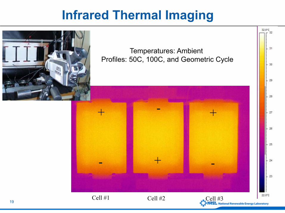
Infrared Thermal Imaging
+ -
+
Cell #1 Cell #2 Cell #3
-
--
+
+
+
Temperatures: AmbientProfiles: 50C, 100C, and Geometric Cycle

20
Thermal Image and Thermal Lines of 3 LIC Cells – 100 A Discharge

21
Thermal Characterization in NREL Calorimeter Lithium Ion Capacitor 2200 F Cells
•Temperatures: +30˚C• Profiles: CC discharge cycles
0 0.5 1 1.5 2 2.5 3 3.5 4
Time (Hours)
Calorimeter Response to Constant Current Charge/Discharge
Hea
t Gen
erat
ion
Discharge - Exothermic
Charge - Endothermic
Increasing Discharge Current
Increasing Charge Current

22
Electrical Characterization: Lithium Ion Capacitor Cells
• C/1, 10 C, 100 C, and HPPC Testing
2
2.2
2.4
2.6
2.8
3
3.2
3.4
3.6
3.8
0 10 20 30 40 50 60 70 80 90 100DOD (%)
OC
V (V
olts
)
Energy: 14 Wh/kg
Power: 1500 W/kg
This asymmetric capacitor had high resistance; the next generation is claimed to be better.
2200 F cell 0 20 40 60 80 100 120Depth of Discharge (%)
Discharge Regen
Pow
er
HPPC Discharge/Regen Power
0.7
0.75
0.8
0.85
0.9
0.95
1
0 20 40 60 80 100 120Current (Amps)
Dis
char
ge C
apac
ity (A
h)
Cell #1 Cell #2 Cell #3

23
Expected Calendar Life of Typical Current EDLC TechnologyMuch Better Than Batteries if Stored at Low Voltages
70 C
60 C
50 C
40 C30 C
Clamped Voltage
Expe
cted
Cal
enda
r Life
(Yea
rs) Source: Anderman, 2004 Advanced
Automotive Battery Conference
24
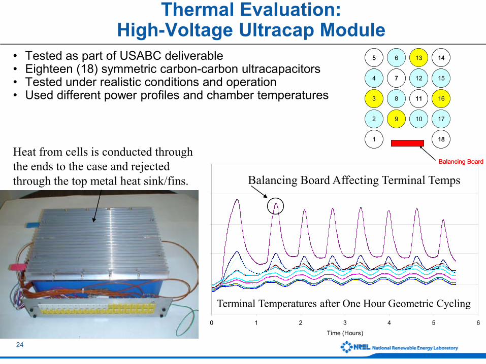
Thermal Evaluation: High-Voltage Ultracap Module
• Tested as part of USABC deliverable• Eighteen (18) symmetric carbon-carbon ultracapacitors• Tested under realistic conditions and operation• Used different power profiles and chamber temperatures
5
0
5
0
5
0
0 1 2 3 4 5 6
Time (Hours)
Terminal Temperatures after One Hour Geometric Cycling
5 6 13 14
4 7 12 15
3 8 11 16
2 9 10 17
1 18
Balancing Board
5 6 13 14
4 7 12 15
3 8 11 16
2 9 10 17
1 18
Balancing Board
Balancing Board Affecting Terminal Temps
Heat from cells is conducted through the ends to the case and rejected through the top metal heat sink/fins.

25
Thermal Evaluation: High-Voltage Ultracap Module
• Continuous US06 cycling for two hours • Balancing board did a good job equalizing cells• Energy drain for balancing could be a concern
0
5
10
15
20
25
30
35
40
45
0 2 4 6 8 10 12 14 16 18 20Time (Hours)
Bal
ance
Boa
rd T
empe
ratu
re (
C)_
0
0.01
0.02
0.03
0.04
0.05
0.06
0.07
Max
to M
in C
ell V
olta
ge (
Vol
ts)_
Balance Board Temp
Max to Min Voltage Difference
29
30
31
32
33
34
35
36
0 1 2 3 4 5 6Time (Hours)
Te
rmin
al T
em
pe
ratu
re (
C)
Cell Terminal #1 Cell Terminal #3 Cell Terminal #5 Cell Terminal #7 Cell Terminal #9Cell Terminal #11 Cell Terminal #13 Cell Terminal #14 Cell Terminal #16 Cell Terminal #18
Cell #1
Interior Cells
Exterior Cells
(next to balancing board)
Temperature difference less than 1.5°C except for Cell #1 which heated due to balancing board.
26
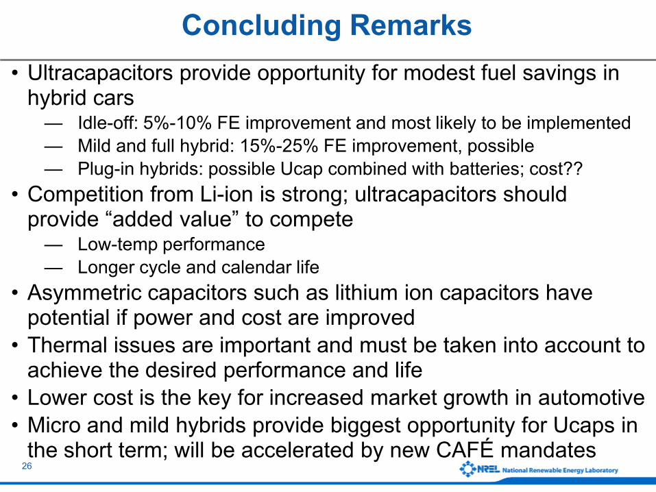
Concluding Remarks• Ultracapacitors provide opportunity for modest fuel savings in
hybrid cars— Idle-off: 5%-10% FE improvement and most likely to be implemented— Mild and full hybrid: 15%-25% FE improvement, possible— Plug-in hybrids: possible Ucap combined with batteries; cost??
• Competition from Li-ion is strong; ultracapacitors should provide “added value” to compete
— Low-temp performance— Longer cycle and calendar life
• Asymmetric capacitors such as lithium ion capacitors have potential if power and cost are improved
• Thermal issues are important and must be taken into account to achieve the desired performance and life
• Lower cost is the key for increased market growth in automotive• Micro and mild hybrids provide biggest opportunity for Ucaps in
the short term; will be accelerated by new CAFÉ mandates

27
Acknowledgements
• Support provided by FreedomCAR and Fuel Partnership in the Vehicle Technologies Program of the U.S. Department of Energy
— David Howell, Energy Storage Technology Manager
• Technical insight and support— Harshad Tataria, USABC/GM— Jim Banas, JSR Micro Inc.
nrel.gov/vehiclesandfuels/energystorage/publications.html