Embed Size (px)
Citation preview

Ultra micro Sopwith Triplane
This kit requires following parts:
Receiver:
AR6400***http://www.parkzone.com/Products/Default.aspx?ProdID=SPMAR6400
Receiver for Vapor, Champ, J-3 Cubhttp://www.parkzone.com/Products/Default.aspx?ProdID=PKZ3351
Receiver for Night vaporhttp://www.parkzone.com/Products/Default.aspx?ProdID=PKZUA1151
8.5mm Motor/gear box
http://www.parkzone.com/Products/Default.aspx?ProdID=PKZ3624
http://www.horizonhobby.com/Products/Default.aspx?ProdID=HBZ4930
130x70 Propeller
Parkzone UM P-51,T-28, Sukhoi XPE-flite 4-site, Hobbyzone Champ.http://www.parkzone.com/Products/Default.aspx?ProdID=EFL9051
150mah-160mah Lipo Battery
Hyperion G3 CX-1s 160mah (4.55g)http://www.hyperion-world.com/products/product/HP-LG325-0160-1S-UM
E-flite 150mah (4.3g)http://www.parkzone.com/Products/Default.aspx?ProdID=EFLB1501S
Summary of parts you can use from common RTF/BNF products:
Hobbyzone champ:Receiver, motor/gearbox, propeller, battery
Parkzone UM P-51:Receiver***, motor/gearbox, propeller
Parkzone UM T-28:Receiver***, motor/gearbox, propeller
Parkzone UM F4U:Receiver***, motor/gearbox, battery
Parkzone Sukhoi XP:Receiver***, motor/gearbox, Propeller, Battery
Parkzone Night Vapor/Vapor/ Ember 2/J-3 Cub:Receiver
Eflite 4-site:Receiver***, motor, battery
***The AR6400 requires transmitter programming to allow the rudder to be controlled by the aileron stick. You will need a transmitter with mixing capability such as the DX6i, DX7, or DX8. The DX5e or stock transmitters that come with HobbyZone or ParkZone RTF products are not recommended.
1
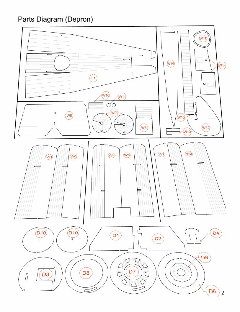
Parts Diagram (Depron)
2

Spar
eSp
are
Spar
e
Par
ts D
iagr
am (B
alsa
)
3

Required Tools & Glues
Foam Safe contact glue
Beacon Foam-Tachttp://www.rcfoam.com/product_info.php?products_id=1243
http://www.beaconadhesives.com/cgfoam.html
UHU por (UHU creative)http://www.rcfoam.com/product_info.php?products_id=277
In general, the above glues are best for Foam to Foam bonding or Foam to Balsa. bonding
Foam Safe CA
Balsa to Balsa or Balsa to CF rods bonds works best with CA. However for applications such as gluing control horns to foam control surfaces, Foam Safe CA is recommended. Never use regular CA to glue foam parts.
Tools
Hobby knife
All the kit parts are laser cut , therefore no cutting will be necessary but you will need a hobby knife to cut parts loose from the carrier sheet.
Sandpaper
You will need it to sand the nose of the airplane (cowl). I prefer to use very coarse grit sand papers, such as above 200 grit.
Long nose pliers or hemostat
Used when mounting propellers.
Diagonal cutter
Used when cutting the gear box flange.
Using Glue applicator
The kit is supplied with 5 CA applicator(B31) in balsa parts sheet. Put a few drops of CA in a container, such as fast food sauce container or bottle cap and dip glue applicator. As shown in the photo, the glue applicator will hold small amount of CA. This tool will be useful in all CA application in this kit.
Before you start
Please pay attention to following building process. It is very important to understand each step and the overall sequence. In this regard, I recommend thoroughly reading this manual, and carefully studying the accompanying photographs.
Common mistakes:
1. Building two left or two right wing structures.\
2. Gluing the battery bay onto the wrong side of the battery cover
3. Opening on fire wall is on the wrong side
4. Attaching the brick (receiver) to the wrong side of the fuselage.
How do I know this? I have done it myself.
I hope you have great time with this kit!
4

Building Wing structure
B5B3
B3
B2B5B6
B1
Start by building the wing structure jig on a flat surface as shown above.
Prepare the Cabane Struts by reaming the holes with the supplied CF rods.
Building The Left Wing Frame
L OUTB7
L INB8
Prepare parts as shown. Strut labeled ‘L OUT (B7)’ is placed on the LEFT side of the jig. ‘L IN(B8)’ is placed on the RIGHT.
Insert the Cabane Struts into the jig slots with the lower ends touching the studs (vertical pieces). The labeled sides must face left as shown.
Lower end should touch stud as shown.
5

Insert carbon rod (158mm) spars as shown. The diagonal brace (129mm) should be laid over the middle spar.Apply CA Glue from the right side of the struts since wing ribs will be attached to the left hand side. Do not glue lower right end at this moment. Wing spar: 158mmDiagonal brace: 129mm
Building The Right wing frame
R OUTB9 B10
R IN
Prepare struts as shown. The same jig that used for the left wing frame will be used.
Notice how the cabane struts are laid on the jig. ‘R IN(B10)’ goes to right hand side and ‘R OUT(B9)’ should be placed on the left. Again, the labeled side face left.
Lower end meets the stud (B6) as shown.
Insert carbon rod spars (158mm). Diagonal brace (129mm) should be laid under the middle spar.Apply CA Glue from right side since wing ribs will be attached to the left hand side. Again do not glue lower right end
6

Building The Fuselage
Crease the fuselage front as shown. Since the fuselage inside is scored with Laser engraver, creases will form at the scored lines. The creased lines will simulate a fabric covered wooden frame.
Crease fuselage tail. Crease will simulate the look of fabric covered turtle deck.
Glue front edges together, and fold border between turtle deck and side to 90 degrees or more.
D1
D2
D3
Assemble the firewall and cabane strut mounting plate together as shown.
Above photo is a view of the back of the firewall and cabane strut mounting plate. Apply glue as shown.
Attach fuselage skin to fire wall and top edge of cabane strut mounting plate.
7

Make sure the skin is centered around firewall as shown on photo above.
Glue the tail of the fuselage together.
Glue ‘H’ shaped tail former(D4) and complete fuselage. Fuselage bottom cover will be attached at a later stage.
Mounting The Cabane Struts To The Fuselage
Install the Cabane Struts following the steps shown on the next page.
8

1
2
3
4
separate bottom spar from cabane strut andinsert cabane strut into hole on top of fuselage
insert bottom spar through the hole on theside of fuselage
join cabane strut and bottom sparusing drop of CA
glue cabane strut onto angled side ofcabane strut mouting plate
9

Wing structure attached to the fuselage.
Close up view of inside of fuselage.
Installing Wing Ribs
Glue the wing ribs (B11) to the cabane struts, aligning the bottom of the ribs with the lines marked on the cabane struts.Bottom ribs should be aligned with the bottom edges of the cabane struts.
There are total 10 ribs. Double check the rib angles using the template(B12), as shown above.
CARBON WING SPAR
1MM FOAM FUSELAGE
BALSA CABANE STRUT
2MM FOAM CABANESTRUT MOUNTING PLATE
This cross section shows the overall layout of each components.
10

Assembling The Wings
Top wing surface (W1,W2,W3) should be glued on first, because it will straighten out cabane struts.
The scored side faces bottom of airplane as shown. The CF wing spars should be positioned at the second score from the trailing edge. If the wing is built according to these instructions, no cutting or sanding will be necessary.
Top center ribs need to be glued at the ends as shown in photo above.
Top wing is supplied as one piece for each side, left and right.
W1, W2, W3
W4, W5
W6, W7
The illustration above shows how wing components are assembled.
11

The middle wings and bottom wings are provided as four pieces. Crease the wing surfaces and form round airfoil shape. As the wing surfaces are glued to the ribs, accurate airfoil will be shaped. Position the wings such that the spar is in the last score of the undersurface.
Assembling The Battery Compartment And Bottom Cover
Assemble compartment as shown. Pay attention to the orientation of each part. Glue flat cross grain stiffener to the marked position.
Here is another view of the battery compartment. Label Outside should be visible on all sides when correctly assembled.
Building The Undercarriage
Glue the 65mm CF rod to the hard balsa struts, and then glue this assembly to the bottom cover.
12

Installing The Control Rods And The Receiver
Coil supplied Magnet Wire around each end of a 210mm CF control rod. The wire is flexible and easily formed into the spring shape as shown. Apply CA glue to only one end of the control rod. The other end must be repositionable.
Insert/secure the glued wire ends into the middle holes of the servo arms. The upper servo controls the rudder; the lower controls the elevator.
The elevator control arm should slide out through the hole on top of the fuselage. Rudder control rod should slide out at the side of fuselage.
Attach the AR6400 to the right side of the fuselage using UHU por or DoubleSided tape. Do not glue the receiver with CA.Makes sure gears are not binding with the firewall or any other component. Position the receiver by leaving a 2mm space between the servo gears and the firewall.
13
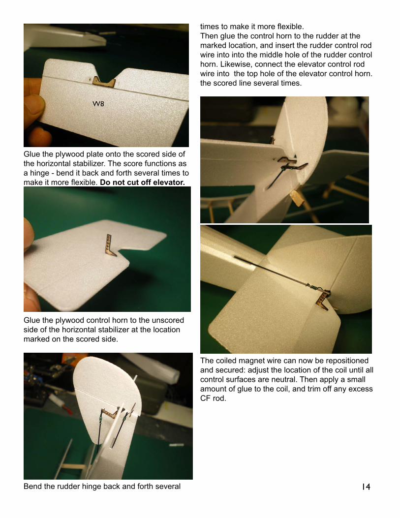
Glue the plywood plate onto the scored side of the horizontal stabilizer. The score functions as a hinge - bend it back and forth several times to make it more flexible. Do not cut off elevator.
Glue the plywood control horn to the unscored side of the horizontal stabilizer at the location marked on the scored side.
Bend the rudder hinge back and forth several
times to make it more flexible.Then glue the control horn to the rudder at the marked location, and insert the rudder control rod wire into into the middle hole of the rudder control horn. Likewise, connect the elevator control rod wire into the top hole of the elevator control horn.the scored line several times.
The coiled magnet wire can now be repositioned and secured: adjust the location of the coil until all control surfaces are neutral. Then apply a small amount of glue to the coil, and trim off any excess CF rod.
14

Mounting The Motor
Cut gearbox mounting tabs as shown using diagonal cutters. This will set the down thrust angle.
Glue motor mounting assembly as shown. ‘Top L’ goes to Top left, ‘Top R’ placed top right and so on.
With the gear box properly mounted, the motor
shaft will be angled right when viewed from the top, and down when viewed from the side.
Assembling The Cowl
Glue the cowl pieces on top of each other in the sequence shown - left to right.
Properly assembled cowl
Roll the cowl side strip(W15) around a cylinder such as a pen or brush. Roll both end of strip. 15

Glue cowl side strip to the back of the cowl front assembly.
Sand edges smooth.
Making The Wheels
Glue a small and large round balsa disc to each side of the foam wheels. Then slide a 10mm aluminum tubing bushing through the wheel
center hole, with one side protruding 1mm beyond the smaller balsa disc. Apply CA glue on longer side of bushing.
Glue the edges of each wheel cover together to form two cone shapes.
Completed wheels
Center a 95mm CF rod between the wheel struts. Using thread, tie the rods together in the middle, and set with a dab of CA glue.
16

Building The Vickers Machine Gun
Roll machine gun barrel around a thin rod such as tooth pick. Scored side must be at the outside of barrel, creating ribbed surface.
Glue two round disc parts onto each end of the barrel, and attach it to the body. Refer to completed pictures for location of the machine gun.
Installing Tail Skid
Mount wheels and wheel retainers. Apply only a small amount of glue to the outside of the aluminum wheel retainers, making sure the wheels rotate freely.
Installing bottom covers
First glue tail side depron bottom cover (W16)
Battery compartment/ under carriage will be next. Before gluing on the bottom cover, make sure the motor rotates the gear shaft in the correct direction (counter clockwise when viewed from the front).
Glue the battery compartment/undercarriage assembly to the fuselage. Six dots of glue at the edge will do the job.
Since you may need to pull this assembly out of the fuselage for maintenance (such as changingthe motor or replacing the receiver), I recommend using the minimum amount of foam glue when securing the battery compartment/undercarriage. 17

Fabricating The Engine Cover
Roll a round object over the back of the engine cover several times to make this plate as thin as possible.
Sand the plate’s edges and glue onto the fuselage as shown.
Installing The Cockpit Coaming
Glue cockpit coaming (W17) around the opening as shown.
Installing the propeller
Using household scissors or another appropriate tool, trim 8mm off each blade, making the propeller 114mm.
It is not easy to screw a propeller onto the shaft when there is no good way to grab the shaft. Even with hemomostat, it won’t be possible to turn the propeller 360 degree while grabbing shaft. If you have your own way of screwing propeller to the shaft, please igonore following process.
The process described here may sound complicated. In short, I am describing the screwing propeller in repetition of 1/6 turns.
If you need to remove propeller, see next photo. Again repeat motion 1 & 2
18

Checking wing alignment
Holding your triplane in one hand, look at the airplane from the front. Left and right must be reasonably symmetrical.
If your wing is twisted...
Don’t Panic. First try straighten the wings by bending the wing surfaces. If repostioning the ribs are necessary, break off the bond between rib and struts using hobby knife. Twisted wings tend to make an airplane favored to one side, requiring significant amount of trim.
Inserting battery
Before maiden your Triplane
Using your transmitter, you will need to reverse the travel of each servo . Refer to your transmitter manual.
Check your control surface for proper deflection: when you pull back the elevator stick, the elevator should deflect up; when you move the aileron stick to the right, the rudder should deflect to the right when looked at from behind.
If using 160mah batteries, the model should balance at the score line just in front of the middle wing spar. If using lighter batteries, you may need to add weight to the nose.
With the P-51 motor (black end bell 8.5mm motor), 35% throttle will maintain level flight.
Power off landing is possible, but I recommend little bit of power (20%) on final approach to keep the nose up. Remember that biplanes and triplanes slow down faster because of the drag of the extra wings.
Most mid-level RC flyers will be able to handle my Sopwith Triplane with no problems. At first most RC flyers find controls very sensitive and responsive but get accustomed to the control in less than two circles. However, I strongly recommend flying over grass in calm weather for your maiden flight.
ENJOY!
Jinwoo ChoeJuly 2011
Special thanks to:Paul ‘Newbeflyer’ for beta testing the kit.Gene ‘Speedy01’ for proofreading this manual.(all mistakes you will see in this manual are made after Gene’s initial corrections)All RCgroups.com members for support and encouragements.My wife, Julia for endless smiles Thank You. 19

20

21

22