Embed Size (px)
Citation preview

Ultra Low Power Microcontroller- Design Criteria -
June 2017
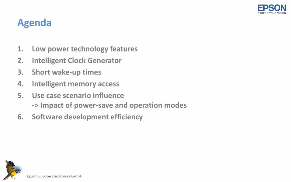
Agenda
1. Low power technology features2. Intelligent Clock Generator3. Short wake-up times4. Intelligent memory access5. Use case scenario influence
-> Impact of power-save and operation modes6. Software development efficiency
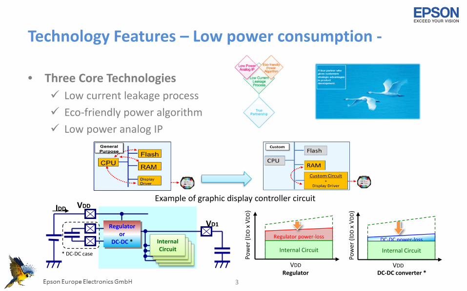
Technology Features – Low power consumption -
• Three Core Technologies Low current leakage process Eco-friendly power algorithm Low power analog IP
3
VDD
Pow
er (I
DDx
VDD)
Regulator power-loss
Internal Circuit
RegulatorVDD
Pow
er (I
DDx
VDD)
DC-DC power-loss
DC-DC converter *
Internal Circuit
VDD
Regulatoror
DC-DC *
VD1
IDD
InternalCircuit
* DC-DC case
Example of graphic display controller circuit
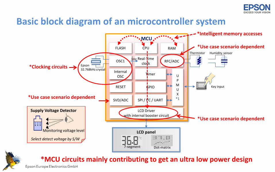
Basic block diagram of an microcontroller system MCU
CPUFLASH
RESET
Real-Timeclock
GPIO
Thermistor
Epson 32.768kHz crystal
OSC1 RFC/ADC
RAM
UPMUX
*1SPI / I²C / UART
Timer
1Hz
LCD Driverwith internal booster circuit
Humidity sensor
LCD panel
SVD/ADC
InternalOSC
Key input
7-segment Dot-matrix
*Clocking circuits
*Use case scenario dependent
*Use case scenario dependentSupply Voltage Detector
Monitoring voltage level
Select detect voltage by S/W
*Use case scenario dependent
*MCU circuits mainly contributing to get an ultra low power design
*Intelligent memory accesses
Intelligent clock generator (1)
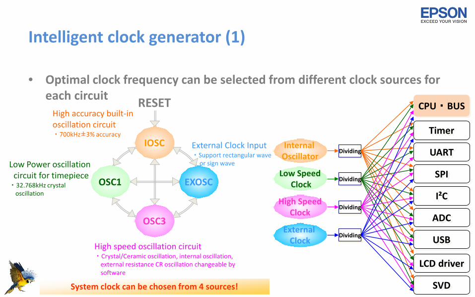
• Optimal clock frequency can be selected from different clock sources foreach circuit
5
High accuracy built-in oscillation circuit・700kHz±3% accuracy
OSC1
OSC3
IOSC
EXOSC
RESET
Low Power oscillation circuit for timepiece
・32.768kHz crystaloscillation
High speed oscillation circuit・Crystal/Ceramic oscillation, internal oscillation,
external resistance CR oscillation changeable bysoftware
External Clock Input・Support rectangular wave
or sign wave
System clock can be chosen from 4 sources!
Timer
UART
SPI
LCD driver
SVD
ADC
USB
I²C
CPU・BUS
Low SpeedClock
High SpeedClock
Internal Oscillator
External Clock
Dividing
Dividing
Dividing
Dividing
Intelligent clock generator (2)
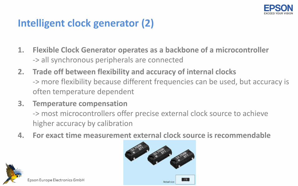
1. Flexible Clock Generator operates as a backbone of a microcontroller-> all synchronous peripherals are connected
2. Trade off between flexibility and accuracy of internal clocks-> more flexibility because different frequencies can be used, but accuracy isoften temperature dependent
3. Temperature compensation-> most microcontrollers offer precise external clock source to achievehigher accuracy by calibration
4. For exact time measurement external clock source is recommendable
Short wake-up times
Low Speed Clock
High Speed ClockSystem CLK(CPU, BUS, Memory)
RTC/LCD DriverCLK
High Speed Clock
SLEEP Port or RTC/LCD interrupt
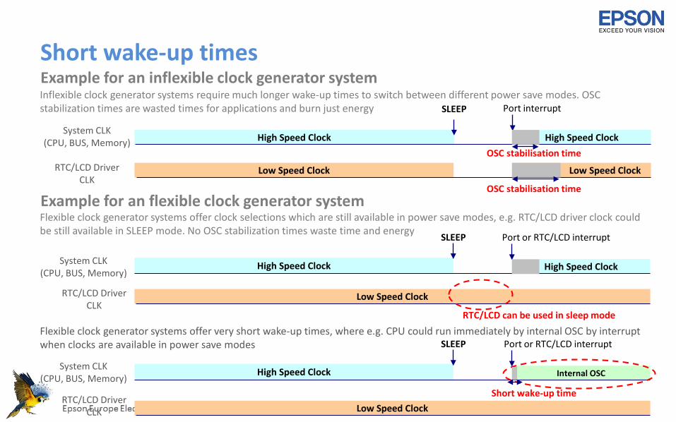
Example for an flexible clock generator system
Low Speed Clock
High Speed ClockSystem CLK
(CPU, BUS, Memory)
RTC/LCD DriverCLK
Low Speed Clock
High Speed Clock
SLEEP
Example for an inflexible clock generator system
Low Speed Clock
High Speed ClockSystem CLK(CPU, BUS, Memory)
RTC/LCD DriverCLK
Internal OSC
SLEEP
Inflexible clock generator systems require much longer wake-up times to switch between different power save modes. OSC stabilization times are wasted times for applications and burn just energy
Flexible clock generator systems offer clock selections which are still available in power save modes, e.g. RTC/LCD driver clock could be still available in SLEEP mode. No OSC stabilization times waste time and energy
Flexible clock generator systems offer very short wake-up times, where e.g. CPU could run immediately by internal OSC by interrupt when clocks are available in power save modes Port or RTC/LCD interrupt
Port interrupt
OSC stabilisation time
Short wake-up time
RTC/LCD can be used in sleep mode
OSC stabilisation time

Intelligent memory access
• Standard system:CPU read out / write display data tomemory-> Result: high CPU workload and
high power consumption
• Intelligent system:Only „Custom circuit“ is handling displaydata -> no CPU workload and no flashmemory involvement-> Result: much lower power consumption
8
RAM
Flash
CPU
Display Driver
RAM
Flash
CPUCustom Circuit + Display Driver
Example: Improvement of display performance
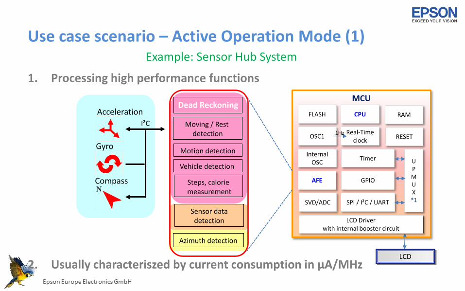
Use case scenario – Active Operation Mode (1)
1. Processing high performance functions
2. Usually characteriszed by current consumption in µA/MHz
AccelerationMoving / Rest
detection
Vehicle detection
Steps, caloriemeasurement
I²C
Gyro
CompassN
Dead Reckoning
Azimuth detection
Sensor datadetection
Motion detection
MCU
CPUFLASH
RESETReal-Time
clock
GPIO
OSC1
AFE
RAM
UPMUX
*1SPI / I²C / UART
Timer
1Hz
LCD Driverwith internal booster circuit
SVD/ADC
InternalOSC
LCD
Example: Sensor Hub System
Use case scenario – Active Operation Mode (2)
Coremark value:In ULP (Ultra Low Power) designs „µA/MHz“ has only limited relevance, becauseprocessing power must be considered too to get total overview-> therefore Coremark is a useful indication about MCU performance
Example:An 16-bit MCU achieves a benchmark value of 0.6 Coremark/MHz while an 32-bit MCU achieves 2.9 Coremark/MHz-> 32-bit processor can execute same task five times faster than 16-bit processor-> total power consumption is reduced if MCU active time is short!-> Result: An intelligent processor core architecture, in this case a 32-bit MCU could be
more energy efficient than a 16-bit MCU
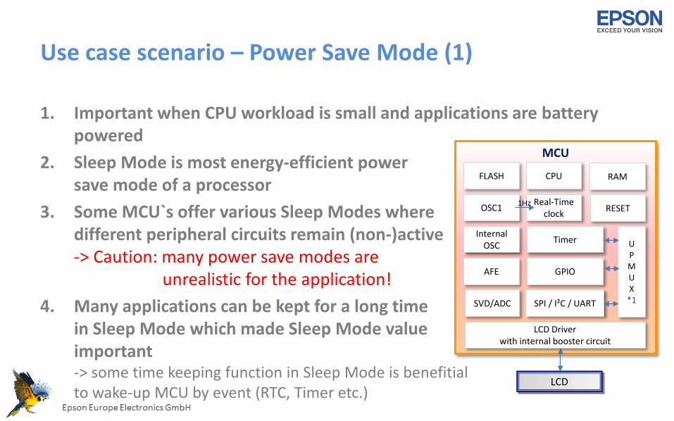
Use case scenario – Power Save Mode (1)
1. Important when CPU workload is small and applications are batterypowered
2. Sleep Mode is most energy-efficient powersave mode of a processor
3. Some MCU`s offer various Sleep Modes wheredifferent peripheral circuits remain (non-)active-> Caution: many power save modes are
unrealistic for the application!4. Many applications can be kept for a long time
in Sleep Mode which made Sleep Mode valueimportant-> some time keeping function in Sleep Mode is benefitialto wake-up MCU by event (RTC, Timer etc.)
MCU
CPUFLASH
RESETReal-Time
clock
GPIO
OSC1
AFE
RAM
UPMUX
*1SPI / I²C / UART
Timer
1Hz
LCD Driverwith internal booster circuit
SVD/ADC
InternalOSC
LCD

Use case scenario – Power Save Mode (2)
1. Supply voltage conditions have big influence on MCU operation conditionsand some energy –efficient power save modes
2. MCU`s operating below 1.8V could bring some benefits3. Integrated DC/DC converter technology can be key to achieve attractive
power consumption values-> e.g. Sleep Mode: 32-bit ARM Cortex M0+: 800nA or 16-bit MCU: 150nA-> e.g. Run Mode: 16-bit MCU only 4µA in active mode still driving a LCD
VDD
Pow
er (I
DDx
VDD)
Regulator power-loss
Internal Circuit
RegulatorVDD
Pow
er (I
DDx
VDD)
DC-DC power-loss
DC-DC converter *
Internal Circuit
VDD
Regulatoror
DC-DC *
VD1
IDD
InternalCircuit
* DC-DC case
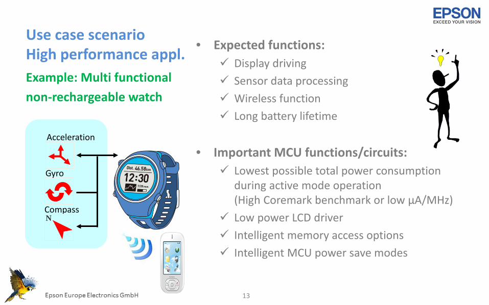
Use case scenarioHigh performance appl. • Expected functions:
Display driving Sensor data processing Wireless function Long battery lifetime
• Important MCU functions/circuits: Lowest possible total power consumption
during active mode operation(High Coremark benchmark or low µA/MHz)
Low power LCD driver Intelligent memory access options Intelligent MCU power save modes
Example: Multi functionalnon-rechargeable watch
13
Acceleration
Gyro
CompassN
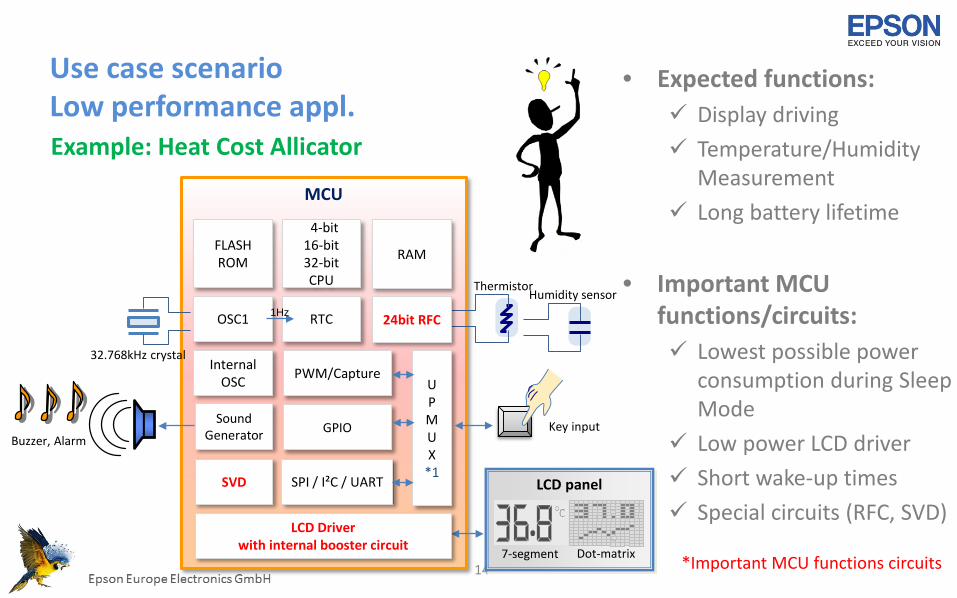
Use case scenarioLow performance appl.
• Expected functions: Display driving Temperature/Humidity
Measurement Long battery lifetime
• Important MCU functions/circuits: Lowest possible power
consumption during SleepMode
Low power LCD driver Short wake-up times Special circuits (RFC, SVD)
Example: Heat Cost Allicator
14
MCU
4-bit16-bit32-bit CPU
FLASHROM
SoundGenerator
RTC
GPIO
Thermistor
32.768kHz crystal
OSC1 24bit RFC
RAM
UPMUX
*1SPI / I²C / UART
PWM/Capture
1Hz
LCD Driverwith internal booster circuit
Humidity sensor
LCD panelSVD
InternalOSC
Key input
7-segment Dot-matrix
Buzzer, Alarm
*Important MCU functions circuits
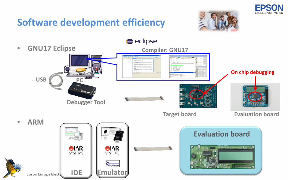
Software development efficiency
• GNU17 Eclipse
• ARM
PC
Compiler: GNU17
USB
Debugger Tool
Target board Evaluation board
On chip debugging
IDE Emulator
Evaluation board

LCD panel
7-segment Dot-matrix
S1C17W18RAM8KB
FLASH128KB
OSC3Cera / Int.
SVD
SoundGen.
RTC
LCD Driver48 x 4/44 x 8
GPIO
3.6V
Pi
32.768kHz
OSC1
Temp. sensor / Ref. voltage gen.
12bit ADC
RFC SPI / I²C /UART
1Hz
VREFA
ThermistorHumidity UPMUX
S1C31W74
RAM128KB
FLASH512KB
OSC3Cera / Int.
SVD
SoundGen.
RTC
LCD Driver (1/5 or 1/4B)72x32 / 80x24 / 88x16 GPIO
3.6V
Pi
32.768kHzOSC1
X`tal/Int. IOSC
QSPISPI / I²C /UART
1Hz
USBDeviceDMA
Flash
CASH ARM ® Cortex ® -M0+