Embed Size (px)
Citation preview
MSP430FR6989
eZ-FET withenergytracing
USB HIDcommunication
bridge
160-segmentLCD
TMRsensor
RFconnector
ES
I
USB
EVM430-FR6989Main Board
TMR SensorBoard
Buttons andLEDs
ESICI0
ESICI1
ESICOM
sin
cos
GND
ESIVCC VCC
1TIDUA14A–June 2015–Revised July 2016Submit Documentation Feedback
Copyright © 2015–2016, Texas Instruments Incorporated
Ultra-Low-Power Flow Meter Using TMR Sensors Reference Design forExtended System Longevity
TI DesignsUltra-Low-Power Flow Meter Using TMR SensorsReference Design for Extended System Longevity
All trademarks are the property of their respective owners.
TI DesignsTI Designs provide the foundation that you needincluding methodology, testing and design files toquickly evaluate and customize the system. TI Designshelp you accelerate your time to market.
Design Resources
TIDM-TMR-WATERMTR Design FolderMSP430FR6989 Product FolderEVM430-FR6989 Tools Folder
ASK Our E2E ExpertsWEBENCH® Calculator Tools
Design Features• Daughter TMR Sensor Board for EVM430-FR6989• Rotation Detection Using TMR Sensors• Example for Calibration• Ultra-Low Power to Use With ESI
Featured Applications• Flow Meter• Gas Meter• Heat Meter• Rotation Detection
An IMPORTANT NOTICE at the end of this TI reference design addresses authorized use, intellectual property matters and otherimportant disclaimers and information.

TMR Sensor
S
Split pole magnet
N
Signal output
1.5
1.6
1.7
1.8
50 100 150 200 250 300 350 400 450 500 550 600 650 700
System Description www.ti.com
2 TIDUA14A–June 2015–Revised July 2016Submit Documentation Feedback
Copyright © 2015–2016, Texas Instruments Incorporated
Ultra-Low-Power Flow Meter Using TMR Sensors Reference Design forExtended System Longevity
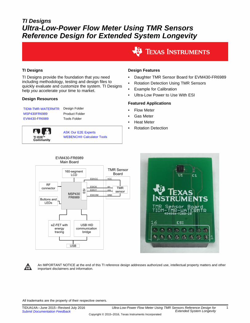
1 System DescriptionWhen designing battery-powered applications, ultra-low power consumption is the key factor in extendingthe lifetime of a system. Long-running designs must not waste the energy they are provided. This TIdesign highlights the usage of TMR sensor and Extended Scan Interface (ESI) to archive ultra-low powerrotation detection for flow meter application. The evaluation kit EVM430-FR6989 is used for this test.
1.1 MSP430FR6989The MSP430FR6989 is an MSP430™ ultra-low-power FRAM platform that combines a uniquelyembedded FRAM and a holistic ultra-low-power system architecture, allowing innovators to increaseperformance at lowered energy budgets. FRAM technology combines the speed, flexibility, and enduranceof SRAM with the stability and reliability of flash at a much lower power.
1.1.1 ESIThe built-in ESI module measures linear or rotational motion automatically with the lowest possible powerconsumption. The ESI consists of two analog front ends and several processing units. The analog frontend stimulates the sensors, senses the signal levels, and converts them into their digital representation.The processing units analyze the signals and count rotation or motion. The MCU is not involved for themeasurement process and stays in sleep mode. Therefore, the system current can be kept as low aspossible.
1.2 TMR SensorTunnel magnetoresistance (TMR) is a magnetoresistive effect that occurs in a magnetic tunnel junction(MTJ) that consists of two ferromagnets separated by a thin insulating film. The electrons that passthrough the insulating film depend on the direction of the magnetizations of those two ferromagnets. Suchphenomenon can be translated into electrical resistance that is favorable for measuring magnetic fielddirection using microcontrollers.
Figure 1. TMR Sensor

www.ti.com System Description
3TIDUA14A–June 2015–Revised July 2016Submit Documentation Feedback
Copyright © 2015–2016, Texas Instruments Incorporated
Ultra-Low-Power Flow Meter Using TMR Sensors Reference Design forExtended System Longevity
1.3 EVM430-FR6989The EVM430-FR6989 evaluation kit is used to get the test result for this TI Design. This water meterreference design kit is an easy-to-use evaluation module for the MSP430FR698x family ofmicrocontrollers. The kit consists of three boards: the main board, the sensor board, and the motor board.
The main board of the EVM consists of the MSP430FR6989 with different user interfaces such as LCD,buttons, and LEDs. The built-in eZ-FET enables direct programing to the MCU without extra FET tools.The eZ-FET also supports EnergyTrace™ technology to monitor power consumption of the system. TheMSP430FR6989 also supports EnergyTrace++™ to monitor the usage of different modules inside theMCU.
Designed for flow meter applications, the sensor board is a daughter board consisting of two LC sensors.The sensors are connected to the ESI module of the MSP430FR6989. Designers can design their ownsensor boards for any specific applications that use ESI. In this TI Design, this LC board is not used andreplaced by the TMR sensor board.
The motor board drives the rotor disc to simulate water or gas flow. The buttons control the rotatingdirection of the disc while the variable resistor controls the rotating speed. Visit the device's product pagefor a detailed description.
Figure 2. EVM430-FR6989 Evaluation Kit

MSP430FR6989
eZ-FET withenergytracing
USB HIDcommunication
bridge
160-segmentLCD
TMRsensor
RFconnector
ES
I
USB
EVM430-FR6989Main Board
TMR SensorBoard
Buttons andLEDs
ESICI0
ESICI1
ESICOM
sin
cos
GND
ESIVCC VCC
System Design Theory www.ti.com
4 TIDUA14A–June 2015–Revised July 2016Submit Documentation Feedback
Copyright © 2015–2016, Texas Instruments Incorporated
Ultra-Low-Power Flow Meter Using TMR Sensors Reference Design forExtended System Longevity
2 System Design TheoryBecause the analog frontend of the ESI provides most of the components for measurement, the hardwareconfiguration of the external sensor circuit is simple. The outputs of the TMR sensor is connected to thecomparator inputs of the ESI, while the supply voltage of the TMR sensor is connected to ESIDVCC thatis also connected to DVCC of the MCU. The GND of the TMR sensor is connected to the ESICOM insteadof the system GND. This connection lowers the system current as described in Section 2.2.
Figure 3. Block Diagram
Sine output
Cosine output
Reference voltagewith hysteresis
1
1
1 1 1
1 1 10 0
0 0
00
0 0
Digitized Output
Volt
Angle
1.5
1.6
1.7
1.8
50 100 150 200 250 300 350 400 450 500 550 600 650 700
www.ti.com System Design Theory
5TIDUA14A–June 2015–Revised July 2016Submit Documentation Feedback
Copyright © 2015–2016, Texas Instruments Incorporated
Ultra-Low-Power Flow Meter Using TMR Sensors Reference Design forExtended System Longevity
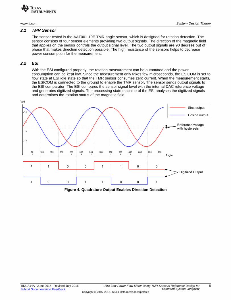
2.1 TMR SensorThe sensor tested is the AAT001-10E TMR angle sensor, which is designed for rotation detection. Thesensor consists of four sensor elements providing two output signals. The direction of the magnetic fieldthat applies on the sensor controls the output signal level. The two output signals are 90 degrees out ofphase that makes direction detection possible. The high resistance of the sensors helps to decreasepower consumption for the measurement.
2.2 ESIWith the ESI configured properly, the rotation measurement can be automated and the powerconsumption can be kept low. Since the measurement only takes few microseconds, the ESICOM is set toflow state at ESI idle state so that the TMR sensor consumes zero current. When the measurement starts,the ESICOM is connected to the ground to enable the TMR sensor. The sensor sends output signals tothe ESI comparator. The ESI compares the sensor signal level with the internal DAC reference voltageand generates digitized signals. The processing state machine of the ESI analyses the digitized signalsand determines the rotation status of the magnetic field.
Figure 4. Quadrature Output Enables Direction Detection

Start
Initialization
Calibration
Low power
mode
Enable interrupts
ESIinterrupt
triggered?
Update LCD
Y
NButton
pressed?
Toggle LCD,
increase sampling rate, or
decrease sampling rate
Y
N
Software Description www.ti.com
6 TIDUA14A–June 2015–Revised July 2016Submit Documentation Feedback
Copyright © 2015–2016, Texas Instruments Incorporated
Ultra-Low-Power Flow Meter Using TMR Sensors Reference Design forExtended System Longevity
3 Software DescriptionThe software setup is also kept simple to minimize power consumption. When the system starts, thehardware modules, such as the clock system and the ESI, are initialized. Then, the calibration starts tofind the suitable reference voltage for rotation detection. The calibration requires the magnet to rotate tofind the maximum and minimum output voltage of the TMR sensor. After the calibration completes, theESI interrupts are set up. The system then goes to a low-power mode. The system wakes up when thenavigation button is pressed or the ESI interrupts are triggered to update the LCD. The upper part of theLCD shows the sampling rate of the ESI measurement while the lower part shows the ESI counternumber. If the navigation button is pressed upward, the sampling rate of the measurement increases. If itis pressed downward, the sampling rate of the measurement decreases. The LCD is toggles if the centeris pressed. The LCD shows the sampling rate for 1 second if the LCD is toggled off.
Figure 5. Software Flow

LCD
Sensor
board
connecto
r
PO
RT
_9/E
SIRF2
RF1 MCU
USB
MCURESET
COMMReset
BUT
JP14
JP13
LED2
LED1
OscillatorCircuit
LCDCircuit
PO
RT
_6_
8P
OR
T_
1_
4P
OR
T_
2_
3
PORT_J
7 5 3 18 6 4 2
1 23 45 67 8
1 23 45 67 8
1 23 45 67 8
COMMBSL
2 4 6 8
1 3 5 7
2 4 6
1 3 5
2 4 6 8
1 3 5 7
TE
ST
_S
BW
RS
T_
SB
WE
Z_
RX
DE
Z_
TX
D
GN
DE
ZF
ET
_V
CC
3V
3
CO
MM
_R
XC
OM
M_
TX
CO
MM
_R
DY
_O
UT
CO
MM
_R
DY
_IN
IsolationIsolation
12
34
56
7
1 2 3 4 5 6 7
COMMMCU
LE
D3
LE
D2
LE
D1
LE
D0
EZ-fet
USBHub
PowerCircuit
1 2 3 4 3 2 1Debug Circuit
EZ
-fet
LE
D
MC
US
BW
EZ
-fet
JTA
G
COMM JTAG
J600J201J601J401J102
GG
G
Jumper
www.ti.com Test Setup
7TIDUA14A–June 2015–Revised July 2016Submit Documentation Feedback
Copyright © 2015–2016, Texas Instruments Incorporated
Ultra-Low-Power Flow Meter Using TMR Sensors Reference Design forExtended System Longevity
4 Test SetupThe following steps show the testing procedure using the EVM430-FR6989 and Code Composer Studio™(CCS) version 6.1.1. Prepare
(a) Connect the jumpers of the EVM430-FR6989 main board as shown in Figure 6.
Figure 6. Jumper Setting of Main Board
(b) Attach the TMR sensor board to the ESI port of the EVM430-FR6989 main board.(c) Connect the EVM430-FR6989 main board to the PC with an USB cable.

Test Setup www.ti.com
8 TIDUA14A–June 2015–Revised July 2016Submit Documentation Feedback
Copyright © 2015–2016, Texas Instruments Incorporated
Ultra-Low-Power Flow Meter Using TMR Sensors Reference Design forExtended System Longevity
(d) Glue the split pole magnet on the PCB disc of the motor board of the EVM430-FR6989.
Figure 7. Glue Split Pole Magnet
(e) Place the motor board that the magnet is about 5 mm away from the TMR sensor.(f) Switch on the motor board.
2. Start the test(a) Launch CCS and load the test project.(b) Start the debug session of the CCS.(c) During calibration, the "8888" is shown on the LCD of the main board.(d) Start rotating the magnet by pressing the BUT1 or BUT2 of the motor board.(e) After the calibration is completed, the counter number of the ESI is shown on the LCD.(f) Press center of the navigation button to toggle off the LCD.
3. During the test(a) Press up or down of the navigation button to change the sampling rate of the measurement.(b) Pause the debug session of the CCS.(c) Start free run mode (Menu → Run → Free Run).(d) Observe power consumption with the energy trace function of CCS.(e) The total energy consumption and the voltage are recorded for calculating the test results.
4. Repeat Step 3 to test different sampling rates.

0
2
4
6
8
10
12
14
16
0 1000 2000 3000 4000 5000 6000
Cu
rre
nt
(µA
)
Samples per second
Current consumption Energy (mJ) 10 s 3.27 V= ¸ ¸
www.ti.com Test Data
9TIDUA14A–June 2015–Revised July 2016Submit Documentation Feedback
Copyright © 2015–2016, Texas Instruments Incorporated
Ultra-Low-Power Flow Meter Using TMR Sensors Reference Design forExtended System Longevity
5 Test DataThe following shows the test result at different sampling rates. The total energy is obtained by running infree run mode for 10 seconds. The test voltage was measured at 3.27 V. The current is calculated by thefollowing equation.
(1)
Table 1. Measuring Result
SAMPLES PER SECOND ENERGY (mJ) CURRENT (µA)99 0.032 0.98202 0.041 1.25298 0.049 1.5420 0.059 1.8496 0.065 1.99607 0.074 2.26780 0.089 2.721092 0.115 3.521260 0.13 3.971489 0.15 4.591820 0.178 5.442340 0.222 6.793277 0.299 9.145461 0.47 14.37
Figure 8. Power Consumption versus Sampling Rate

Design Files www.ti.com
10 TIDUA14A–June 2015–Revised July 2016Submit Documentation Feedback
Copyright © 2015–2016, Texas Instruments Incorporated
Ultra-Low-Power Flow Meter Using TMR Sensors Reference Design forExtended System Longevity
6 Design Files
6.1 SchematicsTo download the schematics, see the design files at TIDM-TMR-WATERMTR.
Figure 9. TIDM-TMR-WATERMTR Schematic

www.ti.com Design Files
11TIDUA14A–June 2015–Revised July 2016Submit Documentation Feedback
Copyright © 2015–2016, Texas Instruments Incorporated
Ultra-Low-Power Flow Meter Using TMR Sensors Reference Design forExtended System Longevity
6.2 Bill of MaterialsTo download the bill of materials (BOM), see the design files at TIDM-TMR-WATERMTR.
6.3 Layer PlotsTo download the layer plots, see the design files at TIDM-TMR-WATERMTR.
6.4 Eagle Design ProjectTo download the Altium project files, see the design files at TIDM-TMR-WATERMTR.
6.5 Gerber FilesTo download the Gerber files, see the design files at TIDM-TMR-WATERMTR.
7 Software FilesTo download the software files, see the design files at TIDM-TMR-WATERMTR.
8 References
1. Wikipedia, Tunnel magnetoresistance (http://en.wikipedia.org/wiki/Tunnel_magnetoresistance).
9 About the AuthorZACK MAK is a system application engineer at Texas Instruments where he is responsible for developingreference design solutions for the industrial segment. Zack earned his bachelor of electronic andcommunication engineering from the City University of Hong Kong.

Revision History www.ti.com
12 TIDUA14A–June 2015–Revised July 2016Submit Documentation Feedback
Copyright © 2015–2016, Texas Instruments Incorporated
Revision History
Revision HistoryNOTE: Page numbers for previous revisions may differ from page numbers in the current version.
Changes from Original (June 2015) to A Revision ......................................................................................................... Page
• Changed title from Low-Power Flow Meter Design Using TMR Sensors to Ultra-Low-Power Flow Meter Using TMRSensors Reference Design for Extended System Longevity ........................................................................ 1

IMPORTANT NOTICE FOR TI REFERENCE DESIGNS
Texas Instruments Incorporated (‘TI”) reference designs are solely intended to assist designers (“Designer(s)”) who are developing systemsthat incorporate TI products. TI has not conducted any testing other than that specifically described in the published documentation for aparticular reference design.TI’s provision of reference designs and any other technical, applications or design advice, quality characterization, reliability data or otherinformation or services does not expand or otherwise alter TI’s applicable published warranties or warranty disclaimers for TI products, andno additional obligations or liabilities arise from TI providing such reference designs or other items.TI reserves the right to make corrections, enhancements, improvements and other changes to its reference designs and other items.Designer understands and agrees that Designer remains responsible for using its independent analysis, evaluation and judgment indesigning Designer’s systems and products, and has full and exclusive responsibility to assure the safety of its products and compliance ofits products (and of all TI products used in or for such Designer’s products) with all applicable regulations, laws and other applicablerequirements. Designer represents that, with respect to its applications, it has all the necessary expertise to create and implementsafeguards that (1) anticipate dangerous consequences of failures, (2) monitor failures and their consequences, and (3) lessen thelikelihood of failures that might cause harm and take appropriate actions. Designer agrees that prior to using or distributing any systemsthat include TI products, Designer will thoroughly test such systems and the functionality of such TI products as used in such systems.Designer may not use any TI products in life-critical medical equipment unless authorized officers of the parties have executed a specialcontract specifically governing such use. Life-critical medical equipment is medical equipment where failure of such equipment would causeserious bodily injury or death (e.g., life support, pacemakers, defibrillators, heart pumps, neurostimulators, and implantables). Suchequipment includes, without limitation, all medical devices identified by the U.S. Food and Drug Administration as Class III devices andequivalent classifications outside the U.S.Designers are authorized to use, copy and modify any individual TI reference design only in connection with the development of endproducts that include the TI product(s) identified in that reference design. HOWEVER, NO OTHER LICENSE, EXPRESS OR IMPLIED, BYESTOPPEL OR OTHERWISE TO ANY OTHER TI INTELLECTUAL PROPERTY RIGHT, AND NO LICENSE TO ANY TECHNOLOGY ORINTELLECTUAL PROPERTY RIGHT OF TI OR ANY THIRD PARTY IS GRANTED HEREIN, including but not limited to any patent right,copyright, mask work right, or other intellectual property right relating to any combination, machine, or process in which TI products orservices are used. Information published by TI regarding third-party products or services does not constitute a license to use such productsor services, or a warranty or endorsement thereof. Use of the reference design or other items described above may require a license from athird party under the patents or other intellectual property of the third party, or a license from TI under the patents or other intellectualproperty of TI.TI REFERENCE DESIGNS AND OTHER ITEMS DESCRIBED ABOVE ARE PROVIDED “AS IS” AND WITH ALL FAULTS. TI DISCLAIMSALL OTHER WARRANTIES OR REPRESENTATIONS, EXPRESS OR IMPLIED, REGARDING THE REFERENCE DESIGNS OR USE OFTHE REFERENCE DESIGNS, INCLUDING BUT NOT LIMITED TO ACCURACY OR COMPLETENESS, TITLE, ANY EPIDEMIC FAILUREWARRANTY AND ANY IMPLIED WARRANTIES OF MERCHANTABILITY, FITNESS FOR A PARTICULAR PURPOSE, AND NON-INFRINGEMENT OF ANY THIRD PARTY INTELLECTUAL PROPERTY RIGHTS.TI SHALL NOT BE LIABLE FOR AND SHALL NOT DEFEND OR INDEMNIFY DESIGNERS AGAINST ANY CLAIM, INCLUDING BUT NOTLIMITED TO ANY INFRINGEMENT CLAIM THAT RELATES TO OR IS BASED ON ANY COMBINATION OF PRODUCTS ASDESCRIBED IN A TI REFERENCE DESIGN OR OTHERWISE. IN NO EVENT SHALL TI BE LIABLE FOR ANY ACTUAL, DIRECT,SPECIAL, COLLATERAL, INDIRECT, PUNITIVE, INCIDENTAL, CONSEQUENTIAL OR EXEMPLARY DAMAGES IN CONNECTION WITHOR ARISING OUT OF THE REFERENCE DESIGNS OR USE OF THE REFERENCE DESIGNS, AND REGARDLESS OF WHETHER TIHAS BEEN ADVISED OF THE POSSIBILITY OF SUCH DAMAGES.TI’s standard terms of sale for semiconductor products (http://www.ti.com/sc/docs/stdterms.htm) apply to the sale of packaged integratedcircuit products. Additional terms may apply to the use or sale of other types of TI products and services.Designer will fully indemnify TI and its representatives against any damages, costs, losses, and/or liabilities arising out of Designer’s non-compliance with the terms and provisions of this Notice.IMPORTANT NOTICE
Mailing Address: Texas Instruments, Post Office Box 655303, Dallas, Texas 75265Copyright © 2016, Texas Instruments Incorporated