Embed Size (px)
Citation preview
( )9
Ultra-Low Platform Cart System
Toshiyuki Ueno, Yasuchika Nakayama, Tsuyoshi Yamada, Koji Shibata
Automatic guided vehicle, Cart, Ultra-low-platform
1. Preface Since our first release of the Automated Guided
Vehicle (AGV) in 1983, we developed the ACB Seriesin 1987 which is the standard truck series; and then in2000, the 2ACB Series capable of omni-directionalmaneuvering was developed. These products met theneeds of our customers in the work of handling materi-als.
Recently at the manufacturing sites, there arerequests from customers who want to build their ownmaterial handling systems in order to realize the effi-cient material-moving systems by incremental dailyimprovements. To meet such demands, we developedan affordable, flexible, easy-to-use, and simple AGVunit called“MCAT”and released it in 2005. If thisMCAT is put under any wheeled cart designed andmanufactured by a customer, it can convert to an auto-mated guided cart as the AGV.
This paper introduces the newly developed U-CART, the ultra-low-platform cart system, which is anapplied product of MCAT. It can go under any commer-cial basket cart or an existing customer’s cart; and withthe electric up-and-down catch pin, it can make thecoupling of basket cart automatically and can move thecart.
When this U-CART is in use, other carts availableon market can be converted to the AGVs with minimalmodification. In addition, a single U-CART can pull andmove multiple carts.
2. Major Specifications U-CART introduced here is an AGV that follows a
guide path taped on the floor. There are two types: U-CART S and U-CART L. U-CART S is equipped with adrive unit and can move forward and backward in asimple manner. U-CART L is equipped with double-drive units and it can move in every direction includingtraversing. Each model has high-speed type and low-speed type. A total of four types are available. Fig. 1shows an external appearance of U-CART L.
The front side of U-CART is equipped with a non-contact obstacle detector to avoid collision and abumper. This part of U-CART is also equipped with apower switch, a manual operator switch for a catch pin,and a signal receiver of an optical remote controller.
Abstract We developed an ultra-low-platform Automated Guided Vehicle (AGV) called“U-CART.”It can go under a
commercial basket cart and with the electric up-and-down catch pin, it can make the coupling with a basket cart andcarry the cart. There are two types: U-CART S and U-CART L. U-CART S offers forward and simplified reversemaneuvering. U-CART L uses two drive units and offers forward/reverse moving, traversing, and spin-turns. Bothmodels demonstrate the most compact and low-platform level in the Japanese AGV industry. The body heightmeasures (170mm) and the vehicle width (348mm), therefore, U-CART can go under any basket cart available in themarket without changing the cart’s platform height level and can convert to AGV with minimum modifications. It alsocomes with high power as it can pull the cart at maximum 1300kg. Further, with simple system configuration, stopscan be arranged at a maximum of 200 stations and a maximum 200 crossing points.
〈Transportation〉
Fig. 1 U-CART L (while delivering)An external appearance of U-CART L is shown.
MEIDEN REVIEW Series No.158 2013 No.2
( )10
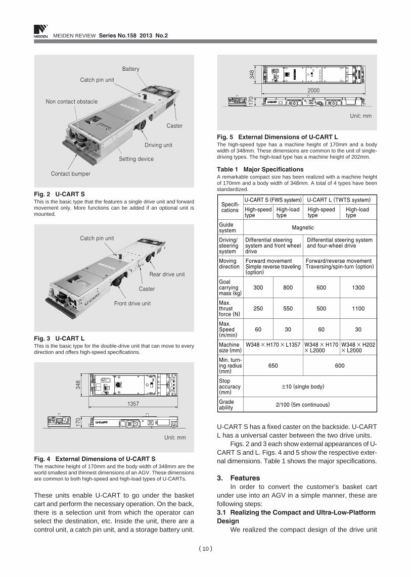
These units enable U-CART to go under the basketcart and perform the necessary operation. On the back,there is a selection unit from which the operator canselect the destination, etc. Inside the unit, there are acontrol unit, a catch pin unit, and a storage battery unit.
U-CART S has a fixed caster on the backside. U-CARTL has a universal caster between the two drive units.
Figs. 2 and 3 each show external appearances of U-CART S and L. Figs. 4 and 5 show the respective exter-nal dimensions. Table 1 shows the major specifications.
3. Features In order to convert the customer’s basket cart
under use into an AGV in a simple manner, these arefollowing steps: 3.1 Realizing the Compact and Ultra-Low-PlatformDesign
We realized the compact design of the drive unit
Battery
Catch pin unit
Non contact obstacle
Setting device
Driving unit
Caster
Contact bumper
Fig. 2 U-CART SThis is the basic type that the features a single drive unit and forwardmovement only. More functions can be added if an optional unit ismounted.
Catch pin unit
Front drive unit
Caster
Rear drive unit
Fig. 3 U-CART LThis is the basic type for the double-drive unit that can move to everydirection and offers high-speed specifications.
1357
Unit: mm
348
170
Fig. 4 External Dimensions of U-CART SThe machine height of 170mm and the body width of 348mm are theworld smallest and thinnest dimensions of an AGV. These dimensionsare common to both high-speed and high-load types of U-CARTs.
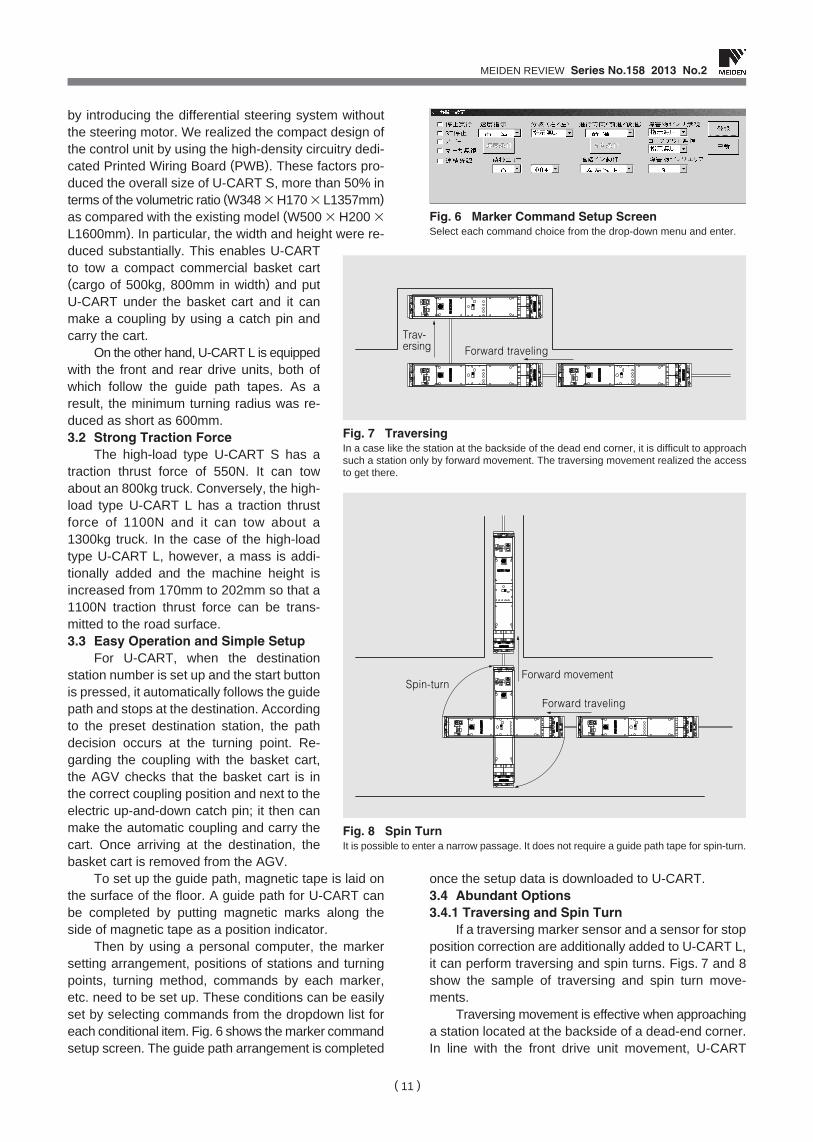
2000
348
170
Unit: mm
Fig. 5 External Dimensions of U-CART LThe high-speed type has a machine height of 170mm and a bodywidth of 348mm. These dimensions are common to the unit of single-driving types. The high-load type has a machine height of 202mm.
Table 1 Major SpecificationsA remarkable compact size has been realized with a machine heightof 170mm and a body width of 348mm. A total of 4 types have beenstandardized.
Specifi-cations
U-CART S (FWS system)
High-speedtype
High-speedtype
High-loadtype
High-load type
300
250
60
800
550
30
600
500
60
1300
1100
30
U-CART L (TWTS system)
Guide system Magnetic
±10 (single body)
2/100 (5m continuous)
Differential steering system and front wheeldrive
W348 × H170 × L1357 W348 × H170× L2000
W348 × H202× L2000
Differential steering systemand four-wheel drive
650 600
Forward movementSimple reverse traveling(option)
Forward/reverse movementTraversing/spin-turn (option)
Driving/steering system
Moving direction
Goal carrying mass (kg)
Max. thrust force (N)
Max. Speed (m/min)
Machinesize (mm)
Min. turn-ing radius(mm)
Stop accuracy (mm)
Grade ability
MEIDEN REVIEW Series No.158 2013 No.2
( )11
by introducing the differential steering system withoutthe steering motor. We realized the compact design ofthe control unit by using the high-density circuitry dedi-cated Printed Wiring Board (PWB). These factors pro-duced the overall size of U-CART S, more than 50% interms of the volumetric ratio (W348 ×H170 × L1357mm)as compared with the existing model (W500 × H200 ×L1600mm). In particular, the width and height were re-duced substantially. This enables U-CARTto tow a compact commercial basket cart(cargo of 500kg, 800mm in width) and putU-CART under the basket cart and it canmake a coupling by using a catch pin andcarry the cart.
On the other hand, U-CART L is equippedwith the front and rear drive units, both ofwhich follow the guide path tapes. As aresult, the minimum turning radius was re-duced as short as 600mm. 3.2 Strong Traction Force
The high-load type U-CART S has atraction thrust force of 550N. It can towabout an 800kg truck. Conversely, the high-load type U-CART L has a traction thrustforce of 1100N and it can tow about a1300kg truck. In the case of the high-loadtype U-CART L, however, a mass is addi-tionally added and the machine height isincreased from 170mm to 202mm so that a1100N traction thrust force can be trans-mitted to the road surface. 3.3 Easy Operation and Simple Setup
For U-CART, when the destinationstation number is set up and the start buttonis pressed, it automatically follows the guidepath and stops at the destination. Accordingto the preset destination station, the pathdecision occurs at the turning point. Re-garding the coupling with the basket cart,the AGV checks that the basket cart is inthe correct coupling position and next to theelectric up-and-down catch pin; it then canmake the automatic coupling and carry thecart. Once arriving at the destination, thebasket cart is removed from the AGV.
To set up the guide path, magnetic tape is laid onthe surface of the floor. A guide path for U-CART canbe completed by putting magnetic marks along theside of magnetic tape as a position indicator.
Then by using a personal computer, the markersetting arrangement, positions of stations and turningpoints, turning method, commands by each marker,etc. need to be set up. These conditions can be easilyset by selecting commands from the dropdown list foreach conditional item. Fig. 6 shows the marker commandsetup screen. The guide path arrangement is completed
once the setup data is downloaded to U-CART. 3.4 Abundant Options 3.4.1 Traversing and Spin Turn
If a traversing marker sensor and a sensor for stopposition correction are additionally added to U-CART L,it can perform traversing and spin turns. Figs. 7 and 8show the sample of traversing and spin turn move-ments.
Traversing movement is effective when approachinga station located at the backside of a dead-end corner.In line with the front drive unit movement, U-CART
Fig. 6 Marker Command Setup ScreenSelect each command choice from the drop-down menu and enter.
Forward travelingTrav-ersing
Fig. 7 TraversingIn a case like the station at the backside of the dead end corner, it is difficult to approachsuch a station only by forward movement. The traversing movement realized the accessto get there.
Forward movement
Forward traveling
Spin-turn
Fig. 8 Spin TurnIt is possible to enter a narrow passage. It does not require a guide path tape for spin-turn.
MEIDEN REVIEW Series No.158 2013 No.2
( )12
follows the guide path tape. The rear-drive unit adjuststhe speed and steering angle in synch with those fromthe front driving unit. Using the sensor for stop positioncorrection that U-CART detects, the forward travelingguide path tape compensates the incline of the machinecaused during the traversing movement; then U-CARTstops in the correct position. The spin-turn is usefulwhen entering a different direction in a narrow path.For stoppage, the sensor for stop position correction isused in the same manner as in the case for traversingmovement.
To improve safety for traversing, non contactobstacle for traversing and a side bumper are availableoptions. 3.4.2 Automatic Battery Charger
When the rear part of U-CART is equipped with anextension box including charger terminals and an auto-matic battery charger is installed on the ground, it real-izes a transportation system which could run by 24/7without changing batteries.
The automatic battery charger uses the current-limiting type constant-voltage method and the batteryvoltage is always monitored to ensure the effectivecharging in a short amount of time. Battery chargingstarts when U-CART arrives at the designed chargingposition and the charger terminals of U-CART come incontact with the ground-level. At that time, to avoidincorrect charging with other matter by an accidentalcontact with the ground charger terminal, charging
commences only when correct battery connection isconfirmed to be connected.
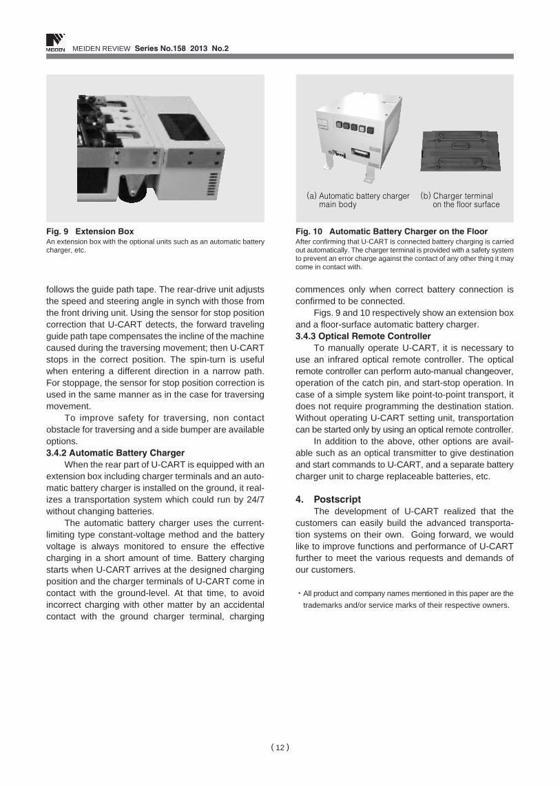
Figs. 9 and 10 respectively show an extension boxand a floor-surface automatic battery charger. 3.4.3 Optical Remote Controller
To manually operate U-CART, it is necessary touse an infrared optical remote controller. The opticalremote controller can perform auto-manual changeover,operation of the catch pin, and start-stop operation. Incase of a simple system like point-to-point transport, itdoes not require programming the destination station.Without operating U-CART setting unit, transportationcan be started only by using an optical remote controller.
In addition to the above, other options are avail-able such as an optical transmitter to give destinationand start commands to U-CART, and a separate batterycharger unit to charge replaceable batteries, etc.
4. Postscript The development of U-CART realized that the
customers can easily build the advanced transporta-tion systems on their own. Going forward, we wouldlike to improve functions and performance of U-CARTfurther to meet the various requests and demands ofour customers.
・All product and company names mentioned in this paper are the
trademarks and/or service marks of their respective owners.
Fig. 9 Extension BoxAn extension box with the optional units such as an automatic batterycharger, etc.
(a) Automatic battery chargermain body
(b) Charger terminal on the floor surface
Fig. 10 Automatic Battery Charger on the FloorAfter confirming that U-CART is connected battery charging is carriedout automatically. The charger terminal is provided with a safety systemto prevent an error charge against the contact of any other thing it maycome in contact with.