Embed Size (px)
Citation preview
Application Examples
Machine Loading Picking Packing/Casing
Assembling Deburring Finishing
Inspection Sealing
●The specifications are subject to changes without notice.●In case that an end user uses this product for military purpose or production of weapon, this product may be liable for the subject of export restriction stipulated in the Foreign Exchange and Foreign Trade Control Law. Please go through careful investigation and necessary formalities for export.
CATALOG NO. R7702E-2
2013.09.U-ABE-ABE
www.nachi.com
Tokyo Head OfficeShiodome Sumitomo Bldg. 17F 1-9-2 Higashi-shinbashi, Minato-ku, Tokyo 105-0021, JAPANTel: +81-(0)3-5568-5245 Fax: +81-(0)3-5568-5236
Toyama Head Office1-1-1 Fujikoshi-Honmachi, Toyama 930-8511, JAPANTel: +81-(0)76-423-5111 Fax: +81-(0)76-493-5211
NACHI ROBOTIC SYSTEMS INC.22285 Roethel Drive, Novi, Michigan, 48375, U.S.A. Tel: +1-248-305-6545 Fax: +1-248-305-6542URL: http://www.nachirobotics.com/ E-mail:[email protected]
NACHI BRASIL LTDA. SAO PAULO BRANCHAv. Paulista, 453, Primeiro Andar, Conj, 11, 12, 12 e 14, Cerqueira Cesar, Sao Paulo-SP, CEP: 01311-000, BRASILTel: +55-11-3284-9844 Fax: +55-11-3284-1751
NACHI EUROPE GmbHBischofstrasse 99, 47809, Krefeld, GERMANYTel: +49-(0)2151-65046-0 Fax: +49-(0)2151-65046-90 URL: http://www.nachi.de/
NACHI TECHNOLOGY (THAILAND) CO., LTD. BANGKOK SALES OFFICEUnit 23/109(A),Fl.24th Sorachai Bldg., 23 Sukhumvit 63 Road(Ekamai), Klongtonnua,Wattana, Bangkok 10110, THAILAND Tel: +66-2-714-0008 Fax: +66-2-714-0740
PT.NACHI INDONESIAJI.H.R.Rasuna Said Kav.X-O Kuningan, Jakarta 12950, INDONESIATel: +62-021-527-2841 Fax: +62-021-527-3029
NACHI-FUJIKOSHI CORP. KOREA REPRESENTATIVE OFFICE3F A-Youn Digital Tower, 314-37, Seongsu-dong 2-ga, Seongdong-gu, Seoul,133-120, KoreaTel: +82-(0)2-469-2254 Fax: +82-(0)2-469-2264
NACHI KG TECHNOLOGY INDIA PTE. LTD.Unit No.207,Sewa Corporate Park,MG Road,Iffco Chowk,Gurgaon-122001, INDIATel: +91-124-450-2900 Fax: +91-124-450-2910
NACHI (AUSTRALIA) PTY. LTD.Unit 1, 23-29 South Street, Rydalmere, N.S.W, 2116, AUSTRALIATel: +61-(0)2-9898-1511 Fax: +61-(0)2-9898-1678URL: http://www.nachi.com.au/
NACHI SINGAPORE PTE. LTD.No.2 Joo Koon Way, Jurong Town, Singapore 628943, SINGAPORETel: +65-65587393 Fax: +65-65587371
Ultra High Speed and compact
MZ07CATALOG
Cable routing improved
189.
5
190.5
Characteristics
Robot body
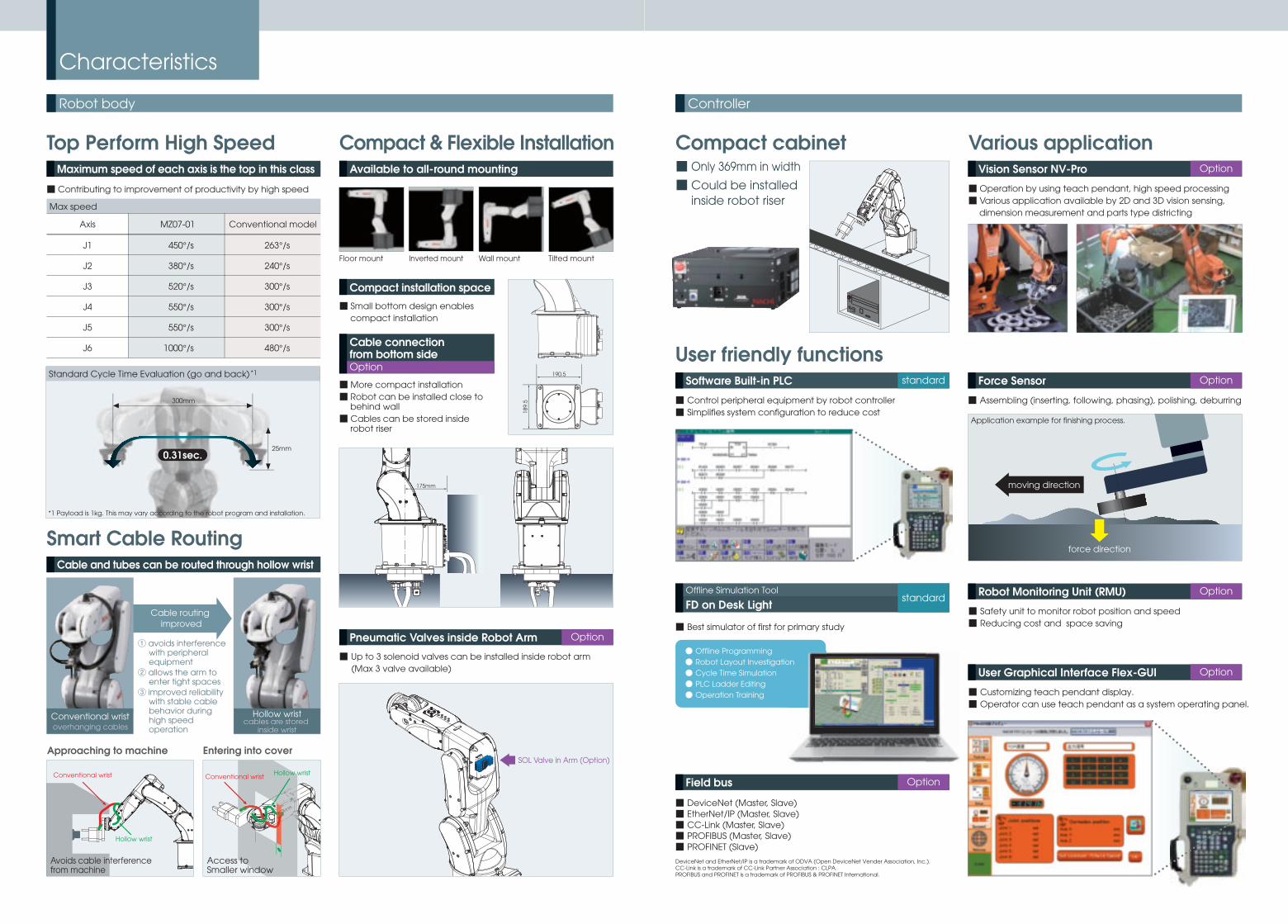
Smart Cable Routing
Hollow wristcables are stored
inside wrist
Conventional wristoverhanging cables
Approaching to machine Entering into cover
■ Small bottom design enables compact installation
■ Contributing to improvement of productivity by high speed
Top Perform High Speed
Max speed
450°/s
380°/s
520°/s
550°/s
550°/s
1000°/s
MZ07-01
263°/s
240°/s
300°/s
300°/s
300°/s
480°/s
Conventional model
J1
J2
J3
J4
J5
J6
Axis
Compact & Flexible Installation
Floor mount Inverted mount Wall mount Tilted mount
■ Up to 3 solenoid valves can be installed inside robot arm (Max 3 valve available)
■ More compact installation■ Robot can be installed close to
behind wall■ Cables can be stored inside
robot riser
Conventional wrist
Hollow wrist
Conventional wrist Hollow wrist
Access toSmaller window
SOL Valve in Arm (Option)
175mm
Avoids cable interferencefrom machine
① avoids interference with peripheral equipment
② allows the arm to enter tight spaces
③ improved reliability with stable cable behavior during high speed operation
Maximum speed of each axis is the top in this class
Cable and tubes can be routed through hollow wrist
Available to all-round mounting
Pneumatic Valves inside Robot Arm Option
Compact installation space
Cable connectionfrom bottom sideOption
Standard Cycle Time Evaluation (go and back) *1
*1 Payload is 1kg. This may vary according to the robot program and installation.
300mm
25mm0.31sec.
Controller
● Offline Programming● Robot Layout Investigation● Cycle Time Simulation● PLC Ladder Editing● Operation Training
■ Assembling (inserting, following, phasing), polishing, deburring
Application example for finishing process.
Various application
■ Operation by using teach pendant, high speed processing■ Various application available by 2D and 3D vision sensing,
dimension measurement and parts type districting
User friendly functions
■ Control peripheral equipment by robot controller■ Simplifies system configuration to reduce cost
■ Best simulator of first for primary study
Compact cabinet
■ Customizing teach pendant display.■ Operator can use teach pendant as a system operating panel.
moving direction
force direction
■ Only 369mm in width
■ Could be installed inside robot riser
Vision Sensor NV-Pro Option
Force Sensor Option
■ Safety unit to monitor robot position and speed■ Reducing cost and space saving
Robot Monitoring Unit (RMU) Option
■ DeviceNet (Master, Slave)■ EtherNet/IP (Master, Slave)■ CC-Link (Master, Slave)■ PROFIBUS (Master, Slave)■ PROFINET (Slave)
DeviceNet and EtherNet/IP is a trademark of ODVA (Open DeviceNet Vender Association, Inc.).CC-Link is a trademark of CC-Link Partner Association : CLPA.PROFIBUS and PROFINET is a trademark of PROFIBUS & PROFINET International.
Field bus Option
User Graphical Interface Flex-GUI Option
Software Built-in PLC standard
FD on Desk LightOffline Simulation Tool
standard
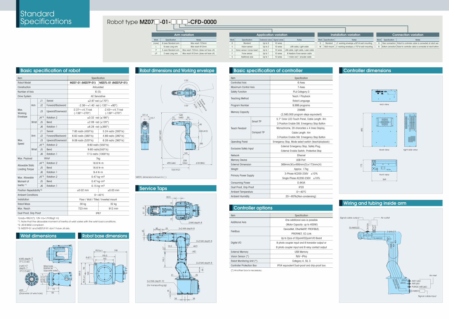
Wiring and tubing inside arm
Standard Specifications
Wrist dimensions
Controller dimensionsRobot dimensions and Working envelope
Service Taps
Robot base dimensions
Basic specification of robot
J1
J2
J3
J4*3
J5
J6
J1
J2
J3
J4*3
J5
J6
J4*3
J5
J6
J4*3
J5
J6
Swivel
Forward/Backward
Upward/Downward
Rotation 2
Bend
Rotation 1
Swivel
Forward/Backward
Upward/Downward
Rotation 2
Bend
Rotation 1
Rotation 2
Bend
Rotation 1
Rotation 2
Bend
Rotation 1
Item
Robot Model
Construction
Number of Axis
Drive System
Position Repeatability*2
Ambient Conditions
Installation
Robot Mass
Max. Reach
Dust Proof, Drip Proof
Max. Working Envelope
Max. Speed
Max. Payload
Allowable Static Loading Torque
Max. Allowable Moment of Inertia *1
Wrist
Arm
Wrist
Arm
Wrist
490
173
369
front view
level view right side view
rear view
Controller options
1[rad]=180/π[°], 1[N・m]=1/9.8[kgf・m]
*1: Note that the allowable moment of inertia of wrist varies with the wrist load conditions.
*2: JIS B 8432 compliant.
*3: MZ07P-01 and MZ07LP-01 don’t have J4 axis.
Basic specification of controller
(*) Another box is necessary.
Robot type MZ07□-01-□□□-CFD-0000
CFD controller
Power Cable(Prepared by customer)
Power Cable(Prepared by customer)
USB memory (1GB)12
49(
1602) 330(410)330(410)
345345
45
50340(440)
340(440)7373
495(646)
723(912)
228(266)
228(266) 618(806)
165
MZ07L dimensions shown in ( )
Frame
interference
radius
R150170°
170°
221.4110.7
189.
5
160
4-φ11
95.5
±0.
194
160
190.5
95.5±0.1 198
10-AWG22
60.5
2-M4 depth 8
2×2-M4 depth 8
2×2-M4 depth 8
2×2-M4 depth 8
2×2-M6 depth 10
80 25
44.9
25
(45)
10.2
31
3434
1515
25
3.7
18
193.
1
65
6161
AW
G25×6p
AW
G25×6p
2-φ4×2.5
φ6×4 AIR1(φ6)
CNR010
AIR(φ6)PURGE AIR(φ6)
φ6×4
10-AWG23
CN
10A
Po
rt7
CN61
A
CN62
A
CN60
A
CN60
B
Po
rt1
Air outletSignal cable output
(for transporting jig)
4-M5 depth 7(P.C.D.60)
φ23
(Diameter of wire hole)
(P.C.D.60)
φ72
h7
φ45
h7
83
73
23
2-φ5 H7 depth 7
14
Air inlet
Signal cable input
Wire hole(same as opposite side)
Specification
Articulated
6 (5)
AC Servodrive
±2.97 rad (±170°)
-2.36~+1.40 rad (-135°~ +80°)
±3.32 rad (±190°)
±2.09 rad (±120°)
±6.28 rad (±360°)
9.60 rad/s (550°/s)
9.60 rad/s(550°/s)
17.5 rad/s (1000°/s)
7kg
16.6 N・m
16.6 N・m
9.4 N・m
0.47 kg・m2
0.47 kg・m2
0.15 kg・m2
0~45°C
Floor / Wall / Tilted / Inverted mount
IP67
7.85 rad/s (450°/s)
6.63 rad/s (380°/s)
9.08 rad/s (520°/s)
MZ07-01 (MZ07P-01)
30 kg
723 mm
±0.02 mm
5.24 rad/s (300°/s)
4.89 rad/s (280°/s)
6.28 rad/s (360°/s)
32 kg
912 mm
±0.03 mm
MZ07L-01 (MZ07LP-01)
Connection variationMark
0
B
Specification
Rear connection
Bottom connection
Notes
Robot to controller cable is connected at robot rear
Robot to controller cable is connected at robot bottom
Arm variationSpecification
6 axes Standard arm
6 axes Long arm
5 axes Standard arm
5 axes Long arm
Notes
Max reach 723mm
Max reach 912mm
Max reach 723mm (does not have J4)
Max reach 912mm (does not have J4)
Mark
(none)
L
P
LP
Application variationSpecification
Standard
Vision sensor
Vision sensor (cross laser)Force sensor
Additional axis
Solenoid valve
Up to 3
Up to 2
Up to 1
Up to 1
Up to 1
Signal wires
10 wires
10 wires
10 wires
10 wires
10 wires
Notes
-
LAN cable, Light cable
LAN cable, Light cable, Laser cable
6 freedom Force sensor cable
1 motor and 1 encoder cable
Mark
0
V
U
F
S
Installation variationSpecification
Standard
Wall mount
Notes
J1 working envelope ±30°at wall mounting
J1 working envelope ±170°at wall mounting
Mark
0
W
Specification
One additional axis is possible
(Motor Capacity: up to 400W)
DeviceNet, EtherNet/IP, PROFIBUS,
PROFINET, CC-Link
Up to 2pcs of 32point/32point I/O Board
8 photo coupler input and 8 transistor output or
8 photo coupler input and 8 relay contact output
USB Memory
NV-ProCategory 4, SIL 3
IP54 equivalent Dust-proof and drip-proof box
Item
External Memory
Vision Sensor (*)
Robot Monitoring Unit (*)
Controller Protection Box
Fieldbus
Additional Axis
Digital I/O
Specification
6-Axes
7-Axes
PLd Category-3
Teach / Playback
Robot Language
9,999 programs
256MB
(2,560,000 program steps equivalent)
5.7” Color LCD Touch Panel, Cable Length: 4m
3 Position Enable SW, Emergency Stop Button
Monochrome, 20 characters x 4 lines Display,
Cable Length: 4m
3 Position Enable SW, Emergency Stop Button
Emergency Stop, Mode select switch (teach/playback)
External Emergency Stop, Safety Plug,
External Enable Switch, Protective Stop
Ethernet
USB Port
369mm(W)×490mm(D)×173mm(H)
Approx. 17kg
3-Phase AC200-230V ±10%
Single Phase AC200-230V ±10%
0.4KVA
IP20
0~40°C
20~85%(Non-condensing)
Item
Controlled Axis
Maximum Control Axis
Safety Function
Program Number
Operating Panel
Network
Memory Device
External Dimension
Weight
Consuming Power
Dust Proof, Drip Proof
Ambient Temperature
Ambient Humidity
Teaching Method
Memory Capacity
Teach Pendant
Compact TP
Smart TP
Exclusive Safety Input
Primary Power Supply
-2.37~+4.71rad(-136°~270°)
-2.43~+4.71rad(-139°~270°)
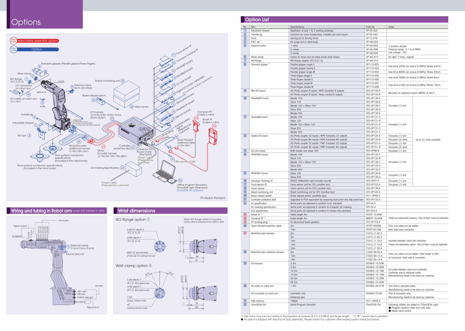
Wrist dimensions
Options Option List
ISO flange option ⑦
Wrist clamp option ⑥
Option
①②③④⑤
⑥⑦⑧
⑨
⑩
⑪
⑫
⑬⑭
⑮
⑯⑰⑱⑲⑳㉑㉒
㉓㉔㉕㉖
㉗
㉘
㉙
㉚
㉛32
TP=Teach Pendant
When ISO flange option is mounted, hollow size is reduced from φ23 to φ20
Adjustable stopper
IP67 set
Solenoid valves(1 pcs/ 2 pcs /3 pcs)
Solenoid valveUp to (3) valves
Vision sensor
Brake release switch
I/O harness(L=2.5m,5.5m,10.5m,15.5m,20.5m,25.5m)
MotorEncoder harness(L=2m,5m,10m,15m,20m)
Motor/Encoder additional harness(L=5m,10m,15m)
Floor surface connection specifications(included in the robot body)
Floor surface connection specifications(included in the robot body)
Robot monitoring unit
Transfer jig
Tools
CFD controllerCFD controller
Controllerprotection Box Connector for
Power Cable(Standard)
CE marking Specification
Power Cable(Prepared by customer)
Power Cable(Prepared by customer)
Power Cable(Prepared by customer)Power Cable(Prepared by customer)
Teach Pendant additional cable(L=5m,10m)
Smart TP(Cable L=4m)
Compact TP(Cable L=4m)
Standard gripper (Parallel gripper/Three fingers)
*1 Grip force may vary according to the supplied air pressure (0.3 to 0.5 MPa) and finger length. *2 “TP” means teach pendant.● All option is shipped with robot by kit (sub assembly). Please install it by customer after reading option install procedure.
Mini I/O board
TP shortin
g
plug
External sa
fety
signal
(Prepared by
customer)
EtherNet/IP board
DeviceNet board
Digital I/O
board (NPN/PNP)
CC-Link boardPROFIBUS boardPROFINET b
oard Conveyor Tr
acking I/F
Force sensor I/
F
ISO flange(P.C.D.31.5)
Wires clamp
CNRO10(connector included
in the I/O harness option)
CN10A
MZ07*-01
I/O cable on robot arm(L=1.5m)
I/O connector on robot arm
Offline Program SimulationFDonDESK Light (Standard)FDonDESK Pro (Option)
USB memory (1GB)USB memory (1GB)
330(410)
345
340(440)73
228(266)
10-AWG22
7-φ4×2.5
AIR1(φ6)
CNR010
AIR(φ6)PURGE AIR(φ6)
AW
G25×6p
AW
G25×6p
φ6×4φ6×4
CN
10A
10-AWG23
CN61
A
CN62
A
CN60
A
CN60
B
Po
rt7
Po
rt1(
SO
L1A)
Po
rt1(
SO
L1B)
Po
rt1(
SO
L2A)
Po
rt1(
SO
L2B)
Po
rt1(
SO
L3A)
Po
rt1(
SO
L3B)
Exhaust (silencer)
Air outlet
Signal output
2-φ5 H7 depth 6
2-φ5 depth 7
φ72
h7
φ40
h8
φ72
h7
φ45
h7
φ20* H7 penetrated
(hole size for wiring hollow)
4-M5 depth 7
22.5°22.5°
(P.C.D. 31.5)
(P.C.D. 60 balanced)
4-M5 depth 7
(P.C.D. 60 balanced)
7-φ4
(tube clamp hole)
φ7
(wiring clamp hole)
88
93
100
7
7
95
(P.C.D. 31.5)
Air inlet
Signal input
Wiring and tubing in Robot arm (when SOL installed in arm)
Red mark
Blue mark
selectable essential option
Specifications
Restriction of axis 1 to 3 working envelope
Common for crane transporting, inverted and wall mount
Zeroing pin & Zeroing block
Air purge unit in robot body
1 valve
2 valves
3 valves
Clamp for wires and air tubes inside wrist hollow
ISO flange adapter (P.C.D.31.5)
Parallel gripper single S
Parallel gripper double S
Parallel gripper single M
Three fingers single S
Three fingers double S
Three fingers single M
Three fingers double M
I/O Photo coupler 8 inputs / NPN Transistor 8 outputs
I/O Photo coupler 8 inputs / Relay contact 8 outputs
Master 1CH
Slave 1CH
Master 1CH + Slave 1CH
Slave 2CH
Master 2CH
Master 1CH
Slave 1CH
Master 1CH +Slave 1CH
Slave 2CH
Master 2CH
I/O Photo coupler 32 inputs / NPN Transistor 32 outputs
I/O Photo coupler 64 inputs / NPN Transistor 64 outputs
I/O Photo coupler 32 inputs / PNP Transistor 32 outputs
I/O Photo coupler 64 inputs / PNP Transistor 64 outputs
Both master and slave 1CH
Master 1CH
Slave 1CH
Master 1CH + Slave 1CH
Slave 2CH
Master 2CH
Slave 1CH
Slave 2CH
RS422 Differential input encoder counter
Force sensor unit for CFD (another box)
Vision sensor unit for CFD (another box)
Robot monitoring unit for CFD (another box)
Brake release switch (portable type)
Upgraded to IP54 equivalent by preparing dust-proof and drip-proof box
Some parts are replaced to conform to UL standard
Some parts are replaced to conform to European CE marking
Some parts are replaced to conform to Korean KCs standard
Cable length 4m
Cable length 4m
To disconnect teach pendant
5m
10m
2m
5m
10m
15m
20m
5m
10m
15m
2.5m
5.5m
10.5m
15.5m
20.5m
25.5m
1.5m
Connector only
Soldering type
1GByte
Robot Program Simulator
Parts No.
OP-S5-022
OP-S2-042
OP-T2-078
OP-H9-004
OP-H4-004
OP-H5-008
OP-H6-004
OP-W3-012
OP-W2-012
OP-F10-002
OP-F10-003
OP-F10-004
OP-F10-005
OP-F10-006
OP-F10-007
OP-F10-008
CFD-OP150-A
CFD-OP150-B
CFD-OP130-A
CFD-OP130-B
CFD-OP130-C
CFD-OP130-D
CFD-OP130-E
CFD-OP131-A
CFD-OP131-B
CFD-OP131-C
CFD-OP131-D
CFD-OP131-E
CFD-OP125-A
CFD-OP125-B
CFD-OP151-A
CFD-OP151-B
CFD-OP98-B
CFD-OP132-A
CFD-OP132-B
CFD-OP132-C
CFD-OP132-D
CFD-OP132-E
CFD-OP136-B
CFD-OP136-D
CFD-OP47-A
CFD-OP152-A
CFD-OP139-A
CFD-OP145-A
FD11-OP90-E
CFD-OP133-A
CFD-UL-A
CFD-CE-A
CFD-KCS-A
CFDTP-10-04M
MINITP-10-04M
CFD-OP153-A
CFDTP-RC05M
CFDTP-RC10M
Z101C-J1-02-A
Z101C-J1-05-A
Z101C-J1-10-A
Z101C-J1-15-A
Z101C-J1-20-A
Z102C-00-05-A
Z102C-00-10-A
Z102C-00-15-A
IOCABLE-10-02M
IOCABLE-10-05M
IOCABLE-10-10M
IOCABLE-10-15M
IOCABLE-10-20M
IOCABLE-10-25M
IOCABLE-20-01M
IOCABLE-20-00
FD11-OP93-A
FDonDESK Pro
Item
Adjustable stopper
Transfer jig
Tools
IP67 set
Solenoid valve
Wires clamp
ISO flange
Standard gripper *1
Mini I/O board
EtherNet/IP board
DeviceNet board
Digital I/O board
CC-Link board
PROFIBUS board
PROFINET board
Conveyor Tracking I/F
Force sensor I/F
Vision sensor
Robot monitoring unit
Brake release switch
Controller protection BOX
UL specification
CE marking specification
KCs specification
Smart TP *2
Compact TP *2
TP shorting plug *2
Teach Pendant extention cable
Motor/Encoder harness
Motor/Encoder extention harness
I/O harness
I/O cable on robot arm
I/O connector on robot arm
USB memory
FDonDESK Pro
Notes
Air (φ4:7 lines), signals
Grip force 600N (air source 0.5MPa) Stroke 30mm
Occupies (1) slot
Occupies (2) slots
Occupies (1) slot
Occupies (2) slots
Occupies (1) slot
Occupies (1) slot
Occupies (1) slot
Only one cable can be added.
Both side have connector
Tool side is separate cable.
Manufacturing needs to be done by customer.
This is connector only.
Manufacturing needs to be done by customer.
Following utilities are added on “FDonDESK Light”● Program creation utility from CAD data● Muklti robot control
2 position doublePressure range : 0.1 to 0.5MPaCoil voltage : 24V
Occupies (1) slot
Occupies (1) slot
Occupies (1) slot
Occupies (1) slot
Harness between robot and controller
These are selectable option. One of them must be selected.
Only one cable can be added. Total length is 25m
at maximum. Both side is connector
I/O cable between robot and controller. Controller side is separate cable. Manufacturing needs to be done by customer.
Grip force 320N (air source 0.5MPa) Stroke 24mm
Grip force 300N (air source 0.5MPa) Stroke 8mm
Grip force 410N (air source 0.5MPa) Stroke 10mm
Mounted on sequence board UM352 of slot A
These are selectable options. One of them must be selected.
Up to (2) slots available
No.
(to customer auxiliary equipment)