Embed Size (px)
Citation preview

Kennesaw State UniversityDigitalCommons@Kennesaw State University
Senior Design Project For Engineers
Spring 2018
Ultra Efficient Commercial Transport Challenge-NASA Design Challenge- X-JAB-ECTRamin AbdulKennesaw State University
Jacob BeitingKennesaw State University
Evan JohnstonKennesaw State University
Follow this and additional works at: https://digitalcommons.kennesaw.edu/egr_srdsn
Part of the Aerospace Engineering Commons
This Senior Design is brought to you for free and open access by DigitalCommons@Kennesaw State University. It has been accepted for inclusion inSenior Design Project For Engineers by an authorized administrator of DigitalCommons@Kennesaw State University. For more information, pleasecontact [email protected].
Recommended CitationAbdul, Ramin; Beiting, Jacob; and Johnston, Evan, "Ultra Efficient Commercial Transport Challenge- NASA Design Challenge- X-JAB-ECT" (2018). Senior Design Project For Engineers. 3.https://digitalcommons.kennesaw.edu/egr_srdsn/3

Ultra Efficient Commercial Transport Challenge
NASA Design Challenge
X-JAB-ECT
Kennesaw State University
Dr. Adeel Khalid
By: Ramin Abdul, Jacob Beiting, and Evan Johnston

Table of Contents
Executive Summary……………….………………………………………………………………2
Introduction………………………………………………………………………………………..3
System Overview…………………………………………………………………………....…….4
Design Requirements……………………………………………………………………………...5
Design Concepts and Trade Study………………………………………………………………...7
Available Required Resources………………………………………………………………….....9
Budget……………………………………………………………………………………………..9
Conceptual Design………………………………………………………………………………...9
Airfoil Selection………………………………………………………………………………….12
Preliminary Design………………………………………………………………………………15
Problems Encountered…………………………………………………………………………...16
Final Design……………………………………………………………………………………...17
Engine Sizing and Design………………………………………………………………………..18
Flow Simulation Results………………………………………………………………………....19
Conclusion……………………………………………………………………………………….22
Gantt Chart…………………………………………………………………………………….....22
Appendices…………………………………………………………………………………….....23
Calculations……………………………………………………………………………………....23
Formulas Used…………………………………………………………………………………...27
References………………………………………………………………………………………..30
1

Executive Summary
Today’s aircraft require new innovation to be able to produce the same amount of lift, but
with the design decrease the amount of drag produced. The X-JAC ECT has the ability and is an
innovative airframe to reduce today’s fuel costs. The baseline comparison for the X-JAB is the
Boeing 747-400 aircraft, the payload, range, speed, and altitude are the same for the X-JAB and
the 747. Through use of supercritical airfoils, the X-JAB was designed as a blended wing body
aircraft to produce more lift while evenly balancing the weight of the aircraft and the payload.
Through parametric analysis and flow simulations, the X-JAB is able to achieve a 31.6%
reduction in fuel costs compared to the Boeing 747-400.
2

Team Members
Ramin Abdul - Structural and Layout Engineer, Design Engineer
Jacob Beiting - Project Manager, Design Engineer
Evan Johnston - Propulsion and Energy Engineer, Design Engineer
Introduction
The overall goal of this project is a challenge presented by NASA; the challenge is to
design an ultra efficient commercial transport for 2045 with the potential to surpass 30%-60%
reduction of energy. The basis for comparison of the X-JAB is a 2005 best-in-class aircraft, we
have chosen the Boeing 747-400 as the basis for our aircraft. The overall task of this challenge is
to achieve a dramatic reduction in energy consumption through innovative airframe and
propulsion systems, new approaches to integration of the airframe and propulsion systems, and
new operational paradigms.
3

Figure 1: NASA’s Strategic Implementation Plan
Figure 1 shows NASA’s targeted improvements in subsonic transportation system
metrics for the next few decades.
System Overview
The baseline aircraft is the Boeing 747-400:
Figure 2: Dimensions of 747-400 Figure 3: Range of 747-400
Design Requirements
Specific mission requirements are dictated by the Boeing 747-400. The newly designed
aircraft concept must have the same or better mission performance capabilities as the baseline
comparison.
Figure 4: GE Performance Figure 5: P&W Performance
4

Figure 6: Rolls-Royce Performance
Figure 7: Mission Profile 747-400
Figure 8: Full passenger payload
5

Other design requirements include the needs of possible passengers, passenger acceptance,
development cost and risk, and FAA certification. Special considerations need to be if part of the
design features are incompatible with current FAA regulations or passenger expectations. Ideally
designs would like to be within today’s ground infrastructure, but designs that require changes to
infrastructure are allowed but the final report must address the practicality and implementation
challenges of any of the required changes needed. Changes made to flight operations to improve
the efficiency need to be addressed for cost and scheduling impacts to the air transportation
system.
Figure 9: NASA Challenge Mission Requirements
Design Concepts and Trade Study
The challenge itself calls for an innovative airframe, the group has decided that we will
design a blended wing aircraft for commercial transportation. Since this is a design challenge for
the year 2045, information for a blended wing aircraft is limited in terms of commercial aircrafts.
Boeing has two experimental blend prototypes the X-45 and the X-48. The X-45 is an unmanned
combat air vehicle and the X-48 is an unmanned aerial vehicle both in partnership with NASA.
Fortunately we also have the Lockheed F-117 Nighthawk to study as well.
6

Figure 10: Boeing X-45
Figure 11: Boeing/NASA X-48
7

Figure 12: Lockheed F-117 Nighthawk
Due to the fact that there is not any commercial blended wing aircraft all designs and research
will have to be considered experimental.
Analysis and Verification Process/Minimum Success Criteria:
For analysis and verification of the chosen design, SOLIDWORKS Computational Fluid
Dynamics will be used. Due to the experimental design, many iterations are expected till the
final design requirement of a 30-60% reduction in energy is achieved. Once a 30-60% reduction
is met, we would like to 3D print the prototype design and test it in the school’s wind tunnel in
the Fluid Mechanics Laboratory. The minimum success point is the 30- 60% reduction in energy,
ideally the goal is to get the aircraft to achieve and energy reduction in the range of 60%-80%.
Available and Required Resources
Resources needed for this project is the software SOLIDWORKS and its Computational
Fluid Dynamics simulation, which is available for free for students, staff, and faculty. Hardware
required will be the use of a 3D printer and the wind tunnel in the Fluid Mechanics Laboratory.
8

Budget
SOLIDWORKS as stated earlier is free for students of the school and 3D printers are
available for students. A cost on materials has not been calculated as of yet, as we are finding
more information on using the 3D printers and the cost of the material. A program called Aero
Foil was found for inverse airfoil modeling, cost $20 (student copy, when product is available)
Conceptual Design
The design choice as stated earlier is a blended wing model, something akin to the
Boeing X-48. The reason for a blended wing design, is that when the profile of the plane is
viewed from the side, the fuselage is an airfoil.
9

As noted above, looking at the figures, an airfoil shape can be observed from the side profile. For
designing the initial airfoil, a program called Aero Foil was found. The software program can be
obtained from www.AeroFoilEngineering.com. A student edition was obtained for $20, and with
this software we will be able to create the airfoil and submit it into SOLIDWORKS for further
implementation of the overall design of the aircraft. Through a website called grabcad.com, we
were able to obtain a CAD drawing for a blended wing design and a Boeing 747-400.
Figure 17: Blended CAD Drawing
10

Figure 18: Boeing 747-400 CAD Drawing
Figure 19: Side Profile Blended Wing Design
11

Figure 20: Sizing Sketch of BWB
Airfoil Selection
NACA 63015
Surface Velocity Alpha Plot
12

Gamma Plot Pressure Coefficient vs Surface
Figures 21-25: Aerofoil results of NACA 63015
Drag Polar
The initial airfoils presented above were giving data that showed that the flow over the
top of the airfoil at the given parameters of 34,400 ft with a velocity of 255.9 m/s was going
supersonic, and therefore was breaking the speed of sound create supersonic drag and could
damage the airplane as well as increase the drag and lower the efficiency and increase fuel
consumed. Going back through further trade studies that had been done, considering that only a
13
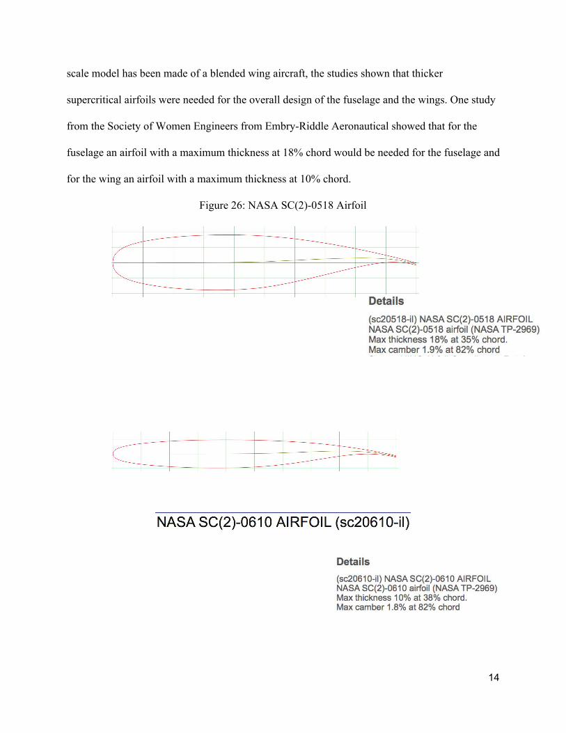
scale model has been made of a blended wing aircraft, the studies shown that thicker
supercritical airfoils were needed for the overall design of the fuselage and the wings. One study
from the Society of Women Engineers from Embry-Riddle Aeronautical showed that for the
fuselage an airfoil with a maximum thickness at 18% chord would be needed for the fuselage and
for the wing an airfoil with a maximum thickness at 10% chord.
Figure 26: NASA SC(2)-0518 Airfoil
14

Figure 27: NASA SC(2)-0610 Airfoil
From searching www.airfoiltools.com the two airfoils above were found for the design,
the SC(2)-0518, airfoil for fuselage, has a max thickness of 18% at 35% of the chord and the
SC(2)-0610, airfoil for wing, has a max thickness of 10% at 38% chord.
Preliminary Design
The initial design was done through hand drawing and calculations the verify sizing, from
the initial design it was determined that the total wingspan of the blended wing body would
41.54 meters and the length of the aircraft would be 24.55 meters. The first iteration of the
aircraft fuselage was not a pretty one, with this being the first aircraft designed for the team, the
results speak for itself.
Figure 28: 1st Iteration
The back of the fuselage is almost flat and takes up to much surface area and allows for turbulent
flow to be created at the end of the fuselage. Going back to the trade studies, it was noticed that
15

the back of the fuselage design was rounded and therefore the 2nd iteration of the aircraft
fuselage would be rounded and allowing for more natural flow off the back of the aircraft.
Figure 29: 2nd Iteration
Problems Encountered
Many problems were encountered when attempting to design this aircraft. The first
problem was overall design, this design for commercial use is something that has not been
produced on a large scale. Stealth aircraft F-117 as noted earlier is more suited overall design for
what is envisioned. The next problem that was encountered was selecting the airfoil for aircraft,
initialing thinking 1 airfoil would suit the overall design needs, but through further research the
SWE BWB noted earlier was implementing 2 seperate airfoils. The initial airfoil that was
decided on was the NACA 63015. From the initial research on the aerofoil software the velocity
on top of the airfoil was going supersonic at the given conditions of 344000 feet and a speed of
255.9 m/s.
The airfoil problem was a big cause for concern, if the aircraft can’t fly at the given
parameters of a Boeing 747-400 series without going supersonic, the project was destined to fail.
16

Through further studying as noted above in the airfoil selection, the need for a supercritical
airfoil was decided for the design of the airplane.
The next problem was bringing the design to life with software, since Solidworks is free
for engineering students at Kennesaw State University. Only being experienced with a couple of
CAD classes, a design of this scale would be challenging. Sometimes importing the airfoil data
into an XYZ curve in Solidworks proved to be challenging. However, the challenges were
overcome and a design was able to be modeled and simulated in Solidworks.
Final Design
The final design was modeled in Solidworks with the SC(2)-0518 for the fuselage and the
SC(2)-0610 for the wing. The overall dimensions for the aircraft are a wingspan of 41.2 meters,
24.53 meters long and is 4.4 meters at the aircrafts thickest point.
Figure 30: Technical Drawing of X-JAB
17

Figure 31: Isometric View of X-JAB
Figures 32-34: Top, Front , and Right views of X-JAB
Engine Sizing and Design
18

The engines of X-JAB-EFT were designed through parametric analysis of an ideal
turbofan engine. The parametric analysis was done to optimize the engines’ thrust specific fuel
consumption during cruise. At the cruise velocity of 255.9 m/s, cruise altitude of 10,000 m, and
altitude density of 0.38856 kg/cu.m, the drag was determined to be an average of 148,000 N. For
4 engines, the average thrust required from each engine is 37,000 N. Using all assumptions and
equations from Appendix A-II, for 4 engines, the thrust specific fuel consumption of the engines
was determined to be 0.000013 (kg/s/N).
For this design, the overall core compression ratio is 60. The fan pressure ratio is 1.3,
with an optimal bypass ratio of 20.24. The temperature entering the core turbine is 1600 K. Each
engine has a core exit velocity of 648.32 m/s, with a bypass exit velocity of 322.6 m/s, a core air
intake of 26.09 kg/s, and a bypass air intake of 528.08 kg/s; the total air intake into each engine
is 554.16 kg/s. Using continuity principle, the inlet area for the core and bypass are determined
to be .264 sq.m and 5.347 sq.m respectively. The pressure ratio across the turbine required to
power the engine is 0.4016, and the fuel to air ratio required to produce the thrust from the given
engine is 0.01848.
With the current iteration of the engine design, the total fuel consumed for the required
range of 11,260 km is 85,397.55 kg. Comparatively, the total fuel consumed for the equivalent
range by a Boeing 747-400 is 124,051 kg, resulting in a 31.16% reduction in fuel consumed by
the X-JAB-EFT.
Analysis
Fuel Consumption Analysis
19

For the final engine design chosen to power the X-JAB aircraft, calculations were made
to compare the fuel consumption on a typical 5 hour cross-country flight from Atlanta, Georgia
to Los Angeles, California to that of the Boeing 747-400. On this 5 hour flight, a Boeing 747-400
will consume 68,576.63 L of fuel. Comparatively, X-JAB will consume 49,227.98 L. A per set
comparison of fuel consumed shows that the Boeing 747-400 will consume 164.85 liters of fuel
per passenger at a max capacity of 416 passengers, compared to X-JAB at 118.37 liters per
passenger at max capacity or 416 passengers. At a cost of 56 cents per liter of Jet A-1 fuel, the
Boeing 747-400 will use $38,098 on this 3,120 km flight, or $91.58 per passenger. X-JAB will
use $27,349 for the same flight, equating to $65.74 per passenger.
The results of a single cross-country flight from Atlanta to Los Angeles show that X-JAB
is able to provide a fuel savings of $25.84 per passenger over a Boeing 747-400. On a fully
booked flight, the total fuel savings equate to $10,749. This fuel savings is significant; if X-JAB
is flown the equivalent of only 3 cross-country flights daily, in a single year, X-JAB will use
$11,770,389.87 less fuel than conventional aircraft in the same class.
Flow Simulation Results
Through Solidworks flow simulations, there is an ability to add global goals to the
simulation to quantify results, the global goals for these flow simulations were set for Av Total
Pressure, Av Velocity, Force is the X direction (drag), and Force in the Y direction(lift). Also
knowing the parameters for density and velocity, as stated above, allowed the ability to calculate
the lift and drag coefficients for different angles of attack. The main goal was steady level flight
for this aircraft to decrease overall fuel consumption by at least 30%. Through flow analysis,
20

with the given parameters the flow going over the aircraft does not go supersonic and therefore
cannot create too much drag or create structural failure.
Figures 35-37: Flow during steady level flight
21

Figure 38: Lift and Drag from Flow Simulations
Conclusion
The X-JAB Ultra Efficient Commercial Transport is able to achieve a 31.6% reduction in
fuel costs compared to the Boeing 747-400. The design with the given airfoils, produces enough
lift to sustain flight, and produces less drag, allowing for better efficiency of the fuel system. The
X-JAB compared to the 747 also has a reduction in cost of fuel per person $25.84 for a flight
from ATL to LAX.
X-JAB-EFT Boeing 747-400
Fuel Capacity (L) 162,816 203,520
Fuel Burn per Seat (kg) 205.3 292.8
Fuel Burn [ATL to LAX (L)] 49,228 68,577
Fuel Cost (ATL to LAX) $27,349.79 $38,098.00
Fuel Cost per Person (ATL to LAX)
$65.74 $91.58
Figure 39: Fuel Savings
22

Gantt Chart
Appendix
A-I. Calculations
23

24

25

26

A-II. Parametric Analysis Equations and Assumptions
A-II.1. Equations
27

28

A-II.2. Assumptions
29
References
https://www.nasa.gov/aeroresearch
747-400/-400ER - Boeing,
http://www.boeing.com/resources/boeingdotcom/company/about_bca/startup/pdf/historical/747-
400-passenger.pdf
University Engineering Design Challenge 2017-2018,
https://aero.larc.nasa.gov/files/2012/11/Ultra-Efficient-Commercial-Transport-Challenge.pdf
Picture of F-117 http://www.defenselink.mil/
Picture of X-45 http://archive.darpa.mil/j-ucas/X-45/gallery.htm
Picture of X-48 http://www1.dfrc.nasa.gov/Gallery/Photo/X-48B/HTML/ED06-0198-62.html
Blended Wing CAD https://grabcad.com/library/bwb-blended-wing-body-aircraft-1
Boeing 747-400 https://grabcad.com/library/boeing-747-1
BWB research
https://commons.erau.edu/cgi/viewcontent.cgi?article=1012&context=pr-discovery-day
30