Embed Size (px)
Citation preview
Part number 550-100-029/0810
Series identification:
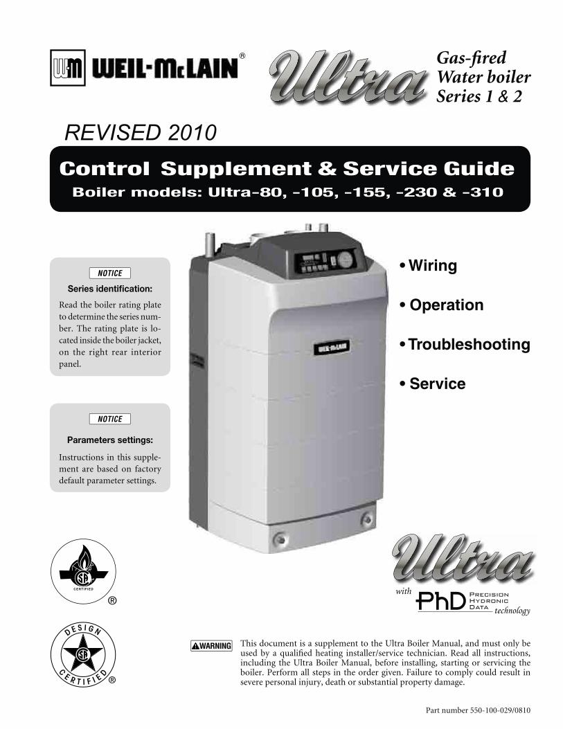
Read the boiler rating plate to determine the series num-ber. The rating plate is lo-cated inside the boiler jacket, on the right rear interior panel.
Parameters settings:
Instructions in this supple-ment are based on factory default parameter settings.
This document is a supplement to the Ultra Boiler Manual, and must only be used by a qualified heating installer/service technician. Read all instructions, including the Ultra Boiler Manual, before installing, starting or servicing the boiler. Perform all steps in the order given. Failure to comply could result in severe personal injury, death or substantial property damage.
with
Control Supplement & Service GuideBoiler models: Ultra-80, -105, -155, -230 & -310
Gas-firedWater boilerSeries 1 & 2
REVISED 2010
2 Part number 550-100-029/0810
GAS-FIRED WATER BOILER SERIES 1 & 2 — Control supplement & Service guide
Contents
3
3
4
6
9
22
33
38
41
42
44
50
3Part number 550-100-029/0810
GAS-FIRED WATER BOILER SERIES 1 & 2 — Control supplement & Service guide
Please read before proceeding
When servicing boiler —
To avoid electric shock, disconnect electrical supply
before performing maintenance.
To avoid severe burns, allow boiler to cool before per-
forming maintenance.
Failure to adhere to the guidelines on this page can
result in severe personal injury, death or substantial
property damage.
Commonwealth of Massachusetts
When the boiler is installed within the Commonwealth
of Massachusetts:
This product must be installed by a licensed plumber
or gas fitter.
If antifreeze is used, a reduced pressure back-flow
preventer device shall be used.
High altitude installations
The boiler must be modified according to the procedure in the High altitude instructions. The minimum fanspeed and ignition fanspeed must be set on the Ultra Control module following the High altitude instructions (also included in this document, beginning on page 47).
— Read all instructions, including this manual, Ultra Boiler Manual, and the Ultra Vent Supplement, before installing. Perform steps in the order given.
— This document is for use only by a quali-fied heating installer/service technician.
— Have this boiler serviced/inspected by a qualified service technician, at least annually. Refer to User’s Information Manual for your reference.
Failure to comply with the above could result in severe personal injury, death or substantial property damage.
When calling or writing about the boiler — Please have the boiler model number from the boiler rat-ing label and the CP number from the boiler jacket. You may list the CP number in the space provided on the Installation and service certificate found in the Ultra Boiler Manual.
Consider piping and installation when determining boiler location.
The following defined terms are used throughout this manual to
bring attention to the presence of hazards of various risk levels or
to important information concerning the life of the product.
Indicates presence of hazards that will cause severe
personal injury, death or substantial property dam-
age.
Indicates presence of hazards that can cause severe
personal injury, death or substantial property dam-
age.
Indicates presence of hazards that will or can
cause minor personal injury or property damage.
Indicates special instructions on installation, op-
eration or maintenance that are important but not
related to personal injury or property damage.
Hazard definitions
4 Part number 550-100-029/0810
GAS-FIRED WATER BOILER SERIES 1 & 2 — Control supplement & Service guide
Field wiring
ELECTRICAL SHOCK HAZARD — For your safety, turn off electrical power supply at service entrance panel before making any electrical connections to avoid possible electric shock hazard. Failure to do so can cause severe personal injury or death.
Wiring must be N.E.C. Class 1. If origi-nal wiring as supplied with boiler must be replaced, use only type 105°C wire or equivalent. Boiler must be electri-cally grounded as required by National Electrical Code ANSI/NFPA 70 – latest edition.
Install field wiring before venting to allow easier access to terminal strips.
Installation must comply with:1. National Electrical Code and any other national, state,
provincial or local codes or regulations.
2. In Canada, CSA C22.1 Canadian Electrical Code Part 1, and any local codes.
Line voltage connections1. Connect 120 VAC power wiring to line voltage terminal
strip in left compartment of electrical entrance, as shown in Figure 2, page 5, item 1.
2. Provide and install a fused disconnect or service switch (15 amp. recommended) as required by the code. (See
Figure 2, page 5, item 2)
3. Boiler circulator is shipped loose. Wire Boiler circulator as shown for Fig-ure 2, page 5, item 3.
4. When connecting a DHW circulator, connect wiring to line voltage terminal strip as shown for Figure 2, page 5, item 5.
5. Route all wires and conduits to the jacket openings specified in Figure 1.
Wiring a system circulator1. To activate a system circulator when the Boiler circulator operates, add a cir-
culator relay and wire as shown in Figure 2, page 5.
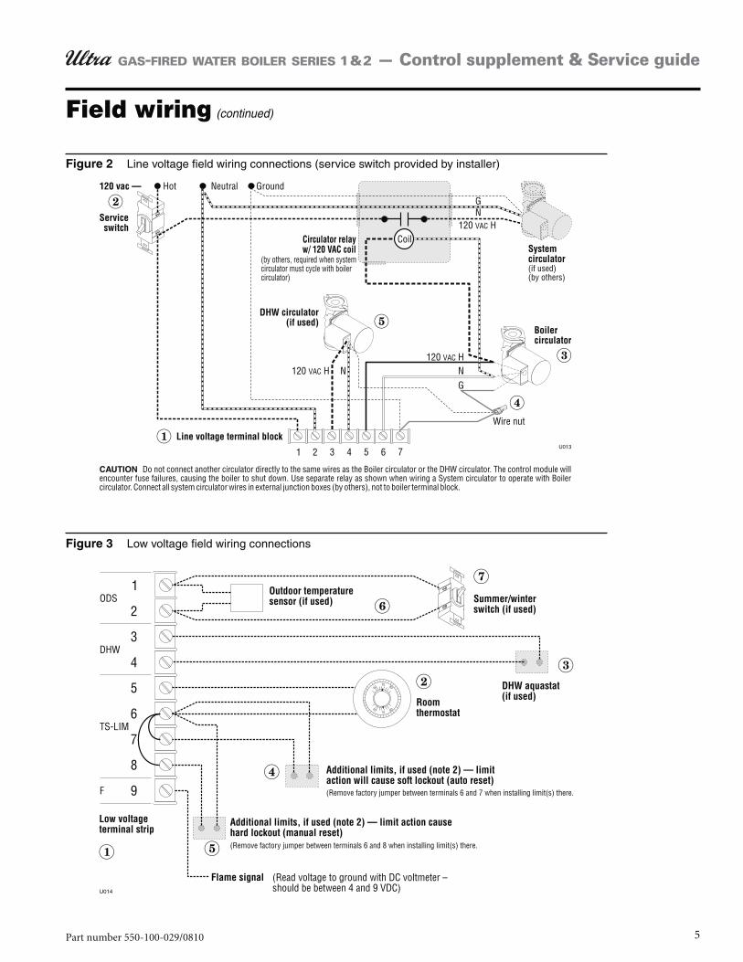
2. You must install a relay as shown. DO NOT wire in parallel with the Boiler circulator. See CAUTION in Figure 2, page 5.
Low voltage connections1. Connect low voltage wiring to low voltage terminal strip (Figure 3, page 5,
item 1) as shown in Figure 3 and the boiler wiring diagram.
2. Route all low voltage wires through grommeted jacket opening to right of low voltage terminal strip, as shown in Figure 1.
Thermostat1. Connect Figure 3, page 5, item 2, room thermostat or end switch (isolated
contact only) between terminals 5 and 6.
2. Install thermostat on inside wall away from influences of drafts, hot or cold water pipes, lighting fixtures, television, sun rays, or fireplaces.
3. Thermostat anticipator (if applicable):If connected directly to boiler, set for 0.1 amps.a. If connected to relays or other devices, set to match total electrical power b. requirements of connected devices. See device manufacturers’ specifications and thermostat instructions for details.
Outdoor temperature sensor1. Connect outdoor temperature sensor (Figure 3, page 5, item 6) between ter-
minals 1 and 2 to enable outdoor reset operation of the Ultra boiler. If fixed-temperature operation is required, do not install outdoor sensor.
2. Mount sensor on an exterior wall, if possible the North wall, shielded from direct sunlight or flow of heat or cooling from other sources.
3. If desired, install a summer/winter switch (Figure 3, page 5, item 7) across ter-minals 1 and 2. When the switch is closed, the boiler (space heating) circulator is disabled.
4. Route sensor wires through the hole at the right of the electrical entrance (see Figure 1).
DHW aquastat1. Connect storage indirect water heater (DHW) aquastat (Figure 3, page 5, item 3)
between terminals 3 and 4.
Additional limits1. Connect additional limit controls and interlocks between the terminals shown
in Figure 3, page 5.
2. Controls connected between terminals 6 and 7 (see Figure 3, page 5, item 4) will cause a soft lockout (automatic reset). When limit(s) closes, boiler will resume normal operation.
3. Controls connected between terminals 6 and 8 (see Figure 3, page 5, item 5) will cause a hard lockout (manual reset). The boiler will only restart after the Ultra display panel RESET switch is pressed.
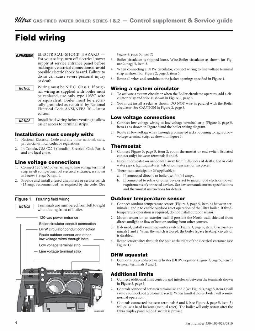
Routing field wiring
Terminals are numbered from left to right when facing front of boiler.
5Part number 550-100-029/0810
GAS-FIRED WATER BOILER SERIES 1 & 2 — Control supplement & Service guide
Field wiring (continued)
Line voltage field wiring connections (service switch provided by installer)
Low voltage field wiring connections
6 Part number 550-100-029/0810
GAS-FIRED WATER BOILER SERIES 1 & 2 — Control supplement & Service guide
Startup
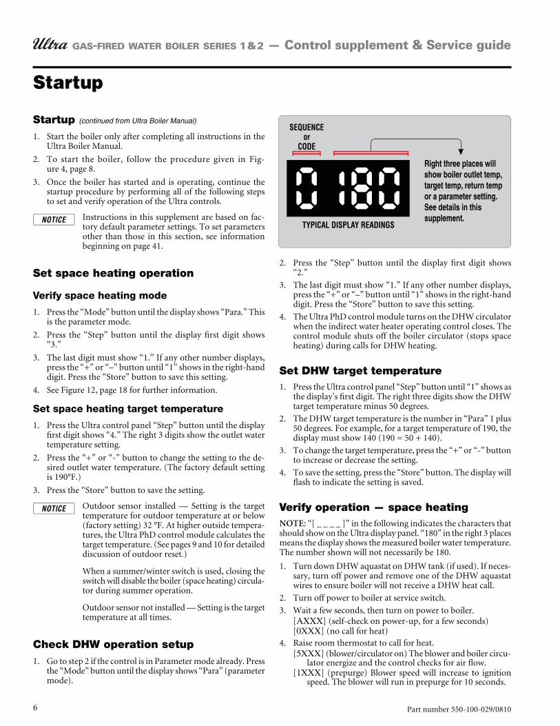
Press the “Step” button until the display first digit shows 2. “2.”
The last digit must show “1.” If any other number displays, 3. press the “+” or “–” button until “1” shows in the right-hand digit. Press the “Store” button to save this setting.
The Ultra PhD control module turns on the DHW circulator 4. when the indirect water heater operating control closes. The control module shuts off the boiler circulator (stops space heating) during calls for DHW heating.
Set DHW target temperaturePress the Ultra control panel “Step” button until “1” shows as 1. the display’s first digit. The right three digits show the DHW target temperature minus 50 degrees.
The DHW target temperature is the number in “Para” 1 plus 2. 50 degrees. For example, for a target temperature of 190, the display must show 140 (190 = 50 + 140).
To change the target temperature, press the “+” or “-” button 3. to increase or decrease the setting.
To save the setting, press the “Store” button. The display will 4. flash to indicate the setting is saved.
Verify operation — space heatingNOTE: “[ _ _ _ _ ]” in the following indicates the characters that should show on the Ultra display panel. “180” in the right 3 places means the display shows the measured boiler water temperature. The number shown will not necessarily be 180.
Turn down DHW aquastat on DHW tank (if used). If neces-1. sary, turn off power and remove one of the DHW aquastat wires to ensure boiler will not receive a DHW heat call.
Turn off power to boiler at service switch.2.
Wait a few seconds, then turn on power to boiler.3. [AXXX] (self-check on power-up, for a few seconds)[0XXX] (no call for heat)Raise room thermostat to call for heat.4. [5XXX] (blower/circulator on) The blower and boiler circu-
lator energize and the control checks for air flow.[1XXX] (prepurge) Blower speed will increase to ignition
speed. The blower will run in prepurge for 10 seconds.
Startup (continued from Ultra Boiler Manual)
Start the boiler only after completing all instructions in the 1. Ultra Boiler Manual.
To start the boiler, follow the procedure given in 2. Fig-ure 4, page 8.
Once the boiler has started and is operating, continue the 3. startup procedure by performing all of the following steps to set and verify operation of the Ultra controls.
Instructions in this supplement are based on fac-tory default parameter settings. To set parameters other than those in this section, see information beginning on page 41.
Set space heating operation
Verify space heating mode
Press the “Mode” button until the display shows “Para.” This 1. is the parameter mode.
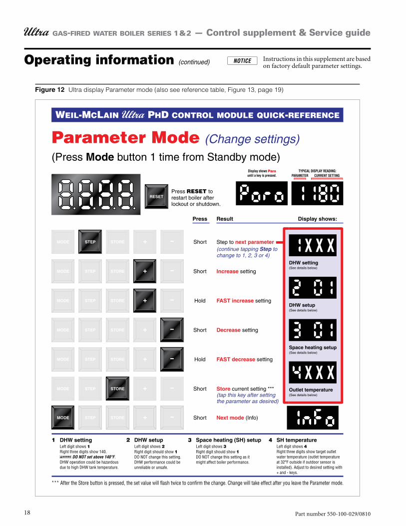
Press the “Step” button until the display first digit shows 2. “3.”
The last digit must show “1.” If any other number displays, 3. press the “+” or “–” button until “1” shows in the right-hand digit. Press the “Store” button to save this setting.
See 4. Figure 12, page 18 for further information.
Set space heating target temperature
Press the Ultra control panel “Step” button until the display 1. first digit shows “4.” The right 3 digits show the outlet water temperature setting.
Press the “+” or “-” button to change the setting to the de-2. sired outlet water temperature. (The factory default setting is 190°F.)
Press the “Store” button to save the setting.3.
Outdoor sensor installed — Setting is the target temperature for outdoor temperature at or below (factory setting) 32 °F. At higher outside tempera-tures, the Ultra PhD control module calculates the target temperature. (See pages 9 and 10 for detailed discussion of outdoor reset.)
When a summer/winter switch is used, closing the switch will disable the boiler (space heating) circula-tor during summer operation.
Outdoor sensor not installed — Setting is the target temperature at all times.
Check DHW operation setupGo to step 2 if the control is in Parameter mode already. Press 1. the “Mode” button until the display shows “Para” (parameter mode).
7Part number 550-100-029/0810
GAS-FIRED WATER BOILER SERIES 1 & 2 — Control supplement & Service guide
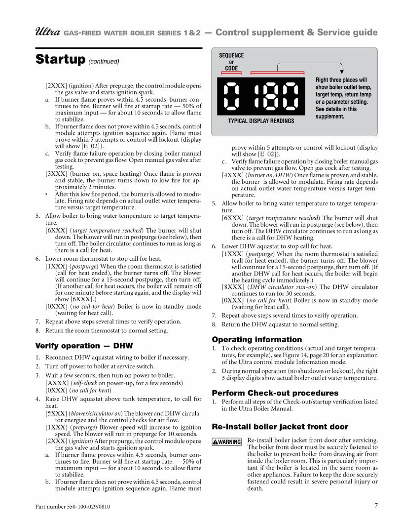
[2XXX] (ignition) After prepurge, the control module opens the gas valve and starts ignition spark.If burner flame proves within 4.5 seconds, burner con-a. tinues to fire. Burner will fire at startup rate — 50% of maximum input — for about 10 seconds to allow flame to stabilize.If burner flame does not prove within 4.5 seconds, control b. module attempts ignition sequence again. Flame must prove within 5 attempts or control will lockout (display will show [E 02]).Verify flame failure operation by closing boiler manual c. gas cock to prevent gas flow. Open manual gas valve after testing.
[3XXX] (burner on, space heating) Once flame is proven and stable, the burner turns down to low fire for ap-proximately 2 minutes.After this low fire period, the burner is allowed to modu-late. Firing rate depends on actual outlet water tempera-ture versus target temperature.
Allow boiler to bring water temperature to target tempera-5. ture. [6XXX] (target temperature reached) The burner will shut
down. The blower will run in postpurge (see below), then turn off. The boiler circulator continues to run as long as there is a call for heat.
Lower room thermostat to stop call for heat.6. [1XXX] (postpurge) When the room thermostat is satisfied
(call for heat ended), the burner turns off. The blower will continue for a 15-second postpurge, then turn off. (If another call for heat occurs, the boiler will remain off for one minute before starting again, and the display will show [6XXX].)
[0XXX] (no call for heat) Boiler is now in standby mode (waiting for heat call).
Repeat above steps several times to verify operation.7.
Return the room thermostat to normal setting.8.
Verify operation — DHWReconnect DHW aquastat wiring to boiler if necessary.1.
Turn off power to boiler at service switch.2.
Wait a few seconds, then turn on power to boiler.3. [AXXX] (self-check on power-up, for a few seconds)[0XXX] (no call for heat)Raise DHW aquastat above tank temperature, to call for 4. heat.[5XXX] (blower/circulator on) The blower and DHW circula-
tor energize and the control checks for air flow.[1XXX] (prepurge) Blower speed will increase to ignition
speed. The blower will run in prepurge for 10 seconds. [2XXX] (ignition) After prepurge, the control module opens
the gas valve and starts ignition spark.If burner flame proves within 4.5 seconds, burner con-a. tinues to fire. Burner will fire at startup rate — 50% of maximum input — for about 10 seconds to allow flame to stabilize.If burner flame does not prove within 4.5 seconds, control b. module attempts ignition sequence again. Flame must
prove within 5 attempts or control will lockout (display will show [E 02]).Verify flame failure operation by closing boiler manual gas c. valve to prevent gas flow. Open gas cock after testing.
[4XXX] (burner on, DHW) Once flame is proven and stable, the burner is allowed to modulate. Firing rate depends on actual outlet water temperature versus target tem-perature.
Allow boiler to bring water temperature to target tempera-5. ture. [6XXX] (target temperature reached) The burner will shut
down. The blower will run in postpurge (see below), then turn off. The DHW circulator continues to run as long as there is a call for DHW heating.
Lower DHW aquastat to stop call for heat.6. [1XXX] (postpurge) When the room thermostat is satisfied
(call for heat ended), the burner turns off. The blower will continue for a 15-second postpurge, then turn off. (If another DHW call for heat occurs, the boiler will begin the heating cycle immediately.)
[8XXX] (DHW circulator run-on) The DHW circulator continues to run for 30 seconds.
[0XXX] (no call for heat) Boiler is now in standby mode (waiting for heat call).
Repeat above steps several times to verify operation.7.
Return the DHW aquastat to normal setting.8.
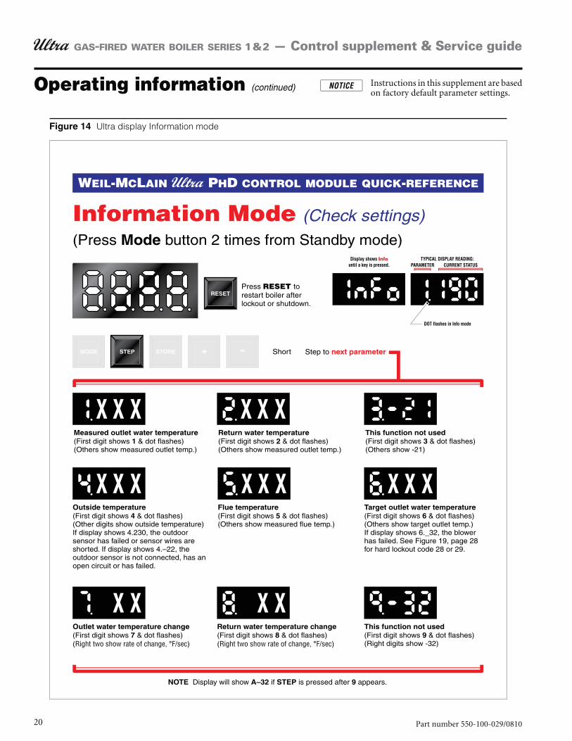
Operating informationTo check operating conditions (actual and target tempera-1. tures, for example), see Figure 14, page 20 for an explanation of the Ultra control module Information mode.
During normal operation (no shutdown or lockout), the right 2. 3 display digits show actual boiler outlet water temperature.
Perform Check-out proceduresPerform all steps of the Check-out/startup verification listed 1. in the Ultra Boiler Manual.
Re-install boiler jacket front door
Re-install boiler jacket front door after servicing. The boiler front door must be securely fastened to the boiler to prevent boiler from drawing air from inside the boiler room. This is particularly impor-tant if the boiler is located in the same room as other appliances. Failure to keep the door securely fastened could result in severe personal injury or death.
Startup (continued)
8 Part number 550-100-029/0810
GAS-FIRED WATER BOILER SERIES 1 & 2 — Control supplement & Service guide
Startup (continued)
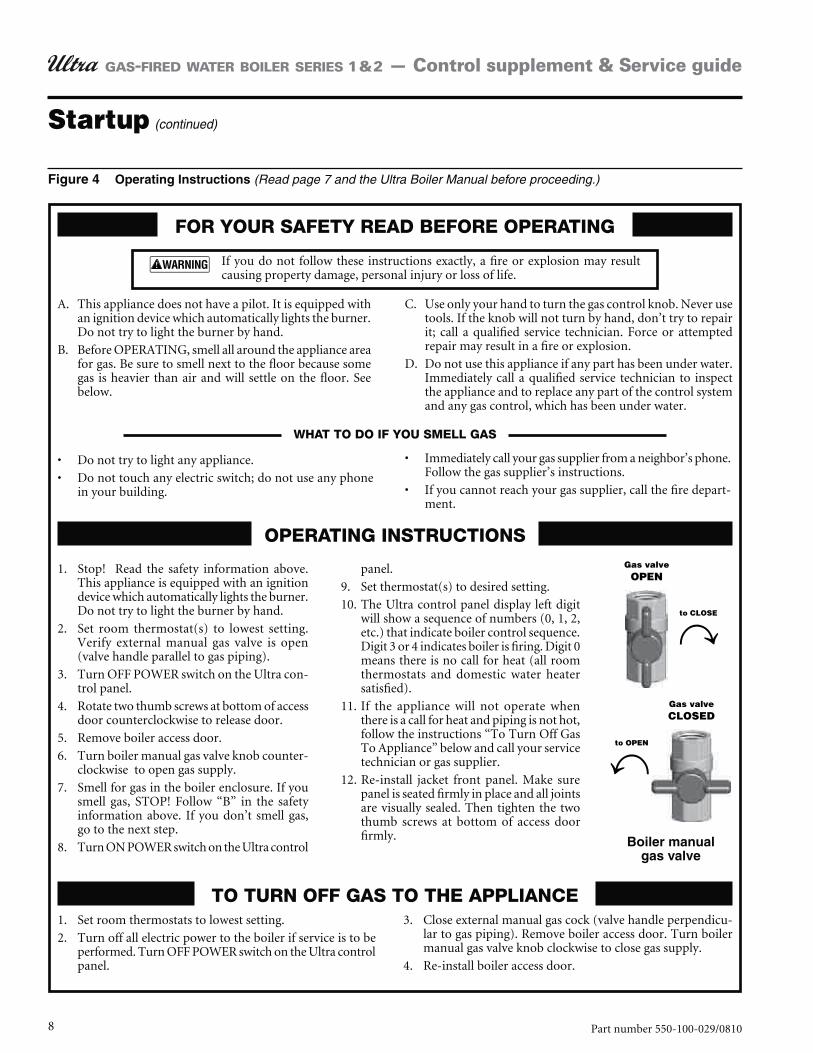
FOR YOUR SAFETY READ BEFORE OPERATING
OPERATING INSTRUCTIONS
TO TURN OFF GAS TO THE APPLIANCE
in your building.
Follow the gas supplier’s instructions.
-ment.
WHAT TO DO IF YOU SMELL GAS
A. This appliance does not have a pilot. It is equipped with an ignition device which automatically lights the burner. Do not try to light the burner by hand.
B. Before OPERATING, smell all around the appliance area for gas. Be sure to smell next to the floor because some gas is heavier than air and will settle on the floor. See below.
C. Use only your hand to turn the gas control knob. Never use tools. If the knob will not turn by hand, don’t try to repair
repair may result in a fire or explosion.
D. Do not use this appliance if any part has been under water. Immediately call a qualified service technician to inspect the appliance and to replace any part of the control system and any gas control, which has been under water.
If you do not follow these instructions exactly, a fire or explosion may result causing property damage, personal injury or loss of life.
(Read page 7 and the Ultra Boiler Manual before proceeding.)
1. Stop! Read the safety information above. This appliance is equipped with an ignition device which automatically lights the burner. Do not try to light the burner by hand.
2. Set room thermostat(s) to lowest setting. Verify external manual gas valve is open (valve handle parallel to gas piping).
3. Turn OFF POWER switch on the Ultra con-trol panel.
4. Rotate two thumb screws at bottom of access door counterclockwise to release door.
5. Remove boiler access door.
6. Turn boiler manual gas valve knob counter-clockwise to open gas supply.
7. Smell for gas in the boiler enclosure. If you smell gas, STOP! Follow “B” in the safety information above. If you don’t smell gas, go to the next step.
8. Turn ON POWER switch on the Ultra control
panel.
9. Set thermostat(s) to desired setting.
10. The Ultra control panel display left digit will show a sequence of numbers (0, 1, 2, etc.) that indicate boiler control sequence. Digit 3 or 4 indicates boiler is firing. Digit 0 means there is no call for heat (all room thermostats and domestic water heater satisfied).
11. If the appliance will not operate when there is a call for heat and piping is not hot, follow the instructions “To Turn Off Gas To Appliance” below and call your service technician or gas supplier.
12. Re-install jacket front panel. Make sure panel is seated firmly in place and all joints are visually sealed. Then tighten the two thumb screws at bottom of access door firmly.
1. Set room thermostats to lowest setting.
2. Turn off all electric power to the boiler if service is to be performed. Turn OFF POWER switch on the Ultra control panel.
3. Close external manual gas cock (valve handle perpendicu-lar to gas piping). Remove boiler access door. Turn boiler manual gas valve knob clockwise to close gas supply.
4. Re-install boiler access door.
9Part number 550-100-029/0810
GAS-FIRED WATER BOILER SERIES 1 & 2 — Control supplement & Service guide
Operating information
Ultra Control Module
The Ultra boiler is controlled by a microprocessor electronic con-trol — the Ultra Control Module. The module senses outlet water temperature, return water temperature, flue temperature and outdoor temperature (when outdoor sensor is installed). It uses this information (plus input from external limit and operat-ing controls) to regulate boiler on/off operation and can modulate boiler firing rate to more closely match output to demand.
Electrical specifications
Ultra boilers require 120 VAC/60 HZ power supply and are polar-ity sensitive.
Control module specifications
Boiler temperature regulation
Operating temperature (target)
The Ultra control module senses outlet water temperature and regulates boiler firing rate to achieve a target temperature, set by installer, by setting Parameter 4. Temperature can be set between 70°F and 190°F. See page 18 for procedure.
Space heating with fixed temperature — Target temperature is fixed (equal to Parameter 4) when outdoor reset is not installed.
Space heating with outdoor reset — Target temperature is calculated as described under “Outdoor reset operation” when outdoor sensor is connected. Exception: See explanation of “Supply temperature boost.”
DHW heating — Target temperature is 50°F + Parameter 1. Do not change parameter 1 from the factory default setting of 140°F unless the application is specially engineered for other temperature.
High limit operation
If outlet water temperature exceeds target temperature plus OFF differential (or 190°F plus OFF differential, whichever is lower), high limit action occurs. The control module shuts the burner off.
DHW operation (if used)
The boiler is factory set to immediately change target outlet water temperature to 190°F on a call for heat from the DHW aquastat.
Additional Thermal Overrun Protection
High limit operation shuts down the burner when the outlet water temperature exceeds the target temperature. However, adverse conditions could cause the water temperature to rise too quickly, overshooting this temperature. The Ultra control module’s technology provides advanced protection in the event of thermal overrun. Using its electronics, the Ultra control module provides two additional levels of overrun protection:
Indication would occur if supply or return water temperature reached 203°F. The Ultra control module would display a soft lockout code (“b” followed by “18” if on the supply, or “19” if on the return). The module would not operate the burner again until the water temperature dropped 9°F below target temperature.
Lockout would occur if supply or return water tempera-ture reached 210°F. The Ultra module would enter hard lockout and display an error code (“E” followed by “18” if on the supply or “19” if on the return). NOTE: Hard lockout requires manually pressing the Ultra display panel reset button to restart operation. Service techni-cian must troubleshoot the cause of the problem and correct it before placing the boiler back in operation.
Low water protection
The control module uses temperatures sensed at both supply 1. and return areas of the heat exchanger. If the flow rate is too low (temperature difference too high) or either temperature is too high, the control module shuts the boiler down. This ensures boiler shutdown in the event of low water or low flow conditions.
Some codes and jurisdiction may accept these integral features 2. of the control in lieu of requiring an additional limit control or low water cutoff. Consult local jurisdiction to determine.
10 Part number 550-100-029/0810
GAS-FIRED WATER BOILER SERIES 1 & 2 — Control supplement & Service guide
Operating information (continued)
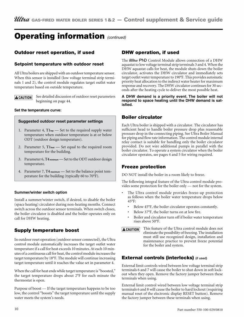
Outdoor reset operation, if used
Setpoint temperature with outdoor reset
All Ultra boilers are shipped with an outdoor temperature sensor. When this sensor is installed (low voltage terminal strip termi-nals 1 and 2), the control module regulates target outlet water temperature based on outside temperature.
See detailed discussion of outdoor reset parameters beginning on page 44.
Suggested outdoor reset parameter settings
Parameter 4, 1. T1 — Set to the required supply water temperature when outdoor temperature is at or below ODT (outdoor design temperature).
Parameter 5, 2. T1 — Set equal to the required room temperature for the building.
Parameter 6, 3. T4 — Set to the ODT outdoor design temperature.
Parameter 7, 4. T4 — Set to the balance point tem-perature for the building (typically 60 to 70°F).
Install a summer/winter switch, if desired, to disable the boiler (space heating) circulator during non-heating months. Connect switch across the outdoor sensor terminals. When switch closes, the boiler circulator is disabled and the boiler operates only on call for DHW heating.
Supply temperature boost
In outdoor reset operation (outdoor sensor connected), the Ultra control module automatically increases the target outlet water temperature if a call for heat exceeds 10 minutes. At each 10 min-utes of a continuous call for heat, the control module increases the target temperature by 18°F. The module will continue increasing target temperature until it reaches the value set in parameter 4.
When the call for heat ends while target temperature is “boosted,” the target temperature drops about 2°F for each minute the thermostat is open.
Purpose of boost — If the target temperature happens to be too low, the control “boosts” the target temperature until the supply water meets the system’s needs.
DHW operation, if used
The PhD Control Module allows connection of a DHW aquastat to low voltage terminal strip terminals 3 and 4. When the DHW aquastat calls for heat, the module shuts down the boiler circulator, activates the DHW circulator and immediately sets target outlet water temperature to 190°F. This provides automatic priority heat allocation to the indirect water heater for maximum response and recovery. The DHW circulator continues for 30 sec-onds after the heating cycle to deliver the most possible heat.
-
Boiler circulator
Each Ultra boiler is shipped with a circulator. The circulator has sufficient head to handle boiler pressure drop plus reasonable pressure drop in the connecting piping. See Ultra Boiler Manual for piping and flow rate information. The control module internal relay contact is suitable for handling only the boiler circulator provided. Do not wire additional pumps in parallel with the boiler circulator. To operate a system circulator when the boiler circulator operates, see pages 4 and 5 for wiring required.
Freeze protection
DO NOT install the boiler in a room likely to freeze.
The following integral feature of the Ultra control module pro-vides some protection for the boiler only — not for the system.
The Ultra control module provides freeze-up protection as follows when the boiler water temperature drops below 45°F:
Below 45°F, the boiler circulator operates constantly.Below 37°F, the boiler turns on at low fire.Boiler and circulator turn off if boiler water temperature rises above 50°F.
This feature of the Ultra control module does not eliminate the possibility of freezing. The installation must still use recognized design, installation and maintenance practice to prevent freeze potential for the boiler and system.
External controls (interlocks) (if used)
External limit controls wired between low voltage terminal strip terminals 6 and 7 will cause the boiler to shut down in soft lock-out when they open. Remove the factory jumper between these terminals when using.
External limit control wired between low voltage terminal strip terminals 6 and 8 will cause the boiler to hard lockout (requiring manual reset of the electronic display RESET button). Remove the factory jumper between these terminals when using.
11Part number 550-100-029/0810
GAS-FIRED WATER BOILER SERIES 1 & 2 — Control supplement & Service guide
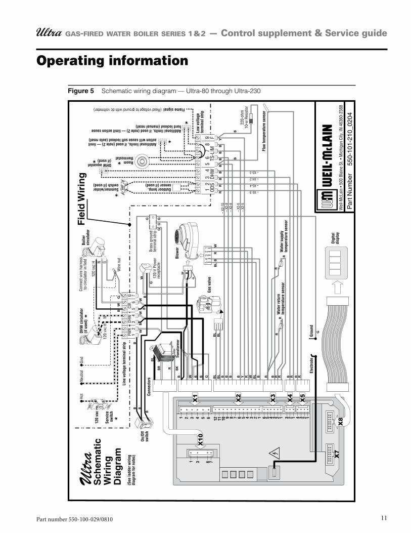
Schematic wiring diagram — Ultra-80 through Ultra-230
Operating information
12 Part number 550-100-029/0810
GAS-FIRED WATER BOILER SERIES 1 & 2 — Control supplement & Service guide
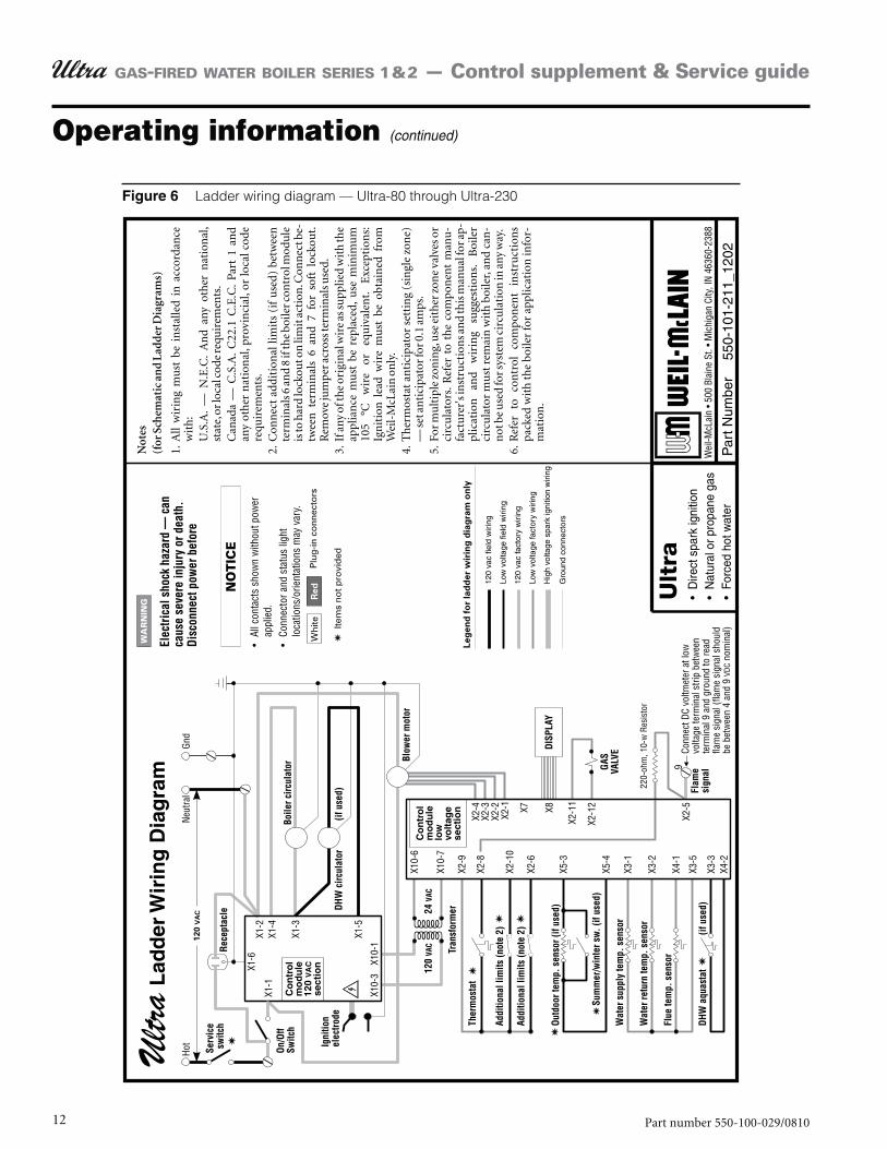
Ladder wiring diagram — Ultra-80 through Ultra-230
Operating information (continued)
13Part number 550-100-029/0810
GAS-FIRED WATER BOILER SERIES 1 & 2 — Control supplement & Service guide
Operating information (continued)
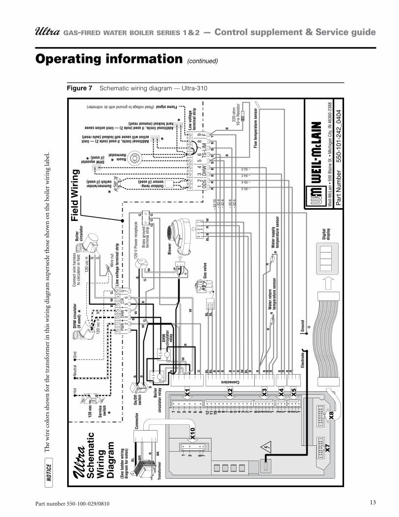
Schematic wiring diagram — Ultra-310
T
he
wir
e co
lors
sh
own
for
the
tran
sfor
mer
in t
his
wir
ing
diag
ram
su
pers
ede
thos
e sh
own
on
th
e bo
iler
wir
ing
labe
l.
14 Part number 550-100-029/0810
GAS-FIRED WATER BOILER SERIES 1 & 2 — Control supplement & Service guide
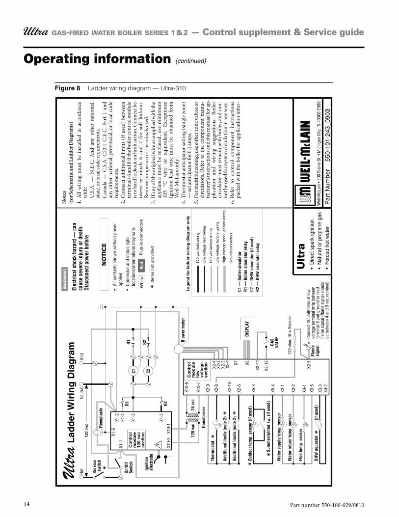
Ladder wiring diagram — Ultra-310
Operating information (continued)
15Part number 550-100-029/0810
GAS-FIRED WATER BOILER SERIES 1 & 2 — Control supplement & Service guide
Operating information (continued)
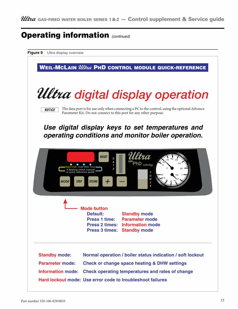
Ultra display overview
The data port is for use only when connecting a PC to the control, using the optional Advance Parameter Kit. Do not connect to this port for any other purpose.
16 Part number 550-100-029/0810
GAS-FIRED WATER BOILER SERIES 1 & 2 — Control supplement & Service guide
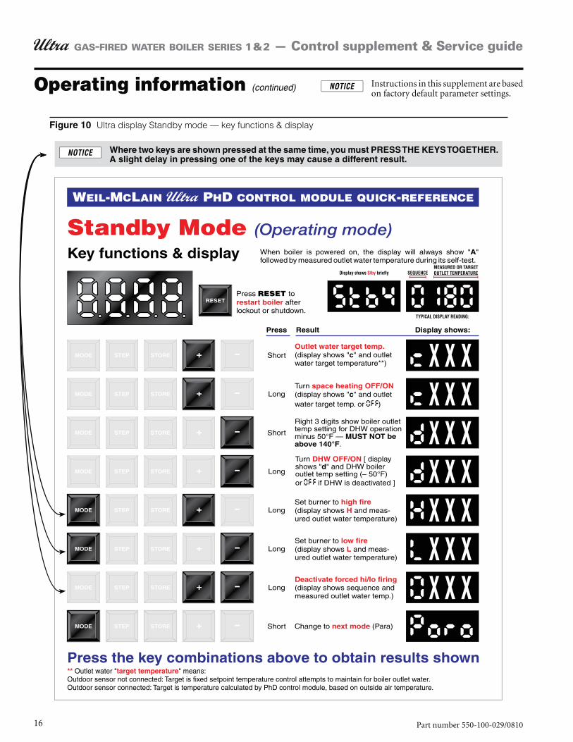
Operating information (continued) Instructions in this supplement are based on factory default parameter settings.
Ultra display Standby mode — key functions & display
17Part number 550-100-029/0810
GAS-FIRED WATER BOILER SERIES 1 & 2 — Control supplement & Service guide
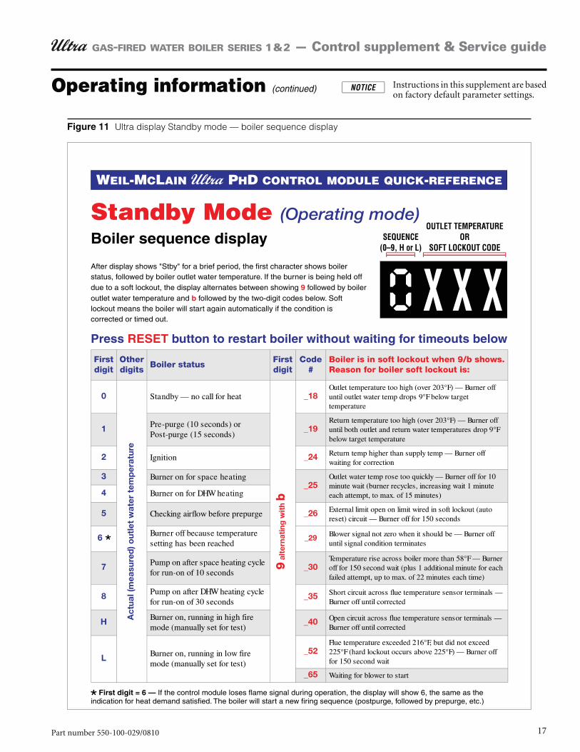
Operating information (continued) Instructions in this supplement are based on factory default parameter settings.
Ultra display Standby mode — boiler sequence display
18 Part number 550-100-029/0810
GAS-FIRED WATER BOILER SERIES 1 & 2 — Control supplement & Service guide
Operating information (continued) Instructions in this supplement are based on factory default parameter settings.
Ultra display Parameter mode (also see reference table, Figure 13, page 19)
19Part number 550-100-029/0810
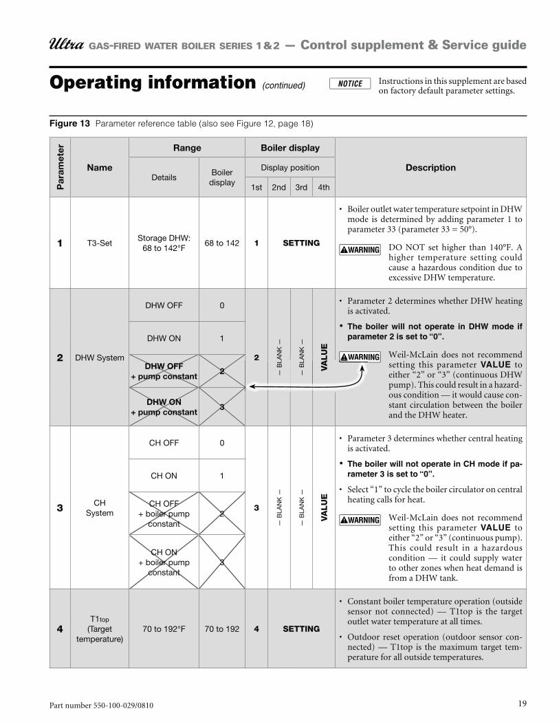
GAS-FIRED WATER BOILER SERIES 1 & 2 — Control supplement & Service guide
Operating information (continued) Instructions in this supplement are based on factory default parameter settings.
Par
amet
er
Name
Range Boiler display
DescriptionDetails
Boiler display
Display position
1st 2nd 3rd 4th
1 T3-SetStorage DHW:
68 to 142°F68 to 142 1 SETTING
Boiler outlet water temperature setpoint in DHW mode is determined by adding parameter 1 to parameter 33 (parameter 33 = 50°).
DO NOT set higher than 140°F. A higher temperature setting could cause a hazardous condition due to excessive DHW temperature.
2 DHW System
DHW OFF 0
2
— B
LAN
K —
— B
LAN
K —
VA
LU
E
Parameter 2 determines whether DHW heating is activated.
•
Weil-McLain does not recommend setting this parameter to either “2” or “3” (continuous DHW pump). This could result in a hazard-ous condition — it would cause con-stant circulation between the boiler and the DHW heater.
DHW ON 1
DHW OFF + pump constant
2
DHW ON + pump constant
3
3 CH System
CH OFF 0
3
— B
LAN
K —
— B
LAN
K —
VA
LU
E
Parameter 3 determines whether central heating is activated.
-•
Select “1” to cycle the boiler circulator on central heating calls for heat.
Weil-McLain does not recommend setting this parameter to either “2” or “3” (continuous pump). This could result in a hazardous condition — it could supply water to other zones when heat demand is from a DHW tank.
CH ON 1
CH OFF + boiler pump
constant2
CH ON + boiler pump
constant3
4T1top
(Target temperature)
70 to 192°F 70 to 192 4 SETTING
Constant boiler temperature operation (outside sensor not connected) — T1top is the target outlet water temperature at all times.
Outdoor reset operation (outdoor sensor con-nected) — T1top is the maximum target tem-perature for all outside temperatures.
Parameter reference table (also see Figure 12, page 18)
2
— B
L
— B
L
VA
20 Part number 550-100-029/0810
GAS-FIRED WATER BOILER SERIES 1 & 2 — Control supplement & Service guide
Operating information (continued) Instructions in this supplement are based on factory default parameter settings.
Ultra display Information mode
21Part number 550-100-029/0810
GAS-FIRED WATER BOILER SERIES 1 & 2 — Control supplement & Service guide
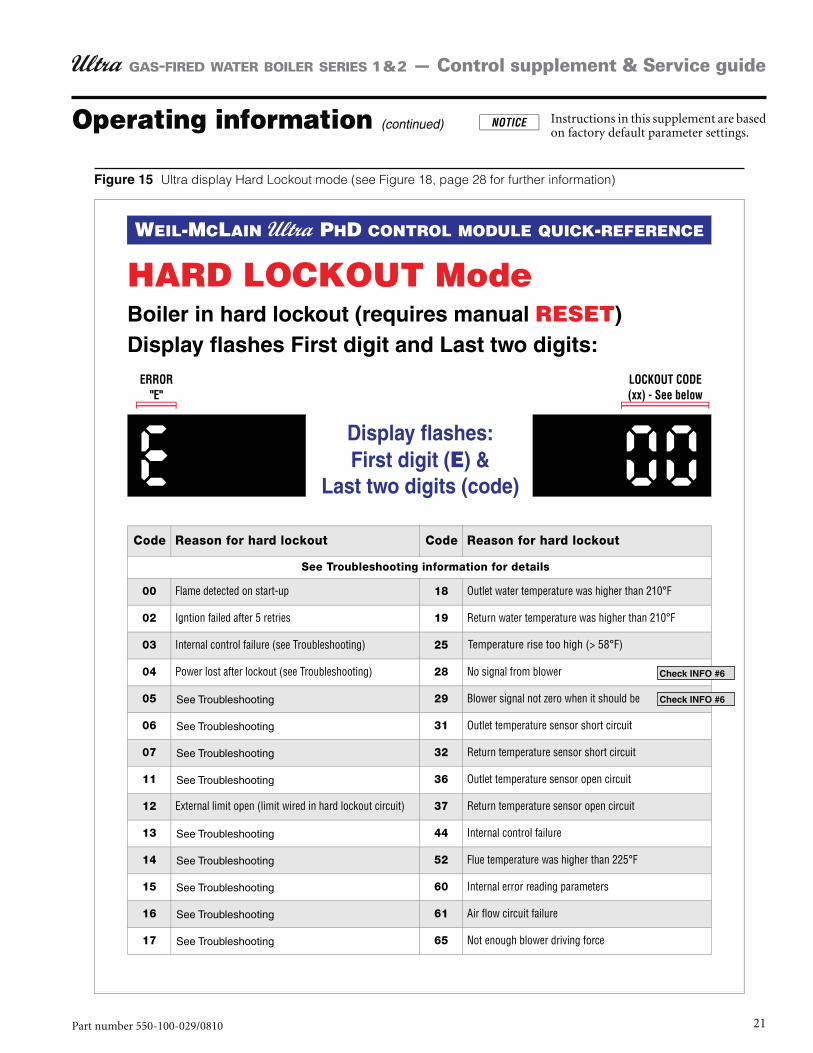
Operating information (continued) Instructions in this supplement are based on factory default parameter settings.
Ultra display Hard Lockout mode (see Figure 18, page 28 for further information)
22 Part number 550-100-029/0810
GAS-FIRED WATER BOILER SERIES 1 & 2 — Control supplement & Service guide
VERIFY PROPER OPERATION AFTER SERVICING (see Ultra Boiler Manual for procedures)
Troubleshooting
prior to disconnection when servicing controls. Wiring errors can cause improper and dangerous opera-tion. Always disconnect power to boiler before servicing. Failure to comply could result in severe personal injury, death or substantial property damage.
ex-cept for momentary testing as outlined in Troubleshooting tables. Severe personal injury, death or substantial property dam-age can result.
Before troubleshooting:Have the following items:1.
Voltmeter that can check 120 VAC , 24 VAC and a. 12 VDC.Continuity checker.b. Contact thermometer.c.
Check for 120 VAC (minimum 102 VAC to maxi-2. mum 132 VAC) to boiler.
Make sure thermostat is calling for heat and contacts 3. (including appropriate zone controls) are closed. Check for 24 VAC between thermostat wire nuts and ground.
Make sure all external limit controls are either 4. installed (and closed) or temporarily jumpered for testing.
Check the following:Wire connectors to control module are securely 1. plugged in at module and originating control.
Gas pressures:2. Maximum: 13” w.c. with no flow (lockup) or with boiler onMinimum: 5” w.c. with gas flowing (verify dur-ing boiler startup with boiler at high fire)
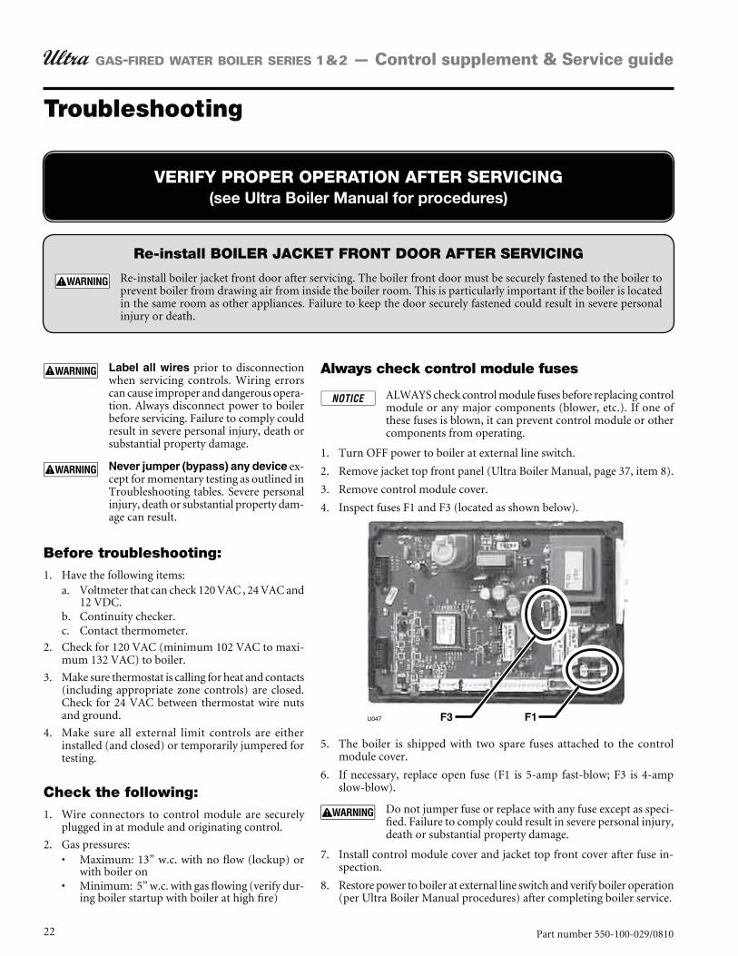
Always check control module fuses
ALWAYS check control module fuses before replacing control module or any major components (blower, etc.). If one of these fuses is blown, it can prevent control module or other components from operating.
Turn OFF power to boiler at external line switch.1.
Remove jacket top front panel (Ultra Boiler Manual, page 37, item 8).2.
Remove control module cover.3.
Inspect fuses F1 and F3 (located as shown below).4.
The boiler is shipped with two spare fuses attached to the control 5. module cover.
6. slow-blow).
Do not jumper fuse or replace with any fuse except as speci-fied. Failure to comply could result in severe personal injury, death or substantial property damage.
Install control module cover and jacket top front cover after fuse in-7. spection.
Restore power to boiler at external line switch and verify boiler operation 8. (per Ultra Boiler Manual procedures) after completing boiler service.
Re-install BOILER JACKET FRONT DOOR AFTER SERVICING
Re-install boiler jacket front door after servicing. The boiler front door must be securely fastened to the boiler to prevent boiler from drawing air from inside the boiler room. This is particularly important if the boiler is located in the same room as other appliances. Failure to keep the door securely fastened could result in severe personal injury or death.
23Part number 550-100-029/0810
GAS-FIRED WATER BOILER SERIES 1 & 2 — Control supplement & Service guide
REVIEW OF LAST LOCKOUT CODE MESSAGE
To access parameters, view RPM speed and the last Error Code:The boiler must be in “STBY” mode.1.
Press and hold the STEP button.2.
While holding STEP, press and hold the MODE button.3.
Hold both buttons until CODE appears on the display. Release both buttons.4.
Press the STEP button and a number will appear as C-**.5.
Press the “+” or “–” buttons until the number changes to C-05.6.
Press STORE. The display should blink one time.7.
The control is now unlocked, ready to make parameter changes, view RPM speed and view the last error code.8.
To view the last lockout code:Press MODE until ERROR appears on the display, with the following information:
1.
The sequence when lockout occurred (example: 03 call for heat) 2.
Supply temperature at the time of lockout.3.
The return temperature at the time of lockout.4.
5.
Outdoor sensor status temperature if connected, –22 if not.6.
Troubleshooting (continued)
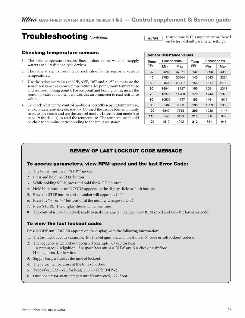
Checking temperature sensors
The boiler temperature sensors (flue, outdoor, return water and supply 1. water) are all resistance-type devices.
The table at right shows the correct value for the sensor at various 2. temperatures.
Use the resistance values at 32°F, 60°F, 70°F and 212°F to measure the 3. sensor resistance at known temperatures (ice point, room temperature and sea level boiling point). For ice point and boiling point, insert the sensor in water at that temperature. Use an ohmmeter to read resistance value.
To check whether the control module is correctly sensing temperature, 4. you can use a resistance decade box. Connect the decade box temporarily in place of a sensor and use the control module Information mode (see page 19 for details) to read the temperature. The temperature should be close to the value corresponding to the input resistance.
Sensor resistance values
Temp (°F)
Sensor ohms Temp (°F)
Sensor ohms
Min Max Min Max
32 34265 37871 130 3698 4088
40 27834 30764 140 3043 3364
50 21630 23907 150 2517 2782
60 16944 18727 160 2091 2311
13372 14780 1744 1928
80 10629 11747 180 1461 1615
90 8504 9399 190 1229 1359
100 6847 7568 200 1038 1147
110 5545 6129 210 880 972
120 4517 4992 212 851 941
Instructions in this supplement are based on factory default parameter settings.
24 Part number 550-100-029/0810
GAS-FIRED WATER BOILER SERIES 1 & 2 — Control supplement & Service guide
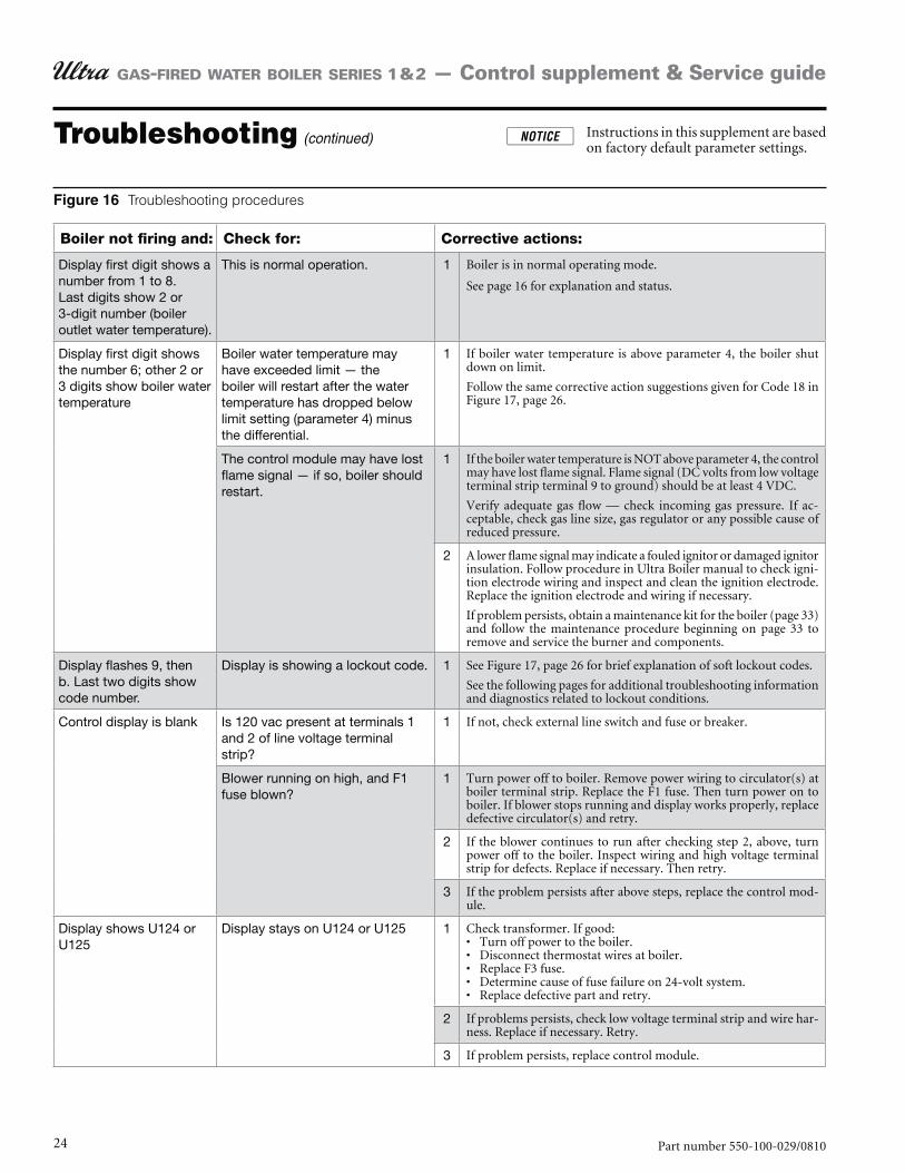
Boiler not firing and: Check for: Corrective actions:
Display first digit shows a number from 1 to 8.Last digits show 2 or 3-digit number (boiler outlet water temperature).
This is normal operation. 1 Boiler is in normal operating mode.
See page 16 for explanation and status.
Display first digit shows the number 6; other 2 or 3 digits show boiler water temperature
Boiler water temperature may have exceeded limit — the boiler will restart after the water temperature has dropped below limit setting (parameter 4) minus the differential.
1 If boiler water temperature is above parameter 4, the boiler shut down on limit.
Follow the same corrective action suggestions given for Code 18 in Figure 17, page 26.
The control module may have lost flame signal — if so, boiler should restart.
1 If the boiler water temperature is NOT above parameter 4, the control may have lost flame signal. Flame signal (DC volts from low voltage terminal strip terminal 9 to ground) should be at least 4 VDC.
Verify adequate gas flow — check incoming gas pressure. If ac-ceptable, check gas line size, gas regulator or any possible cause of reduced pressure.
2 A lower flame signal may indicate a fouled ignitor or damaged ignitor insulation. Follow procedure in Ultra Boiler manual to check igni-tion electrode wiring and inspect and clean the ignition electrode. Replace the ignition electrode and wiring if necessary.
If problem persists, obtain a maintenance kit for the boiler (page 33) and follow the maintenance procedure beginning on page 33 to remove and service the burner and components.
Display flashes 9, then b. Last two digits show code number.
Display is showing a lockout code. 1 See Figure 17, page 26 for brief explanation of soft lockout codes.
See the following pages for additional troubleshooting information and diagnostics related to lockout conditions.
Control display is blank Is 120 vac present at terminals 1 and 2 of line voltage terminal strip?
1 If not, check external line switch and fuse or breaker.
Blower running on high, and F1 fuse blown?
1 Turn power off to boiler. Remove power wiring to circulator(s) at boiler terminal strip. Replace the F1 fuse. Then turn power on to boiler. If blower stops running and display works properly, replace defective circulator(s) and retry.
2 If the blower continues to run after checking step 2, above, turn power off to the boiler. Inspect wiring and high voltage terminal strip for defects. Replace if necessary. Then retry.
3 If the problem persists after above steps, replace the control mod-ule.
Display shows U124 or U125
Display stays on U124 or U125 1 Check transformer. If good: Turn off power to the boiler. Disconnect thermostat wires at boiler. Replace F3 fuse.Determine cause of fuse failure on 24-volt system.Replace defective part and retry.
2 If problems persists, check low voltage terminal strip and wire har-ness. Replace if necessary. Retry.
3 If problem persists, replace control module.
Troubleshooting procedures
Troubleshooting (continued) Instructions in this supplement are based on factory default parameter settings.
25Part number 550-100-029/0810
GAS-FIRED WATER BOILER SERIES 1 & 2 — Control supplement & Service guide
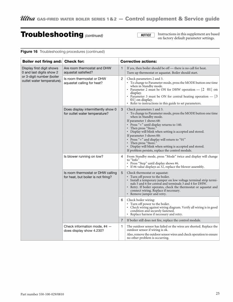
Boiler not firing and: Check for: Corrective actions:
Display first digit shows 0 and last digits show 2 or 3-digit number (boiler outlet water temperature).
Are room thermostat and DHW aquastat satisfied?
1 If yes, then boiler should be off — there is no call for heat. Turn up thermostat or aquastat. Boiler should start.
Is room thermostat or DHW aquastat calling for heat?
2 Check parameters 2 and 3.To change to Parameter mode, press the MODE button one time when in Standby mode.Parameter 2 must be ON for DHW operation — [2 01] on display.Parameter 3 must be ON for central heating operation — [3 01] on display.Refer to instructions in this guide to set parameters.
Does display intermittently show 0 for outlet water temperature?
3 Check parameters 1 and 3.To change to Parameter mode, press the MODE button one time when in Standby mode.
If parameter 1 shows 68:Press “+” until display returns to 140.Then press “Store.”Display will blink when setting is accepted and stored.
If parameter 3 shows 00:Press “+” and display will return to “01”Then press “Store.”Display will blink when setting is accepted and stored.
If problem persists, replace the control module.
Is blower running on low? 4 From Standby mode, press “Mode” twice and display will change to “Info”
Press “Step” until display shows #6.If #6 value displays as 32, replace the blower assembly.
Is room thermostat or DHW calling for heat, but boiler is not firing?
5 Check thermostat or aquastat:Turn off power to the boiler.Install a temporary jumper on low voltage terminal strip termi-nals 5 and 6 for central and terminals 3 and 4 for DHW.Retry. If boiler operates, check the thermostat or aquastat and connect wiring. Replace if necessary.Remove jumper and retry.
6 Check boiler wiring:Turn off power to the boiler.Check wiring against wiring diagram. Verify all wiring is in good condition and securely fastened.Replace harness if necessary and retry.
7 If boiler still does not fire, replace the control module.
Check information mode, #4 — does display show 4.230?
1 The outdoor sensor has failed or the wires are shorted. Replace the outdoor sensor if wiring is ok.Also, remove the outdoor sensor wires and check operation to ensure no other problem is occurring.
Troubleshooting procedures (continued)
Troubleshooting (continued) Instructions in this supplement are based on factory default parameter settings.
26 Part number 550-100-029/0810
GAS-FIRED WATER BOILER SERIES 1 & 2 — Control supplement & Service guide
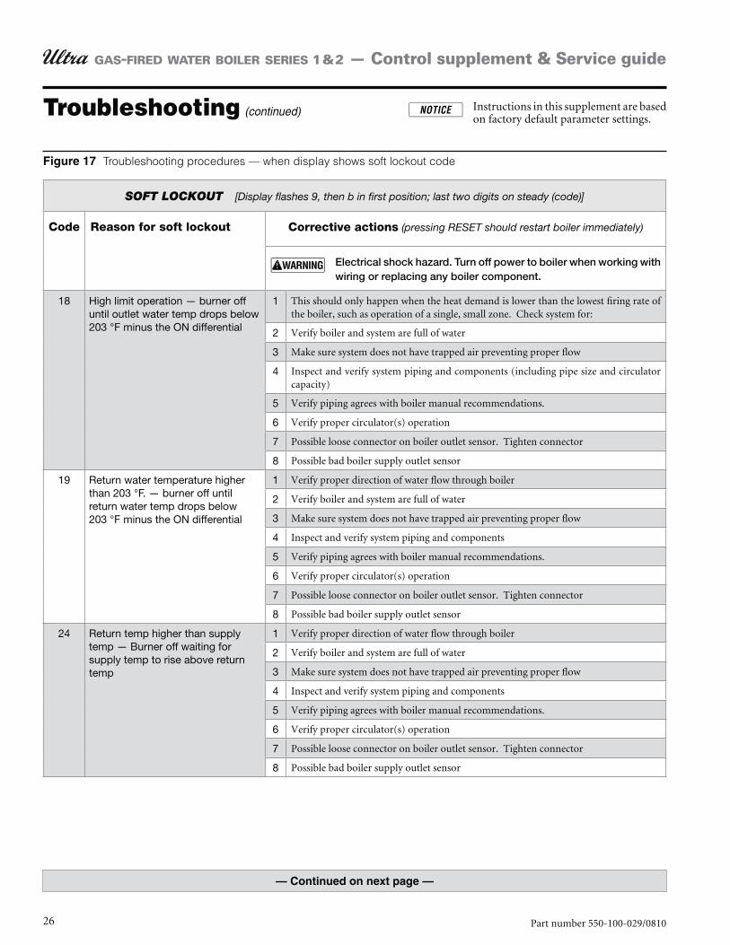
Troubleshooting (continued) Instructions in this supplement are based on factory default parameter settings.
SOFT LOCKOUT [Display flashes 9, then b in first position; last two digits on steady (code)]
Code Reason for soft lockout Corrective actions (pressing RESET should restart boiler immediately)
Electrical shock hazard. Turn off power to boiler when working with wiring or replacing any boiler component.
18 High limit operation — burner off until outlet water temp drops below 203 °F minus the ON differential
1 This should only happen when the heat demand is lower than the lowest firing rate of the boiler, such as operation of a single, small zone. Check system for:
2 Verify boiler and system are full of water
3 Make sure system does not have trapped air preventing proper flow
4 Inspect and verify system piping and components (including pipe size and circulator capacity)
5 Verify piping agrees with boiler manual recommendations.
6 Verify proper circulator(s) operation
7 Possible loose connector on boiler outlet sensor. Tighten connector
8 Possible bad boiler supply outlet sensor
19 Return water temperature higher than 203 °F. — burner off until return water temp drops below 203 °F minus the ON differential
1 Verify proper direction of water flow through boiler
2 Verify boiler and system are full of water
3 Make sure system does not have trapped air preventing proper flow
4 Inspect and verify system piping and components
5 Verify piping agrees with boiler manual recommendations.
6 Verify proper circulator(s) operation
7 Possible loose connector on boiler outlet sensor. Tighten connector
8 Possible bad boiler supply outlet sensor
24 Return temp higher than supply temp — Burner off waiting for supply temp to rise above return temp
1 Verify proper direction of water flow through boiler
2 Verify boiler and system are full of water
3 Make sure system does not have trapped air preventing proper flow
4 Inspect and verify system piping and components
5 Verify piping agrees with boiler manual recommendations.
6 Verify proper circulator(s) operation
7 Possible loose connector on boiler outlet sensor. Tighten connector
8 Possible bad boiler supply outlet sensor
Troubleshooting procedures — when display shows soft lockout code
27Part number 550-100-029/0810
GAS-FIRED WATER BOILER SERIES 1 & 2 — Control supplement & Service guide
Troubleshooting (continued) Instructions in this supplement are based on factory default parameter settings.
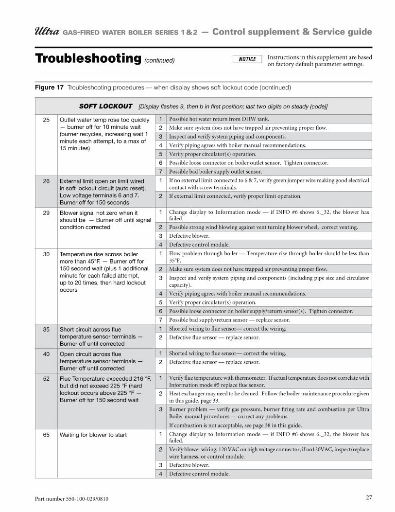
SOFT LOCKOUT [Display flashes 9, then b in first position; last two digits on steady (code)]
25 Outlet water temp rose too quickly — burner off for 10 minute wait (burner recycles, increasing wait 1 minute each attempt, to a max of 15 minutes)
1 Possible hot water return from DHW tank.
2 Make sure system does not have trapped air preventing proper flow.
3 Inspect and verify system piping and components.
4 Verify piping agrees with boiler manual recommendations.
5 Verify proper circulator(s) operation.
6 Possible loose connector on boiler outlet sensor. Tighten connector.
7 Possible bad boiler supply outlet sensor.
26 External limit open on limit wired in soft lockout circuit (auto reset). Low voltage terminals 6 and 7. Burner off for 150 seconds
1 If no external limit connected to 6 & 7, verify green jumper wire making good electrical contact with screw terminals.
2 If external limit connected, verify proper limit operation.
29 Blower signal not zero when it should be — Burner off until signal condition corrected
1 Change display to Information mode — if INFO #6 shows 6._32, the blower has failed.
2 Possible strong wind blowing against vent turning blower wheel, correct venting.
3 Defective blower.
4 Defective control module.
30 Temperature rise across boiler more than 45°F. — Burner off for 150 second wait (plus 1 additional minute for each failed attempt, up to 20 times, then hard lockout occurs
1 Flow problem through boiler — Temperature rise through boiler should be less than 35°F.
2 Make sure system does not have trapped air preventing proper flow.
3 Inspect and verify system piping and components (including pipe size and circulator capacity).
4 Verify piping agrees with boiler manual recommendations.
5 Verify proper circulator(s) operation.
6 Possible loose connector on boiler supply/return sensor(s). Tighten connector.
7 Possible bad supply/return sensor — replace sensor.
35 Short circuit across flue temperature sensor terminals — Burner off until corrected
1 Shorted wiring to flue sensor— correct the wiring.
2 Defective flue sensor — replace sensor.
40 Open circuit across flue temperature sensor terminals — Burner off until corrected
1 Shorted wiring to flue sensor— correct the wiring.
2 Defective flue sensor — replace sensor.
52 Flue Temperature exceeded 216 °F. but did not exceed 225 °F (hard lockout occurs above 225 °F — Burner off for 150 second wait
1 Verify flue temperature with thermometer. If actual temperature does not correlate with Information mode #5 replace flue sensor.
2 Heat exchanger may need to be cleaned. Follow the boiler maintenance procedure given in this guide, page 33.
3 Burner problem — verify gas pressure, burner firing rate and combustion per Ultra Boiler manual procedures — correct any problems.
If combustion is not acceptable, see page 38 in this guide.
65 Waiting for blower to start 1 Change display to Information mode — if INFO #6 shows 6._32, the blower has failed.
2 Verify blower wiring, 120 VAC on high voltage connector, if no120VAC, inspect/replace wire harness, or control module.
3 Defective blower.
4 Defective control module.
Troubleshooting procedures — when display shows soft lockout code (continued)
28 Part number 550-100-029/0810
GAS-FIRED WATER BOILER SERIES 1 & 2 — Control supplement & Service guide
Troubleshooting (continued) Instructions in this supplement are based on factory default parameter settings.
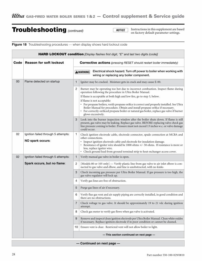
HARD LOCKOUT condition [Display flashes first digit, “E” and last two digits (code)]
Code Reason for soft lockout Corrective actions (pressing RESET should restart boiler immediately)
Electrical shock hazard. Turn off power to boiler when working with wiring or replacing any boiler component.
00 Flame detected on startup 1 Igniter may be cracked. Moisture gets in crack and may cause E-00.
2 Burner may be operating too hot due to incorrect combustion. Inspect flame during operation following the procedure in Ultra Boiler Manual.
If flame is acceptable at both high and low fire, go to step 3, below.
If flame is not acceptable:For propane boilers, verify propane orifice is correct and properly installed. See Ultra Boiler Manual for procedure. Obtain and install propane orifice if necessary.For correctly-orificed propane boiler or natural gas boiler, replace gas valve if burner glows excessively.
3 Look into the burner inspection window after the boiler shuts down. If flame is still present, gas valve may be leaking. Replace gas valve. BEFORE replacing valve check gas line pressure coming to boiler. Pressure must not exceed 13 inches w.c. or valve damage could occur.
02 Ignition failed through 5 attempts:
:
1 Check ignition electrode cable, electrode connector, spade connection at MCBA and other connections.
Inspect ignition electrode cable and electrode for insulation damage.Resistance of igniter wire should be 1000 ohms +/- 50 ohms. If resistance is more or less, replace igniter wire.Check ground lead from ground terminal strip to heat exchanger access cover.
02 Ignition failed through 5 attempts:
:
1 Verify manual gas valve in boiler is open.
2 [Models 80 or 105 only] — Verify plastic line from gas valve to air inlet elbow is con-nected to gas valve and elbow, and line is unobstructed, with no kinks
3 Check incoming gas pressure per Ultra Boiler Manual. If gas pressure is too high, the gas valve regulator will lock up.
4 Verify gas lines are free of obstruction.
5 Purge gas lines of air if necessary.
6 Verify flue gas vent and air supply piping are correctly installed, in good condition and there are no obstructions.
7 Check voltage to gas valve. It should be approximately 19 to 21 vdc during ignition attempt.
8 Check gas meter to verify gas flows when gas valve is activated.
9 Remove and inspect/clean ignition electrode per Ultra Boiler Manual. Clean white oxides if necessary. Replace ignition electrode if in poor condition or cannot be cleaned.
10 Ensure vent is clear. Restricted vent will not allow boiler to light.
Troubleshooting procedures — when display shows hard lockout code
29Part number 550-100-029/0810
GAS-FIRED WATER BOILER SERIES 1 & 2 — Control supplement & Service guide
Troubleshooting (continued) Instructions in this supplement are based on factory default parameter settings.
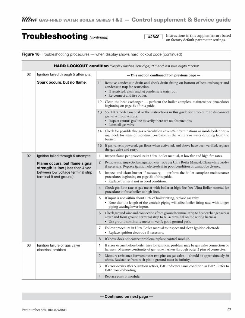
HARD LOCKOUT condition [Display flashes first digit, “E” and last two digits (code)]
02 Ignition failed through 5 attempts:
: 11 Remove condensate drain and check drain fitting on bottom of heat exchanger and condensate trap for restriction.
If restricted, clean and let condensate water out. Re-connect and fire boiler.
12 Clean the heat exchanger — perform the boiler complete maintenance procedures beginning on page 33 of this guide.
13 See Ultra Boiler manual or the instructions in this guide for procedure to disconnect gas valve from venturi.
Inspect venturi gas line to verify there are no obstructions. Reinstall gas valve.
14 Check for possible flue gas recirculation at vent/air terminations or inside boiler hous-ing. Look for signs of moisture, corrosion in the venturi or water dripping from the burner.
15 If gas valve is powered, gas flows when activated, and above have been verified, replace the gas valve and retry.
02 Ignition failed through 5 attempts:
( less than 4 vdc between low voltage terminal strip terminal 9 and ground):
1 Inspect flame per procedure in Ultra Boiler manual, at low fire and high fire rates.
2 Remove and inspect/clean ignition electrode per Ultra Boiler Manual. Clean white oxides if necessary. Replace ignition electrode if in poor condition or cannot be cleaned.
3 Inspect and clean burner if necessary — perform the boiler complete maintenance procedures beginning on page 33 of this guide.
Replace burner if not in good condition.
4 Check gas flow rate at gas meter with boiler at high fire (see Ultra Boiler manual for procedure to force boiler to high fire).
5 If input is not within about 10% of boiler rating, replace gas valve. Note that the length of the vent/air piping will affect boiler firing rate, with longer piping causing lower inputs.
6 Check ground wire and connections from ground terminal strip to heat exchanger access cover and from ground terminal strip to X1-6 terminal on the wiring harness.
Use ground continuity meter to verify good ground path.
7 Follow procedure in Ultra Boiler manual to inspect and clean ignition electrode. Replace ignition electrode if necessary.
8 If above does not correct problem, replace control module.
03 Ignition failure or gas valve electrical problem
1 If error occurs before boiler tries for ignition, problem may be gas valve connection or harness. Measure continuity of gas valve harness through outer 2 pins of connector.
2 Measure resistance between outer two pins on gas valve — should be approximately 50 ohms. Resistance from each pin to ground must be infinity.
3 If error occurs after 5 ignition retries, E-03 indicates same condition as E-02. Refer to E-02 troubleshooting.
4 Replace control module.
Troubleshooting procedures — when display shows hard lockout code (continued)
30 Part number 550-100-029/0810
GAS-FIRED WATER BOILER SERIES 1 & 2 — Control supplement & Service guide
Troubleshooting (continued) Instructions in this supplement are based on factory default parameter settings.
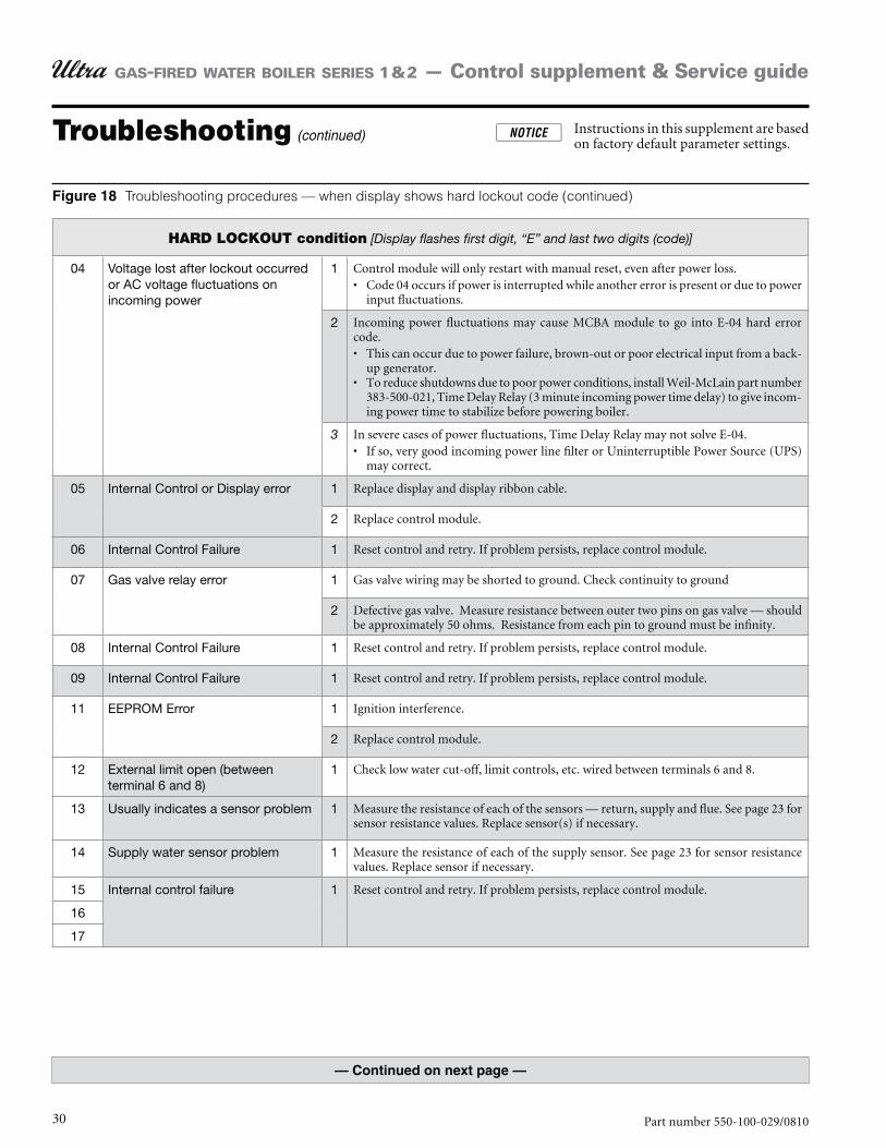
HARD LOCKOUT condition [Display flashes first digit, “E” and last two digits (code)]
04 Voltage lost after lockout occurred or AC voltage fluctuations on incoming power
1 Control module will only restart with manual reset, even after power loss. Code 04 occurs if power is interrupted while another error is present or due to power input fluctuations.
2 Incoming power fluctuations may cause MCBA module to go into E-04 hard error code.
This can occur due to power failure, brown-out or poor electrical input from a back-up generator.To reduce shutdowns due to poor power conditions, install Weil-McLain part number 383-500-021, Time Delay Relay (3 minute incoming power time delay) to give incom-ing power time to stabilize before powering boiler.
3 In severe cases of power fluctuations, Time Delay Relay may not solve E-04. If so, very good incoming power line filter or Uninterruptible Power Source (UPS) may correct.
05 Internal Control or Display error 1 Replace display and display ribbon cable.
2 Replace control module.
06 Internal Control Failure 1 Reset control and retry. If problem persists, replace control module.
07 Gas valve relay error 1 Gas valve wiring may be shorted to ground. Check continuity to ground
2 Defective gas valve. Measure resistance between outer two pins on gas valve — should be approximately 50 ohms. Resistance from each pin to ground must be infinity.
08 Internal Control Failure 1 Reset control and retry. If problem persists, replace control module.
09 Internal Control Failure 1 Reset control and retry. If problem persists, replace control module.
11 EEPROM Error 1 Ignition interference.
2 Replace control module.
12 External limit open (between terminal 6 and 8)
1 Check low water cut-off, limit controls, etc. wired between terminals 6 and 8.
13 Usually indicates a sensor problem 1 Measure the resistance of each of the sensors — return, supply and flue. See page 23 for sensor resistance values. Replace sensor(s) if necessary.
14 Supply water sensor problem 1 Measure the resistance of each of the supply sensor. See page 23 for sensor resistance values. Replace sensor if necessary.
15 Internal control failure 1 Reset control and retry. If problem persists, replace control module.
16
17
Troubleshooting procedures — when display shows hard lockout code (continued)
31Part number 550-100-029/0810
GAS-FIRED WATER BOILER SERIES 1 & 2 — Control supplement & Service guide
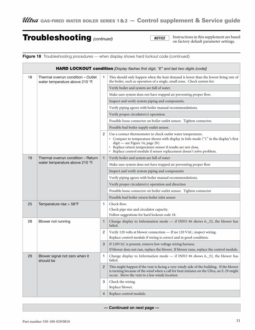
HARD LOCKOUT condition [Display flashes first digit, “E” and last two digits (code)]
18 Thermal overrun condition – Outlet water temperature above 210 °F.
1 This should only happen when the heat demand is lower than the lowest firing rate of the boiler, such as operation of a single, small zone. Check system for:
Verify boiler and system are full of water.
Make sure system does not have trapped air preventing proper flow.
Inspect and verify system piping and components.
Verify piping agrees with boiler manual recommendations.
Verify proper circulator(s) operation.
Possible loose connector on boiler outlet sensor. Tighten connector.
Possible bad boiler supply outlet sensor.
2 Use a contact thermometer to check outlet water temperature. Compare to temperature shown with display in Info mode (“1” in the display’s first digit — see Figure 14, page 20). Replace return temperature sensor if results are not close. Replace control module if sensor replacement doesn’t solve problem.
19 Thermal overrun condition – Return water temperature above 210 °F.
1 Verify boiler and system are full of water
Make sure system does not have trapped air preventing proper flow
Inspect and verify system piping and components
Verify piping agrees with boiler manual recommendations.
Verify proper circulator(s) operation and direction
Possible loose connector on boiler outlet sensor. Tighten connector
Possible bad boiler return boiler inlet sensor
25 Temperature rise > 58°F 1 Check flow.
Check pipe size and circulator capacity.
Follow suggestions for hard lockout code 18.
28 Blower not running 1 Change display to Information mode — if INFO #6 shows 6._32, the blower has failed.
2 Verify 120 volts at blower connection — If no 120 VAC, inspect wiring.
Replace control module if wiring is correct and in good condition.
3 If 120VAC is present, remove low voltage wiring harness.
If blower does not run, replace the blower. If blower runs, replace the control module.
29 Blower signal not zero when it should be
1 Change display to Information mode — if INFO #6 shows 6._32, the blower has failed.
2 This might happen if the vent is facing a very windy side of the building. If the blower is turning because of the wind when a call for heat initiates on the Ultra, an E-29 might occur. Move the vent to a less windy location
3 Check the wiring.
Replace blower.
4 Replace control module.
Troubleshooting procedures — when display shows hard lockout code (continued)
Troubleshooting (continued) Instructions in this supplement are based on factory default parameter settings.

32 Part number 550-100-029/0810
GAS-FIRED WATER BOILER SERIES 1 & 2 — Control supplement & Service guide
HARD LOCKOUT condition [Display flashes first digit, “E” and last two digits (code)]
30 Temperature rise across boiler over 58 °F, and occurred 20 times.
1 Flow problem through boiler — Temperature rise through boiler should be less than 35 °F.
2 Make sure system does not have trapped air preventing proper flow.
3 Inspect and verify system piping and components.
4 Verify piping agrees with boiler manual recommendations.
5 Verify proper circulator(s) operation.
6 Possible loose connector on boiler supply/return sensor(s). Tighten connector.
7 Possible bad supply/return sensor.
31 Outlet water temperature sensor short circuit.
1 Inspect outlet water temperature sensor and wiring. Replace sensor if wiring correct and in good condition. Replace low voltage wiring harness if problem persists. Replace control module if harness replacement doesn’t resolve.
32 Return water temperature sensor short circuit.
1 Inspect return water temperature sensor and wiring. Replace sensor if wiring correct and in good condition. Replace low voltage wiring harness if problem persists. Replace control module if harness replacement doesn’t resolve.
36 Outlet water temperature sensor open circuit.
1 Inspect outlet water temperature sensor and wiring. Replace sensor if wiring correct and in good condition. Replace low voltage wiring harness if problem persists. Replace control module if harness replacement doesn’t resolve.
37 Return water temperature sensor open circuit.
1 Inspect return water temperature sensor and wiring. Replace sensor if wiring correct and in good condition. Replace low voltage wiring harness if problem persists. Replace control module if harness replacement doesn’t resolve.
44 Internal control failure 1 Reset control and retry. If problem persists, replace control module.
52 Flue temperature exceeded 225 °F. 1 Verify flue temperature with thermometer. If actual temperature does not correlate with Information mode #5, replace flue sensor
2 Heat exchanger may need to be cleaned — perform the boiler complete maintenance procedures beginning on page 33 of this guide.
3 Burner problem — verify gas pressure, burner firing rate, combustion. Correct prob-lems.
If combustion is still unacceptable, follow the procedures beginning on page 38 of this guide.
60 Internal control failure 1 Reset control and retry. If problem persists, replace control module.
61 Internal control failure 1 Reset control and retry. If problem persists, replace control module.
65 Blower signal too low (not enough driving force)
1 Inspect wiring and connections. If wiring is correct, replace blower assembly. If blower assembly replacement is unsuccessful, replace control module.
Troubleshooting procedures — when display shows hard lockout code (continued)
Troubleshooting (continued) Instructions in this supplement are based on factory default parameter settings.
33Part number 550-100-029/0810
GAS-FIRED WATER BOILER SERIES 1 & 2 — Control supplement & Service guide
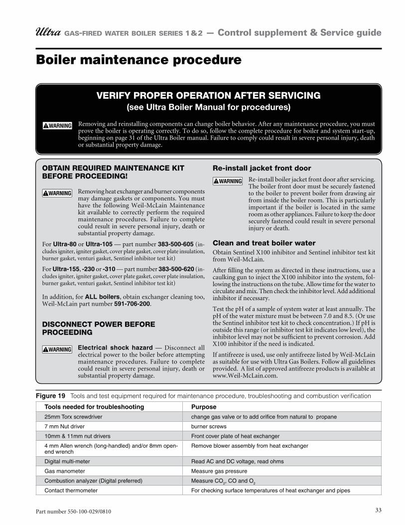
Boiler maintenance procedure
VERIFY PROPER OPERATION AFTER SERVICING (see Ultra Boiler Manual for procedures)
Removing and reinstalling components can change boiler behavior. After any maintenance procedure, you must prove the boiler is operating correctly. To do so, follow the complete procedure for boiler and system start-up, beginning on page 31 of the Ultra Boiler manual. Failure to comply could result in severe personal injury, death or substantial property damage.
OBTAIN REQUIRED MAINTENANCE KIT BEFORE PROCEEDING!
Removing heat exchanger and burner components may damage gaskets or components. You must have the following Weil-McLain Maintenance kit available to correctly perform the required maintenance procedures. Failure to complete could result in severe personal injury, death or substantial property damage.
For or — part number 383-500-605 (in-cludes igniter, igniter gasket, cover plate gasket, cover plate insulation, burner gasket, venturi gasket, Sentinel inhibitor test kit)
For , -230 or -310 — part number 383-500-620 (in-cludes igniter, igniter gasket, cover plate gasket, cover plate insulation, burner gasket, venturi gasket, Sentinel inhibitor test kit)
In addition, for , obtain exchanger cleaning too, Weil-McLain part number .
DISCONNECT POWER BEFORE PROCEEDING
— Disconnect all electrical power to the boiler before attempting maintenance procedures. Failure to complete could result in severe personal injury, death or substantial property damage.
Re-install jacket front door
Re-install boiler jacket front door after servicing. The boiler front door must be securely fastened to the boiler to prevent boiler from drawing air from inside the boiler room. This is particularly important if the boiler is located in the same room as other appliances. Failure to keep the door securely fastened could result in severe personal injury or death.
Clean and treat boiler waterObtain Sentinel X100 inhibitor and Sentinel inhibitor test kit from Weil-McLain.
After filling the system as directed in these instructions, use a caulking gun to inject the X100 inhibitor into the system, fol-lowing the instructions on the tube. Allow time for the water to circulate and mix. Then check the inhibitor level. Add additional inhibitor if necessary.
Test the pH of a sample of system water at least annually. The pH of the water mixture must be between 7.0 and 8.5. (Or use the Sentinel inhibitor test kit to check concentration.) If pH is outside this range (or inhibitor test kit indicates low level), the inhibitor level may not be sufficient to prevent corrosion. Add X100 inhibitor if the need is indicated.
If antifreeze is used, use only antifreeze listed by Weil-McLain as suitable for use with Ultra Gas Boilers. Follow all guidelines provided. A list of approved antifreeze products is available at www.Weil-McLain.com.
Tools and test equipment required for maintenance procedure, troubleshooting and combustion verification
25mm Torx screwdriver change gas valve or to add orifice from natural to propane
7 mm Nut driver burner screws
10mm & 11mm nut drivers Front cover plate of heat exchanger
4 mm Allen wrench (long-handled) and/or 8mm open-end wrench
Remove blower assembly from heat exchanger
Digital multi-meter Read AC and DC voltage, read ohms
Gas manometer Measure gas pressure
Combustion analyzer (Digital preferred) Measure CO2, CO and O2
Contact thermometer For checking surface temperatures of heat exchanger and pipes
34 Part number 550-100-029/0810
GAS-FIRED WATER BOILER SERIES 1 & 2 — Control supplement & Service guide
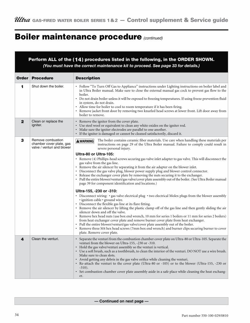
Boiler maintenance procedure (continued)
Perform ALL of the ( 14 ) procedures listed in the following, in the ORDER SHOWN. (You must have the correct maintenance kit to proceed. See page 33 for details.)
Order Procedure Description
1 Shut down the boiler. Follow “To Turn Off Gas to Appliance” instructions under Lighting instructions on boiler label and in Ultra Boiler manual. Make sure to close the external manual gas cock to prevent gas flow to the boiler.Do not drain boiler unless it will be exposed to freezing temperatures. If using freeze prevention fluid in system, do not drain.Allow time for boiler to cool to room temperature if it has been firing.Remove jacket front door by removing two knurled head screws at lower front. Lift door away from boiler to remove.
2 Clean or replace the igniter.
Remove the igniter from the cover plate.Use steel wool or equivalent to clean any white oxides on the igniter rod.Make sure the igniter electrodes are parallel to one another.If the igniter is damaged or cannot be cleaned satisfactorily, discard it.
3 Remove combustion chamber cover plate, gas valve / venturi and blower
The boiler contains ceramic fiber materials. Use care when handling these materials per instructions on page 29 of the Ultra Boiler manual. Failure to comply could result in severe personal injury.
Remove (4) Phillips-head screws securing gas valve inlet adapter to gas valve. This will disconnect the gas valve from the gas line.Remove the air silencer by separating it from the air adapter on the blower inlet.Disconnect the gas valve plug, blower power supply plug and blower control connector.Release the exchanger cover plate by removing the nuts securing it to the exchanger.Pull the entire blower/venturi/gas valve/cover plate assembly out of the boiler. (See Ultra Boiler manual page 39 for component identification and locations.)
Disconnect the flexible gas line at its flare fitting.Remove the air silencer by lifting the plastic clamp off of the gas line and then gently sliding the air silencer down and off the valve.Remove hex head nuts (use box end wrench, 10 mm for series 1 boilers or 11 mm for series 2 boilers) from heat exchanger cover plate and remove burner cover plate from heat exchanger.Pull the entire blower/venturi/gas valve/cover plate assembly out of the boiler.Remove three M4 hex head screws (7mm box end wrench) and burner clips securing burner to cover plate. Remove cover plate.
4 Clean the venturi. Separate the venturi from the combustion chamber cover plate on Ultra-80 or Ultra-105. Separate the venturi from the blower on Ultra-155, -230 or -310.Hold the gas valve/venturi assembly so the venturi is vertical.Use a soft brush, such as a toothbrush, to clean the interior of the venturi. DO NOT use a wire brush. Make sure to clean slots.Avoid getting any debris in the gas valve orifice while cleaning the venturi.Re-attach the venturi to the cover plate (Ultra-80 or -105) or to the blower (Ultra-155, -230 or -310).Set combustion chamber cover plate assembly aside in a safe place while cleaning the heat exchang-er.
35Part number 550-100-029/0810
GAS-FIRED WATER BOILER SERIES 1 & 2 — Control supplement & Service guide
Perform ALL of the ( 14 ) procedures listed in the following, in the ORDER SHOWN. (You must have the correct maintenance kit to proceed. See page 33 for details.)
Order Procedure Description
5 Clean the burner. See Figure 20, page 37 for burner access and assembly.Remove the burner retaining hardware and remove burner from cover plate.Brush the exterior of the burner with a nylon-bristle brush (DO NOT use a wire brush).Use a vacuum cleaner or compressed air to clean the interior of the burner. When using compressed air, wear protective eye gear. Compressed air should only be used when cleaning the burner outdoors.
6 Replace combustion chamber cover plate insulation and gaskets.
Reassemble the burner to the cover plate (see Figure 20, page 37).Replace cover plate insulation and gaskets on cover plate.Set aside until the heat exchanger has been cleaned as described below.
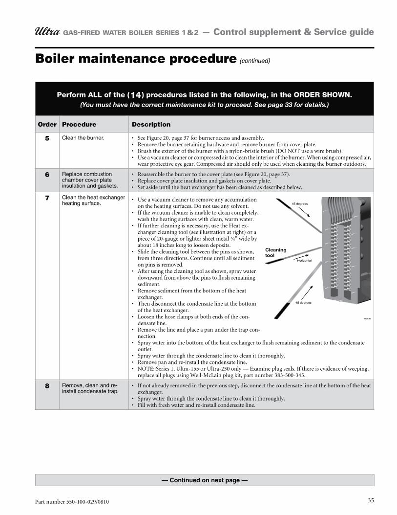
7 Clean the heat exchanger heating surface.
Use a vacuum cleaner to remove any accumulation on the heating surfaces. Do not use any solvent.If the vacuum cleaner is unable to clean completely, wash the heating surfaces with clean, warm water. If further cleaning is necessary, use the Heat ex-changer cleaning tool (see illustration at right) or a piece of 20-gauge or lighter sheet metal ¾” wide by about 18 inches long to loosen deposits. Slide the cleaning tool between the pins as shown, from three directions. Continue until all sediment on pins is removed.After using the cleaning tool as shown, spray water downward from above the pins to flush remaining sediment.Remove sediment from the bottom of the heat exchanger.Then disconnect the condensate line at the bottom of the heat exchanger.Loosen the hose clamps at both ends of the con-densate line.Remove the line and place a pan under the trap con-nection.Spray water into the bottom of the heat exchanger to flush remaining sediment to the condensate outlet.Spray water through the condensate line to clean it thoroughly.Remove pan and re-install the condensate line.NOTE: Series 1, Ultra-155 or Ultra-230 only — Examine plug seals. If there is evidence of weeping, replace all plugs using Weil-McLain plug kit, part number 383-500-345.
8 Remove, clean and re-install condensate trap.
If not already removed in the previous step, disconnect the condensate line at the bottom of the heat exchanger.Spray water through the condensate line to clean it thoroughly.Fill with fresh water and re-install condensate line.
Boiler maintenance procedure (continued)
36 Part number 550-100-029/0810
GAS-FIRED WATER BOILER SERIES 1 & 2 — Control supplement & Service guide
Boiler maintenance procedure (continued)
Perform ALL of the ( 14 ) procedures listed in the following, in the ORDER SHOWN. (You must have the correct maintenance kit to proceed. See page 33 for details.)
Order Procedure Description
9 Re-install the combustion chamber cover plate assembly and igniter.
You must have the maintenance kit specified on page 33.
Inspect the heat exchanger cover plate insulation. Replace if insulation is damaged. Read the ceramic fiber WARNING on page 93 of the Ultra Boiler manual before handling or disposing of ceramic fiber materials.
When re-installing the heat exchanger cover plate, you must gradually tighten the cover plate nuts. Follow the tightening sequence shown in Figure 21, page 37, making two or three passes with a torque wrench. The final torque MUST NOT exceed 50 inch-pounds, +/- 10 inch-pounds.
Reinstall the blower/venturi/gas valve/cover plate assembly. Follow the tightening sequence shown in Figure 21, page 37, making two or three passes with a torque wrench to install the nuts.
If the valve adapter block is removed, carefully inspect the O-ring that should still be in the gas valve inlet adapter block. The O-ring must be in good condition and must be installed when gas valve is reconnected. Failure to comply will cause a gas leak, resulting in severe personal injury or death.
Reconnect the flexible gas line.Reinstall the air silencer by pressing onto the air inlet adapter.Perform a soap suds leak test on all interior gas piping after starting the boiler.
Place cover plate gasket in groove of heat exchanger cover plate. Re-install cover plate.Follow the tightening sequence shown in Figure 21, page 37, making two or three passes with a torque wrench to install the nutsReinstall air silencer by sliding on gas valve venturi and securing clamp to gas line.
Perform a soap suds leak test on all interior gas piping after starting the boiler.
10 Re-install the igniter and check ignition ground wiring.
After the cover plate is re-installed on the heat exchanger, install the igniter.If the existing igniter was successfully cleaned, you can re-install it. If not, or to reduce the possibil-ity of problems, install the new igniter included in the Maintenance kit. Attach igniter, making sure the gasket is in good condition and correctly positioned.Reconnect green ground wire. Check ground wire, ignition wire and connections.
11 Check all boiler wiring. Inspect all boiler wiring, making sure all wires are in good condition and securely attached.
12 Check flue vent and air piping system.
Visually inspect entire flue gas venting system and air piping for blockage, deterioration or leakage. Re-pair any joint that shows signs of leakage in accordance with the vent manufacturers instructions. Where combustion air is ducted to boiler, verify that air inlet piping is connected and properly sealed.Verify that all combustion and ventilation air openings are to the boiler room and/or building are open and unobstructed. Check operation and wiring of automatic combustion air dampers, if used.Verify that boiler discharge and air intake is clean and free of obstructions.
13 Restart boiler and run combustion tests.
Follow the Ultra Boiler manual Start-up procedures.Start the boiler and perform combustion tests as specified in the Ultra Boiler manual.
14 If combustion results are unacceptable, follow the procedure beginning on page 38.
Ultra boilers do no typically require field adjustment of the gas valve. However, it may be necessary to verify and possibly adjust the combustion settings.When combustion results obtained using the Ultra Boiler manual procedures, see page 38 for procedure to adjust for proper combustion.
The adjustment specified in the procedure of page 38 must only be performed by a quali-fied service technician, using combustion test instruments. Failure to comply could result in severe personal injury, death or substantial property damage.
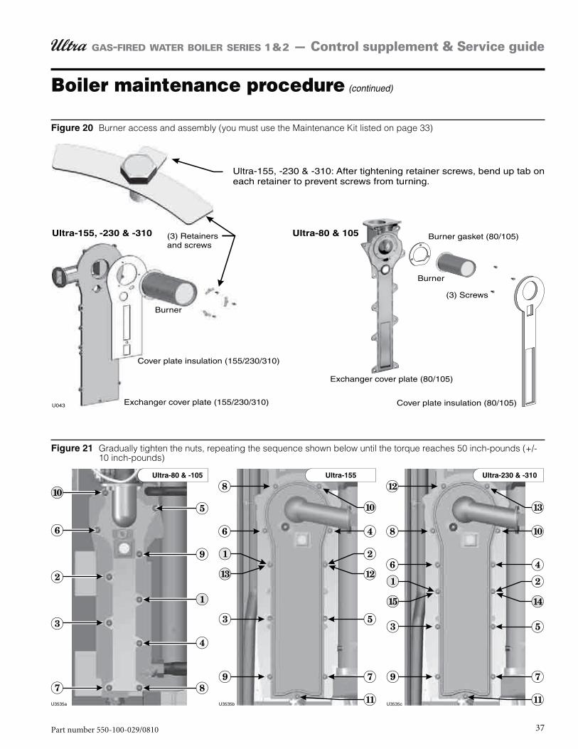
37Part number 550-100-029/0810
GAS-FIRED WATER BOILER SERIES 1 & 2 — Control supplement & Service guide
Burner access and assembly (you must use the Maintenance Kit listed on page 33)
Gradually tighten the nuts, repeating the sequence shown below until the torque reaches 50 inch-pounds (+/- 10 inch-pounds)
Boiler maintenance procedure (continued)
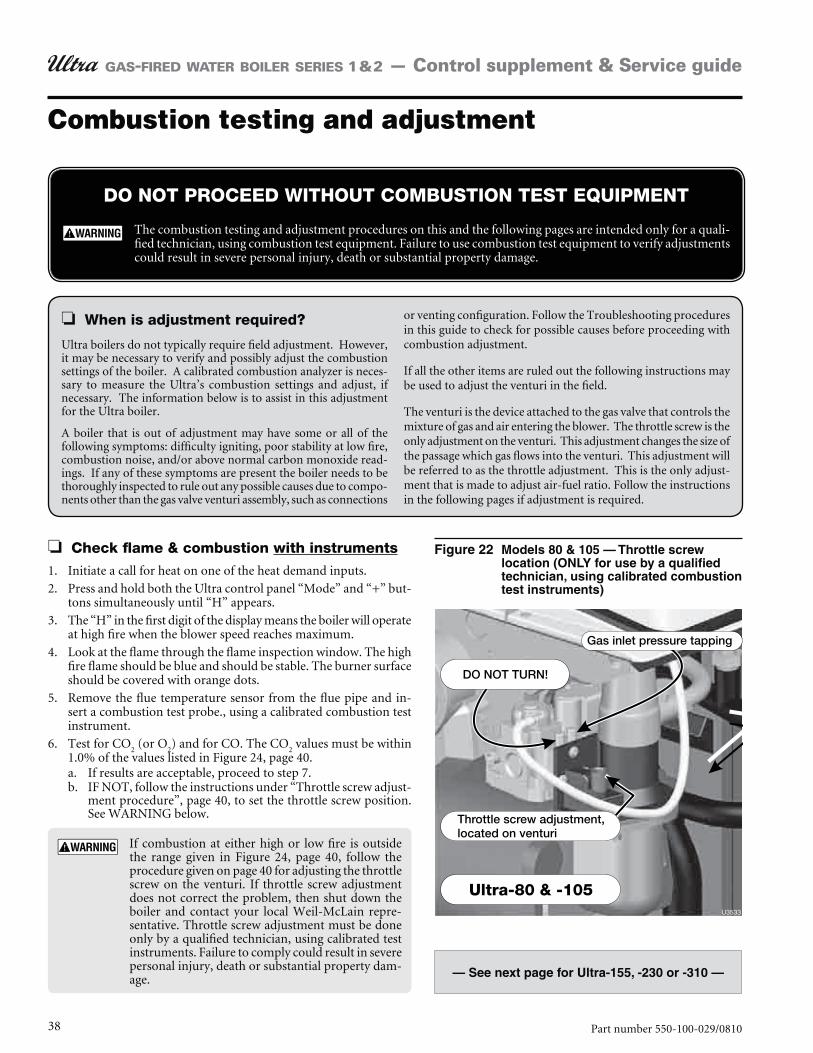
38 Part number 550-100-029/0810
GAS-FIRED WATER BOILER SERIES 1 & 2 — Control supplement & Service guide
Combustion testing and adjustment
Check flame & combustion with instruments
Initiate a call for heat on one of the heat demand inputs.1.
Press and hold both the Ultra control panel “Mode” and “+” but-2. tons simultaneously until “H” appears.
The “H” in the first digit of the display means the boiler will operate 3. at high fire when the blower speed reaches maximum.
Look at the flame through the flame inspection window. The high 4. fire flame should be blue and should be stable. The burner surface should be covered with orange dots.
Remove the flue temperature sensor from the flue pipe and in-5. sert a combustion test probe., using a calibrated combustion test instrument.
Test for CO6. 2 (or O
2) and for CO. The CO
2 values must be within
1.0% of the values listed in Figure 24, page 40.If results are acceptable, proceed to step a. 7. IF NOT, follow the instructions under b. “Throttle screw adjust-ment procedure”, page 40, to set the throttle screw position. See WARNING below.
If combustion at either high or low fire is outside the range given in Figure 24, page 40, follow the procedure given on page 40 for adjusting the throttle screw on the venturi. If throttle screw adjustment does not correct the problem, then shut down the boiler and contact your local Weil-McLain repre-sentative. Throttle screw adjustment must be done only by a qualified technician, using calibrated test instruments. Failure to comply could result in severe personal injury, death or substantial property dam-age.
DO NOT PROCEED WITHOUT COMBUSTION TEST EQUIPMENT
The combustion testing and adjustment procedures on this and the following pages are intended only for a quali-fied technician, using combustion test equipment. Failure to use combustion test equipment to verify adjustments could result in severe personal injury, death or substantial property damage.
When is adjustment required?
Ultra boilers do not typically require field adjustment. However, it may be necessary to verify and possibly adjust the combustion settings of the boiler. A calibrated combustion analyzer is neces-sary to measure the Ultra’s combustion settings and adjust, if necessary. The information below is to assist in this adjustment for the Ultra boiler.
A boiler that is out of adjustment may have some or all of the following symptoms: difficulty igniting, poor stability at low fire, combustion noise, and/or above normal carbon monoxide read-ings. If any of these symptoms are present the boiler needs to be thoroughly inspected to rule out any possible causes due to compo-nents other than the gas valve venturi assembly, such as connections
or venting configuration. Follow the Troubleshooting procedures in this guide to check for possible causes before proceeding with combustion adjustment.
If all the other items are ruled out the following instructions may be used to adjust the venturi in the field.
The venturi is the device attached to the gas valve that controls the mixture of gas and air entering the blower. The throttle screw is the only adjustment on the venturi. This adjustment changes the size of the passage which gas flows into the venturi. This adjustment will be referred to as the throttle adjustment. This is the only adjust-ment that is made to adjust air-fuel ratio. Follow the instructions in the following pages if adjustment is required.

39Part number 550-100-029/0810
GAS-FIRED WATER BOILER SERIES 1 & 2 — Control supplement & Service guide
Combustion testing and adjustment (continued)
Measure natural gas input:7. Operate boiler 10 minutes.a. Turn off other appliances.b. At natural gas meter, measure time (in seconds) required to c. use one cubic foot of gas.Calculate gas input:d.
3600 x 1000number of seconds from step c
= Btuh
Btuh calculated should approximate input rating on boiler e. rating label.
Press and hold the Ultra control panel “Mode” and “-” buttons 8. simultaneously until the display shows “L”.
The “L” in the first digit means the boiler will operate at low fire 9. when the blower speed reaches minimum.
Look at the flame through the flame inspection window. The low 10. fire flame should be stable and evenly distributed over burner surface with a uniform orange color.
Test for CO11. 2 (or O
2) and for CO. The CO
2 values must be within
1.0% of the values listed in Figure 24, page 40.If results are acceptable, proceed to step .a. IF NOT, follow the instructions under b. “Throttle screw adjust-ment procedure”, page 40, to set the throttle screw position. See WARNING below.
If combustion at either high or low fire is outside the range given in Figure 24, page 40, follow the procedure given on page 40 for adjusting the throttle screw on the venturi. If throttle screw adjustment does not correct the problem, then shut down the boiler and contact your local Weil-McLain repre-sentative. Throttle screw adjustment must be done only by a qualified technician, using calibrated test instruments. Failure to comply could result in severe personal injury, death or substantial property dam-age.
If combustion test results at high fire and low fire are correct, press 12. and hold the “+” and “-” buttons to return boiler to automatic firing.
Re-install the flue gas temperature sensor. When inserting the 13. sensor, remove the rubber grommet from the probe. Insert the rubber grommet into the flue pipe, then insert the probe into the rubber grommet.
You must re-install the flue gas temperature sensor to prevent flue gas spillage into the boiler enclosure. Failure to comply could result in severe personal injury, death or substantial property damage.
Re-install boiler jacket front door after servicing. The boiler front door must be securely fastened to the boiler to prevent boiler from drawing air from inside the boiler room. This is particularly important if the boiler is lo-cated in the same room as other appliances. Failure to keep the door securely fastened could result in severe personal injury or death.
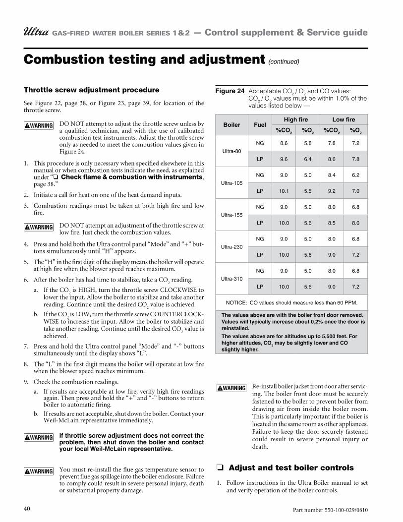
40 Part number 550-100-029/0810
GAS-FIRED WATER BOILER SERIES 1 & 2 — Control supplement & Service guide
Combustion testing and adjustment (continued)
Acceptable CO2 / O2 and CO values: CO2 / O2 values must be within 1.0% of the values listed below —
2 2 2 2
Ultra-80
NG 8.6 5.8 7.8 7.2
LP 9.6 6.4 8.6 7.8
Ultra-105
NG 9.0 5.0 8.4 6.2
LP 10.1 5.5 9.2 7.0
Ultra-155
NG 9.0 5.0 8.0 6.8
LP 10.0 5.6 8.5 8.0
Ultra-230
NG 9.0 5.0 8.0 6.8
LP 10.0 5.6 9.0 7.2
Ultra-310
NG 9.0 5.0 8.0 6.8
LP 10.0 5.6 9.0 7.2
NOTICE: CO values should measure less than 60 PPM.
2
Throttle screw adjustment procedure
See Figure 22, page 38, or Figure 23, page 39, for location of the throttle screw.
DO NOT attempt to adjust the throttle screw unless by a qualified technician, and with the use of calibrated combustion test instruments. Adjust the throttle screw only as needed to meet the combustion values given in Figure 24.
This procedure is only necessary when specified elsewhere in this 1. manual or when combustion tests indicate the need, as explained under “ Check flame & combustion with instruments, page 38.”
Initiate a call for heat on one of the heat demand inputs.2.
Combustion readings must be taken at both high fire and low 3. fire.
DO NOT attempt an adjustment of the throttle screw at low fire. Just check the combustion values.
Press and hold both the Ultra control panel “Mode” and “+” but-4. tons simultaneously until “H” appears.
The “H” in the first digit of the display means the boiler will operate 5. at high fire when the blower speed reaches maximum.
After the boiler has had time to stabilize, take a CO6. 2 reading.
If the COa. 2 is HIGH, turn the throttle screw CLOCKWISE to
lower the input. Allow the boiler to stabilize and take another reading. Continue until the desired CO
2 value is achieved.
If the COb. 2 is LOW, turn the throttle screw COUNTERCLOCK-
WISE to increase the input. Allow the boiler to stabilize and take another reading. Continue until the desired CO
2 value is
achieved.
Press and hold the Ultra control panel “Mode” and “-” buttons 7. simultaneously until the display shows “L”.
The “L” in the first digit means the boiler will operate at low fire 8. when the blower speed reaches minimum.
Check the combustion readings.9.
If results are acceptable at low fire, verify high fire readings a. again. Then press and hold the “+” and “-” buttons to return boiler to automatic firing.
If results are not acceptable, shut down the boiler. Contact your b. Weil-McLain representative immediately.
You must re-install the flue gas temperature sensor to prevent flue gas spillage into the boiler enclosure. Failure to comply could result in severe personal injury, death or substantial property damage.
Re-install boiler jacket front door after servic-ing. The boiler front door must be securely fastened to the boiler to prevent boiler from drawing air from inside the boiler room. This is particularly important if the boiler is located in the same room as other appliances. Failure to keep the door securely fastened could result in severe personal injury or death.
Adjust and test boiler controls
Follow instructions in the Ultra Boiler manual to set 1. and verify operation of the boiler controls.
41Part number 550-100-029/0810
GAS-FIRED WATER BOILER SERIES 1 & 2 — Control supplement & Service guide
Ultra Control Module parameters
See information beginning on page 44 for detailed informa-tion on all Ultra control module parameters.
Parameter descriptions1. This section includes explanations of the adjustable parameters (begin-
ning on page 44).
Revise module parameters ONLY if you fully understand the purpose and result of the changes. Tampering with control settings can result in unreliable operation, with possible severe personal injury, death or substantial property damage.
2. You will find additional information on parameters and control opera-tion in the Ultra Control Supplement.
Default parameter settings1. Figure 26, page 43 lists the factory default settings for all Ultra models,
for standard altitudes (up to 5,500 feet) and high altitude (over 5,500 feet).
2. When in doubt, always restore parameters to the default settings listed in Figure 26, page 43.
When to change parameters1. Factory default settings will work for most applications. There are situ-
ations for which changes are desirable or even mandatory:
2. Default boiler settings are satisfactory for most high-mass systems (radiant slab, cast iron radiators, most finned-tube radiation).
Typical parameter changes
Outdoor reset applications1. Outdoor reset operation can sometimes be improved by adjusting
parameters 4, 5, 6 and 7. Parameters 9, 10 and 11 might also be modi-fied.
2. See page 44 for discussion of outdoor reset.
High altitude installations1. Minimum fan speed (parameter 17) and ignition fan speed (param-
eter 9) MUST be changed for operation at altitudes over 5,500 feet.
2. See the High Altitude Kit instructions for details. Change these param-eters following the High Altitude instructions. If revising the parameters, use ONLY the values given in Figure 26, page 43.
3. Also see page 47 for further discussion of fan speed parameters.
Overview of Ultra Control Module parameters
Fan-coil systems1. Systems using fan coil units respond to heat input
rapidly, and may require larger differential settings for best performance.
2. See page 49 for discussion of control differential and how to adjust.
High-mass systems1. High-mass systems, such as in-slab radiant and cast
iron radiator systems, respond slowly to heat input. The factory default settings will work well for most of these applications.
DO NOT Change the following:
Failure to comply with the following could cause equipment performance problems, resulting in potential severe personal injury, death or substantial property dam-age.
Parameter 2
Parameters 13 & 15
Parameters 17 & 19
Parameters 24, 25, 26 & 27
Parameter 32
Parameter 33-
tions.
Parameter 34 – first digit
Parameter 34 – second digit
AM-4. With AM-4, set second digit to 4 (0 - 10 V analog on AM-4: capacity).
Parameter 35 – both digits
Parameters 37, 39, 40 & 41
Parameter 42 – first digit
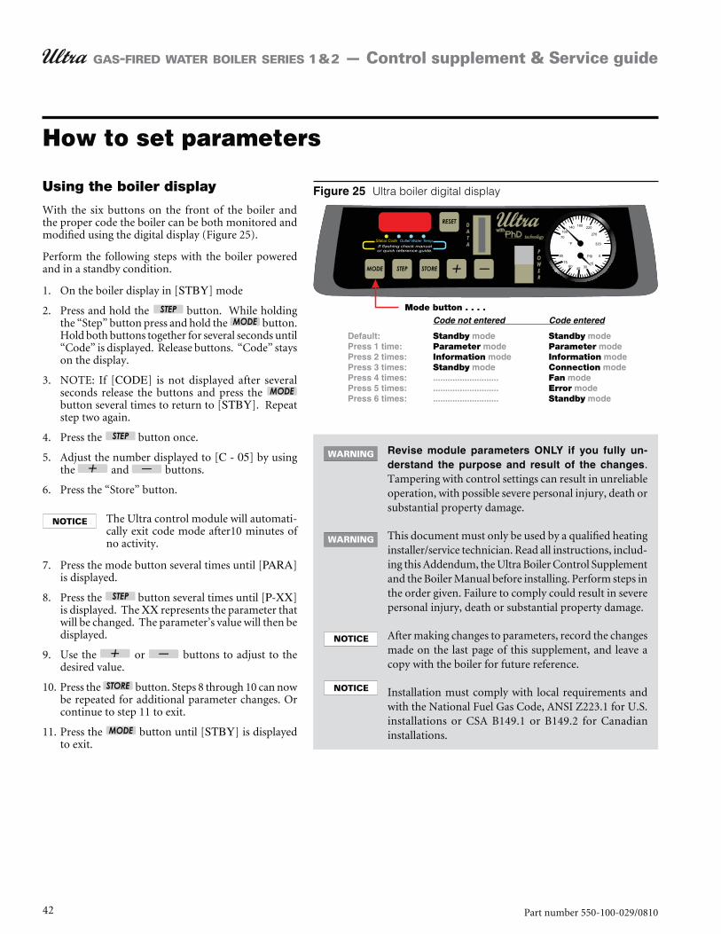
42 Part number 550-100-029/0810
GAS-FIRED WATER BOILER SERIES 1 & 2 — Control supplement & Service guide
How to set parameters
Using the boiler display
With the six buttons on the front of the boiler and the proper code the boiler can be both monitored and modified using the digital display (Figure 25).
Perform the following steps with the boiler powered and in a standby condition.
1. On the boiler display in [STBY] mode
2. Press and hold the button. While holding the “Step” button press and hold the button. Hold both buttons together for several seconds until “Code” is displayed. Release buttons. “Code” stays on the display.
3. NOTE: If [CODE] is not displayed after several seconds release the buttons and press the button several times to return to [STBY]. Repeat step two again.
4. Press the button once.
5. Adjust the number displayed to [C - 05] by using the and buttons.
6. Press the “Store” button.
The Ultra control module will automati-cally exit code mode after10 minutes of no activity.
7. Press the mode button several times until [PARA] is displayed.
8. Press the button several times until [P-XX] is displayed. The XX represents the parameter that will be changed. The parameter’s value will then be displayed.
9. Use the or buttons to adjust to the desired value.
10. Press the button. Steps 8 through 10 can now be repeated for additional parameter changes. Or continue to step 11 to exit.
11. Press the button until [STBY] is displayed to exit.
Ultra boiler digital display
-.
Tampering with control settings can result in unreliable operation, with possible severe personal injury, death or substantial property damage.
This document must only be used by a qualified heating installer/service technician. Read all instructions, includ-ing this Addendum, the Ultra Boiler Control Supplement and the Boiler Manual before installing. Perform steps in the order given. Failure to comply could result in severe personal injury, death or substantial property damage.
After making changes to parameters, record the changes made on the last page of this supplement, and leave a copy with the boiler for future reference.
Installation must comply with local requirements and with the National Fuel Gas Code, ANSI Z223.1 for U.S. installations or CSA B149.1 or B149.2 for Canadian installations.
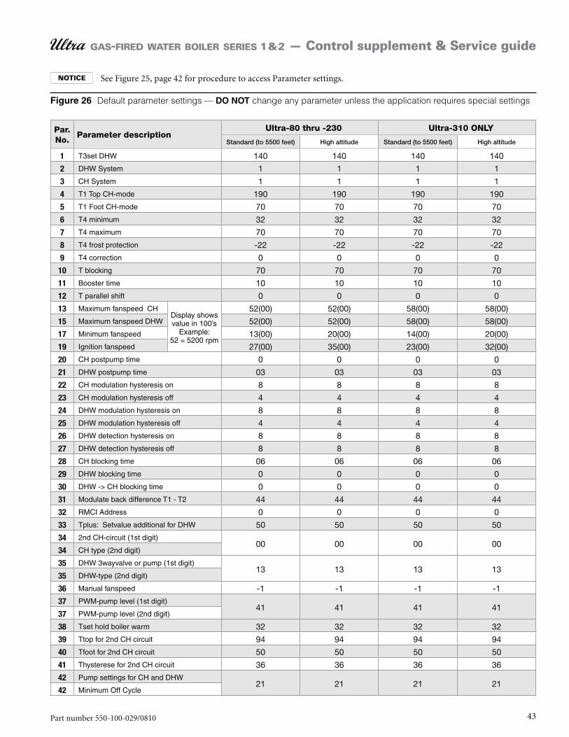
43Part number 550-100-029/0810
GAS-FIRED WATER BOILER SERIES 1 & 2 — Control supplement & Service guide
Default parameter settings — change any parameter unless the application requires special settings
Par. No.
Parameter descriptionUltra-80 thru -230 Ultra-310 ONLY
Standard (to 5500 feet) High altitude Standard (to 5500 feet) High altitude
1 T3set DHW 140 140 140 140
2 DHW System 1 1 1 1
3 CH System 1 1 1 1
4 T1 Top CH-mode 190 190 190 190
5 T1 Foot CH-mode 70 70 70 70
6 T4 minimum 32 32 32 32
7 T4 maximum 70 70 70 70
8 T4 frost protection -22 -22 -22 -22
9 T4 correction 0 0 0 0
10 T blocking 70 70 70 70
11 Booster time 10 10 10 10
12 T parallel shift 0 0 0 0
13 Maximum fanspeed CH Display shows value in 100’s
Example: 52 = 5200 rpm
52(00) 52(00) 58(00) 58(00)
15 Maximum fanspeed DHW 52(00) 52(00) 58(00) 58(00)
17 Minimum fanspeed 13(00) 20(00) 14(00) 20(00)
19 Ignition fanspeed 27(00) 35(00) 23(00) 32(00)
20 CH postpump time 0 0 0 0
21 DHW postpump time 03 03 03 03
22 CH modulation hysteresis on 8 8 8 8
23 CH modulation hysteresis off 4 4 4 4
24 DHW modulation hysteresis on 8 8 8 8
25 DHW modulation hysteresis off 4 4 4 4
26 DHW detection hysteresis on 8 8 8 8
27 DHW detection hysteresis off 8 8 8 8
28 CH blocking time 06 06 06 06
29 DHW blocking time 0 0 0 0
30 DHW -> CH blocking time 0 0 0 0
31 Modulate back difference T1 - T2 44 44 44 44
32 RMCI Address 0 0 0 0
33 Tplus: Setvalue additional for DHW 50 50 50 50
34 2nd CH-circuit (1st digit)00 00 00 00
34 CH type (2nd digit)
35 DHW 3wayvalve or pump (1st digit)13 13 13 13
35 DHW-type (2nd digit)
36 Manual fanspeed -1 -1 -1 -1
37 PWM-pump level (1st digit)41 41 41 41
37 PWM-pump level (2nd digit)
38 Tset hold boiler warm 32 32 32 32
39 Ttop for 2nd CH circuit 94 94 94 94
40 Tfoot for 2nd CH circuit 50 50 50 50
41 Thysterese for 2nd CH circuit 36 36 36 36
42 Pump settings for CH and DHW21 21 21 21
42 Minimum Off Cycle
See Figure 25, page 42 for procedure to access Parameter settings.
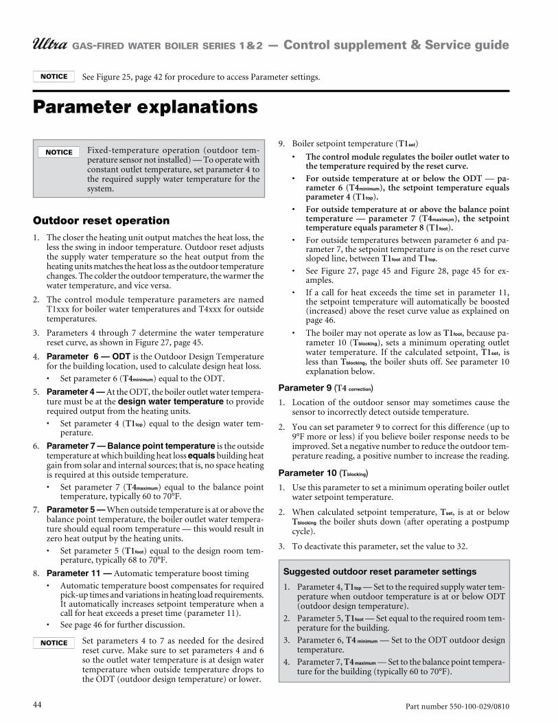
44 Part number 550-100-029/0810
GAS-FIRED WATER BOILER SERIES 1 & 2 — Control supplement & Service guide
Fixed-temperature operation (outdoor tem-perature sensor not installed) — To operate with constant outlet temperature, set parameter 4 to the required supply water temperature for the system.
Outdoor reset operationThe closer the heating unit output matches the heat loss, the 1. less the swing in indoor temperature. Outdoor reset adjusts the supply water temperature so the heat output from the heating units matches the heat loss as the outdoor temperature changes. The colder the outdoor temperature, the warmer the water temperature, and vice versa.
The control module temperature parameters are named 2. T1xxx for boiler water temperatures and T4xxx for outside temperatures.
Parameters 4 through 7 determine the water temperature 3. reset curve, as shown in Figure 27, page 45.
4. is the Outdoor Design Temperature for the building location, used to calculate design heat loss.
Set parameter 6 (T4 ) equal to the ODT.
5. At the ODT, the boiler outlet water tempera-ture must be at the to provide required output from the heating units.
Set parameter 4 (T1 ) equal to the design water tem-perature.
6. is the outside temperature at which building heat loss building heat
is required at this outside temperature.
Set parameter 7 (T4 ) equal to the balance point temperature, typically 60 to 70°F.
7. When outside temperature is at or above the balance point temperature, the boiler outlet water tempera-ture should equal room temperature — this would result in zero heat output by the heating units.
Set parameter 5 (T1 ) equal to the design room tem-perature, typically 68 to 70°F.
8. Automatic temperature boost timing
Automatic temperature boost compensates for required pick-up times and variations in heating load requirements. It automatically increases setpoint temperature when a call for heat exceeds a preset time (parameter 11). See page 46 for further discussion.
Set parameters 4 to 7 as needed for the desired reset curve. Make sure to set parameters 4 and 6 so the outlet water temperature is at design water temperature when outside temperature drops to the ODT (outdoor design temperature) or lower.
Boiler setpoint temperature (9. T1 )
The control module regulates the boiler outlet water to the temperature required by the reset curve.
For outside temperature at or below the ODT — pa-rameter 6 (T4 ), the setpoint temperature equals parameter 4 (T1 ).
For outside temperature at or above the balance point temperature — parameter 7 (T4 ), the setpoint temperature equals parameter 8 (T1 ).
For outside temperatures between parameter 6 and pa-rameter 7, the setpoint temperature is on the reset curve sloped line, between T1 and T1 .
See Figure 27, page 45 and Figure 28, page 45 for ex-amples.
If a call for heat exceeds the time set in parameter 11, the setpoint temperature will automatically be boosted (increased) above the reset curve value as explained on page 46.
The boiler may not operate as low as T1 , because pa-rameter 10 (T ), sets a minimum operating outlet water temperature. If the calculated setpoint, T1 , is less than T , the boiler shuts off. See parameter 10 explanation below.
Parameter 9 (T4 )
1. Location of the outdoor sensor may sometimes cause the sensor to incorrectly detect outside temperature.
2. You can set parameter 9 to correct for this difference (up to 9°F more or less) if you believe boiler response needs to be improved. Set a negative number to reduce the outdoor tem-perature reading, a positive number to increase the reading.
Parameter 10 (T )
1. Use this parameter to set a minimum operating boiler outlet water setpoint temperature.
2. When calculated setpoint temperature, T , is at or below T the boiler shuts down (after operating a postpump cycle).
3. To deactivate this parameter, set the value to 32.
Suggested outdoor reset parameter settings
Parameter 4, 1. T1 — Set to the required supply water tem-perature when outdoor temperature is at or below ODT (outdoor design temperature).
Parameter 5, 2. T1 — Set equal to the required room tem-perature for the building.
Parameter 6, 3. T4 — Set to the ODT outdoor design temperature.
Parameter 7, 4. T4 — Set to the balance point tempera-ture for the building (typically 60 to 70°F).
Parameter explanations
See Figure 25, page 42 for procedure to access Parameter settings.
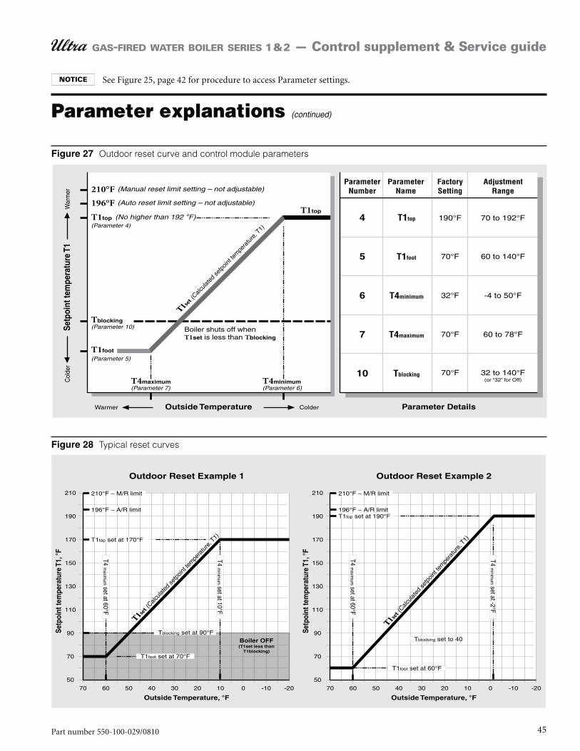
45Part number 550-100-029/0810
GAS-FIRED WATER BOILER SERIES 1 & 2 — Control supplement & Service guide
Outdoor reset curve and control module parameters
Typical reset curves
Parameter explanations (continued)
See Figure 25, page 42 for procedure to access Parameter settings.
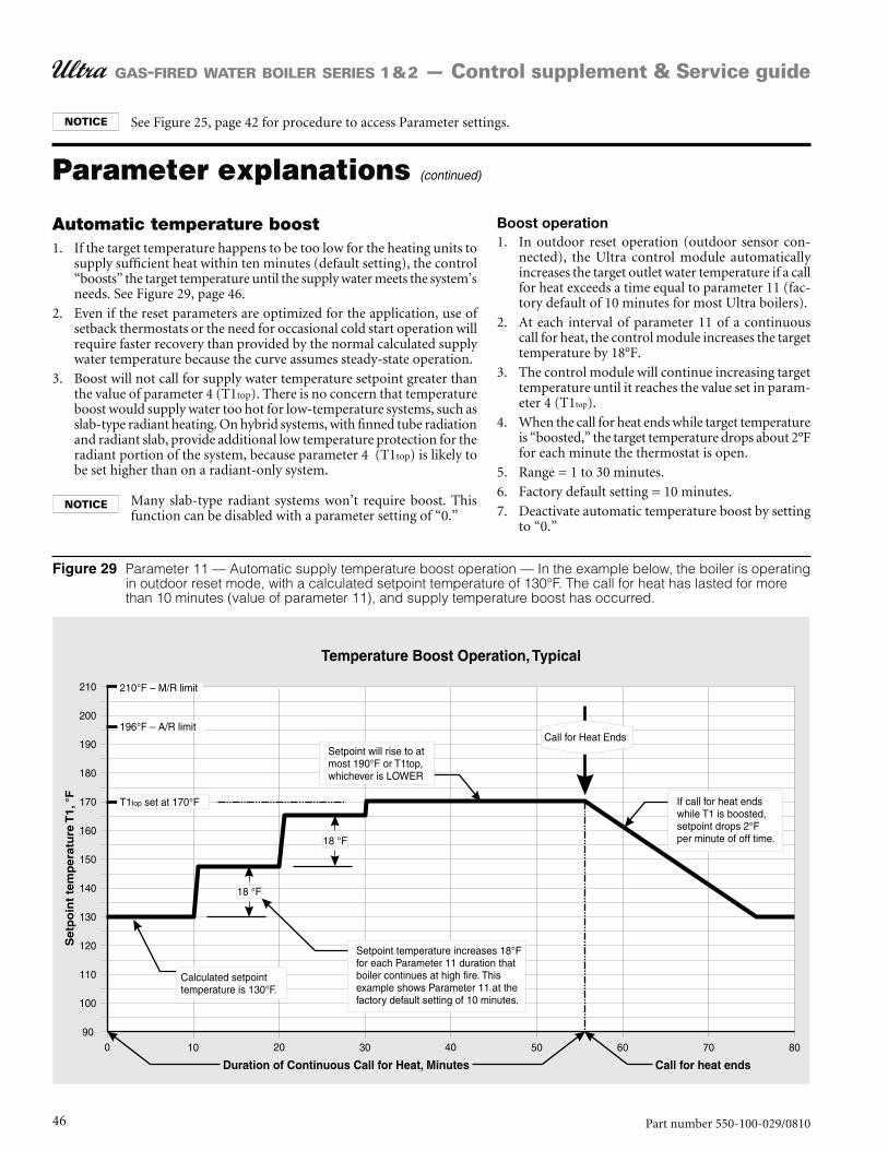
46 Part number 550-100-029/0810
GAS-FIRED WATER BOILER SERIES 1 & 2 — Control supplement & Service guide
Parameter 11 — Automatic supply temperature boost operation — In the example below, the boiler is operating in outdoor reset mode, with a calculated setpoint temperature of 130°F. The call for heat has lasted for more than 10 minutes (value of parameter 11), and supply temperature boost has occurred.
Automatic temperature boost1. If the target temperature happens to be too low for the heating units to
supply sufficient heat within ten minutes (default setting), the control “boosts” the target temperature until the supply water meets the system’s needs. See Figure 29, page 46.
2. Even if the reset parameters are optimized for the application, use of setback thermostats or the need for occasional cold start operation will require faster recovery than provided by the normal calculated supply water temperature because the curve assumes steady-state operation.
3. Boost will not call for supply water temperature setpoint greater than the value of parameter 4 (T1top). There is no concern that temperature boost would supply water too hot for low-temperature systems, such as slab-type radiant heating. On hybrid systems, with finned tube radiation and radiant slab, provide additional low temperature protection for the radiant portion of the system, because parameter 4 (T1top) is likely to be set higher than on a radiant-only system.
Many slab-type radiant systems won’t require boost. This function can be disabled with a parameter setting of “0.”
Boost operation1. In outdoor reset operation (outdoor sensor con-
nected), the Ultra control module automatically increases the target outlet water temperature if a call for heat exceeds a time equal to parameter 11 (fac-tory default of 10 minutes for most Ultra boilers).
2. At each interval of parameter 11 of a continuous call for heat, the control module increases the target temperature by 18°F.
3. The control module will continue increasing target temperature until it reaches the value set in param-eter 4 (T1top).
4. When the call for heat ends while target temperature is “boosted,” the target temperature drops about 2°F for each minute the thermostat is open.
5. Range = 1 to 30 minutes.
6. Factory default setting = 10 minutes.
7. Deactivate automatic temperature boost by setting to “0.”
Parameter explanations (continued)
See Figure 25, page 42 for procedure to access Parameter settings.
47Part number 550-100-029/0810
GAS-FIRED WATER BOILER SERIES 1 & 2 — Control supplement & Service guide
Parameter explanations (continued)
Maximum fan speed1. Parameters 13 and 15 can be set to limit the
maximum boiler firing rate. Boiler firing rate is proportional to the fan speed, so reducing the maximum fan speed reduces maximum input.
2. Reducing maximum fan speed will be helpful for systems on which the boiler is oversized for either space heating or DHW, or both.
3. The maximum fan speed can be set separately for space heating and DHW using parameters 13 and 15.
Parameter 13 — Space heating max fan speed1. Acceptable range:
Ultra-80 to 230: 1300 to 5200 rpm (13 to 52 on boiler display). Ultra-310: 1400 to 5800 rpm (14 to 58 on boiler display).Boiler display shows fan speed in 100’s of rpm. A value of 48 would mean a speed of 100 x 48, or 4800 rpm.
2. Factory default — see Figure 26, page 43.
3. If the boiler is oversized for space heating, you can reduce the maximum fan speed during space heat-ing operation, parameter 13, to limit the maximum boiler input.
Parameter 15 — DHW max fan speed1. Acceptable range:
Ultra-80 to 230: 1300 to 5200 rpm (13 to 52 on boiler display). Ultra-310: 1400 to 5800 rpm (14 to 58 on boiler display).Boiler display shows fan speed in 100’s of rpm. A value of 48 would mean a speed of 100 x 48, or 4800 rpm.
2. Factory default — see Figure 26, page 43.
3. If the boiler is oversized for domestic water heating, you can reduce the maximum fan speed during DHW operation, parameter 15, to limit the maxi-mum boiler input.
The fan speed the value listed in Fig-
ure 30, page 48. This would increase boiler firing rate beyond the accept-able limit, resulting in potential for severe personal injury, death or substantial property damage.
The fan speed the value listed in Fig-
ure 30, page 48. This could result in potential for severe personal injury, death or substantial property dam-age.
— The -
fan speed (parameter 17) and fan speed (parameter 19)
must be set to the values listed in Figure 31, page 49. Failure to comply could result in severe personal injury, death or substantial property dam-age.
Minimum fan speed — parameter 17
1. Parameter 17 sets the minimum fan speed. Boiler firing rate is proportional to fan speed, so increasing the minimum fan speed increases the minimum firing rate (low fire).
2. Parameter 17 sets the minimum fan speed for both DHW and space heating modes.
See Figure 25, page 42 for procedure to access Parameter settings.

48 Part number 550-100-029/0810
GAS-FIRED WATER BOILER SERIES 1 & 2 — Control supplement & Service guide
3. Acceptable range (altitude up to 5,500 feet only):
Ultra-80 to 230: (13 to 52 on boiler display). Ultra-310: (14 to 58 on boiler dis-play).Boiler display shows fan speed in 100’s of rpm. A value of 48 would mean a speed of 100 x 48, or 4800 rpm.
4. Parameter 17 must be increased for applica-tions. See Figure 30, page 48 for required values.
5. Factory default — see Figure 30.
Ignition fan speed — parameter 19
1. Parameter 19 sets the fan speed during ignition. Boiler firing rate is proportional to fan speed, so increasing the minimum fan speed increases the minimum firing rate (low fire).
The ignition fan speed the value in Figure 30). This would reduce boiler fir-ing rate below the acceptable limit during ignition, resulting in potential for severe personal injury, death or substantial property damage.
2. Parameter 19 should as required for applications.
3. Acceptable range (up to 5,500 feet ONLY):
Ultra-80 to 230: (13 to 52 on boiler display).
Ultra-310: (14 to 58 on boiler dis-play).
Boiler display shows fan speed in 100’s of rpm. A value of 27 would mean a speed of 100 x 27, or 2700 rpm.
4. Factory default — see Figure 30.
Parameter explanations (continued)
Firing rates and corresponding blower speeds (low fire, ignition, and high fire) —
> 80 105 155 230 310
RPM RPM RPM RPM RPM
Low fire Minimum fanspeed (up to 5,500 feet) (Factory default setting)
Minimum fanspeed @ (over 5,500 feet)
Ignition Ignition fanspeed (up to 5,500 feet) (Factory default setting)
Ignition fanspeed @ (over 5,500 feet)
High fire
(adjust if desired to match maximum system load — High fire % rate = Max heat load / Boiler output)
Maximum fanspeed CH (parameter 13) (Factory default setting) Applies to
Maximum fanspeed DHW (parameter 14) (Factory default setting) Applies to
See Figure 25, page 42 for procedure to access Parameter settings.
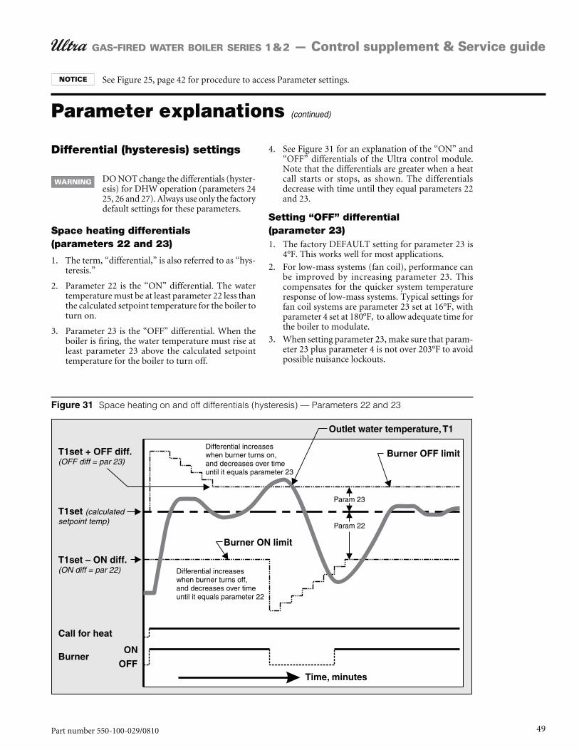
49Part number 550-100-029/0810
GAS-FIRED WATER BOILER SERIES 1 & 2 — Control supplement & Service guide
Space heating on and off differentials (hysteresis) — Parameters 22 and 23
Differential (hysteresis) settings
DO NOT change the differentials (hyster-esis) for DHW operation (parameters 24 25, 26 and 27). Always use only the factory default settings for these parameters.
Space heating differentials (parameters 22 and 23)
1. The term, “differential,” is also referred to as “hys-teresis.”
2. Parameter 22 is the “ON” differential. The water temperature must be at least parameter 22 less than the calculated setpoint temperature for the boiler to turn on.
3. Parameter 23 is the “OFF” differential. When the boiler is firing, the water temperature must rise at least parameter 23 above the calculated setpoint temperature for the boiler to turn off.
4. See Figure 31 for an explanation of the “ON” and “OFF” differentials of the Ultra control module. Note that the differentials are greater when a heat call starts or stops, as shown. The differentials decrease with time until they equal parameters 22 and 23.
Setting “OFF” differential (parameter 23)1. The factory DEFAULT setting for parameter 23 is
4°F. This works well for most applications.
2. For low-mass systems (fan coil), performance can be improved by increasing parameter 23. This compensates for the quicker system temperature response of low-mass systems. Typical settings for fan coil systems are parameter 23 set at 16°F, with parameter 4 set at 180°F, to allow adequate time for the boiler to modulate.
3. When setting parameter 23, make sure that param-eter 23 plus parameter 4 is not over 203°F to avoid possible nuisance lockouts.
Parameter explanations (continued)
See Figure 25, page 42 for procedure to access Parameter settings.
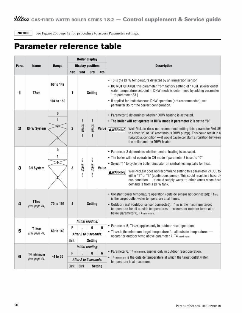
50 Part number 550-100-029/0810
GAS-FIRED WATER BOILER SERIES 1 & 2 — Control supplement & Service guide
Parameter reference table
Para. Name Range
Boiler display
DescriptionDisplay position:
1st 2nd 3rd 4th
1 T3set
68 to 142
104 to 150
1 Setting
DO NOT CHANGE
2 DHW System
0
2
---
Blan
k --
-
---
Blan
k --
-
Value
The boiler will not operate in DHW mode if parameter 2 is set to “0”.
1
2
3
3 CH System
0
3
---
Blan
k --
-
---
Blan
k --
-
Value
1
2
3
4 T1top(see page 44)
70 to 192 4 Setting
5 T1foot(see page 44)
60 to 140
Initial reading:
P . 0 5
After 2 to 3 seconds:
Setting
6 T4 minimum(see page 44)
-4 to 50
Initial reading:
P . 0 6
After 2 to 3 seconds:
Setting
See Figure 25, page 42 for procedure to access Parameter settings.
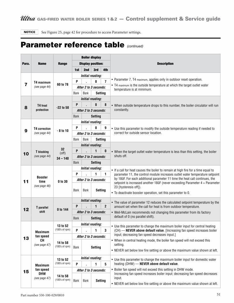
51Part number 550-100-029/0810
GAS-FIRED WATER BOILER SERIES 1 & 2 — Control supplement & Service guide
Parameter reference table (continued)
Para. Name Range
Boiler display
DescriptionDisplay position:
1st 2nd 3rd 4th
7 T4 maximum(see page 44)
60 to 78
Initial reading:
P . 0 7
After 2 to 3 seconds:
Setting
8 T4 frost protection
-22 to 50
Initial reading:
P . 0 8
After 2 to 3 seconds:
Setting
9 T4 correction(see page 44)
- 8 to 10
Initial reading:
P . 0 9
After 2 to 3 seconds:
Setting
10 T blocking(see page 44)
32
34 – 140
Initial reading:
P . 1 0
After 2 to 3 seconds:
Setting
11Booster
time(see page 46)
0 to 30
Initial reading:
P . 1 1
After 2 to 3 seconds:
Setting
12 T parallel shift
0 to 144
Initial reading:
P . 1 2
After 2 to 3 seconds:
Setting
13Maximum fan speed
CH(see page 47)
13 to 52 Initial reading:
NEVER above default valueP . 1 3
14 to 58
After 2 to 3 seconds:
Setting
15Maximum fan speed
DHW(see page 47)
13 to 52 Initial reading:
NEVER above default valueP . 1 5
14 to 58
After 2 to 3 seconds:
Setting
See Figure 25, page 42 for procedure to access Parameter settings.
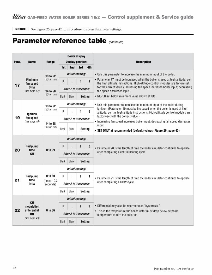
52 Part number 550-100-029/0810
GAS-FIRED WATER BOILER SERIES 1 & 2 — Control supplement & Service guide
Parameter reference table (continued)
Para. Name Range
Boiler display
DescriptionDisplay position:
1st 2nd 3rd 4th
17Minimum fan speed
DHW(see page 47)
13 to 52 Initial reading:
P . 1 7
14 to 58 After 2 to 3 seconds:
Setting
19Ignition
fan speed(see page 48)
13 to 52 Initial reading:
SET ONLY at recommended (default) values (Figure 26, page 43)
P . 1 9
14 to 58 After 2 to 3 seconds:
Setting
20Postpump
time CH
0 to 99
Initial reading:
P . 2 0
After 2 to 3 seconds:
Setting
21Postpump
time DHW
0 to 30
Initial reading:
P . 2 1
After 2 to 3 seconds:
Setting
22
CH modulation differential
ON(see page 49)
0 to 36
Initial reading:
P . 2 2
After 2 to 3 seconds:
Setting
See Figure 25, page 42 for procedure to access Parameter settings.
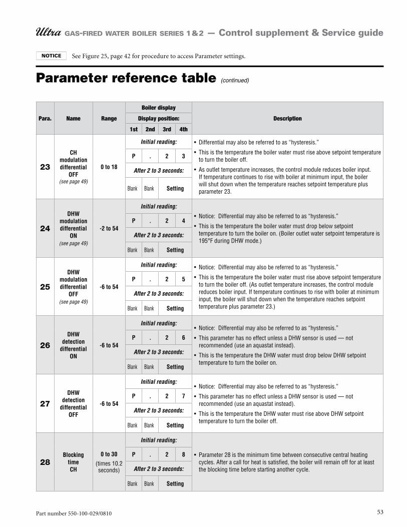
53Part number 550-100-029/0810
GAS-FIRED WATER BOILER SERIES 1 & 2 — Control supplement & Service guide
Parameter reference table (continued)
Para. Name Range
Boiler display
DescriptionDisplay position:
1st 2nd 3rd 4th
23
CH modulation differential
OFF(see page 49)
0 to 18
Initial reading:
P . 2 3
After 2 to 3 seconds:
Setting
24
DHW modulation differential
ON(see page 49)
-2 to 54
Initial reading:
P . 2 4
After 2 to 3 seconds:
Setting
25
DHW modulation differential
OFF(see page 49)
-6 to 54
Initial reading:
P . 2 5
After 2 to 3 seconds:
Setting
26DHW
detection differential
ON
-6 to 54
Initial reading:
P . 2 6
After 2 to 3 seconds:
Setting
27DHW
detection differential
OFF
-6 to 54
Initial reading:
P . 2 7
After 2 to 3 seconds:
Setting
28Blocking
time CH
0 to 30
Initial reading:
P . 2 8
After 2 to 3 seconds:
Setting
See Figure 25, page 42 for procedure to access Parameter settings.

54 Part number 550-100-029/0810
GAS-FIRED WATER BOILER SERIES 1 & 2 — Control supplement & Service guide
Parameter reference table (continued)
Para. Name Range
Boiler display
DescriptionDisplay position:
1st 2nd 3rd 4th
29 Blocking time DHW
0 to 30
Initial reading:
P . 2 9
After 2 to 3 seconds:
Setting
30Blocking
time DHW to CH
0 to 30
Initial reading:
P . 3 0
After 2 to 3 seconds:
Setting
31
T1–T2 difference
for modulating
back
9 to 72
Initial reading:
P . 3 1
After 2 to 3 seconds:
Setting
32 RMCI address
-1
0 to 7 (address)
Initial reading:
DO NOT CHANGEP . 3 2
After 2 to 3 seconds:
Setting
33Tplus
(Setvalue addition for DHW)
0 to 54
Initial reading:
P . 3 3
After 2 to 3 seconds:
Setting
See Figure 25, page 42 for procedure to access Parameter settings.
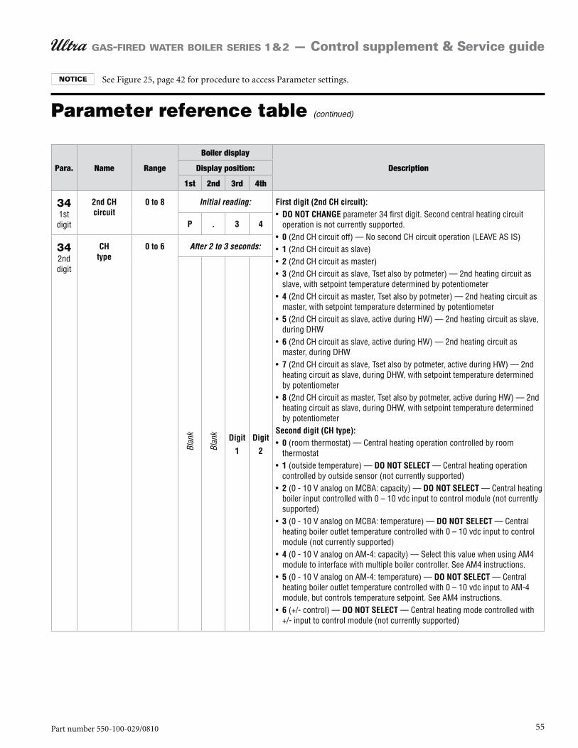
55Part number 550-100-029/0810
GAS-FIRED WATER BOILER SERIES 1 & 2 — Control supplement & Service guide
Parameter reference table (continued)
Para. Name Range
Boiler display
DescriptionDisplay position:
1st 2nd 3rd 4th
34 2nd CH circuit
0 to 8 Initial reading: First digit (2nd CH circuit):DO NOT CHANGE
0123
4
5
6
7
8
Second digit (CH type):0
1 DO NOT SELECT
2 DO NOT SELECT
3 DO NOT SELECT
4
5 DO NOT SELECT
6 DO NOT SELECT
P . 3 4
34 CH type
0 to 6 After 2 to 3 seconds:
Blan
k
Blan
k Digit
1
Digit
2
See Figure 25, page 42 for procedure to access Parameter settings.
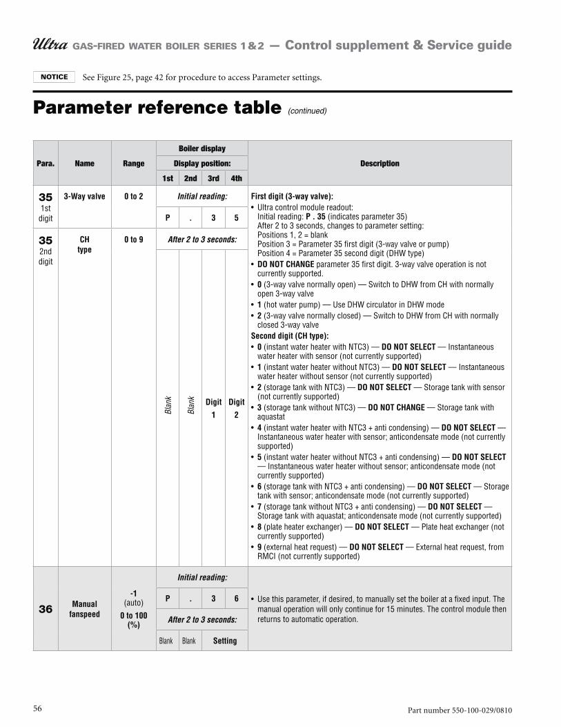
56 Part number 550-100-029/0810
GAS-FIRED WATER BOILER SERIES 1 & 2 — Control supplement & Service guide
Parameter reference table (continued)
Para. Name Range
Boiler display
DescriptionDisplay position:
1st 2nd 3rd 4th
35 3-Way valve 0 to 2 Initial reading: First digit (3-way valve):
P . 35
DO NOT CHANGE
0
12
Second digit (CH type):0 DO NOT SELECT
1 DO NOT SELECT
2 DO NOT SELECT
3 DO NOT CHANGE
4 DO NOT SELECT
5 DO NOT SELECT
6 DO NOT SELECT
7 DO NOT SELECT
8 DO NOT SELECT
9 DO NOT SELECT
P . 3 5
35 CH type
0 to 9 After 2 to 3 seconds:
Blan
k
Blan
k Digit
1
Digit
2
36 Manual fanspeed
-1
0 to 100 (%)
Initial reading:
P . 3 6
After 2 to 3 seconds:
Setting
See Figure 25, page 42 for procedure to access Parameter settings.
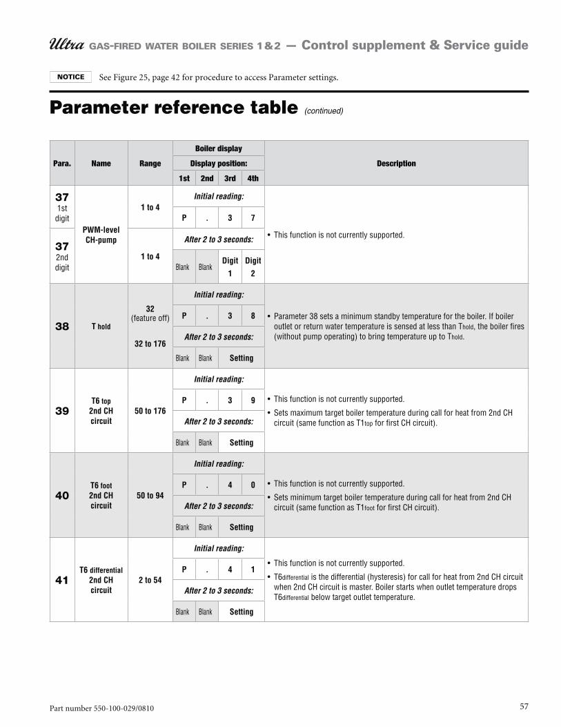
57Part number 550-100-029/0810
GAS-FIRED WATER BOILER SERIES 1 & 2 — Control supplement & Service guide
Parameter reference table (continued)
Para. Name Range
Boiler display
DescriptionDisplay position:
1st 2nd 3rd 4th
37
PWM-level CH-pump
1 to 4Initial reading:
P . 3 7
371 to 4
After 2 to 3 seconds:
Digit
1
Digit
2
38 T hold
32
32 to 176
Initial reading:
P . 3 8
After 2 to 3 seconds:
Setting
39T6 top
2nd CH circuit
50 to 176
Initial reading:
P . 3 9
After 2 to 3 seconds:
Setting
40T6 foot 2nd CH circuit
50 to 94
Initial reading:
P . 4 0
After 2 to 3 seconds:
Setting
41T6 differential
2nd CH circuit
2 to 54
Initial reading:
P . 4 1
After 2 to 3 seconds:
Setting
See Figure 25, page 42 for procedure to access Parameter settings.
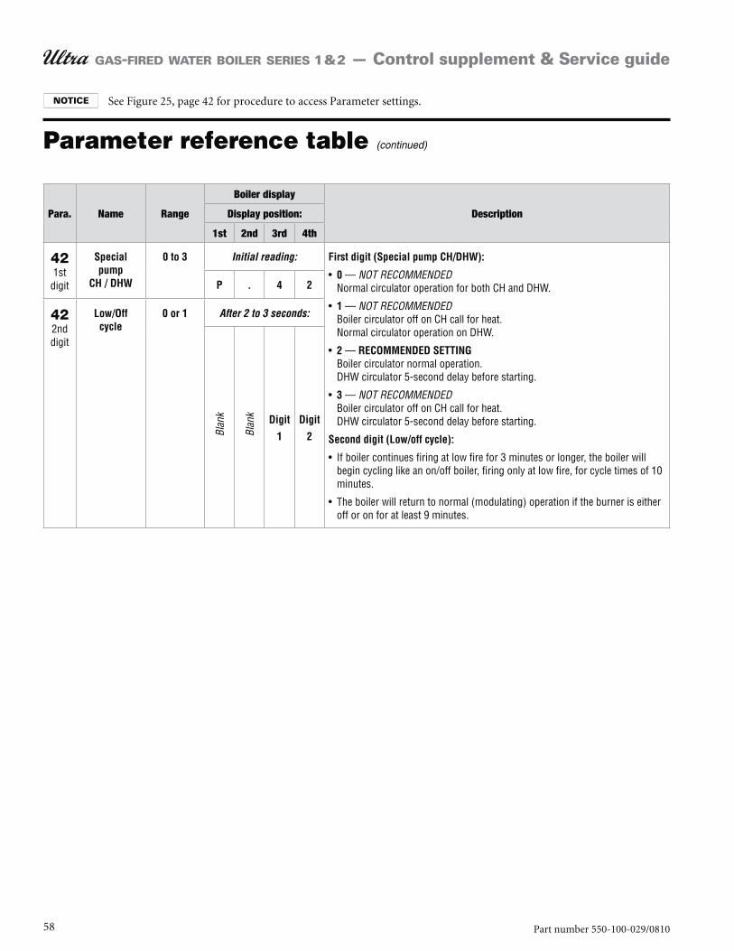
58 Part number 550-100-029/0810
GAS-FIRED WATER BOILER SERIES 1 & 2 — Control supplement & Service guide
Parameter reference table (continued)
Para. Name Range
Boiler display
DescriptionDisplay position:
1st 2nd 3rd 4th
42 Special pump
CH / DHW
0 to 3 Initial reading: First digit (Special pump CH/DHW):
0 NOT RECOMMENDED
1 NOT RECOMMENDED
2 RECOMMENDED SETTING
3 NOT RECOMMENDED
Second digit (Low/off cycle):
P . 4 2
42 Low/Off cycle
0 or 1 After 2 to 3 seconds:
Blan
k
Blan
k Digit
1
Digit
2
See Figure 25, page 42 for procedure to access Parameter settings.
59Part number 550-100-029/0810
GAS-FIRED WATER BOILER SERIES 1 & 2 — Control supplement & Service guide
NOTES
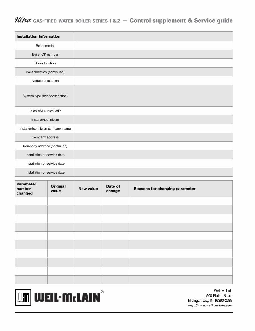
GAS-FIRED WATER BOILER SERIES 1 & 2 — Control supplement & Service guide
Installation information
Boiler model
Boiler CP number
Boiler location
Boiler location (continued)
Altitude of location
System type (brief description)
Is an AM-4 installed?
Installer/technician
Installer/technician company name
Company address
Company address (continued)
Installation or service date
Installation or service date
Installation or service date
Parameter number changed
Original value
New valueDate of change
Reasons for changing parameter