Embed Size (px)
Citation preview
Fatigue of Curved Steel Bridge Elements
ULTIMATE STRENGTH TESTS
OF CURVED COMPOSITE
PLATE GIRDERS
by
R. P. B atchele r
Fritz Engineering Laboratory Report No. 398.b
Fatigue of Curved Steel Bridge Elements
ULTIMATE STRENGTH TESTS OF CURVED COMPOSITE PL~TE GIRDERS
by
Robert P. Batcheler
This work has been carried out as part of an investigation sponsored by the Federal Highway Administration.
Department of Civil Engineering
Fritz Engineering Laboratory #13 Lehigh University
Bethlehem, Pennsylvania 18015
July, 1977
Fritz Engineering Laboratory Report No. 398.b
ii
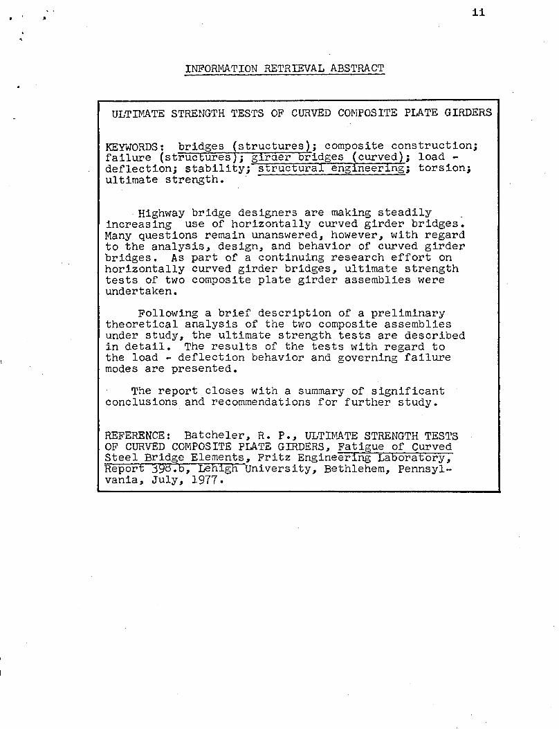
INFORMATION RETRIEVAL ABSTRACT
ULTIMATE STRENGTH TESTS OF CURVED COMPOSITE PLATE GIRDERS
KEYwORDS: bridges (structures); composite construction; failure (structures); girder bridges (curved ; load -deflection; stability; s rue ura eng neer~ng; torsion; ultimate strength •
. Highway bridge designers are making steadily _ increasing use of horizontally curved girder bridges. Many questions remain unanswered, however, with regard to the analysis, design, and behavior of curved girder bridges. As part of a continuing research effort on horizontally curved girder bridges, ultimate strength tests of two composite plate girder assemblies were undertaken.
Following a brief description of a preliminary theoretical analysis of the two composite assemblies under study, the ultimate strength tests are described in detail. The results of the tests with regard to the load - deflection behavior and governing failure modes are presented.
The report closes with a summary of significant conclusions and recommendations for further study.
REFERENCE: Batcheler, R. P., ULTI~~TE STRENGTH TESTS OF CURVED COMPOSITE PLATE GIRDERS, Fatigue of Curved Steel Bridge Elements, Fritz Engineering Laboratory, Report 398.b, Lehigh University, Bethlehem, Pennsylvania, July, 1977.
·'
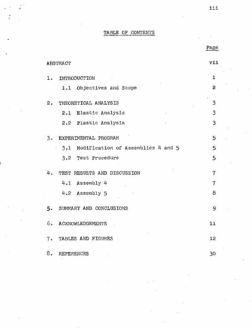
TABLE OF CONTENTS
ABSTRACT
1. INTRODUCTION
1.1 Objectives and Scope
2. THEORETICAL ANALYSIS
2.1 Elastic Analysis
2.2 Plastic Analysis
3 • EXPERIMENTAL PROGRAM
3.1 Modification of Assemblies 4 and 5
3.2 Test Procedure
4. TEST RESULTS AND DISCUSSION
4.1 Assembly 4
4.2 Assembly 5
5· SUMMARY AND CONCLUSIONS
6. ACKNOWLEDGEMENTS
7. TABLES AND FIGURES
8. REFERENCES
iii
Page
vii
1
2
3
3
3
5
5
5
7
7
8
9
11
12
30

...
Table 1
Table 2
LIST OF TABLES
summary of Ultimate Strength Testing Program
summary of Results of Elastic Analysis
iv
v
LIST OF ILLUSTRATIONS
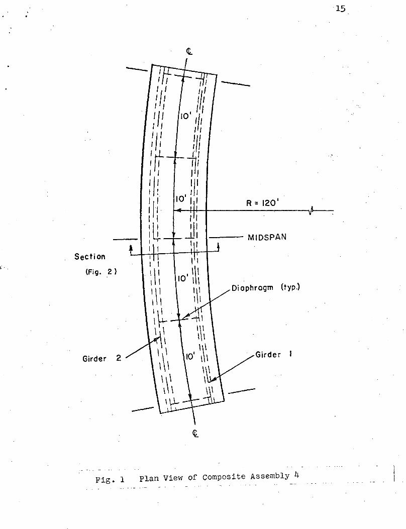
Fig. 1 Plan View of Composite Assembly 4
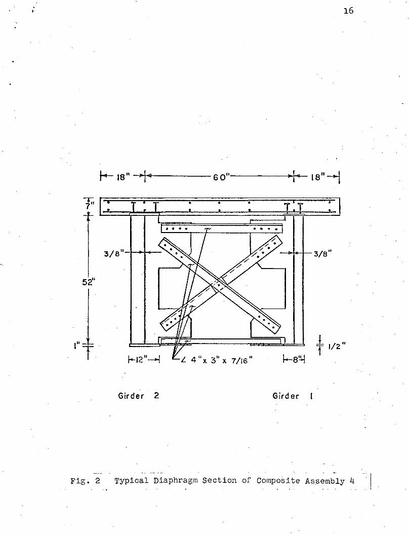
Fig. 2 Typical Diaphragm Section of Composite Assembly 4
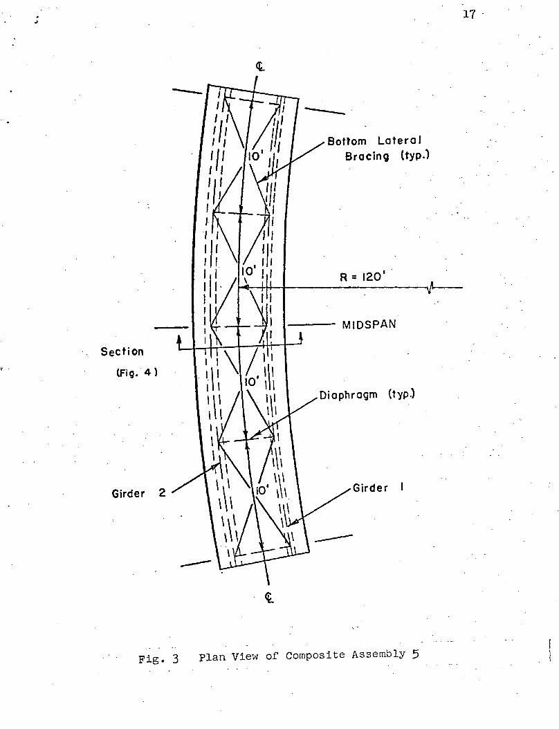
Fig. 3 Plan View of Composite Assembly 5
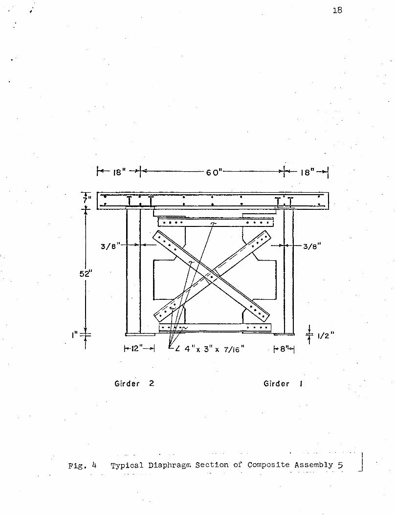
Fig. 4 Typical Diaphragm Section of Composite Assembly 5
Fig. 5 Modification of Plate Girder Assemblies -Addition of Stud Connectors
Fig. 6 Modification of Plate Girder Assemblies -Formwork and Placement of Reinforcing Bars
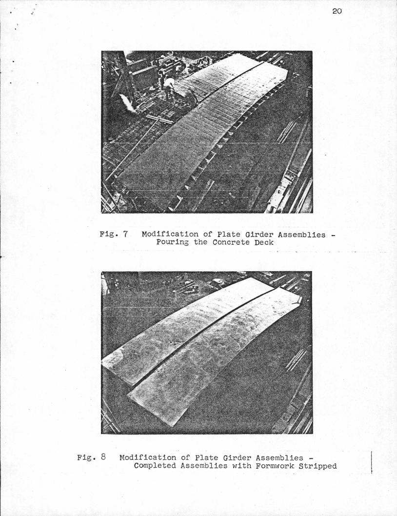
Fig. 7 Modification of Plate Girder Assemblies -Pouring the Concrete Deck
Fig. 8 Modification of Plate Girder Assemblies -Completed Assemblies with Formwork Stripped
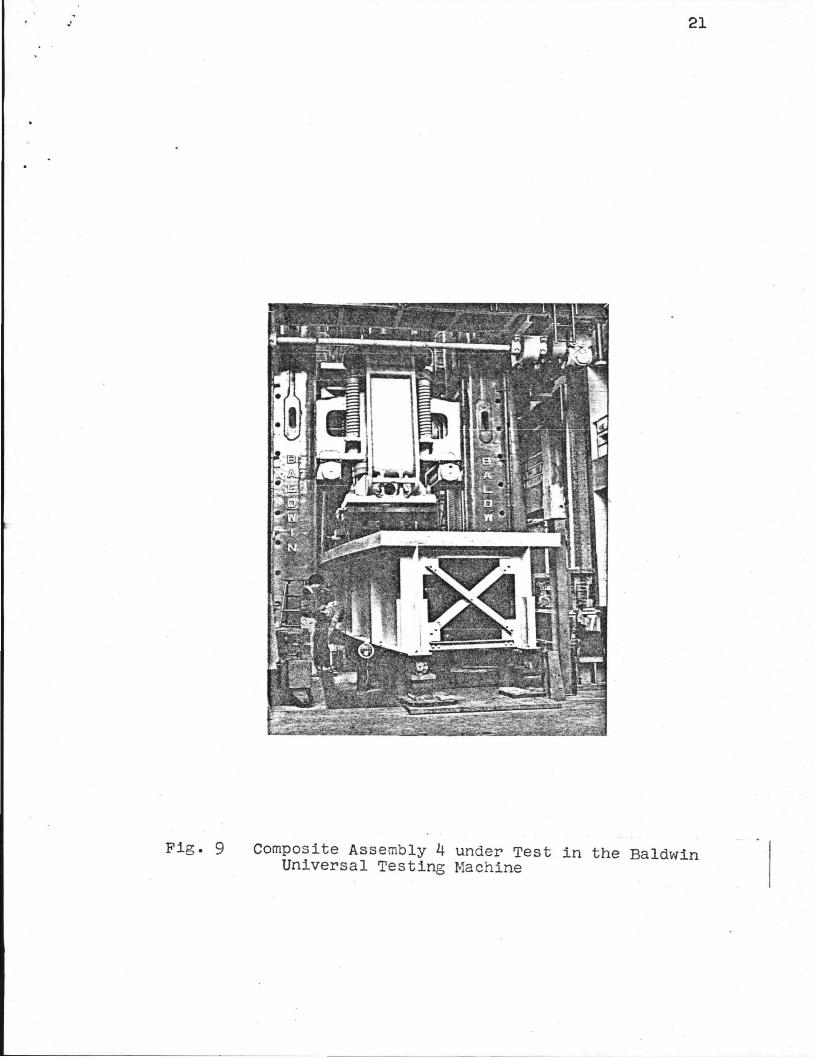
Fig. 9 Composite Assembly 4 under Test in the Baldwin Universal Testing Machine
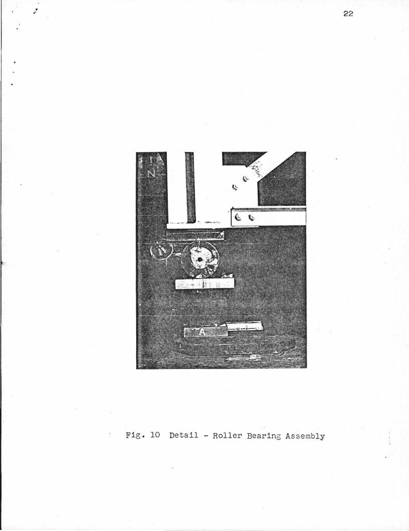
Fig. 10 Detail ~ Roller Bearing Assembly
Fig. 11
Fig. 12
Fig. 13
Fig. 14
Fig. 15
Composite Assembly 4 -Load - Deflection Curve
Composite Assembly 4 (Midspan of Girder 2) -Location of Fracture at Bottom Right
Composite Assembly 4 -Fracture Surface showing Fatigue Crack at Gusset Plate Detail
Composite Assembly 4 -Fracture Surface (schematic)
Composite Assembly 5 -Load - Deflection Curve
Fig. 16. Composite Assembly 5 (Midspan of Girder 1) -Concrete Deck Crushing and Web Buckling under Concentrated Load
Fig. 17 Composite Assembly 5 -Concrete Deck at Midspan Viewed from above
LIST OF ILLUSTRATIONS (cont.)
Fig. 18 Composite Assembly 5 -Midspan Diaphragm and Concrete Deck Viewed from inside the assembly
Fig. 19 Composite Assembly 5 -Midspan Diaphragm Viewed from inside the assembly (looking toward Girder 1)
vi
. ' vii
ABSTRACT
High\'lay bridge designers are making steadily
increasing use of horizontally curved girder bridges. Many
questions remain unanswered, however, with regard to the
analysis, design, and behavior of curved girder bridges.
As part of a continuing research effort on horizontally
curved girder bridges, ultimate strength tests of two
curved composite plate girder assemblies were undertaken.
Following a brief description of a preliminary theo
retical analysis of the two composite assemblies under
study, the ultimate strength tests are described in detail.
The results of the tests with regard to the load -
deflection behavior and governing failure modes are
presented.
The report closes with a summary of significant
conclusions and recommendations for further study.
ULTIMATE STRENGTH TESTS
of
CURVED COMPOSITE PLATE GIRDERS
1. INTRODUCTION
Horizontally curved bridges are often used to simplify
difficult highway alignment problems. The use of curved
girders in such bridges can provide significant advantages
over the use of straight girders as chords of the required
curve. Curved girders are more aesthetically pleasing and
can substantially reduce construction costs. Curved girders
allow longer span lengths, thereby reducing the number of
supports, bearings, and expansion details required. Curved
girders also simplify fornr...rork for the concrete deck
(Thatcher, 1967).
As a result of the increased interest in curved girder
bridges, a major research effort has been underway in the
United States for the past ten years (CURT, 1975; Task
Committee on Curved Girders, 1975; McManus, et al., 1969).
The primary thrust of this work at Lehigh University is
Fritz Laboratory Project 398, Fatigue of Curved Steel Bridge
Elements, sponsored by the Federal Highway Administration.
Project 398 is a four-year, multi-phase investigation
involving extensive analytical and experimental study of the
fatigue of curved girder bridges. Included in the experi
mental study is the fatigue testing of five large-scale
plate girder assemblies. Following the fatigue tests, a
limited ultimate strength testing program was established
in order to obtain as much information as possible from
each large-scale plate girder assembly (Daniels, et al.,
1976; Herbein and Daniels, 1977).
1.1 Objectives and Scope
2
The primary objective of this work is to obtain infor
mation on the ultimate strength behavior of horizontally
curved, composite, plate girder assemblies.
Two composite plate girder assemblies, designated
Assemblies 4 and 5, were tested to failure in Fritz Labora
tory. Plan and section views of Assemblies 4 and 5 are
shown in Figs. 1 through 4. The ultimate strength testing
program is summarized in Table 1.
Following a brief discussion of the theoretical analy
sis of the assemblies under study, the ultimate strength
tests of Assemblies 4 and 5 are described in detail. The
load - deflection behavior and governing failure modes are
presented for both assemblies. The paper closes with a
summary of significant conclusions and recommendations for
further study.
3
2. THEORETICAL ANALYSIS
2.1 Elastic Analysis
The elastic response of the composite assemblies was
established by the finite element method using SAP IV
(Bathe, et al., 1974). The model used in the analysis
contained 166 nodes (876 degrees of freedom), 120 plate
bending elements, 48 beam elements, and 20 truss elements.
More complete information on the finite element analyses
of composite Assemblies 4 and 5 is available (Tedesco and
Batcheler, 1977). The results of the finite element
analyses are summarized in Table 2.
2.2 Plastic Analysis
Models for the determination of the governing failure
modes of curved composite plate girder assemblies are
presently in a rather embryonic stage of development
(Mozer, et.al., 1972). In order to obtain an approximate
value for the ultimate load the assemblies will carry, a
simplified approach was adopted based on simple plastic
theory (Beedle, 1958).
Assuming the steel reaches its yield stress, the
concrete develops 85~ of its specified compressive strength,
and neglecting the small contribution of the bottom lateral
bracing system in Assembly 5, the plastic moment capacity
of Assemblies 4 and 5 is 72 000 kip-in.
The plastic limit load was estimated by assuming the
assemblies are straight 1 with a span length equal to the
centerline span length of the assemblies. The plastic
limit load is thereby estimated by statics to be 600 kips.
A more rigorous analysis of the failure modes and
ultimate strength of the curved composite assemblies is
planned for early next fall.
4
5
3. EXPERIMENTAL PROGRAM
3.1 Modification of Assemblies 4 and 5
Following fatigue tests of Assemblies 4 and ~ all
detected fatigue cracks were repaired. Preparation of the
assemblies proceeded with the addition of the composite
decks indicated in Figs. 2 and 4. Figures 5 through 8 show
the modifications underway in Fritz Laboratory.
3.2 Test Procedure
After the assemblies had cured a minimum of 28 days~
each was tested in the Baldwin universal testing machine
as shown in Fig. 9. The assemblies were loaded by a concen
trated load applied to an essentially rigid (Wl4 x 730)
loading beam. The concentrated load was applied to the
loading beam at a point 9 inches tOi':ard Girder 1 from the
centerline of the assemblies. This eccentricity was
provided because the loading head of the Baldwin machine
has limited rotational capabilities.
The assemblies were supported at both ends of Girders
1 and 2 by roller bearing assemblies shown in Fig. 10.
The bearing assemblies simulate spherical bearings which
only provide resistance to vertical displacements and
rotations about a vertical axis. The loading head of the
Baldwin machine provided stability in the horizontal plane.
6
Instrumentation included 22 dial gages which indicated
horizontal or vertical deflections, and approximately 120
strain gages which were monitored by a B&F Data Acquisition
system. The dial gages and strain gages were read at 50 kip
load increments and the midspan deflections for both Girders
1 and 2 were plotted continuously throughout the test. As
the load - deflection curve departed from linearity,
complete sets of dial gage and strain gage readings were
taken at approximately 1/2 inch increments of midspan
deflection.
The tests were continued to failure of the assemblies
which was considered to be the point at which additional
deflection was accompanied by a drop in the applied load.
,..
7
4. TEST RESULTS AND DISCUSSION
4.1 Assembly 4
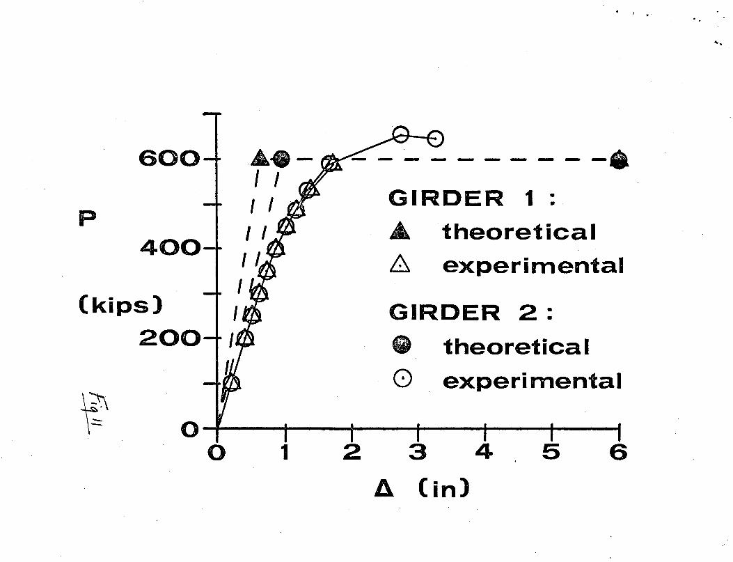
The experimental ·and theoretical load - deflection
behavior of Assembly 4 is shown in Fig. 11~ The midspan
deflections, A, for Girder 1 (the inner girder) and Girder
2 (the outer girder) are shown as a function of the applied
load, P.
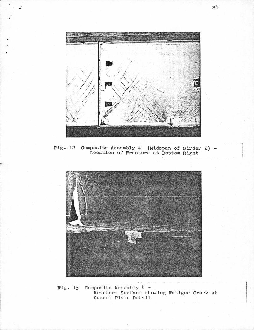
The ultimate strength test of Assembly 4 proceeded
uneventfully to an applied load of approximately 500 kips.
As the applied load passed 500 kips, yield lines began to
develop on the webs and flanges in the manner shown in
Fig. 12. At approximately 600 kips the gage measuring the
vertical deflection of Girde~ 1 ran out of stroke.
Therefore, no subsequent readings could be taken. At
approximately 704 kips an extremely loud report was heard.
Subsequent inspection showed that a previously undetected
fatigue crack at a gusset plate detail had precipitated a
brittle fracture of the tension flange of Girder 2. The
gusset plate detail was located about 3 ft west of midspan
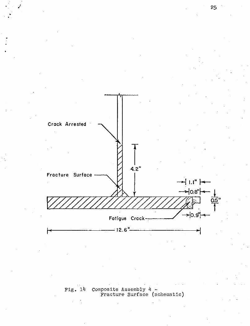
on Girder 2 (Fig. 12). The fracture surface and fatigue
crack are shm'ln in Fig. 13. Figure 14 shows a schematic
view of the fracture surface, establishing the size of the
fatigue crack and the point at which the "running" crack
arrested. The crack arrested only because the flexibility
of the assembly increased due to the fracture, thereby
8
causing the load to drop off. If the load had been applied
by a dead weight testing machine (instead of a displacement
controlled machine like the Baldwin) it is unlikely the
crack would have arrested.
Testing was suspended after the fracture of Girder 2.
4.2 Assembly 5
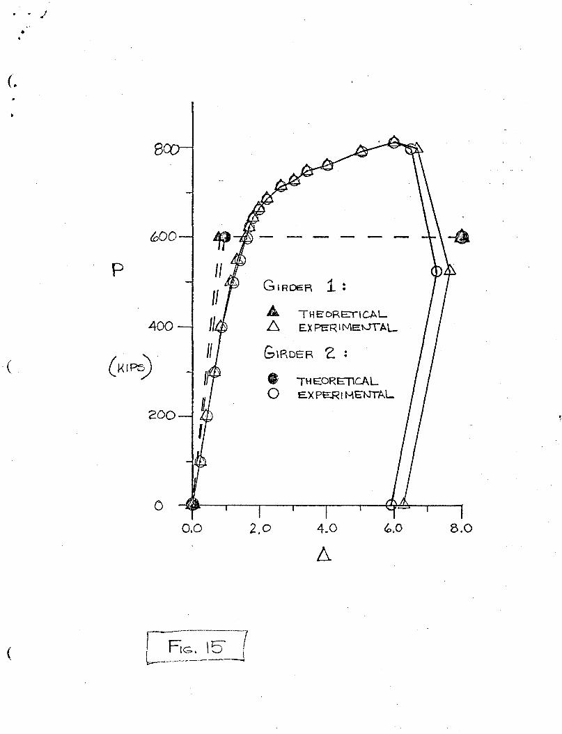
The experimental and theoretical load - deflection
behavior of Assembly 5 is shown in Fig. 15. The midspan
deflections, ~, for Girder 1 and Girder 2 are shown as a
function of the applied load, P.
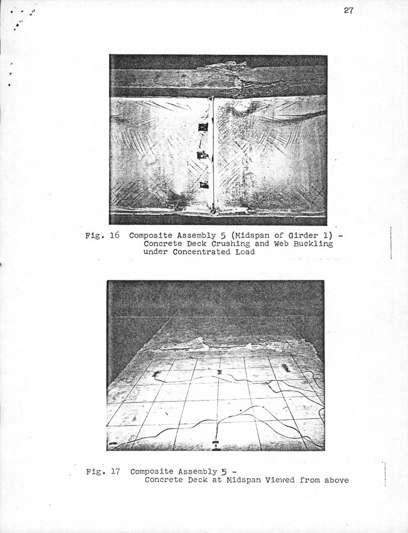
At an applied load of 500 kips yield lines began to
develop in the webs and flanges. At 678 kips small cracks
in the concrete deck and local yielding of the webs under
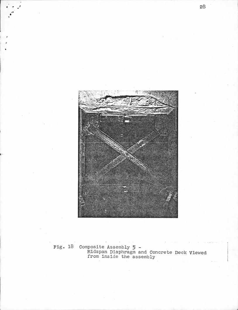
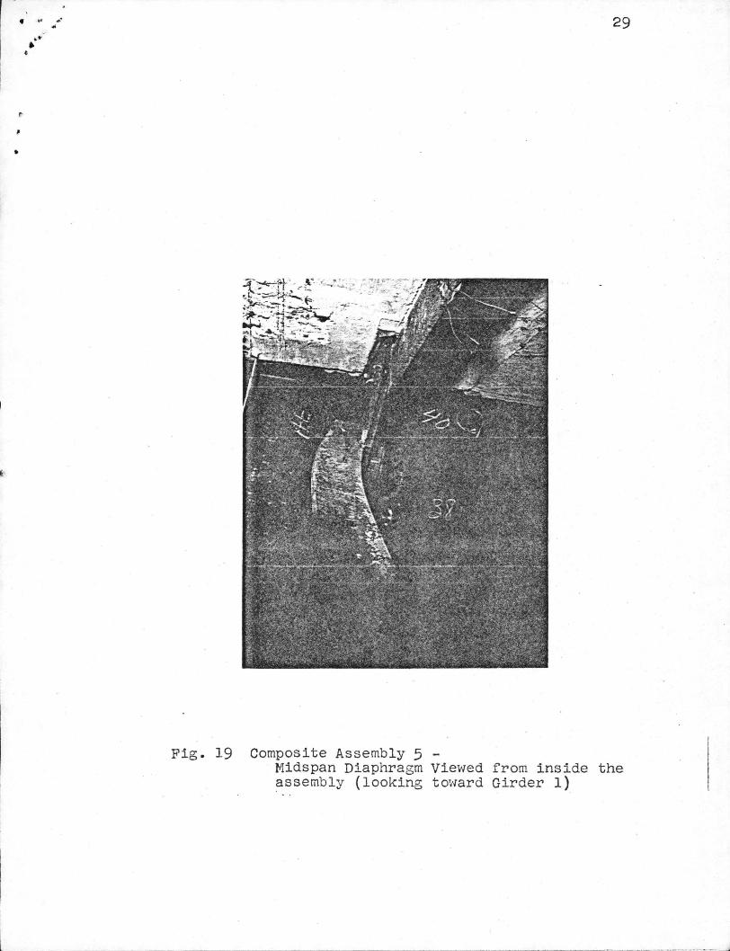
the loading beam were noted. At approximately 830 kips a
loud noise accompanied the buckling of several diaphragm
members. The maximum load sustained by Assembly 5 was
858 kips at which point extensive crushing of the concrete
deck and local buckling of the web caused failure. Figures
16 through 19 show the various elements contributing to the
failure of the assembly.
9
5. SUM!VARY AND CONCLUSIONS
The results of a theoretical and experimental investi
gation of the ultimate strength of curved composite plate
girders are presented. The significant conclusions of this
investigation are as follows:
(1) The theoretical and experimental load -
deflection behavior of Assemblies 4 and 5 is shown in-Figs.
11 and 15, respectively. Relatively poor agreement between
the theoretical and experimental results ~ms observed. The
discrepancies are attributed primarily to the relatively
coarse discretization used for the elastic theoretical
analysis and the gross simplifications introduced in the
plastic theoretical analy_sis.
(2) The governing failure mode for Assembly 4 was
brittle fracture of the tension flange of the outer girder.
Although the crack arrested in the test of Assembly 4, only
the inherent redundancy of most highway bridge structures
would prevent a potentially catastrophic collapse under
extreme service conditions.
(3) The governing failure mode for Assembly 5 was
crushing of the concrete deck and buckling of the webs
under the concentrated load.
Recommendations for further study include:
(1) A refined theoretical analysis of the elastic and
ultimate strength behavior of the composite assemblies
should be undertaken.
10
(2) Reduction of the recorded strain data should be
performed to permit comparison of the measured and theo
retical stresses in the various structural elements.
(3) · Determination of the theoretical value of the
stress intensity at the instant of fracture of Girder 2 in
Assembly 4 should be carried out. Comparison of the
results to the fracture toughness of the material (to be
determined by compact tension testing) would be
enlightening.
t_
11
6. ACKNO\>TLEDGEf.lENTS
This study was conducted at the Fritz Engineering
Laboratory, Department of Civil Engineering, at Lehigh
University. Dr. L. s. Beedle is Director of Fritz
Engineering Laboratory, and Dr. D. A. VanHorn is Chairman
of the Department of Civil Engineering.
This study was undertaken as part of a multi-phase
investigation entitled, 11Fatigue of Curved Steel Bridge
Elements". Dr. J. H. Daniels is the Principal Investigator.
The sponsor is the Federal High~·1ay Administration (FHWA),
United States Department of Transportation. The FHWA
Project Y..1anager is r1r. Jerar Nishanian.
The contributions of the Lehigh Project Advisory Panel
are gratefully acknowledged. The Advisory Panel members
are:Messrs: A. P. Cole, c. G. Culver, R. s. Fountain,
G. F. Fox, A. Lally, and I. M. Viest.
The following members of the faculty and staff of
Lehigh University made major contributions to the conduct
of this work: Dr. J. w. Fisher, Dr. B. T. Yen, Dr. R. G.
Slutter, w. c. Herbein, D. Abraham, R. Dales, and R.
Langenbach.

12
7. TABLES AND FIGURES
13
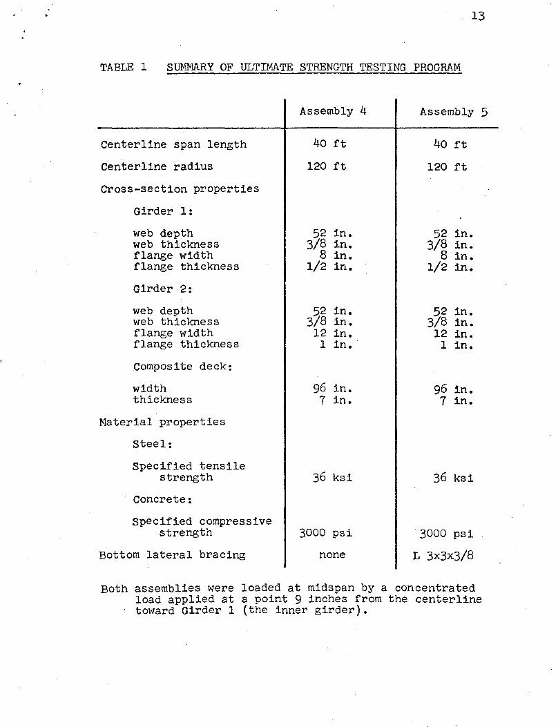
TABLE 1 SUMMARY OF ULTIMATE STRENGTH TESTING PROGRAM
Centerline span length
Centerline radius
Cross-section properties
Girder 1:
web depth web thickness flange width flange thickness
Girder 2:
web depth ~reb thickness flange width flange thickness
Composite deck:
width thickness
Material properties
steel:
Specified tensile strength
Concrete:
Specified compressive strength
Bottom lateral bracing
Assembly 4
40 ft
120 ft
52 in. 3/8 in.
8 in. 1/2 in.
52 in. 3/8 in.
12 in. 1 in.·
96 in. 7 in.
36 ksi
3000 psi
none
Assembly 5
40 ft
120 ft
52 in. 3/8 in.
8 in. 1/2 in.
52 in. 3/8 in.
12 in. 1 in.
96 in. 7 in.
36 ksi
3000 psi
L 3x3x3/8
Both assemblies were loaded at midspan by a concentrated load applied at a point 9 inches from the centerline tm'lard Girder 1 (the inner girder) •
' •
~-·
14
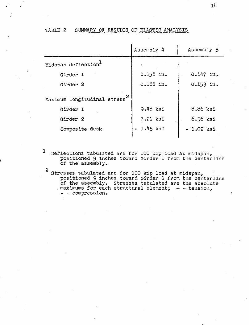
TABLE 2 SUMMARY OF RESULTS OF EL~STIC ANALYSIS
Assembly 4 Assembly 5
Midspan deflection1
Girder 1 0.156 in. 0.147 in.
Girder 2 0.166 in. 0.153 in.
Maximum longitudinal stress 2
Girder 1 9.48 ksi 8.86 ksi
Girder 2 7.21 ksi 6.56 ksi
Composite deck - 1.45 ksi - 1.02 ksi
1 Deflections tabulated are for 100 kip load at midspan, positioned 9 inches toward Girder 1 from the centerline of the assembly.
2 Stresses tabulated are for 100 kip load at midspan, positioned 9 inches toward Girder 1 from the centerline of the assembly. Stresses tabulated are the absolute maximums for each structural element; + = tension, - = compression.
--- I I I I I
It' t I I II I I
I I I lfl 10 ,,, I I
'I' I I
'I' I I I f
w ~I I I I I I
I I' 'l' I ! I I I I I 10 I I A= 120
1 ,,, I I I~ I I MIDSPAN I I
I I Section I I
I. (Fig. 2)
1 1\1 10 I I
I\ I Di ophrogm (typ.)
I I
Girder 2 Girder
---Fig. 1 Plan View of Composite Assembly 4
16
r.-- 1s" -)>)>ofl~llil----- s o~~----~-c-- 18 11 __,
• •
3 I 8 11-1---.5--
52"
L 411
x 3"x 7/1611
Girder 2
Fig. 2 Typical Diaphragm Section of
---1......-+- 3/8 II
Girder
1 1/2" T
Composite Assembly 4 - ··: I - - . l
.. Section
(Fig. 4)
Girder 2
I I
't' I I I I
lfl I I
'I' I I I I· I I
'I' I I I I Ill· I I I I
Bottom Latera I Brae in g (typ.)
R = 120' .
Diaphragm (typ.)
Girder I
Fig. 3 Plan View of Composite Assembly 5
17.
18
t+- 18 II _,,.~1-+lli -....---- 6 o"----+JI' Mr'-- I 8 n _,
3 Is"-+-~-- ~>4+--J.- 3/8 ..
1 J/2" T 7/16 II
Girder 2 Girder
Fig. 4 Typical Diaphragm Section of Composite Assembly 5
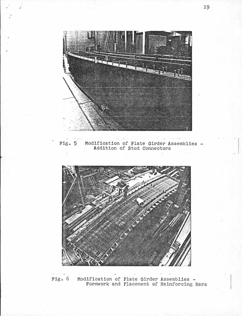
Fig. 5
Fig. 6
Modification of Plate Girder Assemblies -Addition of Stud Connec-tors
19
Modification of Plate Girder Assemblies -Formwork and Placement of Reinforcing Bars
I
20
Fig. 7 Modification of Plate Girder Assemblies -Pouring the Concrete Deck
Fig. 8 Modification of Plate Girder Assemblies -Completed Assemblies with Formwork Stripped
. '
Fig. 9
21
Composite Assembly 4 under Test in the Baldwin Universal Testing Machine
• ..
Fig. 10
22
Detail - Roller Bearing Assembly
600
p
(kips)
200
• I •
A-8- ~ ..... ~- - - - - - - - - -· I I I I GIRDER 1 :
• theoretical
8 experimental
GIRDER 2:
8 theoretica I
0 ex peri mental
0~--_.--~~--+---~---T--~ 0 1 2 3 4 5 6
11 (in)
...

23
(Prepared as original for slide.)
Fig. 11 Composite Assembly 4 - Load-Deflection Curve
-------- ----~----------------------,
24
•• . I- ,. .· .r .r ./ -
'
Fig.·l2 Composite Assembly 4 (Midspan of Girder 2) -Location of Fracture at Bottom Right
Fig. 13 Composite Assembly 4 -Fracture Surface showing Fatigue Crack at Gusset Plate Detail
• . . /
Crack Arrested
4.2" Fracture Surface --
Fatigue Crock-----.J
25
~ 1.111 ~
~0.811~ l_ 05 11
. T ->{o. s''}-t-
~------------------· 12.611
--------------------~
Fig. 14 Composite Assembly 4 -Fracture Surface (schematic)
•
8
p
(
0
0.0
(
GIRDER 1:
J.\. THEDRETIC..AL ~ EXPERIMEWTAL.
G\RDER '2. :
8 IHEORE11c.A.L 0 E.XPE.RIMEtJrAL
2,0 4.0 8.0

~ • .J' 26
•
(Prepared for drafting room.)
Fig. 15 Composite Assembly 5 - Load-Deflection Curve
• • ··1 .. •' ..
I •
Fig. 16 Composite Assembly 5 {Midspan of Girder 1) -Concrete Deck Crushing and Web Buckling under Concentrated Load
Fig. 17 Composite Assembly 5 -
27
Concrete Deck at Midspan Viewed from above
• ~ .1 ~ 28
Fig. 18 Composite Assembly 5 -Midspan Diaphragm and Concrete Deck Viewed from inside the assembly
/ ... • 29
Fig. 19 Composite Assembly 5 -Midspan Diaphragm Viewed from inside the assembly (looking toward Girder 1)
..
• r,' •.'
• .> ... •
• 30
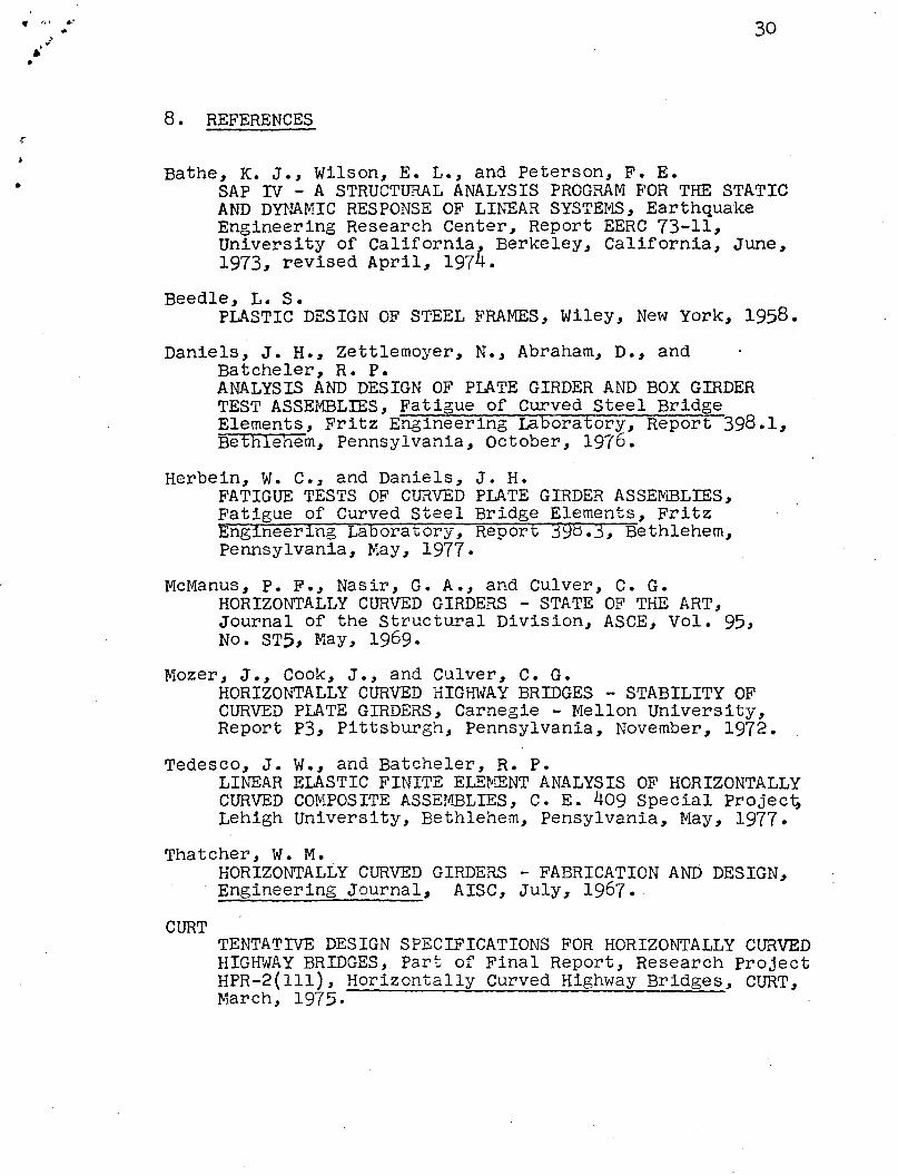
8 • REFERENCES
Bathe, K. J., Wilson, E. L., and Peterson, F. E • SAP Dl - A STRUCTURAL ANALYSIS PROGRAN FOR THE STATIC AND DYNAr.'IIC RESPONSE OF LI~'EAR SYSTEI'ILS, Earthquake Engineering Research Center, Report EERC 73-11, University of California, Berkeley, California, June, 1973, revised April, 1974.
Beedle, L. S. PLASTIC DESIGN OF STEEL FRAMES, Wiley, New York, 1958.
Daniels, J. H., Zettlemoyer, N., Abraham, D., and Batcheler, R. P. ANALYSIS AND DESIGN OF PLATE GIRDER AND BOX GIRDER TEST ASSEMBLIES, Fatigue of Curved Steel Bridge Elements, Fritz Engineering Laboratory, Report 398.1, Bethlehem, Pennsylvania, October, 1976.
Herbein, w. c., and Daniels, J. H. FATIGUE TESTS OF CURVED PLATE GIRDER ASSE~ffiLIES, Fatigue of Curved Steel Bridge Elements, Fritz Engineering Laoorauory, Report 398.3, Bethlehem, Pennsylvania, May, 1977.
Mcr~anus, P. F., Nasir, G. A., and Culver, C. G. HORIZONTALLY CURVED GIRDERS - STATE OF THE ART, Journal of the Structural Division, ASCE, Vol. 95, No. STS, May, 1969.
Mozer, J., Cook, J., and Culver, c. G. HORIZONTALLY CURVED HIGID~AY BRIDGES - STABILITY OF CURVED PLATE GIRDERS, Carnegie - Mellon University, Report P3, Pittsburgh, Pennsylvania, November, 1972.
Tedesco, J. w., and Batcheler, R. p. LINEAR ELASTIC FINITE ELEIVIENT ANALYSIS OF HORIZONTALLY CURVED CO~IPOSITE ASSEII!BLIES, C. E. 409 Special Project; Lehigh University, Bethlehem, Pensylvania, May, 1977.
Thatcher, w. M.
CURT
HORIZOt-.J"TALLY CURVED GIRDERS - FABRICATION AND DESIGN, Engineering Journal, AISC, July, 1967.
TENTATIVE DESIGN SPECIFICATIONS FOR HORIZONTALLY CURVED HIGFdAY BRIDGES, Part of Final Report, Research Project HPR-2(111), Horizontally Curved Highway Bridges, CURT, March, 1975.

• • I ' t4
.}
r
•
i' ~\
..... 31
Task Committee on Curved Girders CURVED GIRDER SPECIFICATIONS AND RESEARCH SUMMARY, ASCE - AASHTO Committee on Flexural Members, Structural Division, ASCE, 197~ .


![[10] Buckling and Ultimate Strength](https://img.pdfslide.us/doc/110x75/577cdce11a28ab9e78aba484/10-buckling-and-ultimate-strength.jpg)