Embed Size (px)
Citation preview

Mechanical Devices Ltd, www.mechanical-devices.com | [email protected] DOC 14000014-7 REV G 01/03/16
1
ULTIMATE POWER TEMPERATURE FORCING SYSTEM
FOR THERMAL CYCLING OF DUT
FROM -65°C to +175°C
60W @ -45⁰C / 200W @ 0⁰C
Rapid Cooling & Heating Rates
For MaxTC firmware 1.8.6 and higher
User Guide October 2015

Mechanical Devices Ltd, www.mechanical-devices.com | [email protected] DOC 14000014-7 REV G 01/03/16
2
Table of Contents
MaxTC Overview 3
Basic Information about the MaxTC system
4
Thermal Head 4
MaxTC User Interface 5
MaxTC System Back Panel 8
Supplied Accessories 9
MaxTC Interface Options 10
Custom Adapter Plate 10
Universal Adapter Plate 10
Torque Wrench 10
Boom Stand Arm 11
Thermocouple Inserted Lids 11
Open Frame Thermal Lid 11
Pneumatic Head Assembly 11
Vacuum Quick Connect Mechanism 12
Specifications 13
Operation 14
Connecting the Adapter Plate 14
Installing Plunger in the Thermal Head
15
Changing Plungers 15
Setting Plunger Parameters 16
Auto Tune Procedure 16
Installing the Thermal Head on the Adapter Plate
17
Activating the MaxTC 18
Initial Activation of MaxTC & Temporary Activation Code Instructions
18
Permanent Activation Code 18
Warranty / Calibration Codes 19
Setting Temperature 20
Set Point Temperature 20
Setting Incremental Rates 21
Setting Presets 21
Setting Thermocouple [K-Type] 21
Setting a Ramp/Soak Sequence 22
Using The Offset Table 23
Using a Remote Computer 25
Setting up Remote Connection 25
Entering Commands in Hyper Terminal
28
Registrar Maps 29
Offset Window Registrar Maps 29
Manual Control Screen Registrar Map 30
System Setting Registrar Map 31
Profile Screen Registrar Map 32
Remote Junction temperature control 33
Troubleshooting 34
Fault Indication 34
MaxTC Fault Handling 34
Fan 34
Hot Side 34
Cold Side 34
High Pressure 34
Plunger Troubleshooting 35
Communication Problems with MaxTC
36
MaxTC Technology 39
System Overview 39
Benefits of Fluid Free Operation 39
Facilities Free Operation 39
Cooling Power 39
Thermal Loads 39
Settling Time 40
MaxTC Is Ideal For Handlers Integration in Many Ways
40
MaxTC Ready Sockets Lids 40
Mechanical Devices Sockets Support 40
Humidity & Frost Free Operation 41
FAQ 44
Mechanical Devices World Map 46
Contact Us 46
Mechanical Devices Ltd, www.mechanical-devices.com | [email protected] DOC 14000014-7 REV G 01/03/16
3
Thermal Head Hose
Thermal Head
MaxTC Device Plunger
Front Panel Purge
7” Touch screen
MaxTC Overview
MaxTC Temperature Forcing System is used for stimulating case temperature (T case) by direct contact between a thermal head’s plunger and DUT.
MaxTC Temperature Forcing System’s main components:
1. Thermal head
2. Thermal head hose
3. Touchscreen user interface
4. Front panel purge
5. Device plunger
6. Mechanical interface: Thermal head makes direct mechanical contact with soldered or socketed DUT using one of the following interface options:
a. Universal adapter plate (suitable for socketed, open-top, soldered DUTs)
b. Custom adapter plate (suitable for socketed and soldered DUTs)
c. Boom stand arm (suitable for open-top, soldered DUTs)
d. Thermocouple inserted lid (suitable for open-top, socketed DUTs)
e. Open frame thermal lid (suitable for socketed, soldered DUTs)
f. Pneumatic head assembly (for quick replacement of devices in sockets)
g. Vacuum quick connect mechanism (for quick replacement of devices in sockets)

Mechanical Devices Ltd, www.mechanical-devices.com | [email protected] DOC 14000014-7 REV G 01/03/16
4
Basic information about the MaxTC system
Thermal Head
Temperature stimulation of the DUT is accomplished by plunger installed into the thermal head of the MaxTC. The plunger is installed into the thermal head with the help of four mounting pins and two retaining screws. The thermal head with the plunger inside is then positioned to be in direct contact with the DUT. The changes in temperature are passed from plunger to DUT by direct conduction. The plunger contains a Thermal Sensor (PT100) which makes 30 measurements per second. The sensor data is further transmitted to the MaxTC system which, in turn, makes 30 adjustments per second to the heating/cooling of the plunger in order to guarantee the ±0.2°C temperature accuracy on the DUT.
The thermal head also has 4 Purge Nozzles for the purpose of introduction of Nitrogen or dry air in the thermal head via the access line connected to the unit’s back panel. The constant supply of Nitrogen or dry air flow creates a frost and humidity free shield around the DUT. A software operated solenoid automatically activates the dry air purge when the testing temperature drops below 16°C. The dry air flow is diverted away from the test area in order to avoid unwanted thermal loss.
Note: Heating coils prevent condensation on the thermal head cover.
For testing devices in sockets the thermal head is mounted using the adapter plate. For soldered and open-top DUT’s the thermal head is mounted directly onto the board.
Mechanical Devices Ltd, www.mechanical-devices.com | [email protected] DOC 14000014-7 REV G 01/03/16
5
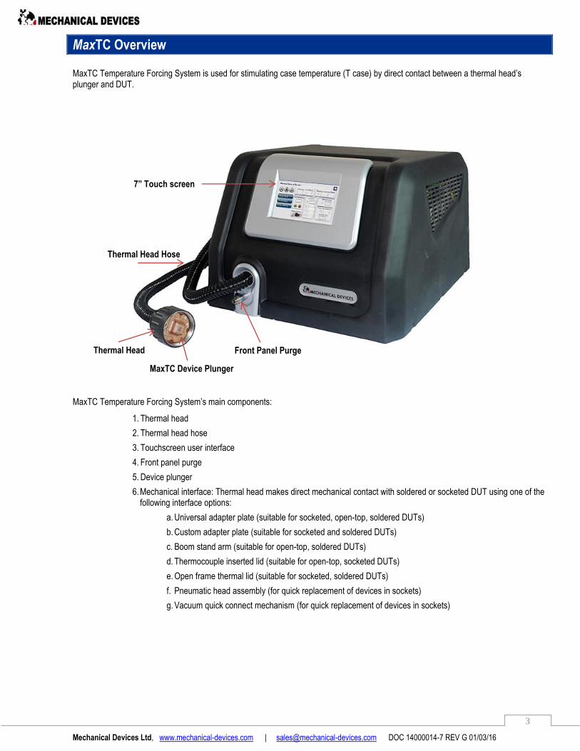
MaxTC User Interface
MaxTC operations are controlled by an LCD touchscreen located on the front of the unit.
Commands are entered to the unit by pressing the appropriate input field. There are four user screens. To activate press one of the following:
Home – Displays the Manual Control Screen for entering system parameter settings.
Activate – Displays the screen for activating the unit.
Offline - not connected to the LAN cable
Online - the system is communicating with PC
LAN cable - connected to LAN cable through the rear panel
The Manual Control Screen has three sub-screens that can be accessed by selecting buttons located on the left:
Displays the Offset Window. You may program up to 3 offset tables.
Display a screen for entering the settings of the Ramp/Soak routine.
Activates a screen for entering certain screen parameters.
Mechanical Devices Ltd, www.mechanical-devices.com | [email protected] DOC 14000014-7 REV G 01/03/16
6
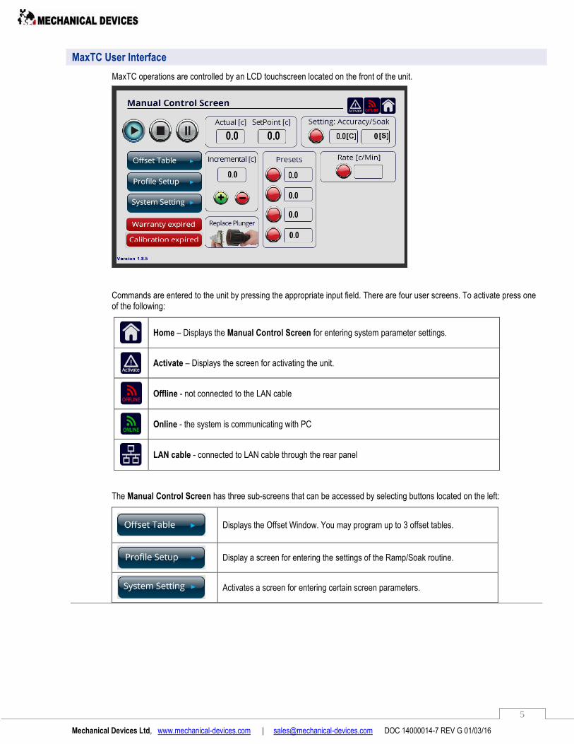
Number Keypad
A number keypad is displayed on an input field:
Numbers are entered by pressing the appropriate key. In addition the following keys are available:
Clear all input.
Clears last digit entered.
For negative numbers enters a minus sign.
Accepts the value entered in the input field and clears the number keypad.
Closes the number keypad without entering any value.
Operational Buttons
Play Button: MaxTC is in operational mode.
Stop Button: Acts as a Standby mode. MaxTC is off but it can be activated immediately via touchscreen or PC.
Pause Button: MaxTC continues to operate at ambient temperature (25⁰C). This mode is used for
switching devices.
Return Button: It appears when you are in one of the sub- screens. Pressing this button returns you to the TC Control Screen.
Please note – It is recommended to switch off the MaxTC at the back panel if not used daily, but if you are going to use it the next day you can switch the unit to standby mode (Stop button).
Mechanical Devices Ltd, www.mechanical-devices.com | [email protected] DOC 14000014-7 REV G 01/03/16
7
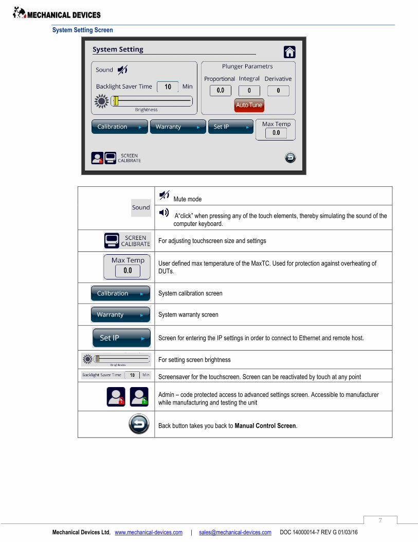
System Setting Screen
Mute mode
A“click” when pressing any of the touch elements, thereby simulating the sound of the computer keyboard.
For adjusting touchscreen size and settings
User defined max temperature of the MaxTC. Used for protection against overheating of DUTs.
System calibration screen
System warranty screen
Screen for entering the IP settings in order to connect to Ethernet and remote host.
For setting screen brightness
Screensaver for the touchscreen. Screen can be reactivated by touch at any point
Admin – code protected access to advanced settings screen. Accessible to manufacturer while manufacturing and testing the unit
Back button takes you back to Manual Control Screen.
Mechanical Devices Ltd, www.mechanical-devices.com | [email protected] DOC 14000014-7 REV G 01/03/16
8
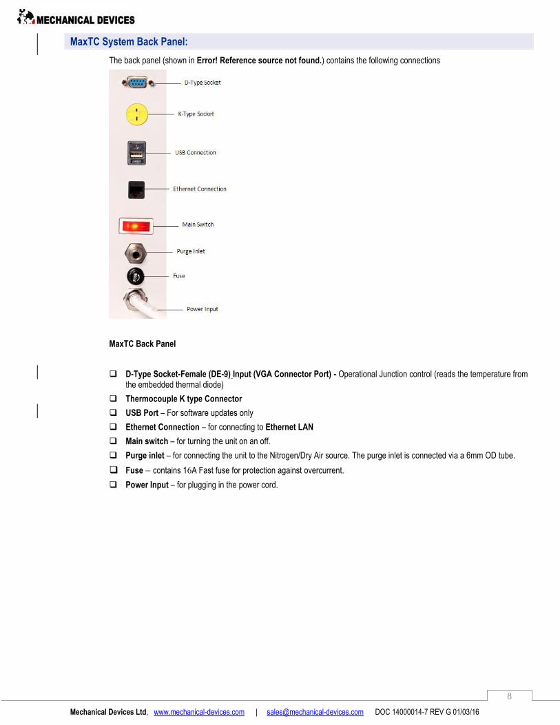
MaxTC System Back Panel:
The back panel (shown in Error! Reference source not found.) contains the following connections
MaxTC Back Panel
D-Type Socket-Female (DE-9) Input (VGA Connector Port) - Operational Junction control (reads the temperature from the embedded thermal diode)
Thermocouple K type Connector
USB Port – For software updates only
Ethernet Connection – for connecting to Ethernet LAN
Main switch – for turning the unit on an off.
Purge inlet – for connecting the unit to the Nitrogen/Dry Air source. The purge inlet is connected via a 6mm OD tube.
Fuse – contains 16A Fast fuse for protection against overcurrent.
Power Input – for plugging in the power cord.
Mechanical Devices Ltd, www.mechanical-devices.com | [email protected] DOC 14000014-7 REV G 01/03/16
9
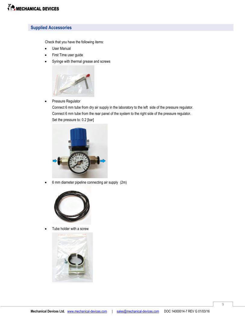
Supplied Accessories
Check that you have the following items:
User Manual
First Time user guide
Syringe with thermal grease and screws
Pressure Regulator
Connect 6 mm tube from dry air supply in the laboratory to the left side of the pressure regulator.
Connect 6 mm tube from the rear panel of the system to the right side of the pressure regulator.
Set the pressure to: 0.2 [bar]
6 mm diameter pipeline connecting air supply (2m)
Tube holder with a screw
Mechanical Devices Ltd, www.mechanical-devices.com | [email protected] DOC 14000014-7 REV G 01/03/16
10
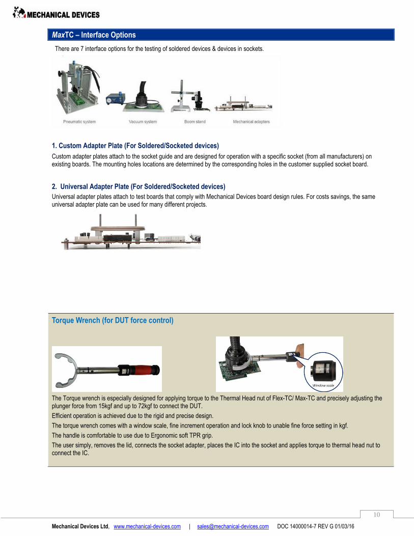
MaxTC – Interface Options
There are 7 interface options for the testing of soldered devices & devices in sockets.
1. Custom Adapter Plate (For Soldered/Socketed devices)
Custom adapter plates attach to the socket guide and are designed for operation with a specific socket (from all manufacturers) on existing boards. The mounting holes locations are determined by the corresponding holes in the customer supplied socket board.
2. Universal Adapter Plate (For Soldered/Socketed devices)
Universal adapter plates attach to test boards that comply with Mechanical Devices board design rules. For costs savings, the same universal adapter plate can be used for many different projects.
Torque Wrench (for DUT force control)
The Torque wrench is especially designed for applying torque to the Thermal Head nut of Flex-TC/ Max-TC and precisely adjusting the plunger force from 15kgf and up to 72kgf to connect the DUT.
Efficient operation is achieved due to the rigid and precise design.
The torque wrench comes with a window scale, fine increment operation and lock knob to unable fine force setting in kgf.
The handle is comfortable to use due to Ergonomic soft TPR grip.
The user simply, removes the lid, connects the socket adapter, places the IC into the socket and applies torque to thermal head nut to connect the IC.
Mechanical Devices Ltd, www.mechanical-devices.com | [email protected] DOC 14000014-7 REV G 01/03/16
11
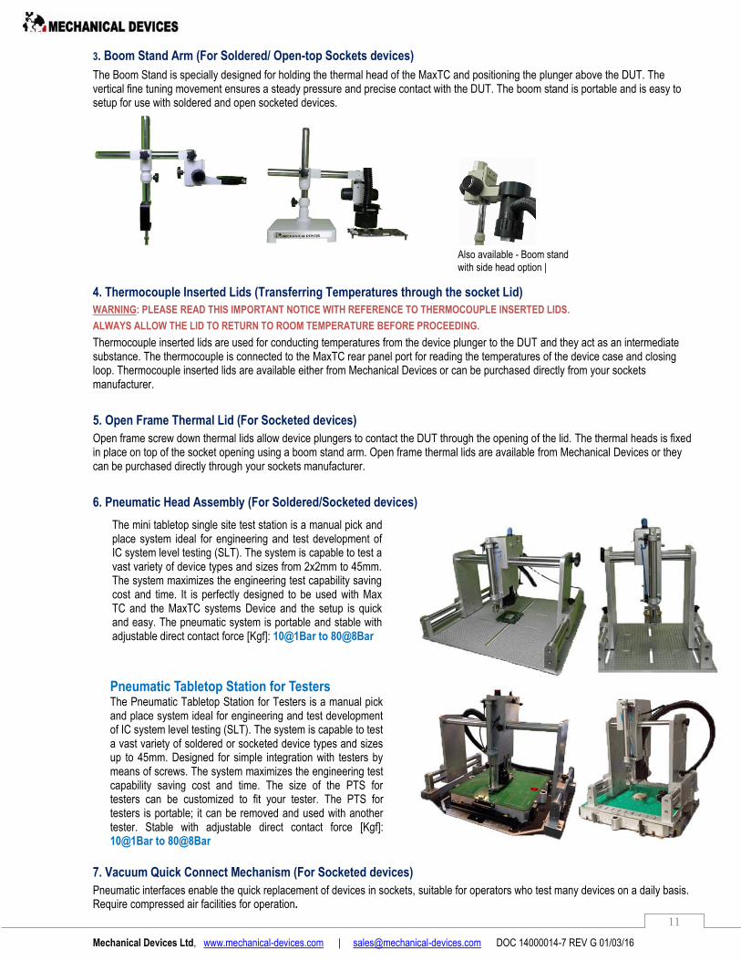
3. Boom Stand Arm (For Soldered/ Open-top Sockets devices)
The Boom Stand is specially designed for holding the thermal head of the MaxTC and positioning the plunger above the DUT. The vertical fine tuning movement ensures a steady pressure and precise contact with the DUT. The boom stand is portable and is easy to setup for use with soldered and open socketed devices.
4. Thermocouple Inserted Lids (Transferring Temperatures through the socket Lid)
WARNING: PLEASE READ THIS IMPORTANT NOTICE WITH REFERENCE TO THERMOCOUPLE INSERTED LIDS.
ALWAYS ALLOW THE LID TO RETURN TO ROOM TEMPERATURE BEFORE PROCEEDING.
Thermocouple inserted lids are used for conducting temperatures from the device plunger to the DUT and they act as an intermediate substance. The thermocouple is connected to the MaxTC rear panel port for reading the temperatures of the device case and closing loop. Thermocouple inserted lids are available either from Mechanical Devices or can be purchased directly from your sockets manufacturer.
5. Open Frame Thermal Lid (For Socketed devices)
Open frame screw down thermal lids allow device plungers to contact the DUT through the opening of the lid. The thermal heads is fixed in place on top of the socket opening using a boom stand arm. Open frame thermal lids are available from Mechanical Devices or they can be purchased directly through your sockets manufacturer.
6. Pneumatic Head Assembly (For Soldered/Socketed devices)
7. Vacuum Quick Connect Mechanism (For Socketed devices)
Pneumatic interfaces enable the quick replacement of devices in sockets, suitable for operators who test many devices on a daily basis. Require compressed air facilities for operation.
The mini tabletop single site test station is a manual pick and place system ideal for engineering and test development of IC system level testing (SLT). The system is capable to test a vast variety of device types and sizes from 2x2mm to 45mm. The system maximizes the engineering test capability saving cost and time. It is perfectly designed to be used with Max TC and the MaxTC systems Device and the setup is quick and easy. The pneumatic system is portable and stable with adjustable direct contact force [Kgf]: 10@1Bar to 80@8Bar
Pneumatic Tabletop Station for Testers The Pneumatic Tabletop Station for Testers is a manual pick and place system ideal for engineering and test development of IC system level testing (SLT). The system is capable to test a vast variety of soldered or socketed device types and sizes up to 45mm. Designed for simple integration with testers by means of screws. The system maximizes the engineering test capability saving cost and time. The size of the PTS for testers can be customized to fit your tester. The PTS for testers is portable; it can be removed and used with another tester. Stable with adjustable direct contact force [Kgf]: 10@1Bar to 80@8Bar
Also available - Boom stand
with side head option |

Mechanical Devices Ltd, www.mechanical-devices.com | [email protected] DOC 14000014-7 REV G 01/03/16
12
For full solution the Vacuum system consists of three components
Quick Connect Vacuum Generation Unit P/N - VGU485
Quick connect P/N QCV485-30
Vacuum Adapter plate P/N – VBA485-30
System Enclosure (mm/inch): 140(L) x140(W)x 63.5 (H) 5.5(L) x 5.5(W) x 2.5(H) Fluid admitted – compressed air (6mm hose) Service pressure range: 87-130 psi (0.6-0.9Mpa) Vacuum level: -26.5 in.Hg (-90 kPa;0.9Bar)
100/140/160mm deep cyclone vacuum pad. Vacuum hose m/(ft): 1.0meter (3.25ft) DUT pressure force: 0-13.9Kg/ Force.
Custom designed to match customer specified test socket/board Peek base with round edge aluminum plate.
The quick Connect Vacuum Mechanism comes in 3 different sizes:
1. D1 – 100mm/up to 4.8Kg 2. D1 – 140mm/up to 9.6Kg 3. D1 – 160mm/up to 13.9Kg

Mechanical Devices Ltd, www.mechanical-devices.com | [email protected] DOC 14000014-7 REV G 01/03/16
13
Specifications
The MaxTC technical specifications are provided in
General
Temperature Range -65⁰C to 175⁰C
Cooling Power 60W@-45⁰C
Temperature Accuracy < 0.5° C
Temperature Stability 0.2⁰C
Typical Transition Rates 25°C to -40°C in < 2 minutes
25°C to 125°C in < 1 minutes
Temperature Sensor Tcase PT100 Thermisor
Thermal-Diode through the Ethernet port
Thermocouple K type Connector
Temperature Calibration Software Calibrated
Remote Interface Ports Ethernet (TCP / IP)
DUT (Device Under Test) Pressure Force 2 - 100 Kg / Force(depending on interface)
DUT Dimensions From 2x2 mm to 100x100mm
DB (Decibels). Rating 45 dBA
MTBF (Mean Time Between Failures) 70,000hr
Mechanical Dimensions
System Enclosure mm / (inch) L 620 (24.4) x W 480 (18.9) x H 360 (14.1)
System Weight 55 Kg
Thermal Head (mm) 80 mm Diameter
Thermal Head Hose 2 meter (6.5ft) standard, 3 meter (10ft) optional
System Requirements
Electrical 208/240 VAC
50/60 Hz, single phase, 16A Max
Ambient Operating Temperature 5°C to 35°C (40 to 95°F)
Ambient Operating Humidity 20% to 95% RH (Relative Humidity)
Compressed Dry Air <0.5cfm (1.2-3.0 PSI
Dew Point >-70⁰C (-100F)
Connection 6mm Industrial Standard Quick Disconnect
Mechanical Devices Ltd, www.mechanical-devices.com | [email protected] DOC 14000014-7 REV G 01/03/16
14
Operation
This chapter provides step-by-step instructions for operating the MaxTC.
Please check the Mechanical Devices YouTube channel for more in depth instructions: http://www.youtube.com/user/MaxTCMd?feature=mhee
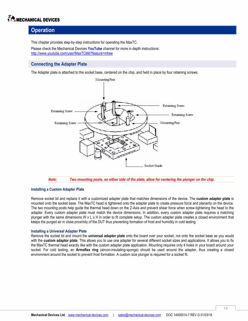
Connecting the Adapter Plate
The Adapter plate is attached to the socket base, centered on the chip, and held in place by four retaining screws.
Note: Two mounting posts, on either side of the plate, allow for centering the plunger on the chip.
Installing a Custom Adapter Plate Remove socket lid and replace it with a customized adapter plate that matches dimensions of the device. The custom adapter plate is mounted onto the socket base. The MaxTC head is tightened onto the adapter plate to create pressure force and planarity on the device. The two mounting posts help guide the thermal head down on the Z-Axis and prevent shear force when screw-tightening the head to the adapter. Every custom adapter plate must match the device dimensions. In addition, every custom adapter plate requires a matching plunger with the same dimensions W x L x H in order to fit complete setup. The custom adapter plate creates a closed environment that keeps the purged air in close proximity of the DUT thus preventing formation of frost and humidity in cold testing. Installing a Universal Adapter Plate Remove the socket lid and mount the universal adapter plate onto the board over your socket, not onto the socket base as you would with the custom adaptor plate. This allows you to use one adapter for several different socket sizes and applications. It allows you to fix the MaxTC thermal head exactly like with the custom adapter plate application. Mounting requires only 4 holes in your board around your socket. For cold testing, an Armaflex ring (aircon-insulating-sponge) should be used around the adapter, thus creating a closed environment around the socket to prevent frost formation. A custom size plunger is required for a socket fit.
Mechanical Devices Ltd, www.mechanical-devices.com | [email protected] DOC 14000014-7 REV G 01/03/16
15
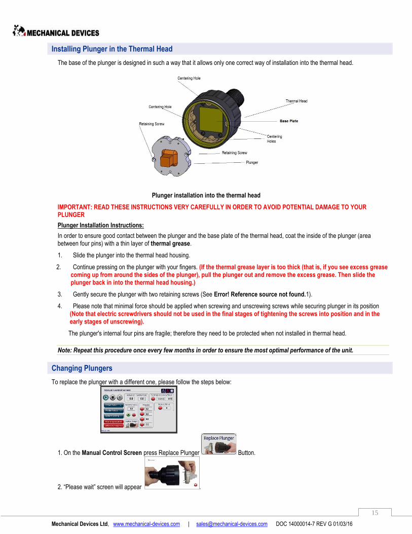
Installing Plunger in the Thermal Head
The base of the plunger is designed in such a way that it allows only one correct way of installation into the thermal head.
Plunger installation into the thermal head
IMPORTANT: READ THESE INSTRUCTIONS VERY CAREFULLY IN ORDER TO AVOID POTENTIAL DAMAGE TO YOUR PLUNGER
Plunger Installation Instructions:
In order to ensure good contact between the plunger and the base plate of the thermal head, coat the inside of the plunger (area between four pins) with a thin layer of thermal grease.
1. Slide the plunger into the thermal head housing.
2. Continue pressing on the plunger with your fingers. (If the thermal grease layer is too thick (that is, if you see excess grease coming up from around the sides of the plunger), pull the plunger out and remove the excess grease. Then slide the plunger back in into the thermal head housing.)
3. Gently secure the plunger with two retaining screws (See Error! Reference source not found.1).
4. Please note that minimal force should be applied when screwing and unscrewing screws while securing plunger in its position (Note that electric screwdrivers should not be used in the final stages of tightening the screws into position and in the early stages of unscrewing).
The plunger's internal four pins are fragile; therefore they need to be protected when not installed in thermal head.
Note: Repeat this procedure once every few months in order to ensure the most optimal performance of the unit.
Changing Plungers
To replace the plunger with a different one, please follow the steps below:
1. On the Manual Control Screen press Replace Plunger Button.
2. “Please wait” screen will appear .

Mechanical Devices Ltd, www.mechanical-devices.com | [email protected] DOC 14000014-7 REV G 01/03/16
16
3. Please wait until “Please remove plunger” message will appear on screen. 4. Now you can remove the plunger and insert a different one into the head.
5. If you would like to cancel replacing the plunger procedure at any point, press Cancel button and follow further instructions on screen.
6. To continue working with the system press in the Continue screen. 7. Please wait until the “Warming up” screen will disappear and you are back in the Manual Control Screen.
Setting Plunger Parameters
Plungers come in different sizes and shapes, and they are made of different materials, such as Copper or Aluminum. These differences in plungers have direct impact on the offset values of the system.
1. For best performance of the plunger please follow these steps and fill in the unique plunger parameters for each plunger.
2. In Manual Control Screen press , located at the bottom bar.
3. You will be taken to the System Setting Screen. On the right side you will see Plunger Parameters box.
Fill in the Proportional, Integral, Derivative (P I D) values found on the label of the original plunger box.
4. Return back to Manual Control Screen by pressing Home button .
Auto Tune Procedure
When P I D values of the plunger are not available, you can use Auto Tune Procedure and let the MaxTC system automatically detect plunger’s P I D values. 1. Using the same method as shown above for Installing Plunger in Thermal Head, insert your plunger into the thermal head.

Mechanical Devices Ltd, www.mechanical-devices.com | [email protected] DOC 14000014-7 REV G 01/03/16
17
2. On the Manual Control Screen select Set Point box and set the temperature to 60.0 (C) then proceed to System Setting.
3. In System Setting screen on the right of this screen you will see the Plunger Parameters box.
Select red Auto Tune button located on the bottom of the box.
4. A dialog box “Are you sure you want to do this operation?” will appear. Press the Yes button.
5. The Auto Tune button will become green. Plunger Parameters box values will reset based on the plunger type and size.
6. You can return to Manual Control Screen by pressing the corresponding button.
Installing the Thermal Head on the Adapter Plate
Installing the Thermal Head on the Adapter
To install the thermal head on the adapter:
1. Place the thermal head over the adapter and align the centering holes with the mounting posts
Note – Quick connect vacuum adapter plates do not have alignment pins.
2. Press down on the adapter plate and turn the thermal head clockwise thereby screwing it to the adapter.
Mechanical Devices Ltd, www.mechanical-devices.com | [email protected] DOC 14000014-7 REV G 01/03/16
18
Activating the MaxTC
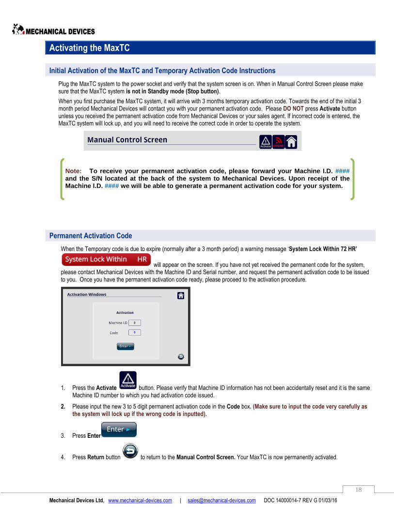
Initial Activation of the MaxTC and Temporary Activation Code Instructions
Plug the MaxTC system to the power socket and verify that the system screen is on. When in Manual Control Screen please make sure that the MaxTC system is not in Standby mode (Stop button).
When you first purchase the MaxTC system, it will arrive with 3 months temporary activation code. Towards the end of the initial 3 month period Mechanical Devices will contact you with your permanent activation code. Please DO NOT press Activate button unless you received the permanent activation code from Mechanical Devices or your sales agent. If incorrect code is entered, the MaxTC system will lock up, and you will need to receive the correct code in order to operate the system.
Permanent Activation Code
When the Temporary code is due to expire (normally after a 3 month period) a warning message ‘System Lock Within 72 HR’
will appear on the screen. If you have not yet received the permanent code for the system, please contact Mechanical Devices with the Machine ID and Serial number, and request the permanent activation code to be issued to you. Once you have the permanent activation code ready, please proceed to the activation procedure.
1. Press the Activate button. Please verify that Machine ID information has not been accidentally reset and it is the same Machine ID number to which you had activation code issued.
2. Please input the new 3 to 5 digit permanent activation code in the Code box. (Make sure to input the code very carefully as the system will lock up if the wrong code is inputted).
3. Press Enter
4. Press Return button to return to the Manual Control Screen. Your MaxTC is now permanently activated.
Note: To receive your permanent activation code, please forward your Machine I.D. #### and the S/N located at the back of the system to Mechanical Devices. Upon receipt of the Machine I.D. #### we will be able to generate a permanent activation code for your system.

Mechanical Devices Ltd, www.mechanical-devices.com | [email protected] DOC 14000014-7 REV G 01/03/16
19
Warranty / Calibration Codes
When you first purchase the MaxTC system, it will come with one year warranty and calibration. At the end of the first year Warranty Valid / Calibration Valid buttons will change to red Warranty expired / Calibration expired buttons. Do not worry, the system continues to be fully operational. The red buttons are only a reminder that the system in no longer covered by manufacturer’s warranty and that the last calibration was done over a year ago. If you decide to purchase additional warranty coverage, or to do a system calibration, please contact Mechanical Devices or your sales agent and request a quote.
If for any reason you need to reenter valid Warranty and Calibration code, you can obtain it from Mechanical Devices by submitting Machine ID and serial number of the system. Please make sure the Machine ID hasn’t changed from the number you submitted to Mechanical Devices. Warranty code and Calibration code is a multi-digit code, therefore pay attention when entering the values.
After entering the new Warranty / Calibration codes the Warranty valid / Calibration valid buttons will turn back to green.

Mechanical Devices Ltd, www.mechanical-devices.com | [email protected] DOC 14000014-7 REV G 01/03/16
20
Setting Temperature
Setting Temperature
Press , the Manual Control Screen is displayed. This screen is used for setting temperatures.
Set Point Temperature
To set a Set Point temperature:
1. Press the Set Point [C] field: . The Number Keypad is displayed.
2. Enter the desired temperature by pressing the number keys, followed by pressing Enter.
Note that the measured temperature at any given time is displayed in the field.
3. The Setting: Accuracy/Soak is a settling time function which allows you to define a function in two variables, soak and accuracy. Enter both values. When the accuracy [C] value is met the soak clock [S] will start ticking. When the clock reaches its value the red light will turn green indicating that the soak time is completed at the set point and testing can be started. When using remote control operation a bit will be raised to your tester indicating that the two variables have been met at Set Point temperature, and the tester will start testing.
4. The Rate [C/Min] controls the rate of °C/Min. When the indicator button is red it means that the system is operates at its maximum performance and it can even reach 70°C/min rate. When the indicator button is green the operator has the option to change the rate from 1°C/min to 50°C/min. Note - If the Rate is set to 0⁰C the system will not function.
Mechanical Devices Ltd, www.mechanical-devices.com | [email protected] DOC 14000014-7 REV G 01/03/16
21
Setting Incremental Rates
Setting Incremental [C] means setting *Marginal/Additional rates. You use this option to set the MaxTC to achieve the Set Point temperature in stages.
In the Incremental[C] field; set the increment value in the box. Then either by pressing or you can increase the set point by the increment or decrease temperatures respectively.
Set the maximum temperature in the Max Temp field via the Number Keypad. This prevents the MaxTC from over-shooting the maximum defined temperature. Note – be aware user cannot input a higher value in the set point box than what is defined as the max temperature in the Max temperature box.
Setting Presets
You can use the Presets panel to enter preset temperatures. You can set up to four preset temperatures.
To set up a Preset:
1. Press the field into which you want to set the preset. The Number Keypad will get displayed.
2. Set the desired temperature, press Enter. The temperature is now displayed in the temperature field.
To activate a preset temperature, press the red button associated with the desired preset, for example . Once the button turns green the temperature is displayed in the set point box.
Setting Thermocouple [K-Type]
The system acts like a thermometer and reads the temperature of the thermocouple. Insert the thermocouple cable in to the K-Type socket located on the rear panel of the MaxTC. Automatically on the Manual Control Screen a Thermocouple [C] window will
appear
Mechanical Devices Ltd, www.mechanical-devices.com | [email protected] DOC 14000014-7 REV G 01/03/16
22
Setting a Ramp/Soak Sequence
The Ramp/Soak panel enables you to preset a number of temperature points that are to be actuated for specified times.
A Ramp/Soak sequence looks like this:
1. From the Manual Control Screen press the Profile Setup: button. The Ramp/Soak screen will get displayed:
2. Press the first Set.P: field and enter the value using the Number Keypad.
3. Press the associated Rate: field and enter the desired rate, C/Min. This is the Rate at which the temperatures to reach the Set.P setting.
4. Press the associated Soak: field and enter the desired time (in minutes) that temperature of the Set.P temperature setting is to be kept.
5. Repeat steps 2, 3 and 4 for each point in the Ramp/Soak sequence.
6. To activate a Ramp/Soak sequence, press the Profile: button in the Ramp/Soak panel. Note that the button turns
blue , indicating that the sequence has started.
7. Use the settling time function to define a function in two variables, soak and accuracy for every step in the sequence. When the accuracy value is met and the clock reaches its value the red light will turn green indicating that the sequence step soak/clock started.
Mechanical Devices Ltd, www.mechanical-devices.com | [email protected] DOC 14000014-7 REV G 01/03/16
23
8. When the user has programed the sequence it is highly advisable to finish the routine with +25°C as the plunger will remain at the last sequence step temperature after the sequence has completed.
*IMPORTANT: PLEASE NOTE THE ABOVE SENTENCE IS FOR YOUR PERSONAL PROTECTION FROM HOT/COLD HAZARDS.
9. For programing a partial sequence (less than 10 steps) please set the last columns to zeros
10. To have a program that goes one way use and to set a continuous program use .
11. Press Return to return to the Manual Control Screen. Note that in the Manual Control Screen the Profile is now shown to be active:
Using the Offset Table
The Offset Table is used to offset the TJ (Temperature Junction) and to adapt the Tcase to control using the temperature offset.
To use the offset table press the Offset Table button located on the left hand side of the Manual Control Screen.
This setting is used to offset the plunger temperature and to control the junction temperature (TJ) most commonly if the DUT is a soldered device (it also works for socketed devices as well.). The user can program up to 3 temperature look-up tables which will show an empirical TJ value and offset the Tplunger (Tcase) reading accordingly.
In the Offset Window screen will you will see three panels:
1. Manual Offset Table
2. Current Temperature
3. Automated Feedback

Mechanical Devices Ltd, www.mechanical-devices.com | [email protected] DOC 14000014-7 REV G 01/03/16
24
- Plunger Temperature Monitoring
- Junction Temperature Monitoring
- Temperature Set Point Entery (Keyboard)
- Junction Temperature feedback indicator
- Temperature set point indicator
Please note that when TJ feedback or set point is activated (Pin 4 or 3 set to 24V) above indicators will be green.
In Manual Offset Table you have the possibility to program up to 3 profile parameters which is a time saving and convenient way to test your DUT’s junction temperature. Press Profile 1 to set up your first look-up table. Just apply the offset temp on the TJ column, for that you need to measure the junction temperature and put the value in the right T Junction temperature.
For example start with TJ #14 and input the offset junction temp reading value can be +140C, according to the DUT junction reading). Continue setting the TJ for all fields until you reach the lowest temperature desired. (Note that you do not have to use the entire table, you may only need to test the TJ from part of the table rather than #14 to #1).
Once you have programmed in your values on the table press the button to activate the profile and this button
will appear. You are now clear to continue with your testing, or to program up to 2 more cycles in the remaining Profile’s.
The Reset Profile Parameters button is used to reset the offset values If you reset the profile you change all the TJ values to the default meaning no offset.
If you select the Automated Feedback Panel You will need to use D-Type connector
Mechanical Devices Ltd, www.mechanical-devices.com | [email protected] DOC 14000014-7 REV G 01/03/16
25
Using a Remote Computer
Mechanical Devices supplies a software interface Hyper Terminal which allows you to connect to the MaxTC remotely using your PC. You using this software you are able to enter certain commands using an ASCII format in order to control and monitor the MaxTC temperatures. You can download Hyper Terminal and other remote connection data files including drivers for C++, Visual Basic, Executable Driver, ASCII test command, Labview, and Java from our website at: http://www.mechanical-devices.com/homesites/PageGen2.asp?page=36490
Setting up Remote Connection
To setup a remote connection:
1. In Manual Control Screen Press system settings
2. Press Set IP
3. The following screen is displayed:
4. Press the input fields for IP to enter the IP address.
5. Press the input fields for SUB to enter the Subnet mask.
6. Press the input fields for GAT to enter the Default Gateway.
Mechanical Devices Ltd, www.mechanical-devices.com | [email protected] DOC 14000014-7 REV G 01/03/16
26
7. Press Home ( ) to return to the Manual Control Screen.
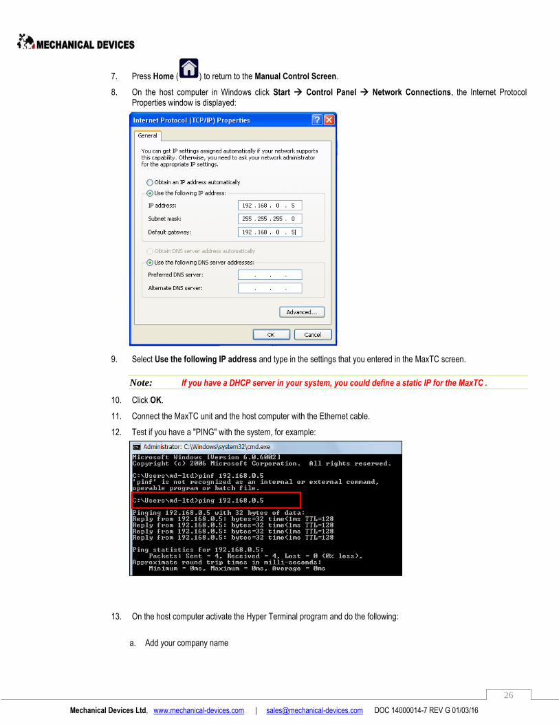
8. On the host computer in Windows click Start Control Panel Network Connections, the Internet Protocol Properties window is displayed:
9. Select Use the following IP address and type in the settings that you entered in the MaxTC screen.
Note: If you have a DHCP server in your system, you could define a static IP for the MaxTC .
10. Click OK.
11. Connect the MaxTC unit and the host computer with the Ethernet cable.
12. Test if you have a "PING" with the system, for example:
13. On the host computer activate the Hyper Terminal program and do the following:
a. Add your company name

Mechanical Devices Ltd, www.mechanical-devices.com | [email protected] DOC 14000014-7 REV G 01/03/16
27
b. Use port 5000 and TCP/IP communication.
c. Go to Properties Settings ASCII Setup and select all the checkboxes for ASCII Receiving:
d. Click OK

Mechanical Devices Ltd, www.mechanical-devices.com | [email protected] DOC 14000014-7 REV G 01/03/16
28
Entering Commands in Hyper Terminal
You enter commands by “paste to host” directly into the Hyper Terminal main screen, for example:
The formats of the commands are:
Read command form MI (register cell): mMIXXXX?
Where XXXX is the MI register address.
Example: Sending the following command: mMI0669? The response is MI0669,1234, which means the controller has a value of 1234 in MI669.
Write command for MI (register cell): mMIXXXX,YYYY
Where XXXX is the MI register address, and YYYY is the register new value.
Example: Sending the following command: mMI0669,4321. The response is OK, which means the controller now has a value of 4321 in MI669.
Read command for MB: mMBXXXX?
Where XXXX is the MB bit cell address.
Example: Sending the following command: mMB0001? The response is MI0001,1, which means that the controller has a value of 1 in MB001.
Write command for MB: mMBXXXX,Y
Where XXXX is the MB Bit cell address, and Y is the bit cell new value.
Example: Sending the following command: mMB0001,1. The response is OK, which means the controller has value of 1 in MB1.
Other examples are:
MI 699 - Change/Read the Set Point temperature. Example: MI699=455 meaning 45.5[C]
MI 6 - Read the current thermal head temperature. Example: MI6=900 meaning 90.0[C]
MB 20 – A value of 1 sets the system in the standby (Paused) mode, a value of 0 activates the system
Mechanical Devices Ltd, www.mechanical-devices.com | [email protected] DOC 14000014-7 REV G 01/03/16
29
Register Maps
Manual Control Screen Register Map
BIT Description
1 MB 20 Standby / play
2 MI 6 Actual temp [C]
3 MI 699 Set point [C]
4 MB 83 Converge bit - Soak time reached within accuracy [C/s] [read only bit]
5 MI 65 Temperature accuracy [C]
6 MI 313 Soak time accuracy [s]
7 MB 74 Activate rate [C/min]
8 MI 45 Rate [C/min] value
9 MB 23 Activate Preset 1
10 MI 695 Preset 1 temp value
11 MB 24 Activate Preset 2
12 MI 696 Preset 2 temp value
13 MB 76 Activate Preset 3
14 MI 697 Preset 3 temp value
15 MB 26 Activate Preset 4
16 MI 698 Preset 4 temp value
17 MI 69 Incremental [C] - Step
18 MB 85 / 86 Incremental + / -
19 MB 327 Pause system
20 MI 218 Thermocouple Temperature [C]
21 MI 1 T Plunger [C]
22 MB 157 Thermocouple Indicator
23 MB 66 Initiate Replace Plunger sequence, change from 0 to 1 MB 326 Auto trigger for plunger disassembly, changes automatically from 0 to 1 MB 999 System reset after new plunger install, change from 0 to 1 MB 321 End of Replace Plunger sequence, change from 0 to 1
MB 86 MB 85

Mechanical Devices Ltd, www.mechanical-devices.com | [email protected] DOC 14000014-7 REV G 01/03/16
30
Offset Window Register Map
BIT Description
1 MB 162 Profile 1– Activate
2 MB 163 Profile 2 – Activate
3 MB 164 Profile 3 – Activate
4 MB 161 Reset Profile Parameters button
5 MB 294 Indication bit for warm up mode (“1” warm up on, “0” warm up finished)
6 MI 139/141/140/142/143/144/145 T Plunger
7 MI 165/162/161/160/159/158/157 T Offset
8 MI 146/147/148/149/150/151/152 T Plunger
9 MI 156/155/154/153/132/133/163 T Offset
10 MI 1 Current Temperature - T Plunger
11 MI 11 Current Temperature - T J
12 MI 699 Current Temperature – Set Point
13 MB 171 T J Feedback
14 MB 172 Set Point Feedback
MB162

Mechanical Devices Ltd, www.mechanical-devices.com | [email protected] DOC 14000014-7 REV G 01/03/16
31
Profile Screen Register Map
BIT Description
1 MB 27 Profile 1 - Activate
2 MB 130 Profile 2 - Activate
3 MB 131 Profile 3 - Activate
4 MB 132 One arrow: One cycle Two arrows: Repetitive profile
5 MB 107/108/109/110/112/113/114/125/128/129 Profile step indication
6 MI 751/752/753/754/755/756/757/758/759/760 Set Point [C]
7 MI 761/762/763/764/765/766/767/768/769/770 Rate [C/min]
8 MI 771/772/773/774/775/776/777/778/779/780 Soak [min]
9 MI 6 Actual [C]
10 MI 699 Set Point [C]
11 MB 83 Soak Time Reached
12 MI 65 Settling: Accuracy/Soak ---- +/- Temperature [C]
13 MI 313 Settling: Accuracy/Soak ---- [s]
MI 6 MI 699
Mechanical Devices Ltd, www.mechanical-devices.com | [email protected] DOC 14000014-7 REV G 01/03/16
32
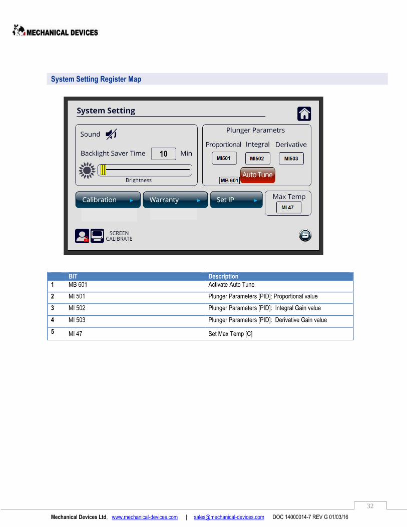
System Setting Register Map
BIT Description
1 MB 601 Activate Auto Tune
2 MI 501 Plunger Parameters [PID]: Proportional value
3 MI 502 Plunger Parameters [PID]: Integral Gain value
4 MI 503 Plunger Parameters [PID]: Derivative Gain value
5 MI 47 Set Max Temp [C]
Mechanical Devices Ltd, www.mechanical-devices.com | [email protected] DOC 14000014-7 REV G 01/03/16
33
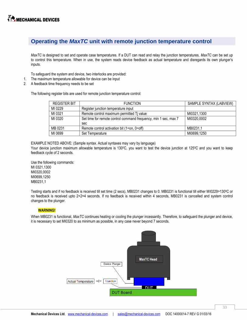
Operating the MaxTC unit with remote junction temperature control
MaxTC is designed to set and operate case temperatures. If a DUT can read and relay the junction temperatures, MaxTC can be set up to control this temperature. When in use, the system reads device feedback as actual temperature and disregards its own plunger’s inputs.
To safeguard the system and device, two interlocks are provided:
1. The maximum temperature allowable for device can be input
2. A feedback time frequency needs to be set
The following register bits are used for remote junction temperature control:
REGISTER BIT FUNCTION SAMPLE SYNTAX (LABVIEW)
MI 0229 Register junction temperature input
MI 0321 Remote control maximum permitted Tj value MI0321,1300
MI 0320 Set time for remote control command frequency, min 1 sec, max 7 sec
MI0320,0002
MB 0231 Remote control activation bit (1=on, 0=off) MB0231,1
MI 0699 Set Temperature MI0699,1250
EXAMPLE NOTED ABOVE: (Sample syntax. Actual syntaxes may vary by language)
Your device junction maximum allowable temperature is 1300C, you want to test the device junction at 1250C and you want to keep feedback cycle of 2 seconds.
Use the following commands:
MI 0321,1300
MI0320,0002
MI0699,1250
MB0231,1
Testing starts and if no feedback is received till set time (2 secs), MB0231 changes to 0. MB0231 is functional till either MI0229>1300C or no feedback is received upto 2+2=4 seconds. If no feedback is received within 4 seconds, MB0231 is cancelled and system control changes to the plunger.
WARNING!
When MB0231 is functional, MaxTC continues heating or cooling the plunger incessantly. Therefore, to safeguard the plunger and device, it is necessary to set MI0320 to as minimum as possible, in any case never beyond 7 seconds.
Mechanical Devices Ltd, www.mechanical-devices.com | [email protected] DOC 14000014-7 REV G 01/03/16
34
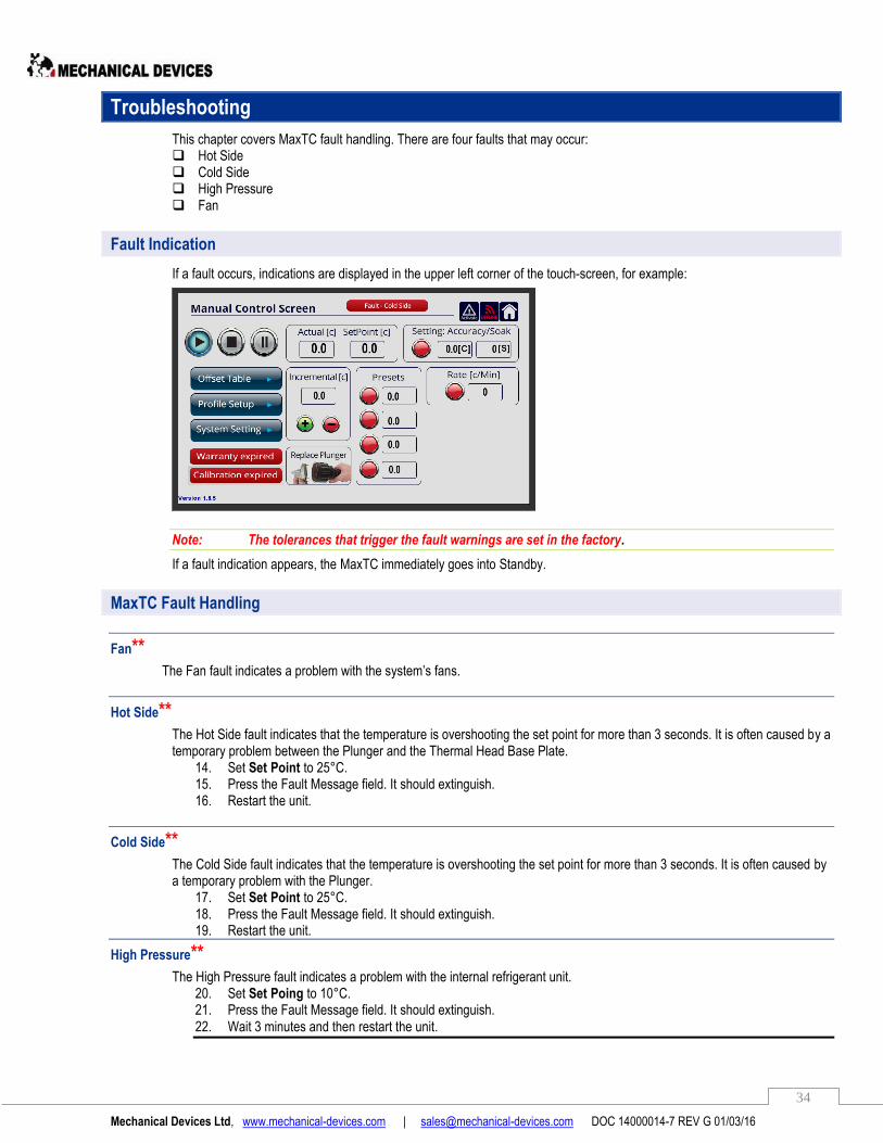
Troubleshooting
This chapter covers MaxTC fault handling. There are four faults that may occur: Hot Side Cold Side High Pressure Fan
Fault Indication
If a fault occurs, indications are displayed in the upper left corner of the touch-screen, for example:
Note: The tolerances that trigger the fault warnings are set in the factory.
If a fault indication appears, the MaxTC immediately goes into Standby.
MaxTC Fault Handling
Fan** The Fan fault indicates a problem with the system’s fans.
Hot Side** The Hot Side fault indicates that the temperature is overshooting the set point for more than 3 seconds. It is often caused by a temporary problem between the Plunger and the Thermal Head Base Plate.
14. Set Set Point to 25°C. 15. Press the Fault Message field. It should extinguish. 16. Restart the unit.
Cold Side** The Cold Side fault indicates that the temperature is overshooting the set point for more than 3 seconds. It is often caused by a temporary problem with the Plunger.
17. Set Set Point to 25°C. 18. Press the Fault Message field. It should extinguish. 19. Restart the unit.
High Pressure**
The High Pressure fault indicates a problem with the internal refrigerant unit. 20. Set Set Poing to 10°C. 21. Press the Fault Message field. It should extinguish. 22. Wait 3 minutes and then restart the unit.

Mechanical Devices Ltd, www.mechanical-devices.com | [email protected] DOC 14000014-7 REV G 01/03/16
35
Plunger Troubleshooting
When the MaxTC’s Actual temperature does not reach the Set Point temperature, please perform the following tests. Note: As you go through the procedure, be ready to take screenshots of the plunger and the MaxTC as per instructions.
1st scenario
1. In the Manual Control Screen, if the Actual box displays **** it is an indication the plunger is malfunctioning.
2. Carefully remove the plunger from the thermal head of the MaxTC.
3. Insert a different plunger (if available) into the thermal head.
4. Place the faulty Plunger at a safe warm dry place, for about 24 hours, until the humid effect has worn off.
5. Take a photo of the faulty/non-functioning plunger. Make sure you’re looking at the plunger from above and the engraving
of the serial number is fully visible:
6. After 24hrs please reinsert the "faulty plunger" once again into the MaxTC thermal head and see how it functions.
7. If the plunger continues to malfunction, please contact Mechanical devices support at [email protected]
2nd scenario When system is not heating or cooling, please do the following test.
1. In Manual Control Screen set Set Point temperature to 80C.
2. In Settling: Accuracy/Soak box enter 0.5C in the first box and 30s in the second box.
3. Wait until the system settles and Accuracy/Soak indicator turns green .
4. Take a screenshot of the Manual Control Screen.
5. Enter -40C in Set Point box.
Serial Number engraving

Mechanical Devices Ltd, www.mechanical-devices.com | [email protected] DOC 14000014-7 REV G 01/03/16
36
6. Wait until the system settles and Accuracy/Soak indicator turns green .
7. Take a screenshot of the Manual Control Screen.
8. Enter 25C in the Set Point box.
9. Carefully remove the plunger from the thermal head of the MaxTC.
10. Take a photo of the faulty/non-functioning plunger. Make sure you’re looking at the plunger from above and the engraved serial
number is fully visible.
11. Insert a different plunger (if available) into the thermal head.
12. Send all photos to Mechanical Devices support team at [email protected]
Communication Problems with MaxTC
If you do not have good connection between the MaxTC and the Ethernet network we recommend that you connect the MaxTC directly
to your computer. The direct communication is intended to eliminate the possibility of server block communication.
1 In the MANUAL CONTROL SCREENL press the system setting button
2 Press Set IP
3 Enter the following values
And Press to return to the Manual Control Screen.
4 On the host computer in Windows click
Start Control Panel Network and sharing center Ethernet
5 The "Ethernet Status" window is displayed
Press properties
6 The Internet Protocol Properties window is displayed
Select: "Internet Protocol Version 4 (TCP/IPv4)
And press properties

Mechanical Devices Ltd, www.mechanical-devices.com | [email protected] DOC 14000014-7 REV G 01/03/16
37
7 Internet Protocol Version 4 Properties is displayed
Select "use the following IP address"
Fill the following values and press ok
8 Exit from all the windows
And Connect the Ethernet cable between the rear MaxTC panel unit and the host computer
9 Go to the run window.
Type the CMD command in the run window and press ok
10 CMD window is display
11 In the CMD window type: ping 10.100.102.17 As shown in the MaxTC and Press Enter
12 If connection is ok the following screen will be displayed

Mechanical Devices Ltd, www.mechanical-devices.com | [email protected] DOC 14000014-7 REV G 01/03/16
38
13 If there is no connection the following screen is displayed:
Then check Ethernet connection and repeat the procedure

Mechanical Devices Ltd, www.mechanical-devices.com | [email protected] DOC 14000014-7 REV G 01/03/16
39
MaxTC Technology
System Overview
The MaxTC Thermal Head contains the Plunger that transmits the temperature to the DUT. The Plunger, when the Thermal Head interfaces on the DUT, is in direct contact with the chip being tested. In this way temperature is passed by direct conduction between the Plunger and the chip. The Plunger contains a thermal sensor (PT100) which makes 30 measurements per second. The sensor data is passed to the system which, in turn, makes 30 thermal corrections within a second, Actively Heating and cooling the plunger to guarantee the ±0.2°C accuracy on the DUT. The Thermal Head also has four purge nozzles for the introduction of nitrogen or dry air to the testing area, access line is connected to the unit’s back panel. The constant nitrogen or dry air flow creates a frost and humidity free shield around the DUT. For additional Maxibility the system can be controlled remotely through the ethernet communication port.
Benefits of Fluid-Free Operation
MaxTC is Fluid Free – the system does not contain any fluids and it does not require external chillers for its operation. MaxTC is a self-contained standalone system that completely eliminates the need for chillers. Chiller-based systems always run the risk of fluid leaks that can cause severely damage to the tester. MaxTC in that it is fluid free means that the thermal heads operate safely on tester heads without risks of spills or leaks.
Facilities Free Operation
MaxTC is self-contained and does not require compressed air or chillers for its operation. The MaxTC is a standalone system that requires only a 15A wall outlet and purge. The unit can be operated regardless of the availability of a compressed air line and thanks to its ultra-quiet operation (45Dba) can be also operated on an office desk. By acquiring MaxTC systems, newly opened laboratories can save start-up, electricity & maintenance high costs that are associated with ownership of compressed air and chiller facilities.
Cooling Power
The MaxTC cooling power is a function of the Device Plunger selection and of the temperature transfer coefficient (here in after referred to as the "H factor") between the touching surfaces as shown in the power dissipation formula:
The higher the H factor is, the more powerful a thermal system can be, MaxTC systems H factor is very high, 4000(W·K¯¹·m¯² ) compared to the H factor of an air-stream-based systems which is only 120 (W·K¯¹·m¯²). As a consequence of which MaxTC systems can effectively cool high power device while air-stream-based systems cannot.
Qwatt = H x Asurface (Tcase – Tambient) Q (watt) = The amount of dissipation, in watts, that a thermal system can dissipate. H (W·K¯¹·m¯² )= Temperature transfer coefficient. A (m²) = the surface area of the device Tcase (°K) = the temperature of the device Tambient (°K) = the temperature of the device plunger
Thermal Loads
Thermal load is the entire wattage of which a thermal application consists. Thermal loads of DUT´s are a function of: A. the application (socket or soldered). B. the DUT´s thermal dissipation and dimensions. C. the board´s dimensions and components wattage. D. the purge flow rate. Mechanical-Devices have developed a thermal analysis software that precisely calculates thermal loads on the DUT case. By knowing the actual thermal load Mechanical-Devices can guarantee Tcase temperatures
Mechanical Devices Ltd, www.mechanical-devices.com | [email protected] DOC 14000014-7 REV G 01/03/16
40
Settling Time
MaxTC direct conduction thermal transfer solution is characterized by very short Tcase settling time. Temperatures transfer speed is a function of the temperature transfer coefficient (here in after referred as the "H factor") between the touching surfaces - the higher the H factor is, the faster temperatures will transfer between substances. MaxTC systems H factor is very high 4000(W·K¯¹·m¯²) compared to air- stream-based systems H factor which is only 120(W·K¯¹·m¯²) as a consequence temperatures are transferred within seconded from the device plunger to the DUT, dropping the case settling time to seconds. Example - Jumping into a swimming pool at 10°C will feel cold in a split of a second due to the high temperature transfer coefficient of water to skin (Hwater=3000 )which transferred the 10°C to the skin in a split of a second. However, going outdoors @ 10°C will not feel cold due to the low temperature transfer coefficient of air-skin (Hair=80) which will only transfers the 10°C to the skin after long duration.
MaxTC is ideal for handler´s integration in many ways
1. The unit footprint is very compact and it will not occupy expensive test production floor the MaxTC can be placed inside the handler cabinet or mounted on a shelf.
2. Due to its fluid free operation, the MaxTC does not pose risks of leaks that are associated with chiller-based systems which would severely damage expensive test and handling equipment.
3. MaxTC tri-temp-handler prices are cost effective
MaxTC Ready Sockets Lids
Mechanical-Devices will provide socket manufacturers, free of charge, all the technical information required to manufacture MaxTC Ready Sockets Lids. Acquiring MaxTC ready sockets lids eliminates the need to purchase the mechanical Interface from Mechanical-Devices.
Mechanical Devices sockets support
Since the introduction of the MaxTC on the market, we have custom-designed and manufactured mechanical interfaces that enable MaxTC to operate with test sockets from over 30 different manufacturers worldwide, including: Johnstech, Ironwood, ECT Multitest, YAMAICHI, Enplas, ,Winway Technologies, Paricon, 3M, Wells-CTI, Ardent Concepts, IDI Antares, Phoenix ,Robson RTI, Gold Technologies, Aries Electronics, Plastronics and more. Mechanical-Devices engineering group will design and manufacture mechanical interfaces for every existing socket on the market -from all brands.

Mechanical Devices Ltd, www.mechanical-devices.com | [email protected] DOC 14000014-7 REV G 01/03/16
41
Humidity and Frost Free Operation
MaxTC ensures frost and humidity free test environments through several prevention techniques.
A. Test Site Frost Prevention The MaxTC thermal head has four purge outlets for the introduction of dry air or nitrogen close to the testing area, the constant Nitrogen or Dry Air flow creates a frost and humidity free shield around the DUT. An access line is connected to the unit back panel and the flow goes through the unit and the hose up to the outlets. the flow is software controlled via a solenoid which, by default, automatically opens the purge when the plunger temperature cools to 16°C downwards.
Installing Pressure Regulator and Purge Access Tube The recommended dry air pressure to be used for purge is 0.2 bar. A low amount of dry air (0.2 bar) is sufficient in order to prevent condensation and ice formation on your DUT in low temperatures. In case of too much dry air purge used, it will have a negative side-effect of heating up your DUT environment, and it may become impossible to stabilize at low temperatures required for your testing. In order to apply correct dry air pressure, please use the pressure regulator and purge access tube that was included in the shipment of your thermal testing system. Please refer to the instructions below of how to install pressure regulator and access line (0.6 mm tube) in order to prepare your thermal testing unit for operation with dry air purge.
Step 1. Cut a small segment of around 20 cm in length from a black plastic tube with 0.6mm diameter. Insert one end of the short tube segment into a pipe connector of the pressure regulator.
Step 2. Insert the other end of the short tube segment into the purge inlet located at the back of the thermal testing system.
Purge outlets
Purge outlets
Back panel purge inlet
Front Panel Purge outlet
Mechanical Devices Ltd, www.mechanical-devices.com | [email protected] DOC 14000014-7 REV G 01/03/16
42
Step 3. Insert one end of the long segment of the black tube into the other pipe connector of the pressure regulator.
Step 4. Insert the other end of the long tube segment into the valve connector or regular connector of the dry air gas balloon. Follow manufacturer instructions for connecting to the dry air balloon.
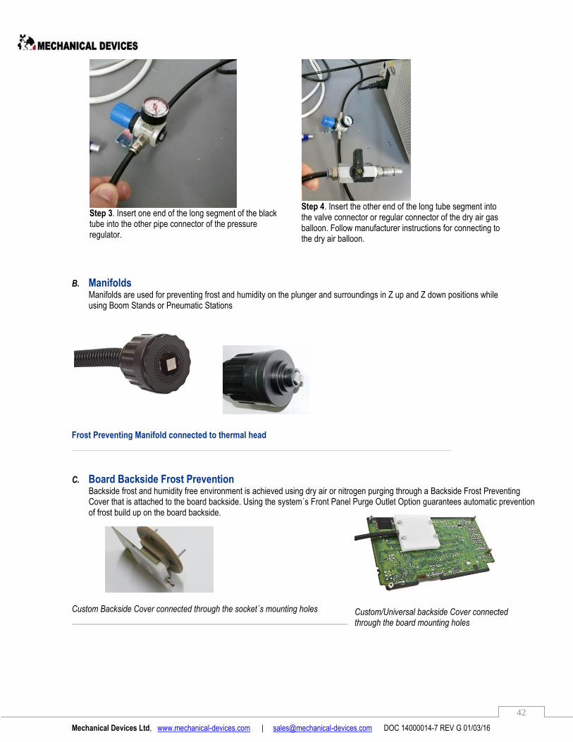
B. Manifolds Manifolds are used for preventing frost and humidity on the plunger and surroundings in Z up and Z down positions while using Boom Stands or Pneumatic Stations
Frost Preventing Manifold connected to thermal head
C. Board Backside Frost Prevention Backside frost and humidity free environment is achieved using dry air or nitrogen purging through a Backside Frost Preventing Cover that is attached to the board backside. Using the system´s Front Panel Purge Outlet Option guarantees automatic prevention of frost build up on the board backside.
Custom Backside Cover connected through the socket´s mounting holes
Custom/Universal backside Cover connected through the board mounting holes
Mechanical Devices Ltd, www.mechanical-devices.com | [email protected] DOC 14000014-7 REV G 01/03/16
43
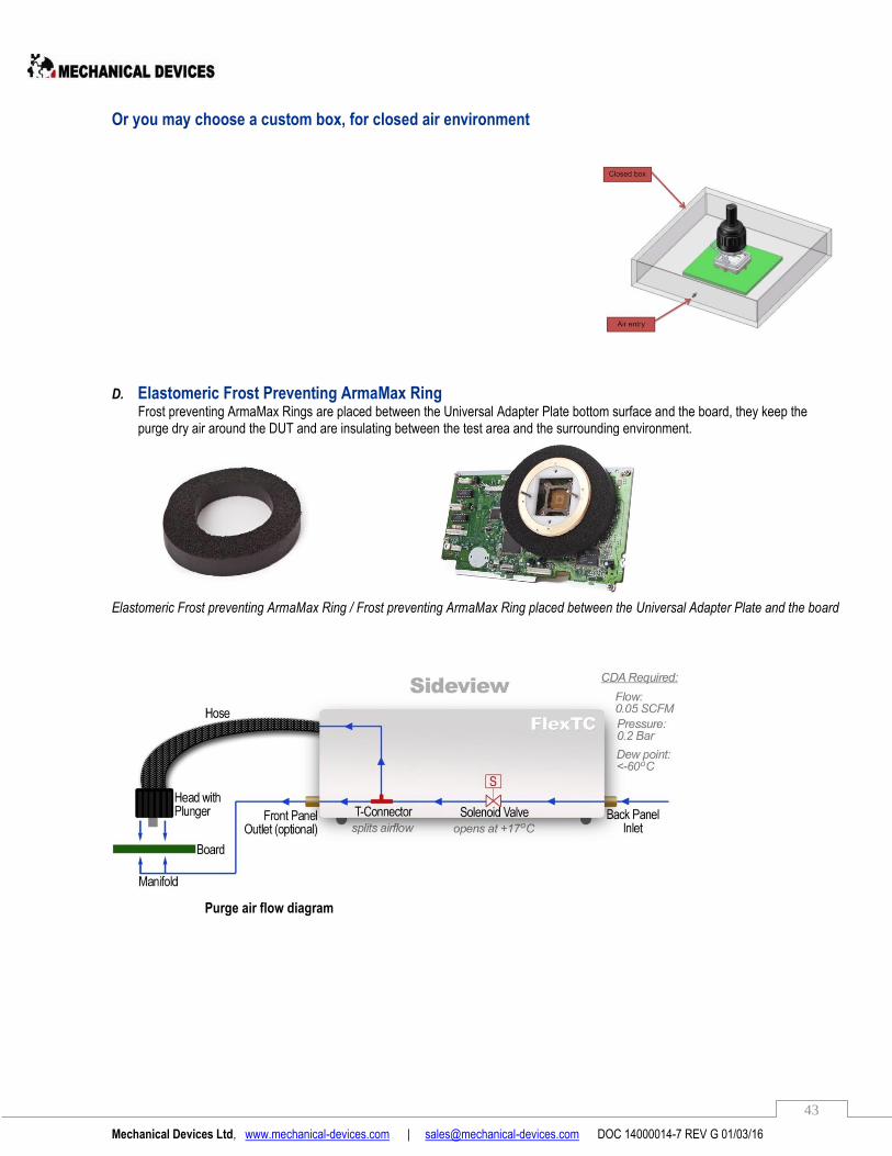
Or you may choose a custom box, for closed air environment
D. Elastomeric Frost Preventing ArmaMax Ring Frost preventing ArmaMax Rings are placed between the Universal Adapter Plate bottom surface and the board, they keep the purge dry air around the DUT and are insulating between the test area and the surrounding environment.
Elastomeric Frost preventing ArmaMax Ring / Frost preventing ArmaMax Ring placed between the Universal Adapter Plate and the board
Purge air flow diagram
Mechanical Devices Ltd, www.mechanical-devices.com | [email protected] DOC 14000014-7 REV G 01/03/16
44
FAQ
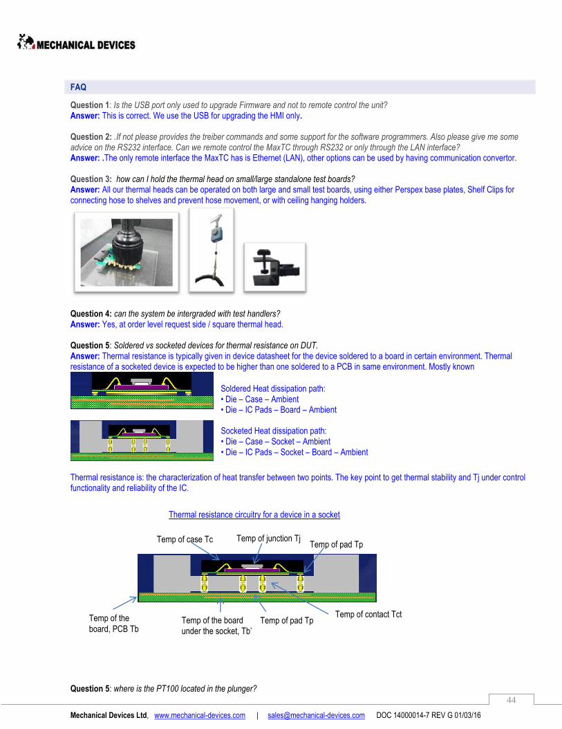
Question 1: Is the USB port only used to upgrade Firmware and not to remote control the unit? Answer: This is correct. We use the USB for upgrading the HMI only. Question 2: .If not please provides the treiber commands and some support for the software programmers. Also please give me some advice on the RS232 interface. Can we remote control the MaxTC through RS232 or only through the LAN interface? Answer: .The only remote interface the MaxTC has is Ethernet (LAN), other options can be used by having communication convertor. Question 3: how can I hold the thermal head on small/large standalone test boards? Answer: All our thermal heads can be operated on both large and small test boards, using either Perspex base plates, Shelf Clips for connecting hose to shelves and prevent hose movement, or with ceiling hanging holders.
Question 4: can the system be intergraded with test handlers? Answer: Yes, at order level request side / square thermal head. Question 5: Soldered vs socketed devices for thermal resistance on DUT. Answer: Thermal resistance is typically given in device datasheet for the device soldered to a board in certain environment. Thermal resistance of a socketed device is expected to be higher than one soldered to a PCB in same environment. Mostly known
Thermal resistance is: the characterization of heat transfer between two points. The key point to get thermal stability and Tj under control functionality and reliability of the IC. Question 5: where is the PT100 located in the plunger?
Soldered Heat dissipation path: • Die – Case – Ambient • Die – IC Pads – Board – Ambient Socketed Heat dissipation path: • Die – Case – Socket – Ambient • Die – IC Pads – Socket – Board – Ambient
Thermal resistance circuitry for a device in a socket
Temp of junction Tj Temp of pad Tp
Temp of case Tc
Temp of contact Tct Temp of pad Tp Temp of the board
under the socket, Tb’
Temp of the board, PCB Tb
Mechanical Devices Ltd, www.mechanical-devices.com | [email protected] DOC 14000014-7 REV G 01/03/16
45
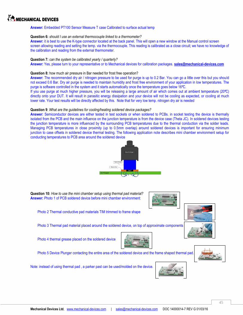
Answer: Embedded PT100 Sensor Measure T case Calibrated to surface actual temp Question 6: should I use an external thermocouple linked to a thermometer? Answer: it is best to use the K-type connector located at the back panel. This will open a new window at the Manual control screen screen allowing reading and setting the temp. via the thermocouple. This reading is calibrated as a close circuit; we have no knowledge of the calibration and reading from the external thermometer. Question 7: can the system be calibrated yearly / quarterly? Answer: Yes, please turn to your representative or to Mechanical devices for calibration packages. [email protected] Question 8: how much air pressure in Bar needed for frost free operation? Answer: The recommended dry air / nitrogen pressure to be used for purge is up to 0.2 Bar. You can go a little over this but you should not exceed 0.6 Bar. Dry air purge is needed to maintain humidity and frost free environment of your application in low temperatures. The purge is software controlled in the system and it starts automatically once the temperature goes below 16⁰C. If you use purge at much higher pressure, you will be releasing a large amount of air which comes out at ambient temperature (20⁰C) directly onto your DUT. It will result in parasitic energy dissipation and your device will not be cooling as expected, or cooling at much lower rate. Your test results will be directly affected by this. Note that for very low temp. nitrogen dry air is needed Question 9: What are the guidelines for cooling/heating soldered device packages? Answer: Semiconductor devices are either tested in test sockets or when soldered to PCBs. in socket testing the device is thermally isolated from the PCB and the main influence on the junction temperature is from the device case (Theta JC). In soldered devices testing the junction temperature is more influenced by the surrounding PCB temperatures due to the thermal conduction via the solder leads. Managing PCB temperatures in close proximity (up to 0.5mm overlap) around soldered devices is important for ensuring minimum junction to case offsets in soldered device thermal testing. The following application note describes mini chamber environment setup for conducting temperatures to PCB area around the soldered device
Question 10: How to use the mini chamber setup using thermal pad material? Answer: Photo 1 of PCB soldered device before mini chamber environment: Photo 2 Thermal conductive pad materials TIM trimmed to frame shape Photo 3 Thermal pad material placed around the soldered device, on top of approximate components Photo 4 thermal grease placed on the soldered device Photo 5 Device Plunger contacting the entire area of the soldered device and the frame shaped thermal pad. Note: instead of using thermal pad , a parker past can be used/molded on the device.

Mechanical Devices Ltd, www.mechanical-devices.com | [email protected] DOC 14000014-7 REV G 01/03/16
46
Mechanical Devices World Map
Mechanical Devices operates Worldwide in the above Countries
MECHANICAL DEVICES
Mechanical Devices – an advanced thermal solutions company is a global leader and innovator in temperature control solutions that are being used primarily by semiconductor manufacturers to test their IC and wafer processes, Mechanical Devices temperature control systems offer fast, accurate, stable and cost effective solutions, using advanced and patented technology. With the industry’s state-of-the-art temperature forcing systems, MaxTC and MaxTC, Mechanical Devices is changing the way the testing and temperature control is done, enabling semiconductor manufacturers to enhance their own profitability by improving the efficiency of their IC and wafer test processes Mechanical Devices end user customers include the world’s top semiconductor Manufacturers. The company’s products MaxTC and MaxTC systems can be integrated with the automatic test equipment (ATE) and handlers. Mechanical Devices is head-quartered in Haifa Bay, Israel with a branch in Santa Clara, CA, USA which includes its newest sales and service center Mechanical Devices has a number of sales representatives at key locations throughout Asia, Europe, and the United States
CONTACT US
Mechanical Devices Ltd 34 Ha’amelim Street, Haifa Bay 2624409, Israel +972-4-8490793 Mechanical Devices Inc 1800 Wyatt Dr. Suite 16 Santa Clara CA 95054, USA (408) 498-3608 www.mechanical-devices.com | [email protected]