Embed Size (px)
Citation preview
1
CE-632Foundation Analysis and Design
1
Design
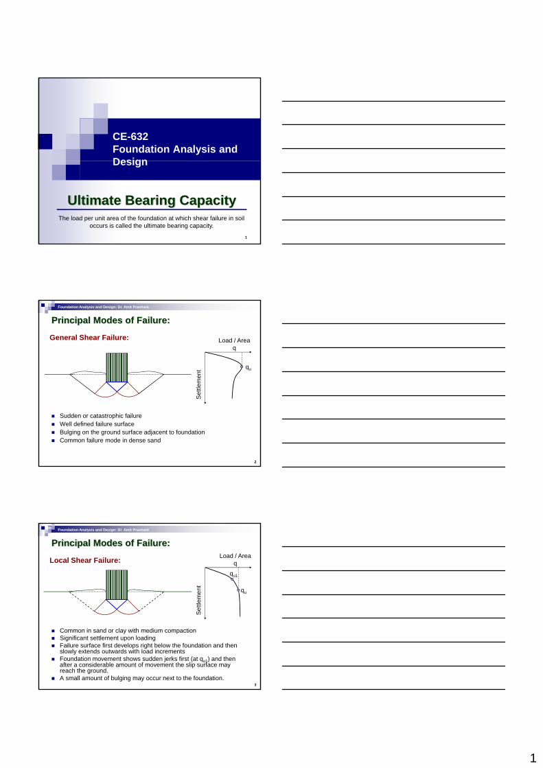
The load per unit area of the foundation at which shear failure in soil occurs is called the ultimate bearing capacity.
Ultimate Bearing Capacity
Foundation Analysis and Design: Dr. Amit Prashant
Principal Modes of Failure:
General Shear Failure: Load / Areaq
men
t qu
2
Settl
e
Sudden or catastrophic failureWell defined failure surfaceBulging on the ground surface adjacent to foundationCommon failure mode in dense sand
Foundation Analysis and Design: Dr. Amit Prashant
Principal Modes of Failure:
Local Shear Failure: Load / Areaq
ttlem
ent
qu
qu1
3
Set
Common in sand or clay with medium compactionSignificant settlement upon loadingFailure surface first develops right below the foundation and then slowly extends outwards with load incrementsFoundation movement shows sudden jerks first (at qu1) and then after a considerable amount of movement the slip surface may reach the ground.A small amount of bulging may occur next to the foundation.
2
Foundation Analysis and Design: Dr. Amit Prashant
Principal Modes of Failure:
Punching Failure:Load / Area
q
ttlem
ent qu
qu1
4
Set
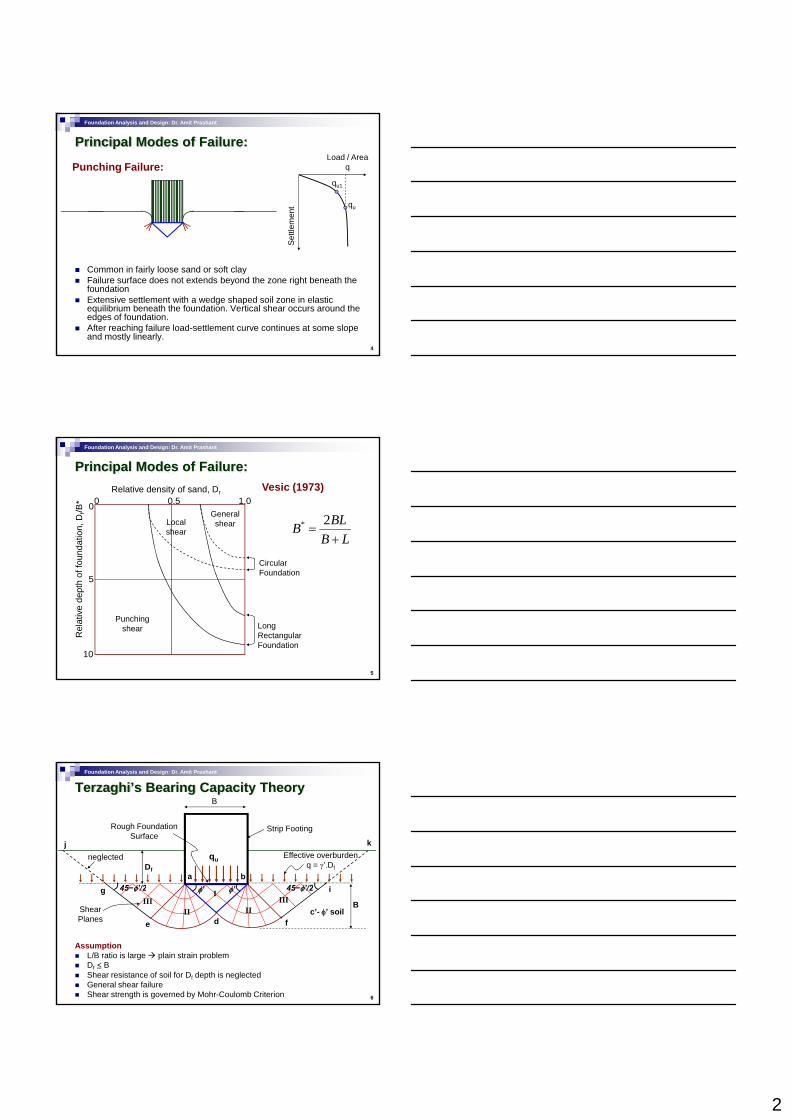
Common in fairly loose sand or soft clay Failure surface does not extends beyond the zone right beneath the foundationExtensive settlement with a wedge shaped soil zone in elastic equilibrium beneath the foundation. Vertical shear occurs around the edges of foundation.After reaching failure load-settlement curve continues at some slope and mostly linearly.
Foundation Analysis and Design: Dr. Amit Prashant
Principal Modes of Failure:
Local shear
General shear
unda
tion,
Df/B
*
Relative density of sand, Dr00 0.5 1.0
Vesic (1973)
* 2BLBB L
=+
5
Circular Foundation
Long Rectangular Foundation
Punching shear
Rel
ativ
e de
pth
of fo
u
5
10
Foundation Analysis and Design: Dr. Amit Prashant
Terzaghi’s Bearing Capacity TheoryB
Df
neglected Effective overburdenq = γ’.Df
Strip Footing
a b
j kqu
Rough Foundation Surface
6
Assumption L/B ratio is large plain strain problemDf ≤ BShear resistance of soil for Df depth is neglectedGeneral shear failureShear strength is governed by Mohr-Coulomb Criterion
φ’ φ’45−φ’/2 45−φ’/2
Shear Planes de f
g i
c’- φ’ soilB
I
II IIIII III
3
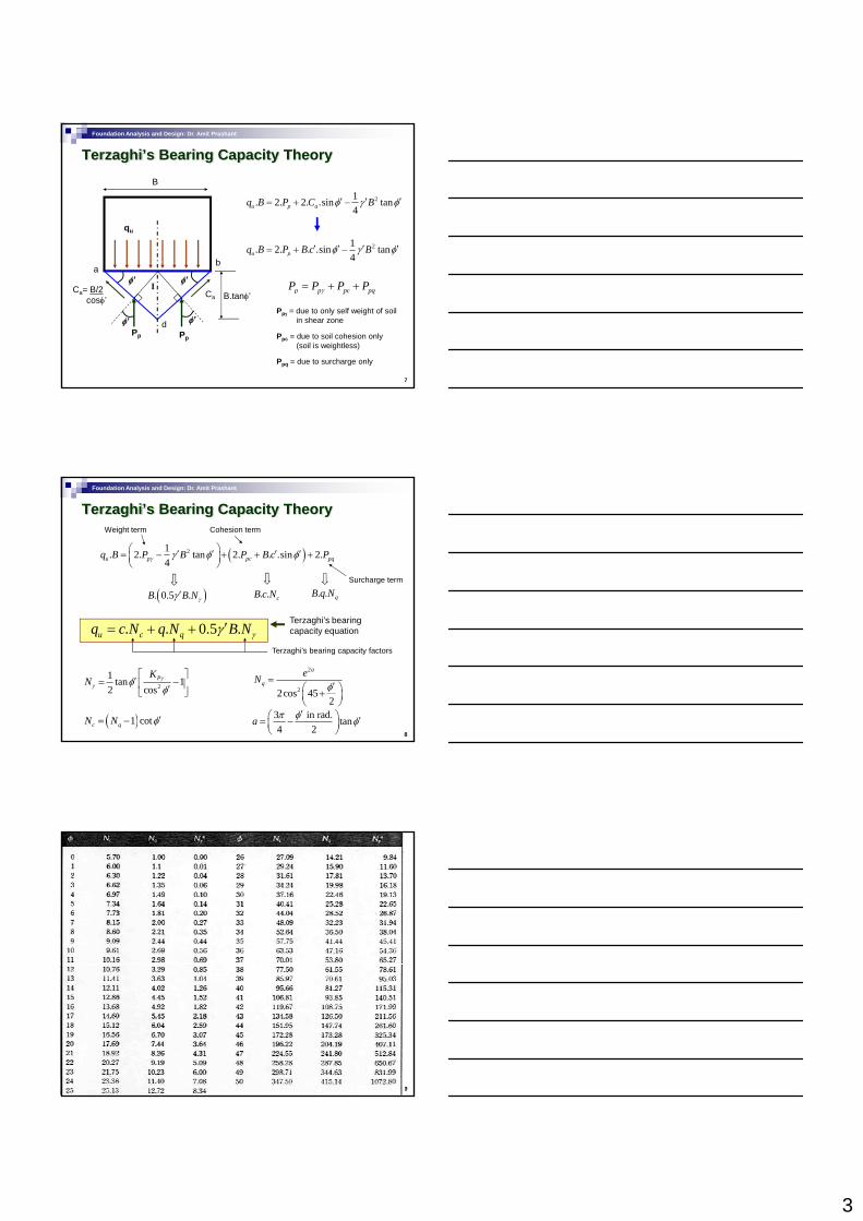
Foundation Analysis and Design: Dr. Amit Prashant
Terzaghi’s Bearing Capacity Theory
21. 2. 2. .sin tan4u p aq B P C Bφ γ φ′ ′ ′= + −
21. 2. . .sin tan4u pq B P B c Bφ γ φ′ ′ ′ ′= + −
B
qu
7
4p
Iφ’ φ’
ab
dφ’ φ’
Ca= B/2cosφ’
Ca B.tanφ’
Pp Pp
Ppγ = due to only self weight of soil in shear zone
p p pc pqP P P Pγ= + +
Ppc = due to soil cohesion only (soil is weightless)
Ppq = due to surcharge only
Foundation Analysis and Design: Dr. Amit Prashant
Terzaghi’s Bearing Capacity Theory
( )21. 2. tan 2. . .sin 2.4u p pc pqq B P B P B c Pγ γ φ φ⎛ ⎞′ ′ ′ ′= − + + +⎜ ⎟
⎝ ⎠
Weight term Cohesion term
Surcharge term
( ). 0.5 .B B Nγγ ′ . . cB c N . . qB q N
8
2
1 tan 12 cos
PKN γ
γ φφ
⎡ ⎤′= −⎢ ⎥′⎣ ⎦
2
22cos 452
a
qeN
φ=
′⎛ ⎞+⎜ ⎟⎝ ⎠
3 in rad. tan4 2
a π φ φ′⎛ ⎞ ′= −⎜ ⎟
⎝ ⎠( )1 cotc qN N φ′= −
. . 0.5 .u c qq c N q N B Nγγ ′= + +Terzaghi’s bearing capacity equation
Terzaghi’s bearing capacity factors
Foundation Analysis and Design: Dr. Amit Prashant
9
4
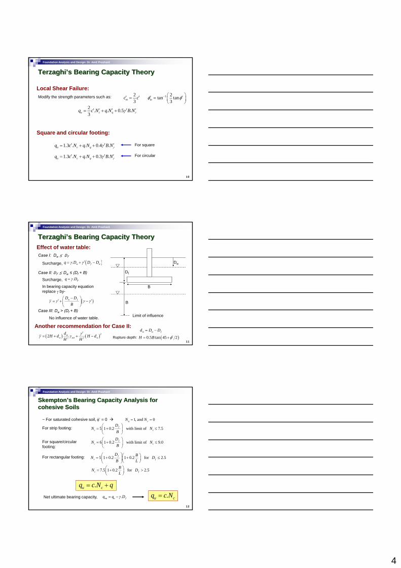
Foundation Analysis and Design: Dr. Amit Prashant
Terzaghi’s Bearing Capacity Theory
Local Shear Failure:
2 . . 0.5 .3u c qq c N q N B Nγγ′ ′ ′ ′ ′= + +
Modify the strength parameters such as: 23mc c′ ′= 1 2tan tan
3mφ φ− ⎛ ⎞′ ′= ⎜ ⎟⎝ ⎠
10
Square and circular footing:
1.3 . . 0.4 .u c qq c N q N B Nγγ′ ′ ′= + +
1.3 . . 0.3 .u c qq c N q N B Nγγ′ ′ ′= + +
For square
For circular
Foundation Analysis and Design: Dr. Amit Prashant
Terzaghi’s Bearing Capacity TheoryEffect of water table:
Dw
Df
Case I: Dw ≤ Df
Surcharge, ( ). w f wq D D Dγ γ ′= + −
Case II: Df ≤ Dw ≤ (Df + B)
Surcharge, . Fq Dγ=
11
B
B
Limit of influence
In bearing capacity equation replace γ by-
( )w fD DB
γ γ γ γ−⎛ ⎞
′ ′= + −⎜ ⎟⎝ ⎠
Case III: Dw > (Df + B)
No influence of water table.
Another recommendation for Case II:
( ) ( )22 22 w
w sat wdH d H dH H
γγ γ′
= + + −w w fd D D= −
( )0.5 tan 45 2H B φ′= +Rupture depth:
Foundation Analysis and Design: Dr. Amit Prashant
Skempton’s Bearing Capacity Analysis for cohesive Soils
~ For saturated cohesive soil, φ‘ = 0 1, and 0qN Nγ= =
For strip footing: 5 1 0.2 with limit of 7.5fc c
DN N
B⎛ ⎞
= + ≤⎜ ⎟⎝ ⎠
For square/circular footing:
6 1 0.2 with limit of 9.0fc c
DN N
B⎛ ⎞
= + ≤⎜ ⎟⎝ ⎠
12
g
For rectangular footing: 5 1 0.2 1 0.2 for 2.5fc f
D BN DB L
⎛ ⎞⎛ ⎞= + + ≤⎜ ⎟⎜ ⎟⎝ ⎠⎝ ⎠
7.5 1 0.2 for 2.5c fBN DL
⎛ ⎞= + >⎜ ⎟⎝ ⎠
.u cq c N q= +
Net ultimate bearing capacity, .nu u fq q Dγ= − .u cq c N=
5
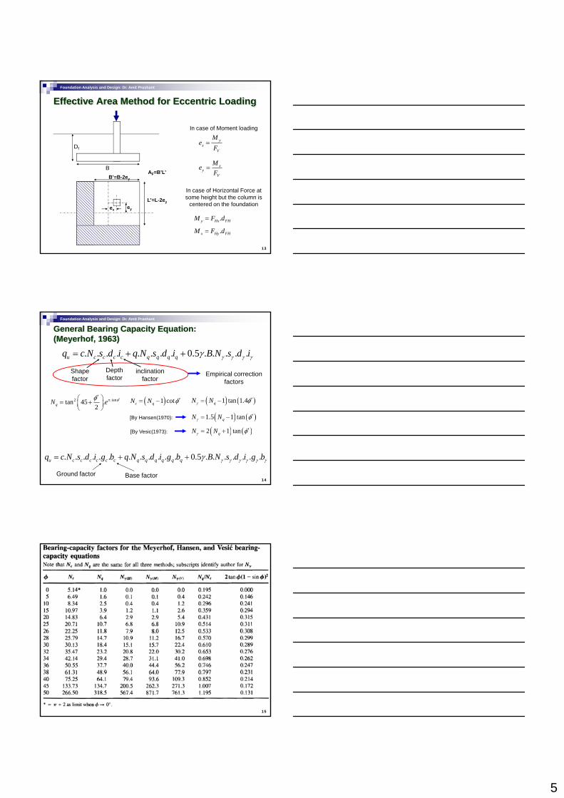
Foundation Analysis and Design: Dr. Amit Prashant
Effective Area Method for Eccentric Loading
B
Df
yx
V
Me
F=
xMe
In case of Moment loading
13
B
eyex
L’=L-2ey
B’=B-2ey
AF=B’L’x
yV
eF
=
In case of Horizontal Force at some height but the column is
centered on the foundation
.y Hx FHM F d=
.x Hy FHM F d=
Foundation Analysis and Design: Dr. Amit Prashant
General Bearing Capacity Equation: (Meyerhof, 1963)
. . . . . . . . 0.5 . . . . .u c c c c q q q qq c N s d i q N s d i B N s d iγ γ γ γγ= + +
Shape factor
Depth factor
inclination factor
Empirical correction factors
2 φφ ′′⎛ ⎞ ( )1N N φ′ ( ) ( )1 1 4N N φ′
14
2 .tantan 45 .2qN eπ φφ ′⎛ ⎞= +⎜ ⎟
⎝ ⎠( )1 cotc qN N φ′= − ( ) ( )1 tan 1.4qN Nγ φ′= −
( ) ( )2 1 tanqN Nγ φ′= +
( ) ( )1.5 1 tanqN Nγ φ′= −
[By Vesic(1973):
[By Hansen(1970):
. . . . . . . . . . . . 0.5 . . . . . . .u c c c c c c q q q q q qq c N s d i g b q N s d i g b B N s d i g bγ γ γ γ γ γγ= + +
Ground factor Base factor
Foundation Analysis and Design: Dr. Amit Prashant
15
6
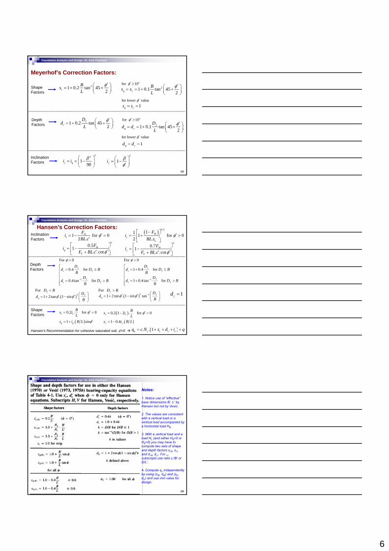
Foundation Analysis and Design: Dr. Amit Prashant
Meyerhof’s Correction Factors:
Shape Factors
21 0.2 tan 452c
BsL
φ′⎛ ⎞= + +⎜ ⎟⎝ ⎠
21 0.1 tan 452q
Bs sLγ
φ′⎛ ⎞= = + +⎜ ⎟⎝ ⎠
for 10oφ′ ≥
1qs sγ= =for lower valueφ′
16
Depth Factors 1 0.2 tan 45
2f
c
Dd
Lφ′⎛ ⎞= + +⎜ ⎟
⎝ ⎠ 1 0.1 tan 452
fq
Dd d
Lγφ′⎛ ⎞= = + +⎜ ⎟
⎝ ⎠
for 10oφ′ ≥
1qd dγ= =for lower valueφ′
Inclination Factors
2
190
o
c qi i β⎛ ⎞= = −⎜ ⎟
⎝ ⎠
2
1iγβφ
⎛ ⎞= −⎜ ⎟′⎝ ⎠
Foundation Analysis and Design: Dr. Amit Prashant
Hansen’s Correction Factors:1 for 0
2 .H
cFiBL c
φ′= − =′
( ) 1/211 1 for 0
2 .H
cu
Fi
BL sφ
⎡ ⎤−′= + >⎢ ⎥
⎣ ⎦
For 0
0.4 for fc f
Dd D B
B
φ =
⎡= ≤⎢
⎢
For 0
1 0.4 for fc f
Dd D B
B
φ >
⎡= + ≤⎢
⎢
Inclination Factors
50.51
. .cotH
qV
FiF BL c φ
⎡ ⎤= −⎢ ⎥′ ′+⎣ ⎦
50.71
. .cotH
V
FiF BL cγ φ
⎡ ⎤= −⎢ ⎥′ ′+⎣ ⎦
Depth Factors
Shape Factors
1
0.4 tan for f
c f
Dd D B
B−
⎢⎢
= >⎢⎣11 0.4 tan for f
c f
Dd D B
B−
⎢⎢
= + >⎢⎣
For fD B< For fD B>1dγ =
0.2 . for 0c cBs iL
φ′= =
( )1 . sinq qs i B L φ′= +
( )0.2 1 2 . for 0c cBs iL
φ′= − >
( )1 0.4 .s i B Lγ γ= −
Hansen’s Recommendation for cohesive saturated soil, φ'=0 ( ). . 1u c c c cq c N s d i q= + + + +
( )21 2 tan . 1 sin fq
Dd
Bφ φ
⎛ ⎞′ ′= + − ⎜ ⎟
⎝ ⎠( )2 11 2 tan . 1 sin tan f
q
Dd
Bφ φ − ⎛ ⎞
′ ′= + − ⎜ ⎟⎝ ⎠
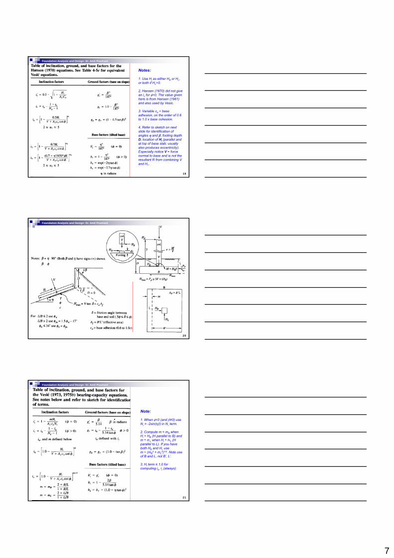
Foundation Analysis and Design: Dr. Amit Prashant
Notes:
1. Notice use of “effective” base dimensions B‘, L‘ by Hansen but not by Vesic.
2. The values are consistent with a vertical load or a vertical load accompanied by a horizontal load HB.
3. With a vertical load and a
18
3. With a vertical load and a load HL (and either HB=0 or HB>0) you may have to compute two sets of shape and depth factors si,B, si,Land di,B, di,L. For i,Lsubscripts use ratio L‘/B‘ or D/L‘.
4. Compute qu independently by using (siB, diB) and (siL, diL) and use min value for design.
7
Foundation Analysis and Design: Dr. Amit Prashant
Notes:
1. Use Hi as either HB or HL, or both if HL>0.
2. Hansen (1970) did not give an ic for φ>0. The value given here is from Hansen (1961) and also used by Vesic.
3. Variable ca = base adhesion, on the order of 0.6
19
,to 1.0 x base cohesion.
4. Refer to sketch on next slide for identification of angles η and β, footing depth D, location of Hi (parallel and at top of base slab; usually also produces eccentricity). Especially notice V = force normal to base and is not the resultant R from combining V and Hi..
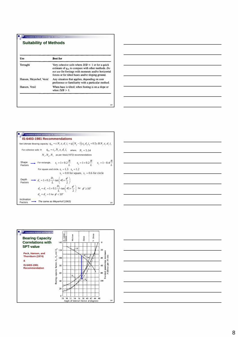
Foundation Analysis and Design: Dr. Amit Prashant
20
Foundation Analysis and Design: Dr. Amit Prashant
Note:
1. When φ=0 (and β≠0) use Nγ = -2sin(±β) in Nγ term.
2. Compute m = mB when Hi = HB (H parallel to B) and m = mL when Hi = HL (H
21
m mL when Hi HL (H parallel to L). If you have both HB and HL use m = (mB
2 + mL2)1/2. Note use
of B and L, not B’, L’.
3. Hi term ≤ 1.0 for computing iq, iγ (always).
8
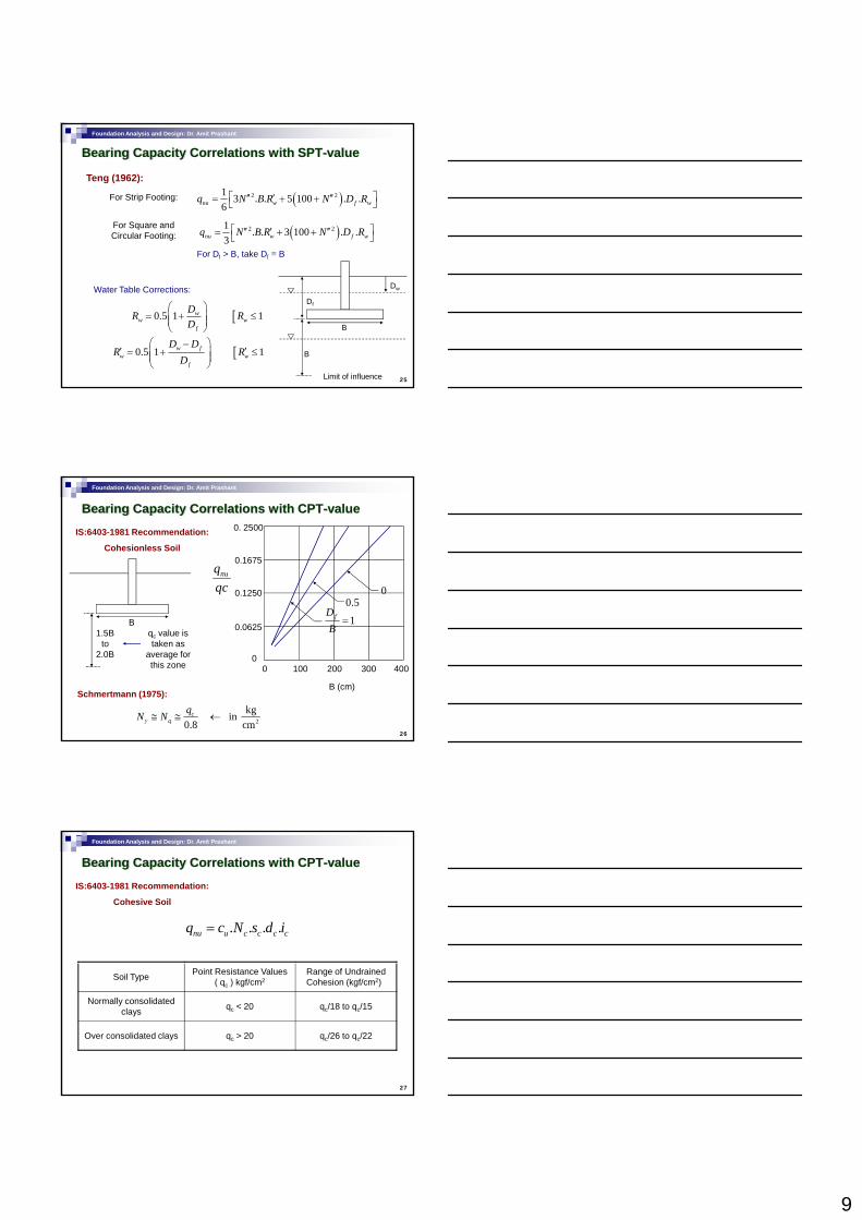
Foundation Analysis and Design: Dr. Amit Prashant
Suitability of Methods
22
Foundation Analysis and Design: Dr. Amit Prashant
IS:6403-1981 Recommendations
Shape Factors
Net Ultimate Bearing capacity: ( ). . . . . 1 . . . 0.5 . . . . .nu c c c c q q q qq c N s d i q N s d i B N s d iγ γ γ γγ= + − +
. . . .nu u c c c cq c N s d i= 5.14cN =For cohesive soils where,
, ,c qN N Nγ as per Vesic(1973) recommendations
1 0.2cBsL
= + 1 0.2qBsL
= + 1 0.4 BsLγ = −For rectangle,
1 3 1 2
23
1 0.2 tan 452
fc
Dd
Lφ′⎛ ⎞= + +⎜ ⎟
⎝ ⎠
1 0.1 tan 452
fq
Dd d
Lγφ′⎛ ⎞= = + +⎜ ⎟
⎝ ⎠
Inclination Factors
Depth Factors
1.3cs = 1.2qs =0.8 for square, 0.6 for circles sγ γ= =
For square and circle,
for 10oφ′ ≥
1qd dγ= = for 10oφ′ <
The same as Meyerhof (1963)
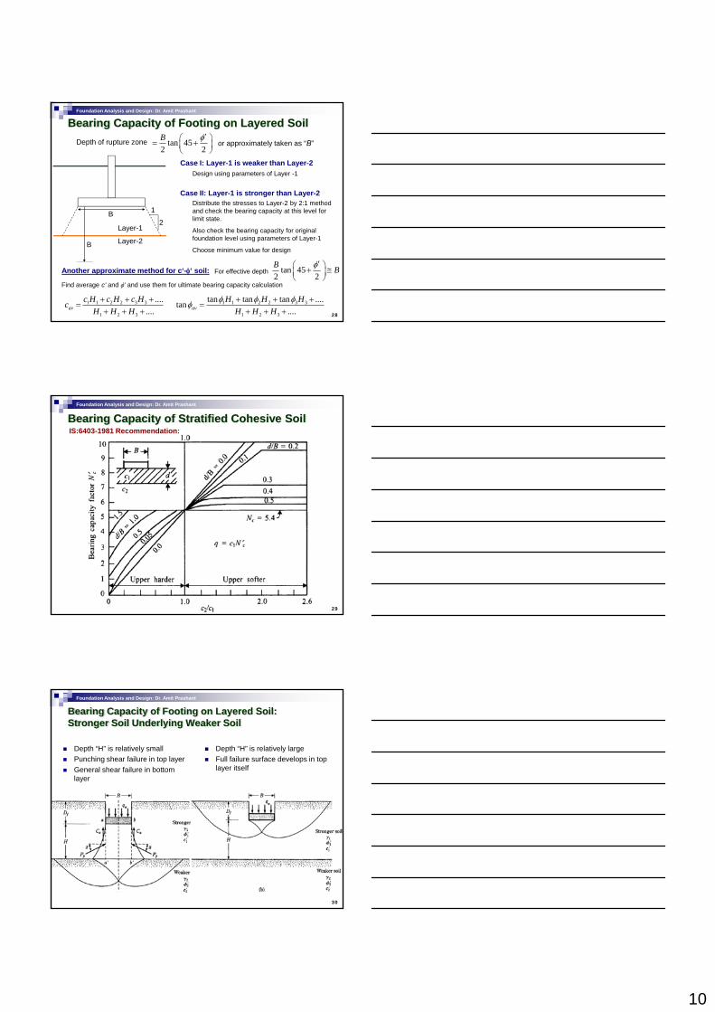
Foundation Analysis and Design: Dr. Amit Prashant
Bearing Capacity Correlations with SPT-value
Peck, Hansen, and Thornburn (1974)
&
IS:6403-1981
24
Recommendation
9
Foundation Analysis and Design: Dr. Amit Prashant
Bearing Capacity Correlations with SPT-value
Teng (1962):
( )2 21 3 . . 5 100 . .6nu w f wq N B R N D R⎡ ⎤′′ ′ ′′= + +⎣ ⎦
For Strip Footing:
( )2 21 . . 3 100 . .3nu w f wq N B R N D R⎡ ⎤′′ ′ ′′= + +⎣ ⎦
For Square and Circular Footing:
For Df > B take Df = B
25
For Df > B, take Df B
[0.5 1 1ww w
f
DR RD
⎛ ⎞= + ≤⎜ ⎟⎜ ⎟
⎝ ⎠
[0.5 1 1w fw w
f
D DR R
D⎛ ⎞−
′ ′= + ≤⎜ ⎟⎜ ⎟⎝ ⎠
Water Table Corrections:
B
B
Dw
Df
Limit of influence
Foundation Analysis and Design: Dr. Amit Prashant
Bearing Capacity Correlations with CPT-value
0.1250
0.1675
0. 2500
nuqqc
D0.5
0
IS:6403-1981 Recommendation:
Cohesionless Soil
26
0 100 200 300 4000
0.0625
B (cm)
1fDB
=1.5B
to 2.0B
Bqc value is taken as
average for this zone
Schmertmann (1975):
2
kg in 0.8 cm
cq
qN Nγ ≅ ≅ ←
Foundation Analysis and Design: Dr. Amit Prashant
Bearing Capacity Correlations with CPT-value
IS:6403-1981 Recommendation:
Cohesive Soil
. . . .nu u c c c cq c N s d i=
27
Soil Type Point Resistance Values( qc ) kgf/cm2
Range of Undrained Cohesion (kgf/cm2)
Normally consolidated clays qc < 20 qc/18 to qc/15
Over consolidated clays qc > 20 qc/26 to qc/22
10
Foundation Analysis and Design: Dr. Amit Prashant
Bearing Capacity of Footing on Layered SoilDepth of rupture zone tan 45
2 2B φ′⎛ ⎞= +⎜ ⎟
⎝ ⎠or approximately taken as “B”
Case I: Layer-1 is weaker than Layer-2
B 1
Design using parameters of Layer -1
Case II: Layer-1 is stronger than Layer-2Distribute the stresses to Layer-2 by 2:1 method and check the bearing capacity at this level for
28
B2
1
B
Layer-1
Layer-2
and check the bearing capacity at this level for limit state.
Also check the bearing capacity for original foundation level using parameters of Layer-1
Choose minimum value for design
Another approximate method for c‘-φ‘ soil: For effective depth tan 452 2B Bφ′⎛ ⎞+ ≅⎜ ⎟
⎝ ⎠Find average c‘ and φ‘ and use them for ultimate bearing capacity calculation
1 1 2 2 3 3
1 2 3
........av
c H c H c HcH H H
+ + +=
+ + +1 1 2 2 3 3
1 2 3
tan tan tan ....tan....av
H H HH H H
φ φ φφ + + +=
+ + +
Foundation Analysis and Design: Dr. Amit Prashant
Bearing Capacity of Stratified Cohesive SoilIS:6403-1981 Recommendation:
29
Foundation Analysis and Design: Dr. Amit Prashant
Bearing Capacity of Footing on Layered Soil:Stronger Soil Underlying Weaker Soil
Depth “H” is relatively smallPunching shear failure in top layerGeneral shear failure in bottom layer
Depth “H” is relatively largeFull failure surface develops in top layer itself
30
11
Foundation Analysis and Design: Dr. Amit Prashant
Bearing Capacity of Footing on Layered Soil:Stronger Soil Underlying Weaker Soil
31
Foundation Analysis and Design: Dr. Amit Prashant
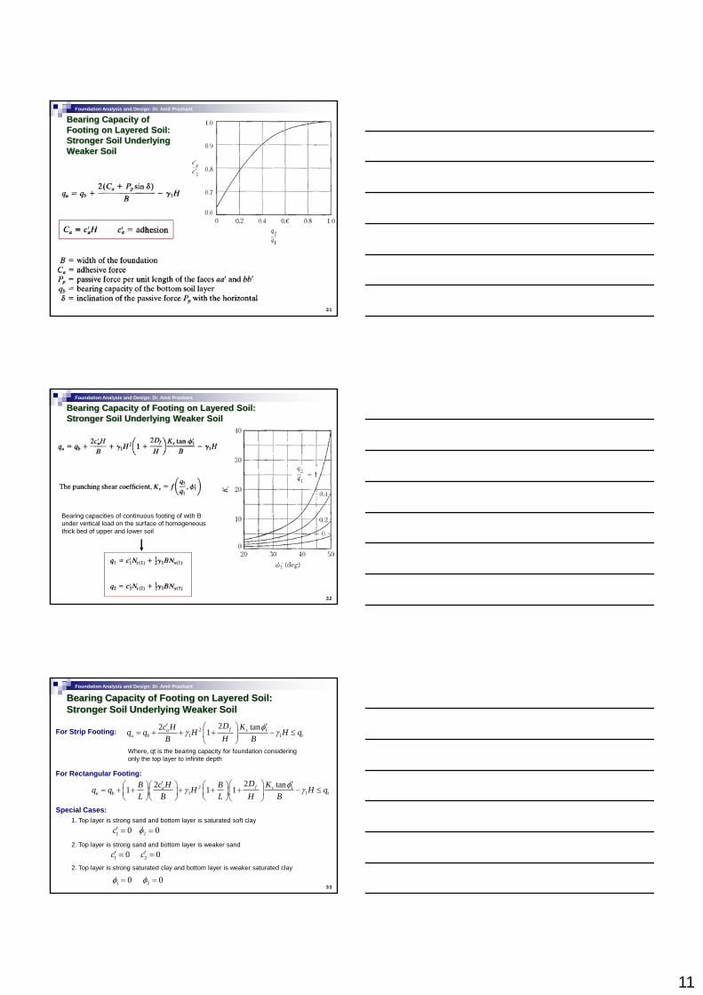
Bearing Capacity of Footing on Layered Soil:Stronger Soil Underlying Weaker Soil
32
Bearing capacities of continuous footing of with B under vertical load on the surface of homogeneous thick bed of upper and lower soil
Foundation Analysis and Design: Dr. Amit Prashant
Bearing Capacity of Footing on Layered Soil:Stronger Soil Underlying Weaker Soil
For Strip Footing:
Where, qt is the bearing capacity for foundation considering only the top layer to infinite depth
For Rectangular Footing:
2 11 1
22 tan1 fa su b t
Dc H Kq q H H qB H B
φγ γ′ ′⎛ ⎞
= + + + − ≤⎜ ⎟⎝ ⎠
2 22 tanfDc H KB B φ′ ′⎛ ⎞⎛ ⎞⎛ ⎞ ⎛ ⎞
33
2 11 1
22 tan1 1 1 fa su b t
Dc H KB Bq q H H qL B L H B
φγ γ⎛ ⎞⎛ ⎞⎛ ⎞ ⎛ ⎞= + + + + + − ≤⎜ ⎟⎜ ⎟ ⎜ ⎟⎜ ⎟
⎝ ⎠ ⎝ ⎠⎝ ⎠ ⎝ ⎠Special Cases:
1. Top layer is strong sand and bottom layer is saturated soft clay
2 0φ =
2. Top layer is strong sand and bottom layer is weaker sand
1 0c′ =
1 0c′ = 2 0c′ =2. Top layer is strong saturated clay and bottom layer is weaker saturated clay
2 0φ =1 0φ =
12
Foundation Analysis and Design: Dr. Amit Prashant
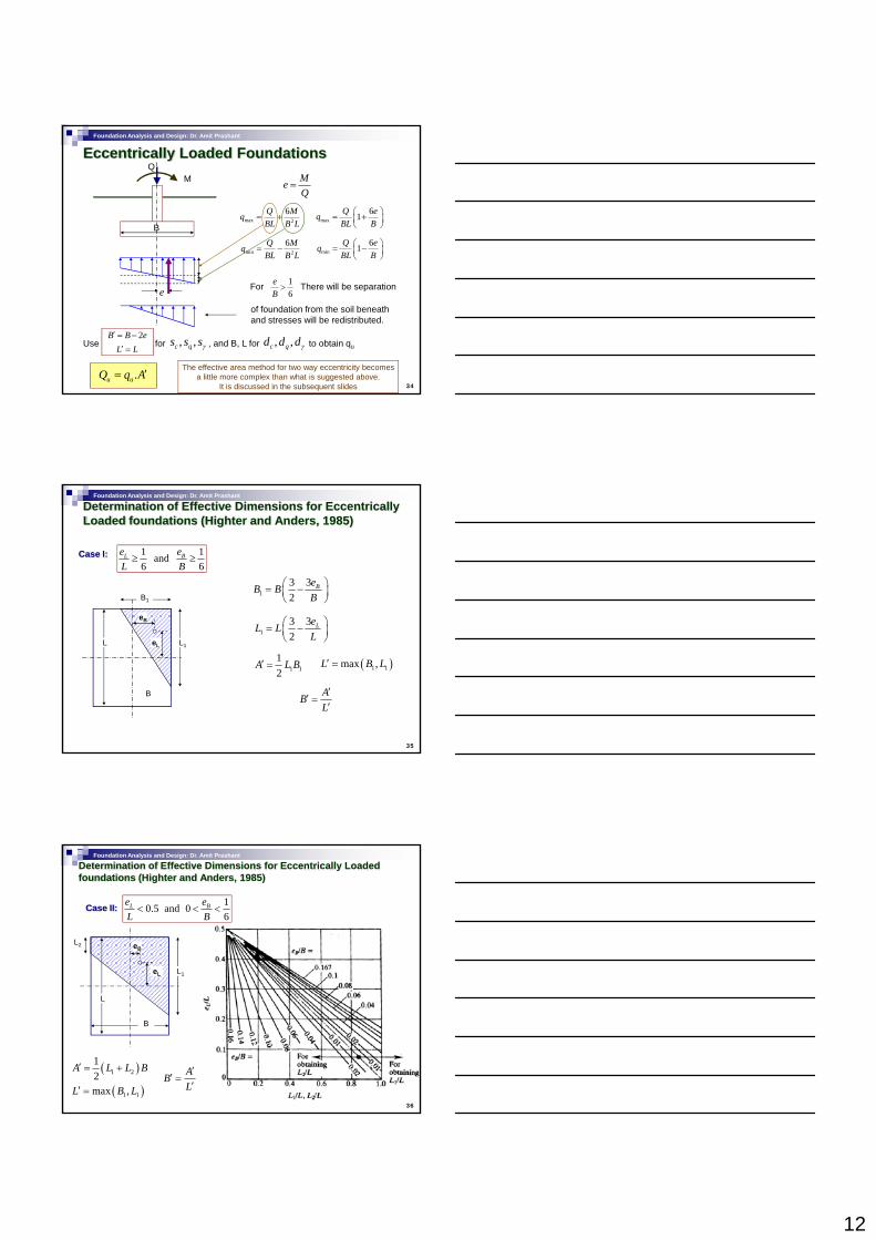
Eccentrically Loaded Foundations
B
MQ
max 2
6Q MqBL B L
= +
MeQ
=
min 26Q Mq
BL B L= −
max61Q eq
BL B⎛ ⎞= +⎜ ⎟⎝ ⎠
min61Q eq
BL B⎛ ⎞= −⎜ ⎟⎝ ⎠
34
e
⎝ ⎠
16
eB
>For There will be separation
of foundation from the soil beneath and stresses will be redistributed.
Use for , and B, L for to obtain qu, ,c qd d dγ2B B e′ = −
L L′ =, ,c qs s sγ
.u uQ q A′=The effective area method for two way eccentricity becomes
a little more complex than what is suggested above. It is discussed in the subsequent slides
Foundation Analysis and Design: Dr. Amit Prashant
Determination of Effective Dimensions for Eccentrically Loaded foundations (Highter and Anders, 1985)
Case I: 1 1 and 6 6
L Be eL B
≥ ≥
133
2BeB B
B⎛ ⎞= −⎜ ⎟⎝ ⎠
33⎛ ⎞eB
B1
35
133
2LeL L
L⎛ ⎞= −⎜ ⎟⎝ ⎠
1 112
A L B′ =
ABL
′′ =
′
( )1 1max ,L B L′ =
eL
eB
L1L
B
Foundation Analysis and Design: Dr. Amit Prashant
Case II: 10.5 and 06
L Be eL B
< < <
eL
eB
L1
L2
Determination of Effective Dimensions for Eccentrically Loaded foundations (Highter and Anders, 1985)
36
( )1 212
A L L B′ = + ABL
′′ =
′( )1 1max ,L B L′ =
L
B
13
Foundation Analysis and Design: Dr. Amit Prashant
Determination of Effective Dimensions for Eccentrically Loaded foundations (Highter and Anders, 1985)
Case III: 1 and 0 0.56
L Be eL B
< < <
eB
B1
37
( )1 212
A L B B′ = + ABL
′′ =
′L L′ =
eL
L
B
B2
Foundation Analysis and Design: Dr. Amit Prashant
Determination of Effective Dimensions for Eccentrically Loaded foundations (Highter and Anders, 1985)
Case IV:
B1
e
eB
1 1 and 6 6
L Be eL B
< <
38
ABL
′′ =
′L L′ =
eL
L
B
B2
( )( )2 1 2 212
A L B B B L L′ = + + +
Foundation Analysis and Design: Dr. Amit Prashant
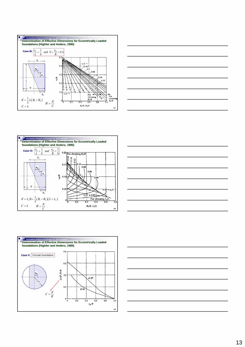
Determination of Effective Dimensions for Eccentrically Loaded foundations (Highter and Anders, 1985)
Case V: Circular foundation
eR
39
ALB
′′ =
′
R
R
14
Foundation Analysis and Design: Dr. Amit Prashant
Meyerhof’s (1953) area correction based on empirical correlations: (American Petroleum Institute, 1987)
40
Foundation Analysis and Design: Dr. Amit Prashant
Bearing Capacity of Footings on SlopesMeyerhof’s (1957) Solution
0.5u cq qq c N BNγγ′= +
41
0c′ =Granular Soil
0.5u qq BNγγ=
Foundation Analysis and Design: Dr. Amit Prashant
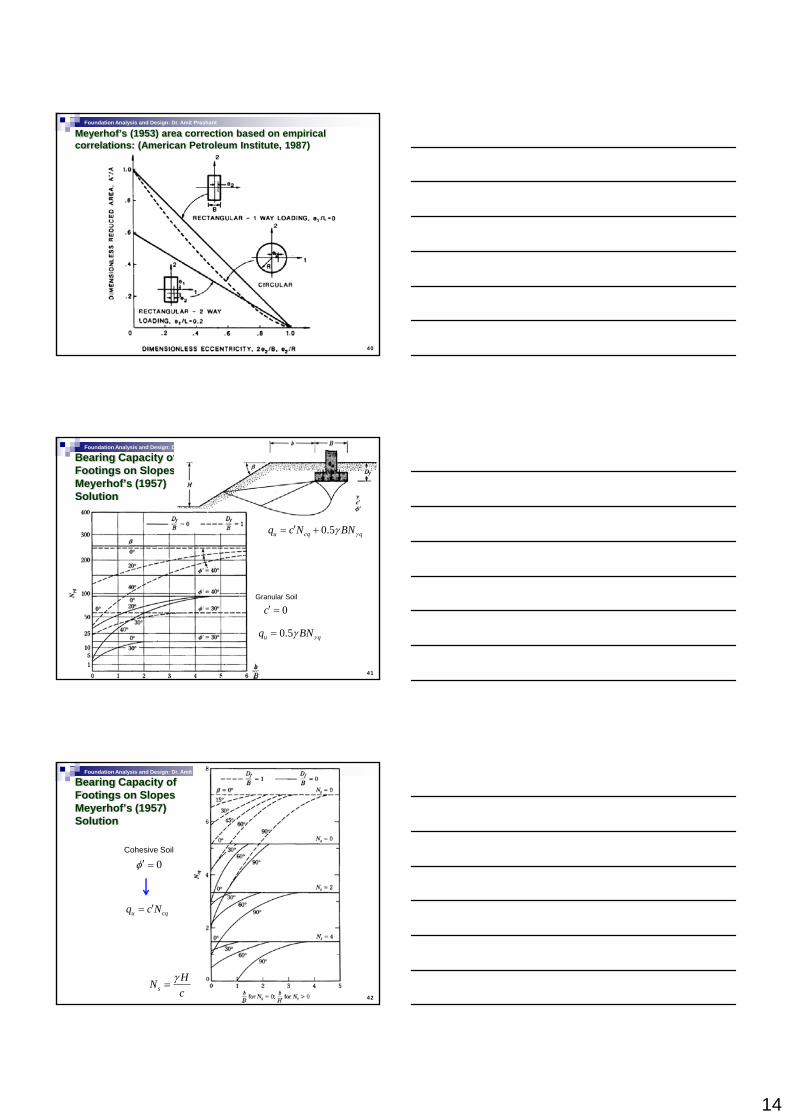
Bearing Capacity of Footings on SlopesMeyerhof’s (1957) Solution
0φ′ =Cohesive Soil
42
u cqq c N′=
sHNc
γ=
15
Foundation Analysis and Design: Dr. Amit Prashant
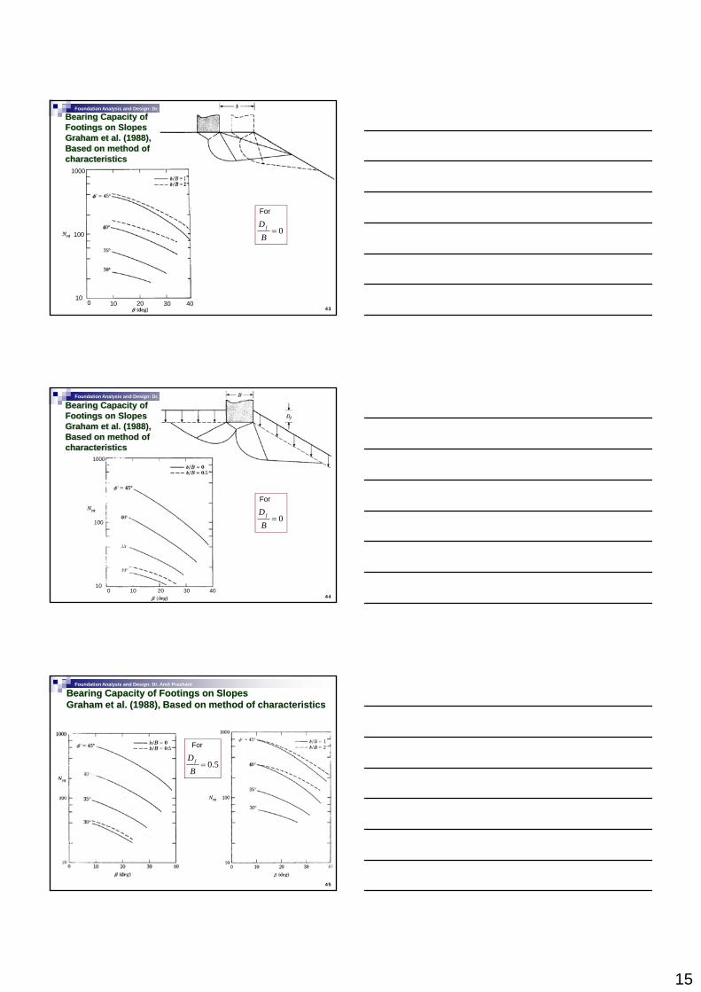
Bearing Capacity of Footings on SlopesGraham et al. (1988), Based on method of characteristics
1000
43
For
0fDB
=100
100 10 20 30 40
Foundation Analysis and Design: Dr. Amit Prashant
Bearing Capacity of Footings on SlopesGraham et al. (1988), Based on method of characteristics
1000
44
100
100 10 20 30 40
For
0fDB
=
Foundation Analysis and Design: Dr. Amit Prashant
Bearing Capacity of Footings on SlopesGraham et al. (1988), Based on method of characteristics
For
0.5fDB
=
45
16
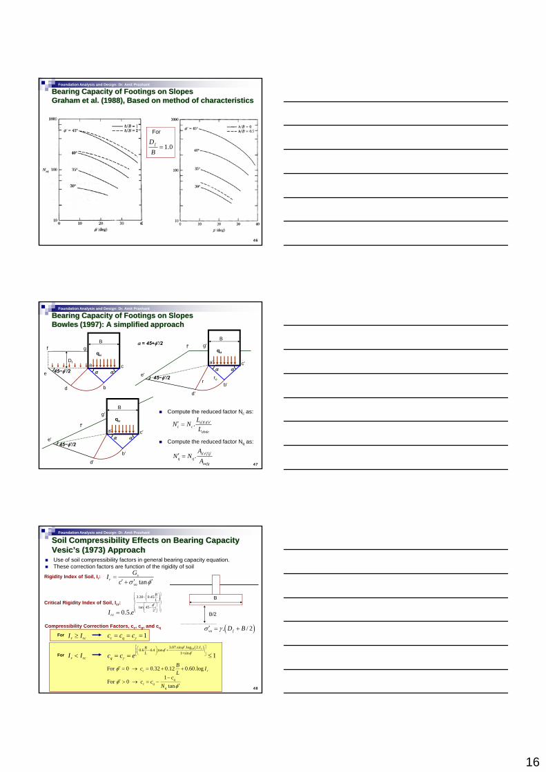
Foundation Analysis and Design: Dr. Amit Prashant
Bearing Capacity of Footings on SlopesGraham et al. (1988), Based on method of characteristics
For
1.0fDB
=
46
Foundation Analysis and Design: Dr. Amit Prashant
Bearing Capacity of Footings on SlopesBowles (1997): A simplified approach
B
Df
α α45−φ’/2a c
e
fqu
gα = 45+φ’/2
B
α α
45−φ’/2
a'
b'
c'
e'
g'qu
f'
ror
47
bd
Compute the reduced factor Nc as:
Compute the reduced factor Nq as:
. a b d ec c
abde
LN NL
′ ′ ′ ′′ =
. a e f gq q
aefg
AN N
A′ ′ ′ ′′ =
B
α α45−φ’/2
a'
b'
c'e'
g'qu
d'
f'
b
d'
Foundation Analysis and Design: Dr. Amit Prashant
Soil Compressibility Effects on Bearing CapacityVesic’s (1973) ApproachUse of soil compressibility factors in general bearing capacity equation.These correction factors are function of the rigidity of soil
tans
rvo
GIc σ φ
=′ ′ ′+
Rigidity Index of Soil, Ir:
BCritical Rigidity Index of Soil, Icr:
3.30 0.45
tan 452
BL
φ
⎧ ⎫⎛ ⎞−⎜ ⎟⎪ ⎪⎪ ⎪⎝ ⎠⎨ ⎬′⎡ ⎤⎪ ⎪−⎢ ⎥⎪ ⎪⎣ ⎦⎩ ⎭
48
B/2
( ). / 2vo fD Bσ γ′ = +
20.5.rcI e⎢ ⎥⎪ ⎪⎣ ⎦⎩ ⎭=
Compressibility Correction Factors, cc, cg, and cq
r rcI I≥For 1c qc c cγ= = =
r rcI I<( )103.07.sin .log 2.
0.6 4.4 .tan1 sin 1
rIBL
qc c eφ
φφ
γ
′⎡ ⎤⎛ ⎞ ′− +⎢ ⎥⎜ ⎟ ′+⎝ ⎠⎣ ⎦= = ≤For
For 0 0.32 0.12 0.60.logc rBc IL
φ′ = → = + +
1For 0
tanq
c qq
cc c
Nφ
φ−
′ > → = −′