Embed Size (px)
Citation preview
Ultima® X Sampling Module,DC Aspirated Model
Instruction Manual
THIS MANUAL MUST BE CAREFULLY READ BY ALL INDIVIDUALS WHO HAVE OR WILL
HAVE THE RESPONSIBILITY FOR USING OR SERVICING THE PRODUCT. Like any piece
of complex equipment, this device will perform as designed only if it is used and serviced
in accordance with the manufacturer’s instructions. OTHERWISE, IT COULD FAIL TO
PERFORM AS DESIGNED AND PERSONS WHO RELY ON THIS PRODUCT FOR THEIR
SAFETY COULD SUSTAIN SEVERE PERSONAL INJURY OR DEATH.
The warranties made by Mine Safety Appliances Company with respect to the product are
voided if the product is not used and serviced in accordance with the instructions in this
manual. Please protect yourself and others by following them. We encourage our cus-
tomers to write or call regarding this equipment prior to use or for any additional infor-
mation relative to use or service.
In the U.S., to contact your nearest stocking location, dial toll-free 1-800-MSA-INST
To contact MSA International, dial 1-412-967-3228.
© MINE SAFETY APPLIANCES COMPANY 2009 - All Rights Reserved
This manual is available on the internet at www.msanet.com
Manufactured by
MSA NORTH AMERICAP.O. Box 427, Pittsburgh, Pennsylvania 15230
(L) Rev 0 10103803
"! WARNING

i
MSA Permanent Instrument Warranty1. Warranty- Seller warrants that this product will be free from
mechanical defect or faulty workmanship for a period of eighteen(18) months from date of shipment or one (1) year from installation,whichever occurs first, provided it is maintained and used inaccordance with Seller's instructions and/ or recommendations.This warranty does not apply to expendable or consumable partswhose normal life expectancy is less than one (1) year such as,but not limited to, non-rechargeable batteries, sensor elements,filter, lamps, fuses etc. The Seller shall be released from allobligations under this warranty in the event repairs or modificationsare made by persons other than its own or authorized servicepersonnel or if the warranty claim results from physical abuse ormisuse of the product. No agent, employee or representative of theSeller has any authority to bind the Seller to any affirmation,representation or warranty concerning the goods sold under thiscontract. Seller makes no warranty concerning components oraccessories not manufactured by the Seller, but will pass onto thePurchaser all warranties of manufacturers of such components.THIS WARRANTY IS IN LIEU OF ALL OTHER WARRANTIES,EXPRESSED, IMPLIED OR STATUTORY, AND IS STRICTLYLIMITED TO THE TERMS HEREOF. SELLER SPECIFICALLYDISCLAIMS ANY WARRANTY OF MERCHANTABILITY OR OFFITNESS FOR A PARTICULAR PURPOSE.
2. Exclusive Remedy- It is expressly agreed that Purchaser's soleand exclusive remedy for breach of the above warranty, for anytortious conduct of Seller, or for any other cause of action, shall bethe repair and/ or replacement at Seller's option, of any equipmentor parts thereof, which after examination by Seller is proven to bedefective. Replacement equipment and/ or parts will be provided atno cost to Purchaser, F.O.B. Seller's Plant. Failure of Seller tosuccessfully repair any nonconforming product shall not cause theremedy established hereby to fail of its essential purpose.
3. Exclusion of Consequential Damage- Purchaser specificallyunderstands and agrees that under no circumstances will seller beliable to purchaser for economic, special, incidental orconsequential damages or losses of any kind whatsoever, includingbut not limited to, loss of anticipated profits and any other losscaused by reason of non-operation of the goods. This exclusion isapplicable to claims for breach of warranty, tortious conduct or anyother cause of action against seller.
General Warnings and Cautions
1. The Ultima X Sampling Module - Aspirated Model described in thismanual must be installed, operated, and maintained in strictaccordance with the labels, cautions, warnings, instructions, andwithin the limitations stated.
2. The Ultima X Sampling Module - Aspirated Model is designed tosample gases or vapors in air. It cannot sample the concentrationof gases or vapors in steam or condensing streams or inert oroxygen deficient atmospheres.
3. The unit must not be painted. If painting in an area where this unitis located, ensure that paint is not deposited on the module inletfitting. Such paint deposits interfere with the sampling process andcan result in improper readings.
4. Sensors are sealed units containing a corrosive electrolyte. Shoulda sensor develop leakage, immediately remove it from service;then, remove it from its housing assembly and discard it properly.Ensure that the electrolyte does not contact skin, eyes, clothing orcircuitry; otherwise, personal injury (burns) and/ or equipmentdamage may result.
5. Use only genuine MSA replacement parts when performing anymaintenance procedures provided in this manual. Failure to do somay seriously impair instrument performance. Repair or alterationof the Ultima X Sampling Module - Aspirated Model, beyond thescope of these maintenance instructions or by anyone other thanan authorized MSA service person, could cause the product to failto perform as designed, and persons who rely on this product fortheir safety could sustain severe personal injury or death.
6. Properly vent the exhaust of this unit to a safe area. Improperventing of the exhaust can cause personal injury or death.
" WARNING
ii
7. Extremely high concentrations of combustible gas or vaporbetween the lower explosive limit (LEL) and the upper explosivelimit (UEL) will cause the indication on the Ultima X Gas Monitor toindicate full scale or above full scale. If the concentration level isfurther increased and exceeds the UEL, the display will continue toshow an above scale indication. Gas or vapor concentrationsabove the UEL are extremely dangerous since the instrumentcannot measure them accurately, and when reduced by theaddition of air to a level below the UEL, they again constitute aviolently explosive mixture.
Therefore, every alarm causing condition or situation must beinvestigated to determine that the area being monitored does not contain a gas or vapor in airmixture that exceeds the LEL or UEL.
FAILURE TO FOLLOW THE ABOVE WARNING CAN RESULT INSERIOUS PERSONAL INJURY OR DEATH.
1. Perform periodic leak check on all of this unit's flow systemcomponents and fittings. Ensure the flow is within specifications.
2. As with all sensors, high levels of, or long exposure to, certaincompounds in the tested atmosphere contaminate the sensors. Inatmospheres where an Ultima X Sampling Module - AspiratedModel may be exposed to such materials, calibration should beperformed frequently to ensure that channel operation isdependable and display indications are accurate.
3. The only absolute method to ensure the proper overall operation ofthis unit is to check the associated sensor (s) with a knownconcentration of the gas for which it has been calibrated.Consequently, calibration checks must be included as part of theroutine inspection of the system.
FAILURE TO FOLLOW THE ABOVE CAUTION CAN RESULT ININJURY, PRODUCT DAMAGE, AND / OR AN UNSAFE CONDITION.
" CAUTION
iii
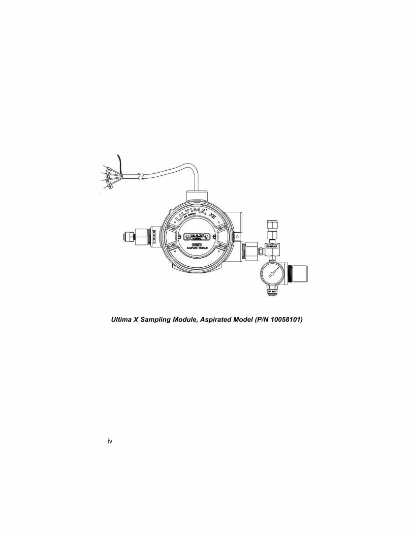
Ultima X Sampling Module, Aspirated Model (P/N 10058101)
iv
Table of Contents
Chapter 1, General Information . . . . . . . . . . . . . . . . . . . .1-1
Introduction . . . . . . . . . . . . . . . . . . . . . . . . . . . . . . . . . . .1-1
The Ultima X Sampling Module - Aspirated Model: . . .1-1
Unpacking Unit . . . . . . . . . . . . . . . . . . . . . . . . . . . . . .1-1
Figure 1-1. Sampling Module Installation . . . . . . . .1-2
Unit Identification . . . . . . . . . . . . . . . . . . . . . . . . . . . . .1-3
Figure 1-2. Identification Label . . . . . . . . . . . . . . . .1-3
Table 1-1. Performance Specifications for
Ultima X Sampling Module - Aspirated Model 1-4
Terminology . . . . . . . . . . . . . . . . . . . . . . . . . . . . . . . . .1-5
Chapter 2, Installation . . . . . . . . . . . . . . . . . . . . . . . . . . . .2-1
General . . . . . . . . . . . . . . . . . . . . . . . . . . . . . . . . . . . . . .2-1
" WARNING . . . . . . . . . . . . . . . . . . . . . . . . . . . . .2-1
Mounting the Aspirated Sampling Module Unit
(All Models) . . . . . . . . . . . . . . . . . . . . . . . . . . . . . . . . . .2-2
" CAUTION . . . . . . . . . . . . . . . . . . . . . . . . . . . . . .2-2
" CAUTION . . . . . . . . . . . . . . . . . . . . . . . . . . . . . .2-2
Sample Line Placement between Aspirated Sampling
Module and Ultima X Gas Monitor . . . . . . . . . . . . . . . . .2-3
" WARNING . . . . . . . . . . . . . . . . . . . . . . . . . . . . .2-3
Table 2-1. Parts List . . . . . . . . . . . . . . . . . . . . . . .2-3
Sample Line Placement . . . . . . . . . . . . . . . . . . . . . . . . .2-4
" CAUTION . . . . . . . . . . . . . . . . . . . . . . . . . . . . . .2-4
Figure 2-1. Three Ultima X Monitors &
a Sampling Module . . . . . . . . . . . . . . . . . . . .2-5
" CAUTION . . . . . . . . . . . . . . . . . . . . . . . . . . . . . .2-6
Exhaust Line Placement . . . . . . . . . . . . . . . . . . . . . . . . .2-7
Aspirator Connection . . . . . . . . . . . . . . . . . . . . . . . . . . .2-7
" WARNING . . . . . . . . . . . . . . . . . . . . . . . . . . . . .2-7
Electrical Connection . . . . . . . . . . . . . . . . . . . . . . . . . . .2-8
Figure 2-2. Typical Wiring . . . . . . . . . . . . . . . . . . . .2-8
Electrical Connection Procedure . . . . . . . . . . . . . . . . .2-8
" CAUTION . . . . . . . . . . . . . . . . . . . . . . . . . . . . . .2-8v
" WARNING . . . . . . . . . . . . . . . . . . . . . . . . . . . . .2-9
" WARNING . . . . . . . . . . . . . . . . . . . . . . . . . . . . .2-9
Table 2-2. Wiring Identification . . . . . . . . . . . . . . .2-10
Initial Start-Up . . . . . . . . . . . . . . . . . . . . . . . . . . . . . . . .2-10
" CAUTION . . . . . . . . . . . . . . . . . . . . . . . . . . . . .2-10
Chapter 3, Calibration and Operation . . . . . . . . . . . . . . .3-1
Introduction . . . . . . . . . . . . . . . . . . . . . . . . . . . . . . . . . . .3-1
Calibration Procedures . . . . . . . . . . . . . . . . . . . . . . . . . .3-2
Equipment Needed: . . . . . . . . . . . . . . . . . . . . . . . . . . .3-2
Zeroing the System with the
Ultima X Sampling Module . . . . . . . . . . . . . . . . . . . . .3-2
" WARNING . . . . . . . . . . . . . . . . . . . . . . . . . . . . .3-2
Spanning with the Ultima X Sampling Module . . . . . .3-3
Operation . . . . . . . . . . . . . . . . . . . . . . . . . . . . . . . . . . . .3-3
" WARNING . . . . . . . . . . . . . . . . . . . . . . . . . . . . .3-3
Chapter 4, Maintenance and Troubleshooting Guidelines . . . . . . . . . . . . .4-1
Maintenance . . . . . . . . . . . . . . . . . . . . . . . . . . . . . . . . . .4-1
Filter Maintenance . . . . . . . . . . . . . . . . . . . . . . . . . . . . .4-1
Troubleshooting Guidelines . . . . . . . . . . . . . . . . . . . . . .4-2
Table 4-1. Troubleshooting Guidelines . . . . . . . . . .4-2
Replacement Parts . . . . . . . . . . . . . . . . . . . . . . . . . . . . .4-3
Table 4-2. Parts List . . . . . . . . . . . . . . . . . . . . . . . .4-3
vi
1-1
Chapter 1, General Information
Introduction
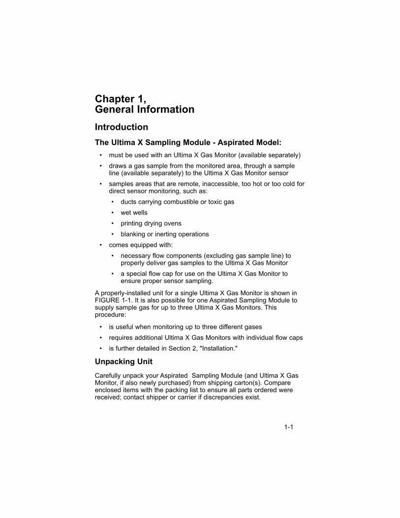
The Ultima X Sampling Module - Aspirated Model:
• must be used with an Ultima X Gas Monitor (available separately)
• draws a gas sample from the monitored area, through a sampleline (available separately) to the Ultima X Gas Monitor sensor
• samples areas that are remote, inaccessible, too hot or too cold fordirect sensor monitoring, such as:
• ducts carrying combustible or toxic gas
• wet wells
• printing drying ovens
• blanking or inerting operations
• comes equipped with:
• necessary flow components (excluding gas sample line) toproperly deliver gas samples to the Ultima X Gas Monitor
• a special flow cap for use on the Ultima X Gas Monitor toensure proper sensor sampling.
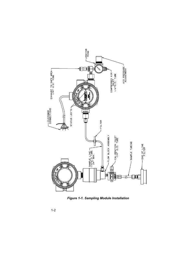
A properly-installed unit for a single Ultima X Gas Monitor is shown inFIGURE 1-1. It is also possible for one Aspirated Sampling Module tosupply sample gas for up to three Ultima X Gas Monitors. Thisprocedure:
• is useful when monitoring up to three different gases
• requires additional Ultima X Gas Monitors with individual flow caps
• is further detailed in Section 2, "Installation."
Unpacking Unit
Carefully unpack your Aspirated Sampling Module (and Ultima X GasMonitor, if also newly purchased) from shipping carton(s). Compareenclosed items with the packing list to ensure all parts ordered werereceived; contact shipper or carrier if discrepancies exist.
1-2
Figure 1-1. Sampling Module Installation
Each Aspirated Sampling Module package contains:
• Aspirated Sampling Module
• Flow cap for one Ultima X Gas Monitor
• Tubing and in-line Filter
• End-of-line Filter
• Instruction Manual
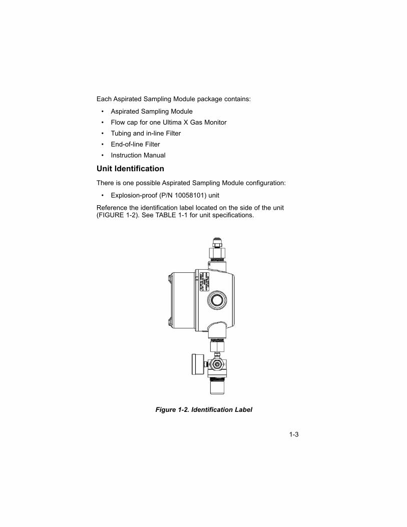
Unit Identification
There is one possible Aspirated Sampling Module configuration:
• Explosion-proof (P/N 10058101) unit
Reference the identification label located on the side of the unit(FIGURE 1-2). See TABLE 1-1 for unit specifications.
Figure 1-2. Identification Label
1-3
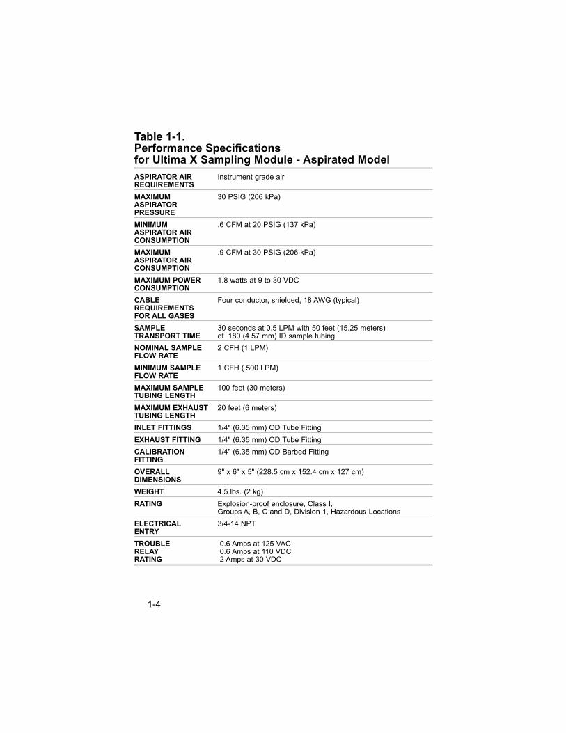
Table 1-1. Performance Specifications for Ultima X Sampling Module - Aspirated Model
ASPIRATOR AIR Instrument grade airREQUIREMENTS
MAXIMUM 30 PSIG (206 kPa)ASPIRATORPRESSURE
MINIMUM .6 CFM at 20 PSIG (137 kPa)ASPIRATOR AIRCONSUMPTION
MAXIMUM .9 CFM at 30 PSIG (206 kPa)ASPIRATOR AIRCONSUMPTION
MAXIMUM POWER 1.8 watts at 9 to 30 VDCCONSUMPTION
CABLE Four conductor, shielded, 18 AWG (typical)REQUIREMENTSFOR ALL GASES
SAMPLE 30 seconds at 0.5 LPM with 50 feet (15.25 meters) TRANSPORT TIME of .180 (4.57 mm) ID sample tubing
NOMINAL SAMPLE 2 CFH (1 LPM)FLOW RATE
MINIMUM SAMPLE 1 CFH (.500 LPM)FLOW RATE
MAXIMUM SAMPLE 100 feet (30 meters)TUBING LENGTH
MAXIMUM EXHAUST 20 feet (6 meters)TUBING LENGTH
INLET FITTINGS 1/4" (6.35 mm) OD Tube Fitting
EXHAUST FITTING 1/4" (6.35 mm) OD Tube Fitting
CALIBRATION 1/4" (6.35 mm) OD Barbed FittingFITTING
OVERALL 9" x 6" x 5" (228.5 cm x 152.4 cm x 127 cm)DIMENSIONS
WEIGHT 4.5 lbs. (2 kg)
RATING Explosion-proof enclosure, Class I,Groups A, B, C and D, Division 1, Hazardous Locations
ELECTRICAL 3/4-14 NPTENTRY
TROUBLE 0.6 Amps at 125 VAC RELAY 0.6 Amps at 110 VDCRATING 2 Amps at 30 VDC
1-4
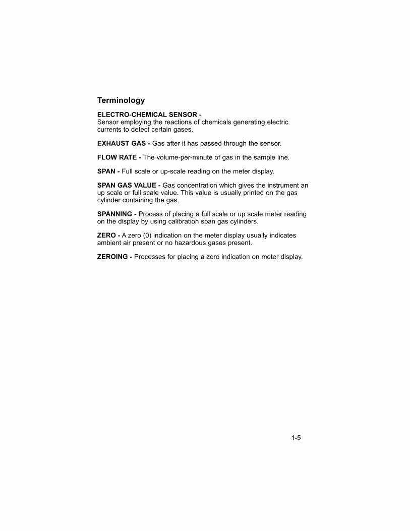
Terminology
ELECTRO-CHEMICAL SENSOR -Sensor employing the reactions of chemicals generating electriccurrents to detect certain gases.
EXHAUST GAS - Gas after it has passed through the sensor.
FLOW RATE - The volume-per-minute of gas in the sample line.
SPAN - Full scale or up-scale reading on the meter display.
SPAN GAS VALUE - Gas concentration which gives the instrument anup scale or full scale value. This value is usually printed on the gascylinder containing the gas.
SPANNING - Process of placing a full scale or up scale meter readingon the display by using calibration span gas cylinders.
ZERO - A zero (0) indication on the meter display usually indicatesambient air present or no hazardous gases present.
ZEROING - Processes for placing a zero indication on meter display.
1-5
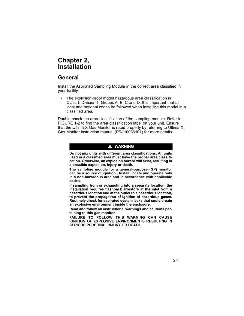
Chapter 2, Installation
General
Install the Aspirated Sampling Module in the correct area classified inyour facility.
• The explosion-proof model hazardous area classification is Class I, Division 1, Groups A, B, C and D. It is important that alllocal and national codes be followed when installing this model in aclassified area.
Double check the area classification of the sampling module. Refer toFIGURE 1-2 to find the area classification label on your unit. Ensurethat the Ultima X Gas Monitor is rated properly by referring to Ultima XGas Monitor instruction manual (P/N 10036101) for more details.
Do not mix units with different area classifications. All unitsused in a classified area must have the proper area classifi-cation. Otherwise, an explosion hazard will exist, resulting ina possible explosion, injury or death.
The sampling module for a general-purpose (GP) monitorcan be a source of ignition. Install, locate and operate onlyin a non-hazardous area and in accordance with applicablecodes.
If sampling from or exhausting into a separate location, theinstallation requires flashback arrestors at the inlet from ahazardous location and at the outlet to a hazardous location,to prevent the propagation of ignition of hazardous gases.Routinely check for aspirated system leaks that could createan explosive environment inside the enclosure.
Read and follow all instructions, warnings and cautions per-taining to this gas monitor.
FAILURE TO FOLLOW THIS WARNING CAN CAUSE IGNITION OF EXPLOSIVE ENVIRONMENTS RESULTING INSERIOUS PERSONAL INJURY OR DEATH.
" WARNING
2-1
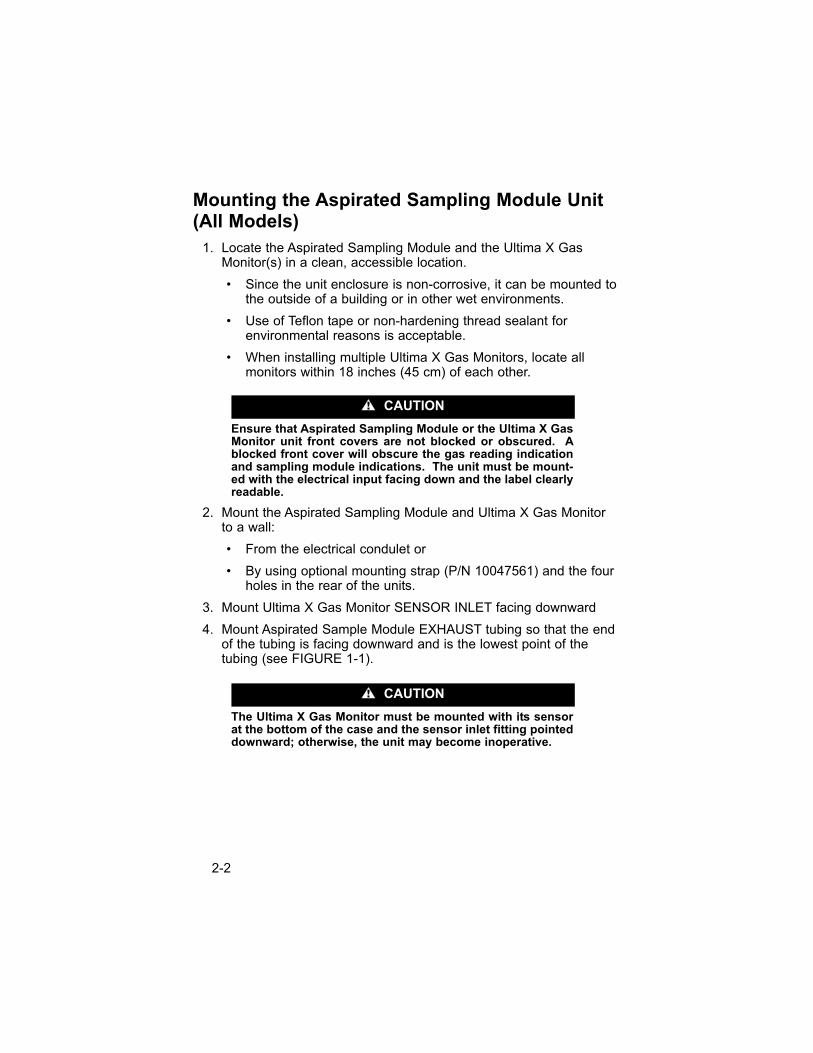
Mounting the Aspirated Sampling Module Unit (All Models)
1. Locate the Aspirated Sampling Module and the Ultima X GasMonitor(s) in a clean, accessible location.
• Since the unit enclosure is non-corrosive, it can be mounted tothe outside of a building or in other wet environments.
• Use of Teflon tape or non-hardening thread sealant forenvironmental reasons is acceptable.
• When installing multiple Ultima X Gas Monitors, locate allmonitors within 18 inches (45 cm) of each other.
Ensure that Aspirated Sampling Module or the Ultima X GasMonitor unit front covers are not blocked or obscured. Ablocked front cover will obscure the gas reading indicationand sampling module indications. The unit must be mount-ed with the electrical input facing down and the label clearlyreadable.
2. Mount the Aspirated Sampling Module and Ultima X Gas Monitor to a wall:
• From the electrical condulet or
• By using optional mounting strap (P/N 10047561) and the fourholes in the rear of the units.
3. Mount Ultima X Gas Monitor SENSOR INLET facing downward
4. Mount Aspirated Sample Module EXHAUST tubing so that the endof the tubing is facing downward and is the lowest point of thetubing (see FIGURE 1-1).
The Ultima X Gas Monitor must be mounted with its sensorat the bottom of the case and the sensor inlet fitting pointeddownward; otherwise, the unit may become inoperative.
" CAUTION
" CAUTION
2-2
Sample Line Placement between AspiratedSampling Module and Ultima X Gas Monitor
1. Remove all protective packaging plugs and/or caps from AspiratedSampling Module gas INLET and EXHAUST ports.
2. On new installations, skip to Step 4.
On existing installations of the Ultima X Gas Monitor: Remove theUltima X Gas Monitor(s) red plastic sensor cap and any gasketsremaining on the sensor. Do not remove the sensor element.
3. Locate the Aspirated Sampling Module flow block. Install the flowblock(s) on the Ultima X Gas Monitor(s) where the red plasticsensor cap was removed in the previous step. See FIGURE 1-1 and FIGURE 2-1.
• Additional flow blocks are available for additional Ultima X Gasmonitors.
• Refer to TABLE 2-1 for a description and part number foradditional flow blocks.
Install the proper flow block with the correct area classifica-tion for your additional Ultima Gas Monitors. Incorrect flowblocks will not enable the Ultima Gas Monitor to properlymonitor gas. Incorrect area classification will present anignition source, which may cause and explosion resulting ininjury or death.
Table 2-1. Parts List
ITEM PART NO.
Ultima XE Flow Block 10041866
Ultima XIR Flow Block 10042600
4. Attach the supplied tubing to the Aspirated Sampling Module portlabeled "TO ULTIMA X".
5. Attach the other end of the supplied tubing to the side of the flowblock (FIGURE 1-1).
• Tubing can be trimmed to ensure that there are no kinks.
" WARNING
2-3
The in-line filter must be used before the aspirated pump toprevent water entry from damaging unit.
• In-line filter (P/N 10051406) must be used somewhere alongthe tubing length. Ensure that the arrow on the in line filter ispointing towards the Aspirated Sampling Module.
• If installing additional Ultima X Gas Monitors, install tubingbetween units as shown in FIGURE 2-1. Use tubing compatiblewith the gas being sampled.
• MSA tubing is available (P/N 600771).
Sample Line Placement
The Aspirated Sampling Module draws a gas sample to the internally-mounted Ultima X Gas Monitor sensor.
• The Aspirated Sampling Module can be mounted up to 100 feet(30 meters) away from the monitored area.
• It uses 3/8-inch OD tubing to connect the Aspirated SamplingModule sample inlet to the end of the sample line in the monitoredarea. Tubing must be compatible with the sampled gas.
• It takes a maximum of 30 seconds for the sample gas to reach theAspirated Sampling Module when 50 feet (15.25 meters) of tubingis used:
• To decrease this time, shorten the sample line length.
• It is generally good practice to make the sample line as shortas possible.
• Depending on the gas characteristics, the end of the samplingtubing and the sample inlet should be mounted to best optimizesampling of that particular gas. Consult your architect, facilitymanager or safety engineer for guidance in proper placement ofthe sampling tube inlet.
• Testing for ventilation patterns is useful in establishing sample inletlocation. Smoke tubes (P/N 458481) are useful in measuring thedirection and rate of air flow to determine which areas to monitor.
• The particulate filter provided should be used at the sample end of the sample line to help prevent dirt and dust from cloggingthe sample line. This filter must be compatible with the gas being sampled.
" CAUTION
2-4
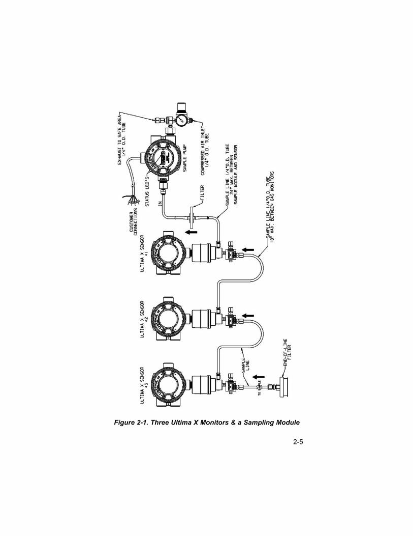
Figure 2-1. Three Ultima X Monitors & a Sampling Module
2-5
• It is recommended that a stainless steel of Teflon (Trademark ofthe DuPont Company) sample line be used for monitoring gasesthat are highly reactive such as:
• Nitrogen Dioxide
• Sulfur Dioxide
• Chlorine
• Chlorine Dioxide
• Hydrogen Chloride
• Ammonia
• Fluorine
• Bromine.
• Use an end-of-line filter (P/N 637921) with the above gases. The filter and sample line should be inspected periodically andreplaced if dirty.
All Ultima X Gas Monitors must be mounted in ambient,interference-free air; otherwise, erroneous readings mayresult.
Do not attempt to clean the sample line by applying com-pressed air.
1. Remove all protective packaging plugs and/or caps from theAspirated Sampling Module:
• gas inlet
• exhaust ports.
2. Attach a 1/4-inch (6.35 mm) OD sample tubing to the flow blocksample inlet fitting on the Ultima X Gas monitor (FIGURE 1-1).Ensure tubing is compatible with the sampled gas.
3. Route the sample tubing to the area to be monitored.
NOTE: Do not run the sample tubing in water or across areas ofvibration, doorways, man ways or access ways; otherwise,a sample tubing leak or tripping hazard may result.
4. Using suitable hardware (not supplied):
• fasten the sample tubing to supports
• fasten the end of the sample tubing and sample inlet in themonitoring area.
• The sample inlet should be pointed downward to preventdirt and water from entering the sample tubing line.
" CAUTION
2-6
5. Install the provided end-of-line filter at the end of the samplingtubing, if applicable.
6. Check for leaks along the entire length of the sample tubing line.Any leak will dilute the gas sample from the area of interest andgive a lower than actual gas reading.
Exhaust Line Placement
1. Attach a 1/4-inch (6.35 mm) OD sample tubing to the exhaustoutlet fitting on the Aspirated Sampling Module Unit.
2. Route the exhaust tubing into a safe area where the gas samplecan be vented. Avoid any sharp bends or elbows. Route the tubingto allow any collected water to drain.
• The maximum exhaust tubing length is 20 feet (6 meters).
NOTE: Do not run the exhaust tubing in water or across areas ofvibration or across doorways, man ways or access ways;otherwise, a leak in the exhaust tubing or a tripping hazardmay result.
3. Fasten the exhaust tubing to supports using suitable hardware (not supplied).
4. Fasten the end of the exhaust tubing in the area of interest byusing suitable hardware (not supplied)
• Exhaust inlet should be pointed downward to prevent dirt andwater from entering the exhaust tubing line.
NOTE: Exhaust to a safe or non-hazardous area only.
5. Check for leaks along entire length of the exhaust tubing line.
Aspirator Connection
Connect the Aspirated Sampling Module to compressed air via the 1/4"OD tube fitting at the top of the unit. The compressed air must beinstrument-grade quality. Maximum inlet air pressure must not exceed25 psig (172 kPa).
Connecting the Aspirated Sampling Module to an inferior-quality or an over-pressure air supply can cause incorrectgas readings or damage to the Sampling Module.
" WARNING
2-7
Electrical Connection
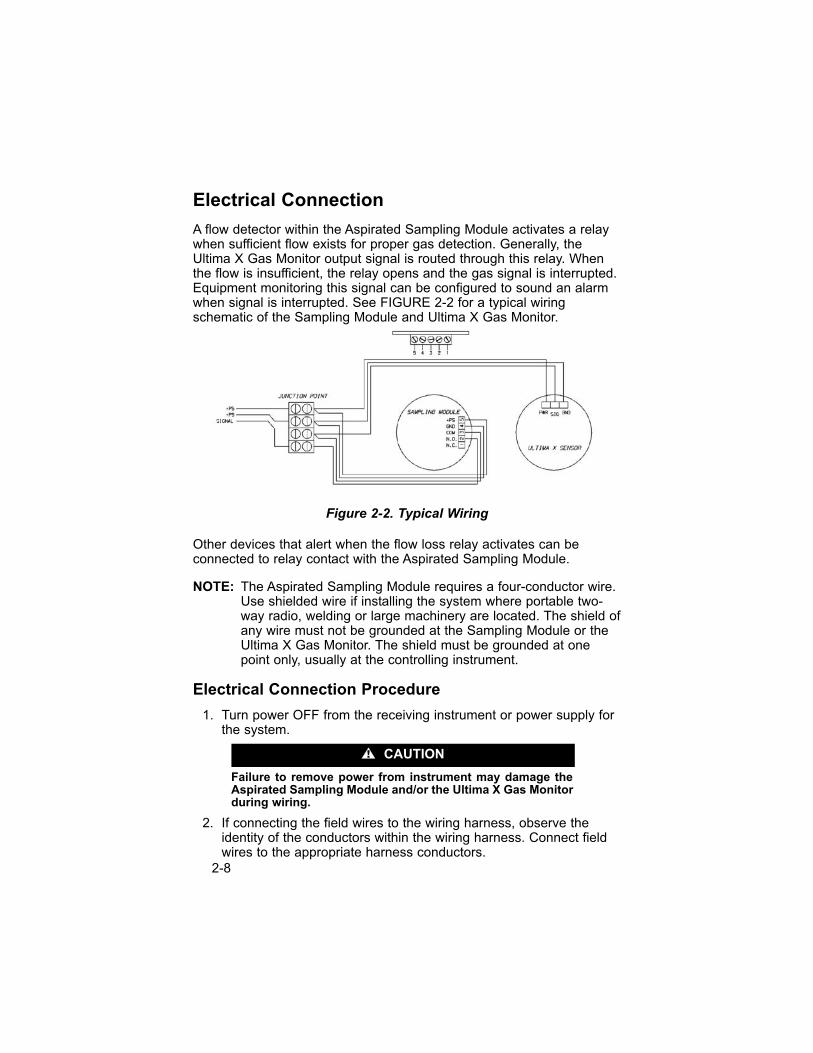
A flow detector within the Aspirated Sampling Module activates a relaywhen sufficient flow exists for proper gas detection. Generally, theUltima X Gas Monitor output signal is routed through this relay. Whenthe flow is insufficient, the relay opens and the gas signal is interrupted.Equipment monitoring this signal can be configured to sound an alarmwhen signal is interrupted. See FIGURE 2-2 for a typical wiringschematic of the Sampling Module and Ultima X Gas Monitor.
Other devices that alert when the flow loss relay activates can beconnected to relay contact with the Aspirated Sampling Module.
NOTE: The Aspirated Sampling Module requires a four-conductor wire.Use shielded wire if installing the system where portable two-way radio, welding or large machinery are located. The shield ofany wire must not be grounded at the Sampling Module or theUltima X Gas Monitor. The shield must be grounded at onepoint only, usually at the controlling instrument.
Electrical Connection Procedure
1. Turn power OFF from the receiving instrument or power supply forthe system.
Failure to remove power from instrument may damage theAspirated Sampling Module and/or the Ultima X Gas Monitorduring wiring.
2. If connecting the field wires to the wiring harness, observe theidentity of the conductors within the wiring harness. Connect fieldwires to the appropriate harness conductors.
" CAUTION
Figure 2-2. Typical Wiring
2-8
• If unit is an explosion-proof model:
• Remove and discard the cable grip threaded into the enclosure.
• Follow National Electrical and local procedural Codes.
3. If not using the attached wiring harness:
a. Remove the top cover of the Sampling Module by rotating thecover counter-clockwise.
Ensure that no flammable or combustible gas exists in theatmosphere by checking with a portable instrument capableof detecting combustible gases; otherwise, a spark maygenerate and cause an explosion, which may result in injuryor death.
Do not allow the lid to remain off of the explosion-proofAspirated Sampling Module. Flammable or combustible gasin the atmosphere may ignite a spark; that, in turn, maycause an explosion and result in injury or death.
b. Unscrew and remove the two top-cover screws.
c. Lift top cover to expose the wiring terminal strip on the bottomside of the cover.
d. Loosen terminal strip screws and remove wiring harness.
• If unit is an explosion-proof model:
• Remove and discard the wiring harness and cablegrip threaded into the enclosure
• Install a conduit seal into the enclosure.
e. Route a cable (not supplied) through the electrical entry of theAspirated Sampling Module.
f. Connect the conductors to the wiring terminal strip noting theidentity of the wires. See FIGURE 2-1 and TABLE 2-2.
g. Replace the top cover and tighten with the two screws.
h. Replace lid and tighten in place.
Do not allow lid to remain off of the explosion-proofAspirated Sampling Module. Flammable or combustible gasin the atmosphere may ignite a spark; that, in turn, maycause an explosion and result in injury or death.
" WARNING
" WARNING
2-9
Table 2-2. Wiring Identification
POSITION DESCRIPTION
1 Normally closed contact of the flow loss relay
2 Normally open contact of the flow loss relay
3 Common position of the flow loss relay
4 Ground or negative of the power supply
5 Positive or supply position of the power supply
4. Wire the other end of the wiring cable to your read-out instrumentand power supply, ensuring the cable from the Aspirated SamplingModule is wired to the proper connections on the instrument.Consult the instrument instruction manual for more wiring details.
Initial Start-Up
Before starting up the Aspirated Sampling Module:
1. Check wiring connections; see FIGURE 2-1 and TABLE 2-2.
2. Ensure that power supplied to the controlling instrument is theproper voltage with sufficient current capacity to operate theinstrument. Refer to the instrument instruction manual for properpower set-up.
3. Apply power to the instrument through a remote circuit breaker.
If relays in the controlling instrument are wired to externaldevices (e.g. horns, exhaust fans, and fire suppression sys-tems), these devices may activate while adjustments areperformed during the following procedures. Consult equip-ment instruction manual for further details. All instrumentsmust be returned to normal operation when AspiratedSampling Module and Ultima X Gas Monitor adjustments are completed.
4. Before applying compressed air to the Aspirated Sampling Modulecompressed air inlet:
a. Adjust the internal pressure regulator for 0 psig by pulling outthe red locking ring on the regulator and adjusting the knobfully counter-clockwise; see FIGURE 1-1.
b. Ensure the exhaust is not restricted.
" CAUTION
2-10
5. Apply the compressed air to the compressed air inlet of theAspirated Sampling Module at 20 to 25 psig (137 to 172 kPa).
6. Pull out the red locking ring and adjust the knob on the airregulator to obtain a reading of 10 psig (90 kPa).
7. Notice the low flow indication on the front panel:
• If low flow indication is not ON, push in the air regulator redlocking ring to lock the regulator at this pressure.
• If the low flow indication is still ON, increase air pressure byturning the knob until the indication turns OFF [do not exceed15 psig (100 kPa)]. When indication turns OFF, push in the redlocking ring of the air regulator.
• If the low flow indication is still ON at 15 psig (100 kPa),reduce the pressure below 10 psig (90 kPa) until the low flowindication turns OFF.
2-11
Chapter 3, Calibration and Operation
Introduction
Aspirated Sampling Module calibration uses the Ultima X Gas Monitorcalibration procedure. Refer to the Ultima X Gas Monitor instructionmanual and follow the procedure below:
Perform the calibration procedure regularly and maintain a log ofcalibration adjustments. Increase the frequency of calibration when anycalibration shows as much as 10% difference from the test gasconcentration. More frequent calibrations may be required when theAspirated Sampling Module is new or when the sensor is approachingits end of life. Also, perform the calibration procedure when installing orchanging the power source, sensor, or control instrumentation.
The necessary frequency of calibration depends on the operating timeand chemical exposures of the sensors. Newly installed units or newsensors should be calibrated more often until the calibration recordsprove sensor stability. The calibration frequency can then be reduced tothe schedule set by the safety officer or facility manager.
If this calibration procedure cannot be performed at any step, consultSection 4, "Troubleshooting Guidelines," localize the problem andreplace the inoperative component.
MSA offers periodic service that is available on a contract basis; formore information, please call MSA at 1-800-MSA-INST.
3-1
Calibration Procedures
Place the instrument receiving the signal from the Ultima X Gas Monitorinto CALIBRATION mode, if applicable.
It is necessary to put the receiving instrument in CALIBRA-TION mode. If the instrument is not in CALIBRATION mode,any alarm relays may energize and activate any safetydevices which are connected to the alarm relays of theinstrument.
Equipment Needed:
• Calibration Kit #40
• Appropriate ZERO and SPAN Gas Cylinders (refer to the Ultima X Instruction Manual (P/N 10036101).
• An Ultima X Controller (P/N 809086) or an Ultima X Calibrator (P/N 809997).
NOTE: If unsure of which SPAN gas to use or of the SPAN gas value, consult your safety engineer or officer orfacility manager.
1. Locate the ZERO gas cylinder and the appropriate regulator andtubing. Screw the regulator into the cylinder and connect the tubingto the regulator outlet. Ensure that tubing is compatible with thegas within the cylinder.
2. Before initiating the calibration procedures on the Ultima X GasMonitor, connect the tubing from the ZERO gas cylinder to theCalibration Inlet (See FIGURE 1-1).
Zeroing the System with the Ultima X Sampling Module
3. Initiate the calibration procedure on the Ultima X Gas Monitor; refer to the Ultima X Gas Monitor instruction manual.
4. When the Ultima X Gas Monitor displays "APPLY ZERO GAS",press and hold the button by the calibration inlet. Turn the knob on the regulator to permit the ZERO gas to flow. The Ultima X Gas Monitor will make all corrections to the zero signal; there areno adjustments necessary.
5. When the Ultima X Gas Monitor is done zeroing, close the cylindervalve, release the button by the calibration inlet, and quickly rotate
" WARNING
3-2
the zero gas cylinder to remove the ZERO gas cylinder. Do notremove the tubing from the flow controller.
6. Locate the SPAN gas cylinder and screw the regulator into the cylinder.
NOTE: If unsure of which SPAN gas to use or of the SPAN gasvalue, consult your safety engineer or officer or facilitymanager.
Spanning with the Ultima X Sampling Module
7. When calibrating, the SPAN immediately follows the ZERO; refer tothe Ultima X Calibrator or Controller instruction manual.
8. When the Ultima X Gas Monitor displays "APPLY SPAN GAS",press and hold the button by the calibration inlet. Turn the regulatorknob to permit the SPAN gas to flow. The Ultima X Gas Monitor will make all the correction to the span signal; there are noadjustments necessary.
9. When the Ultima X Gas Monitor calibration is complete, release thebutton by the calibration inlet, close the cylinder valve and removethe SPAN gas cylinder.
10.Unscrew the regulator from the gas cylinder and replace allcalibration components in the kit.
11.Return instrument receiving the signal from the Ultima X GasMonitor to the NORMAL run mode operation.
Operation
There are only two indicators on the front cover of the AspiratedSampling Module which affect the operation of the unit.
• The NORMAL (green LED) indicator, shows that there is sufficientsample flow (greater than .5 LPM).
• The LOW FLOW (red LED) indicator, when ON, indicates that the flow detector has found insufficient gas flow for propermonitoring. Refer to Section 4, "Troubleshooting Guidelines" for corrective action.
The pressure switch can fail and the orifice can clog if waterenters the system. Always use the proper in-line filter (P/N 10051406).
" WARNING
3-3
Chapter 4, Maintenance and TroubleshootingGuidelines
Maintenance
The Aspirated Sampling Module requires minimal maintenance.However, the filters need routine inspection and possible replacement. It is good practice to have on hand replacement filters to minimize anydown time of your unit (see TABLE 4-2).
Filter Maintenance
Filter maintenance consists of visual inspection of the two filters, end-of-line filter and the in-line filter which blocks water from enteringthe pump module. When new, filters are white; when loaded with dust ordirt, they normally turn dark in color. Visually inspect the two filtersperiodically. The frequency of this inspection depends on theenvironment; if the environment is extremely dirty or dusty, thisinspection should be done often.
End-of-line filters must be located so that they are not exposed toliquids or steam. If liquids become entrapped within a filter, replace thefilter as it will interfere with proper operation of the unit.
4-1
Troubleshooting Guidelines
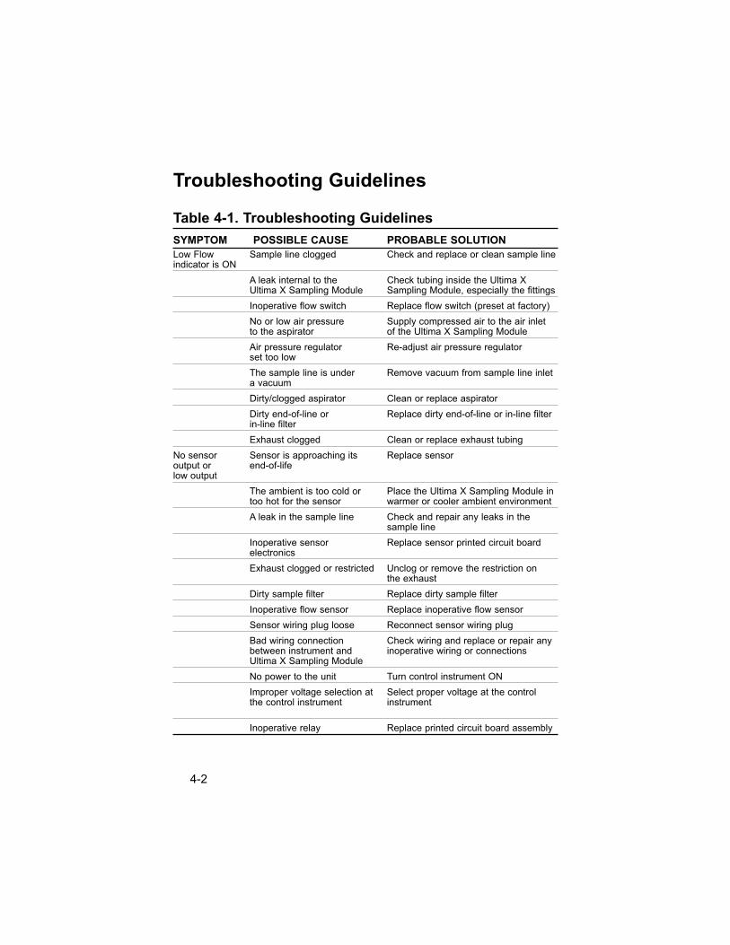
Table 4-1. Troubleshooting Guidelines
SYMPTOM POSSIBLE CAUSE PROBABLE SOLUTION
Low Flow Sample line clogged Check and replace or clean sample lineindicator is ON
A leak internal to the Check tubing inside the Ultima X Ultima X Sampling Module Sampling Module, especially the fittings
Inoperative flow switch Replace flow switch (preset at factory)
No or low air pressure Supply compressed air to the air inletto the aspirator of the Ultima X Sampling Module
Air pressure regulator Re-adjust air pressure regulatorset too low
The sample line is under Remove vacuum from sample line inleta vacuum
Dirty/clogged aspirator Clean or replace aspirator
Dirty end-of-line or Replace dirty end-of-line or in-line filterin-line filter
Exhaust clogged Clean or replace exhaust tubing
No sensor Sensor is approaching its Replace sensor output or end-of-lifelow output
The ambient is too cold or Place the Ultima X Sampling Module intoo hot for the sensor warmer or cooler ambient environment
A leak in the sample line Check and repair any leaks in the sample line
Inoperative sensor Replace sensor printed circuit boardelectronics
Exhaust clogged or restricted Unclog or remove the restriction on the exhaust
Dirty sample filter Replace dirty sample filter
Inoperative flow sensor Replace inoperative flow sensor
Sensor wiring plug loose Reconnect sensor wiring plug
Bad wiring connection Check wiring and replace or repair anybetween instrument and inoperative wiring or connectionsUltima X Sampling Module
No power to the unit Turn control instrument ON
Improper voltage selection at Select proper voltage at the controlthe control instrument instrument
Inoperative relay Replace printed circuit board assembly
4-2
Replacement Parts
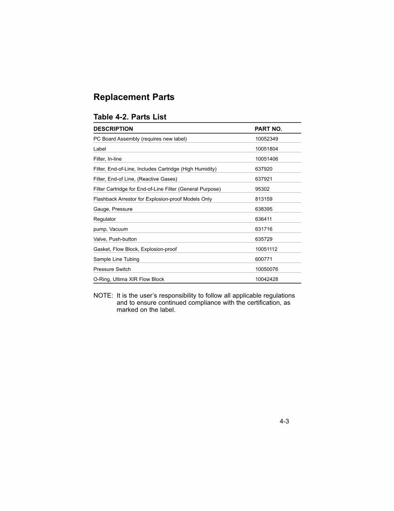
Table 4-2. Parts List
DESCRIPTION PART NO.
PC Board Assembly (requires new label) 10052349
Label 10051804
Filter, In-line 10051406
Filter, End-of-Line, Includes Cartridge (High Humidity) 637920
Filter, End-of Line, (Reactive Gases) 637921
Filter Cartridge for End-of-Line Filter (General Purpose) 95302
Flashback Arrestor for Explosion-proof Models Only 813159
Gauge, Pressure 638395
Regulator 636411
pump, Vacuum 631716
Valve, Push-button 635729
Gasket, Flow Block, Explosion-proof 10051112
Sample Line Tubing 600771
Pressure Switch 10050076
O-Ring, Ultima XIR Flow Block 10042428
NOTE: It is the user’s responsibility to follow all applicable regulationsand to ensure continued compliance with the certification, asmarked on the label.
4-3


![ULTIMA XL series / ULTIMA XT series - Heating and Process · PDF fileULTIMA XL® Series ULTIMA XT® Series Gas Monitors ... 5.2 ULTIMA XIR Cleaning Procedure ... General-purpose [GP]](https://img.pdfslide.us/doc/110x75/5aba02e37f8b9ab62f8e8c99/ultima-xl-series-ultima-xt-series-heating-and-process-xl-series-ultima-xt-series.jpg)