Embed Size (px)
DESCRIPTION
Flat-Plate PhotovoltaicModules and Panels
Citation preview

Docum
ent W
as D
ownlo
aded
By M
EI YAO W
ANG
For U
se B
y YFC
-BONEAGLE E
LECTRONIC T
ECHNOLOGY CO L
TD
25546 : 7/25/2007 -
8:25 P
M
UL COPYRIGHTED MATERIAL –NOT AUTHORIZED FOR FURTHER REPRODUCTION OR
DISTRIBUTION WITHOUT PERMISSION FROM UL
UL 1703
ISBN 0-7629-0760-6
Flat-Plate PhotovoltaicModules and Panels

Docum
ent W
as D
ownlo
aded
By M
EI YAO W
ANG
For U
se B
y YFC
-BONEAGLE E
LECTRONIC T
ECHNOLOGY CO L
TD
25546 : 7/25/2007 -
8:25 P
M
UL COPYRIGHTED MATERIAL –NOT AUTHORIZED FOR FURTHER REPRODUCTION OR
DISTRIBUTION WITHOUT PERMISSION FROM UL

Docum
ent W
as D
ownlo
aded
By M
EI YAO W
ANG
For U
se B
y YFC
-BONEAGLE E
LECTRONIC T
ECHNOLOGY CO L
TD
25546 : 7/25/2007 -
8:25 P
M
UL COPYRIGHTED MATERIAL –NOT AUTHORIZED FOR FURTHER REPRODUCTION OR
DISTRIBUTION WITHOUT PERMISSION FROM UL
Underwriters Laboratories Inc. (UL)333 Pfingsten RoadNorthbrook, IL 60062-2096
UL Standard for Safety for Flat-Plate Photovoltaic Modules and Panels, UL 1703
Third Edition, Dated March 15, 2002
Revisions: This Standard contains revisions through and including June 30, 2004.
SUMMARY OF TOPICS
The following revision is being issued to incorporate requirements in accordance with Subject1703 bulletin dated October 15, 2003.
Correction of test references in Table 18.1
UL Standards for Safety are developed and maintained in the Standard Generalized Markup Language(SGML). SGML -- an international standard (ISO 8879-1986) -- is a descriptive markup language thatdescribes a document’s structure and purpose, rather than its physical appearance on a page. Due toformatting differences resulting from the use of UL’s new electronic publishing system, please note thatadditional pages (on which no requirements have been changed) may be included in revision pages dueto relocation of existing text and reformatting of the Standard.
Text that has been changed in any manner is marked with a vertical line in the margin. Changes inrequirements are marked with a vertical line in the margin and are followed by an effective date noteindicating the date of publication or the date on which the changed requirement becomes effective.
The new and revised requirements are substantially in accordance with UL’s Bulletin(s) on this subjectdated October 15, 2003 and June 18, 2004.
As indicated on the title page (page 1), this UL Standard for Safety is an American National Standard.Attention is directed to the note on the title page of this Standard outlining the procedures to be followedto retain the approved text of this ANSI/UL Standard.
The UL Foreword is no longer located within the UL Standard. For information concerning the use andapplication of the requirements contained in this Standard, the current version of the UL Foreword islocated on ULStandardsInfoNet at: http://ulstandardsinfonet.ul.com/ulforeword.html
The master for this Standard at UL’s Northbrook Office is the official document insofar as it relates to aUL service and the compliance of a product with respect to the requirements for that product and service,or if there are questions regarding the accuracy of this Standard.
UL’s Standards for Safety are copyrighted by UL. Neither a printed copy of a Standard, nor the distributiondiskette for a Standard-on-Diskette and the file for the Standard on the distribution diskette should bealtered in any way. All of UL’s Standards and all copyrights, ownerships, and rights regarding thoseStandards shall remain the sole and exclusive property of UL.
All rights reserved. No part of this publication may be reproduced, stored in a retrieval system, ortransmitted in any form by any means, electronic, mechanical photocopying, recording, or otherwisewithout prior permission of UL.
JUNE 30, 2004 − UL 1703 tr1
Docum
ent W
as D
ownlo
aded
By M
EI YAO W
ANG
For U
se B
y YFC
-BONEAGLE E
LECTRONIC T
ECHNOLOGY CO L
TD
25546 : 7/25/2007 -
8:25 P
M
UL COPYRIGHTED MATERIAL –NOT AUTHORIZED FOR FURTHER REPRODUCTION OR
DISTRIBUTION WITHOUT PERMISSION FROM UL
Revisions of UL Standards for Safety are issued from time to time. A UL Standard for Safety is currentonly if it incorporates the most recently adopted revisions.
UL provides this Standard ″as is″ without warranty of any kind, either expressed or implied, including butnot limited to, the implied warranties of merchantability or fitness for any purpose.
In no event will UL be liable for any special, incidental, consequential, indirect or similar damages,including loss of profits, lost savings, loss of data, or any other damages arising out of the use of or theinability to use this Standard, even if UL or an authorized UL representative has been advised of thepossibility of such damage. In no event shall UL’s liability for any damage ever exceed the price paid forthis Standard, regardless of the form of the claim.
UL will attempt to answer support requests concerning electronic versions of its Standards. However, thissupport service is offered on a reasonable efforts basis only, and UL may not be able to resolve everysupport request. UL supports the electronic versions of its Standards only if they are used under theconditions and operating systems for which it is intended. UL’s support policies may change fromtime-to-time without notification.
UL reserves the right to change the format, presentation, file types and formats, delivery methods andformats, and the like of both its printed and electronic Standards without prior notice.
Purchasers of the electronic versions of UL’s Standards for Safety agree to defend, indemnify, and holdUL harmless from and against any loss, expense, liability, damage, claim, or judgement (includingreasonable attorney’s fees) resulting from any error or deviation introduced while purchaser is storing anelectronic Standard on the purchaser’s computer system.
If a single-user version electronic Standard was purchased, one copy of this Standard may be stored onthe hard disk of a single personal computer, or on a single LAN file-server or the permanent storagedevice of a multiple-user computer in such a manner that this Standard may only be accessed by one userat a time and for which there is no possibility of multiple concurrent access.
If a multiple-user version electronic Standard was purchased, one copy of the Standard may be stored ona single LAN file-server, or on the permanent storage device of a multiple-user computer, or on an Intranetserver. The number of concurrent users shall not exceed the number of users authorized.
Electronic Standards are intended for on-line use, such as for viewing the requirements of a Standard,conducting a word search, and the like. Only one copy of the Standard may be printed from eachsingle-user version of an electronic Standard. Only one copy of the Standard may be printed for eachauthorized user of a multiple-user version of an electronic Standard. Because of differences in thecomputer/software/printer setup used by UL and those of electronic Standards purchasers, the printedcopy obtained by a purchaser may not look exactly like the on-line screen view or the printed Standard.
An employee of an organization purchasing a UL Standard can make a copy of the page or pages beingviewed for their own fair and/or practical internal use.
The requirements in this Standard are now in effect, except for those paragraphs, sections, tables, figures,and/or other elements of the Standard having future effective dates as indicated in the note following theaffected item. The prior text for requirements that have been revised and that have a future effective dateare located after the Standard, and are preceded by a ″SUPERSEDED REQUIREMENTS″ notice.
New product submittals made prior to a specified future effective date will be judged under all of therequirements in this Standard including those requirements with a specified future effective date, unlessthe applicant specifically requests that the product be judged under the current requirements. However, if
JUNE 30, 2004 − UL 1703tr2

Docum
ent W
as D
ownlo
aded
By M
EI YAO W
ANG
For U
se B
y YFC
-BONEAGLE E
LECTRONIC T
ECHNOLOGY CO L
TD
25546 : 7/25/2007 -
8:25 P
M
UL COPYRIGHTED MATERIAL –NOT AUTHORIZED FOR FURTHER REPRODUCTION OR
DISTRIBUTION WITHOUT PERMISSION FROM UL
the applicant elects this option, it should be noted that compliance with all the requirements in thisStandard will be required as a condition of continued Listing and Follow-Up Services after the effectivedate, and understanding of this should be signified in writing.
Copyright © 2004 Underwriters Laboratories Inc.
This Standard consists of pages dated as shown in the following checklist:
Page Date
1-3 . . . . . . . . . . . . . . . . . . . . . . . . . . . . . . . . . . . . . . . . . . . . . . . . . . . . . . . . . . . . . . . . . . . . . . . . . . . . . June 30, 20044-5 . . . . . . . . . . . . . . . . . . . . . . . . . . . . . . . . . . . . . . . . . . . . . . . . . . . . . . . . . . . . . . . . . . . . . . . . . . . . March 15, 20026 . . . . . . . . . . . . . . . . . . . . . . . . . . . . . . . . . . . . . . . . . . . . . . . . . . . . . . . . . . . . . . . . . . . . . . . . . . . . . . . June 30, 20047 . . . . . . . . . . . . . . . . . . . . . . . . . . . . . . . . . . . . . . . . . . . . . . . . . . . . . . . . . . . . . . . . . . . . . . . . . . . . . October 1, 20038-11 . . . . . . . . . . . . . . . . . . . . . . . . . . . . . . . . . . . . . . . . . . . . . . . . . . . . . . . . . . . . . . . . . . . . . . . . . . . March 15, 200212 . . . . . . . . . . . . . . . . . . . . . . . . . . . . . . . . . . . . . . . . . . . . . . . . . . . . . . . . . . . . . . . . . . . . . . . . . . . . October 1, 200313-14 . . . . . . . . . . . . . . . . . . . . . . . . . . . . . . . . . . . . . . . . . . . . . . . . . . . . . . . . . . . . . . . . . . . . . . . . . . March 15, 200215-16 . . . . . . . . . . . . . . . . . . . . . . . . . . . . . . . . . . . . . . . . . . . . . . . . . . . . . . . . . . . . . . . . . . . . . . . . . October 1, 200317-19 . . . . . . . . . . . . . . . . . . . . . . . . . . . . . . . . . . . . . . . . . . . . . . . . . . . . . . . . . . . . . . . . . . . . . . . . . . March 15, 200220-23 . . . . . . . . . . . . . . . . . . . . . . . . . . . . . . . . . . . . . . . . . . . . . . . . . . . . . . . . . . . . . . . . . . . . . . . . . October 1, 200324-26 . . . . . . . . . . . . . . . . . . . . . . . . . . . . . . . . . . . . . . . . . . . . . . . . . . . . . . . . . . . . . . . . . . . . . . . . . . . June 30, 200427-28 . . . . . . . . . . . . . . . . . . . . . . . . . . . . . . . . . . . . . . . . . . . . . . . . . . . . . . . . . . . . . . . . . . . . . . . . . October 1, 200329-35 . . . . . . . . . . . . . . . . . . . . . . . . . . . . . . . . . . . . . . . . . . . . . . . . . . . . . . . . . . . . . . . . . . . . . . . . . . March 15, 200236-38B . . . . . . . . . . . . . . . . . . . . . . . . . . . . . . . . . . . . . . . . . . . . . . . . . . . . . . . . . . . . . . . . . . . . . . . . October 1, 200339-41 . . . . . . . . . . . . . . . . . . . . . . . . . . . . . . . . . . . . . . . . . . . . . . . . . . . . . . . . . . . . . . . . . . . . . . . . . . March 15, 200242-44 . . . . . . . . . . . . . . . . . . . . . . . . . . . . . . . . . . . . . . . . . . . . . . . . . . . . . . . . . . . . . . . . . . . . . . . . . October 1, 200345-46 . . . . . . . . . . . . . . . . . . . . . . . . . . . . . . . . . . . . . . . . . . . . . . . . . . . . . . . . . . . . . . . . . . . . . . . . . . March 15, 200247 . . . . . . . . . . . . . . . . . . . . . . . . . . . . . . . . . . . . . . . . . . . . . . . . . . . . . . . . . . . . . . . . . . . . . . . . . . . . October 1, 200348-68 . . . . . . . . . . . . . . . . . . . . . . . . . . . . . . . . . . . . . . . . . . . . . . . . . . . . . . . . . . . . . . . . . . . . . . . . . . March 15, 2002SA1-SA2. . . . . . . . . . . . . . . . . . . . . . . . . . . . . . . . . . . . . . . . . . . . . . . . . . . . . . . . . . . . . . . . . . . . . . . March 15, 2002A1-A2 . . . . . . . . . . . . . . . . . . . . . . . . . . . . . . . . . . . . . . . . . . . . . . . . . . . . . . . . . . . . . . . . . . . . . . . . . March 15, 2002CRG1-CRG4 . . . . . . . . . . . . . . . . . . . . . . . . . . . . . . . . . . . . . . . . . . . . . . . . . . . . . . . . . . . . . . . . . . . March 15, 2002
JUNE 30, 2004 − UL 1703 tr3

Docum
ent W
as D
ownlo
aded
By M
EI YAO W
ANG
For U
se B
y YFC
-BONEAGLE E
LECTRONIC T
ECHNOLOGY CO L
TD
25546 : 7/25/2007 -
8:25 P
M
UL COPYRIGHTED MATERIAL –NOT AUTHORIZED FOR FURTHER REPRODUCTION OR
DISTRIBUTION WITHOUT PERMISSION FROM UL
JUNE 30, 2004 − UL 1703tr4
No Text on This Page

Docum
ent W
as D
ownlo
aded
By M
EI YAO W
ANG
For U
se B
y YFC
-BONEAGLE E
LECTRONIC T
ECHNOLOGY CO L
TD
25546 : 7/25/2007 -
8:25 P
M
UL COPYRIGHTED MATERIAL –NOT AUTHORIZED FOR FURTHER REPRODUCTION OR
DISTRIBUTION WITHOUT PERMISSION FROM UL
MARCH 15, 2002(Title Page Reprinted: June 30, 2004)
1
UL 1703
Standard for Flat-Plate Photovoltaic Modules and Panels
First Edition – August, 1986Second Edition – May, 1993
Third Edition
March 15, 2002
The most recent designation of ANSI/UL 1703 as an American National Standard(ANSI) occurred on June 30, 2004. The ANSI approval does not include theCover Page, the Transmittal Pages, the Title Page, the Foreword or the CandianRequirements Comparison Guide (CRG).
This ANSI/UL Standard for Safety, which consists of the Third Edition withrevisions through June 30, 2004, is under continuous maintenance, wherebyeach revision is ANSI approved upon publication. Comments or proposals forrevisions on any part of the Standard may be submitted to UL at any time. Writtencomments are to be sent to the UL-Northbrook Standards Department, 333Pfingsten Road, Northbrook, IL 60062.
Revisions of this Standard will be made by issuing revised or additional pagesbearing their date of issue. A UL Standard is current only if it incorporates themost recently adopted revisions, all of which are itemized on the transmittal noticethat accompanies the latest set of revised requirements.
ISBN 0-7629-0760-6
COPYRIGHT © 1986, 2004 UNDERWRITERS LABORATORIES INC.
ANSI/UL 1703-2004

Docum
ent W
as D
ownlo
aded
By M
EI YAO W
ANG
For U
se B
y YFC
-BONEAGLE E
LECTRONIC T
ECHNOLOGY CO L
TD
25546 : 7/25/2007 -
8:25 P
M
UL COPYRIGHTED MATERIAL –NOT AUTHORIZED FOR FURTHER REPRODUCTION OR
DISTRIBUTION WITHOUT PERMISSION FROM UL
JUNE 30, 2004FLAT-PLATE PHOTOVOLTAIC MODULES AND PANELS - UL 17032
No Text on This Page

Docum
ent W
as D
ownlo
aded
By M
EI YAO W
ANG
For U
se B
y YFC
-BONEAGLE E
LECTRONIC T
ECHNOLOGY CO L
TD
25546 : 7/25/2007 -
8:25 P
M
UL COPYRIGHTED MATERIAL –NOT AUTHORIZED FOR FURTHER REPRODUCTION OR
DISTRIBUTION WITHOUT PERMISSION FROM UL
CONTENTS
INTRODUCTION
1 Scope . . . . . . . . . . . . . . . . . . . . . . . . . . . . . . . . . . . . . . . . . . . . . . . . . . . . . . . . . . . . . . . . . . . . . . . . . . . . . . .72 Glossary . . . . . . . . . . . . . . . . . . . . . . . . . . . . . . . . . . . . . . . . . . . . . . . . . . . . . . . . . . . . . . . . . . . . . . . . . . . . .83 Units of Measurement . . . . . . . . . . . . . . . . . . . . . . . . . . . . . . . . . . . . . . . . . . . . . . . . . . . . . . . . . . . . . . . . .94 Components . . . . . . . . . . . . . . . . . . . . . . . . . . . . . . . . . . . . . . . . . . . . . . . . . . . . . . . . . . . . . . . . . . . . . . . . . .95 References . . . . . . . . . . . . . . . . . . . . . . . . . . . . . . . . . . . . . . . . . . . . . . . . . . . . . . . . . . . . . . . . . . . . . . . . . .10
CONSTRUCTION
6 General . . . . . . . . . . . . . . . . . . . . . . . . . . . . . . . . . . . . . . . . . . . . . . . . . . . . . . . . . . . . . . . . . . . . . . . . . . . . .107 Polymeric Materials . . . . . . . . . . . . . . . . . . . . . . . . . . . . . . . . . . . . . . . . . . . . . . . . . . . . . . . . . . . . . . . . . .118 Current-Carrying Parts and Internal Wiring . . . . . . . . . . . . . . . . . . . . . . . . . . . . . . . . . . . . . . . . . . . . . .139 Wireways . . . . . . . . . . . . . . . . . . . . . . . . . . . . . . . . . . . . . . . . . . . . . . . . . . . . . . . . . . . . . . . . . . . . . . . . . . .1410 Connection Means . . . . . . . . . . . . . . . . . . . . . . . . . . . . . . . . . . . . . . . . . . . . . . . . . . . . . . . . . . . . . . . . . .1411 Bonding and Grounding . . . . . . . . . . . . . . . . . . . . . . . . . . . . . . . . . . . . . . . . . . . . . . . . . . . . . . . . . . . . .1512 Spacings . . . . . . . . . . . . . . . . . . . . . . . . . . . . . . . . . . . . . . . . . . . . . . . . . . . . . . . . . . . . . . . . . . . . . . . . . .1613 Wiring Compartments . . . . . . . . . . . . . . . . . . . . . . . . . . . . . . . . . . . . . . . . . . . . . . . . . . . . . . . . . . . . . . .17
13.1 General . . . . . . . . . . . . . . . . . . . . . . . . . . . . . . . . . . . . . . . . . . . . . . . . . . . . . . . . . . . . . . . . . . . . .1713.2 Metallic wiring compartments . . . . . . . . . . . . . . . . . . . . . . . . . . . . . . . . . . . . . . . . . . . . . . . . . .1813.3 Nonmetallic wiring compartments . . . . . . . . . . . . . . . . . . . . . . . . . . . . . . . . . . . . . . . . . . . . . . .19
14 Corrosion Resistance . . . . . . . . . . . . . . . . . . . . . . . . . . . . . . . . . . . . . . . . . . . . . . . . . . . . . . . . . . . . . . .2015 Accessibility of Uninsulated Live Parts . . . . . . . . . . . . . . . . . . . . . . . . . . . . . . . . . . . . . . . . . . . . . . . . .2116 Fire Resistance . . . . . . . . . . . . . . . . . . . . . . . . . . . . . . . . . . . . . . . . . . . . . . . . . . . . . . . . . . . . . . . . . . . . .2317 Superstrate . . . . . . . . . . . . . . . . . . . . . . . . . . . . . . . . . . . . . . . . . . . . . . . . . . . . . . . . . . . . . . . . . . . . . . . .23
PERFORMANCE
18 General . . . . . . . . . . . . . . . . . . . . . . . . . . . . . . . . . . . . . . . . . . . . . . . . . . . . . . . . . . . . . . . . . . . . . . . . . . . .2319 Temperature Test . . . . . . . . . . . . . . . . . . . . . . . . . . . . . . . . . . . . . . . . . . . . . . . . . . . . . . . . . . . . . . . . . . .2620 Voltage, Current and Power Measurements Test . . . . . . . . . . . . . . . . . . . . . . . . . . . . . . . . . . . . . . .3121 Leakage Current Test . . . . . . . . . . . . . . . . . . . . . . . . . . . . . . . . . . . . . . . . . . . . . . . . . . . . . . . . . . . . . . .3122 Strain Relief Test . . . . . . . . . . . . . . . . . . . . . . . . . . . . . . . . . . . . . . . . . . . . . . . . . . . . . . . . . . . . . . . . . . .3223 Push Test . . . . . . . . . . . . . . . . . . . . . . . . . . . . . . . . . . . . . . . . . . . . . . . . . . . . . . . . . . . . . . . . . . . . . . . . . .3224 Cut Test . . . . . . . . . . . . . . . . . . . . . . . . . . . . . . . . . . . . . . . . . . . . . . . . . . . . . . . . . . . . . . . . . . . . . . . . . . .3325 Bonding Path Resistance Test . . . . . . . . . . . . . . . . . . . . . . . . . . . . . . . . . . . . . . . . . . . . . . . . . . . . . . .3526 Dielectric Voltage-Withstand Test . . . . . . . . . . . . . . . . . . . . . . . . . . . . . . . . . . . . . . . . . . . . . . . . . . . . .3527 Wet Insulation-Resistance Test . . . . . . . . . . . . . . . . . . . . . . . . . . . . . . . . . . . . . . . . . . . . . . . . . . . . . . .3628 Reverse Current Overload Test . . . . . . . . . . . . . . . . . . . . . . . . . . . . . . . . . . . . . . . . . . . . . . . . . . . . . . .3729 Terminal Torque Test . . . . . . . . . . . . . . . . . . . . . . . . . . . . . . . . . . . . . . . . . . . . . . . . . . . . . . . . . . . . . . .3730 Impact Test . . . . . . . . . . . . . . . . . . . . . . . . . . . . . . . . . . . . . . . . . . . . . . . . . . . . . . . . . . . . . . . . . . . . . . . .3831 Fire Tests . . . . . . . . . . . . . . . . . . . . . . . . . . . . . . . . . . . . . . . . . . . . . . . . . . . . . . . . . . . . . . . . . . . . . . . . . .38
31.1 Spread-of-flame test . . . . . . . . . . . . . . . . . . . . . . . . . . . . . . . . . . . . . . . . . . . . . . . . . . . . . . . . . .3831.2 Burning-brand test . . . . . . . . . . . . . . . . . . . . . . . . . . . . . . . . . . . . . . . . . . . . . . . . . . . . . . . . . .38A
32 General . . . . . . . . . . . . . . . . . . . . . . . . . . . . . . . . . . . . . . . . . . . . . . . . . . . . . . . . . . . . . . . . . . . . . . . . . . . .3933 Water Spray Test . . . . . . . . . . . . . . . . . . . . . . . . . . . . . . . . . . . . . . . . . . . . . . . . . . . . . . . . . . . . . . . . . . .3934 Accelerated Aging Test . . . . . . . . . . . . . . . . . . . . . . . . . . . . . . . . . . . . . . . . . . . . . . . . . . . . . . . . . . . . . .4235 Temperature Cycling Test . . . . . . . . . . . . . . . . . . . . . . . . . . . . . . . . . . . . . . . . . . . . . . . . . . . . . . . . . . .43
JUNE 30, 2004 FLAT-PLATE PHOTOVOLTAIC MODULES AND PANELS - UL 1703 3

Docum
ent W
as D
ownlo
aded
By M
EI YAO W
ANG
For U
se B
y YFC
-BONEAGLE E
LECTRONIC T
ECHNOLOGY CO L
TD
25546 : 7/25/2007 -
8:25 P
M
UL COPYRIGHTED MATERIAL –NOT AUTHORIZED FOR FURTHER REPRODUCTION OR
DISTRIBUTION WITHOUT PERMISSION FROM UL
36 Humidity Test . . . . . . . . . . . . . . . . . . . . . . . . . . . . . . . . . . . . . . . . . . . . . . . . . . . . . . . . . . . . . . . . . . . . . .4537 Corrosive Atmosphere Test . . . . . . . . . . . . . . . . . . . . . . . . . . . . . . . . . . . . . . . . . . . . . . . . . . . . . . . . . .47
37.1 Salt spray test . . . . . . . . . . . . . . . . . . . . . . . . . . . . . . . . . . . . . . . . . . . . . . . . . . . . . . . . . . . . . . .4737.2 Moist carbon dioxide/sulphur dioxide . . . . . . . . . . . . . . . . . . . . . . . . . . . . . . . . . . . . . . . . . . . .48
38 Metallic Coating Thickness Test . . . . . . . . . . . . . . . . . . . . . . . . . . . . . . . . . . . . . . . . . . . . . . . . . . . . . .4939 Hot-Spot Endurance Test . . . . . . . . . . . . . . . . . . . . . . . . . . . . . . . . . . . . . . . . . . . . . . . . . . . . . . . . . . . .51
39.1 General . . . . . . . . . . . . . . . . . . . . . . . . . . . . . . . . . . . . . . . . . . . . . . . . . . . . . . . . . . . . . . . . . . . . .5139.2 Cell selection and instrumentation . . . . . . . . . . . . . . . . . . . . . . . . . . . . . . . . . . . . . . . . . . . . . .5139.3 Intrusive method . . . . . . . . . . . . . . . . . . . . . . . . . . . . . . . . . . . . . . . . . . . . . . . . . . . . . . . . . . . . .5239.4 Nonintrusive method . . . . . . . . . . . . . . . . . . . . . . . . . . . . . . . . . . . . . . . . . . . . . . . . . . . . . . . . . .5339.5 Theory and method of cell selection . . . . . . . . . . . . . . . . . . . . . . . . . . . . . . . . . . . . . . . . . . . .5439.6 Selection of hot-spot test level . . . . . . . . . . . . . . . . . . . . . . . . . . . . . . . . . . . . . . . . . . . . . . . . .5539.7 Type A cells (high shunt resistance) . . . . . . . . . . . . . . . . . . . . . . . . . . . . . . . . . . . . . . . . . . . .5639.8 Type B cells (low shunt resistance) . . . . . . . . . . . . . . . . . . . . . . . . . . . . . . . . . . . . . . . . . . . . .5639.9 Test execution . . . . . . . . . . . . . . . . . . . . . . . . . . . . . . . . . . . . . . . . . . . . . . . . . . . . . . . . . . . . . . .56
40 Arcing Test . . . . . . . . . . . . . . . . . . . . . . . . . . . . . . . . . . . . . . . . . . . . . . . . . . . . . . . . . . . . . . . . . . . . . . . .5840.1 General . . . . . . . . . . . . . . . . . . . . . . . . . . . . . . . . . . . . . . . . . . . . . . . . . . . . . . . . . . . . . . . . . . . . .5840.2 Method A . . . . . . . . . . . . . . . . . . . . . . . . . . . . . . . . . . . . . . . . . . . . . . . . . . . . . . . . . . . . . . . . . . .6040.3 Method B . . . . . . . . . . . . . . . . . . . . . . . . . . . . . . . . . . . . . . . . . . . . . . . . . . . . . . . . . . . . . . . . . . .6040.4 Methods A and B . . . . . . . . . . . . . . . . . . . . . . . . . . . . . . . . . . . . . . . . . . . . . . . . . . . . . . . . . . . .6040.5 Method C . . . . . . . . . . . . . . . . . . . . . . . . . . . . . . . . . . . . . . . . . . . . . . . . . . . . . . . . . . . . . . . . . . .6040.6 All methods . . . . . . . . . . . . . . . . . . . . . . . . . . . . . . . . . . . . . . . . . . . . . . . . . . . . . . . . . . . . . . . . . .61
41 Mechanical Loading Test . . . . . . . . . . . . . . . . . . . . . . . . . . . . . . . . . . . . . . . . . . . . . . . . . . . . . . . . . . . .6142 Wiring Compartment Securement Test . . . . . . . . . . . . . . . . . . . . . . . . . . . . . . . . . . . . . . . . . . . . . . . .63
PRODUCTION LINE TESTS
43 Factory Dielectric Voltage-Withstand Test . . . . . . . . . . . . . . . . . . . . . . . . . . . . . . . . . . . . . . . . . . . . . .6344 Factory Voltage, Current, and Power Measurements Test . . . . . . . . . . . . . . . . . . . . . . . . . . . . . . .6445 Grounding Continuity Test . . . . . . . . . . . . . . . . . . . . . . . . . . . . . . . . . . . . . . . . . . . . . . . . . . . . . . . . . . .64
RATING
46 Details . . . . . . . . . . . . . . . . . . . . . . . . . . . . . . . . . . . . . . . . . . . . . . . . . . . . . . . . . . . . . . . . . . . . . . . . . . . . .64
MARKING
47 Details . . . . . . . . . . . . . . . . . . . . . . . . . . . . . . . . . . . . . . . . . . . . . . . . . . . . . . . . . . . . . . . . . . . . . . . . . . . . .6548 Installation and Assembly Instructions . . . . . . . . . . . . . . . . . . . . . . . . . . . . . . . . . . . . . . . . . . . . . . . . .67
SUPPLEMENT SA - SAMPLE PRODUCTION LINE TESTS
SA1 Scope . . . . . . . . . . . . . . . . . . . . . . . . . . . . . . . . . . . . . . . . . . . . . . . . . . . . . . . . . . . . . . . . . . . . . . . . . .SA1SA2 Sample Size . . . . . . . . . . . . . . . . . . . . . . . . . . . . . . . . . . . . . . . . . . . . . . . . . . . . . . . . . . . . . . . . . . . .SA1SA3 Factory Voltage, Current, and Power Measurements Test . . . . . . . . . . . . . . . . . . . . . . . . . . . .SA1
APPENDIX A
Standards for Components. . . . . . . . . . . . . . . . . . . . . . . . . . . . . . . . . . . . . . . . . . . . . . . . . . . . . . . . . . . . . . A1
MARCH 15, 2002FLAT-PLATE PHOTOVOLTAIC MODULES AND PANELS - UL 17034

Docum
ent W
as D
ownlo
aded
By M
EI YAO W
ANG
For U
se B
y YFC
-BONEAGLE E
LECTRONIC T
ECHNOLOGY CO L
TD
25546 : 7/25/2007 -
8:25 P
M
UL COPYRIGHTED MATERIAL –NOT AUTHORIZED FOR FURTHER REPRODUCTION OR
DISTRIBUTION WITHOUT PERMISSION FROM UL
CANADIAN REQUIREMENTS COMPARISON GUIDE, CRG 1703
UL AND CANADIAN STANDARDS FOR FLAT-PLATE PHOTOVOLTAIC MODULES ANDPANELS . . . . . . . . . . . . . . . . . . . . . . . . . . . . . . . . . . . . . . . . . . . . . . . . . . . . . . . . . . . . . . . . . . . . . . . .CRG1
MARCH 15, 2002 FLAT-PLATE PHOTOVOLTAIC MODULES AND PANELS - UL 1703 5

Docum
ent W
as D
ownlo
aded
By M
EI YAO W
ANG
For U
se B
y YFC
-BONEAGLE E
LECTRONIC T
ECHNOLOGY CO L
TD
25546 : 7/25/2007 -
8:25 P
M
UL COPYRIGHTED MATERIAL –NOT AUTHORIZED FOR FURTHER REPRODUCTION OR
DISTRIBUTION WITHOUT PERMISSION FROM UL
This page intentionally left blank.
JUNE 30, 2004FLAT-PLATE PHOTOVOLTAIC MODULES AND PANELS - UL 17036

Docum
ent W
as D
ownlo
aded
By M
EI YAO W
ANG
For U
se B
y YFC
-BONEAGLE E
LECTRONIC T
ECHNOLOGY CO L
TD
25546 : 7/25/2007 -
8:25 P
M
UL COPYRIGHTED MATERIAL –NOT AUTHORIZED FOR FURTHER REPRODUCTION OR
DISTRIBUTION WITHOUT PERMISSION FROM UL
INTRODUCTION
1 Scope
1.1 These requirements cover flat-plate photovoltaic modules and panels intended for installation on orintegral with buildings, or to be freestanding (that is, not attached to buildings), in accordance with theNational Electrical Code, NFPA 70, and Model Building Codes.
1.2 These requirements cover modules and panels intended for use in systems with a maximum systemvoltage of 1000 V or less.
1.3 These requirements also cover components intended to provide electrical connection to and mountingfacilities for flat-plate photovoltaic modules and panels.
1.4 These requirements do not cover:
a) Equipment intended to accept the electrical output from the array, such as powerconditioning units (inverters) and batteries;
b) Any tracking mechanism;
c) Cell assemblies intended to operate under concentrated sunlight;
d) Optical concentrators; or
e) Combination photovoltaic-thermal modules or panels.
1.5 Deleted October 1, 2003
OCTOBER 1, 2003 FLAT-PLATE PHOTOVOLTAIC MODULES AND PANELS - UL 1703 7

Docum
ent W
as D
ownlo
aded
By M
EI YAO W
ANG
For U
se B
y YFC
-BONEAGLE E
LECTRONIC T
ECHNOLOGY CO L
TD
25546 : 7/25/2007 -
8:25 P
M
UL COPYRIGHTED MATERIAL –NOT AUTHORIZED FOR FURTHER REPRODUCTION OR
DISTRIBUTION WITHOUT PERMISSION FROM UL
2 Glossary
2.1 For the purpose of this standard, the following definitions apply.
2.2 AIR MASS (AM) – A dimensionless quantity, the ratio of:
a) The actual path length of radiation through the atmosphere to
b) The vertical path length of radiation through the atmosphere to sea level. At sea level, for allbut very high zenith angles (θz) (the angle subtended by the zenith and the line of sight to thesun),
AM = sec θz
2.3 ARRAY – A mechanically-integrated assembly of modules or panels with a support structure andfoundation, tracking, thermal control, and other components, if used, to form a dc power-producing unit.
2.4 BLOCKING DIODE – A diode used to block reverse current into a photovoltaic-source circuit.
2.5 BYPASS DIODE – A diode connected across one or more cells, modules, or panels in the forwardcurrent direction to allow current to bypass such cells, modules, or panels.
2.6 CELL – The basic photovoltaic device that generates electricity when exposed to sunlight.
2.7 ELECTRIC SHOCK – A risk of electric shock is considered to exist at a part if the potentialbetween the part and earth ground or any other accessible part is more than 30 Vdc and the leakagecurrent exceeds the values specified in Table 21.1.
2.8 ENCAPSULANT – Transparent insulating material enclosing the cells and cell interconnects.
2.9 INTERCONNECT – A conductor within a module that provides a mechanism for conductingelectricity between cells.
2.10 MAXIMUM POWER (Pmax) – The point on the current-versus-voltage curve of a module, at STC,where the product of current and voltage is maximum.
2.11 MAXIMUM SYSTEM VOLTAGE – The sum of the maximum open-circuit voltages of the maximumnumber of modules or panels to be connected in series in a system.
2.12 METALLIZATION – An electrically conductive metal coating on the surface of a cell.
2.13 MODULE (FLAT-PLATE) – The smallest environmentally protected, essentially planar assembly ofsolar cells and ancillary parts, such as interconnects and terminals, intended to generate dc powerunder unconcentrated sunlight. The structural (load-carrying) member of a module can either be the toplayer (superstrate), or the back layer (substrate), in which:
a) The superstrate is the transparent material forming the top (light-facing) outer surface of themodule. If load-carrying, this constitutes a structural superstrate.
b) The substrate is the material forming the back outer surface of a module. If load-carrying,this constitutes a structural substrate.
MARCH 15, 2002FLAT-PLATE PHOTOVOLTAIC MODULES AND PANELS - UL 17038
Docum
ent W
as D
ownlo
aded
By M
EI YAO W
ANG
For U
se B
y YFC
-BONEAGLE E
LECTRONIC T
ECHNOLOGY CO L
TD
25546 : 7/25/2007 -
8:25 P
M
UL COPYRIGHTED MATERIAL –NOT AUTHORIZED FOR FURTHER REPRODUCTION OR
DISTRIBUTION WITHOUT PERMISSION FROM UL
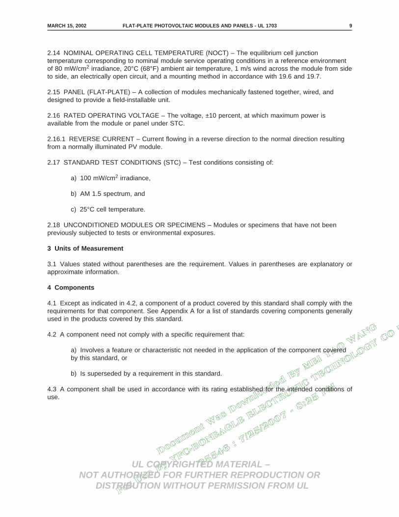
2.14 NOMINAL OPERATING CELL TEMPERATURE (NOCT) – The equilibrium cell junctiontemperature corresponding to nominal module service operating conditions in a reference environmentof 80 mW/cm2 irradiance, 20°C (68°F) ambient air temperature, 1 m/s wind across the module from sideto side, an electrically open circuit, and a mounting method in accordance with 19.6 and 19.7.
2.15 PANEL (FLAT-PLATE) – A collection of modules mechanically fastened together, wired, anddesigned to provide a field-installable unit.
2.16 RATED OPERATING VOLTAGE – The voltage, ±10 percent, at which maximum power isavailable from the module or panel under STC.
2.16.1 REVERSE CURRENT – Current flowing in a reverse direction to the normal direction resultingfrom a normally illuminated PV module.
2.17 STANDARD TEST CONDITIONS (STC) – Test conditions consisting of:
a) 100 mW/cm2 irradiance,
b) AM 1.5 spectrum, and
c) 25°C cell temperature.
2.18 UNCONDITIONED MODULES OR SPECIMENS – Modules or specimens that have not beenpreviously subjected to tests or environmental exposures.
3 Units of Measurement
3.1 Values stated without parentheses are the requirement. Values in parentheses are explanatory orapproximate information.
4 Components
4.1 Except as indicated in 4.2, a component of a product covered by this standard shall comply with therequirements for that component. See Appendix A for a list of standards covering components generallyused in the products covered by this standard.
4.2 A component need not comply with a specific requirement that:
a) Involves a feature or characteristic not needed in the application of the component coveredby this standard, or
b) Is superseded by a requirement in this standard.
4.3 A component shall be used in accordance with its rating established for the intended conditions ofuse.
MARCH 15, 2002 FLAT-PLATE PHOTOVOLTAIC MODULES AND PANELS - UL 1703 9

Docum
ent W
as D
ownlo
aded
By M
EI YAO W
ANG
For U
se B
y YFC
-BONEAGLE E
LECTRONIC T
ECHNOLOGY CO L
TD
25546 : 7/25/2007 -
8:25 P
M
UL COPYRIGHTED MATERIAL –NOT AUTHORIZED FOR FURTHER REPRODUCTION OR
DISTRIBUTION WITHOUT PERMISSION FROM UL
4.4 Specific components are incomplete in construction features or restricted in performance capabilities.Such components are intended for use only under limited conditions, such as certain temperatures notexceeding specified limits, and shall be used only under those specific conditions.
5 References
5.1 Any undated reference to a code or standard appearing in the requirements of this standard shall beinterpreted as referring to the latest edition of that code or standard.
CONSTRUCTION
6 General
6.1 A module shall be completely assembled when shipped from the factory. A panel may be completelyassembled when shipped from the factory, or may be provided in subassemblies, provided assembly ofthe panel does not involve any action that is likely to affect compliance with the requirements of thisstandard.
Exception: An assembly part need not be affixed to the module at the factory.
6.2 A module or panel assembly bolt, screw, or other part shall not be intended for securing the completedevice to the supporting surface or frame.
6.3 Incorporation of a module or panel into the final assembly shall not require any alteration of themodule or panel unless specific details describing necessary modification(s) for alternate installation(s)are provided in the installation instructions. If a module or panel must bear a definite relationship toanother for the intended installation and operation of the array (for example, to allow connectors to mate),it shall be constructed to permit it to be incorporated into the array in the correct relationship without theneed for alteration.
6.4 The construction of a product shall be such that during installation it will not be necessary to alter orremove any cover, baffle, insulation, or shield that is required to reduce the likelihood of:
a) Excessive temperatures, or
b) Unintentional contact with a part that may involve a risk of electric shock.
Exception: A cover of a wiring compartment providing access to a connection means that may involve arisk of electric shock may be removable to allow for the making of electrical connections.
6.5 Parts shall be prevented from loosening or turning if such loosening or turning may result in a risk offire, electric shock, or injury to persons.
6.6 Friction between surfaces is not acceptable as the sole means to inhibit the turning or loosening of apart, but a lock washer properly applied is acceptable for this purpose.
MARCH 15, 2002FLAT-PLATE PHOTOVOLTAIC MODULES AND PANELS - UL 170310

Docum
ent W
as D
ownlo
aded
By M
EI YAO W
ANG
For U
se B
y YFC
-BONEAGLE E
LECTRONIC T
ECHNOLOGY CO L
TD
25546 : 7/25/2007 -
8:25 P
M
UL COPYRIGHTED MATERIAL –NOT AUTHORIZED FOR FURTHER REPRODUCTION OR
DISTRIBUTION WITHOUT PERMISSION FROM UL
6.7 An adjustable or movable structural part shall be provided with a locking device to reduce thelikelihood of unintentional shifting, if any such shifting may result in a risk of fire, electric shock, or injuryto persons.
6.8 Metals used in locations that may be wet or moist shall not be employed in combinations that couldresult in deterioration of either metal such that the product would not comply with the requirements in thisstandard.
6.9 Edges, projections, and corners of photovoltaic modules and panels shall be such as to reduce therisk of injury to persons.
6.10 Whenever a referee measurement is necessary to determine that a part as mentioned in 6.9 is notsufficiently sharp to constitute a risk of injury to persons, the method described in the requirements in theStandard for Determination of Sharpness of Edges on Equipment, UL 1439, is to be employed.
7 Polymeric Materials
7.1 A polymeric material system serving as the enclosure of a part involving a risk of fire or electric shockshall comply with the applicable requirements in the Standard for Polymeric Materials – Use in ElectricalEquipment Evaluations, UL 746C, concerning:
a) Flammability,
b) Ultraviolet light exposure,
c) Water exposure and immersion, and
d) Hot-wire ignition (HWI).
Exception: The flammability tests prescribed in UL 746C do not apply to the superstrate, encapsulation,and substrate. These materials shall comply with 7.4.
7.2 A polymeric material system serving as the support or insulation of a part involving a risk of fire orelectric shock shall:
a) Have a flammability classification of HB, V-2, V-1, or V-0 determined in accordance with theStandard for Tests for Flammability of Plastic Materials for Parts in Devices and Appliances, UL94;
b) Have a minimum High-Current Arc Ignition performance level category (PLC) in accordancewith the following:
MARCH 15, 2002 FLAT-PLATE PHOTOVOLTAIC MODULES AND PANELS - UL 1703 11

Docum
ent W
as D
ownlo
aded
By M
EI YAO W
ANG
For U
se B
y YFC
-BONEAGLE E
LECTRONIC T
ECHNOLOGY CO L
TD
25546 : 7/25/2007 -
8:25 P
M
UL COPYRIGHTED MATERIAL –NOT AUTHORIZED FOR FURTHER REPRODUCTION OR
DISTRIBUTION WITHOUT PERMISSION FROM UL
Flammability classification High-current arc ignition, PLC
HB 1
V-2 2
V-1 2
V-0 3
c) Have a Comparative Tracking Index performance level category (PLC) of 2 or better, whenthe system voltage rating is 600 V or less, as determined in accordance with the Standard forPolymeric Materials – Short Term Property Evaluations, UL 746A;
d) Have an Inclined Plane Tracking (ASTM D2303) rating of 1 h using the time to track methodat 2.5 kilovolts when the system voltage rating is in the range 601 – 1000 V; and
e) Comply with the requirements for exposure to ultraviolet light as determined in accordancewith the Standard for Polymeric Materials – Use in Electrical Equipment Evaluations, UL 746C,when exposed to light during normal operation of the product. Polymeric materials that areexposed to sunlight and are protected by glass, or other transparent medium, shall be testedwith an equivalent layer of that medium attenuating the ultraviolet light exposure during the test.
Exception: Encapsulant materials between the substrate and the superstrate are not required to complywith this requirement.
7.3 A polymeric substrate or superstrate shall have a thermal index, both electrical and mechanical, asdetermined in accordance with the Standard for Polymeric Materials – Long Term Property Evaluations,UL 746B, not less than 90°C (194°F). In addition, the thermal index shall not be less than 20°C (36°F)above the measured operating temperature of the material. All other polymeric materials shall have athermal index (electrical and mechanical) 20°C above the measured operating temperature. Themeasured operating temperature is the temperature measured during the open-circuit mode forTemperature Test, Section 19, or the temperature during the short-circuit mode, whichever is greater.
7.4 A polymeric material that serves as the outer enclosure for a module or panel that:
a) is intended to be installed in a multi-module or multi-panel system; or
b) has an exposed surface area greater than 10 ft2(0.93 m2) or a single dimension larger than6 ft (1.83 m)
shall have a flame spread index of 100 or less as determined under the Standard Method of Test forSurface Flammability of Materials Using a Radiant Heat Energy Source, ASTM E162-2001.
Exception No. 1: A material that serves as the outer enclosure for a small cover or box used for electricalconnections is not required to have an index of 100 or less.
Exception No. 2: A material that serves as the outer enclosure for a module or panel complying with 16.1meets the intent of this requirement.
7.4 revised October 1, 2003
OCTOBER 1, 2003FLAT-PLATE PHOTOVOLTAIC MODULES AND PANELS - UL 170312
Docum
ent W
as D
ownlo
aded
By M
EI YAO W
ANG
For U
se B
y YFC
-BONEAGLE E
LECTRONIC T
ECHNOLOGY CO L
TD
25546 : 7/25/2007 -
8:25 P
M
UL COPYRIGHTED MATERIAL –NOT AUTHORIZED FOR FURTHER REPRODUCTION OR
DISTRIBUTION WITHOUT PERMISSION FROM UL
7.5 A barrier or liner of polymeric insulating material providing the sole insulation between a live part andan accessible metal part or between uninsulated live parts not of the same potential shall be of adequatethickness and of a material appropriate for the application. The barrier or liner shall be held in place andshall not be adversely affected to the extent that its necessary properties may fall below the minimumacceptable values for the application.
8 Current-Carrying Parts and Internal Wiring
8.1 A current-carrying part and wiring shall have the mechanical strength and ampacity necessary for theservice.
8.2 A current-carrying part shall be of silver, a copper-base alloy, stainless steel, aluminum, or othermaterial appropriate for the application.
8.3 Wiring used in a module or panel shall be insulated and acceptable for the purpose, when consideredwith respect to temperature, voltage, and the conditions of service to which the wiring is likely to besubjected within the equipment.
8.4 A splice shall be provided with insulation equivalent to that required for the wires involved.
8.5 A joint or connection shall be mechanically secure and shall provide electrical contact without strainon connections and terminals. Soldered connections between interconnects and metallizations areconsidered mechanically secure when held by encapsulation systems.
8.6 An uninsulated live part, including a terminal, shall be secured to its supporting surface by a methodother than friction between surfaces so that it will be prevented from turning or shifting in position if suchmotion may result in reduction of spacings to less than required in Tables 12.1 and 12.2.
8.7 Strain relief shall be provided so that stress on a lead intended for field connection, or otherwise likelyto be handled in the field, including a flexible cord, is not transmitted to the connection inside the moduleor panel.
8.8 The wiring of a module or panel shall be located so that after installation of the product in the intendedmanner it will not be exposed to the degrading effects of direct sunlight.
Exception: Wiring rated sunlight resistant need not be so located.
MARCH 15, 2002 FLAT-PLATE PHOTOVOLTAIC MODULES AND PANELS - UL 1703 13

Docum
ent W
as D
ownlo
aded
By M
EI YAO W
ANG
For U
se B
y YFC
-BONEAGLE E
LECTRONIC T
ECHNOLOGY CO L
TD
25546 : 7/25/2007 -
8:25 P
M
UL COPYRIGHTED MATERIAL –NOT AUTHORIZED FOR FURTHER REPRODUCTION OR
DISTRIBUTION WITHOUT PERMISSION FROM UL
9 Wireways
9.1 An enclosure for wire shall be smooth and free from sharp edges, burrs, or the like that may damageinsulation or conductors.
10 Connection Means
10.1 In 10.2 – 10.10, connection means are considered to be those to which field-installed wiring isconnected when the product is installed. Connection means may be within a wiring compartment, may beconnectors outside of a wiring compartment, or may be another means acceptable for the application.
10.2 A module or panel shall be capable of accommodating at least one of the acceptable wiring systemsdescribed in the National Electrical Code, NFPA 70.
10.3 A module or panel shall be provided with wiring terminals, connectors, or leads to accommodatecurrent-carrying conductors of the load circuit.
10.4 The connection means for a module or panel shall be so located that after installation of the productin the intended manner they will not be exposed to the degrading effects of direct sunlight.
Exception: Connection means rated for use in direct sunlight need not be so located.
10.5 A lead that is intended to be spliced in the field to a circuit conductor shall not be smaller than No.18 AWG (0.82 mm2) and the insulation shall not be less than 1/32 in (0.8 mm) thick.
10.6 The free length of a lead for field connection shall be at least 6 in (152 mm).
10.7 A wire-binding screw or stud- and nut-type terminal used to terminate conductors not larger than No.10 AWG (5.3 mm2) shall comply with the following:
a) A threaded screw or stud shall be of nonferrous metal, stainless steel, or plated steelappropriate for the application, shall not have more than 32 threads/in, and shall not be smallerthan No. 8 when used to terminate No. 10 or 12 AWG (5.3 or 3.3 mm2) wire; and not smallerthan No. 6 when used to terminate No. 14 AWG (2.1 mm2) and smaller wire. A wire-bindingscrew or stud- and nut-type terminal shall be provided with upturned lugs, a cupped washer, abarrier, or other equivalent means to retain the wire in position. The head of a wire-bindingscrew used to terminate No. 12 AWG or smaller wire shall have a minimum diameter of 0.275in (7.0 mm) and the head of a screw used to terminate No. 10 AWG wire shall have a minimumdiameter of 0.327 in (8.3 mm).
b) A tapped terminal plate shall:
1) Be of nonferrous metal,
2) Not have less than two full screw threads, and
3) Be of metal not less than 0.050 in (1.27 mm) thick when used to terminate No. 10 or12 AWG wire and not less than 0.030 in (0.76 mm) thick when used to terminate a No.14 AWG or smaller wire. Unextruded metal for screw threads obtained by extruding ahole shall have a thickness not less than the pitch of the screw thread.
MARCH 15, 2002FLAT-PLATE PHOTOVOLTAIC MODULES AND PANELS - UL 170314

Docum
ent W
as D
ownlo
aded
By M
EI YAO W
ANG
For U
se B
y YFC
-BONEAGLE E
LECTRONIC T
ECHNOLOGY CO L
TD
25546 : 7/25/2007 -
8:25 P
M
UL COPYRIGHTED MATERIAL –NOT AUTHORIZED FOR FURTHER REPRODUCTION OR
DISTRIBUTION WITHOUT PERMISSION FROM UL
10.8 A connector intended for use on the output wiring of a module or panel only shall comply with:
a) the Standard for Component Connectors for Use in Data, Signal, Control and PowerApplications, UL 1977,
b) Temperature Cycling Test, Section 35, excluding the Wiring Compartment Securement Testand the following Wet Insulation-Resistance Test, and
c) Humidity Test, Section 36, excluding the Wiring Compartment Securement Test and thefollowing Wet Insulation-Resistance Test.
10.8 revised October 1, 2003
10.9 A separable multipole connector shall be polarized. If two or more separable connectors areprovided, they shall be configured or arranged so that the mating connector for one will not be acceptedby the other, and vice-versa, if such is an improper connection.
10.10 For a connector incorporating a grounding member, the grounding member shall be the first tomake and the last to break contact with the mating connector.
11 Bonding and Grounding
11.1 A module or panel shall have a means for grounding all accessible conductive parts. The groundingmeans shall comply with the applicable requirements in Connection Means, Section 10. The groundingmeans shall be bonded to each conductive part of the module or panel that is accessible during normaluse. The grounding means shall be described in detail in the installation manual. See Installation andAssembly Instructions, Section 48.
Exception: When the grounding means is a module or panel mounting member intended to contact anarray structural member, the module or panel grounding means are not required to comply with therequirements for Connection Means, Section 10.
11.2 Routine maintenance of a module or panel shall not involve breaking or disturbing the bonding path.A bolt, screw, or other part used for bonding purposes within a module or panel shall not be intended forsecuring the complete device to the supporting surface or frame.
11.3 Bonding shall be by a positive means, such as clamping, riveting, bolted or screwed connections, orwelding, soldering (see 11.5) or brazing. The bonding connection shall penetrate nonconductive coatings,such as paint or vitreous enamel.
11.4 A bolted or screwed connection that incorporates a star washer under the screwhead or a serratedscrewhead may be acceptable for penetrating nonconductive coatings. If the bonding means dependsupon screw threads, two or more screws or two full threads of a single screw shall engage the metal.
11.5 All joints in the bonding path shall be mechanically secure independent of any soldering.
11.6 A separate bonding conductor or strap shall:
a) Be of copper, copper alloy, or other material acceptable for use as an electrical conductor;
b) Be protected from mechanical damage; and
OCTOBER 1, 2003 FLAT-PLATE PHOTOVOLTAIC MODULES AND PANELS - UL 1703 15
Docum
ent W
as D
ownlo
aded
By M
EI YAO W
ANG
For U
se B
y YFC
-BONEAGLE E
LECTRONIC T
ECHNOLOGY CO L
TD
25546 : 7/25/2007 -
8:25 P
M
UL COPYRIGHTED MATERIAL –NOT AUTHORIZED FOR FURTHER REPRODUCTION OR
DISTRIBUTION WITHOUT PERMISSION FROM UL
c) Not be secured by a removable fastener used for any purpose other than bonding, unlessthe bonding conductor is unlikely to be omitted after removal and replacement of the fastener.
11.7 A ferrous metal part in the grounding path shall be protected against corrosion by metallic ornonmetallic coatings, such as painting, galvanizing, or plating. Stainless steel is acceptable withoutadditional coating.
11.8 A metal-to-metal multiple-bearing pin-type hinge is considered to be an acceptable means forbonding.
11.9 A terminal of a module or panel (for example, a wire-binding screw, a pressure wire connector, or anut-on-stud) intended to accommodate an equipment grounding conductor shall be identified by beingmarked ″G,″ ″GR,″ ″GROUND,″ ″GROUNDING,″ or the like, or shall have a green-colored part. No otherterminal shall be so identified.
11.10 If a marking is used to identify an equipment grounding terminal, it shall be located on or adjacentto the terminal, or on a wiring diagram affixed to the module or panel near the terminal.
11.11 If a green-colored part is used to identify the equipment-grounding terminal, it shall be readilyvisible during and after installation of the equipment-grounding conductor and the portion of the terminalthat is green shall not be readily removable from the remainder of the terminal.
11.12 The surface of a lead of a module or panel intended for the connection of an equipment-groundingconductor shall be identified by insulation colored green, or green with yellow stripe(s). No other lead shallbe so identified.
12 Spacings
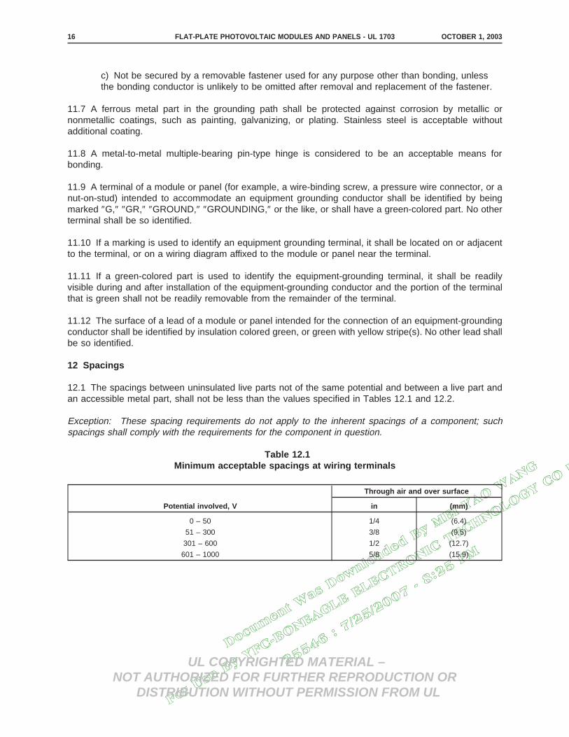
12.1 The spacings between uninsulated live parts not of the same potential and between a live part andan accessible metal part, shall not be less than the values specified in Tables 12.1 and 12.2.
Exception: These spacing requirements do not apply to the inherent spacings of a component; suchspacings shall comply with the requirements for the component in question.
Table 12.1Minimum acceptable spacings at wiring terminals
Potential involved, V
Through air and over surface
in (mm)
0 – 50 1/4 (6.4)
51 – 300 3/8 (9.5)
301 – 600 1/2 (12.7)
601 – 1000 5/8 (15.9)
OCTOBER 1, 2003FLAT-PLATE PHOTOVOLTAIC MODULES AND PANELS - UL 170316

Docum
ent W
as D
ownlo
aded
By M
EI YAO W
ANG
For U
se B
y YFC
-BONEAGLE E
LECTRONIC T
ECHNOLOGY CO L
TD
25546 : 7/25/2007 -
8:25 P
M
UL COPYRIGHTED MATERIAL –NOT AUTHORIZED FOR FURTHER REPRODUCTION OR
DISTRIBUTION WITHOUT PERMISSION FROM UL
Table 12.2Minimum acceptable spacings elsewhere than at wiring terminals
Potential involved, V
Through air Over surface
in (mm) in (mm)
0 – 50 1/16 (1.6) 1/16 (1.6)
51 – 300 1/8 (3.2) 1/4 (6.4)
301 – 600 1/4 (6.4) 3/8 (9.5)
601 – 1000 3/8 (9.5) 1/2 (12.7)
12.2 The spacings at a field-wiring terminal are to be measured with and without wire connected to theterminal. The wire is to be connected as it would be in actual use. If the terminal will properlyaccommodate it, and if the product is not marked to restrict its use, the wire is to be one size larger thanthat required; otherwise, the wire is to be the size required.
12.3 Surfaces separated by a gap of 0.013 in (0.33 mm) or less are considered to be in contact with eachother for the purpose of judging over surface spacings.
12.4 In Tables 12.1 and 12.2, the potential involved is the maximum voltage that may exist between partsduring any anticipated use of the module or panel.
12.5 A barrier or liner of electrical grade fiber providing the sole insulation between a live part and anaccessible metal part or between uninsulated live parts not of the same potential shall not be less than0.028 in (0.71 mm) thick. The barrier or liner shall be held in place and shall not be adversely affected tothe extent that its necessary properties may fall below the minimum values required for the application.
13 Wiring Compartments
13.1 General
13.1.1 A wiring compartment shall comply with the requirements specified in 13.1.2 – 13.3.4.
13.1.2 The internal volume of the wiring compartment shall be in accordance with Table 13.1. The volumeshall be calculated for each conductor intended to be installed, including integral conductors of the moduleor panel. In the space being evaluated for the minimum required volume, no enclosure dimension shall beless than 3/4 in (19.1 mm). The internal volume shall be determined using water as prescribed for theVolume Verification Test in the Standard for Metallic Outlet Boxes, UL 514A.
MARCH 15, 2002 FLAT-PLATE PHOTOVOLTAIC MODULES AND PANELS - UL 1703 17

Docum
ent W
as D
ownlo
aded
By M
EI YAO W
ANG
For U
se B
y YFC
-BONEAGLE E
LECTRONIC T
ECHNOLOGY CO L
TD
25546 : 7/25/2007 -
8:25 P
M
UL COPYRIGHTED MATERIAL –NOT AUTHORIZED FOR FURTHER REPRODUCTION OR
DISTRIBUTION WITHOUT PERMISSION FROM UL
Table 13.1Volume required per conductor
Size of conductor, AWG Free space within box for each conductor, in 3
18 1.50
16 1.75
14 2.00
12 2.25
10 2.50
8 3.00
6 5.00
For SI units: 1 cubic in = 16.4 cm3
13.1.3 A wiring compartment shall have provision for accommodating a wiring system employing araceway or cable.
13.1.4 A wiring compartment shall have no more than one opening when the module or panel is shippedfrom the factory. Tapped holes with screwed-in plugs and knockouts are not considered openings.
13.1.5 Gaskets and seals shall not deteriorate beyond limits during accelerated aging, and shall not beused where they may be subject to flexing during normal operation. See Accelerated Aging Test, Section32.
13.1.6 A wiring compartment that is secured to a substrate by means of an adhesive shall comply withWiring Compartment Securement Test, Section 42.
13.2 Metallic wiring compartments
13.2.1 A wiring compartment of sheet steel shall have a wall thickness of not less than 0.053 in (1.35 mm)if uncoated, or 0.056 in (1.42 mm) if zinc coated.
13.2.2 A wiring compartment of sheet aluminum shall have a wall thickness of not less than 0.0625 in(1.59 mm).
13.2.3 A wiring compartment of cast iron, aluminum, brass, or bronze shall have a wall thickness of notless than 3/32 in (2.4 mm).
13.2.4 A threaded hole in a metal wiring compartment intended for the connection of rigid metal conduitshall be reinforced to provide metal not less than 1/4 in (6.4 mm) thick, and shall be tapered unless aconduit end stop is provided.
13.2.5 If threads for the connection of conduit are tapped all the way through a hole in a compartmentwall, or if an equivalent construction is employed, there shall not be less than 3-1/2 nor more than fivethreads in the metal and the construction shall be such that a conduit bushing can be attached asintended.
MARCH 15, 2002FLAT-PLATE PHOTOVOLTAIC MODULES AND PANELS - UL 170318

Docum
ent W
as D
ownlo
aded
By M
EI YAO W
ANG
For U
se B
y YFC
-BONEAGLE E
LECTRONIC T
ECHNOLOGY CO L
TD
25546 : 7/25/2007 -
8:25 P
M
UL COPYRIGHTED MATERIAL –NOT AUTHORIZED FOR FURTHER REPRODUCTION OR
DISTRIBUTION WITHOUT PERMISSION FROM UL
13.2.6 If threads for the connection of conduit are not tapped all the way through a hole in a compartmentwall, there shall not be less than five full threads in the metal and there shall be a smooth, rounded inlethole for the conductors which shall afford protection to the conductors equivalent to that provided by astandard conduit bushing. The throat diameter of an inlet hole shall be within the limits specified in theStandard for Metallic Outlet Boxes, UL 514A.
13.2.7 For a nonthreaded opening in a metal wiring compartment intended to accommodate rigid metallicconduit, a flat surface of sufficient area as described in the Standard for Metallic Outlet Boxes, UL 514A,shall be provided around the opening to accept the bearing surfaces of the bushing and lock washer.
13.3 Nonmetallic wiring compartments
13.3.1 The considerations mentioned in 7.1 concerning polymeric materials serving as the enclosureapply to nonmetallic wiring compartments.
13.3.2 A nonmetallic wiring compartment intended to accommodate nonmetallic conduit shall have:
a) One or more unthreaded conduit-connection sockets integral with the compartment thatcomply with the requirements in the Standard for Nonmetallic Outlet Boxes, Flush-DeviceBoxes, and Covers, UL 514C,
b) One or more threaded or unthreaded openings for a conduit-connection socket, or
c) One or more knockouts that comply with UL 514C.
13.3.3 With reference to 13.3.2 (b), a module or panel provided with a nonmetallic wiring compartmenthaving a threaded opening shall be marked in accordance with 47.8.
13.3.4 In a nonmetallic compartment, a socket for the connection of nonmetallic conduit shall provide apositive end stop for the conduit; and the socket diameters, the throat diameter at the entrance to the box,the socket depths, and the wall thickness of the socket shall be within the limits specified in the Standardfor Nonmetallic Outlet Boxes, Flush-Device Boxes, and Covers, UL 514C.
13.3.5 A knockout or opening in a nonmetallic wiring compartment intended to accommodate rigidnonmetallic conduit shall comply with the requirements in the Standard for Nonmetallic Outlet Boxes,Flush-Device Boxes, and Covers, UL 514C.
MARCH 15, 2002 FLAT-PLATE PHOTOVOLTAIC MODULES AND PANELS - UL 1703 19

Docum
ent W
as D
ownlo
aded
By M
EI YAO W
ANG
For U
se B
y YFC
-BONEAGLE E
LECTRONIC T
ECHNOLOGY CO L
TD
25546 : 7/25/2007 -
8:25 P
M
UL COPYRIGHTED MATERIAL –NOT AUTHORIZED FOR FURTHER REPRODUCTION OR
DISTRIBUTION WITHOUT PERMISSION FROM UL
14 Corrosion Resistance
14.1 Sheet steel having a thickness of 0.12 in (3.05 mm) or more that may be exposed to the weathershall be made corrosion-resistant by one of the following coatings:
a) Hot-dipped mill-galvanized sheet steel conforming with the coating designation G60 or A60in the Specification for Steel Sheet, Zinc-Coated (Galvanized) or Zinc-Iron Alloy-Coated(Galvannealed) by the Hot Dip Process, ASTM A653/A653M-01, with not less than 40 percentof the zinc on any side, based on the minimum single spot-test requirement in this ASTMspecification. The weight of zinc coating may be determined by any method; however, in caseof question, the weight of coating shall be established in accordance with the Standard TestMethod for Weight of Coating on Zinc-Coated (Galvanized) Iron or Steel Articles, ASTM A90-81(1991).
b) A zinc coating, other than that provided on hot-dipped mill-galvanized sheet steel, uniformlyapplied to an average thickness of not less than 0.00041 in (0.010 mm) on each surface with aminimum thickness of 0.00034 in (0.009 mm). The thickness of the coating shall be establishedby the Metallic Coating Thickness Test, Section 38.
c) An organic or inorganic protective coating system on both surfaces, applied after forming.The results of an evaluation of the coating system shall demonstrate that it provides protectionat least equivalent to that provided by the zinc coating described in 14.1(a). See PolymericMaterials, Section 7 and Corrosive Atmosphere Test, Section 37.
d) Any one of the means specified in 14.2.14.1 revised October 1, 2003
14.2 Sheet steel having a thickness of less than 0.12 in (3.05 mm) which may be exposed to the weathershall be made corrosion-resistant by one of the following coatings:
a) Hot-dipped, mill-galvanized sheet steel conforming with the coating designation G90 in theSpecification for Steel Sheet, Zinc-Coated (Galvanized) or Zinc-Iron Alloy-Coated(Galvannealed) by the Hot Dip Process, ASTM A653/A653M-01, with not less than 40 percentof the zinc on any side, based on the minimum single spot-test requirement in this ASTMspecification. The weight of zinc coating may be determined by any acceptable method;however, in case of question, the weight of coating shall be established in accordance with theStandard Test Method for Weight of Coating on Zinc-Coated (Galvanized) Iron or Steel Articles,ASTM A90-81 (1991).
b) A zinc coating, other than that provided on hot-dipped mill-galvanized sheet steel, uniformlyapplied to an average thickness of not less than 0.00061 in (0.015 mm) on each surface with aminimum thickness of 0.00054 in (0.014 mm). The thickness of the coating shall be establishedby the Metallic-Coating Thickness Test, Section 38. An annealed coating shall also comply with14.5 and 14.6.
c) A cadmium coating not less than 0.0010 in (0.025 mm) thick on both surfaces. The thicknessof the coating shall be established by the Metallic Coating Thickness Test, Section 38.
d) A zinc coating conforming with 14.1(a) or 14.1(b) with one coat of outdoor paint. The coatingsystem shall comply with 14.3.
OCTOBER 1, 2003FLAT-PLATE PHOTOVOLTAIC MODULES AND PANELS - UL 170320

Docum
ent W
as D
ownlo
aded
By M
EI YAO W
ANG
For U
se B
y YFC
-BONEAGLE E
LECTRONIC T
ECHNOLOGY CO L
TD
25546 : 7/25/2007 -
8:25 P
M
UL COPYRIGHTED MATERIAL –NOT AUTHORIZED FOR FURTHER REPRODUCTION OR
DISTRIBUTION WITHOUT PERMISSION FROM UL
e) A cadmium coating not less than 0.00075 in (0.019 mm) thick on both surfaces with onecoat of outdoor paint on both surfaces, or not less that 0.00051 in (0.013 mm) thick on bothsurfaces with two coats of outdoor paint on both surfaces. The thickness of the cadmiumcoating shall be established by the Metallic Coating Thickness Test, Section 38, and the coatingsystem shall comply with 14.3.
14.2 revised October 1, 2003
14.3 With reference to 14.2(d) and 14.2(e), the results of an evaluation of the coating system shalldemonstrate that it provides protection at least equivalent to that provided by the zinc coating as described(G90) in 14.2(a). See Polymeric Materials, Section 7 and Corrosive Atmosphere Test, Section 37.
14.4 With reference to 14.1 and 14.2, other finishes, including paints, other metallic finishes, andcombinations of the two may be accepted when comparative tests with galvanized sheet steel (withoutannealing, wiping, or other surface treatment) conforming with 14.1(a) or 14.2 as applicable, indicate theyprovide equivalent protection. See Corrosive Atmosphere Test, Section 37.
14.5 An annealed coating on sheet steel that is bent or similarly formed or extruded or rolled at edge ofholes after annealing shall additionally be painted in the bent or formed area if the bending or formingprocess damages the zinc coating. If flaking or cracking of a zinc coating at the outside radius of a bentor formed section is visible at 25 power magnification, the zinc coating is considered damaged.
14.6 Simple sheared or cut edges and punched holes are not required to be additionally protected.
14.7 Iron or steel serving as a necessary part of the product but not exposed to the weather shall beplated, painted, or enameled for protection against corrosion.
14.8 Aluminum, stainless steel, and polymeric materials may be used without corrosion-resistant coatingsor platings.
14.9 Materials not specifically mentioned in this section shall be evaluated on an individual basis. Thetests described in Polymeric Material, Section 7, and Corrosive Atmosphere Test, Section 37, may beused for the evaluation.
15 Accessibility of Uninsulated Live Parts
15.1 An accessible part of a module or panel shall not involve a risk of electric shock.
Exception: A part that is not energized when it is accessible need not comply with this requirement.
15.2 In determining whether a part is energized, the module or panel is to be evaluated:
a) Not connected, and
b) Connected in any implied or described acceptable manner. In both cases, the module orpanel is to be in the state described in 15.4 and in the environment described in 20.2.
OCTOBER 1, 2003 FLAT-PLATE PHOTOVOLTAIC MODULES AND PANELS - UL 1703 21

Docum
ent W
as D
ownlo
aded
By M
EI YAO W
ANG
For U
se B
y YFC
-BONEAGLE E
LECTRONIC T
ECHNOLOGY CO L
TD
25546 : 7/25/2007 -
8:25 P
M
UL COPYRIGHTED MATERIAL –NOT AUTHORIZED FOR FURTHER REPRODUCTION OR
DISTRIBUTION WITHOUT PERMISSION FROM UL
15.3 For voltages and currents between parts of the individual unconnected product, voltage is to bedetermined in accordance with 20.2. For voltages and currents between parts of the assembly of products,voltage is to be the maximum system voltage, current is to be the available current.
15.4 A part is considered accessible if, in a fully assembled module or panel (that is, with all covers inplace) the part may be touched by the probe illustrated in Figure 15.1. A cover that may be removedwithout the use of a tool is to be removed for purposes of this requirement. A cover that may be removed(with or without a tool) for routine maintenance such as cleaning, or to gain access to tools, is to beremoved for purposes of this requirement.This is generated text for figtxt.
15.5 The probe illustrated in Figure 15.1 shall be applied to any depth that the opening will permit; andshall be rotated or angled before, during, and after insertion through the opening to any position that isnecessary to examine the product. The probe shall be applied in any possible configuration; and, ifnecessary, the configuration shall be changed after insertion through the opening. The probe is to be usedas a measuring instrument to judge the accessibility provided by an opening, and not as an instrument tojudge the strength of a material; as such, it is to be applied with the minimum force necessary toaccurately determine accessibility.
Figure 15.1Probe for determining accessibility of live parts
OCTOBER 1, 2003FLAT-PLATE PHOTOVOLTAIC MODULES AND PANELS - UL 170322

Docum
ent W
as D
ownlo
aded
By M
EI YAO W
ANG
For U
se B
y YFC
-BONEAGLE E
LECTRONIC T
ECHNOLOGY CO L
TD
25546 : 7/25/2007 -
8:25 P
M
UL COPYRIGHTED MATERIAL –NOT AUTHORIZED FOR FURTHER REPRODUCTION OR
DISTRIBUTION WITHOUT PERMISSION FROM UL
16 Fire Resistance
16.1 A module or panel intended for stand-off, rack, or direct mounting in combination with a specifiedroof, or intended for integral mounting shall comply with the fire resistance requirements for a Class A, B,or C roof covering when the module or panel is indicated or implied as being fire rated. For a combinationconstruction, the rating shall be coincident with, or at a lower level than, the rating of the basic roofcovering material. The fire resistance shall be determined in accordance with the Standard for Tests forFire Resistance of Roof Covering Materials, UL 790, as modified by Fire Tests, Section 31.
17 Superstrate
17.1 A module or panel superstrate shall comply with at least one of the following:
a) The requirements in the Performance Specifications and Methods of Test for Safety GlazingMaterial Used in Buildings, ANSI Z97.1-1984; or
b) The requirements in the Code of Federal Regulations, Title 16 CPSC Part 1201 – SafetyStandard for Architectural Glazing Materials; or
c) The Impact Test, Section 30.
Exception No. 1: Thin-film flexible glazing material having a thickness of 0.01 in (0.254 mm) or less neednot comply with this requirement.
Exception No. 2: Encapsulant that is protected with wire screen or other similar means having openingsthat will not pass a 1/2-in (12.7-mm) diameter hemispherically tipped probe applied with a force of 1 lb(4.4 N).
PERFORMANCE
18 General
18.1 The same test procedures shall be used for the electrical performance measurements required bythe Temperature Test, Section 19, Voltage, Current, and Power Measurements Test, Section 20, andHot-Spot Endurance Test, Section 39 The test procedures described in the following standard shall beapplied where applicable:
a) Standard Tables for Terrestrial Solar Spectral Irradiance at Air Mass 1.5 for 37 Degree TiltedSurface, ASTM G159-1998;
b) Standard Specifications for Solar Simulation for Terrestrial Photovoltaic Testing, ASTME927-91;
c) Standard Methods of Testing Electrical Performance of Nonconcentrator TerrestrialPhotovoltaic Modules and Arrays Using Reference Cells, ASTM E1036-96;
d) Procedures for Temperature Irradiance Corrections to Measured I-V Characteristics ofCrystalline Silicon Photovoltaic Devices, IEC 891;
e) Photovoltaic Devices, Part 1: Measurement of Photovoltaic Current-Voltage Characteristics,IEC 904-1; and
OCTOBER 1, 2003 FLAT-PLATE PHOTOVOLTAIC MODULES AND PANELS - UL 1703 23

Docum
ent W
as D
ownlo
aded
By M
EI YAO W
ANG
For U
se B
y YFC
-BONEAGLE E
LECTRONIC T
ECHNOLOGY CO L
TD
25546 : 7/25/2007 -
8:25 P
M
UL COPYRIGHTED MATERIAL –NOT AUTHORIZED FOR FURTHER REPRODUCTION OR
DISTRIBUTION WITHOUT PERMISSION FROM UL
f) Photovoltaic Devices, Part 3: Measurement Principles for Terrestrial Photovoltaic (PV) SolarDevices With Reference Spectral Irradiance Data, IEC 904-3.
18.1 revised October 1, 2003
18.2 With reference to the tests mentioned in 18.1, parameters may be measured under conditions otherthan specified irradiance, air mass, or temperature, and the values at the specified conditions calculatedusing correction coefficients described in the referenced standards.
18.3 Samples of the module or panel, or partial or representative samples, shall be subjected to the testsindicated in Table 18.1. The order of the tests in Table 18.1 is for convenience only. It is not intended toimply that any one sample be subjected to the complete sequence or a partial sequence of tests unlessspecifically stated in Figure 18.1. Unless one sample is to be subjected to a specific sequence of tests,separate samples are able to be used for each test.
Exception: Samples of a module or panel with a system open-circuit voltage rating less than 30 V anda short-circuit current rating less than 8 A is only required to be subjected to the Temperature, Voltageand Current Measurement, Strain Relief, Push, Bonding Path Resistance, and DielectricVoltage-Withstand Tests.
Table 18.1Module and panel performance
Table 18.1 revised June 30, 2004
Section Test Number of samples
19 Temperature testd 1
20 Voltage and current measurements testd 1
21 Leakage current test 3
22 Strain relief testd 1
23 Push testd 1
24 Cut test 1
25 Bonding path resistance test 3
26 Dielectric voltage-withstand testd 3
27 Wet insulation-resistance test 3
28 Reverse current overload test 1
29 Terminal torque test 1
30 Impact test 1
31 Fire test a
33 Water spray test 1
34 Accelerated aging test b
35 Temperature cycling test 3
36 Humidity test 3
37 Corrosive atmosphere test 2
38 Metallic coating thickness test 1
39 Hot-spot endurance test 1
40 Arcing test c
41 Mechanical loading test 1
42 Wiring compartment securement test 1
a A function of the physical size of the module.b A function of the physical size of the gasket and seal material.c One or more, depending upon test procedure elected.d With reference to the Exception to 18.3, only these tests are needed for a module or panel with the specified ratings.
JUNE 30, 2004FLAT-PLATE PHOTOVOLTAIC MODULES AND PANELS - UL 170324

Docum
ent W
as D
ownlo
aded
By M
EI YAO W
ANG
For U
se B
y YFC
-BONEAGLE E
LECTRONIC T
ECHNOLOGY CO L
TD
25546 : 7/25/2007 -
8:25 P
M
UL COPYRIGHTED MATERIAL –NOT AUTHORIZED FOR FURTHER REPRODUCTION OR
DISTRIBUTION WITHOUT PERMISSION FROM UL
Figure 18.1Test sequences and samples
NOTES –
1 = Section 36
2 = Section 26
3 = Section 21
4 = Section 27
5 = Section 42
6 = Section 35
7 = Section 33
8 = Section 23
JUNE 30, 2004 FLAT-PLATE PHOTOVOLTAIC MODULES AND PANELS - UL 1703 25

Docum
ent W
as D
ownlo
aded
By M
EI YAO W
ANG
For U
se B
y YFC
-BONEAGLE E
LECTRONIC T
ECHNOLOGY CO L
TD
25546 : 7/25/2007 -
8:25 P
M
UL COPYRIGHTED MATERIAL –NOT AUTHORIZED FOR FURTHER REPRODUCTION OR
DISTRIBUTION WITHOUT PERMISSION FROM UL
19 Temperature Test
19.1 When a module or panel is at thermal equilibrium in its intended application mounting at electricalopen circuit and reverse voltage hot-spot heating associated with operation as short-circuit– see 19.5; nopart shall attain a temperature that would:
a) Ignite materials or components;
b) Cause the temperature limits of surfaces, materials, or components, as described in Table19.1, to be exceeded; or
c) Cause creeping, distortion, sagging, charring or similar damage to any part of the product, ifsuch damage or deterioration may impair the performance of the product under therequirements of this standard.
19.1A With reference to 19.1, thermal equilibrium is attained when three successive readings indicate nochange in temperature. These readings shall be taken at the conclusion of three consecutive, equalintervals of time; each interval having a duration of 10 minutes minimum test time. Wind speed andirradiance are to be factored into each measurement.
19.2 Material and component temperatures are to be determined for an ambient temperature of 40°C(104°F), AM 1.5 spectrum, 100 mW/cm2 irradiance as measured in the plane of the module or panel, and1 m/s (2.237 mph) average wind speed. The ambient temperature may be in the range of 10 to 55°C (50to 131°F), in which case each observed temperature shall be corrected by the addition (if the ambienttemperature is below 40°C) or subtraction (if the ambient temperature is above 40°C) of the differencebetween 40°C and the observed ambient temperature. If the irradiance is other than 100 mW/cm2,temperatures for numerous irradiance levels are to be determined, and a linear extrapolation conductedto determine the temperature under 100mW/cm2 irradiance.
19.3 If an unacceptable performance is encountered during the temperature test, and the performance isattributed to a test condition that, although within the limits specified, may be considered more severe thannecessary; for example an ambient temperature near the limits allowed (10 or 55°C), the test may bereconducted under conditions closer to the norm.
19.4 For the determination of temperatures, a module or panel is to be operated under both open- andshort-circuit conditions.
19.5 To cover the hot-spot heating effect caused by reverse voltage operation of a cell, a cell is to beshadowed during the short-circuit condition of the temperature test by covering one-half of one of the cellsof the module or panel with black vinyl tape, 0.007 in (0.18 mm) thick in direct contact with the superstrateso that this cell is not fully irradiated. During this test, the modules or panels are to be connected in serieswithout bypass diodes to the extent that is permitted by the marking specified in 47.9. The temperaturesof the shaded cell and adjacent area are to be measured.
19.6 A module or panel is to be installed according to the instructions provided with it. If the instructionsdo not describe the accommodating structure, spacings, and the like, the module or panel is to bemounted as described in 19.8 – 19.10.
JUNE 30, 2004FLAT-PLATE PHOTOVOLTAIC MODULES AND PANELS - UL 170326

Docum
ent W
as D
ownlo
aded
By M
EI YAO W
ANG
For U
se B
y YFC
-BONEAGLE E
LECTRONIC T
ECHNOLOGY CO L
TD
25546 : 7/25/2007 -
8:25 P
M
UL COPYRIGHTED MATERIAL –NOT AUTHORIZED FOR FURTHER REPRODUCTION OR
DISTRIBUTION WITHOUT PERMISSION FROM UL
19.7 With reference to 19.8 and 19.9, the type of mounting intended, (for example, stand-off, direct, andthe like) is to be determined from the construction of the module or panel. If more than one type ofmounting is possible, the module or panel is to be tested in each such mounting, unless one mountingcan be shown to represent all.
19.8 A module or panel intended for direct mounting on a roof or wall surface is to be mounted on aplatform constructed of wood, pressed wood, or plywood, 3/4 in (19 mm) thick (See Figure 19.1). Theplatform is to be painted flat black on the side facing the test sample. The platform is to extend at least 2ft (0.6 m) beyond the module or panel on all sides.
19.9 A module or panel intended for stand-off or rack mounting on a roof, wall, or the ground is to bemounted on a frame constructed from 2 in by 4 in (trade size) lumber. Two frame members are to belocated at the outside edges of the underside of the module or panel, and are to be oriented longitudinallyalong the long axis of the module or panel. Additional frame members are to be located at the outsideedges of the underside of the module or panel along its short axis. If the distance between the two outershort axis members exceeds 2 ft (0.6 m), an additional frame member is to be located at the center lineof the module or panel assembly. The frame is to be secured to a platform as described in 19.8 with a 4-ft(1.22-m) spacing between the back of the module or panel and the platform (See Figure 19.2). The frameis to be painted flat black on the side facing the test sample.
19.10 A module or panel intended for integral mounting within a roof or wall is to be tested while mountedon a platform constructed as described in 19.8 with the module or panel boxed in on all sides by 1-in thick(trade size) wood boards that are wide enough to cover the entire outer edge (See Figure 19.3). Theboards are to be painted flat black on the side facing the sample.
Table 19.1Maximum temperatures
Table 19.1 revised October 1, 2003
Part, material, or component
Temperature
°C (°F)
1. Insulating materials:d
Polymeric a a
Varnished cloth 85 185
Fiber 90 194
Laminated phenolic composition 125 257
Molded phenolic composition 150 302
2. Sealing compoundd b b
3. Field wiring terminalsc 60 140
4. Field wiring compartments that wires may contactc 60 140
5. Insulated conductors Rated Temperature
6. Wood and wood products 90 194
7. Surfaces accessible to contact e e
8. Mounting surface and adjacent structural membersd 90 194
a For the open-circuit mode, the relative thermal index, less 20°C (36°F). For reverse voltage hot-spot heating under short-circuit conditions, the relative thermal index.b The maximum sealing compound temperature, when corrected to a 40°C (104°F) ambient temperature, is to be 15°C (27°F)less than the softening point of the compound as determined by the Standard Test Method for Softening Point by Ring and BallApparatus, ASTM E28-99.c If a marking is provided in accordance with 47.5, the temperatures observed on the terminals and at points within a wiringcompartment may exceed the value specified but shall not attain a temperature higher than 90°C (194°F).
OCTOBER 1, 2003 FLAT-PLATE PHOTOVOLTAIC MODULES AND PANELS - UL 1703 27
Table 19.1 Continued on Next Page
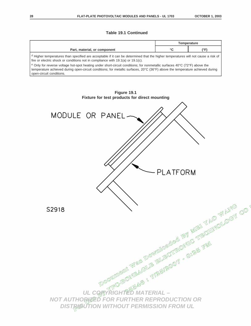
Docum
ent W
as D
ownlo
aded
By M
EI YAO W
ANG
For U
se B
y YFC
-BONEAGLE E
LECTRONIC T
ECHNOLOGY CO L
TD
25546 : 7/25/2007 -
8:25 P
M
UL COPYRIGHTED MATERIAL –NOT AUTHORIZED FOR FURTHER REPRODUCTION OR
DISTRIBUTION WITHOUT PERMISSION FROM UL
Table 19.1 Continued
Part, material, or component
Temperature
°C (°F)
d Higher temperatures than specified are acceptable if it can be determined that the higher temperatures will not cause a risk offire or electric shock or conditions not in compliance with 19.1(a) or 19.1(c).e Only for reverse voltage hot-spot heating under short-circuit conditions; for nonmetallic surfaces 40°C (72°F) above thetemperature achieved during open-circuit conditions; for metallic surfaces, 20°C (36°F) above the temperature achieved duringopen-circuit conditions.
This is generated text for figtxt.
This is generated text for figtxt.
Figure 19.1Fixture for test products for direct mounting
OCTOBER 1, 2003FLAT-PLATE PHOTOVOLTAIC MODULES AND PANELS - UL 170328

Docum
ent W
as D
ownlo
aded
By M
EI YAO W
ANG
For U
se B
y YFC
-BONEAGLE E
LECTRONIC T
ECHNOLOGY CO L
TD
25546 : 7/25/2007 -
8:25 P
M
UL COPYRIGHTED MATERIAL –NOT AUTHORIZED FOR FURTHER REPRODUCTION OR
DISTRIBUTION WITHOUT PERMISSION FROM UL
Figure 19.2Fixture for test products for stand-off or rack mounting
MARCH 15, 2002 FLAT-PLATE PHOTOVOLTAIC MODULES AND PANELS - UL 1703 29

Docum
ent W
as D
ownlo
aded
By M
EI YAO W
ANG
For U
se B
y YFC
-BONEAGLE E
LECTRONIC T
ECHNOLOGY CO L
TD
25546 : 7/25/2007 -
8:25 P
M
UL COPYRIGHTED MATERIAL –NOT AUTHORIZED FOR FURTHER REPRODUCTION OR
DISTRIBUTION WITHOUT PERMISSION FROM UL
This is generated text for figtxt.
19.11 Temperatures are to be measured by means of thermocouples. Thermocouples exposed toirradiation are to be shielded from the direct effect of such irradiation. A thermocouple junction is to besecurely held in positive thermal contact with the surface of the material the temperature of which is beingmeasured. Thermal contact may be achieved by securely cementing the thermocouple in place. For ametal surface, brazing, welding, or soldering the thermocouple to the metal may be used. A thermocouplejunction may be secured to wire insulation or wood surfaces by taping.
19.12 Thermocouples consisting of No. 30 AWG (0.05 mm2) iron and constantan wires are to beemployed. However, when it is not practical to use iron and constantan thermocouples some other typedescribed in Initial Calibration Tolerances for Thermocouples table in Temperature MeasurementThermocouples, ANSI/ISA, MC96.1, is to be used.
Figure 19.3Fixture for test products for integral mounting
MARCH 15, 2002FLAT-PLATE PHOTOVOLTAIC MODULES AND PANELS - UL 170330

Docum
ent W
as D
ownlo
aded
By M
EI YAO W
ANG
For U
se B
y YFC
-BONEAGLE E
LECTRONIC T
ECHNOLOGY CO L
TD
25546 : 7/25/2007 -
8:25 P
M
UL COPYRIGHTED MATERIAL –NOT AUTHORIZED FOR FURTHER REPRODUCTION OR
DISTRIBUTION WITHOUT PERMISSION FROM UL
20 Voltage, Current and Power Measurements Test
20.1 The short-circuit current (ISC), rated current (Ir) maximum power (Pmax), and open-circuit voltage(VOC) shall be within ± 10 percent of the rated value – See 43.1 and 44.1(c) – under conditions of:
a) Standard test conditions (STC) and
b) For Ir and Pmax, also at normal operating cell temperature (NOCT).
20.2 For purposes of accessibility to individual module or panel live parts as specified in 15.3, the voltageis to be determined under conditions of open circuit, an irradiance of 100 mW/cm2, AM1.5 and a celltemperature of minus 20°C (minus 4°F).
21 Leakage Current Test
21.1 The leakage current of a module having a marked maximum system voltage of more than 30 V shallnot be greater than the values specified in Table 21.1 when tested as described in 21.2 – 21.7.
21.2 The test is to be conducted on three unconditioned modules, and the modules that have beensubjected to the Water Spray Test, Section 31; the Temperature Cycling Test, Section 33; and theHumidity Test, Section 34. The leakage current of the unconditioned modules is to be measured with themodule cell temperature at 25 ±3°C (77 ±5°F), and then with the cells at NOCT ±2°C (±3.6°F). If panelsare used for the Water Spray Test, a module of a panel is to be used for the Leakage Current Test.
Table 21.1Allowable leakage current
Surface or part from which measurement is made Maximum current (dc)
Accessible conductive frame, pan, or the like 10 µA
Accessible circuit parts 1 mA
Conductive foil over accessible insulating surfaces 1 mA
21.3 Leakage current refers to all currents that may be conveyed between accessible parts of a modulewhen the module is connected to the source described in 21.4 and 21.5.
21.4 The dc test voltage is to be at a level equal to the rated maximum system voltage.
21.5 All accessible parts and surfaces are to be tested for leakage current. The positive and negativeterminals of an unilluminated module are to be connected together and to one terminal of a dc powersupply. Both polarities of the source connection are to be used, unless it can be shown that one polaritywill represent both. Leakage currents are to be measured between the part or surface and the otherterminal of the power supply. Leakage current is to be measured with the meter described in 21.7.
21.6 When leakage current is measured at an insulating surface, a 40 cm by 20 cm conductive foil is tobe in contact with the surface, and the measurement is to be made from the foil. If the surface is less than40 cm by 20 cm, the foil is to be the same size as the surface.
MARCH 15, 2002 FLAT-PLATE PHOTOVOLTAIC MODULES AND PANELS - UL 1703 31

Docum
ent W
as D
ownlo
aded
By M
EI YAO W
ANG
For U
se B
y YFC
-BONEAGLE E
LECTRONIC T
ECHNOLOGY CO L
TD
25546 : 7/25/2007 -
8:25 P
M
UL COPYRIGHTED MATERIAL –NOT AUTHORIZED FOR FURTHER REPRODUCTION OR
DISTRIBUTION WITHOUT PERMISSION FROM UL
21.7 With reference to 21.5, the meter for the measurement is to be responsive to dc only, and is to havean input impedance of 500 ohms.
22 Strain Relief Test
22.1 A lead or cable for connection to external wiring, or a lead or cable terminated at both ends on theproduct but which may be subjected to handling during installation or routine servicing of a module orpanel shall withstand for 1 min a force of 20 lb (89 N) applied in any direction permitted by theconstruction, without damage to the lead or cable, its connecting means, and the module or panel.
22.2 A separable connector not enclosed by a wiring compartment, and such connector’s joining to itsmating connector, shall withstand for 1 min a force of 20 lb (89 N) applied in any direction permitted bythe construction, either directly or through any wire or cable attached to the mating connector, withoutdamage to the connector, the module or panel, or the mounting of the connector to the module or panel,or separation of the two mating connectors.
23 Push Test
23.1 A module or panel shall be capable of withstanding for 1 min the application to any point of:
a) A 20 lb (89 N) force applied by a 1/2-in (12.7-mm) diameter steel rod, the end of which isrounded to a 1/2-in diameter hemisphere, and
b) A 4 lb (17.8 N) force applied by a 1/16-in (1.6-mm) diameter steel rod, the end of which isrounded to a 1/16-in diameter hemisphere,
without creating a risk of fire, electric shock, or injury to persons.
23.2 A risk of fire is considered to exist, if, as a result of the application of either probe, parts of themodule are displaced to the extent that arcing between parts of available current and voltage in the ″ARCTEST″ zone, Figure 40.1, is likely.
23.3 A risk of electric shock is considered to exist if:
a) A part involving a risk of electric shock is contacted by the applied probe;
b) A part involving a risk of electric shock is rendered accessible (transitory or permanent) as aresult of the application of either probe; or
c) There is a reduction in resistance between a part involving a risk of electric shock and anaccessible part such that the module or panel would not comply with the Leakage Current Test,Section 21.
23.4 A risk of injury to persons is considered to exist, if, as a result of the application of either probe, partsare displaced or broken so as to expose edges which would not comply with the requirements for sharpedges in 6.9.
MARCH 15, 2002FLAT-PLATE PHOTOVOLTAIC MODULES AND PANELS - UL 170332

Docum
ent W
as D
ownlo
aded
By M
EI YAO W
ANG
For U
se B
y YFC
-BONEAGLE E
LECTRONIC T
ECHNOLOGY CO L
TD
25546 : 7/25/2007 -
8:25 P
M
UL COPYRIGHTED MATERIAL –NOT AUTHORIZED FOR FURTHER REPRODUCTION OR
DISTRIBUTION WITHOUT PERMISSION FROM UL
24 Cut Test
24.1 A module or panel shall withstand the application of a sharp object drawn across its superstrate andsubstrate surfaces without creating a condition described in 2.7.
Exception: Glass surfaces are not required to be tested.
24.2 The module or panel is to be positioned in a horizontal plane with the surface to be tested facingupward. The tool illustrated in Figure 24.1 is to be placed on the surface for 1 min, and then drawn acrossthe test surface of the module or panel at a speed of 6 ±1.2 in/s (152.4 ±30.5 mm/s).
24.3 A condition as described in 2.7 exists when the blade of the tool illustrated in Figure 24.1, contactsa part described in 2.7, or such a part is rendered accessible (transitory or permanent) as a result of theplacement of the blade on, or the drawing of the blade across, the surface.
This is generated text for figtxt.
MARCH 15, 2002 FLAT-PLATE PHOTOVOLTAIC MODULES AND PANELS - UL 1703 33

Docum
ent W
as D
ownlo
aded
By M
EI YAO W
ANG
For U
se B
y YFC
-BONEAGLE E
LECTRONIC T
ECHNOLOGY CO L
TD
25546 : 7/25/2007 -
8:25 P
M
UL COPYRIGHTED MATERIAL –NOT AUTHORIZED FOR FURTHER REPRODUCTION OR
DISTRIBUTION WITHOUT PERMISSION FROM UL
Figure 24.1Cut test tool
A – 5-7/8 in (149 mm) from axis to center of weight.
B – 6-5/8 in (168 mm) from axis to test point.
C – Test point – 0.025 in (0.64 mm) thick carbon steel strip.
Q – Total force exerted at test point Q; 2 lb (907 g).
MARCH 15, 2002FLAT-PLATE PHOTOVOLTAIC MODULES AND PANELS - UL 170334

Docum
ent W
as D
ownlo
aded
By M
EI YAO W
ANG
For U
se B
y YFC
-BONEAGLE E
LECTRONIC T
ECHNOLOGY CO L
TD
25546 : 7/25/2007 -
8:25 P
M
UL COPYRIGHTED MATERIAL –NOT AUTHORIZED FOR FURTHER REPRODUCTION OR
DISTRIBUTION WITHOUT PERMISSION FROM UL
25 Bonding Path Resistance Test
25.1 The resistance between the grounding terminal or lead and any accessible conductive part shall notbe more than 0.1 ohm when measured in accordance with 25.2.
25.2 A current equal to twice the fuse ampere rating specified in accordance with 47.10 is to be passedbetween the grounding terminal or lead and the conductive part. The resistance is to be calculated usingthe voltage drop measured between the grounding terminal or lead and a point within 1/2 in (12.7 mm) ofthe point of current injection.
25.3 If more than one test is needed to evaluate all the paths of conduction between accessible metalparts, there is to be a cooling time of at least 15 min between tests.
25.4 The test is to be conducted on three unconditioned samples.
26 Dielectric Voltage-Withstand Test
26.1 The insulation and spacings between live parts and accessible conductive parts and between liveparts and exposed nonconductive surfaces shall withstand the application of a dc test voltage equal to twotimes the system voltage plus 1000 V without the leakage current between these two points exceeding 50µA dc. The voltage is to be applied in both polarities.
Exception: For a module or panel with a system voltage rating of 30 V or less, the applied voltage is tobe 500 V.
26.2 The test voltage is to be applied between all current-carrying parts and all accessible parts.
26.3 The voltage is to be increased from zero at a substantially uniform rate as described in 26.4, so asto reach the specified test potential in approximately 5 s, and then is to be held at the required test voltageuntil the leakage current is stabilized for at least 1 min. The module or panel is to be observed during thetest and there are to be no signs of arcing or flash-over.
26.4 With reference to 26.3, the test voltage is to be gradually and smoothly increased to the specifiedvalue so that:
a) There are no transients that may cause the instantaneous voltage to exceed the peak valuespecified, and
b) The flow of capacitive current, due to charging, does not cause the test device to indicatebreakdown.
26.5 The test is to be conducted on three unconditioned samples, and the samples that have beensubjected to the Water Spray Test, Section 33; the Temperature Cycling Test, Section 35; the HumidityTest, Section 36; and the Corrosive Atmosphere Test, Section 37. The unconditioned samples are to beat both room temperature and also as heated from the short-circuit operation portion of the temperaturetest in Section 19.
MARCH 15, 2002 FLAT-PLATE PHOTOVOLTAIC MODULES AND PANELS - UL 1703 35

Docum
ent W
as D
ownlo
aded
By M
EI YAO W
ANG
For U
se B
y YFC
-BONEAGLE E
LECTRONIC T
ECHNOLOGY CO L
TD
25546 : 7/25/2007 -
8:25 P
M
UL COPYRIGHTED MATERIAL –NOT AUTHORIZED FOR FURTHER REPRODUCTION OR
DISTRIBUTION WITHOUT PERMISSION FROM UL
26.6 For tests on exposed surfaces of insulating parts, the part is to be covered with conductive foil orthe equivalent.
26.7 The equipment for conducting the dielectric voltage-withstand test is to have the followingcharacteristics:
a) A means for indicating the test voltage that is being applied to the product under test;
b) A sensitivity such that a current in excess of 50 µA across the output indicates unacceptableperformance; and
c) A capacity of at least 500 VA.
Exception: The capacity may be lower if the means for indicating the test voltage is located in the outputcircuit – to maintain the potential indicated in 26.1 except in the case of breakdown. The voltage of thesource is to be continuously adjustable.
27 Wet Insulation-Resistance Test
27.1 As a result of the test described in 27.2 and 27.3:
a) There shall not be dielectric breakdown or surface tracking as a result of the applied dcvoltage;
b) For a module with an area 0.1 m2 or less, the insulation resistance shall not be less than400 MΩ; and
c) For a module with an area larger than 0.1 m2, the measured insulation resistance times thearea of the module shall not be less than 40 MΩ•m2.
27.1 revised October 1, 2003
27.2 The laminate portion of the module or panel is to be immersed in a non-corrosive liquid agent(surfactant) solution. The liquid agent is to have 35 ohm-meter maximum resistance, 0.03 N/m maximumsurface tension, and a temperature of 22 ±3°C (72 ±5°F). Terminal boxes and pigtail-leads or otherconnectors are to be maintained above the solution level and are to be thoroughly wetted by pouring thesolution over these areas. Uninsulated terminations are not to be wetted.
27.3 After two min of immersion in the solution, the insulation resistance between the shorted outputterminals of the module or panel and the solution is to be measured, in both polarities, with an instrumenthaving a voltage of 500 Vdc.
OCTOBER 1, 2003FLAT-PLATE PHOTOVOLTAIC MODULES AND PANELS - UL 170336

Docum
ent W
as D
ownlo
aded
By M
EI YAO W
ANG
For U
se B
y YFC
-BONEAGLE E
LECTRONIC T
ECHNOLOGY CO L
TD
25546 : 7/25/2007 -
8:25 P
M
UL COPYRIGHTED MATERIAL –NOT AUTHORIZED FOR FURTHER REPRODUCTION OR
DISTRIBUTION WITHOUT PERMISSION FROM UL
28 Reverse Current Overload Test
28.1 There shall not be flaming or charring of the cheesecloth or tissue paper in contact with a moduleor panel, or flaming of the module or panel itself for 15 s or more, when a reverse current equal to 135percent of the module or panel series fuse rating current (See 47.10) is caused to flow through the moduleor panel.
28.2 To determine whether a module or panel complies with the requirements in 28.1, a module or panelis to be placed on a single layer of white tissue paper over a 3/4 in (19.1 mm) thick pine board andcovered with a single layer of cheesecloth. The cheesecloth is to be untreated cotton cloth running 14 –15 square yards/lb (26 – 28 m2/kg) and having what is known to the trade as a count of 32 by 28.
28.3 For the test required by 28.1, any blocking diode provided as a part of the module or panel is to bedefeated (short-circuited).
28.4 The test required by 28.1 is to be conducted in an area free of drafts, and the irradiance on themodule or panel is to be less than 5 mW/cm2.
28.5 The test required by 28.1 is to be continued for 2 h or until ultimate results are known, whicheveroccurs first.
29 Terminal Torque Test
29.1 A wire-binding screw or nut on a wiring terminal shall be capable of withstanding 10 cycles oftightening to and releasing from the applicable value of torque specified in Table 29.1 without:
a) Damage to the terminal supporting member,
b) Loss of continuity, or
c) Short circuiting of the electrical circuit to accessible metal.
Table 29.1Torque requirements
Screw size
Torque
Lbf-in (N·m)
No. 6 12 (1.4)
No. 8 16 (1.8)
No. 10 20 (2.3)
OCTOBER 1, 2003 FLAT-PLATE PHOTOVOLTAIC MODULES AND PANELS - UL 1703 37
Docum
ent W
as D
ownlo
aded
By M
EI YAO W
ANG
For U
se B
y YFC
-BONEAGLE E
LECTRONIC T
ECHNOLOGY CO L
TD
25546 : 7/25/2007 -
8:25 P
M
UL COPYRIGHTED MATERIAL –NOT AUTHORIZED FOR FURTHER REPRODUCTION OR
DISTRIBUTION WITHOUT PERMISSION FROM UL
30 Impact Test
30.1 A polymeric material serving as the enclosure of a part involving a risk of fire or electric shock anda superstrate material evaluated in accordance with 17.1(c) are to be subjected to the tests described in30.2 and 30.3.
30.2 When a module or panel is impacted as described in 30.3, there shall be no accessible live parts asdefined in Accessibility of Uninsulated Live Parts, Section 15. Breakage of the superstrate material isacceptable provided there are no particles larger than 1 square in (6.5 cm2) released from their normalmounting position.
30.3 A module or panel is to be mounted in a manner representative of its intended use, and is to besubjected to a 5 ft-lb (6.78 J) impact normal to the surface resulting from a 2-in (51-mm) diameter smoothsteel sphere weighing 1.18 lb (535 g) falling through a distance of 51 in (1.295 m). The module or panelis to be struck at any point considered most vulnerable. If the construction of a module or panel does notpermit it to be struck free from above by the free falling sphere, the sphere is to be suspended by a cordand allowed to fall as a pendulum through the vertical distance of 51 in with the direction of impact normalto the surface. For a polymeric wiring enclosure, the test is to be performed on the enclosure at 25°C(77°F) and also after being cooled and maintained for 3 h at a temperature of minus 35.0 ±2.0°C (minus31.0 ±3.6°F).
30.3 revised October 1, 2003
31 Fire Tests
31.1 Spread-of-flame test
31.1.1 A module or panel intended for roof mounting, and designated for installation above, upon, orintegral with a building roof structure having a surface consisting of a Class A, Class B, or Class C typeroof covering material, shall be subjected to a spread-of-flame test as described in Tests for FireResistance of Roof Covering Materials, UL 790. At no time during or after the tests shall:
a) Any portion of the module or panel be blown off or fall off the test deck in the form of flamingor glowing brands;
b) Portions of the roof deck, or portions of a module or panel intended for installation integralwith or forming a part of the building roof structure, fall away in the form of glowing particles;
c) The flame spread beyond 6 ft (1.82 m) for Class A, 8 ft (2.4 m) for Class B, or 13 ft (3.9 m)for Class C rating. The flame spread is to be measured from the leading edge of the sample; or
d) There be significant lateral spread-of-flame from the path directly exposed to the test flame.Spread-of-flame includes flaming on both the top surface (the surface to which the externalflame is applied) and in any intermediate channel, such as the space between stand-off orintegral modules and a shingle roof.
31.1.2 For a module or panel intended for installation above a building roof structure, theSpread-Of-Flame Test is to be conducted with the module or panel oriented with respect to the test flamesuch that the flame impinges only on the top surface of the module or panel.
OCTOBER 1, 2003FLAT-PLATE PHOTOVOLTAIC MODULES AND PANELS - UL 170338

Docum
ent W
as D
ownlo
aded
By M
EI YAO W
ANG
For U
se B
y YFC
-BONEAGLE E
LECTRONIC T
ECHNOLOGY CO L
TD
25546 : 7/25/2007 -
8:25 P
M
UL COPYRIGHTED MATERIAL –NOT AUTHORIZED FOR FURTHER REPRODUCTION OR
DISTRIBUTION WITHOUT PERMISSION FROM UL
31.2 Burning-brand test
31.2.1 A module or panel intended for roof mounting, and designated for installation above, upon, orintegral with a building roof structure having a surface consisting of a Class A, Class B, or Class C typeroof covering material, shall be subjected to a burning-brand test as described in Tests for fire Resistanceof Roof Covering Materials, UL 790. At no time during or after the tests shall:
a) Any portion of the module or panel or be blown off or fall off the test deck in the form offlaming or glowing brands;
b) The brand burn a hole through the roof covering or through any part of the module or panel;
c) Portions of a module or panel intended for installation integral with, or forming a part of, thebuilding roof structure fall away in the form of glowing particles; or
d) There be sustained flaming of the module or panel.
OCTOBER 1, 2003 FLAT-PLATE PHOTOVOLTAIC MODULES AND PANELS - UL 1703 38A

Docum
ent W
as D
ownlo
aded
By M
EI YAO W
ANG
For U
se B
y YFC
-BONEAGLE E
LECTRONIC T
ECHNOLOGY CO L
TD
25546 : 7/25/2007 -
8:25 P
M
UL COPYRIGHTED MATERIAL –NOT AUTHORIZED FOR FURTHER REPRODUCTION OR
DISTRIBUTION WITHOUT PERMISSION FROM UL
OCTOBER 1, 2003FLAT-PLATE PHOTOVOLTAIC MODULES AND PANELS - UL 170338B
No Text on This Page

Docum
ent W
as D
ownlo
aded
By M
EI YAO W
ANG
For U
se B
y YFC
-BONEAGLE E
LECTRONIC T
ECHNOLOGY CO L
TD
25546 : 7/25/2007 -
8:25 P
M
UL COPYRIGHTED MATERIAL –NOT AUTHORIZED FOR FURTHER REPRODUCTION OR
DISTRIBUTION WITHOUT PERMISSION FROM UL
32 General
32.1 For both the Spread-Of-Flame and Burning-Brand Tests, the test severity (Class A, B, or C) shall becommensurate with the intended designated Class of roof covering material.
32.2 For both the Spread-Of-Flame and Burning-Brand Tests, the module or panel is to be installed inaccordance with the instructions supplied with it. The mounting hardware furnished with the module orpanel, or the mounting means recommended in the instructions, is to be used to mount the module orpanel for the test. The slope of the module or panel with respect to the horizontal is to be the minimumslope specified in the installation instructions. The slope of the simulated roof deck shall not exceed 5 in/ft(416 mm/m).
32.3 A module or panel is not required to be usable after any of the tests of this section.
32.4 For each fire classification requested, only one of each Burning-Brand and Spread-Of-Flame Testsare required to be conducted.
33 Water Spray Test
33.1 A module or panel shall be subjected to a water spray test as described in 33.2 – 33.8. The test shallnot result in water on uninsulated live parts or the collection of water in a compartment containing liveparts. Immediately following the test, the module or panel shall comply with:
a) Dielectric Voltage-Withstand Test, Section 26; and
b) Leakage Current Test, Section 21.
Both the Dielectric Voltage-Withstand Test and the Leakage Current Test are to be conducted without anydrying of the samples.
33.2 A module or panel is to be mounted and oriented in a manner representative of its intended use inthe focal area of the apparatus described in 33.5. If the mounting or orientation of the module or panelunder the water spray may affect the results, the test is to be conducted with the module or panel in thosemountings and orientations deemed necessary to represent any application of the product, consideringalso that the mounting may be on a tracking frame which alters the module orientation.
33.3 If a module or panel is intended to be mounted as an integral part of the roof with an adjacentmodule or panel in an array using factory-designed joining sections, the test is to be conducted using thejoining hardware in accordance with the installation instructions.
33.4 Field wiring connections are to be made in accordance with the wiring method specified in theinstallation instructions. When more than one wiring method is specified, the method least likely to restrictthe entrance of water into the field wiring compartment is to be used.
33.5 The rain test apparatus is to consist of three spray heads mounted in a water supply rack asillustrated in Figure 33.1. Spray heads are to be constructed in accordance with Figure 33.2. The waterpressure for all tests is to be maintained at 5 psig (34.5 kPa) at each head. The distance between thecenter nozzle and the product is to be approximately 3 ft (0.9 m). The product is to be brought into thefocal area of the three spray heads in such position and under such conditions so as to present thegreatest quantity of water to entrances to the product. The spray is to be directed toward the module orpanel at an angle of 45 degrees to the vertical.
MARCH 15, 2002 FLAT-PLATE PHOTOVOLTAIC MODULES AND PANELS - UL 1703 39

Docum
ent W
as D
ownlo
aded
By M
EI YAO W
ANG
For U
se B
y YFC
-BONEAGLE E
LECTRONIC T
ECHNOLOGY CO L
TD
25546 : 7/25/2007 -
8:25 P
M
UL COPYRIGHTED MATERIAL –NOT AUTHORIZED FOR FURTHER REPRODUCTION OR
DISTRIBUTION WITHOUT PERMISSION FROM UL
This is generated text for figtxt.
Figure 33.1Rain-test spray-head piping
Item in mm
A 28 710
B 55 1400
C 2-1/4 55
D 9 230
E 3 75
MARCH 15, 2002FLAT-PLATE PHOTOVOLTAIC MODULES AND PANELS - UL 170340

Docum
ent W
as D
ownlo
aded
By M
EI YAO W
ANG
For U
se B
y YFC
-BONEAGLE E
LECTRONIC T
ECHNOLOGY CO L
TD
25546 : 7/25/2007 -
8:25 P
M
UL COPYRIGHTED MATERIAL –NOT AUTHORIZED FOR FURTHER REPRODUCTION OR
DISTRIBUTION WITHOUT PERMISSION FROM UL
This is generated text for figtxt.
Figure 33.2Rain-test spray head
Item in mm Item in mm
A 1-7/32 31.0 N 1/32 0.80
B 7/16 11.0 P .575 14.61
C 9/16 14.0 .576 14.63
D .578 14.68 Q .453 11.51
.580 14.73 .454 11.53
E 1/64 0.40 R 1/4 6.35
F c c S 1/32 0.80
G .06 1.52 T (No. 35)b 2.79
H (No. 9)b 5.0 U (No. 40)b 2.49
J 23/32 18.3 V 5/8 16.0
K 5/32 3.97 W 0.06 1.52
L 1/4 6.35
M 3/32 2.38
a Molded nylon Rain-Test Spray Heads are available from Underwriters Laboratories, Inc.b ANSI B94.11 Drill Size.c Optional M To serve as wrench grip.
MARCH 15, 2002 FLAT-PLATE PHOTOVOLTAIC MODULES AND PANELS - UL 1703 41

Docum
ent W
as D
ownlo
aded
By M
EI YAO W
ANG
For U
se B
y YFC
-BONEAGLE E
LECTRONIC T
ECHNOLOGY CO L
TD
25546 : 7/25/2007 -
8:25 P
M
UL COPYRIGHTED MATERIAL –NOT AUTHORIZED FOR FURTHER REPRODUCTION OR
DISTRIBUTION WITHOUT PERMISSION FROM UL
33.6 The water for the test is to have a resistivity before the test of 3500 ±175 ohm-cm at 25°C (77°F).At the conclusion of the test, the resistivity of the water is not to be less than 3200 ohm-cm nor more than3800 ohm-cm at 25°C.
33.7 The exposure time is to be 1 h.
33.8 After exposure, the module or panel is to be examined for evidence of water penetration to andabove uninsulated live parts and for evidence of the collection of water in any compartment containing liveparts. If drain holes are provided, consideration is to be given to their preventing the water level fromreaching uninsulated live parts.
34 Accelerated Aging Test
34.1 Materials used for gaskets, seals, and the like (other than cork, fibrous material, and similarproducts) shall have the physical properties as specified in Table 34.1, and shall comply with the physicalproperty requirements of Table 34.2. The material shall not deform, melt, or harden to a degree whichwould affect its sealing properties.
Table 34.1Physical property requirements
Table 34.1 revised October 1, 2003
Minimum tensile strength a Minimum ultimate elongation a Compressive set c, maximum set
Silicone rubber – 500 psi (3.45 MPa) 100 percent 15 percent
Flexible cellular materials (that is such asfoam rubber) – 65 psi (0.448 MPa)
100 percent d
Other Elastomers – 1500 psi (10.3 MPa)b 300 percentb 15 percent
Nonelastomers (excluding cork, fiber andsimilar
200 percent 15 percent
materials)– 1500 psi (10.3 MPa)b
a Tensile strength and ultimate elongation are to be determined using Die C specimens described in the Standard Test Methodsfor Rubber Properties in Tension, ASTM D 412-98 or Type I specimens described in the Standard Test Method for TensileProperties of Plastics, ASTM D 638-01.b As an alternate, an ultimate elongation of 200 percent is acceptable providing that the tensile strength is at least 2200 psi(15.1 MPa).c Compressive set is to be determined 30 min after specimen release using the Standard Test for Rubber Property-Compression Set, ASTM D395-01, Method B.d Compressive set is not applicable to flexible cellular materials.
OCTOBER 1, 2003FLAT-PLATE PHOTOVOLTAIC MODULES AND PANELS - UL 170342

Docum
ent W
as D
ownlo
aded
By M
EI YAO W
ANG
For U
se B
y YFC
-BONEAGLE E
LECTRONIC T
ECHNOLOGY CO L
TD
25546 : 7/25/2007 -
8:25 P
M
UL COPYRIGHTED MATERIAL –NOT AUTHORIZED FOR FURTHER REPRODUCTION OR
DISTRIBUTION WITHOUT PERMISSION FROM UL
Table 34.2Physical requirements after conditioning
Table 34.2 revised October 1, 2003
Temperature on material intemperature test
Conditioning Procedure
Minimum percent of the result withunaged specimens
Maximumchange (Duro)
fromunconditioned
value a,b°C (°F) Tensile strengthUltimate
elongation
60 or less (140 or less) Air oven aging for 70 h at 100 ±2°C(212 ±3.6°F)
60 60 5
61 – 75 (142 – 167) Air oven aging for 168 h at 100±2°C (212 ±3.6°F)
50 50 5
76 – 90 (169 – 194) Aged in full-draft, air-circulatingoven for 168 h at 121 ±2°C (250±2°F)
50 50 10
91 – 105 (196 – 221) Aged in full-draft, air-circulatingoven for 168 h at 136 ±2°C (277±2°F)
50 50 10
Above 105 (Above 221) 20 ±1°C (36 ±2°F) greater than usetemperature in circulatingconvection oven, 168 h exposure
50 50 10
a Determined in accordance with the Standard Method for Rubber Property-Durometer Hardness, ASTM D2240-02.b Not applicable to flexible cellular materials (that is, a material such as foam rubber).
35 Temperature Cycling Test
35.1 A module or panel shall be subjected to 200 cycles of temperature change as described in 35.2 –35.4; and:
a) The test shall not result in:
1) Loss of circuit continuity;
2) Accessibility of parts that involves a risk of electric shock, such as by delaminationor separation of materials;
3) A reduction in the resistance between parts involving a risk of electric shock and anaccessible part such that the module or panel is not in compliance with LeakageCurrent Test, Section 21;
4) Reduction in the thickness of the wall of a nonmetallic wiring compartment belowrequired values;
5) Reduction in the volume of a nonmetallic wiring compartment below required values;or
6) A gap greater than 1/16 in (1.6 mm) or an increase of 1/16 in or more in an existingopening between nonmetallic wiring compartment walls and the cover;
b) The module or panel shall comply with Dielectric Voltage-Withstand Test, Section 26, at50°C (122°F) or higher and also at room temperature;
OCTOBER 1, 2003 FLAT-PLATE PHOTOVOLTAIC MODULES AND PANELS - UL 1703 43

Docum
ent W
as D
ownlo
aded
By M
EI YAO W
ANG
For U
se B
y YFC
-BONEAGLE E
LECTRONIC T
ECHNOLOGY CO L
TD
25546 : 7/25/2007 -
8:25 P
M
UL COPYRIGHTED MATERIAL –NOT AUTHORIZED FOR FURTHER REPRODUCTION OR
DISTRIBUTION WITHOUT PERMISSION FROM UL
c) Immediately following the Dielectric Voltage-Withstand Test, the module or panel shallcomply with Leakage Current Test, Section 21;
d) Following the Leakage Current Test, the module or panel shall comply with Wet Insulation-Resistance Test, Section 27;
e) A module or panel with a wiring compartment as described in 13.1.6 shall comply withWiring Compartment Securement Test, Section 42, following the Wet Insulation-ResistanceTest; and
f) A module or panel with a wiring compartment as described in 13.1.6 shall comply with WetInsulation-Resistance Test, Section 27, following the Wiring Compartment Securement Test.
35.2 Three samples of a module or panel are to be placed in an air circulating chamber, the temperatureand humidity of which can be varied and controlled. The humidity is to be regulated only as required toprevent the accumulation of humidity on the samples. Leads are to be connected to the terminals and theframe of the samples to provide for continuous individual detection of loss of circuit continuity and loss ofresistance between the electrical circuit and accessible metal.
35.3 The samples are to be mounted or supported in the chamber, so as to provide for free circulation ofthe surrounding air. The thermal conduction of the mount or support means is to be low, so that thesamples are thermally isolated.
35.4 Each test is to consist of:
a) A transition in test chamber temperature from 25°C to minus 40°C (77°F to minus 40°F);
b) A dwell at minus 40°C for 30 min or until the module or panel attains a temperature within2°C (4°F) of the chamber temperature, whichever is longer, but in no case longer than 1 h, 45min;
c) A transition in test chamber temperature from minus 40°C to 90°C (194°F);
d) A dwell at 90°C for 30 min or until the module or panel attains a temperature within 2°C ofthe chamber temperature, whichever is longer, but in no case longer than 1 h, 45 min; and
e) A transition in test chamber temperature from 90°C to 25°C. The total cycle time is not toexceed 6 h. If the 25°C temperature is the start or end of the 200 cycles, any nominal roomtemperature in the range of 15°C – 35°C (59°F – 95°F) may be used. For all transitions, theinstantaneous rate of temperature change of the test chamber with respect to time is not to begreater than 120°C/h (216°F/h). See Figure 35.1.
This is generated text for figtxt.
OCTOBER 1, 2003FLAT-PLATE PHOTOVOLTAIC MODULES AND PANELS - UL 170344

Docum
ent W
as D
ownlo
aded
By M
EI YAO W
ANG
For U
se B
y YFC
-BONEAGLE E
LECTRONIC T
ECHNOLOGY CO L
TD
25546 : 7/25/2007 -
8:25 P
M
UL COPYRIGHTED MATERIAL –NOT AUTHORIZED FOR FURTHER REPRODUCTION OR
DISTRIBUTION WITHOUT PERMISSION FROM UL
36 Humidity Test
36.1 A module or panel shall be subjected to 10 cycles of humidity-freezing as described in 36.2 – 36.6;and:
a) The test shall not result in:
1) Loss of circuit continuity;
2) Accessibility of parts that involves a risk of electric shock, such as by delaminationor separation of materials;
3) A reduction in the resistance between a part involving a risk of electric shock and anaccessible part such that the module or panel is not in compliance with the LeakageCurrent Test, Section 21;
4) Corrosion of metal parts;
5) Reduction in the thickness of the wall of a nonmetallic wiring compartment belowrequired values;
6) Reduction in volume of a nonmetallic wiring compartment below required values; or
7) A gap greater than 1/16 in (1.6 mm) or an increase of 1/16 in or more in an existingopening between nonmetallic wiring compartment walls and the cover.
Figure 35.1Thermal cycle test
MARCH 15, 2002 FLAT-PLATE PHOTOVOLTAIC MODULES AND PANELS - UL 1703 45

Docum
ent W
as D
ownlo
aded
By M
EI YAO W
ANG
For U
se B
y YFC
-BONEAGLE E
LECTRONIC T
ECHNOLOGY CO L
TD
25546 : 7/25/2007 -
8:25 P
M
UL COPYRIGHTED MATERIAL –NOT AUTHORIZED FOR FURTHER REPRODUCTION OR
DISTRIBUTION WITHOUT PERMISSION FROM UL
b) Immediately following the test, the module or panel shall comply with Dielectric Voltage-Withstand Test, Section 26.
c) The module or panel shall comply with Leakage Current Test, Section 21, immediatelyfollowing the Dielectric Voltage-Withstand Test;
d) Following the Leakage Current Test, the module or panel shall comply with Wet Insulation-Resistance Test, Section 27;
e) A module or panel with a wiring compartment as described in 13.1.6 shall comply withWiring Compartment Securement Test, Section 42, following the Wet Insulation-ResistanceTest; and
f) A module or panel with a wiring compartment as described in 13.1.6 shall comply with WetInsulation-Resistance Test, Section 27, following the Wiring Compartment Securement Test.
36.2 Three samples of a module or panel are to be placed in a chamber, the humidity and temperatureof which can be varied and controlled. Leads are to be connected to the terminals and the frame ifnecessary, of the samples, to allow for continuous individual detection of loss of circuit continuity and lossof resistance between the electrical circuit and accessible metal.
36.3 The samples are to be mounted or supported in the chamber, so as to provide for free circulation ofthe surrounding air. The thermal conduction of the mount or support means is to be low, so that thesamples are thermally isolated.
36.4 The test apparatus and arrangement of samples is to be such that dripping of condensate on asample is prevented. Terminations are to be afforded the least degree of protection against condensationof water as they would be in any intended installation of the product.
36.5 Each cycle is to consist of:
a) A transition in the test chamber temperature from 25°C to 85°C (77°F to 185°F);
b) A dwell at 85°C for 20 h minimum;
c) A transition from 85°C to minus 40°C (minus 40°F);
d) A dwell at minus 40°C for 30 minutes minimum; and
e) A transition from minus 40°C to 25°C. When the temperature is 0°C (32°F) or above, thetemperature transitions of the test chamber with respect to time are not to be greater than120°C/h (216°F/h). When the temperature is less than 0°C, the temperature transitions of thetest chamber with respect to time are not to be greater than 200°C/h (360°F/h). The total timefor the transitions and the minus 40°C dwell together is not to exceed 4 h. If the 25°Ctemperature is the start or end of the 10 cycles, any nominal room temperature in the range15°C – 30°C (59°F – 86°F) may be used. The total cycle time is not to exceed 24 h. See Figure36.1.
This is generated text for figtxt.
MARCH 15, 2002FLAT-PLATE PHOTOVOLTAIC MODULES AND PANELS - UL 170346

Docum
ent W
as D
ownlo
aded
By M
EI YAO W
ANG
For U
se B
y YFC
-BONEAGLE E
LECTRONIC T
ECHNOLOGY CO L
TD
25546 : 7/25/2007 -
8:25 P
M
UL COPYRIGHTED MATERIAL –NOT AUTHORIZED FOR FURTHER REPRODUCTION OR
DISTRIBUTION WITHOUT PERMISSION FROM UL
36.6 The humidity of the chamber air when the chamber air temperature is 85°C (185°F) is to be 85 ±2.5percent relative humidity. During all temperature transitions the chamber air is to be isolated from theoutside air (no make-up air) to allow condensing water vapor to freeze in the module or panel.
37 Corrosive Atmosphere Test
37.1 Salt spray test
37.1.1 One complete sample of the module or specimen samples of materials representative of that usedin the module shall be subjected to the salt spray test as described in 37.1.3 – 37.1.11.
Exception: A module constructed of materials such as plastic, stainless steel, or aluminum that areinherently resistant to atmospheric corrosion need not be tested.
37.1.2 With reference to 37.1.1, after the test, the corrosion products formed on the test sample shall notbe more than that formed on the reference sample as determined by visual observation. Corrosion in thescribed line area is judged by the spread of corrosion from the scribed line.
37.1.3 The apparatus for salt spray testing is to consist of a chamber with inside measurements of 48 inby 30 in by 36 in (1.22 m by 0.76 m by 0.91 m) or larger if required; a salt solution reservoir; a supply ofconditioned compressed air; one dispersion tower constructed in accordance with ASTM designationB117-97, for producing a salt spray; specimen supports; provision for heating the chamber; and necessarymeans of control.
37.1.3 revised October 1, 2003
Figure 36.1Humidity-freezing cycle test
OCTOBER 1, 2003 FLAT-PLATE PHOTOVOLTAIC MODULES AND PANELS - UL 1703 47

Docum
ent W
as D
ownlo
aded
By M
EI YAO W
ANG
For U
se B
y YFC
-BONEAGLE E
LECTRONIC T
ECHNOLOGY CO L
TD
25546 : 7/25/2007 -
8:25 P
M
UL COPYRIGHTED MATERIAL –NOT AUTHORIZED FOR FURTHER REPRODUCTION OR
DISTRIBUTION WITHOUT PERMISSION FROM UL
37.1.4 The dispersion tower for producing the salt spray is to be located in the center of the chamber andis to be supplied with humidified air at a gauge pressure of 17 to 19 lb/in2 (117 to 131 kPa) so that thesolution is aspirated as a fine mist or fog into the interior of the chamber.
37.1.5 The salt solution is to consist of 5 percent by weight of common salt (sodium chloride) in distilledwater. The pH value of the collected solution is to be between 6.5 and 7.2 and have a specific gravitybetween 1.026 and 1.040 at 95°F (35°C). The temperature of the chamber is to be maintained within therange of 92°F to 97°F (33°C to 36°C) throughout the test.
37.1.6 The test sample is to be supported on plastic racks at an angle of 15 degrees from the vertical.
37.1.7 Drops of solution which accumulate on the ceiling or cover of the chamber are to be diverted fromdropping on the specimen. Drops of solution which fall from the specimens are not to be recirculated, butare to be removed by a drain located in the bottom of the apparatus.
37.1.8 Reference specimens, 4 in by 12 in (102 mm by 305 mm) of commercial zinc coated sheet steelare to be used for comparison. The selected specimens are to be representative of the minimumacceptable amount of zinc coating under requirements for G90 or G60 coating designation (as applicable,see Accessibility of Uninsulated Parts, Section 15) as determined in accordance with the Standard TestMethod for Weight of Coating on Zinc-Coated (Galvanized) Iron or Steel Articles, ASTM A90-81(1991)Such zinc coatings are considered as providing acceptable protection against corrosion.
37.1.9 The zinc coated reference specimens are to be cleaned with soap and water, rinsed with ethylalcohol and ethyl ether, dried, and the cut edges protected with paint, wax, or other effective mediumbefore being placed in the salt spray chamber.
37.1.10 Both the reference specimen and the samples under test are to be scribed with a single grooveapproximately 6 in (152 mm) long, to expose the underlying steel.
37.1.11 The test is to continue until the coating on the test samples or reference samples are brokendown and corrosion products are formed on the underlying steel.
37.2 Moist carbon dioxide/sulphur dioxide
37.2.1 One complete sample of the module or specimen samples of materials representative of that usedin the module shall be subjected to the Moist Carbon Dioxide/Sulphur Dioxide Test as described in 37.2.3– 37.2.9.
Exception: A module constructed of materials such as plastic, stainless steel or aluminum that areinherently resistant to atmospheric corrosion need not be tested.
37.2.2 The corrosion products formed on the test sample shall be no more than that formed on thereference sample as determined by visual observation. Corrosion in the scribed line area is to be judgedby the spread of corrosion from the scribed lines.
37.2.3 A chamber measuring 48 in by 30 in by 36 in (1.22 m by 0.76 m by 0.91 m) or larger if required,having a water jacket and a thermostatically controlled heater in order to maintain a temperature of 95±3°F (35 ±2°C) is to be used.
MARCH 15, 2002FLAT-PLATE PHOTOVOLTAIC MODULES AND PANELS - UL 170348

Docum
ent W
as D
ownlo
aded
By M
EI YAO W
ANG
For U
se B
y YFC
-BONEAGLE E
LECTRONIC T
ECHNOLOGY CO L
TD
25546 : 7/25/2007 -
8:25 P
M
UL COPYRIGHTED MATERIAL –NOT AUTHORIZED FOR FURTHER REPRODUCTION OR
DISTRIBUTION WITHOUT PERMISSION FROM UL
37.2.4 Sulphur dioxide and carbon dioxide are to be supplied to the test chamber from commercialcylinders containing these gases under pressure. An amount of sulphur dioxide equivalent to 1 percent ofthe volume of the test chamber and an equal volume of carbon dioxide are to be introduced into thechamber each day. Prior to introducing the new charge of gas each day, the remaining gas from theprevious day is to be purged from the chamber. A small amount of water is to be maintained at the bottomof the chamber for humidity.
37.2.5 The samples are to be supported on plastic racks at an angle of 15 degrees from the vertical.
37.2.6 Reference specimens, 4 in by 12 in (102 mm by 305 mm) of commercial zinc coated sheet steelare to be used for comparison. The selected specimens are to be representative of the minimumacceptable amount of zinc coating under requirements for G90 or G60 coating designation (as applicable,see Corrosion Resistance, Section 15) as determined in accordance with the Standard Test Method forWeight of Coating on Zinc-Coated (Galvanized) Iron or Steel Articles, ASTM A90-81(1991). Such zinccoatings are considered as providing acceptable corrosion protection.
37.2.7 The zinc coated specimens are to be cleaned with soap and water, rinsed with ethyl alcohol andethyl ether, dried, and the cut edges protected with paint, wax, or other effective media before beingplaced in the chamber.
37.2.8 Both the reference specimen and sections of the module being tested are to be scribed with asingle groove approximately 6 in (152 mm) long, to expose the underlying steel.
37.2.9 The test is to continue until the coating on the module or reference specimen is broken down andcorrosion products are formed on the underlying steel.
38 Metallic Coating Thickness Test
38.1 The method for determining the thickness of a zinc or cadmium coating mentioned in 14.1 and 14.2is described in 38.2 – 38.9.
38.2 The solution to be used for the metallic coating thickness test is to be made from distilled water andis to contain 200 g/L of reagent (or better) grade chromium trioxide (CrO3) and 50 g/l of reagent (or better)grade concentrated sulfuric acid (H2SO4). The latter is equivalent to 27 ml/l of reagent grade concentratedsulphuric acid, specific gravity 1.84, containing 96 percent of H2 SO4.
38.3 The test solution is to be contained in a glass vessel such as a separatory funnel with the outletequipped with a stopcock and a capillary tube of approximately 0.025 in (0.64 mm) inside bore and 5.5 in(150 mm) long. The lower end of the capillary tube is to be tapered to form a tip, the drops from which areabout 0.05 milliliter each. To preserve an effectively constant level, a small glass tube is to be inserted inthe top of the funnel through a rubber stopper and its position is to be adjusted so that when the stopcockis open, the rate of dropping is 100 ±5 drops/min. If desired, an additional stopcock may be used in placeof the glass tube to control the rate of dropping.
38.4 The sample and the test solution are to be kept in the test room long enough to acquire thetemperature of the room, which should be noted and recorded. The test is to be conducted at a roomtemperature of 70.0°F – 90.0°F (21.2°C – 32.0°C).
MARCH 15, 2002 FLAT-PLATE PHOTOVOLTAIC MODULES AND PANELS - UL 1703 49
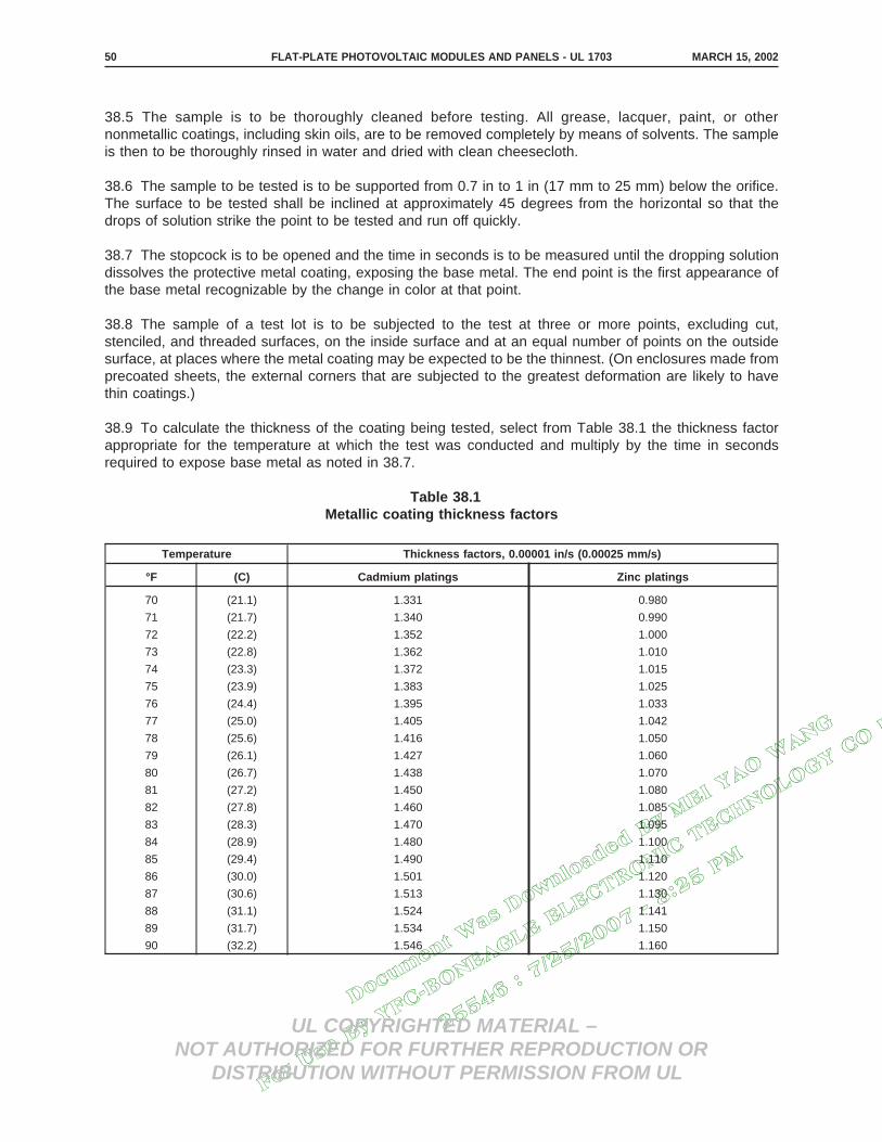
Docum
ent W
as D
ownlo
aded
By M
EI YAO W
ANG
For U
se B
y YFC
-BONEAGLE E
LECTRONIC T
ECHNOLOGY CO L
TD
25546 : 7/25/2007 -
8:25 P
M
UL COPYRIGHTED MATERIAL –NOT AUTHORIZED FOR FURTHER REPRODUCTION OR
DISTRIBUTION WITHOUT PERMISSION FROM UL
38.5 The sample is to be thoroughly cleaned before testing. All grease, lacquer, paint, or othernonmetallic coatings, including skin oils, are to be removed completely by means of solvents. The sampleis then to be thoroughly rinsed in water and dried with clean cheesecloth.
38.6 The sample to be tested is to be supported from 0.7 in to 1 in (17 mm to 25 mm) below the orifice.The surface to be tested shall be inclined at approximately 45 degrees from the horizontal so that thedrops of solution strike the point to be tested and run off quickly.
38.7 The stopcock is to be opened and the time in seconds is to be measured until the dropping solutiondissolves the protective metal coating, exposing the base metal. The end point is the first appearance ofthe base metal recognizable by the change in color at that point.
38.8 The sample of a test lot is to be subjected to the test at three or more points, excluding cut,stenciled, and threaded surfaces, on the inside surface and at an equal number of points on the outsidesurface, at places where the metal coating may be expected to be the thinnest. (On enclosures made fromprecoated sheets, the external corners that are subjected to the greatest deformation are likely to havethin coatings.)
38.9 To calculate the thickness of the coating being tested, select from Table 38.1 the thickness factorappropriate for the temperature at which the test was conducted and multiply by the time in secondsrequired to expose base metal as noted in 38.7.
Table 38.1Metallic coating thickness factors
Temperature Thickness factors, 0.00001 in/s (0.00025 mm/s)
°F (C) Cadmium platings Zinc platings
70 (21.1) 1.331 0.980
71 (21.7) 1.340 0.990
72 (22.2) 1.352 1.000
73 (22.8) 1.362 1.010
74 (23.3) 1.372 1.015
75 (23.9) 1.383 1.025
76 (24.4) 1.395 1.033
77 (25.0) 1.405 1.042
78 (25.6) 1.416 1.050
79 (26.1) 1.427 1.060
80 (26.7) 1.438 1.070
81 (27.2) 1.450 1.080
82 (27.8) 1.460 1.085
83 (28.3) 1.470 1.095
84 (28.9) 1.480 1.100
85 (29.4) 1.490 1.110
86 (30.0) 1.501 1.120
87 (30.6) 1.513 1.130
88 (31.1) 1.524 1.141
89 (31.7) 1.534 1.150
90 (32.2) 1.546 1.160
MARCH 15, 2002FLAT-PLATE PHOTOVOLTAIC MODULES AND PANELS - UL 170350

Docum
ent W
as D
ownlo
aded
By M
EI YAO W
ANG
For U
se B
y YFC
-BONEAGLE E
LECTRONIC T
ECHNOLOGY CO L
TD
25546 : 7/25/2007 -
8:25 P
M
UL COPYRIGHTED MATERIAL –NOT AUTHORIZED FOR FURTHER REPRODUCTION OR
DISTRIBUTION WITHOUT PERMISSION FROM UL
39 Hot-Spot Endurance Test
39.1 General
39.1.1 Each representative cell of a module or panel shall be subjected to simulated reverse voltagehot-spot heating conditions for 100 h, intermittently, as described in 39.1.2 – 39.9.8. The test shall notresult in:
a) The accessibility of parts involving a risk of electric shock;
b) Melting of solder; or
c) Any other indication of a risk of fire or electric shock.
39.1.2 The reverse voltage hot-spot heating condition specified in 39.1.1 occurs when a module isoperating at current levels that exceed the reduced short-circuit current capability of an individual cell orgroup of cells in an array circuit. This reduced short-circuit current capability can be the result of a varietyof causes including nonuniform illumination of the module (local shadowing), individual cell degradationdue to cracking, or loss of a portion of a series-parallel circuit due to individual interconnect open circuits.A module can operate at current levels exceeding its reduced short-circuit current capability duringuncontrolled or deliberate fault conditions such as a short circuit deliberately placed on the module forservicing or to otherwise disable the array. During a reverse voltage hot-spot heating condition, power isdissipated in the overcurrented cell or cells at a level equal to the product of the current and the reversevoltage that develops across the cell or cells. This can heat the cell or cells to elevated temperatures.
39.1.3 The procedure for conducting this test is as follows:
a) Selection and connection of power sources and instruments to appropriate cells for testing,
b) Determination of the hot-spot test levels, and
c) Conduction of the hot-spot endurance test.
39.2 Cell selection and instrumentation
39.2.1 The degree of hot-spot heating within an affected cell is dependent upon, in part, thereverse-voltage current-voltage (I-V) characteristics of the affected cell. The reverse-voltage I-Vcharacteristics may vary considerably from cell-to-cell within a given module. Accordingly, the range of thedark reverse-voltage I-V curves for a representative sample of cells (at least ten) within the test moduleare to be determined in accordance with 39.2.2 – 39.5.5. This can be done by directly accessing individualcells (intrusive method), or by shadowing technique (nonintrusive method) if the module is a simple seriesstring of cells. The intrusive-nonintrusive option relates to cell selection only. All cells subjected to hot-spotendurance shall be individually accessed.
39.2.2 The dark, reverse-voltage current-to-voltage (I-V) curves for not less than ten cells within themodule, modules, or panel, are to be determined using one of the following equations for reverse voltagesfrom 0 (zero) to the maximum voltage limit (VL) or currents from 0 (zero) to the maximum current limit (IL),whichever limit is reached first:
IL = ISC, or
MARCH 15, 2002 FLAT-PLATE PHOTOVOLTAIC MODULES AND PANELS - UL 1703 51

Docum
ent W
as D
ownlo
aded
By M
EI YAO W
ANG
For U
se B
y YFC
-BONEAGLE E
LECTRONIC T
ECHNOLOGY CO L
TD
25546 : 7/25/2007 -
8:25 P
M
UL COPYRIGHTED MATERIAL –NOT AUTHORIZED FOR FURTHER REPRODUCTION OR
DISTRIBUTION WITHOUT PERMISSION FROM UL
VL = N × Vmp.
In which:
ISC is the short-circuit current of an average cell at 100 mW/cm2, NOCT.
N is the number of series cells per bypass diode:
a) As an integral part of the module or panel, or
b) As is described for use with the module or panel in a marking affixed to the moduleor panel whichever is less. See 47.9.
Vmp is the average maximum power voltage of an average cell at 100 mW/cm2, NOCT.
When no bypass diode information is provided, N shall be equal to the number of series cells.
39.3 Intrusive method
39.3.1 With reference to 39.2.2, for the determination of cell I-V characteristics by the intrusive method,each cell tested is to be provided with individual positive and negative electrical leads to allow it to beaccessed independently of other cells.
39.3.2 The reverse voltage I-V curves of the tested cells are to be plotted. See 39.3.3. The cells are tobe identified as Type A (voltage limited) or Type B (current limited). A graph similar to Figure 39.1 shouldbe obtained.
This is generated text for figtxt.
MARCH 15, 2002FLAT-PLATE PHOTOVOLTAIC MODULES AND PANELS - UL 170352
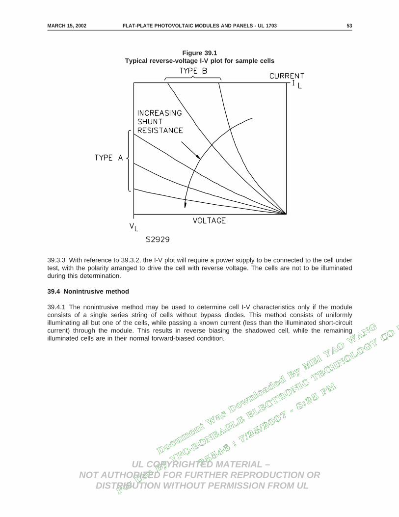
Docum
ent W
as D
ownlo
aded
By M
EI YAO W
ANG
For U
se B
y YFC
-BONEAGLE E
LECTRONIC T
ECHNOLOGY CO L
TD
25546 : 7/25/2007 -
8:25 P
M
UL COPYRIGHTED MATERIAL –NOT AUTHORIZED FOR FURTHER REPRODUCTION OR
DISTRIBUTION WITHOUT PERMISSION FROM UL
39.3.3 With reference to 39.3.2, the I-V plot will require a power supply to be connected to the cell undertest, with the polarity arranged to drive the cell with reverse voltage. The cells are not to be illuminatedduring this determination.
39.4 Nonintrusive method
39.4.1 The nonintrusive method may be used to determine cell I-V characteristics only if the moduleconsists of a single series string of cells without bypass diodes. This method consists of uniformlyilluminating all but one of the cells, while passing a known current (less than the illuminated short-circuitcurrent) through the module. This results in reverse biasing the shadowed cell, while the remainingilluminated cells are in their normal forward-biased condition.
Figure 39.1Typical reverse-voltage I-V plot for sample cells
MARCH 15, 2002 FLAT-PLATE PHOTOVOLTAIC MODULES AND PANELS - UL 1703 53

Docum
ent W
as D
ownlo
aded
By M
EI YAO W
ANG
For U
se B
y YFC
-BONEAGLE E
LECTRONIC T
ECHNOLOGY CO L
TD
25546 : 7/25/2007 -
8:25 P
M
UL COPYRIGHTED MATERIAL –NOT AUTHORIZED FOR FURTHER REPRODUCTION OR
DISTRIBUTION WITHOUT PERMISSION FROM UL
39.5 Theory and method of cell selection
39.5.1 For example, at the particular known current level, A in Figure 39.2, the output voltage at themodule terminals (Vo) under the condition of one cell shadowed will be the normal output voltage of themodule with all cells illuminated (Vam), less the voltage of one cell (Vc), less the reverse voltage of theshadowed cell (Vr), that is:
Vo = Vam − Vc − Vr
The module’s normal output voltage and voltage of one cell, both at a particular current level are fixed.The reverse voltage of a cell at a particular current level is variable, cell-to-cell, being higher for highershunt resistances. Thus, shadowing of the highest shunt resistance cell will result in lowest module outputvoltage, and shadowing of the lowest shunt resistance cell will result in the highest module voltage.
This is generated text for figtxt.
39.5.2 To determine the relative cell I-V characteristics by the nonintrusive method, the module is to beconnected to a variable resistor so that the output current may be maintained at a fixed level underconditions of shadowing any one cell (same current regardless of which cell is shadowed). The module isto be illuminated under a source which can illuminate all cells at a repeatable and uniform intensity. Themodule temperature is to be monitored and is to remain constant. Normally these conditions can beachieved by outdoor testing under sunlight.
Figure 39.2Module and cell characteristics – shadowed cells
MARCH 15, 2002FLAT-PLATE PHOTOVOLTAIC MODULES AND PANELS - UL 170354

Docum
ent W
as D
ownlo
aded
By M
EI YAO W
ANG
For U
se B
y YFC
-BONEAGLE E
LECTRONIC T
ECHNOLOGY CO L
TD
25546 : 7/25/2007 -
8:25 P
M
UL COPYRIGHTED MATERIAL –NOT AUTHORIZED FOR FURTHER REPRODUCTION OR
DISTRIBUTION WITHOUT PERMISSION FROM UL
39.5.3 With the module connected and illuminated as described in 39.5.2, each cell in turn is to beshadowed, the resistor is to be adjusted to maintain the current at the preselected fixed value, and theoutput voltage of the module measured. The cell that is shadowed when the output voltage is maximumis the cell with minimum shunt resistance, and the cell that is the shadowed when the output voltage isminimum is the cell with maximum shunt resistance. Intermediate shunt resistance cells will haveintermediate module voltage outputs.
39.5.4 The nonintrusive method is relative only, and in the manner presented does not provide anumerical value of any of the resistances. The cells of a module may be all voltage limited (high shuntresistance, Type A), all current limited (low shunt resistance, Type B), or a combination of both – see39.3.2. In general, the cells associated with the highest hot-spot heating levels are those with the highestshunt resistance, although low shunt resistance may be associated with highly localized heating.
39.5.5 Three nonadjacent individual cells within the test module or panel are to be selected: onerepresentative of the highest shunt resistance obtained, one representative of the average, and onerepresentative of the lowest. Each cell to be tested is to be provided with individual positive and negativeelectrical leads to allow the cells to be connected individually and directly to separate power supplies.Parallel current paths around the cells to be tested are to be eliminated by disrupting cell-to-cellconnections as necessary. The lead attachment should minimize disruption of the heat transfercharacteristics of the cell or the hot-spot endurance of the encapsulant system.
39.6 Selection of hot-spot test level
39.6.1 The objective of this portion of the test procedure is to select the level of heating and thecorresponding test condition that will stress the module or panel in a manner similar to a severe hot-spotfield condition. The severity of the field condition will depend on the array circuit configuration, the arrayI-V operating point, the ambient thermal conditions, the overall irradiance level, and the previouslydescribed characteristics of the affected cells. When a module is incorporated into a photovoltaic sourcecircuit, the maximum reverse voltage imposed on an individual cell can approach the system voltageunless bypass diodes are properly used. VL is set to yield the maximum reverse voltage that can beapplied across a single cell when the module is applied in a circuit with the minimum number of bypassdiodes as specified by its marking.
39.6.2 Thermocouples are to be affixed to the cell insulation system. See 19.11 and 19.12.
39.6.3 In 39.7.1 – 39.8.1, the detailed levels are separately specified for Type A and Type B cells.
39.6.4 The test is to be conducted in an ambient air temperature of 20 ±5°C (68 ±9°F) and with a radiantheating source that will result in a uniform background module cell temperature equal to NOCT ±2°C(±4°F).
MARCH 15, 2002 FLAT-PLATE PHOTOVOLTAIC MODULES AND PANELS - UL 1703 55

Docum
ent W
as D
ownlo
aded
By M
EI YAO W
ANG
For U
se B
y YFC
-BONEAGLE E
LECTRONIC T
ECHNOLOGY CO L
TD
25546 : 7/25/2007 -
8:25 P
M
UL COPYRIGHTED MATERIAL –NOT AUTHORIZED FOR FURTHER REPRODUCTION OR
DISTRIBUTION WITHOUT PERMISSION FROM UL
39.7 Type A cells (high shunt resistance)
39.7.1 The governing parameters concerning reverse voltage heating are:
a) The maximum cell reverse voltage (VL),
b) The cell irradiance level, and
c) The ambient thermal environment.
39.7.2 VL is to be set equal to N times the Vmp of an individual cell, where N is the number of series cellsper specified or integral bypass diode.
39.7.3 The irradiance level directly controls the hot-spot current level, and therefore the power level. Asillustrated in Figure 39.3, there is a unique irradiance level that corresponds to worst-case powerdissipation for any particular Type A photovoltaic cell. The irradiance level on the test cell is to be adjustedto achieve this worst case power dissipation with the current adjusted to ITEST, where ITEST = themaximum power current of the cell at 100 mW/cm2, NOCT.
39.8 Type B cells (low shunt resistance)
39.8.1 The cell shunt resistance of a Type B cell is so low that the maximum reverse voltage is set by theI-R drop across the cell. Worst-case heating occurs when the test cell is totally shadowed, and the currentlevel is at a maximum. Accordingly, the irradiance is not to be more than 5 mW/cm2. This irradiance levelallows for room lighting and an IR heating source. The current (IL) is to be equal to the short-circuit currentof an average cell at 100 mW/cm2, NOCT.
39.9 Test execution
39.9.1 The three selected test cells are to be subjected to cyclic hot-spot heating at the level determinedin accordance with 39.7.3 or 39.8.1 for a period of 100 h total on-time as specified in 39.9.2 – 39.9.6.
39.9.2 A constant voltage power supply (for Type A cells) and a constant current power supply (for TypeB cells) is to be connected to the cell under test, with the polarity arranged to drive the cells with reversevoltage. The voltage is to be adjusted to VL, and then the current is to be adjusted to ITEST (for Type Acells) or IL (for Type B cells). See 39.7.2 – 39.8.1.
39.9.3 An infrared radiant heating source with a visible light contribution below 5 mW/cm2 is to be appliedto the module or panel and adjusted to result in a uniform module cell temperature equal to NOCT ±2°C(±4°F). The ambient air is to be still and at a temperature of 20 ±5°C (68 ±9°F).
This is generated text for figtxt.
MARCH 15, 2002FLAT-PLATE PHOTOVOLTAIC MODULES AND PANELS - UL 170356

Docum
ent W
as D
ownlo
aded
By M
EI YAO W
ANG
For U
se B
y YFC
-BONEAGLE E
LECTRONIC T
ECHNOLOGY CO L
TD
25546 : 7/25/2007 -
8:25 P
M
UL COPYRIGHTED MATERIAL –NOT AUTHORIZED FOR FURTHER REPRODUCTION OR
DISTRIBUTION WITHOUT PERMISSION FROM UL
39.9.4 For a Type A cell, an additional light source is to be used to illuminate each test cell to the leveldetermined in 39.7.3 (Figure 39.3). The illumination is most easily accomplished after the power supplyand IR source are turned on by adjusting the irradiance level to achieve the ITEST current after equilibriumtest conditions stabilize.
39.9.5 The power supply, IR source, and irradiance source are to be energized for 1 h followed by anoff-period sufficient to allow the cells under test to cool to within 10°C (18°F) of the ambient temperature.
39.9.6 The operation is to be repeated until a total of 100 h of on-time have been accumulated.
39.9.7 the test cells and the adjacent areas of the encapsulation system are to be visually inspected at24-h intervals during the test while the cells are under impressed voltage conditions and also uponcompletion of the 100 h of on-time operation.
39.9.8 At the conclusion of the test, the module is to be inspected for visible signs of melted solder,openings in the enclosure, delamination, and burn spots on the substrate.
Figure 39.3Effect of test-cell illumination level on hot-spot power dissipation
MARCH 15, 2002 FLAT-PLATE PHOTOVOLTAIC MODULES AND PANELS - UL 1703 57

Docum
ent W
as D
ownlo
aded
By M
EI YAO W
ANG
For U
se B
y YFC
-BONEAGLE E
LECTRONIC T
ECHNOLOGY CO L
TD
25546 : 7/25/2007 -
8:25 P
M
UL COPYRIGHTED MATERIAL –NOT AUTHORIZED FOR FURTHER REPRODUCTION OR
DISTRIBUTION WITHOUT PERMISSION FROM UL
40 Arcing Test
40.1 General
40.1.1 If the point of current (at rated operating voltage) and voltage (VL as determined from therelationship given in 39.2.2) that can appear across a cell or interconnect fracture is in the ″ARC TEST″zone in Figure 40.1, the module or panel shall comply with the provisions of 40.1.2 – 40.6.3. See also47.9.This is generated text for figtxt.
MARCH 15, 2002FLAT-PLATE PHOTOVOLTAIC MODULES AND PANELS - UL 170358

Docum
ent W
as D
ownlo
aded
By M
EI YAO W
ANG
For U
se B
y YFC
-BONEAGLE E
LECTRONIC T
ECHNOLOGY CO L
TD
25546 : 7/25/2007 -
8:25 P
M
UL COPYRIGHTED MATERIAL –NOT AUTHORIZED FOR FURTHER REPRODUCTION OR
DISTRIBUTION WITHOUT PERMISSION FROM UL
Figure 40.1Currents and voltages for arc test
MARCH 15, 2002 FLAT-PLATE PHOTOVOLTAIC MODULES AND PANELS - UL 1703 59

Docum
ent W
as D
ownlo
aded
By M
EI YAO W
ANG
For U
se B
y YFC
-BONEAGLE E
LECTRONIC T
ECHNOLOGY CO L
TD
25546 : 7/25/2007 -
8:25 P
M
UL COPYRIGHTED MATERIAL –NOT AUTHORIZED FOR FURTHER REPRODUCTION OR
DISTRIBUTION WITHOUT PERMISSION FROM UL
40.1.2 With reference to 40.1.1, during conditions of simulated cell or interconnect fracture, there shall beno ignition of the module or panel.
40.2 Method A
40.2.1 Similar modules or panels to be tested are to be connected in series to achieve an open-circuitvoltage across the fracture equal to that which is present during normal use of the modules or panels withthe specified bypass diodes. The modules and panels are to be irradiated at 80 mW/cm2 or more at 20 –30°C (68 – 86°F).
40.3 Method B
40.3.1 A single module or panel is to be used with a separate power supply as described in 40.5.2connected in series to provide the remainder of the source. The module or panel under test is to beirradiated at 80 mW/cm2 or more at 20°C – 30°C (68°F – 86°F).
40.4 Methods A and B
40.4.1 All bypass diodes, either included with the module or panel or described in the markings shall beincluded in the test circuit.
40.5 Method C
40.5.1 A single module or panel is to be used to provide the material for the ignition attempt. However,all power in the arc is to be provided by an external power supply as described in 40.5.2 connected inseries with only passive portions of the module’s circuit. Cells are to be jumpered if necessary to involvespecific portions of the module or panel insulation system.
40.5.2 With reference to 40.3.1 and 40.5.1 the power supply is to be a constant voltage supply with aseries connected current-limiting resistor. The parameters of the total system are to be as follows:
a) Open-Circuit Voltage – The voltage that is across the fracture during normal use of themodules or panels with the specified bypass diodes.
b) Short-Circuit Current – Not less than 80 percent nor more than the rated module or panelshort-circuit current, when the current-limiting resistor is adjusted so that the voltage across themodule or panel being tested is zero.
MARCH 15, 2002FLAT-PLATE PHOTOVOLTAIC MODULES AND PANELS - UL 170360

Docum
ent W
as D
ownlo
aded
By M
EI YAO W
ANG
For U
se B
y YFC
-BONEAGLE E
LECTRONIC T
ECHNOLOGY CO L
TD
25546 : 7/25/2007 -
8:25 P
M
UL COPYRIGHTED MATERIAL –NOT AUTHORIZED FOR FURTHER REPRODUCTION OR
DISTRIBUTION WITHOUT PERMISSION FROM UL
40.6 All methods
40.6.1 The system load is to be a short circuit.
40.6.2 Any connection(s) within the module or panel may be broken (fractured). The breaks are to bechosen to achieve a worst case condition of maximum open-circuit voltage and/or maximum short-circuitcurrent at one of the chosen break points.
Exception: Any electrical connection made with wire of circular cross section or flexible braidedconstruction that is mechanically secured to its connection points is not to be broken. Braided or strandedwire shall not have any process performed on it that reduces its flexibility. Solder coating of a portion ofthe wire at the connection points is acceptable.
40.6.3 An arc is to be drawn across the breaks, with the arc across the material of the module or panelthat it might contact during use of the module or panel. The arcing is to be continued for 15 min at eachlocation tested.
41 Mechanical Loading Test
41.1 A module or panel and any mounting hardware supplied with the module or panel shall withstand aload as shown in Figure 41.1 and specified in 41.2 for a period of 30 min, without evidence of structuralor mechanical failure. Modules that are intended to be installed as part of a building wall or roof structure,and serve as primary members of that structure, shall not have a deflection of more than L/240; where″L″ is equal to the clear span length in feet of the deflected member. All glazing materials shall be of suchstrength as to withstand the loads specified in 41.2.
41.2 The design load is to be 30 lb/ft2 (146.5 kg/m2) positive (downward) or negative (upward); or adesign load designated by the manufacturer, whichever is greater. A load of 1.5 times the design loadshall be applied for all tests other than the negative (upward) load on the above-roof mountingconfiguration, as noted in Figure 41.1. The downward and upward loads shall not be appliedsimultaneously.
This is generated text for figtxt.
MARCH 15, 2002 FLAT-PLATE PHOTOVOLTAIC MODULES AND PANELS - UL 1703 61

Docum
ent W
as D
ownlo
aded
By M
EI YAO W
ANG
For U
se B
y YFC
-BONEAGLE E
LECTRONIC T
ECHNOLOGY CO L
TD
25546 : 7/25/2007 -
8:25 P
M
UL COPYRIGHTED MATERIAL –NOT AUTHORIZED FOR FURTHER REPRODUCTION OR
DISTRIBUTION WITHOUT PERMISSION FROM UL
Figure 41.1Load application
NOTE: (X) The basic load distribution factors for this mounting configuration are 0.5 for the suction load and 0.8 for the uplift load.
These factors multiplied by 1.5 result in the indicated factors of 0.75 and 1.2.
MARCH 15, 2002FLAT-PLATE PHOTOVOLTAIC MODULES AND PANELS - UL 170362

Docum
ent W
as D
ownlo
aded
By M
EI YAO W
ANG
For U
se B
y YFC
-BONEAGLE E
LECTRONIC T
ECHNOLOGY CO L
TD
25546 : 7/25/2007 -
8:25 P
M
UL COPYRIGHTED MATERIAL –NOT AUTHORIZED FOR FURTHER REPRODUCTION OR
DISTRIBUTION WITHOUT PERMISSION FROM UL
42 Wiring Compartment Securement Test
42.1 The tensile force required to separate a wiring compartment or box from a module shall not be lessthan 35 lbf (155.7 N) or 4 times the wiring compartment or box weight, whichever is greater, when testedas specified in 42.2 and 42.3. For a test in which the superstrate or substrate fails prior to the adhesive,the force required to cause the superstrate or substrate to fail shall be used to determine compliance, andshall not be less than the specified minimum separation force.
42.2 Seven assemblies consisting of a wiring compartment or box secured to a module with adhesive asintended are to be tested. One assembly is to be tested in the as-received condition, three after beingconditioned in accordance with Temperature Cycling Test, Section 35, and three after conditioning inaccordance with Humidity Test, Section 36.
42.3 The force is to be applied to each assembly so as to separate the wiring compartment or box fromthe module. The force is to be applied until the wiring compartment or box and the module separates; orthe superstrate or substrate fails.
PRODUCTION LINE TESTS
43 Factory Dielectric Voltage-Withstand Test
43.1 Each module or panel shall withstand for 1 min without electrical breakdown as a routine productionline test, the application of a dc test potential as specified in 43.2, between parts involving a risk of electricshock and accessible metal parts.
Exception No. 1: The test period may be reduced to 1 s if the test potential is increased to 120 percentof the value specified in 43.2.
Exception No. 2: A module or panel with a system voltage rating of 30 V or less need not be tested.
43.2 The dc test potential shall be 2V + 1000 V, where ″V″ is the rated maximum acceptable systemvoltage.
43.3 The test equipment is to include a means of indicating the test voltage that is being applied to theproduct under test. This may be accomplished by sensing the voltage at the test leads or by an equivalentmeans. The test equipment is also to include a means of effectively indicating unacceptable performance.The indication is to be:
a) Audible, if it can be readily heard above the background noise level;
b) Visual, if it commands the attention of the operator; or
c) A device that automatically rejects an unacceptable product. If the indication of unacceptableperformance is audible or visual, the indication is to remain active and conspicuous until the testequipment is manually reset.
MARCH 15, 2002 FLAT-PLATE PHOTOVOLTAIC MODULES AND PANELS - UL 1703 63

Docum
ent W
as D
ownlo
aded
By M
EI YAO W
ANG
For U
se B
y YFC
-BONEAGLE E
LECTRONIC T
ECHNOLOGY CO L
TD
25546 : 7/25/2007 -
8:25 P
M
UL COPYRIGHTED MATERIAL –NOT AUTHORIZED FOR FURTHER REPRODUCTION OR
DISTRIBUTION WITHOUT PERMISSION FROM UL
43.4 The test potential specified in 43.2 may be obtained from any convenient source having a capacityof at least 500 VA.
Exception: The capacity may be lower if the means of indicating the test voltage is located in the outputcircuit – to maintain the potential indicated in 43.2 except in case of breakdown. The voltage of the sourceis to be continuously adjustable.
43.5 The test equipment is to indicate unacceptable performance within 0.5 s if the leakage current at thetest voltage exceeds 50 µA.
43.6 The test is to be conducted when the module is complete and ready for packing, or when it iscomplete except for covers or other parts that may interfere with the performance of the test.
44 Factory Voltage, Current, and Power Measurements Test
44.1 The short-circuit current (ISC), maximum power (Pmax), and open-circuit voltage (VOC) of eachproduction module are to be measured in accordance with the appropriate test procedure (StandardMethods of Testing Electrical Performance of Nonconcentrator Terrestrial Photovoltaic Modules andArrays Using Reference Cells, ASTM E1036-85, or Photovoltaic Devices, Part 1: Measurement ofPhotovoltaic Current-Voltage Characteristics, IEC 904-1) and the results recorded at STC using theappropriate correction procedure. The recorded values of ISC, Pmax, and VOC shall be within the markedtolerance. See 48.2. The test procedures mentioned in 18.1 and 18.2 shall be applied.
Exception: See Supplement SA.
45 Grounding Continuity Test
45.1 Each module or panel provided with a connection for grounding accessible conductive parts shall besubjected to a routine production line test to demonstrate electrical continuity between the groundingconnection and all accessible conductive parts.
45.2 Any appropriate indicating device, such as an ohmmeter, a low-voltage battery and buzzercombination, or the like may be employed for the test described in 45.1.
RATING
46 Details
46.1 The electrical rating of a module or panel shall include the voltage, current and power ratingsspecified in Table 46.1.
MARCH 15, 2002FLAT-PLATE PHOTOVOLTAIC MODULES AND PANELS - UL 170364

Docum
ent W
as D
ownlo
aded
By M
EI YAO W
ANG
For U
se B
y YFC
-BONEAGLE E
LECTRONIC T
ECHNOLOGY CO L
TD
25546 : 7/25/2007 -
8:25 P
M
UL COPYRIGHTED MATERIAL –NOT AUTHORIZED FOR FURTHER REPRODUCTION OR
DISTRIBUTION WITHOUT PERMISSION FROM UL
Table 46.1Electrical ratings
Voltage Current Power
Open-circuit voltage Short-circuit current Maximum power
Operating voltage Current at rated operating voltage
Maximum system voltage
MARKING
47 Details
47.1 A module or panel shall have a plain, legible, permanent marking that includes:
a) The manufacturer’s name, trademark, or other descriptive marking by which the organizationresponsible for the product can be identified;
b) The model number or the equivalent;
c) The electrical rating – see 46.1; and
d) The date or other dating period of manufacture not exceeding any three consecutive months.
Exception No. 1: The manufacturer’s identification may be in a traceable code if the product is identifiedby the brand or trademark owned by a private labeler.
Exception No. 2: The date of manufacture may be abbreviated; or may be in a nationally acceptedconventional code or in a code affirmed by the manufacturer, provided that the code:
a) Does not repeat in less than 10 years; and
b) Does not require reference to the production records of the manufacturer to determine whenthe product was manufactured.
47.2 A permanent marking shall be molded, die-stamped, paint-stenciled, stamped, or etched metal thatis permanently secured, or indelibly stamped on a pressure-sensitive label secured by adhesive thatcomplies with the Standard for Marking and Labeling Systems, UL 969. Ordinary usage, handling,storage, and the like of the unit shall be considered in determining whether a marking is permanent.
47.3 If a module or panel is manufactured at more that one factory, it shall have a marking indicating itsplace of manufacture.
47.4 The output power wiring terminals, leads, connector, or other connection means of a module orpanel shall be identified with one of the following marking statements:
MARCH 15, 2002 FLAT-PLATE PHOTOVOLTAIC MODULES AND PANELS - UL 1703 65

Docum
ent W
as D
ownlo
aded
By M
EI YAO W
ANG
For U
se B
y YFC
-BONEAGLE E
LECTRONIC T
ECHNOLOGY CO L
TD
25546 : 7/25/2007 -
8:25 P
M
UL COPYRIGHTED MATERIAL –NOT AUTHORIZED FOR FURTHER REPRODUCTION OR
DISTRIBUTION WITHOUT PERMISSION FROM UL
″+″ and ″−″ or
″POS″ and ″NEG″ or
″POSITIVE″ and ″NEGATIVE″
47.5 During the temperature test, if the temperature on a field-installed lead or on any part of the wiringcompartment that the lead might contact is more than 60°C (140°F), the module or panel shall be markedwith one of the statements indicated in 47.5(a) or (b) or the equivalent. The marking shall be located ator near the points where field connections will be made, and located so that it will be readily visible duringinstallation.
a) ″For field connections, use No. ___ AWG wires insulated for a minimum of 75°C ″, or
b) ″For field connections, use No. ___ AWG wires insulated for a minimum of 90°C ″.
47.6 If the pressure wire connectors of a module or panel are not acceptable for use with aluminum wire,or if the module or panel manufacturer intends the use of only copper wire, the module or panel shall bemarked, at or adjacent to the terminals, with the statement ″Use copper wire only,″ ″CU only,″ or theequivalent. This marking may be combined with the marking required by 47.5.
47.7 If the pressure wire connectors of a module or panel are acceptable for accommodating both copperand aluminum wire and if the manufacturer intends such use, the module or panel shall be marked(independent of any marking of the terminal) with the statement ″Use aluminum or copper wire,″ ″AL-CU,″or the equivalent. This marking may be combined with the marking required by 47.5.
47.8 In accordance with 13.3.3, a module or panel employing a nonmetallic wiring compartment havinga threaded opening shall be marked ″For use with nonmetallic wiring systems only″ or the equivalent.
47.9 A module or panel shall be marked:
a) To indicate the minimum acceptable diode ratings and to indicate the configuration forbypassing, or
b) To make reference to a manufacturer’s literature where information on diode bypassing canbe found. The module or panel manufacturer shall supply this literature with the module orpanel.
Exception No. 1: Marking or literature is not required when the system DC voltage rating is equal to thelimit voltage (VL) used for the Hot-Spot Endurance Test and the Arcing Test. See 39.2.2 and 40.1.1,respectively.
Exception No. 2: A module or panel supplied with a bypass diode is not required to be marked when thetype, voltage rating, current rating, and configuration of the diode are identified in the installationinstructions.
47.10 A module or panel shall be marked relative to the maximum electrical rating of an acceptable seriesfuse (for protection against backfeed).
MARCH 15, 2002FLAT-PLATE PHOTOVOLTAIC MODULES AND PANELS - UL 170366

Docum
ent W
as D
ownlo
aded
By M
EI YAO W
ANG
For U
se B
y YFC
-BONEAGLE E
LECTRONIC T
ECHNOLOGY CO L
TD
25546 : 7/25/2007 -
8:25 P
M
UL COPYRIGHTED MATERIAL –NOT AUTHORIZED FOR FURTHER REPRODUCTION OR
DISTRIBUTION WITHOUT PERMISSION FROM UL
47.11 A module or panel shall be marked relative to its fire resistance rating as a roof covering. A moduleor panel shall be marked ″Not Fire Rated,″ unless it complies with the requirements for fire rating. If amodule or panel is fire rated and if its use is so intended by the manufacturer, it shall be markedaccordingly, for example, ″Modules mounted freestanding 6 in above a Class B roof constitute a Class Croof.″
47.12 A module provided as a part of a panel shall be provided with all of the markings that would berequired for its existence as a separate entity.
47.13 A module or panel intended for structural loads greater than 30 lb/ft2 (146.5 kg/m2) shall be markedwith the intended load in lb/ft2.
48 Installation and Assembly Instructions
48.1 A module or panel shall be supplied with installation instructions describing the methods of electricaland mechanical installation and the electrical ratings of the module or panel. When the fire rating isdependent on a specific mounting structure, specific spacings, or specific means of attachment to the roofor structure, details of the specific parameter or parameters shall be included in the instructions.
48.1.1 The electrical installation instructions shall include a detailed description of the wiring method tobe used in accordance with the National Electrical Code. This description shall include:
a) The grounding method to be used,
b) The size, type, and temperature rating of the conductors to be used,
c) The type of overcurrent protection to be used,
d) The minimum and maximum cable diameters when the wiring method is cable, and
e) Any limitations on wiring methods that apply to the wiring compartment or box.
48.1.2 The mechanical installation instructions for roof mounting shall include:
a) A statement indicating the minimum mechanical means to be used for securement of themodule or panel to the roof,
b) For a non-integral module or panel (See Figure 41.1 ), a statement that the assembly is tobe mounted over a fire resistant roof covering rated for the application, and
c) Indication of any slope less than 5 in/ft (127 mm/305 mm) required to maintain a fire Classrating.
48.2 The electrical ratings mentioned in 48.1 shall include information indicated in 48.1 and the followingstatement or the equivalent: ″The electrical characteristics are within ±10 percent of the indicated valuesof ISC, VOC, and Pmax under standard test conditions (irradiance of 100 mW/cm2, AM 1.5 spectrum, anda cell temperature of 25°C (77°F)). ″
Exception: The tolerance may be either smaller than ±10 percent or omitted, provided the valuesmeasured during the production line tests– see 44.1 – are:
a) Within a tolerance indicated in the instructions when a smaller tolerance is indicated, or
MARCH 15, 2002 FLAT-PLATE PHOTOVOLTAIC MODULES AND PANELS - UL 1703 67
Docum
ent W
as D
ownlo
aded
By M
EI YAO W
ANG
For U
se B
y YFC
-BONEAGLE E
LECTRONIC T
ECHNOLOGY CO L
TD
25546 : 7/25/2007 -
8:25 P
M
UL COPYRIGHTED MATERIAL –NOT AUTHORIZED FOR FURTHER REPRODUCTION OR
DISTRIBUTION WITHOUT PERMISSION FROM UL
b) The same as the values indicated in the instructions when the tolerance is omitted.
48.3 The installation instructions shall include a statement advising that artificially concentrated sunlightshall not be directed on the module or panel.
48.4 Assembly instructions shall be provided with a product shipped in subassemblies, and shall bedetailed and adequate to the degree required to facilitate total assembly of the product.
48.5 To allow for increased output of a module or panel resulting from certain conditions of use, theinstallation instructions for a module or panel containing crystalline-silicon cells shall include the followingstatement or the equivalent: ″Under normal conditions, a photovoltaic module is likely to experienceconditions that produce more current and/or voltage than reported at standard test conditions.Accordingly, the values of ISC and VOC marked on this module should be multiplied by a factor of 1.25when determining component voltage ratings, conductor ampacities, fuse sizes, and size of controlsconnected to the PV output.″ For a module or panel containing other than crystalline-silicon cells, themultiplying factor at conditions of an irradiance of 125 mW/cm2, AM 1.5 spectrum, and a cell temperatureof minus 10°C (plus 14°F) for VOC and plus 75°C (167°F) for ISC is to be determined and this factor is tobe indicated in the instructions.
48.6 To inform the installer that a multiplying factor in addition to that mentioned in 48.5 may beapplicable, the installation instructions shall include the following statement or the equivalent: ″Refer toSection 690-8 of the National Electrical Code for an additional multiplying factor of 125 percent (80percent derating) which may be applicable.″
MARCH 15, 2002FLAT-PLATE PHOTOVOLTAIC MODULES AND PANELS - UL 170368

Docum
ent W
as D
ownlo
aded
By M
EI YAO W
ANG
For U
se B
y YFC
-BONEAGLE E
LECTRONIC T
ECHNOLOGY CO L
TD
25546 : 7/25/2007 -
8:25 P
M
UL COPYRIGHTED MATERIAL –NOT AUTHORIZED FOR FURTHER REPRODUCTION OR
DISTRIBUTION WITHOUT PERMISSION FROM UL
SUPPLEMENT SA - SAMPLE PRODUCTION LINE TESTS
SA1 Scope
SA1.1 This supplement describes the tests that are to be conducted on samples of production modulesor panels.
SA2 Sample Size
SA2.1 An appropriate number of samples to be tested is to be determined by reviewing previouslyrecorded information on the production process capability.
SA2.2 If previously recorded information on the production process capability is not available, 100percent production line tests shall be conducted until a sufficient number of samples have demonstratedcompliance with specifications.
SA3 Factory Voltage, Current, and Power Measurements Test
SA3.1 The samples as specified in paragraph SA2.1 are to be subjected to the test specified in 41.1. Therecorded values of ISC, Pmax, and Voc shall be within the marked tolerance.
MARCH 15, 2002 FLAT-PLATE PHOTOVOLTAIC MODULES AND PANELS - UL 1703 SA1

Docum
ent W
as D
ownlo
aded
By M
EI YAO W
ANG
For U
se B
y YFC
-BONEAGLE E
LECTRONIC T
ECHNOLOGY CO L
TD
25546 : 7/25/2007 -
8:25 P
M
UL COPYRIGHTED MATERIAL –NOT AUTHORIZED FOR FURTHER REPRODUCTION OR
DISTRIBUTION WITHOUT PERMISSION FROM UL
MARCH 15, 2002FLAT-PLATE PHOTOVOLTAIC MODULES AND PANELS - UL 1703SA2
No Text on This Page

Docum
ent W
as D
ownlo
aded
By M
EI YAO W
ANG
For U
se B
y YFC
-BONEAGLE E
LECTRONIC T
ECHNOLOGY CO L
TD
25546 : 7/25/2007 -
8:25 P
M
UL COPYRIGHTED MATERIAL –NOT AUTHORIZED FOR FURTHER REPRODUCTION OR
DISTRIBUTION WITHOUT PERMISSION FROM UL
APPENDIX A
Standards for Components
Standards under which components of the products covered by this standard are evaluated include thefollowing:
Title of Standard − UL Standard Designation
Fuseholders – UL 512Insulating Materials – General, Systems of – UL 1446Marking and Labeling Systems – UL 969Outlet Boxes, Flush-Device Boxes and Covers, Nonmetallic – UL 514COutlet Boxes, Metallic – UL 514APlastic Materials for Parts in Devices and Appliances, Tests for Flammability of – UL 94Polymeric Materials – Fabricated Parts – UL 746DPolymeric Materials – Long Term Property Evaluations – UL 746BPolymeric Materials – Short Term Property Evaluations – UL 746APolymeric Materials – Use in Electrical Equipment Evaluations – UL 746CPrinted-Wiring Boards – UL 796Roof Covering Materials, Tests for Fire Resistance of – UL 790Sharpness of Edges on Equipment, Test for – UL 1439Terminals, Electrical Quick-Connect – UL 310Tubing, Extruded Insulating – UL 224Wire Connectors and Soldering Lugs for Use with Copper Conductors – UL 486AWire Connectors for Use with Aluminum Conductors – UL 486BWires and Cables, Thermoset-Insulated – UL 44Wires and Cables, Thermoplastic-Insulated – UL 83
MARCH 15, 2002 FLAT-PLATE PHOTOVOLTAIC MODULES AND PANELS - UL 1703 A1

Docum
ent W
as D
ownlo
aded
By M
EI YAO W
ANG
For U
se B
y YFC
-BONEAGLE E
LECTRONIC T
ECHNOLOGY CO L
TD
25546 : 7/25/2007 -
8:25 P
M
UL COPYRIGHTED MATERIAL –NOT AUTHORIZED FOR FURTHER REPRODUCTION OR
DISTRIBUTION WITHOUT PERMISSION FROM UL
MARCH 15, 2002FLAT-PLATE PHOTOVOLTAIC MODULES AND PANELS - UL 1703A2
No Text on This Page

Docum
ent W
as D
ownlo
aded
By M
EI YAO W
ANG
For U
se B
y YFC
-BONEAGLE E
LECTRONIC T
ECHNOLOGY CO L
TD
25546 : 7/25/2007 -
8:25 P
M
UL COPYRIGHTED MATERIAL –NOT AUTHORIZED FOR FURTHER REPRODUCTION OR
DISTRIBUTION WITHOUT PERMISSION FROM UL
CANADIAN REQUIREMENTS COMPARISON GUIDE, CRG 1703
UL AND CANADIAN STANDARDS FOR FLAT-PLATE PHOTOVOLTAIC MODULESAND PANELS
MARCH 15, 2002 FLAT-PLATE PHOTOVOLTAIC MODULES AND PANELS - CRG 1703 CRG1

Docum
ent W
as D
ownlo
aded
By M
EI YAO W
ANG
For U
se B
y YFC
-BONEAGLE E
LECTRONIC T
ECHNOLOGY CO L
TD
25546 : 7/25/2007 -
8:25 P
M
UL COPYRIGHTED MATERIAL –NOT AUTHORIZED FOR FURTHER REPRODUCTION OR
DISTRIBUTION WITHOUT PERMISSION FROM UL
Product Category: Flat-Plate Photovoltaic Modules and PanelsUL Category Control Numbers: QIGU7, QIGU8
UL Standard:Flat-Plate Photovoltaic Modules and PanelsUL 1703Third Edition
Canadian Standard:Flat-Plate Photovoltaic Modules and PanelsULC/ORD-C1703-01Second Edition
This Canadian Requirement Comparison Guide is only intended to identify Canadian requirements thatmust be applied in addition to the requirements in the UL Standard to obtain a C-UL Mark. The guide isnot intended to replace a thorough review and comparison of the requirements applicable to the productcategory as contained in the applicable UL and Canadian Standards. Where requirements are notspecifically addressed, compliance with the requirements in the UL Standard satisfy the requirements inthe Canadian Standard.
The actual requirements applied for a C-UL product investigation may differ from those identified in thisguide based on the specific features, characteristics, components, materials, or systems used in theproduct.
CRG: 1703Issue No.: 2Issue Date: March 15, 2002
Revisions of this guide will be made by issuing revised or additional pages bearing their date of issue. ACanadian Requirement Comparison Guide is current only if it incorporates the most recently adoptedrevisions, all of which are itemized on the transmittal notice that accompanies the latest set of revisionpages for the Guide.
The following outlines the requirements contained in Flat-Plate Photovoltaic Modules and Modules,ULC/ORD-C1703-01, that are in addition to the requirements in UL 1703 that must be met in order for aproduct to bear the appropriate UL Marking. UL provides a certification program for products that meetthe Canadian requirements. The C-UL Mark is the manufacturer’s assurance that products, as evaluatedby UL, continue to comply with the appropriate Canadian requirements.
Copyright © 1998, 2002 Underwriters Laboratories Inc.
MARCH 15, 2002FLAT-PLATE PHOTOVOLTAIC MODULES AND PANELS - CRG 1703CRG2

Docum
ent W
as D
ownlo
aded
By M
EI YAO W
ANG
For U
se B
y YFC
-BONEAGLE E
LECTRONIC T
ECHNOLOGY CO L
TD
25546 : 7/25/2007 -
8:25 P
M
UL COPYRIGHTED MATERIAL –NOT AUTHORIZED FOR FURTHER REPRODUCTION OR
DISTRIBUTION WITHOUT PERMISSION FROM UL
Requirements Topics ULC Clause Comparison
Marking 4.6.9 A terminal intended to accommodate an equipment-groundingconductor shall be identified by being marked ″G″ or ″ ″ orshall have a green-coloured part.
Marking 7.1.4 The output power wiring terminals, leads, connector, or otherconnection means of a module or panel shall be identified withthe following marking statements: ″+″ and ″-.″
Installation instructions 7.2.3 The electrical installation instructions shall include a statementthat installation shall be in accordance with CSA C22.1, SafetyStandard for Electrical Installations, Canadian Electrical Code,Part 1.
MARCH 15, 2002 FLAT-PLATE PHOTOVOLTAIC MODULES AND PANELS - CRG 1703 CRG3

Docum
ent W
as D
ownlo
aded
By M
EI YAO W
ANG
For U
se B
y YFC
-BONEAGLE E
LECTRONIC T
ECHNOLOGY CO L
TD
25546 : 7/25/2007 -
8:25 P
M
UL COPYRIGHTED MATERIAL –NOT AUTHORIZED FOR FURTHER REPRODUCTION OR
DISTRIBUTION WITHOUT PERMISSION FROM UL
MARCH 15, 2002FLAT-PLATE PHOTOVOLTAIC MODULES AND PANELS - CRG 1703CRG4
No Text on This Page


![LG Specshet Neon R 60 - s3. · PDF fileShort Circuit Current (Isc) [A] 10.80 10.79 10.78 10.77 Module Efficiency [%] 21.1 20.8 20.6 20.3 ... IEC 61215, IEC 61730-1/-2 UL 1703 IEC 61701](https://img.pdfslide.us/doc/110x75/5aa71d657f8b9ac5648bb0f9/lg-specshet-neon-r-60-s3-short-circuit-current-isc-a-1080-1079-1078.jpg)