Embed Size (px)
Citation preview
O & M MANUAL
OPERATING & MAINTENANCE INSTRUCTIONSSERVICE INSTRUCTIONSMAINTENANCE RECORDS
UK ROLLER SHUTTERS www.ukrollershutters.co.uk
O & M MANUAL
UK ROLLER SHUTTERS AND GARAGE DOORS LIMITED TEL: +44 (0) 1384 221 743 EMAIL: [email protected] WEB: www.ukrollershutters.co.uk
1
OPERATING & MAINTENANCE INSTRUCTIONS
SERVICE INSTRUCTIONS
MAINTENANCE RECORDS
UK ROLLER SHUTTERS www.ukrollershutters.co.uk
INTRODUCTION An industrial door is vital everyday piece of machinery in the operation of almost every industrial building. If a door is not maintained properly it can become extremely danger-ous and, if unusable, can even stop your business operations. To comply with Health & Safety regulations and to keep within our warranty it is imperative that the door be oper-ated and maintained in accordance with these instructions. Should you require any fur-ther information or assistance with this logbook, please do not hesitate to contact us.
These operating instructions must be passed to the owner of the door. They should be read and understood by all personnel who will be
operating the door.
UK ROLLER SHUTTERS AND GARAGE DOORS LIMITED TEL: +44 (0) 1384 221 743 EMAIL: [email protected] WEB: www.ukrollershutters.co.uk
2
CONTENTS Page 1: COVER SHEET Page 2: INTRODUCTION AND CONTENTS PAGE
*OPERATING INSTRUCTIONS START* Page 3: MANUALLY OPERATED ROLLER SHUTTER DOOR/INSULATED Page 4: HAND CHAIN OPERATED ROLLER SHUTTER/INSULATED Page 5: ELECTRICALLY OPERATED ROLLER SYSTEM Page 6: ELECTRICALLY OPERATED ROLLER SYSTEM.. CONT’D and ELECTRICALLY OPERATED ROLLER SHUTTER/INSULATED Page 7: ELECTRICALLY OPERATED ROLLER SHUTTER/INSULATED CONT'D Page 8: PUSH UP OPERATED INSULATED SECTIONAL OVERHEAD DOOR Page 9: HAND CHAIN OPERATED INSULATED SECTIONAL OVERHEAD DOOR Page 10: ELECTRICALLY OPERATED INSULATED SECTIONAL OVERHEAD DOOR Page 11: ELECTRICALLY OPERATED INSULATED SECTIONAL OVERHEAD DOOR CONT’D Page 12: ELECTRICALLY OPERATED GARAGE DOOR Page 13: FIRE STOPPER - PUSH UP OPERATED FIRE RESISTING ROLLER SHUTTER DOOR Page 14: FIRE STOPPER - TUBULAR MOTOR TYPE FIRE RESISTING ROLLER SHUTTER DOOR Page 15: FIRE STOPPER - CONTROLLED DESCENT FIRE RESISTING ROLLER SHUTTER DOOR Page 16: HIGH SPEED ROLL DOOR (INTERNAL) Page 17: HIGH SPEED ROLL DOOR (INTERNAL & EXTERNAL) Page 18: HIGH SPEED FOLDING DOOR (EXTERNAL) Page 19: HIGH SPEED FAST ACTION DOORS (INTERNAL & EXTERNAL)
*OPERATING INSTRUCTIONS END* Page 20: CLEANING METHODS Page 21-23: SERVICE & SAFETY Page 24-27: SERVICE SHEETS
UK ROLLER SHUTTERS www.ukrollershutters.co.uk
WARRANTY
All equipment manufactured or supplied by the Company is guaranteed against faulty materials and workmanship for a period of 12 months from the date of installation (or de-livery in the case of supply only). This warranty is subject to fair wear and tear and having been maintained to our recommendations.
OPERATING INSTRUCTIONS
MANUALLY OPERATED ROLLER SHUTTER DOOR/INSULATED These operating instructions apply to a roller shutter door which is push up, hand operated or self coiling. The door is counterbalanced by springs and should only be operated by competent personnel. Basic Operation - To Open or Close the Door Check the door is not locked in any way and that there are no obstructions that may prevent the door from opening/closing. DO NOT ATTEMPT TO OPERATE THE DOOR UNTIL ALL OBSTRUCTIONS HAVE BEEN REMOVED. The door shall be manually opened or closed either by lifting the handles on the bottom rail of the door from opened or closed either by lifting the handles on the bottom rail of the door or by operated pole supplied, as the height dictates. The door must be kept under control at all times and should not be allowed to free travel. A safety brake is fitted to one end of the barrel assembly at high level, which will activate if the down-ward speed of the door is excessive. If activated, the brake will automatically lock in place and prevent the door from closing. To release the brake, simply reopen the door. Please note that continued activations of the safety brake would substantially reduce its life expec-tancy. A locking device is usually supplied with the door, which will be placed on the side guides or in the centre of the bottom rail. If on the side guides, which will be placed on the side guides or in the centre of the bottom rail. If a bottom central lock is supplied, enter key into cylinder and rotate as far as possible until the locking bars retract from the side guides.
UK ROLLER SHUTTERS AND GARAGE DOORS LIMITED TEL: +44 (0) 1384 221 743 EMAIL: [email protected] WEB: www.ukrollershutters.co.uk
3
UK ROLLER SHUTTERS www.ukrollershutters.co.uk
OPERATING INSTRUCTIONS
HAND CHAIN OPERATED ROLLER SHUTTER/INSULATED These operating instructions apply to a Roller Shutter Door, which is operated via a con-tinuous haul chain. The door is counterbalanced by springs and should only be operated by competent personnel. The door should not be operated under sever windy conditions. Basic Operation – To Open or Close the Door Check the door is not locked in any way and that there are no obstructions that may pre-vent the door from opening/closing. DO NOT ATTEMPT TO OPERATE THE DOOR UNTIL ALL OBSTRUCTIONS HAVE BEEN REMOVED. Release the haul chain at the side of the door from its keep. Pull the chain in the required direction, always maintaining a steady speed and control. Never release the chain during operation. Once the door has reached its required position, place the haul chain back into its keep. The keep is supplied to accept a standard padlock so that the haul chain can be locked in place if required. A safety brake is fitted to the non-geared end of the barrel assembly at high level, which will activate if the downward speed of the door is excessive. If activated, the brake will automatically lock in place and prevent the door from closing. To release the brake, sim-ply reopen the door. Please note that continued activation of the safety brake would sub-stantially reduce its life expectancy.
UK ROLLER SHUTTERS AND GARAGE DOORS LIMITED TEL: +44 (0) 1384 221 743 EMAIL: [email protected] WEB: www.ukrollershutters.co.uk
4
UK ROLLER SHUTTERS www.ukrollershutters.co.uk
OPERATING INSTRUCTIONS
ELECTRICALLY OPERATED ROLLER SYSTEM These operating instructions apply to a Roller Shutter Door, which is operated via a flange of foot-mounted motor drive. The door is supplied with a Safe Drive operator, which incorporates an internal safety brake. The door should only be operated by trained personnel and should not be used in severe windy conditions. Basic Operation To Open the Door Check the door is not locked in any way and that there are no obstructions that may pre-vent the door from opening. DO NOT ATTEMPT TO OPERATE THE DOOR UNTIL ALL OBSTRUCTIONS HAVE BEEN REMOVED. Apply continued pressure to the “UP” button, positioned at the side of the door and the door will travel vertically until it reaches its upper limit switch. At this point the control cir-cuit will open and the brake will engage to stop the door at its fully open position. If at any point the button is released, the door will stop at its current position. To restart the open operation, simply press the “UP” button again. If an additional means of safety is supplied with the door, such as a photoelectric safety beam, then continued pressure would not be required on the button. If at any time you need to stop the door, simply press the red emergency “STOP” button. If a key switch is supplied in lieu of push buttons, enter key into cylinder and turn towards “UP” to activate the door. The key switch will require contin-ued pressure, as it is spring loaded to its “OFF” position. To Close the Door Check the door is not locked in any way and that there are no obstructions that may pre-vent the door from closing. Check that the area is clear of all personnel. DO NOT ATTEMPT TO OPERATE THE DOOR UNTIL ALL OBSTRUCTIONS HAVE BEEN REMOVED. Apply continued pressure to the “DOWN” button, positioned at the side of the door and the door will travel vertically until it reaches its lower limit switch. At this point the control circuit will open and the brake will engage to stop the door at its fully closed position. If at any point the button is released, the door will stop at its current position. To restart the close operation, simply press the “DOWN” button again. If an additional means of safety is supplied with the door, such as a safety edge or photoelectric safety beam, then contin-ued pressure will not be required on the button. If at any time you need to stop the door, simply press the red emergency “STOP” button. If a key switch is supplied in lieu of push buttons, enter key into cylinder and turn towards “DOWN” to activate the door. The key switch will require continued pressure, as it is spring loaded to its “OFF” position.
UK ROLLER SHUTTERS AND GARAGE DOORS LIMITED TEL: +44 (0) 1384 221 743 EMAIL: [email protected] WEB: www.ukrollershutters.co.uk
5
ELECTRICALLY OPERATED ROLLER SYSTEM.. CONT’D
Emergency Manual Override Operation In the event of a power failure, the door is supplied with a manual over ride system. This is via a continuous haul chain and should only be used in emergencies. PLEASE NOTE that the emergency manual over ride system is not designed for every day use and that excessive use will cause premature failure. To engage the manual over ride system, simply pull on the green toggle at the side of the opening that is marked “MANUAL/HAND”. This will isolate the electrical control buttons and will engage the haul chain. Remove the haul chain from its keep and pull the haul chain in t he required direction. To disengage the manual over ride system, return the haul chain to its keep and pull on the red toggle at the side of the opening that is marked “MOT OR”. This will reinstate the electrical control buttons and will disengage the haul chain. The emergency manual over ride system cannot be used if the safety brake has been activated The SAFE DRIVE motor operator, which drives the door, is fitted with an internal safety brake. This is to prevent uncontrolled dropping of the door curtain. If a problem occurs that would cause the safety brake to engage the door will be locked in its position and the electrics to the motor will be open circuited. Once activated, the safe drive will have to be replaced. A qualified door engineer must only carry this out.
UK ROLLER SHUTTERS www.ukrollershutters.co.uk
OPERATING INSTRUCTIONS
Automatic Operation Where a door control system is fitted, such as timed return, radio control, induction loop activation, additional safety features will be installed on the door to give the required protection. Please refer to the automation section in the instructions.
ELECTRICALLY OPERATED ROLLER SHUTTER/INSULATED Application These operating instructions apply to a Roller Shutter Door, which is operated via a tubular mo-tor drive mounted within the barrel assembly. Basic Operation To Open the Door Check the door is not locked in any way and that there are no obstructions that may prevent the door from opening. DO NOT ATTEMPT TO OPERATE THE DOOR UNTIL ALL OBSTRUCTIONS HAVE BEEN REMOVED. Apply continued pressure to the “UP” button, positioned at the side of the door and the door will travel vertically until it reaches its upper limit switch. At this point the control circuit will open and the brake will engage to stop the door at its fully open position. If at any point the button is re-leased, the door will stop at its current position... CONT’D
UK ROLLER SHUTTERS AND GARAGE DOORS LIMITED TEL: +44 (0) 1384 221 743 EMAIL: [email protected] WEB: www.ukrollershutters.co.uk
6
UK ROLLER SHUTTERS www.ukrollershutters.co.uk
OPERATING INSTRUCTIONS
...To restart the open operation, simply press the “UP” button again. If an additional means of safety is supplied with the door, such as a photoelectric safety beam, then con-tinued pressure would not be required on the button. If at any time you need to stop the door, simply press the red emergency “STOP” button. If a key switch is supplied in lieu of push buttons, enter key into cylinder and turn towards “UP” to activate the door. The key switch will require continued pressure, as it is spring loaded to its “OFF” position. To Close the Door Check the door is not locked in any way and that there are no obstructions that may prevent the door from closing. Check that the area is clear of all personnel. DO NOT ATTEMPT TO OPERATE THE DOOR UNTIL ALL OBSTRUCTIONS HAVE BEEN REMOVED. Apply continued pressure to the “DOWN” button, positioned at the side of the door and the door will travel vertically until it reaches its lower limit switch. At this point the control circuit will open and the brake will engage to stop the door at its fully closed position. If at any point the button is released, the door will stop at its current position. To restart the close operation, simply press the “DOWN” button again. If an additional means of safety is supplied with the door, such as a safety edge or photoelectric safety beam, then continued pressure will not be required on the button. If at any time you need to stop the door, simply press the red emergency “STOP” button. If a key switch is supplied in lieu of push buttons, enter key into cylinder and turn towards “DOWN” to activate the door. The key switch will require continued pressure, as it is spring loaded to its “OFF” position. A Safety brake is fitted to the non-motor end of the barrel assembly at high level. This is to prevent uncontrolled dropping of the door curtain. If a problem occurs that would cause the safety brake to engage, the door will be locked in its position and the electrics to the motor will be open circuited. To release the brake, simply reopen the door. Please note that continued activation of the safety brake would substantially reduce its life expectancy.
Emergency Manual Override Operation (if installed) BEFORE USING THE MANUAL SYSTEM, SWITCH OFF THE POWER AT THE ISOLATOR AND REMOVE THE KEY FROM THE STARTER UNIT. In the event of a power failure, the door is supplied with a manual over ride system. This is via a hand crank and should only be used in emergencies. PLEASE NOTE that the emergency manual over ride system is not designed for every day use and that excessive use will cause premature failure.
UK ROLLER SHUTTERS AND GARAGE DOORS LIMITED TEL: +44 (0) 1384 221 743 EMAIL: [email protected] WEB: www.ukrollershutters.co.uk
7
PUSH UP OPERATED INSULATED SECTIONAL OVERHEAD DOOR Application These operating instructions apply to a Sectional Overhead Door, which is push-up or hand oper-ated. The door is counterbalanced by springs and should only be operated b y competent per-sonnel. Basic Operation The door shall be manually opened or closed by the handle in the bottom panel of the door and/or by the pull down cord supplied, as the height dictates. THE DOOR MUST BE KEPT UNDER CONTROL AT ALL TIMES AND SHOULD NOT BE ALLOWED TO FREE TRAVEL. A locking device is usually supplied with the door which will be placed on the third panel from floor level. Locating the bolt into the hole provided in the sidetrack activates the shoot bolt lock. The lock is designed to accept a standard pad lock if required. The bolt is spring loaded, and to unlock, simply retract the bolt. Please note that it is important to ensure the bolt is fully retracted prior to operating the door. To Open the Door Carefully lift the door via the handle to a comfortable position at head height. The door can then be pushed to its fully open position whilst being controlled via the pull down cord. Spring buffers at the end of each door track will stop the door at its fully opened position and will prevent the door from opening too far. To Close the Door Pull the door down via the pull down cord to a comfortable position at head height. Then fully close the door via the handle. You may need foot pressure on the handle to obtain a good seal with the floor and to locate the shoot bolt lock. Safety Devices The door will be fitted with cable breakage devices and may be fitted with spring breakage de-vices. These will activate automatically. Please refer to Cable Breakage and Spring Breakage section of these instructions.
UK ROLLER SHUTTERS www.ukrollershutters.co.uk
OPERATING INSTRUCTIONS
UK ROLLER SHUTTERS AND GARAGE DOORS LIMITED TEL: +44 (0) 1384 221 743 EMAIL: [email protected] WEB: www.ukrollershutters.co.uk
8
UK ROLLER SHUTTERS AND GARAGE DOORS LIMITED TEL: +44 (0) 1384 221 743 EMAIL: [email protected] WEB: www.ukrollershutters.co.uk
9
HAND CHAIN OPERATED INSULATED SECTIONAL OVERHEAD DOOR
Application These operating Instructions apply to a Sectional Overhead Door, which is operated via a continuous haul chain. The door is counterbalanced by springs and should only be opera ted by competent per-sonnel. Basic Operation A locking device is usually supplied with the door, which will be placed on the third panel from floor level. Locating the bolt into the hole provided in the sidetrack activates the shoot bolt lock. The lock is designed to accept a standard pad lock if required. The bolt is spring loaded, and to unlock, simply retract the bolt. Please note that it is important to en-sure the bolt is fully retracted prior to operating the door. To Open or Close the Door Release the haul chain at the side of the door from its keep. Pull the chain in the required direction, always maintaining a steady speed and control. Never release the chain during operation. Once the door has reached its required position, place the haul chain back, into its keep. The keep is supplied to accept a standard padlock so that the haul chain can be locked in place if required.
UK ROLLER SHUTTERS www.ukrollershutters.co.uk
OPERATING INSTRUCTIONS
ELECTRICALLY OPERATED INSULATED SECTIONAL OVERHEAD DOOR
Application These operating Instructions apply to a Sectional Overhead Door, which is electrically operated. The door is counterbalanced by springs and should only be operated by trained personnel. Basic operation A locking device is not usually supplied with the door as the motor drive system prevents the spring assistance of the door. If supplied, the lock will be placed on the third panel from floor level and will be fitted with an electrical interlock switch that will prevent the door from being op-erated whilst locked. Locating the bolt into the hole provided in the sidetrack activates the shoot bolt lock. The lock is designed to accept a standard pad lock if required. The bolt is spring loaded, and to unlock, simply retract the bolt. Please note that it is important to ensure the bolt is fully retracted prior to operating the door. To Open the Door Check the door is not locked in any way and that there are no obstructions that may prevent the door from opening. DO NOT ATTEMPT TO OPERATE THE DOOR UNTIL ALL OBSTRUC-TIONS HAVE BEEN REMOVED Apply continued pressure to the “UP” button, positioned at the side of the door, and the door will travel vertically until it reaches its upper limit switch and the spring buffers at the end of each track. At this point the control circuit will open and the brake will engage to stop the door at its fully open position. If at any point the button is released, the door will stop at its current position. To restart the open operation, simply press the “UP” button again. If an additional means of safety is supplied with the door, such as a photoelectric safety beam, then continued pressure would not be required on the button. If at any time you need to stop the door, simply press the red emergency “STOP” button. If a key switch is supplied in lieu of push buttons, enter key into cylinder and turn towards “UP” to activate the door. The key switch will require continued pres-sure, as it is spring loaded to its “OFF” position. To Close the Door Check the door is not locked in any way and that there are no obstructions that may prevent the door from closing. Check that the area is clear of all personnel. DO NOT ATTEMPT TO OPERATE THE DOOR UNTIL ALL OBSTRUCTIONS HAVE BEEN REMOVED Apply continued pressure to the “DOWN” button, positioned at the side of the door and the door will travel vertically until it reaches its lower limit switch. At this point the control circuit will open and the brake will engage to stop the door at its fully closed position. If at any point the button is released, the door will stop at its current position. To restart the close operation, simply press the “DOWN” button again. If an additional means of safety is supplied with the door, such as a safety edge or photoelectric safety beam, then continued pressure will not be required on the button.. CONT’D
UK ROLLER SHUTTERS www.ukrollershutters.co.uk
OPERATING INSTRUCTIONS
UK ROLLER SHUTTERS AND GARAGE DOORS LIMITED TEL: +44 (0) 1384 221 743 EMAIL: [email protected] WEB: www.ukrollershutters.co.uk
10
UK ROLLER SHUTTERS AND GARAGE DOORS LIMITED TEL: +44 (0) 1384 221 743 EMAIL: [email protected] WEB: www.ukrollershutters.co.uk
11
..If at any time you need to stop the door, simply press the red emergency “STOP” button. If a key switch is supplied in lieu of push buttons, enter key into cylinder and turn towards “DOWN” to activate the door. The key switch will required continued pressure, as it is spring loaded to its “OFF” position. Emergency Manual Override Operation In the event of a power failure, the door is supplied with a manual over ride system. This is via a continuous haul chain and should only be used in emergencies. PLEASE NOTE that the emergency manual over ride system is not designed for every day use and that excessive use will cause premature failure. To engage the manual over ride system, sim-ply pull on the green toggle at the side of the opening that is marked “MANUAL/HAND”. This will isolate the electrical control buttons and will engage the haul chain. Remove the haul chain from its keep and pull the haul chain in the required direction. It is important that, in the closing position, the haul chain operation is stopped as soon as the door reaches the floor. If the chains are pulled beyond the door reaching the floor the lifting ca-ble will become slack and may detach from their housing at high level. To disengage the manual over ride system, return the haul chain to its keep and pull on the red toggle at the side of the opening that is marked “MOT OR”. This will reinstate the electrical control buttons and will disengage the haul chain. The emergency manual over ride system cannot be used if the cable breakage or spring breakage devices have been activated.
UK ROLLER SHUTTERS www.ukrollershutters.co.uk
OPERATING INSTRUCTIONS
UK ROLLER SHUTTERS AND GARAGE DOORS LIMITED TEL: +44 (0) 1384 221 743 EMAIL: [email protected] WEB: www.ukrollershutters.co.uk
12
UK ROLLER SHUTTERS www.ukrollershutters.co.uk
OPERATING INSTRUCTIONS
ELECTRICALLY OPERATED GARAGE DOOR Application These operating instructions apply to a Sectional Overhead & Roller Shutter Garage Doors, which are electrically operated and Radio Controlled. The doors should only be operated by trained users. Basic Operation A locking device is not usually supplied with the door as the motor drive system prevents the spring assistance of the door. If supplied, the lock will be placed on the third panel from floor level and will be fitted with an electrical interlock switch that will prevent the door from being operated whilst locked. Locating the bolt into the hole provided in the sidetrack activates the shoot bolt lock. The lock is designed to accept a standard pad lock if required. The bolt is spring loaded, and to unlock, simply retract the bolt. Please note that its is important to ensure the bolt is fully retracted prior to operating the door. To Open or Close the Door Check the door is not locked in any way and that there are no obstructions that may prevent the door from opening. DO NOT ATTEMPT TO OPERATE THE DOOR UNTIL ALL OBSTRUCTIONS HAVE BEEN REMOVED. Apply pressure to the button on the hand transmitter, or the push button located adjacent to the door and the door will travel vertically until it reaches its upper limit switch. At this point the control circuit will open and the brake will engage to stop the door at its fully open position. If at any time you need to stop the door, simply press the button on the hand transmitter, or the push button. If pressed a third time, the door will start to close. The motor operator is supplied with an integral pressure sensitive device that will stop the door and reverse its travel if it meets with an obstruction during operation.
UK ROLLER SHUTTERS AND GARAGE DOORS LIMITED TEL: +44 (0) 1384 221 743 EMAIL: [email protected] WEB: www.ukrollershutters.co.uk
13
UK ROLLER SHUTTERS www.ukrollershutters.co.uk
OPERATING INSTRUCTIONS
Application These operating instructions apply to a Fire Resisting Roller Shutter Door, which is push-up hand operated, or self coiling. The door is counterbalanced by springs and should only be operated by competent personnel. This door is not designed for constant daily use. The door will be fitted with a drop weight, which is captivated in its own guides and is re-leased to close the door via a fusible link. The fusible link is designed to operate at 68 de-grees C. If the drop weight is activated the fusible link will have to be replaced and the door reset by a qualified Fire Door Engineer. Basic Operation To Open or Close the Door The door shall be manually opened or closed by either lifting the handles on the bottom rail of the door. The door must be kept under control at all times and should not be al-lowed to free travel.
FIRE STOPPER PUSH UP OPERATED FIRE RESISTING ROLLER SHUTTER DOOR
UK ROLLER SHUTTERS www.ukrollershutters.co.uk
OPERATING INSTRUCTIONS
Application These operating instructions apply to a Tubular Motor Fire Resisting Roller Shutter Door, which is electrically operated. Trained personnel should only operate the door. The door is not designed for constant daily use. The door will be supplied with either an alarm interface panel with audible and visual warning or a basic alarm interface unit. These devices are designed to close the door under fire conditions. Basic Operation To Open the Door Check the door is not locked in any way and that there are no obstructions that may prevent the door from opening. DO NOT ATTEMPT TO OPERATE THE DOOR UNTIL ALL OBSTRUCTIONS HAVE BEEN REMOVED. Apply continued pressure to the “UP” button, positioned at the side of the door, and the door will travel vertically until it reaches its upper limit switch. At this point the control circuit will open and the brake will engage to stop the door at its fully open position. If at any point the button is re-leased, the door will stop at its current position. To restart the open operation, simply press the “UP” button again. If an additional means of safety is supplied with the door, such as a photoelec-tric safety beam, then continued pressure would not be required on the button. If at any time you need to stop the door, simply press the red emergency “STOP” button. If a key switch is supplied in lieu of push buttons, enter key into cylinder and turn towards “UP” to activate the door. The key switch will required continued pressure, as it is spring loaded to its “OFF” position. To Close the Door Check the door is not locked in any way and that there are no obstructions that may prevent the door from opening. DO NOT ATTEMPT TO OPERATE THE DOOR UNTIL ALL OBSTRUCTIONS HAVE BEEN REMOVED. Apply continued pressure to the “DOWN” button, positioned at the side of the door, and the door will travel vertically until it reaches its lower limit switch. At this point the control circuit will open and the brake will engage to stop the door at its fully closed position. If at any point the button is released, the door will stop at its current position. To restart the close operation, simply press the “DOWN” button again. If a key switch is supplied in lieu of push buttons, enter key into cylinder and turn towards “DOWN” to activate the door. The key switch will require continued pressure, as it is spring loaded to its “OFF” position. The shutter is activated by a signal from the fire alarm/smoke detector or heat detector. Once activated it will provide a signal which will drive the door to a closed position under control. Once the fire signal has been cancelled the door will operate in standard mode. A UPS battery back-up unit will automatically power the shutter if electrical mains power fails (if installed).
FIRE STOPPER TUBULAR MOTOR TYPE FIRE RESISTING ROLLER SHUTTER DOOR
UK ROLLER SHUTTERS AND GARAGE DOORS LIMITED TEL: +44 (0) 1384 221 743 EMAIL: [email protected] WEB: www.ukrollershutters.co.uk
14
UK ROLLER SHUTTERS AND GARAGE DOORS LIMITED TEL: +44 (0) 1384 221 743 EMAIL: [email protected] WEB: www.ukrollershutters.co.uk
15
UK ROLLER SHUTTERS www.ukrollershutters.co.uk
OPERATING INSTRUCTIONS
Application These operating instructions apply to a controlled Descent Fire Resisting Roller Shutter Door, which is manually or electrically operated. Trained personnel should only operate the door. The door is not designed for constant daily use. The door will be supplied with either a fusible link activated at 68 degrees C, a manual reset solenoid or an electrical reset solenoid. These devices are designed to close the door under fire conditions. Manual Operation
To Open the Door Release the haul chain at the side of the door from its keep. Pull the chain to open the door. Please note that the chain will only travel in one direction. The door cannot be closed via the haul chain. Once the door has reached its required position, place the haul chain into its keep. The keep is supplied to accept a standard pad-lock so that the haul chain can be locked in place if required. To Close the Door A release cord with pull ring is supplied with the drive unit. Locate the pull ring and pull. This will release the clutch in the drive unit and the door will gravity close at a controlled speed. Once the door reaches its required position release the pull ring. Electrical Operation To Close the Door Check the door is not locked in any way and that there are no obstructions that may prevent the door from opening. DO NOT ATTEMPT TO OPERATE THE DOOR UNTIL ALL OBSTRUCTIONS HAVE BEEN REMOVED. Apply continued pressure to the “DOWN” button, positioned at the side of the door, and the door will travel verti-cally until it reaches its lower limit switch. At this point the control circuit will open and the brake will engage to stop the door at its fully closed position. If at any point the button is released, the door will stop at its current posi-tion. To restart the close operation, simply press the “DOWN” button again. If a key switch is supplied in lieu of push buttons, enter key into cylinder and turn towards “DOWN” to activate the door. The key switch will require continued pressure, as it is spring loaded to its “OFF” position. Emergency Manual Override Operation
To Open the Door Release the haul chain at the side of the door from its keep. Pull the chain to open the door. As the chain is moved it will prevent the door from being operated electrically. Please note that the chain will only travel in one direction. The door cannot be closed via the haul chain. Once the door has reached its required position, place the haul chain back in to its keep. The keep is supplied to accept a standard padlock so that the haul chain can be locked in place if required. To Close the Door A release cord with pull ring is supplied with the drive unit. Locate the pull ring and pull. This will release the clutch in the drive unit and the door will gravity close at a controlled speed. Once the door reaches its required position release the pull ring. Fusible Link The fusible link is designed to activate at 68 degrees C, and once activated, it will release the clutch in the drive unit and the door will self-gravity close at a controlled speed. If activated, the fusible link will have to be replaced and the door reset by a qualified Fire Door Engineer.
FIRE STOPPER CONTROLLED DESCENT FIRE RESISTING ROLLER SHUTTER DOOR
INDUSTRIAL SPECIFICATION
UK ROLLER SHUTTERS AND GARAGE DOORS LIMITED TEL: +44 (0) 1384 221 743 EMAIL: [email protected] WEB: www.ukrollershutters.co.uk
16
UK ROLLER SHUTTERS www.ukrollershutters.co.uk
OPERATING INSTRUCTIONS
Manual Reset Solenoid The solenoid is activated by a signal from the fire alarm or a smoke detector, and once activated, it will release the clutch in the drive unit and the door will self-gravity close at a controlled speed. If activated, the solenoid must be reset via the reset pull ring located adjacent to the drive unit at high level. A firm pull on the pull ring will reset the solenoid and the door can then be activated in the normal manner. Electric Reset Solenoid (electrically operated doors only) The solenoid is activated by a signal from the fire alarm or a smoke detector, and once activated, it will release the clutch in the drive unit and the door will self-gravity close at a controlled speed. If activated, the solenoid will reset as soon as the “OPEN” button is pressed. This will return the door to normal operation.
HIGH SPEED ROLL DOOR (INTERNAL) Application These operating instructions apply to a High Speed Fast Action Doors, with flexible curtain, which is electrically operated. T rained personnel should only operate the door. This door is designed for constant daily use in high volume traffic areas. It is not designed for security ap-plications. Basic Operation To open the door via push button controls. Check that there are no obstructions that may pre-vent the door from opening. DO NOT ATTEMPT TO OPERATE THE DOOR UNTIL ALL OB-STRUCTIONS HAVE BEEN REMOVED. Apply pressure to the “UP” arrow on the control panel located next to the door and the door will travel vertically until it reaches its upper limit switch. The door can be stopped at any time by pressing the “STOP” button. Due to the nature of the door it will automatically close after a preset time, which is set at time of installation. To stop the door in the open position apply pressure to the “STOP” button. To close the door after it has been stopped in the open posi-tion simply apply pressure to the “DOWN” arrow. Automatic Operation The door will self-open triggered by any automation such as loop detectors, motion detectors, or radio control. It will open to full height and will close after a preset time which is set at time of installation. The door comes with two safety photo cells as standard one low level and one high level. If there is any obstructions within the doorway on its down cycle the door will re-verse and go to the “OPEN” position until the obstruction is removed. Emergency Manual Override Operation In the event of a power failure the door is supplied with a manual override system. This is via a motor ratchet mechanism.
UK ROLLER SHUTTERS AND GARAGE DOORS LIMITED TEL: +44 (0) 1384 221 743 EMAIL: [email protected] WEB: www.ukrollershutters.co.uk
17
UK ROLLER SHUTTERS www.ukrollershutters.co.uk
OPERATING INSTRUCTIONS
HIGH SPEED ROLL DOOR (INTERNAL & EXTERNAL) Application These operating instructions apply to a High Speed Fast Action Doors, with flexible curtain, which is electrically operated. T rained personnel should only operate the door This door is designed for constant daily use in high volume traffic areas. It is not designed for security applications. Basic Operation To Open or Close the Door To open the door via push button controls. Check that there are no obstructions that may pre-vent the door from opening. DO NOT ATTEMPT TO OPERATE THE DOOR UNTIL ALL OBSTRUCTIONS HAVE BEEN REMOVED. Apply pressure to the “UP” arrow on the control panel located next to the door and the door will travel vertically until it reaches its upper limit switch. The door can be stopped at any time by pressing the “STOP” button. Due to the nature of the door it will automatically close after a preset time, which is set at time of installation. To stop the door in the open position apply pressure to the “STOP” button. To close the door after it has been stopped in the open posi-tion simply apply pressure to the “DOWN” arrow. Automatic Operation The door will self-open triggered by any automation such as loop detectors, motion detectors, or radio control. It will open to full height and will close after a preset time which is set at time of installation. The door comes with two safety photo cells as standard one low level and one high level. If there is any obstructions within the doorway on its down cycle the door will re-verse and go to the “OPEN” position until the obstruction is removed. Emergency Manual Override Operation In the event of a power failure the door is supplied with a manual override system. This is via a motor ratchet mechanism.
UK ROLLER SHUTTERS AND GARAGE DOORS LIMITED TEL: +44 (0) 1384 221 743 EMAIL: [email protected] WEB: www.ukrollershutters.co.uk
18
UK ROLLER SHUTTERS www.ukrollershutters.co.uk
OPERATING INSTRUCTIONS
HIGH SPEED FOLDING DOOR (EXTERNAL) Application These operating instructions apply to a High Speed Fast Action Doors, with flexible curtain, which is electrically operated. Trained personnel should only operate the door. This door is designed for constant daily use in high volume traffic areas. It is not designed for security ap-plications. Basic Operation To Open or Close the Door To open the door via push button controls. Check that there are no obstructions that may pre-vent the door from opening. DO NOT ATTEMPT TO OPERATE THE DOOR UNTIL ALL OBSTRUCTIONS HAVE BEEN REMOVED. Apply pressure to the up arrow on the control panel located next to the door and the door will travel vertically until it reaches its upper limit switch. The door can be stopped at any time by pressing the “STOP” button. Due to the nature of the door it will automatically close after a preset time, which is set at time of installation. To stop the door in the open position apply pressure to the ”STOP” button. To close the door after it has been stopped in the open posi-tion simply apply pressure to the down arrow. Automatic Operation The door will self-open triggered by any automation such as loop detectors, motion detectors, or radio control. It will open to full height and will close after a preset time which is set at time of installation. The door comes with two safety photo cells as standard one low level and one high level. If there is any obstructions within the doorway on its down cycle the door will re-verse and go to the open position until the obstruction is removed. Emergency Manual Override Operation In the event of a power failure the door is supplied with two manual steel rods, disconnect the power supply. Simply lift the curtain by means of fork lift truck insert the steel rods in pre drilled holes in each side of doorway, lower the curtain onto the steel rods. When the power is reinstated lift the curtain off the rods, then remove the rods and lower the curtain to the floor and reconnect the power supply.
UK ROLLER SHUTTERS AND GARAGE DOORS LIMITED TEL: +44 (0) 1384 221 743 EMAIL: [email protected] WEB: www.ukrollershutters.co.uk
19
UK ROLLER SHUTTERS www.ukrollershutters.co.uk
OPERATING INSTRUCTIONS
HIGH SPEED FAST ACTION DOORS (INTERNAL & EXTERNAL) Application These operating instructions apply to a High Speed Fast Action Door, with insulated steel/aluminium curtain, which is electrically operated. Trained personnel should only operate the door. This door is designed for constant daily use in high volume traffic areas. It is also de-signed for security applications. Basic Operation To Open or Close the Door To open the door via push button controls. Check that there are no obstructions that may pre-vent the door from opening. DO NOT ATTEMPT TO OPERATE THE DOOR UNTIL ALL OBSTRUCTIONS HAVE BEEN REMOVED. Apply pressure to the “UP” arrow on the control panel located next to the door and the door will travel vertically until it reaches its upper limit switch. The door can be stopped at any time by pressing the “STOP” button. Due to the nature of the door it will automatically close after a preset time, which is set at time of installation. To stop the door in the open position apply pressure to the “STOP” button. To close the door after it has been stopped in the open posi-tion simply apply pressure to the “DOWN” arrow. Automatic Operation The door will self-open triggered by any automation such as loop detectors, motion detectors, or radio control. It will open to full height and will close after a pres et time which is set at time of installation. The door comes with two safety photo cells as standard one low level and one high level. If there is any obstructions within the doorway on its down cycle the door will re-verse and go to the “OPEN” position until the obstruction is removed. Emergency Manual Override Operation In the event of a power failure the door is supplied with a manual override system. This is via a motor ratchet mechanism.
UK ROLLER SHUTTERS AND GARAGE DOORS LIMITED TEL: +44 (0) 1384 221 743 EMAIL: [email protected] WEB: www.ukrollershutters.co.uk
20
UK ROLLER SHUTTERS www.ukrollershutters.co.uk
CLEANING METHODS Galvanized Steel Some Door sections are manufactured from galvanized steel are designed for external appli-cations and require little or no maintenance under normal operating conditions. Any general build up of dust or grime should be removed with a damp cloth using a proprietary soap and water mixture. Plastisol Faced Steel Some door sections are manufactured from HP 200 plastisol coated steel, which require little maintenance under normal conditions. Any general build up of dust or grim should be treated as above. Floor Guide Channels Floor guide channels should be kept clear of debris build up on a daily basis. Build up may cause the door to jam or not close properly . Simple brushing will suffice. Winding Gear, Motor Unit, Barrel Assemblies Winding gear , motor units (electric doors), and barrel assemblies are generally under cover at high level and do not require Regular cleaning between planned maintenance periods. Cleaning Materials, Solvents etc. Heavy industrial cleaners such as trichloroethylene, paint thinners, formaldehyde, petrol, die-sel, sodium bicarbonate or “Gunk” should not be used. Nor should sand or shot blasting tech-niques, nor oxidizing agents. White spirit many be used to remove graffiti but the door should be thoroughly washed and rinsed using a proprietary soap and water mix afterwards.
UK ROLLER SHUTTERS AND GARAGE DOORS LIMITED TEL: +44 (0) 1384 221 743 EMAIL: [email protected] WEB: www.ukrollershutters.co.uk
21
UK ROLLER SHUTTERS www.ukrollershutters.co.uk
SERVICE AND SAFETY
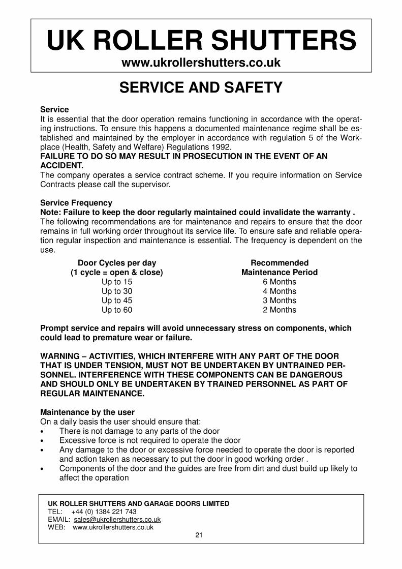
Service It is essential that the door operation remains functioning in accordance with the operat-ing instructions. To ensure this happens a documented maintenance regime shall be es-tablished and maintained by the employer in accordance with regulation 5 of the Work-place (Health, Safety and Welfare) Regulations 1992. FAILURE TO DO SO MAY RESULT IN PROSECUTION IN THE EVENT OF AN ACCIDENT. The company operates a service contract scheme. If you require information on Service Contracts please call the supervisor. Service Frequency Note: Failure to keep the door regularly maintained could invalidate the warranty . The following recommendations are for maintenance and repairs to ensure that the door remains in full working order throughout its service life. To ensure safe and reliable opera-tion regular inspection and maintenance is essential. The frequency is dependent on the use.
Door Cycles per day (1 cycle = open & close)
Up to 15 Up to 30 Up to 45 Up to 60
Recommended Maintenance Period
6 Months 4 Months 3 Months 2 Months
Prompt service and repairs will avoid unnecessary stress on components, which could lead to premature wear or failure. WARNING – ACTIVITIES, WHICH INTERFERE WITH ANY PART OF THE DOOR THAT IS UNDER TENSION, MUST NOT BE UNDERTAKEN BY UNTRAINED PER-SONNEL. INTERFERENCE WITH THESE COMPONENTS CAN BE DANGEROUS AND SHOULD ONLY BE UNDERTAKEN BY TRAINED PERSONNEL AS PART OF REGULAR MAINTENANCE. Maintenance by the user On a daily basis the user should ensure that: • There is not damage to any parts of the door • Excessive force is not required to operate the door • Any damage to the door or excessive force needed to operate the door is reported
and action taken as necessary to put the door in good working order . • Components of the door and the guides are free from dirt and dust build up likely to
affect the operation
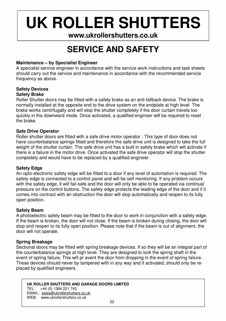
Maintenance – by Specialist Engineer A specialist service engineer in accordance with the service work instructions and task sheets should carry out the service and maintenance in accordance with the recommended service frequency as above. Safety Devices Safety Brake Roller Shutter doors may be fitted with a safety brake as an anti-fallback device. The brake is normally installed at the opposite end to the drive system on the endplate at high level. The brake works centrifugally and will stop the shutter completely if the door curtain travels too quickly in the downward mode. Once activated, a qualified engineer will be required to reset the brake. Safe Drive Operator Roller shutter doors are fitted with a safe drive motor operator . This type of door does not have counterbalance springs fitted and therefore the safe drive unit is designed to take the full weight of the shutter curtain. The safe drive unit has a built in safety brake which will activate if there is a failure in the motor drive. Once activated the safe drive operator will stop the shutter completely and would have to be replaced by a qualified engineer. Safety Edge An opto-electronic safety edge will be fitted to a door if any level of automation is required. The safety edge is connected to a control panel and will be self monitoring. If any problem occurs with the safety edge, it will fail-safe and the door will only be able to be operated via continual pressure on the control buttons. The safety edge protects the leading edge of the door and if it comes into contract with an obstruction the door will stop automatically and reopen to its fully open position. Safety Beam A photoelectric safety beam may be fitted to the door to work in conjunction with a safety edge. If the beam is broken, the door will not close. If the beam is broken during closing, the door will stop and reopen to its fully open position. Please note that if the beam is out of alignment, the door will not operate. Spring Breakage Sectional doors may be fitted with spring breakage devices. If so they will be an integral part of the counterbalance springs at high level. They are designed to lock the spring shaft in the event of spring failure. This will pr event the door from dropping in the event of spring failure. These devices should never by tampered with in any way and if activated, should only be re-placed by qualified engineers.
UK ROLLER SHUTTERS AND GARAGE DOORS LIMITED TEL: +44 (0) 1384 221 743 EMAIL: [email protected] WEB: www.ukrollershutters.co.uk
22
UK ROLLER SHUTTERS www.ukrollershutters.co.uk
SERVICE AND SAFETY
UK ROLLER SHUTTERS AND GARAGE DOORS LIMITED TEL: +44 (0) 1384 221 743 EMAIL: [email protected] WEB: www.ukrollershutters.co.uk
23
UK ROLLER SHUTTERS www.ukrollershutters.co.uk
SERVICE AND SAFETY
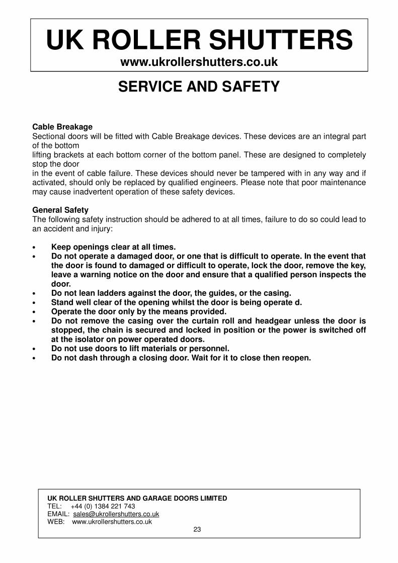
Cable Breakage Sectional doors will be fitted with Cable Breakage devices. These devices are an integral part of the bottom lifting brackets at each bottom corner of the bottom panel. These are designed to completely stop the door in the event of cable failure. These devices should never be tampered with in any way and if activated, should only be replaced by qualified engineers. Please note that poor maintenance may cause inadvertent operation of these safety devices. General Safety The following safety instruction should be adhered to at all times, failure to do so could lead to an accident and injury: • Keep openings clear at all times. • Do not operate a damaged door, or one that is difficult to operate. In the event that
the door is found to damaged or difficult to operate, lock the door, remove the key, leave a warning notice on the door and ensure that a qualified person inspects the door.
• Do not lean ladders against the door, the guides, or the casing. • Stand well clear of the opening whilst the door is being operate d. • Operate the door only by the means provided. • Do not remove the casing over the curtain roll and headgear unless the door is
stopped, the chain is secured and locked in position or the power is switched off at the isolator on power operated doors.
• Do not use doors to lift materials or personnel. • Do not dash through a closing door. Wait for it to close then reopen.
UK ROLLER SHUTTERS AND GARAGE DOORS LIMITED TEL: +44 (0) 1384 221 743 EMAIL: [email protected] WEB: www.ukrollershutters.co.uk
24
UK ROLLER SHUTTERS www.ukrollershutters.co.uk
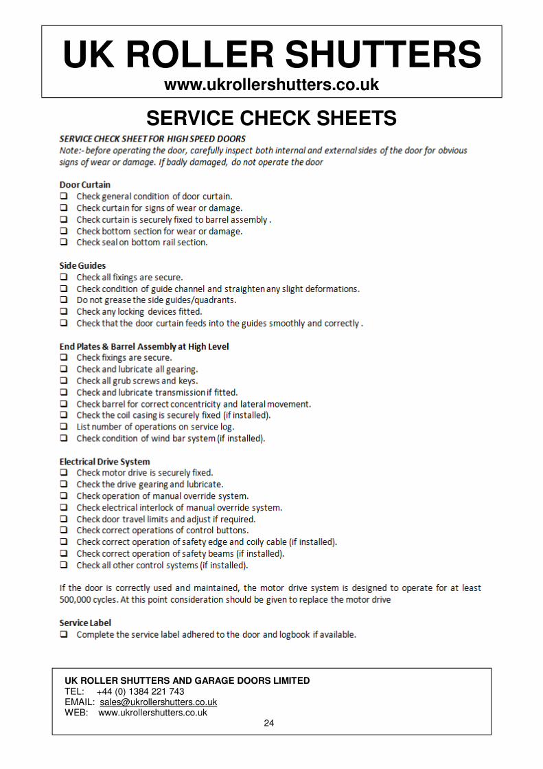
SERVICE CHECK SHEETS
UK ROLLER SHUTTERS www.ukrollershutters.co.uk
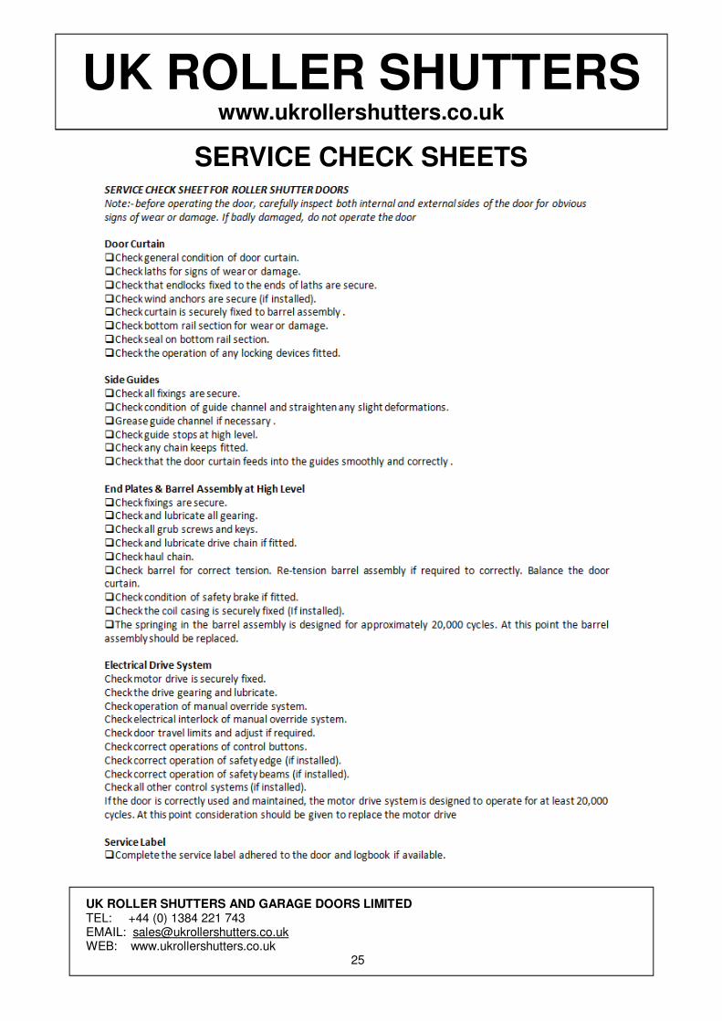
SERVICE CHECK SHEETS
UK ROLLER SHUTTERS AND GARAGE DOORS LIMITED TEL: +44 (0) 1384 221 743 EMAIL: [email protected] WEB: www.ukrollershutters.co.uk
25
UK ROLLER SHUTTERS www.ukrollershutters.co.uk
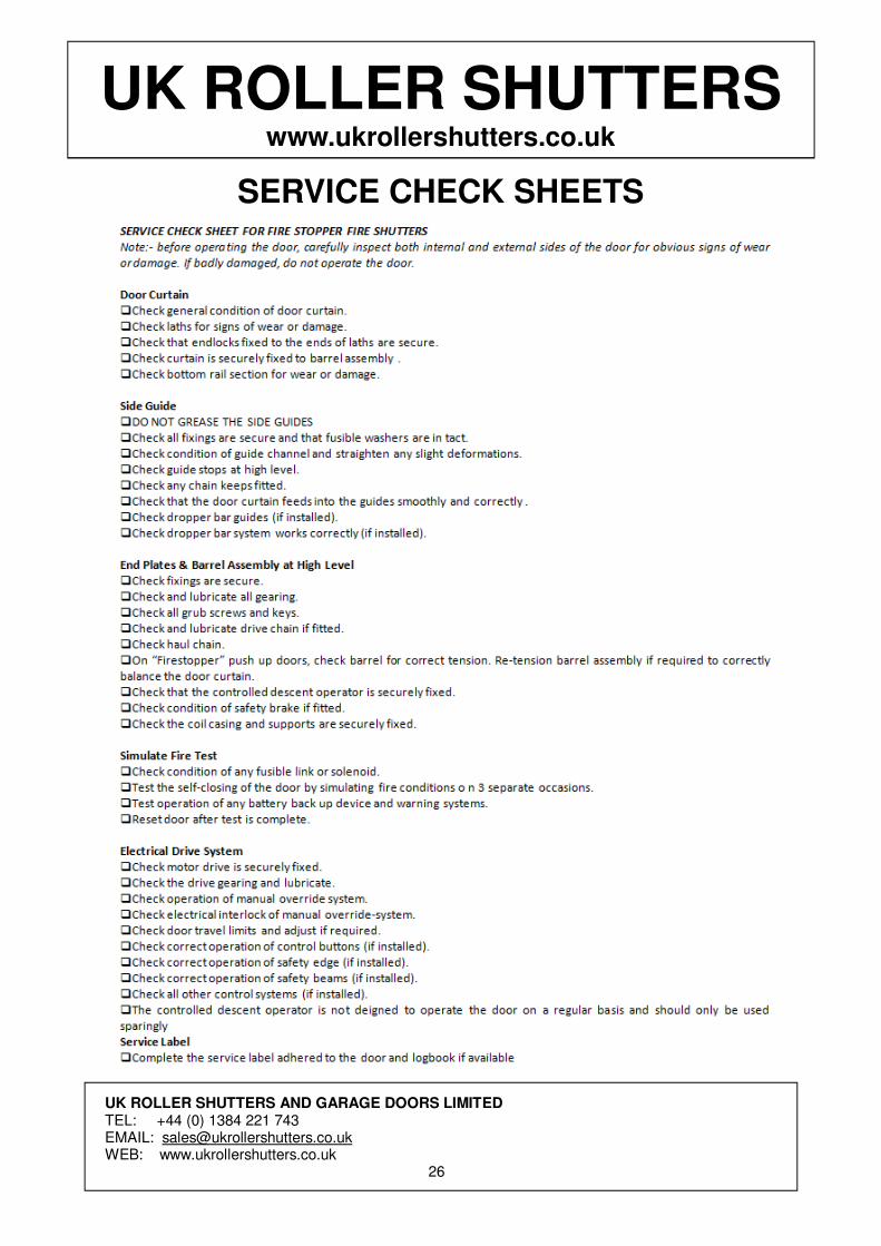
SERVICE CHECK SHEETS
UK ROLLER SHUTTERS AND GARAGE DOORS LIMITED TEL: +44 (0) 1384 221 743 EMAIL: [email protected] WEB: www.ukrollershutters.co.uk
26
UK ROLLER SHUTTERS www.ukrollershutters.co.uk
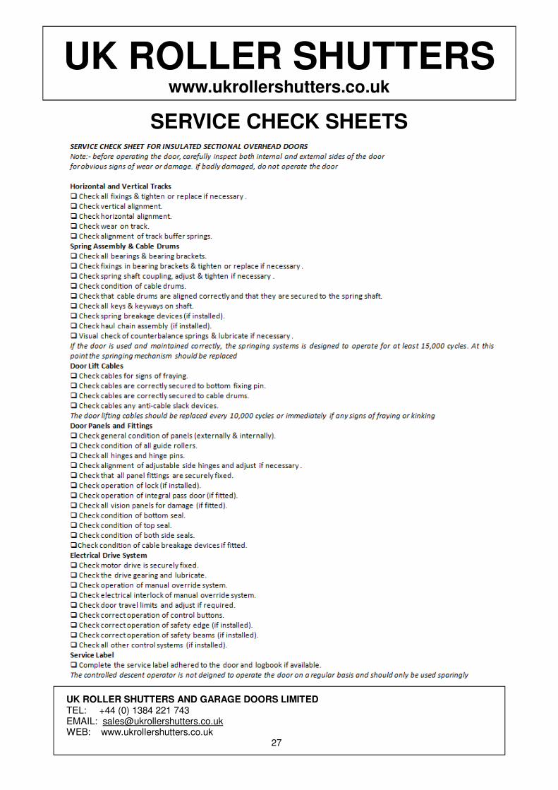
SERVICE CHECK SHEETS
UK ROLLER SHUTTERS AND GARAGE DOORS LIMITED TEL: +44 (0) 1384 221 743 EMAIL: [email protected] WEB: www.ukrollershutters.co.uk
27
UK ROLLER SHUTTERS www.ukrollershutters.co.uk
MAINTENANCE / REPAIR LOG
UK ROLLER SHUTTERS AND GARAGE DOORS LIMITED TEL: +44 (0) 1384 221 743 EMAIL: [email protected] WEB: www.ukrollershutters.co.uk
28
Date: Work Carried Out:
Engineers Name:
Date: Work Carried Out:
Engineers Name:
Date: Work Carried Out:
Engineers Name:
Date: Work Carried Out:
Engineers Name:
Date: Work Carried Out:
Engineers Name:
Date: Work Carried Out:
Engineers Name:
Date: Work Carried Out:
Engineers Name:
Date: Work Carried Out:
Engineers Name:
Date: Work Carried Out:
Engineers Name:
UK ROLLER SHUTTERS www.ukrollershutters.co.uk
NOTES
UK ROLLER SHUTTERS AND GARAGE DOORS LIMITED TEL: +44 (0) 1384 221 743 EMAIL: [email protected] WEB: www.ukrollershutters.co.uk
29
........................................................................................................................................
........................................................................................................................................
........................................................................................................................................
........................................................................................................................................
........................................................................................................................................
........................................................................................................................................
........................................................................................................................................
........................................................................................................................................
........................................................................................................................................
........................................................................................................................................
........................................................................................................................................
........................................................................................................................................
........................................................................................................................................
........................................................................................................................................
........................................................................................................................................
........................................................................................................................................
........................................................................................................................................
........................................................................................................................................
........................................................................................................................................
........................................................................................................................................
........................................................................................................................................
........................................................................................................................................
........................................................................................................................................
........................................................................................................................................
........................................................................................................................................
........................................................................................................................................
........................................................................................................................................
........................................................................................................................................
........................................................................................................................................
........................................................................................................................................
........................................................................................................................................
........................................................................................................................................
........................................................................................................................................
........................................................................................................................................
........................................................................................................................................

TEL: 0044(0) 1384 221743EMAIL: [email protected]