Embed Size (px)
Citation preview

UK Pile Design toBS EN 1997-1:2004 (EC7)and the UK National Annex
Chris Raison BEng MSc CEng MICE MASCE Raison Foster Associates
Presentation by:
1

Traditional Pile Design to BS 8004
Ultimate capacity based on calculation Factor of Safety varied between 2.0 and 3.0 for compression
loads and ≥ 3.0 for tension Actual FoS dependent on quality of GI, prior knowledge of
ground conditions and whether preliminary non-working load tests or contract proof load tests were carried out
Basic calculation methods have not changed2

Pile Design to EC7 So what is different?
EC7 method is a Limit State Design method: Ultimate Limit State (ULS)
States associated with collapse, structural failure, excessive deformation or loss of stability of the whole of the structure or any part of it
Serviceability Limit State (SLS) States that correspond to conditions beyond which specified
service requirements are no longer met
3

Pile Design to EC7 So what is different?
Separation of ULS and SLS condition Permanent and variable actions Favourable and unfavourable actions Use of characteristic ground properties Use of several partial factors Partial factors avoid failure but not necessarily movement
4

EC7 Limit States So what is different?
Adopts five distinct ultimate limit states: EQU – Loss of equilibrium (tilt or rotation) STR – Internal failure or excessive deformation
[Strength of structural material is significant]
GEO – Failure or excessive deformation of the ground[Strength of soil or rock is significant]
UPL – Uplift or buoyancy HYD – Hydraulic heave, erosion or piping
STR and GEO most important for pile design5

Pile Design to EC7 So what is different?
Basic inequality to be checked:
Ed is the design value of the effect of all the actions Rd is the design value of the corresponding resistance of the
ground or structure
For pile design, this inequality compares the design action Fd(usually load) against the design resistance Rd
6

Effect of Actions Ed Ed is the design value of the effect of all the actions:
Frep is the representative action (usually load) Xk is the characteristic value of the material property ad is the design value of a geometrical property γF and γm are relevant partial factors Design values:
7

UK National Annex UK has adopted Design Approach 1 - DA1 This requires two calculations:
A1 + R1 + M1 Combination 1 R4 + A2 + M1/M2 Combination 2
(Use M1 for calculating resistances) (Use M2 for unfavourable actions such as NSF)
For Combination 1, partial factors > 1.0 are applied to the actions only and does not usually control pile length
For Combination 2, partial factors > 1.0 are applied to resistances with smaller factors applied to variable actions
Both combinations should be checked
8

Design Actions Fd Fd is the design action
Frep is the representative action (usually load)
Gk is the characteristic permanent action Qk is the characteristic variable action Ak is the characteristic accidental action ψ is the factor for combination of variable actions
9

Partial Factors on Actions
ActionUK NA Factor Set EC7 Factor Set
A1 A2 A1 A2
PermanentUnfavourable 1.35 1.0 1.35 1.0
Favourable 1.0 1.0 1.0 1.0
VariableUnfavourable 1.5 1.3 1.5 1.3
Favourable 0 0 0 0
Notes:1. Factors can be applied to Actions or the Effect of Actions.2. Factors given above are for buildings which remain unchanged from EC7 values3. Combination factors for actions that can exist simultaneously are given in the
UK NA to BS EN 1990.4. There are a wider range of factors for bridges.
10

Ground Characterisation EC7 says a lot about determining characteristic or
representative soil properties Cautious estimate affecting the occurrence of the limit state Similar to BS 8002 and CIRIA 104 But most engineers already adopting cautious estimates Engineering judgement required Statistics can be applied, but is difficult because of the usual
limited number of samples and test data
For pile design, not a great deal of difference between soil parameters for EC7 design compared to BS 8004 design
11

Design Soil Parameters Design values are obtained by dividing the characteristic or
representative property by a partial factor
Usual properties to be factored are strength [but stiffness may need to be factored for horizontal load design]
Either effective stress strength, c’ and ϕ’, or undrained shear strength cu, or unconfined compressive strength UCS for rocks
For pile design to the UK National Annex, factored design soil parameters are not used except for negative shaft friction
12

Partial Factors on Soil Parameters
Soil PropertyUK NA Factor Set EC7 Factor Set
M1 M2 M1 M2
Friction Angle tan φ’ 1.0 1.25 1.0 1.25
Effective Cohesion c’ 1.0 1.25 1.0 1.25
Undrained Shear Strength Cu 1.0 1.4 1.0 1.4
Unconfined Strength UCS 1.0 1.4 1.0 1.4
Unit Weight γ 1.0 1.0
UK NA gives no factor for unit weight so presume 1.0; other factors remain unchanged.Not used directly for pile design, but may be used for Negative Shaft Friction.
13

Pile Design to EC7 Based on Resistances If not factored soil properties, what? For pile design, it is necessary to compare the design action
Fd (usually load) against the design resistance Rd
But note that this is now in terms of compression or tension load and compression or tension resistance:
As is usual, the design resistance Rc;d can be assumed to be the sum of the end bearing and shaft design resistances:
14

Pile Design to EC7 Based on Resistances The design resistances Rc;d or Rt;d are obtained from the
characteristic end bearing and shaft friction by using partial resistance factors
The characteristic end bearing and shaft friction can be computed using existing and recognisable methods either by calculation, static or dynamic load testing or correlation with CPT or other insitu ground testing
15

Pile Design by Calculation The characteristic base resistance and shaft resistance can be
calculated from the characteristic end bearing and shaft friction stresses as follows:
These are similar to the approach used for BS 8004 but include an additional model factor γRd to ‘correct’ the partial resistance factors (applied to the characteristic resistances to obtain the design resistance Rc;d)
At present, EC7 includes the above equations in clause 7.6.2.3 as an ‘alternative procedure’
16

Pile Shaft Friction Effective Stress Approach – Granular
Total Stress Approach – Cohesive or Rock (Weak Mudstone)
Beta Method – Soft Soils or Chalk
UCS Method – Sandstone, Limestone or Strong Mudstone
Basic calculation methods have not changed17

Pile End Bearing Effective Stress Approach – Granular
Total Stress Approach – Cohesive or Rock (Weak Mudstone)
SPT Method – Chalk
UCS Method – Sandstone, Limestone or Strong Mudstone
Basic calculation methods have not changed18

Partial Resistance Factors The design resistance Rd is obtained from the characteristic
end bearing and shaft friction by using partial resistance factors
The partial resistance factors in the UK National Annex have been modified to take account of the type of pile and whether the serviceability behaviour is to be determined either by load test or a rigorous and reliable calculation
The proposed model factor γRd used to ‘correct’ the partial resistance factors also depends on whether a ULS load test is proposed.
19

Partial Resistance Factors for Driven Piles
ComponentUK NA Factor Set EC7 Factor Set
R1 R4 (No SLS) R4 (SLS) R1 R2 R3 R4
Base 1.0 1.7 1.5 1.0 1.1 1.0 1.3
Shaft 1.0 1.5 1.3 1.0 1.1 1.0 1.3
Total 1.0 1.7 1.5 1.0 1.1 1.0 1.3
Tension 1.0 2.0 1.7 1.25 1.15 1.1 1.6
Main differences for resistance factors relate to:1. Factor set R4 where different values depend on whether SLS behaviour is verified or not
(test or calculation).2. Model factor to be applied to ground properties to derive characteristic values or
directly to the calculated shaft or end bearing capacities.3. Model factor 1.4, but can be reduced to 1.2 if a load test is completed to calculated
unfactored ultimate resistance (ULS check).
20

Partial Resistance Factors for Bored Piles
ComponentUK NA Factor Set EC7 Factor Set
R1 R4 (No SLS) R4 (SLS) R1 R2 R3 R4
Base 1.0 2.0 1.7 1.25 1.1 1.0 1.6
Shaft 1.0 1.6 1.4 1.0 1.1 1.0 1.3
Total 1.0 2.0 1.7 1.15 1.1 1.0 1.5
Tension 1.0 2.0 1.7 1.25 1.15 1.1 1.6
Main differences for resistance factors relate to:1. Factor set R4 where different values depend on whether SLS behaviour is verified or not
(test or calculation).2. Model factor to be applied to ground properties to derive characteristic values or
directly to the calculated shaft or end bearing capacities.3. Model factor 1.4, but can be reduced to 1.2 if a load test is completed to calculated
unfactored ultimate resistance (ULS check).
21

Partial Resistance Factors for Cfa Piles
ComponentUK NA Factor Set EC7 Factor Set
R1 R4 (No SLS) R4 (SLS) R1 R2 R3 R4
Base 1.0 2.0 1.7 1.1 1.1 1.0 1.45
Shaft 1.0 1.6 1.4 1.0 1.1 1.0 1.3
Total 1.0 2.0 1.7 1.1 1.1 1.0 1.4
Tension 1.0 2.0 1.7 1.25 1.15 1.1 1.6
Main differences for resistance factors relate to:1. Factor set R4 where different values depend on whether SLS behaviour is verified or not
(test or calculation).2. Model factor to be applied to ground properties to derive characteristic values or
directly to the calculated shaft or end bearing capacities.3. Model factor 1.4, but can be reduced to 1.2 if a load test is completed to calculated
unfactored ultimate resistance (ULS check).
22

Equivalent Lumped FoS
Pile TypeActions Resistance Factors Model
FactorLumped
FoSA2 R4 (No SLS) R4 (SLS)
DrivenEnd Bearing
1.1 1.7 1.51.4 2.6/2.3
1.2 2.2/2.0
DrivenEnd & Shaft
1.1 1.7/1.5 1.5/1.31.4 2.5/2.0
1.2 2.1/1.9
BoredShaft Friction
1.1 1.6 1.41.4 2.5/2.2
1.2 2.1/1.9
1. Partial factor on actions assumes 70% permanent and 30% variable.2. British Standard BS 8004 lumped FoS ranged from 2.0 to 3.0.3. Model factor 1.2 requires load test to be completed to calculated unfactored ultimate
resistance.4. Lower value for resistance factors dependent on SLS behaviour being verified (by load
test or reliable calculation).
23

Pile Design From Static Load Tests The design resistance Rc;d can also be obtained directly from
static load testing by applying correlation factors ξ and thesame partial resistance factors γ given above
The characteristic resistance is obtained from the static load test data using the following
Values for ξ1 and ξ2 depend on the number of static load tests with values decreasing as the number of load tests increases
24

Pile Design From Dynamic Impact Tests The characteristic resistance can also be obtained from
dynamic impact test data using the following similar relationship:
Values for ξ5 and ξ6 depend on the number of dynamic impact tests with values decreasing as the number of tests increases
An additional model factor γRd is also required: 0.85 when using signal matching (CAPWAP) 1.10 when the test includes pile head displacement 1.20 if no measurement of pile head displacement
25

Correlation Factors for Load TestingStatic Pile Load Tests (n = number of tested piles)
ξ for n = 1 2 3 4 ≥ 5
ξ1 1.55 1.47 1.42 1.38 1.35
ξ2 1.55 1.35 1.23 1.15 1.08
Dynamic Impact Tests (n = number of tested piles)
ξ for n = ≥ 2 ≥ 5 ≥ 10 ≥ 15 ≥ 20
ξ5 1.94 1.85 1.83 1.82 1.81
ξ6 1.90 1.76 1.70 1.67 1.66
26

Pile Design From Ground Test Results The characteristic resistance can also be obtained from
empirical relationships with ground test results (such as CPT) using the following similar relationship:
Values for ξ3 and ξ4 depend on the number of ground test results with values decreasing as the number of profiles increases
27

Correlation Factors for Ground TestsGround Test Results (n = number of profiles)
ξ for n = 1 2 3 4 5 7 10
ξ3 1.55 1.47 1.42 1.38 1.36 1.33 1.30
ξ4 1.55 1.39 1.33 1.29 1.26 1.20 1.15
EC7 requires that the method used to determine the pile characteristic resistance from ground test results should be established from pile load tests and comparable experience
These correlation factors were intended to be used with CPT profiles or pressuremeter data
However, EC7 includes the ‘alternative procedure’ or calculation method within section 7.6.2.3 covering ground test results
28

Design Example 600mm Cfa bored preliminary test pile Installed from a reduced level dig (3.5m below original level) Pile bored to 20.6m depth Founded in very weak Chalk Maximum test load 5,200kN at 61.3mm (Approx 10% D)
Example design based on: Calculation Static load test CPT profiles
29

Design Actions Fd for Design Example Example calculation
Factor Set A1
Factor Set A2
30

Design Parameters for Design Example
Geological Section31

Design Parameters for Design Example
Insitu SPT Data
Local Data
Old Data
Site Data
32

CPT Results 1
Insitu CPT Data
TerraceGravels
StructurelessChalk
MadeGround
33

CPT Results 2
StructurelessChalk
Very WeakChalk
34

CPT Results 3
TerraceGravels
StructurelessChalk
MadeGround
35

CPT Results 4
StructurelessChalk
Very WeakChalk
36

Design Parameters for Design Example
SoilDescription
Top LevelmOD
SoilProperties
DesignParameters
Granular BACKFILL 9.4 φ’ = 35° tan δ = 0.7 ks = 1.0
Very soft PEAT 8.4 cu = 25 α = 0.6
Dense gravelly SAND 7.4 φ’ = 35° tan δ = 0.7 ks = 1.0
Structureless CHALK 2.9 N = 5 bl/300mm qs = σv’ β β = 0.8
Weak Chalk -5.0 N = 15 bl/300mm qs = σv’ β β = 0.8 qb = 200 N
Enhanced base N = 40 bl/300mm qb = 8,000kPa
37

KPILE Bearing Capacity – β 0.45
cf 5,200kNmeasured
Calculation not representative
β too low
38

KPILE Bearing Capacity – β 0.80
cf 5,200kNmeasured
Calculation still on low side
39

KPILE Bearing Capacity – Enhanced Base
BC calculation down to here is the same as we
have always carried out
No changefor EC7
EC7 model and resistance
factors applied
Rc;d 2,968kN40
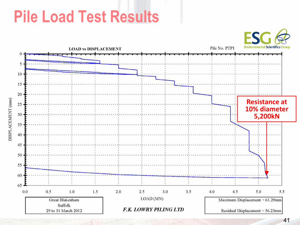
Pile Load Test Results
Resistance at 10% diameter
5,200kN
41

CEMSET Fit to Load Test ResultsMeasured Load-Settlement
Shaft Friction Qs
End Bearing Qb
Total Qult
Shaft Shortening
5,385kN
3,123kN
2,262kN
42

Design Based on Calculation Calculated design resistance Rc;d
Based on calculation with the best CEMSET fit to the measured load-settlement behaviour
43

Design Based on Static Load Tests Design resistance Rc;d
Note that this method is based on the measured resistance at 10% of the pile diameter rather than the extrapolated ultimate capacity (about 5,400kN based on CEMSET)
Assuming say 3 pile load tests and a stiff/strong structurewould allow a reduced correlation factor of 1.29 to be used giving Rc;d = 2,371kN
44

Design Based on CPT Profiles
45

Design Based on CPT ProfilesCPT 07Level Thickness qc qs/qc qs;k qb;k Rs;k Rb;k Rc;kmOD m MPa kPa kPa kN kN kN9.4 1.8 0.01 187.2 2.2 6.5 0.01 65 1721.9 5.3 6.5 0.01 65 6491.9 0.6 0.02 12
-11.2 13.1 4.5 0.02 90 1259-11.2 8.0 8000 2262
2081 2262 4343CPT 09Level Thickness qc qs/qc qs;k qb;k Rs;k Rb;k Rc;kmOD m MPa kPa kPa kN kN kN9.4 1.2 0.01 127.9 1.5 4.3 0.01 43 787.7 0.2 16.0 0.01 160 385.4 2.3 16.0 0.01 160 6944.7 0.7 1.0 0.02 20 119-0.6 5.3 1.0 0.02 20 200-8.6 8.0 4.0 0.02 80 754-8.6 6.0 0.02 120
-11.2 2.6 6.0 0.02 120 6000 588 16962470 1696 4167
46

Design Based on CPT Profiles Design resistance Rc;d
Assuming 10 number CPT profiles and a stiff/strong structure would allow a reduced correlation factor of 1.05 to be used giving Rc;d = 2,334kN
Note that this approach is not recommended for Chalk because of the unreliability of the empirical relationship between qc, qs;k and qb;k
47

Comparison Between Design Methods
Nominal pile load 2,000kN EC7 Design Action 2,180kN Design Resistance:
Based on Calculation 2,275kN to 2,968kN Based on Static Load Test 1,974kN to 2,371kN Based on CPT Profiles 1,703kN to 2,334kN
48

Conclusions
EC7 does not tell the Designer how to design but gives rules and procedures to be followed
EC7 has complicated design with the introduction of numerous partial factors; load factors, combination factors, material factors, resistance factors, model factors and correlation factors
But EC7 does provides a more logical framework
Thanks for Your Attention
49

50
And thanks to FK LowryPiling for their test data


![[Pascal Quignard] La Raison(BookFi.org)](https://img.pdfslide.us/doc/110x75/56d6bd291a28ab30168ce363/pascal-quignard-la-raisonbookfiorg.jpg)