Embed Size (px)
Citation preview

UK LIMITEDUK LIMITED
HANDOVER DOCUMENT
Door & HardwareFederation
raising standards
version2017
Engineering Excellence

Open, (ignor a second signal in opening), Close (when in pause), Open (when closing)
Open, Stop, Close, Stop, Open.
Open, Stop, Close, Open.
Hold button to open, hold a separate button to close. Not available with radio transmitters
1.1. Overview - Operating Guidance and Safety Information
Please read this operating manual before using your gate system for the first time and keep it safe for future use.
1.2. Safety:All SEA equipment has been CE marked showing that it complies with all health, safety, electrical and mechanical regulations at the time of manufacture. When the gates are installed to take advantage of these features they will comply with the machinery directive (EN13241-1, EN12453, EN12445, EN12604, EN12605, EN60204-1).
In order to help prevent accidents please take the following precautions:?Do not try to pass through the gate while it is moving?Wait until the gate is fully open before passing through ?Do not linger between the gates?Children must not play near the gates?Keep all remote control devices away from children ?Do not operate the gate by remote control unless it is in view?Do not attempt to impede the gates movement while it is in operation ?Report any signs of malfunction immediately to the automatic gate company responsible for
your gate system?Do not attempt to modify the gates or the automation system?Ensure your gate are regularly serviced
Your gates should be serviced every 6 - 12 months depending on the equipment used and the gates frequency of use.
1.3. Operating Logic: SEA motors are controlled by a PCB control panel. The control panel has a number of different Logics:
Automatic Logic:
Step By Step Logic:
Safety Logic:
Deadman Logic:
1.4. Safety Devices:SEA electric gates are compatible with every safety device on the market. Some common devices include:?Photocells, infra red safety beams ?Current sensing/ encoder's, obstacle detection built into the motor.?Safety edges, rubber strips which reduce impact force and revers gate at the same time?Loop detectors, detect metal moving near the gates, such as vehicles ?Light curtains, an array of 30-50 photocells forms a grid detecting everything that comes close. Every site is different and the gate machine fitted will to some degree be a bespoke piece of engineering. Do not interfere, tamper or remove and of the safety devices. Immediately report any potential malfunction to your gate engineer.
UK LIMITED
the engineers’ choice!the engineers’ choice!the engineers’ choice!Unit 2 Heron House, Ardath Road, Kings Norton, Birmingham, B38 9PJ
Birmingham Tel: 0121 433 3348Birmingham Fax: 0121 433 9650
London Tel: 020 8360 8022London Fax: 020 8364 2516
1 -4 Grange Mews, RO 28 The Grangeway, London, N21 2HG
1

Swing Gate Risk Assesment
3
6
2
8
8
9
7
6
2
8
1
4
2
2
3
5
4
5
2
Type of Gate Operator:
Underground System
Other Risks/Hazzards (mark on drawing)
The following form is only intended as a guide. It does not, nor is it intended to cover all and every risk associated with an automatic gate system. It is the installers responsibility to identify, assess and inform the client of any possible ricks of injury either real or perceived. This Risk Assessment Form, should be filled-in signed and a copy handed to the client
Type of InstallationPrivate Dwelling(House)...............
Private Multi-user (flats)................
Business/ Commercial..................
Installation LocationPrivate Area.................................
Private/Public Area......................
Unrestricted Public Area..............
Installation User ProfilePrivate instructucted users................
Private/Public instructucted users......
Un-instructucted Public users............
1. Gate, Leading edge:- Risk of trapping or crashing to be tested by dynamic impact metre.
2. Hinge Area:- Risk of crushing, trapping or shearing. Variable gaps between fixed and moving parts must be protected.
3. Gate Operators:- Variable gaps. The distance between gate leaf and operator must be 25mm or more.
4. Below Gate Frame:- Potential Foot Trap. Variable gaps under gate of more than 25mm must be protected.
5. Gate Design:- Risk of trapping, crushing or shearing. Alter or protect elements of the gate leaf due to their shape or position may cause a hazard
6. Space between gate and post/peir. Variable gap between fixed and moving parts. To be tested by dynamic impact metre.
7. Space between gate and wall/fixed object variable gap between fixed and moving parts to be tested by dynamic impact metre.
8. Ground Stops. Trip hazzard.
9. Gate travel area. Limit the possibility of impact by installing protection devices
Identified Risks List
Company Name:.......................................................................Address:........................................................................................................................................................................................................................................................................................Post Code:......................................Tel:.....................................Signed:............................................Date:.................................Print Name:...............................................................................
Client's Name:...............................................................Site Address: ..............................................................................................................................................................................................................................................Post Code:..................................Tel:.............................Signed:........................................Date:..........................Print Name:...................................................................
UK LIMITED
the engineers’ choice!the engineers’ choice!the engineers’ choice!Unit 2 Heron House, Ardath Road, Kings Norton, Birmingham, B38 9PJ
Birmingham Tel: 0121 433 3348Birmingham Fax: 0121 433 9650
London Tel: 020 8360 8022London Fax: 020 8364 2516
1 -4 Grange Mews, RO 28 The Grangeway, London, N21 2HG
2
3 4
2
5
6
7
8
9
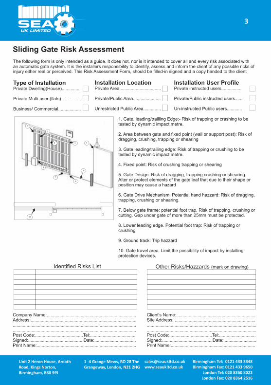
The following form is only intended as a guide. It does not, nor is it intended to cover all and every risk associated with an automatic gate system. It is the installers responsibility to identify, assess and inform the client of any possible ricks of injury either real or perceived. This Risk Assessment Form, should be filled-in signed and a copy handed to the client
Type of InstallationPrivate Dwelling(House)...............
Private Multi-user (flats)................
Business/ Commercial..................
Installation LocationPrivate Area.................................
Private/Public Area......................
Unrestricted Public Area..............
Installation User ProfilePrivate instructed users................
Private/Public instructed users......
Un-instructed Public users............
1. Gate, leading/trailling Edge:- Risk of trapping or crashing to be tested by dynamic impact metre.
2. Area between gate and fixed point (wall or support post): Risk of dragging, crushing, trapping or shearing
3. Gate leading/trailing edge: Risk of trapping or crushing to be tested by dynamic impact metre.
4. Fixed point: Risk of crushing trapping or shearing
5. Gate Design: Risk of dragging, trapping crushing or shearing. Alter or protect elements of the gate leaf that due to their shape or position may cause a hazard
6. Gate Drive Mechanism: Potential hand hazzard: Risk of dragging, trapping, crushing or shearing.
7. Below gate frame: potential foot trap. Risk of trapping, crushing or cutting. Gap under gate of more than 25mm must be protected.
8. Lower leading edge. Potential foot trap: Risk of trapping or crushing
9. Ground track: Trip hazzard
10. Gate travel area. Limit the possibility of impact by installing protection devices.
Other Risks/Hazzards (mark on drawing)Identified Risks List
1
10
Sliding Gate Risk Assessment
UK LIMITED
the engineers’ choice!the engineers’ choice!the engineers’ choice!Unit 2 Heron House, Ardath Road, Kings Norton, Birmingham, B38 9PJ
Birmingham Tel: 0121 433 3348Birmingham Fax: 0121 433 9650
London Tel: 020 8360 8022London Fax: 020 8364 2516
1 -4 Grange Mews, RO 28 The Grangeway, London, N21 2HG
3
Company Name:.......................................................................Address:........................................................................................................................................................................................................................................................................................Post Code:......................................Tel:.....................................Signed:............................................Date:.................................Print Name:...............................................................................
Client's Name:...............................................................Site Address: ..............................................................................................................................................................................................................................................Post Code:..................................Tel:.............................Signed:........................................Date:..........................Print Name:...................................................................

Traffic Barrier Risk Assesment
The following form is only intended as a guide. It does not, nor is it intended to cover all and every risk associated with an automatic gate system. It is the installers responsibility to identify, assess and inform the client of any possible ricks of injury either real or perceived. This Risk Assessment Form, should be filled-in signed and a copy handed to the client
Type of InstallationPrivate Dwelling(House)...............
Private Multi-user (flats)................
Business/ Commercial..................
Installation LocationPrivate Area.................................
Private/Public Area......................
Unrestricted Public Area..............
Installation User ProfilePrivate instructed users................
Private/Public instructed users......
Un-instructucted Public users............
1. Gate, leading lower edge:- Risk of impact to be tested by dynamic impact metre.
2. Gate, leading upper edge:- Risk of impact to be tested by dynamic impact metre.
3. Gate leading/trailing edge: Risk of trapping or crushing to be tested by dynamic impact metre.
4. Fixed point: Risk of crushing trapping or shearing
5. Gate Design: Risk of dragging, trapping crushing or shearing. Alter or protect elements of the gate leaf that due to their shape or position may cause a hazard
6. Gate Drive Mechanism: Potential hand hazzard: Risk of dragging, trapping, crushing or shearing.
7. Below gate frame: potential foot trap. Risk of trapping, crushing or cutting. Gap under gate of more than 25mm must be protected.
8. Lower leading edge. Potential foot trap: Risk of trapping or crushing
9. Ground track: Trip hazzard
10. Gate travel area. Limit the possibility of impact by installing protection devices.
Other Risks/Hazzards (mark on drawing)Identified Risks List
1
43
2
UK LIMITED
the engineers’ choice!the engineers’ choice!the engineers’ choice!Unit 2 Heron House, Ardath Road, Kings Norton, Birmingham, B38 9PJ
Birmingham Tel: 0121 433 3348Birmingham Fax: 0121 433 9650
London Tel: 020 8360 8022London Fax: 020 8364 2516
1 -4 Grange Mews, RO 28 The Grangeway, London, N21 2HG
4
Company Name:.......................................................................Address:........................................................................................................................................................................................................................................................................................Post Code:......................................Tel:.....................................Signed:............................................Date:.................................Print Name:...............................................................................
Client's Name:...............................................................Site Address: ..............................................................................................................................................................................................................................................Post Code:..................................Tel:.............................Signed:........................................Date:..........................Print Name:...................................................................

Manual Releases
Half Tank
Full Tank/ Super Full Tank
Compact / Field Leaver
Compact / Field Key
Lepus
Saturn
Sprint
Alpha
Surf
Ger
Vela Industrial
Bull BollardLepus Box
Big 4000
Storm
Insert & turn key
Lift flap & turn key
Rotate away from gate post
Insert key, turn and pull open leaver
Remove cover & turn knob on motor base
Insert key and open box cover
Pull red handle
Insert key and screw anticlock wise to relase
Insert key and turn anticlock wise to reales
Insert key and turn
Rotate arm to reales
Insert key and turn
pull leaver open
Insert key, rotate & pull leaver
Insert key and turn
Insert key and turn
Lift flap, insert key, turn key
Open case insert key & turn.
Lift flap, insert key, turn key
Open case insert key & turn.
Mini Tank
UK LIMITED
the engineers’ choice!the engineers’ choice!the engineers’ choice!Unit 2 Heron House, Ardath Road, Kings Norton, Birmingham, B38 9PJ
Birmingham Tel: 0121 433 3348Birmingham Fax: 0121 433 9650
London Tel: 020 8360 8022London Fax: 020 8364 2516
1 -4 Grange Mews, RO 28 The Grangeway, London, N21 2HG
Tick if used
Tick if used
Tick if used
Tick if used
Tick if used
Tick if used
Tick if used
Tick if used
Tick if used
Tick if used
Tick if used
Tick if used
Tick if used
Tick if used
Tick if used
Tick if used
5
Installer Company NameInstaller Company AddressInstaller Date
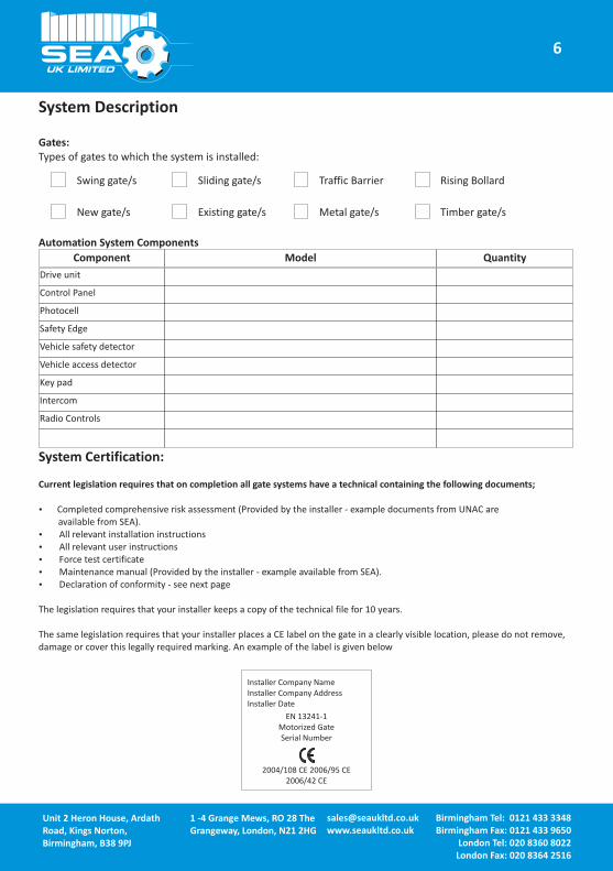
System Description
Gates:Types of gates to which the system is installed:
Automation System Components
Swing gate/s Sliding gate/s Traffic Barrier Rising Bollard
New gate/s Existing gate/s Metal gate/s Timber gate/s
Component Model Quantity
Drive unit
Control Panel
Photocell
Safety Edge
Vehicle safety detector
Vehicle access detector
Key pad
Intercom
Radio Controls
System Certification:
Current legislation requires that on completion all gate systems have a technical containing the following documents;
?Completed comprehensive risk assessment (Provided by the installer - example documents from UNAC are available from SEA).
?All relevant installation instructions ?All relevant user instructions?Force test certificate?Maintenance manual (Provided by the installer - example available from SEA). ?Declaration of conformity - see next page
The legislation requires that your installer keeps a copy of the technical file for 10 years.
The same legislation requires that your installer places a CE label on the gate in a clearly visible location, please do not remove, damage or cover this legally required marking. An example of the label is given below
EN 13241-1Motorized GateSerial Number
2004/108 CE 2006/95 CE 2006/42 CE
UK LIMITED
the engineers’ choice!the engineers’ choice!the engineers’ choice!Unit 2 Heron House, Ardath Road, Kings Norton, Birmingham, B38 9PJ
Birmingham Tel: 0121 433 3348Birmingham Fax: 0121 433 9650
London Tel: 020 8360 8022London Fax: 020 8364 2516
1 -4 Grange Mews, RO 28 The Grangeway, London, N21 2HG
6
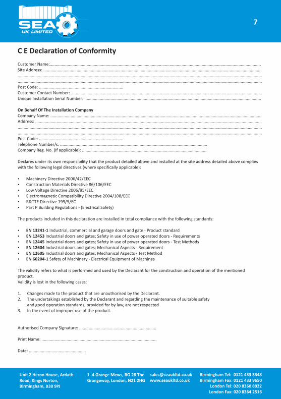
C E Declaration of Conformity
Customer Name:..................................................................................................................................................................................Site Address: ....................................................................................................................................................................................................................................................................................................................................................................................................................................................................................................................................................................................................................Post Code: .......................................................................Customer Contact Number: .................................................................................................................................................................Unique Installation Serial Number: .....................................................................................................................................................
On Behalf Of The Installation CompanyCompany Name: ..................................................................................................................................................................................Address: ...........................................................................................................................................................................................................................................................................................................................................................................................................................................................................................................................................................................................................................Post Code: .......................................................................Telephone Number/s: ............................................................................................................................Company Reg. No. (If applicable): .........................................................................................................
Declares under its own responsibility that the product detailed above and installed at the site address detailed above complies with the following legal directives (where specifically applicable):
?Machinery Directive 2006/42/EEC?Construction Materials Directive 86/106/EEC?Low Voltage Directive 2006/95/EEC?Electromagnetic Compatibility Directive 2004/108/EEC?R&TTE Directive 199/5/EC?Part P Building Regulations - (Electrical Safety)
The products included in this declaration are installed in total compliance with the following standards:
?EN 13241-1 Industrial, commercial and garage doors and gate - Product standard?EN 12453 Industrial doors and gates; Safety in use of power operated doors - Requirements?EN 12445 Industrial doors and gates; Safety in use of power operated doors - Test Methods?EN 12604 Industrial doors and gates; Mechanical Aspects - Requirement?EN 12605 Industrial doors and gates; Mechanical Aspects - Test Method?EN 60204-1 Safety of Machinery - Electrical Equipment of Machines
The validity refers to what is performed and used by the Declarant for the construction and operation of the mentioned product. Validity is lost in the following cases:
1. Changes made to the product that are unauthorised by the Declarant.2. The undertakings established by the Declarant and regarding the maintenance of suitable safety
and good operation standards, provided for by law, are not respected 3. In the event of improper use of the product.
Authorised Company Signature: .................................................................
Print Name: .................................................................................................
Date: ................................................
UK LIMITED
the engineers’ choice!the engineers’ choice!the engineers’ choice!Unit 2 Heron House, Ardath Road, Kings Norton, Birmingham, B38 9PJ
Birmingham Tel: 0121 433 3348Birmingham Fax: 0121 433 9650
London Tel: 020 8360 8022London Fax: 020 8364 2516
1 -4 Grange Mews, RO 28 The Grangeway, London, N21 2HG
7

1.1. Site Summary and Check List
Preliminary Checks Risk Assessments Completed Gates suitable for automationGates move smoothly with no stiff pointsLeaf weight & length within operator spec
Installation Checks Components installed in accordance with manufacturers instructions Actuation points/ controls outside hazard areaCE Mark fixed to gate Suitable warning labels applied Power supply connected to isolator
Functional Checks Operating devicesStop devices PhotocellsOther safety devices Control panel settingsManual release operation Connection to fire alarm system (if applicable)
Method of Safe Operation (select one)Dead-man hold to run controls usedImpact forces tested in accordance with BS EN12453 & BS EN12445
Training DocumentationCustomer has been informed of safe operation & residual risksEC Declaration of Conformity provided Maintenance requirements providedManual release key & instructions provided
Engineers Signature: Date:
Print Name:
Customers Signature: Date:
Print Name:
UK LIMITED
the engineers’ choice!the engineers’ choice!the engineers’ choice!Unit 2 Heron House, Ardath Road, Kings Norton, Birmingham, B38 9PJ
Birmingham Tel: 0121 433 3348Birmingham Fax: 0121 433 9650
London Tel: 020 8360 8022London Fax: 020 8364 2516
1 -4 Grange Mews, RO 28 The Grangeway, London, N21 2HG
8

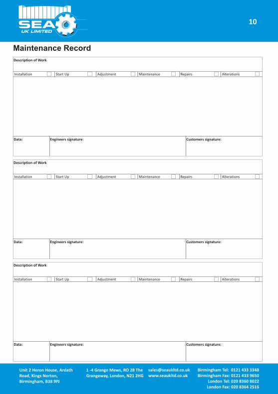
Maintenance Record
Installation Start Up Adjustment Maintenance Repairs Alterations
Description of Work
Data: Engineers signature: Customers signature:
UK LIMITED
the engineers’ choice!the engineers’ choice!the engineers’ choice!Unit 2 Heron House, Ardath Road, Kings Norton, Birmingham, B38 9PJ
Birmingham Tel: 0121 433 3348Birmingham Fax: 0121 433 9650
London Tel: 020 8360 8022London Fax: 020 8364 2516
1 -4 Grange Mews, RO 28 The Grangeway, London, N21 2HG
Installation Start Up Adjustment Maintenance Repairs Alterations
Description of Work
Data: Engineers signature: Customers signature:
Installation Start Up Adjustment Maintenance Repairs Alterations
Description of Work
Data: Engineers signature: Customers signature:
9
Maintenance Record
Installation Start Up Adjustment Maintenance Repairs Alterations
Description of Work
Data: Engineers signature: Customers signature:
UK LIMITED
the engineers’ choice!the engineers’ choice!the engineers’ choice!Unit 2 Heron House, Ardath Road, Kings Norton, Birmingham, B38 9PJ
Birmingham Tel: 0121 433 3348Birmingham Fax: 0121 433 9650
London Tel: 020 8360 8022London Fax: 020 8364 2516
1 -4 Grange Mews, RO 28 The Grangeway, London, N21 2HG
Installation Start Up Adjustment Maintenance Repairs Alterations
Description of Work
Data: Engineers signature: Customers signature:
Installation Start Up Adjustment Maintenance Repairs Alterations
Description of Work
Data: Engineers signature: Customers signature:
10

Door & HardwareFederation
raising standards
Engineering Excellence
SEA (UK) Limited: Birmingham
Unit 2 Ardath Road
Kings Norton,
Birmingham
West Midlands
B38 9PJ
Tel: 0845 233 8000, Fax: 0121 433 5695,
Email: [email protected]
SEA (UK) Limited: London
Tel: 020 8360 8022, Fax: 020 8364 2516,
Email: [email protected]
http://www.seaukltd.co.uk
London Trade Counter
1-4 Grange Mews
Rear of 28 The Grangeway
London
N21 2HG.