Embed Size (px)
Citation preview
UIR Series Universal Isolation Relay
Installation & Operation Manual
TRANSDATA, INC. 2560 TARPLEY ROAD • CARROLLTON, TEXAS 75006 • TEL (972) 418-7717 • FAX (972) 418-7774 Website: www.transdatainc.com E-mail: [email protected]
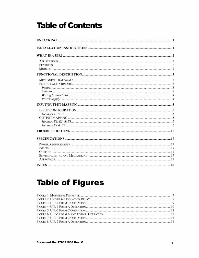
Table of Contents
UNPACKING ............................................................................................................................................1
INSTALLATION INSTRUCTIONS .......................................................................................................1
WHAT IS A UIR? .....................................................................................................................................2
APPLICATIONS...........................................................................................................................................2 FEATURES .................................................................................................................................................2 MODELS ....................................................................................................................................................2
FUNCTIONAL DESCRIPTION..............................................................................................................3
MECHANICAL HARDWARE ........................................................................................................................3 ELECTRICAL HARDWARE ..........................................................................................................................3
Inputs.....................................................................................................................................................3 Outputs ..................................................................................................................................................3 Wiring Connections...............................................................................................................................4 Power Supply ........................................................................................................................................4
INPUT/OUTPUT MAPPING...................................................................................................................5
INPUT CONFIGURATION.....................................................................................................................5 Headers J1 & J2....................................................................................................................................5
OUTPUT MAPPING ...............................................................................................................................5 Headers E1, E2, & E3...........................................................................................................................5 Headers E4 & E5 ..................................................................................................................................6
TROUBLESHOOTING..........................................................................................................................15
SPECIFICATIONS .................................................................................................................................17
POWER REQUIREMENTS ..........................................................................................................................17 INPUTS ....................................................................................................................................................17 OUTPUTS.................................................................................................................................................17 ENVIRONMENTAL AND MECHANICAL .....................................................................................................17 APPROVALS.............................................................................................................................................17
INDEX ......................................................................................................................................................18
Table of Figures
FIGURE 1: MOUNTING TEMPLATE ................................................................................................................7 FIGURE 2: UNIVERSAL ISOLATION RELAY....................................................................................................8 FIGURE 3: UIR-1 FORM C OPERATION .........................................................................................................9 FIGURE 4: UIR-1 FORM A OPERATION.......................................................................................................10 FIGURE 5: UIR-5 FORM C OPERATION .......................................................................................................11 FIGURE 6: UIR-5 FORM A AND FORM C OPERATION..................................................................................12 FIGURE 7: UIR-3 FORM C OPERATION .......................................................................................................13 FIGURE 8: UIR-3 FORM A OPERATION.......................................................................................................14
Document No. 170071000 Rev. C i
Installation
1 UNPACKING The shipping carton should contain the following:
• UIR - Universal Isolation Relay Be sure to inspect the UIR for any shipping damages. If damage is evident, notify the carrier accordingly, and contact TransData.
INSTALLATION INSTRUCTIONS
1. Select a suitable mounting location for the UIR. To install a UIR, follow these steps:
2. Using as a reference, drill 3/16” holes. Figure 1: Mounting Template
3. Mount the UIR in the upright vertical position using 4 appropriate #8 screws. Secure the screws tightly.
4. Select appropriate 5x20mm fuse ratings, depending on types of loads. Install output fuses at F1, F2, and F3, depending on UIR model. Reference . Figure 2: Universal Isolation Relay
5. Disable AC power source. If 120VAC power supply is used, connect the AC power source to the UIR using 16 gauge stranded wire with an insulation rating of at least 300 volts. If 240VAC or 277VAC power supply is used, then the wire insulation rating should be at least 600 volts.
6. If the UIR is not mounted to a grounded surface, then TransData recommends connecting 16 AWG or larger wire between one of the mounting plate screws and a suitable earth ground to insure proper operation of the UIR device.
IMPORTANT!
The UIR must be mounted in the upright vertical position for proper operation.
Document No. 170071000 Rev. C 1
Introduction
2 WHAT IS A UIR? The Universal Isolation Relay provides a pulse distribution point to various devices in remote locations. The Relay is designed to isolate and protect network components for safety and security. Reference Fi
. gure 2: Universal
Isolation Relay
Applications The UIR can be utilized in the following applications:
• Isolation for substation pulse inputs/outputs
• Meter pulse isolation and pulse replication
• DC pilot wire signaling for long distances
• Pulse bounce filtering
Features The UIR provides the following features:
• Two Form A or Form C inputs accepting contact closures, open collector inputs, or AC or DC voltage signals
• Power supply accepting 120 - 277 VAC without hardware configuration changes
• Input/Output mapping allowing inputs to be routed to any combination of the three outputs using field configurable PCB header shunts
• 1 Amp Fast Acting 5x20mm fuse input overcurrent protection
• Input and Output LED indicators
• Fused outputs
• Maximum 10 pulse per second throughput
• Pulse debouncing in Form A or Form C mode
• Bistable or Monostable configurable operation, depending on model
• Two or three Form C mercury wetted relay outputs, depending on model
Models The UIR is available in three models:
MODEL CONFIGURATION UIR-1 2 Inputs/2 Outputs, Bistable operation UIR-5 2 Inputs/3 Outputs, Bistable operation UIR-3 2 Inputs/3 Outputs, Bistable & Monostable operation
Document No. 170071000 Rev. C 2
Hardware
3 FUNCTIONAL DESCRIPTION
Mechanical Hardware The printed circuit board is fastened to an aluminum plate by means of four standoffs and #4 screws. The electronics are protected by a standard dust cover. As an option, a sealable dust cover or a NEMA 3R security enclosure can be provided.
Electrical Hardware
Inputs The UIR provides two input connections, which can be wired to any pulse source, such as an electric meter pulse initiator output. These inputs provide the following features for the UIR:
• Form A (two-wire) or Form C (three-wire) operation, which are independently field configurable for both inputs using PCB header shunts. J1 header configures Form A or Form C operation for input 1, while J2 header configures Form A or Form C operation for input 2. Reference . Figure 2: Universal Isolation Relay
• Input to output pulse stream mapping - each of the two inputs can be mapped to any one, two, or all three of the pulse relay outputs. The two inputs, however, should not be mapped to the same output. See INPUT/OUTPUT MAPPING, page 5.
• The UIR-3 provides selection of bistable or monostable (momentary) input to output operation. With bistable operation, the output always corresponds to the last mapped input state. With monostable operation, however, the output always returns to starting state after approximately 0.25 seconds.
• An input wetting voltage of 5.5 to 8.5 VDC open circuit with a short circuit current capability of less than 5 mA.
• Input pulse rates up to 10 pulses per second are permissible during bistable operation.
• The inputs are designed to accept dry relay contacts or open collector pulse sources. If required, however, 60 VDC bipolar pilot wire operation can be implemented, as well as the use of 120 VAC signals applied to the inputs.
Outputs Depending on the model, the UIR provides two or three, fuse protected, dry Form C mercury wetted relay outputs. As an option, the UIR can be shipped with user specified output fuses. If output fuses are not installed prior to shipment, install fuses in the fuse clips labeled F1, F2, and F3 for the corresponding output on the PC board. The recommended ratings are 1/2 - 2 A fast acting 5x20mm fuses.
Document No. 170071000 Rev. C 3
Wiring Connections User terminations are facilitated using 300V, wire clamp, terminal strips that will accommodate 18 to 12 AWG wire. The UIR is designed to operate with input wire lengths of up to 2500 feet when using twisted pair, or shielded twisted pair 18 to 12 AWG copper wire, or with a maximum input wire impedance of 1.5kΩ if other wire type is used. Terminal block designations for the input and output connections as well as AC power are labeled on the printed circuit board silkscreen as shown in Fi . gure 2: Universal Isolation Relay
Meter Input Wiring
If Form A inputs are used, CH1 “Y” is input one and CH2 “Y” is input two. The “K” INPUT terminal is the common terminal for both inputs, regardless of the form.
If Form C inputs are used, CH1 “Y” and CH1 “Z” are input one and CH2 “Y” and CH2 “Z” are input two.
Output Wiring
Each output provides a “K”, “Y”, and “Z” terminal. Form C operation requires a “K”, “Y”, and “Z” connection for each output. Form A output connections are all achieved by using only the “K” and “Y” or “K” and “Z” terminals.
Power Supply The AC input to the power supply accommodates 120 - 277 VAC at a maximum of 1.7 VA of burden. There are no hardware configuration changes to operate at different voltages. A 1 Amp fast acting 5x20mm line fuse (F4), with protective cover, provides input overcurrent protection.
Document No. 170071000 Rev. C 4
I/O MAPPING
4 INPUT/OUTPUT MAPPING Reference
figures 3-8.
INPUT CONFIGURATION
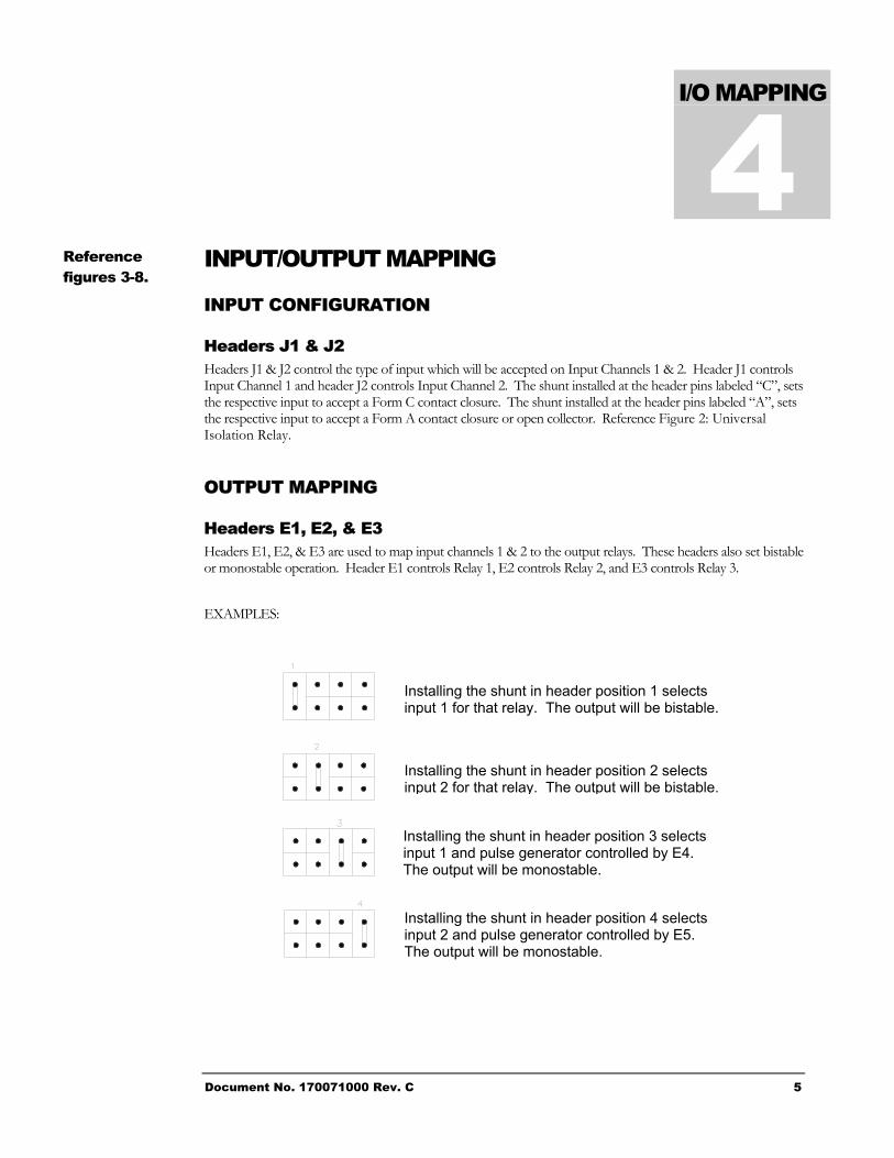
Headers J1 & J2 Headers J1 & J2 control the type of input which will be accepted on Input Channels 1 & 2. Header J1 controls Input Channel 1 and header J2 controls Input Channel 2. The shunt installed at the header pins labeled “C”, sets the respective input to accept a Form C contact closure. The shunt installed at the header pins labeled “A”, sets the respective input to accept a Form A contact closure or open collector. Reference Figure 2: Universal Isolation Relay.
OUTPUT MAPPING
Headers E1, E2, & E3 Headers E1, E2, & E3 are used to map input channels 1 & 2 to the output relays. These headers also set bistable or monostable operation. Header E1 controls Relay 1, E2 controls Relay 2, and E3 controls Relay 3.
EXAMPLES:
Installing the shunt in header position 1 selects input 1 for that relay. The output will be bistable.
Installing the shunt in header position 2 selects input 2 for that relay. The output will be bistable.
Installing the shunt in header position 3 selects input 1 and pulse generator controlled by E4. The output will be monostable.
Installing the shunt in header position 4 selects input 2 and pulse generator controlled by E5. The output will be monostable.
Document No. 170071000 Rev. C 5
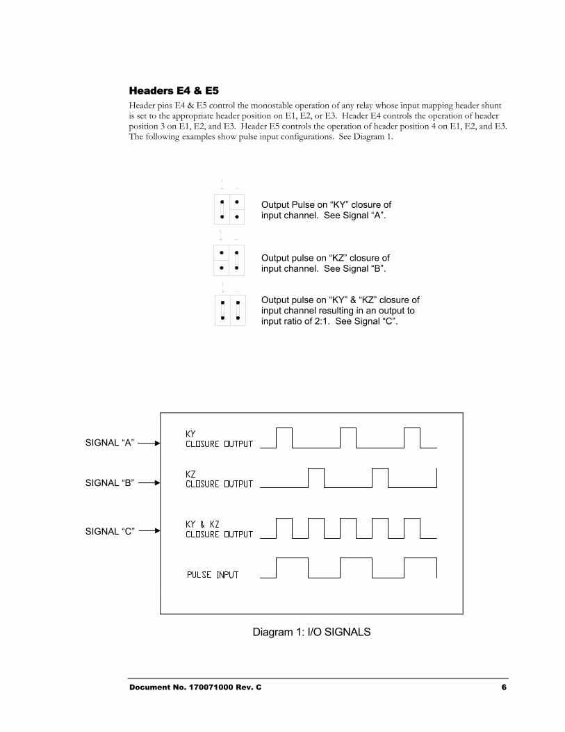
Headers E4 & E5 Header pins E4 & E5 control the monostable operation of any relay whose input mapping header shunt is set to the appropriate header position on E1, E2, or E3. Header E4 controls the operation of header position 3 on E1, E2, and E3. Header E5 controls the operation of header position 4 on E1, E2, and E3. The following examples show pulse input configurations. See Diagram 1.
Output Pulse on “KY” closure of input channel. See Signal “A”.
Output pulse on “KZ” closure of input channel. See Signal “B”.
Output pulse on “KY” & “KZ” closure of input channel resulting in an output to input ratio of 2:1. See Signal “C”.
Diagram 1: I/O SIGNALS
SIGNAL “A”
SIGNAL “B”
SIGNAL “C”
Document No. 170071000 Rev. C 6
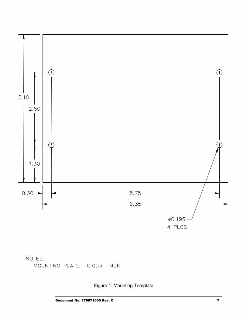
Figure 1: Mounting Template
Document No. 170071000 Rev. C 7
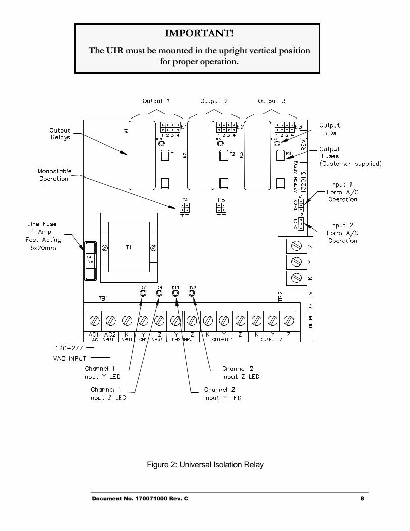
Figure 2: Universal Isolation Relay
IMPORTANT!
The UIR must be mounted in the upright vertical position for proper operation.
Document No. 170071000 Rev. C 8
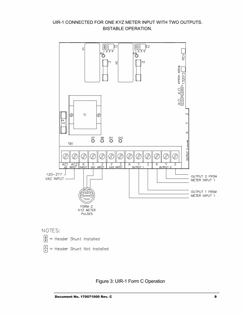
UIR-1 CONNECTED FOR ONE KYZ METER INPUT WITH TWO OUTPUTS. BISTABLE OPERATION.
Figure 3: UIR-1 Form C Operation
Document No. 170071000 Rev. C 9
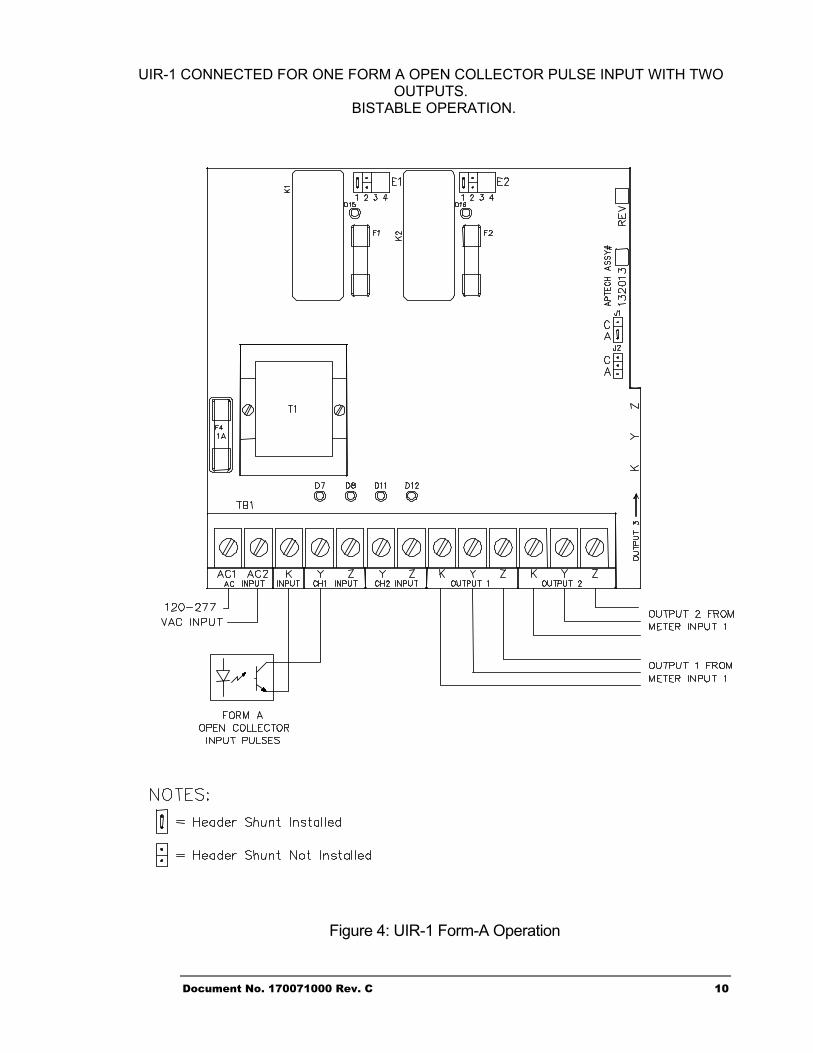
UIR-1 CONNECTED FOR ONE FORM A OPEN COLLECTOR PULSE INPUT WITH TWO OUTPUTS.
BISTABLE OPERATION.
Figure 4: UIR-1 Form-A Operation
Document No. 170071000 Rev. C 10
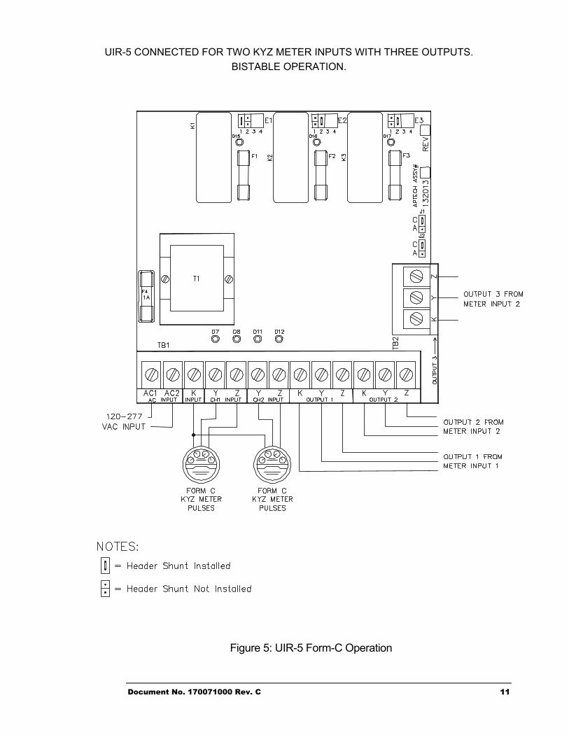
UIR-5 CONNECTED FOR TWO KYZ METER INPUTS WITH THREE OUTPUTS. BISTABLE OPERATION.
Figure 5: UIR-5 Form-C Operation
Document No. 170071000 Rev. C 11
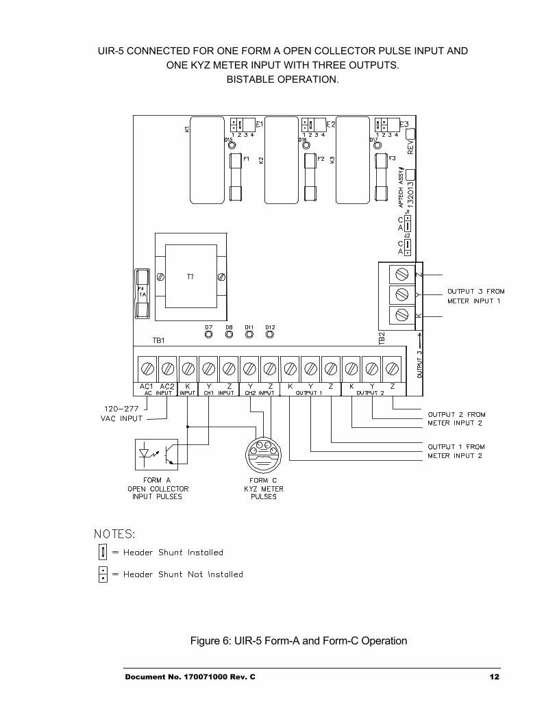
UIR-5 CONNECTED FOR ONE FORM A OPEN COLLECTOR PULSE INPUT AND ONE KYZ METER INPUT WITH THREE OUTPUTS.
BISTABLE OPERATION.
Figure 6: UIR-5 Form-A and Form-C Operation
Document No. 170071000 Rev. C 12
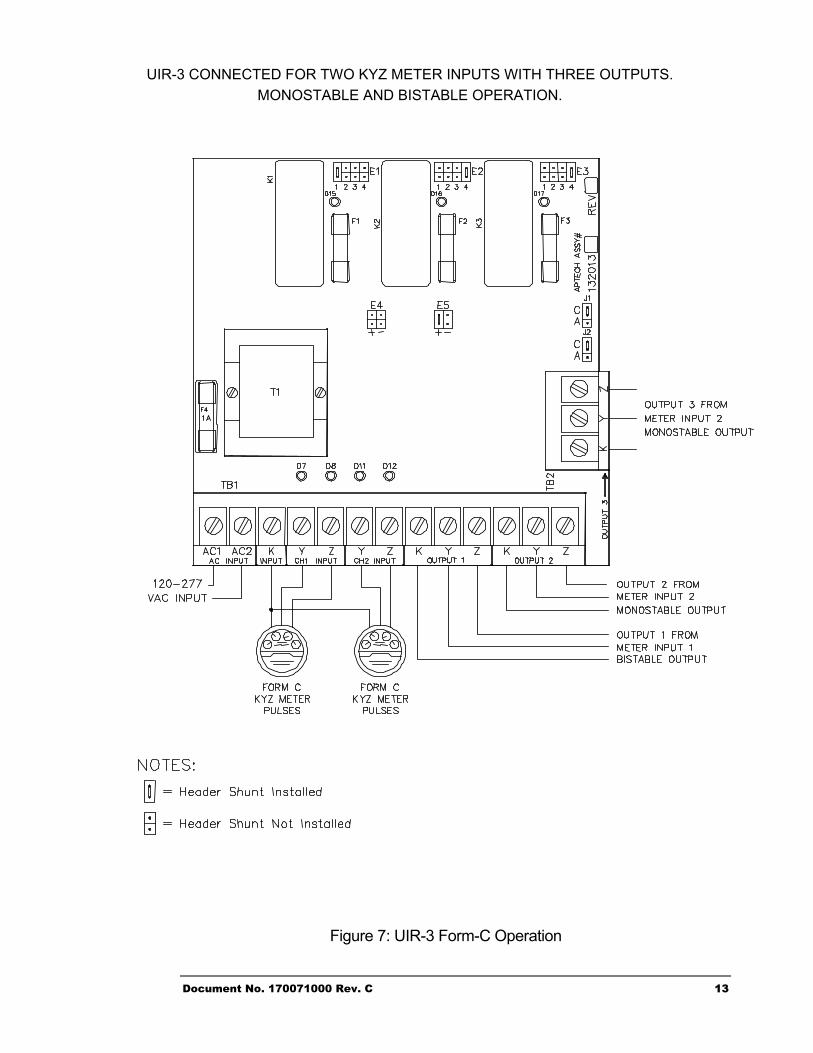
UIR-3 CONNECTED FOR TWO KYZ METER INPUTS WITH THREE OUTPUTS. MONOSTABLE AND BISTABLE OPERATION.
Figure 7: UIR-3 Form-C Operation
Document No. 170071000 Rev. C 13
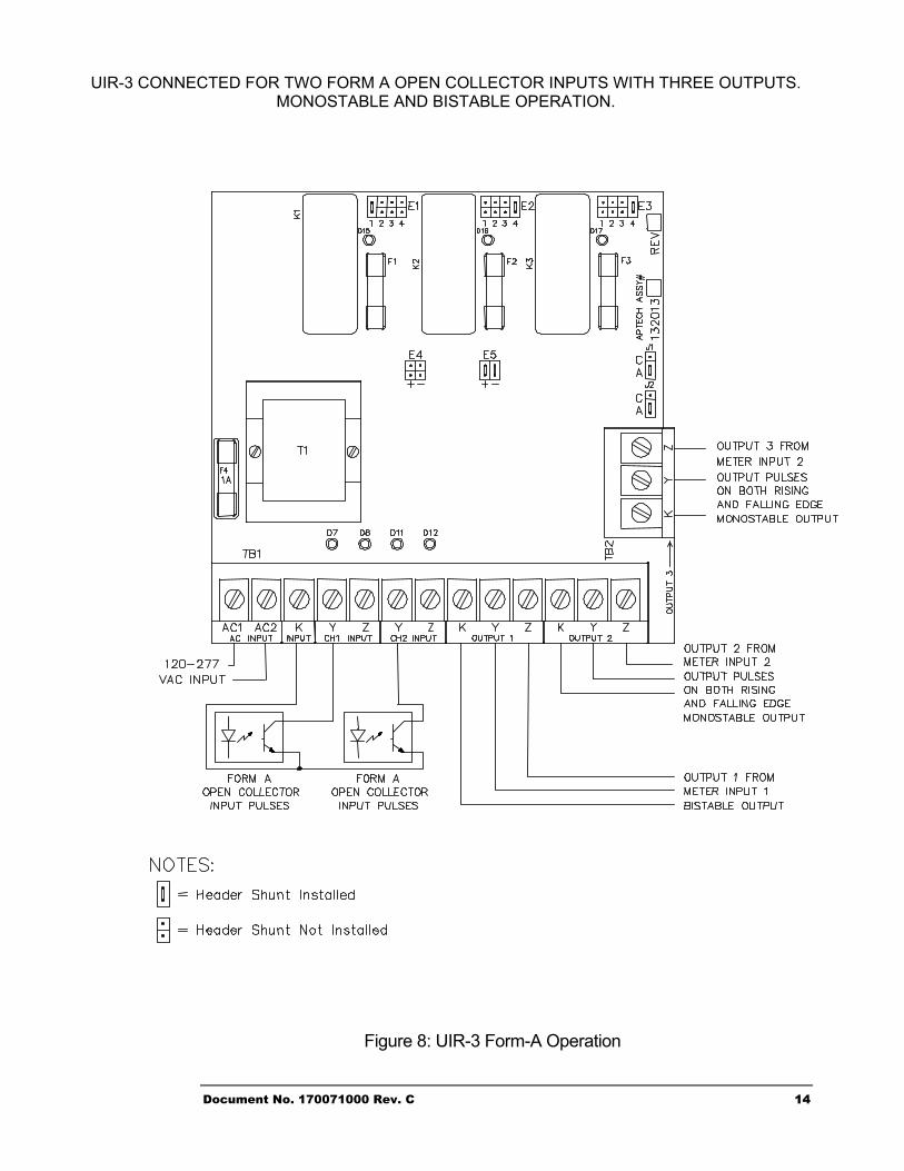
UIR-3 CONNECTED FOR TWO FORM A OPEN COLLECTOR INPUTS WITH THREE OUTPUTS. MONOSTABLE AND BISTABLE OPERATION.
Figure 8: UIR-3 Form-A Operation
Document No. 170071000 Rev. C 14
Document No. 170071000 Rev. C 15
Troubleshooting
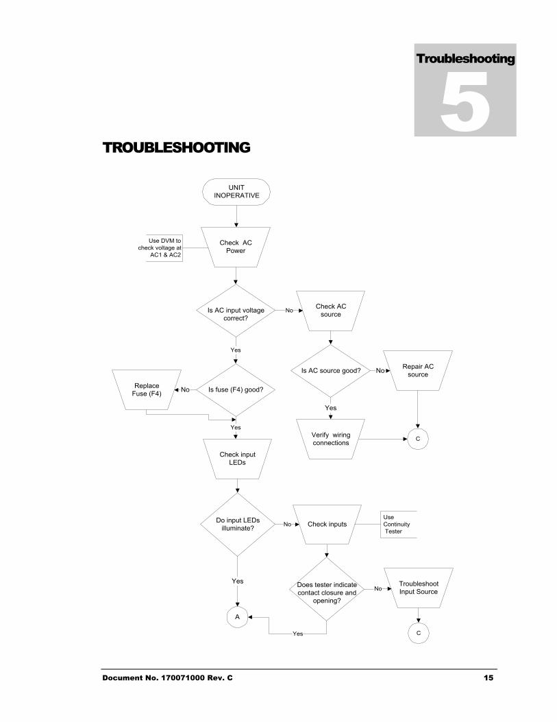
5 TROUBLESHOOTING
UNITINOPERATIVE
Check ACPower
Is AC input voltagecorrect?
Check ACsource
ReplaceFuse (F4) Is fuse (F4) good?No
Verify wiringconnections
Is AC source good?
Yes
Repair ACsourceNo
Check inputLEDs
Yes
A
Yes
Use DVM tocheck voltage at
AC1 & AC2
Yes
No
Does tester indicatecontact closure and
opening?
TroubleshootInput SourceNo
C
Do input LEDsilluminate? Check inputs
UseContinuity Tester
No
Yes
C
Document No. 170071000 Rev. C
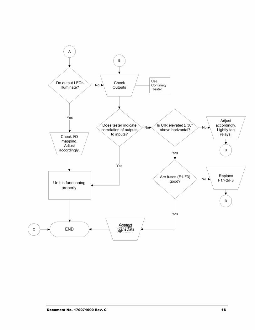
END
A
CheckOutputs
Yes
Is UIR elevated ≥ 30ºabove horizontal?
Adjustaccordingly.Lightly tap
relays.
NoDoes tester indicatecorrelation of outputs
to inputs?
No
Are fuses (F1-F3)good?
Yes
ReplaceF1/F2/F3No
B
B
C
Unit is functioningproperly.
Do output LEDsilluminate?
UseContinuity Tester
No
B
Yes
Yes
Check I/Omapping.
Adjustaccordingly.
a
ContactContact TransDat
16
TECH
AP
Document No. 170071000 Rev. C 17
Specifications
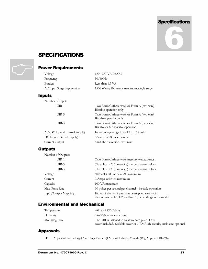
6 SPECIFICATIONS
Power Requirements Voltage 120 - 277 VAC ±20% Frequency 50/60 Hz Burden Less than 1.7 VA AC Input Surge Suppression 1500 Watts/200 Amps maximum, single surge
Inputs Number of Inputs
UIR-1 Two Form C (three-wire) or Form A (two-wire) Bistable operation only
UIR-5 Two Form C (three-wire) or Form A (two-wire) Bistable operation only
UIR-3 Two Form C (three-wire) or Form A (two-wire) Bistable or Monostable operation
AC/DC Input (External Supply) Input voltage range from ±7 to ±65 volts DC Input (Internal Supply) 5.5 to 8.5VDC open circuit Current Output 5mA short circuit current max.
Outputs Number of Outputs
UIR-1 Two Form C (three-wire) mercury wetted relays UIR-5 Three Form C (three-wire) mercury wetted relays UIR-3 Three Form C (three-wire) mercury wetted relays
Voltage 500 Volts DC or peak AC maximum Current 2 Amps switched maximum Capacity 100 VA maximum Max. Pulse Rate 10 pulses per second per channel – bistable operation Input/Output Mapping Either of the two inputs can be mapped to any of
the outputs on E1, E2, and/or E3, depending on the model.
Environmental and Mechanical Temperature -40° to +85° Celsius Humidity 5 to 95% non-condensing Mounting Plate The UIR is fastened to an aluminum plate. Dust
cover included. Sealable cover or NEMA 3R security enclosure-optional.
Approvals • Approved by the Legal Metrology Branch (LMB) of Industry Canada (IC), Approval #E-244.
Index
7 INDEX
A Applications........................................................................ 2
E Electrical Hardware ............................................................ 3
F Features ............................................................................. 2 Functional Description........................................................ 3
H Headers E1, E2, & E3 ........................................................ 5 Headers E4 & E5 ............................................................... 6 Headers J1 & J2................................................................. 5
I Input Configuration............................................................. 5 Input/Output Mapping......................................................... 5 Inputs ................................................................................. 3 Installation Instructions....................................................... 1
M Mechanical Hardware ........................................................ 3 Meter Input Wiring.............................................................. 4 Models................................................................................ 2
O Output Mapping.................................................................. 5 Output Wiring ..................................................................... 4 Outputs............................................................................... 3
P Power Supply ..................................................................... 4
S Specifications ................................................................... 17
T Troubleshooting ............................................................... 15
U Unpacking.......................................................................... 1
W What is a UIR?................................................................... 2 Wiring Connections............................................................ 4
Document No. 170071000 Rev. C 18