Embed Size (px)
Citation preview

uI 1980 EDITION
ELECTRON î
ELÉECTD ÁT Q
Q
CORE A PROJECT BUILDER'S
BULLSEY Portable Anytime Flasher rim Three -Dial Combo Lock 5 : Equipment Protector 12 , 1F EasyTouch Switch
nf Monitor 9 e .t \ luid Detector 14 11/4
rain Teaser fight Latcher - igMoose Call 8 \ l 10 asic NOR Gate 1\1/4
omThumbTimer 1,15 Solar Metronome - emote Thermometer 19 ,aj 2 ó Phototoch Adaptor
O IC Projects for orne and Workbench
o
71 486 022
05
72 Of A DAVIS. PAM 1CAI ON

Now get OHIO SCIENTIFIC personal computer products with guaranteed, quick, mail order delivery.
ONLY 5279
Ohio Scientific Superboard II The first complete computer system on a board Includes keyboard, video display and audio cassette nterf ace 8K BASIC -in -ROM, 4K RAM Requires power supply + 5V at 3 Amp
"We heartily recommend Superboard II for the beginner who wants to get into microcomputers with a minimum cost. A real computer with full expandability." POPULAR ELECTRONICS, MARCH, ' 979
"The Superboard II is an excellent choice for the personal computer enthusiast on a budget." BYTE, MAY, 1979
Ohio Scientific CIP Series.
The Challenger 1P. The best bargain in
personal computer anywhere! 8K BASIC -in- ROM 4K RAM Cassette based with 53 -key keyboard B &W video display, 30 rows x 30 columns Upper and lower case. $349. C1P with 8K RAM $399
Ohio Scientific CIP MF. Mini -floppy version of the Cl P 8K BASIC -in -ROM, 12K RAM. Fully expandable $995. Cl P MF with 20K RAM and OS -65D software $1198.
SOFTWARE Cassettes MOMS Personal
Add Game 8 6.C10 Calendar /Address
BASIC Tutor Series Book $29.00 829.00 Home Control II
Function Grapher $29.00 8 6.00 DAC I Music
Address Book Generation 839.00 8 8.00 Baseball I & II, Golf,
Programmable Bowling, Hockey
Calculator $12.00 $39.00 Savings Account Poker, Black Jack,
8 800 Spades, Hearts, more
Baseball I 8 6.00 $29.00 Battleship S 6.00 Tiger Tank, Space
Bowling S 6.00 Attack, Etch -A-
Destroyer $ 6.00 Sketch, more
Space War S 6.00 $29.00 Star Trek 8 6.00 Star Wars, Zulu 9,
Tiger Tank 812.00 High Noon. more $29.00
Disks Monster, Kite, Three MOMS Education Little Pigs, Humpty System $28.00 Dumpty and more MOMS Aux File [2 Disk Set) $29.00 Systems $29.00 g eri rd When Whe on, specify
Challenger 1P, 4P n
$29.00 s MDMS Checking and C
Savings Account Cr 8P
Many, many more software systems are available to you See our catalog for complete listings.
AC -3P 12" B/W monitor, -V AC-15P 12" Color monitor AC -16P 2 -8 Axis Joysticks with cable AC-11P Answer /Originate 300 baud modem with cable AC-17P Home Security Starter Set. 1 fire detector, 2 window alarms, 1 door unit. AC-18P 81/2" aluminized paper printer. Upper /lower case. AC -9TP Centronics 799 11 Ocps tractor feed, business printer with interface AC-12P AC- Remote starter set. Console 2 lamp modules, 2 appliance modules, OS 65D home control operating system Disk Drives CD 3P Single 5" mini floppy CD 2P Dual 8" Disk with irterf ace and OS -650 DOS
Power Supplies PS 1. 5 -volt r z 3 amps regulated. For use with Superboard II
Boards (Assembled and tested) CM 9P. 24K Static. 610. 8K Static. Expandable to 24K and dual mini- floppy controller. CA -14A. Votrax' voice synthesizer. CA -15 Universal Telephone Inter - face, rotary or touch tone CA -15V UTI with Votrax' CM -6 48K Dynamic memory board. 4KP. 4K static RAM kit CA12. 96 line parallel I/O
Books: How to Program Microcomputers, By William Barden $ 8.95 Basic and Personal Computer By Dwyer & Critchfield $12.95
S 125 S 450
S 39
S 199
S 249
S 695
$ 1250
$ 175
$ 499
$ 1599
$ 29
8 399
$ 298
$ 399
8 499 $ 799
8 499 8 89 8 175
Howard Sams Cl P Service Manual S 7.95 Howard Sams C4P Service Manual 515.95
Freight Policies All orders of $100 or more are shipped freight prepaid. Orders of less than $100 please add $4.00 to cover shipping costs. Ohio Residents add 5 5% Sales Tax.
Guaranteed Shipment Cleveland Consumer Computers & Components guarantees shipment of ccmputer systems within 48 hours upon recent of your order. Our failure to ship within 48 hours entitles you to S35 of software, FREE.
CLEVELAND CONSUMER E COMPUTERS & COMPONENTS P.O. Box 46627 Cleveland, Ohio 44146
Ohio Scientific C4P Series.
The Challenger 4P. A 4 -slot computer with one open slot. Highly sophisticated 16 color video display 32 rows x 64 columns, upper and lower case. BK BASIC -in -ROM 8K RAM. 200 -20KHz programmable tone generator. AC remote interface. Expandable to 32K RAM and two mini- floppy drives $688.
The Challenger 4P MF. Mini Floppy version of the 4P. Two to three times faster than competitors. More I/O built -in than any other in its class. 24K RAM Real time clock. Modem interface. Printer interface. Foreground /Background operation and much, much more. $1695.
Ohio Scientific 8P Series.
Challenger BP. Ohio Scientific's mainframe - class. Personal computer 8 slots with 6 open Cassette based with BK BASIC -in- ROM 8K static RAM, expandable to 32K RAM, and dual 8 -inch floppy disk drive $895.
Challenger 8P DF. A top of the line personal and small business computer 32K RAM, expandable to 48K. Features dual 8" floppy disk drives Audio output 200 20KHz. DAC for voice generation Keypad interfaces. Joystick [2] interfaces. AC Remote Real Time Clock. Printer & Modem interfaces. And more $2597.
To Order: Or to get our free catalog CALL 1- 800 -321 -5805 TOLL FREE. Charge your order to your VISA or MASTER CHARGE ACCOUNT Ohio Residents Call (216) 464 -8047 Or write, including your check or money order, to the address listed below
Hours: Call Monday thru Friday 8:00 AM to 5.00 PM E.S.T.
6ISA
TO ORDER: CALL
1- 800 -321 -5805 TOLL FREE
CIRCLE 14 ON READER SERVICE COUPON

nnovation The sharpest picture ever achieved in big -screen projection TV The new Heathkit Screen Star sets a new standard in picture quality for big- screen projection TV. The finest F1.0 lenses you can buy produce one of the clearest, brightest pictures ever. Imagine watching all your favorite TV movies and sports events on a big 6 -foot diagonal screen. Heathkit's three -tube projection gives you brighter, more vivid color. And its a lot easier to build than conventional TV's.
A complete computer system in one compact unit The Heathkit All -In -One Computer takes the guesswork out of selecting a bal- anced computer system. It includes built -in floppy storage, smart terminal, heavy -duty keyboard, 12 -key numeric pad, Z80 CPU, and 16K RAM expandable to 48K -all in one compact unit. Two Z80 microprocessors mean ter- minal and computer never share power. So both can operate faster on more complex programs. And there's no better way to learn about computers than to build one yourself.
The only computerized home weather station for instant, up-to-
the-minute weather reports Just push a button for reliable weather information anytime you need it with the unique Heathkit Weather Station.
It gives you digital readouts of F or C temperatures, wind speed in
miles or kilometers per hour or in knots, wind direction, barometric
pressure, date and time of day, even the wind chill factor.
This microprocessor -based weather computer has memory to store data
and precision infra -red sensing devices built into the outdoor trans-
mitter. And it's very easy to build.
The finest stereo receiver ever introduced by one of the
leaders in audio technology Its loaded with luxury features that
let you adjust your music to your preference.
Special features include a Precision Tuning System (PTS) that automati-
cally corrects mistuning. 5- section FM tuning capacitor gives you maximum
rejection of unwanted signals for lower noise, cleaner sound. Digital frequency
readout, center tune meter, and flywheel loaded tuning are just a few of the lux-
ury touches. Complete specifications are in the latest Heathkit Catalog.
FREE CATALOG See all the newest innovations in build -it- yourself kits in the latest free Heathkit Catalog. It contains nearly 400 exciting kits for your home, work or pleasure. Send today.
Heathkit If coupon is missing, write Heath Co.,
Dept.174 -632. Benton Harbor, MI 49022
Heathkit Products are also sold and serviced at Heathkit Electronic Centers (units of Veritechnology Electronics Corporation) in major cities throughout the U.S. See your white pages.
r Send to: Heath Company, Dept. 174 -632.
Denton Harbor, MI 49022 Yes, please send me a Heathkit Catalog. I am not currently receiving your catalogs.
Name
Address
City
CL -725A
State
Zip
CIRCLE 1 ON READER SERVICE COUPON

101 Electronic Proects 1980
1 Moose Call 20 2 Shaped Output Code Oscillator 20 3 Zener Diode Tester 21 4 Fluid Detector 22 5 Basic NOR Gate 22 6 General Purpose Pulser 22 7 MOS -to -TTL Logic Interface 23 8 Constant Current Ohms Adapter 23 9 Low Pass Audio Filter 24
10 Portable Emergency Flasher 25 11 Equipment Theft Alarm 25 12 Vari -Rev Motor Control 25 13 Capacitance Oscillator 26 14 Home Made NPO Capacitor 26 15 Photoflood Dimmer #1 27 16 Square Wave Converter 27 17 The Brain Teaser 27 18 EVM Timing Adapter 28 19 Phototachometer Adapter 28 20 Low -Power Dummy Load 28 21 The Light Latch 29 22 Battery Monitor 29 23 Simple Pulse Circuits 29 24 Solar- Powered Metronome 30 25 Record Restorer 30 26 Three -Dial Combination Lock 31 27 Microcomputer 'AC Interface 31 28 Hi -Temp Alarm 31 29 Simple Touch Switch 32 30 Cigar Lighter Power 32 31 Tom Thumb's Timer 33 32 Bounce -less Digital Switch 33 33 Multivibrator Tone Hummer 38 34 Basic Color Organ 38
35 Nine Volt Neon 36 Scope Calibrator 37 Blinking Neon Night Light 38 Lo Hum Power Supply 39 Scratch Filter 40 Noise Generator 41 Budget Lamp Dimmer 42 High Performance Transistor
Radio 43 Wire Tracer 44 Poor Man's Hold Switch 45 Transistor Squelch 46 Stereo Beat Filter 47 Sidetone Oscillator 48 Idiot's Delight 49 Fox Hunt Transmitter 50 Disguised CB Antenra Matcher 51 Crystal Checker 52 Quick Draw Game 53 12 to 9 for Transistors 54 Audio Utility Amp 55 Attache Alarm 56 Pro Burglar Alarm 57 Square Wave Generator 58 Latching Burglar Alarm 59 Wide Range Voltage Pilot 60 Dry -Cell Charger 61 Photoflood Dimmer #2 62 Voltage Controlled Oscillator 63 Highway Nightfall Alert 64 Transistor Checker 65 Angler's Bite Booster 66 Turn On Delay 67 VOM Thermometer
38 39 39 40 40 41 41
42 42 42 43 43 44 44 45 45 46 46 46 47 47 48 48 49 49 49 50 50 50 51
51 52 52
68 Overvoltage Protector 69 High Impedance Mike Amplifier 70 Zener Regulator 71 Balanced Mike Preamp 72 Doorknob Security Alarm 73 The Bamboozler 74 Rocker's Mike Booster 75 Twang -A -Matic 76 Computer Attenuator 77 Current Tattletale 78 Speaker -MIC 79 Quick Diode Checker 80 Power Torque Control 81 Photo Print Meter 82 LED Bar Graph Display 83 555 Switch Hitter 84 Easy Headlight -On Warning 85 CB Scope Monitor 86 Wrong -Way Battery Protector 87 SWL's Low Band Converter 88 Photoelectric Tattletale 89 Flash Tester 90 Sensitive Squelch 91 Pencell NiCad Charger 92 Level Detector 93 Wet Basement Alarm 94 Automobile Ignition Maze 95 AC Adapter 96 Slide Show Stopper 97 LED Telephone Ring Indicator 98 Tone Control Network 99 Remote Flash Trigger
100 Signal -Operated Switch 101 Remote Thermometer
40 INTEGRATED CIRCUIT PROJECTS
1 The CMOS Robot Ear 67 2 Slot Car Race Referee 67 3 IC Audible Logic Probe 68 4 Super Stethoscope 68 5 Variable Regulated Power Supply 71 6 Jogging Pacesetter 71 7 Sobriety Tester 71 8 Top Octave Divider 72 9 The Waveshaper 72
10 Electrolytic Capacitor Tester 72 11 SST Function Generator 73 12 Plant Moisture Meter 74 13 Random Sequence Generator 74 14 Video Pattern Generator 75
Wire Wrap Breadboarding 87 Designing Regulated Power Supplies 90 Pulstar 94
New Products
15 Featherweight Foghorn 75 16 Active Low Pass Filter 76 17 Alternator Monitor 76 18 The Whistler 77 19 One or Two -Way Reflex Tester 77 20 Single Supply Signal Shifter 78 21 Simple RF Generator 78 22 Pennypincher's Frequency Meter 79 23 Antenna Bearing Indicator 79 24 Touch -Activated Combination
Lock 80 25 The Optical Oracle 80 26 LED Black Jack 81 27 The Howler 81
SPECIAL FEATURES Count Capacita The Smart Power Supply Mini -Reg
28 Crystal- Controlled TTL 29 Sawtooth Sounds 30 Hands Off! 31 Mini -Micro Metronome 32 Musical Modulator 33 Dividing It All Up 34 The TTL Robot Ear 35 Mini - Modern Crystal Receiver 36 Multi -Input Music Synthesizer 37 Mini -Digital Roulette 38 Guitar Tuning Aid 39 Digital Modulator 40 TTL Logic Próbe
97 Diode Digest 101 The Fine Art of Buying Parts 103 Junk Box Special
OUR REGULAR DEPARTMENTS 4 Literature Library
Ask Hank 116 115 Classified Ads
52 53 53 54 54 55 55 56 56 56 57 57 58 58 58 59 59 60 60 60 61 61 62 62 62 63 63 64 64 64 65 65 66 66
81 82 82 82 83 83 84 84 85 85 86 86 86
106 107 111
117
2 101 ELECTRONIC PROJECTS 1980

1057 -192 p.-All About Telephones (S7 951
65*If COUNT; CS ONE BOOK- , 604 88250E p Useng floc
borie Testtra for Autortoliee w Tune -Ue & Transistor Ign.
(i, bon Sy. ten (516 90 Mr -'1
An Extraordinary Offer to introduce you to the benefits of Membership in
ELECTRONICS BOOK CLUB take any
(up to 9 books) of these 24 S 99 for unique electronics selections ALL (values to $11155) for only SIX
with a Trial Membership in the Book Club that guarantees lo
save you 25% to 75 °% on a wide selection of electronics books
1120 128 p OSCAR The -.n Ham Radio Salelhles (58 951 8 1169.504 p The GIANT i
GA 87 Handb0Oh 01 Computer Pro
T S Q`ORRy Etaoüv touts (515951
satellites
1241.238 p - cow to B. i1d Your Own Self -Programming Robot (312 95)
ti
COUNTS AS ONE BOOK 861 905-546 p.- Display Electromcs 6 Budd -II Book of Digital Electronic Tome. pieces 1518.90)
1101546 p -How to Design 6 Build Your Own Custom TV Games (514.951
6277-592p -TWO BOOKS II ONE BINDING -Practical Trr uble- shooting With the Modern Oscil- loscope 6 Practical Troubleshoot. ono With Modern Electron.. Test Instruments (525 901
as GA
COUNTS AS IE BOOK 637628 -
398 p.-Fun With Electrmres 8 Basic Electricity & Beginning Electron -cs (S15 90)
THE COMPLETE MICROCOMPUTER .
SYSTEMS HAMMOCK
1123 -210 p.--he laser _e- perrmenler's Ha tdboo : 151 951
1174.259 p - Model Radio Control 3rd Edition 1517 95, r ^e/NW
1201.322 p -The Complete Microcomputer Sys ems Handbook 1Sí5951
1085266 p. -24 'essed Ready-To -Rue Cane Pro Warns in BASIC (S9 951
952.378 p -Microprocessor Pic. grammeng For Computer Hobbyists (512.95)
714.252 p Radio Asironorn For The Amateur 158 951
1176 -352 p - The Masi., Handbook Or Ali Home Heat- ing Systems Tuneup Re- pair. Ins! 6 Maint 1512 951
1 168.162 p How lo Repel 1152 -266 p - Antenna DIM Refer- Clocks 159951 [ lince Manual-includins dlmen-
- j aeon tables 1512 951
c UM
730.236 gr.-Effective Trou nleshootmg With EVM 6 Scope (SI 95)
1119.532 3. -Co o. TV Tr tu tole Faclbook- Probleme 8 Solution. -4 h Edition (S14 951
Facts About Club Membership The 6 introducory both sslecóons of your choice carry pub-
lishers retail prices of up to $111 55 -hey are yours for only
S 1 99 for all 6 (plus postage /handling) with your Tr al Member-
ship
You will receive the Club Nsws.describing the current Selec-
tions. Alternates, and otter books. every 4 weeks (13.a year)
If you want the Selection do nothing. it will be sent to you
automatically It you do rot wsh to receive the Selection. or If you
want to ceder one of the non, Alternates offered. you simply give
instructions on the reply form (and in he envelope) provided.
and return it to us by the date specified. This date allows you at
least 10 days n which to retsrn the form If, because of late mail
delivery. you do not have 10 days to make a decision and so
receive an unwanted Selection. you May return it at Club ex-
pense ',To complete your Trial Membership. !ou need buy only tour
additional monthly Selections or Alternates during the next 12
months. You may cancel your Membership any time after you
purchase these four books.
All books -including the Introductory Offer -are fully return-
able after 10 days if you're not completely satisfied
Ali books are offered at low Membe- prices, plus a small
postage and candling charge. Continuing Bonus If you continue afte- this Trial Membership.
you will earn a Dlyidend Certificate for every book you purchase
Three Certificates plus payment of the nominal sum of SI.99 will
entitle you to a valuable Book Dividend d your choice which you
may choose from a list melded Members
678.276 p.- Modern Coto munlcatwns Swirching Sys- tems (517.95) 1053.266 p Microprocessor
Cookbook (59 95)
My we send you your choice of 6 of these practi- cal time- and -money- saving book selections as
part of an unusual offer of a Trial Membership in Electronics Book Club?
Here are quality hardbound volumes. each spe- cially designed to help you increase your know -how. earning power. and enjoyment of electronics. What- ever your interest in electronics, you'll find Elec- tronics Book Club offers practical, quality books that you can put to immediate use and benefit.
This extraordinary offer is intended to prove to you through your own experience. that these vers real advantages can be yours...that it is possible to keep up with the literature published in your areas of interest, and to save substantially while so doing. As part of your Trial Membership, you need purchase as
few as four books during the coming 12 months. You would probably buy at least this many anyway. with- out the substantial savings offered through Club Membership.
To start your Membership on these attractive terms, simply fill out and mail the coupon today. You will receive the 6 selections (up to 9 books) of your choice for 10-day inspection. YOU NEED SEND NO MONEY. If you're not delighted, return the books within 10 days and your Trial Membership will be cancelled without cost or obligation.
ELECTRONICS BOOK CLUB, Blue Ridge Summit, Pa, 17214
CIRCLE 4 ON READER SERVICE COUPON
1138224 p --Buyer s Guide to Everythmg Electronic For the Home (59 95) 1128.252 p --How O Make
Home Electricity From Wind Wafer and Sunshine 159951
I1 MO MI MI NI =IN= AM NI I=11111
i , , 1
1
1
1
1
1 1
, , , ,
ELECTRONICS BOOK CLUB Blue Ridge Summit, Pa. 17214 Please open my Trial Membership in ELECTRONICS
BOOK CLUB and send me the 6 selections circled below. I understand the cost of the books I have
selected is only $1.99 for all 6, plus a small shipping
charge. If not delighted, I may return the books within
10 days and owe nothing, and have my Trial Member-
ship cancelled. I agree to purchase at least four
additional books during the next 12 months, after which I may cancel my membership at any -ime.
604/882 637/628 678 714 730 861/905 952 1053 1085 1097 1101
1119 1123 1120 1128 1138 1152 1168 1169 1174 1176 1201 1241 6277
Name _ _ Phone _
Address__ -
City _
State Zip
(Valid for new Members only Foreign and Canada add 15 1 u11 -4'0

New Products Pocket Shortwave Receiver
Measuring only 13/4 x 27/s x 1, the Model EP -8 may be the smallest AM /SW 2 -band receiver. In addi- tion to the standard "broadcast" band (AM), the Model EP -8 re- ceives shortwave frequencies from 3.9 to 12 MHz. Audio output is via
CIRCLE 33 ON READER SERVICE COUPON
MICROCOMPUTER BOOKS HOW TO MAKE MONEY WITH
YOUR MICROCOMPUTER by Townsend & Miller
A guide to ways you can create income in the microcomputer ` t aye. Discusses jf magazine articles, hooks, service ,/S bureaus. repair, soft- /d ware, hardware, con . suiting, retailing and shows. Your microcomputer can return a dividend' 1 54pp.
#257 $8.95
Name Address
Zip Check Master Charge VISA
Card # Expires -
Signature
Include S1 .75 insured UPS 101040 shipping & handling.
TOLL FREE 800 -258 -5477 MON -FRI 9 -5 (in N.H. dial 924 -3355)
FREE CATALOG Over 100 titles from beginner to advanced. Guides, games, business applications, programming texts, much more. Chosen for accuracy, readability.
BITSInc Books to erose the impossible
Box 428, Peterborough, N.H. 03458
CIRCLE 16 ON READER SERVICE COUPON
4
the supplied earphone only and the receiver is powered by two hearing -aid type batteries (in- cluded). The EP -8 has built -in Fer- rite Rod antennas for both bands. Shortwave reception is satisfactory for powerful stations such as the BBC, Radio Canada International, Radio Nederland, Deutsche Welle and others. Priced at $24.95 the Model EP -8 is available from Radios International, P.O. Box 6053, Richardson, TX 75080.
LCD DMM OK A new portable digital multimeter by B &K Precision is compact, pro- tected and shielded against RF interference and retains its accu- racy in RF fields. As a result, the Model 2815 can be used near two - way radios or broadcast trans- mitters up to 450 MHz. A major feature of the 2815 is its protec- tion against accidental overloads on all ranges. Its design will resist damage from momentary over- loads up to 1000 volts DC or AC peak in the Ohms range. Continu- ous ohms protection is +1000 VDC and -450 VDC or 350 VAC. The large LCD readout of the 2815 is designed to be used in bright sunlight. An inexpensive 9 volt alkaline battery powers the unit; low- battery warning- indication is automatic. The B &K- Precision 2815 DMM sells for $150 which in- cludes test leads, built -in tilt
CIRCLE 34 ON READER SERVICE COUPON
stand, detailed operating manual and spare fuses. For additional in- formation, contact your local dis- tributor or B &K- Precision, 6460 West Cortland Street, Chicago, IL 60635.
(Continued on page 6)
THE STAFF
Associate Publisher & Editor -in -Chief
Julian S. Martin, KA2GUN Editor
Alan H. Rose, K2RHK Associate Editor
Lee Lensky, KA2DKT
Associate Editor Paul Margolis
Citizens Band Editor Kathi Martin, KGK3916
Editorial Assistant Cynthia McClean, KBKF3780
Workbench Editor Hank Scott Art Director
Ralph Rubino Associate Art Director
David Pindar Assistant Art Director
Michael Vessio Cover Art Director
Irving Bernstein Art Editor
Delia Nobbs Art Assistant Susan Mahler
Production Director Carl Bartee
Production Manager Carole Dixon
Production Assistant Annette Simon
Newsstand Circulation Director Don Gabree
Classified Advertising Director Rose Wayner
Subscription Circulation Director Robert V. Enlow
Subscription Circulation Manager Eugene S. Slawson
Marketing Director James C. Weakley
President and Publisher Joel Davis
Vice President and General Manager Leonard F. Pinto
Vice President and Treasurer Victor C. Stabile, KBP0881
MPA
101 ELECTRONIC PROJECTS is published an- nually by Davis ,Publications, Inc. Editorial and business offices: 380 Lexington Avenue, New York, N.Y. 10017. Advertising offices: New York, 380 Lexington Avenue, 212-557. 9100; Chicago, 360 N. Michigan Ave., Suite 1022, 312 -346 -0712; Los Angeles: J. E. Pub- lishers' Rep., Co. 8732 Sunset Blvd., 213 -659- 3810. EDITORIAL CONTRIBUTIONS must be ac- companied by return postage and will be handled with reasonable care; however, pub- lisher assumes no responsibility for return or safety of manuscripts, artwork, or photo- graphs. All contributions should be addressed to the Editor -in- Chief, 101 ELECTRONICS PROJECTS: 380 Lexington Avenue, New York, N.Y. 10017. Copyright 1980 by Davis Publica- tions, Inc.
101 ELECTRONIC PROJECTS 1980

ITEM NO. CMOS SAFE
"7 IC INSERTION/EXTRACTION KIT MOS -1416 14-16 CMOS SAFE INSERTER
EX -1 14 -16 EXTRACTOR KIT INCLUDES MOS -2428 24 -28 CMOS SAFE INSERTER
EX -2 44 -40 CMOS SAFE EXTRACTOR MOS-40 36-40 CMOS SAFE INSERTER
OK MACHINE & TOOL CORPORATION 3455 CONNER ST., BRONX, N.Y. 10475 U.S.P.
PNONE 1212) 994 6600 TELEX NO 12 5091
PRINTED IN U
MOS-2428
M OS-1416 MOS-40
N4
WK -7 I COMPLETE IC INSERTER /EXTRACTOR KIT [ $29.95 j
INDIVIDUAL COMPONENTS I
MOS -1416 14 -16 PIN MOS CMOS SAFE INSERTER $ 7.95
FMS -2428 24 -28 PIN MOS CMOS SAFE INSERTER $ 7.95
MOS -40 36 -40 PIN MOS CMOS SAFE INSERTER $ 7.95
EX -1 14 -16 PIN EXTRACTOR TOOL $ 1.49
EX -2 24 -40 PIN CMOS SAFE EXTRACTOR TOOL $ 7.95
MINIMUM BILLING $25.00. ADD SHIPPING CHARGE $2.00. NEW YORK RESIDENTS ADD APPLICABLE TAX.
OK MACHINE & TOOL CORPORATION 3455 CONNER ST.. BRONX, N.Y. 10475 (212) 994 -6600 /TELEX 125091
CIRCLE 8 ON READER SERVICE COUPON
101 ELECTRONIC PROJECTS 1980 5

r
P-R-OJECT YOURSELF
Project yourself into a world of electronics fun with these two enterprising books;
Weekend Projects For The Radio Amateur, uol. 1
and Learning To Work With In- tegrated Circuits
You'll Need No fancy tools No special skills No big investment
You'll Get Hours of fun Practical experience Useful equipment
Enjoy and learn while you build. Pick up your copies today; at your local electronics dealer or direct from ARR L.
ORDER FORM ( ) Weekend Projects For The
Radio Amateur, vol. 1 $3.00
( ) Learning To Work With Integrated Circuits $2.00
Selected from the pages of QST Add $.50 each price outside the United States ( ) My check for $ is enclosed ( ) Charge my Visa or Master
Charge
Name -
Address
City State
Zip Visa or MC account number
Expiration date
MC Bank no
6
AMERICAN RADIO RELAY LEAGUE
225 Main Street Newington, CT 06111
CIRCLE 11 ON READER SERVICE COUPON
New Products (Continued from page 4)
Organ in Kit Form Automatic chords and rhythms, al- ternating and walking bass, har- monic memory, multiple arpeg- gios, and many other space -age musical effects identify the new Schober Showman Automatic Electronic Organ. The organ kit contains every needed part plus non -technical step -by -step instruc- tions for both building and play- ing. Assembly time is estimated at about 30 hours. The Showman contains two separate keyboards -the upper carries melody (and right -hand harmony if the player wishes), while the lower controls harmony, automatically or manu-
CIRCLE 35 ON READER SERVICE COUPON
ally. Three pedals modify one - finger- selected automatic chords to produce a total of 60 different harmonies. Five melody voices, in- cluding a wah -wah instrument, can be used alone or mixed. De- layed, regular, and wah -wah vi- bratos are provided. The Shober Automatic Electronic Organ Kit, priced at $650 (bench included). is available from The Schober Or- gan Corporation, 43 West 61st Street, New York, NY 10023.
Mobile Disguise Antennas Antenna Incorporated has a new line of Mobile Disguise Antennas that are visually indistinguishable from standard broadcast anten- nas. The Mobile Disguise Anten- nas are available in two mounting configurations, old style or stand- ard universal cowl mount, for either the single band or combina- tion AM /FM land mobile models. A special matching harness is in- cluded with either model. Offered
in three frequency ranges -25 -54 MHz, 130 -174 MHz and 406 -512 MHz -the Disguise Antennas are factory tuned to the frequency the customer specifies. Maximum power is over 150 watts for the single band model, or 100 watts for the combination AM /FM land mobile model. The radiation pat- tern is essentially omnidirectional,
CIRCLE 36 ON READER SERVICE COUPON
J v depen ent on vehicle and mount- ing location. VSWR is 1.5:1 or less. The standard mount is priced at $47.07. For further information on the Mobile Disguise Antennas, contact Antenna Incorporated, 26301 Richmond Road, Cleveland, OH 44146.
9 -Digit Frequency Counter A unique 50 Hz to 550 MHz nine digit Frequency Counter is now available from DSI Instruments. Called the 5600A, it combines a 10 MHz Proportional -Oven Time Base accuracy of 0.2 PPM, from 10° C to 40° C, with a 10 mV sen- sitivity and resolutions to 0.1 Hz. Its large character, 0.5 inch high
CIRCLE 37 ON READER SERVICE COUPON
9 -digit LED array -with automatic zero blanking -provides enhanced readability at a distance and at wide viewing angles, even under high ambient light conditions. Two input channels are provided. One covers the 50 Hz -to -50 MHz range while the other is for the 50 MHz - to -550 MHz frequency spectrum. The user can quickly select a de- sired resolution from 0.1 Hz to 1.0 KHz with convenient push- button
101 ELECTRONIC PROJECTS 1980

ease. Additional features include an RF pre -amplifier and a 550 MHz prescaler. In 95% factory as- sembled kit form, the instrument sells for $149.95. For additional information, contact DSI Instru- ments, Inc. at 9550 Chesapeake Drive, San Diego, CA 92123, or call toll free by dialing 800 -854- 2049. In California: 800 -542 -6253.
Glass- Mounted Antenna A 5/8 wave mobile antenna by Avanti especially designed for CBers is called Moon -Fantom. The device operates as a true 5/8 wave antenna, yet can be conveniently mounted on glass without tools in a matter of minutes. There are no holes to drill; no car body patch- ing at resale time. Since no ground plane is required, the Moon -Fan- tom has a better radiation pattern than other mobile antennas. Ex- clusive co- inductive coupler at-
CIRCLE 38 ON READER SERVICE COUPON
taches to the opposite side of the windows and establishes a highly tuned circuit to transmit and re- ceive radio frequency directly through glass. A new aerospace adhesive discovery, which has the strength of a 1/4 x 20 metal bolt, bonds the mounting foot securely to glass and both whip and mount can be adjusted to any glass an- gle. It sells for $39.95. or more information, contact Avanti Re- search and Development. Inc., 340 Stewart Ave., Addison, IL 60101.
Aero Band Pocket Scanner The Bearcat pocket -size scanner radio is capable of receiving both the VHF -AM aircraft channels and UHF -FM channels. Airport offi- cials, operating personnel, pilots and others interested in airport operations can now carry a radio which will keep them informed of both tower -to -plane and ground
101 ELECTRONIC PROJECTS 1980
control communications. This Bearcat Aircraft scanner weighs a mere 10 ounces, and is capable of receiving up to 4 channels in any mix of the two bands covered
CIRCLE 39 ON READER SERVICE COUPON
with by- passing built -in. A flexible "rubber ducky" antenna is sup- plied, but the radio can also be used with a wire antenna. The Thin Scan is priced at $149.95 (less crystals and batteries), and is a companion to the "Bearcat 220" scanner introduced earlier this year. The Bearcat 220 is de- signed for desk -top or vehicle in- stallation and has 20 channels which can be programmed by key- board entries. It is also capable of receiving VHF -AM aircraft and UHF -FM ground control communi- cations, as well as scores of other services on low and high VHF, UHF -T and amateur bands. Corn - plete information on the Bearcat Thin Scan Aircraft scanner is available from Bearcat scanner suppliers or directly from Electra Company, P.O. Box 29243, Cum- berland, IN 46229.
Automatic Wire -wrapping The new BW -2630 by OK Machine and Tool is a revolutionary wire - wrapping tool which operates on 2 standard C -size NiCad batteries (not included) and accepts either of two specially designed bits. Bit model BT -30 is for wrapping 30 AWG wire onto .025 -inch square pins; BT -2628 wraps 26 -28 AWG wire. Both produce the preferred "modified" wrap and are priced at $3.95 and $7.95 repectively. De- signed for the serious amateur, BW -2630 even includes both posi- tive indexing and anti-overwrap- pi ng mechanisms -features usually found only in expensive industrial tools. Pistol grip design and rug -
(Continued on page 9)
FOR 111E
EXPERIMEIUER INTERNATIONAL CRYSTALS and KITS
OF-1 OSCILLATOR
$493 ea.
The OF -1 oscillator is a resistor /capacitor circuit
providing oscillation over a range of frequen- cies by inserting the desired crystal, 2 to 22 MHz, OF -1 LO, Cat. No 035108. 18 to 60 MHz, OF -1 HI, Cat. No. 035109. Specify when ordering. MXX -1 Transistor RF Miser 3 to 20 MHz Cat No 035105 20 to 170 MHz Cat No 035106 SAX -1 Transistor RF Amp 3 to 20 MHz. Cat No 035102 20 to 170 MHz. Cat No 035103 BAX -1 Broadband Amp 20 Hz to 150 MHz. Cat No 035107 $5.67ía.
02% Calibration Tolerance EXPERIMENTER CRYSTALS
86,38 ta.
KW ea
(HC 6/U Holder) 74 ea.
Cat. No. Specifications 031300 3 to 20 MHz - For use In
OF-1L OSC Specify when ordering 031310 20 to 60 MHz - For use ln OF-1H OSC
Specify when ordering
Enclose payment with order no COD ) Shipping and postage (Inside U S Canada and Mexico only) will be prepaid by International
Prices quoted for U S . Canada and Mexico orders only Orders for shipment to other countries will be Quoted on request
Price subject to change Address orders to M S Dept . PO Box 32497
OklahomaCdy. Oklahoma 73132
WRITE FOR BROCHURE
International Crystal Mtg. Co., Inc. lONorth Lee Oklahoma City Oklahoma 73102
CIRCLE 6 ON READER SERVICE COUPON
r ur CB BOOKS -+e THE BOOTLEGGERS BIBLE modify any CB for extra channels 23/40 channel, AM /SSB, PLL or Crystal. 95% of all CB radios covered in this single book, silver edition SI4.95. CB RADIO REPAIR for yourself, your friends or profit. Complete manual 3rd edition SI0.95. LINEAR AMPLIFIER PLANBOOK 20, 60, 140 and 300 watt plans $8.00.
Available Now From A.P. SYSTEMS Box 488, Dept. 101CT, Milford, PA 18337
MeeterchergeNlea Phone Orden Accepted T 717 888.5900
CIRCLE 15 ON READER SERVICE COUPON
Birth defects are forever.
Unless you help. THIS SPACE CONTRIBUTED By THE PUBLISHER
7

Lab Test Elementary Electronics
For Yourself
In case you're not all that familiar with us,we're not a publication for electrical engineers and other wizards. No way. ELEMENTARY ELECTRONICS is ex- pressly for people who like to build their own projects and gadgets and maybe get a little knee -deep in tape, solder and wire clippings in the process. In fact, we have a sneaking suspicion that our readers like us because they think we're just as bug -eyed and down- right crazy over great new project ideas as they are. And I guess they're right!
E E thinks of you who dig electronics as the last of a special breed. It's more than just the "do -it- yourself' angle it's also the spirit of adventure. In this pre- packaged, deodorized world, building your own stereo system, shortwave receiver, darkroom timer or CB outfit is like constructing a fine -tuned little universe all your own. And when it all works perfectly it really takes you to another world.
ELEMENTARY ELECTRONICS knows the kinds of projects you like -and we bring 'em to you by the truckload!
Ever hanker to build a sharp -looking digital clock radio? Or to hook up an electronic game to your TV? Or an easy -to-build photometer that makes perfect picture enlargements? Or a space -age Lite -Com so you and the family can talk to each other on a light beam? We've got it all to get you started.
WHEN IT COMES TO REPAIRS E/E can save you time, trouble and a pile of money!
Has your sound system gone blooey just when the party's going great? Do you shudder when your friendly neigh- borhood electrician hands you the bill? E/E can help.
Of course, we can't make you a master electrician overnight. But we can show you the fundamentals of repair plus maintenance tips.
IF YOU'RE NEW TO ELECTRONICS YOU GET A "BASIC COURSE "!
\That's right! It's a regular feature. And 8
Get switched on
it gives you the complete, ground -floor lowdown on a variety of important electronics subjects. For example Understanding Transistors ... How Radio Receivers Pull in Signals... Cathode Ray Tubes Explained ... How Capacitors Work ... Using Magnetism in Electronics. And more!
ENJOY GREAT ARTICLES LIRE THESE
How to Build Your Own Transformer How to Select the Right Shortwave Receiver The Burgeoning World of Micro- computers Quickdraw Rickshaw The Electric Car that Really Gets Around What's Really Wrong with FM Radio? How to Power -Up Your Antique Radio The Vanishing Vacuum Tube How to Customize Your CB Antenna Those Incredible TV Sets of the Future Listening in on the Forgotten Continent DXing Endangered Species Sandbagging CB Fun Without a License The World's Worst Hi -Fi Com- ponents
TRY A FEW ISSUES AND EVALUATE OUR ...
HOW- TO -DO -IT HELP. Tips and pointers that add up to money saved. For example tuning up your tape player ... all about radios ... whys and hows of turntables ... care and feeding of speakers.
I. NO- NONSENSE TESTS. The scoop on Pioneer's TP -900 FM stereo car radio ... How well does GE's NiCad charger pep up your pooped batteries? ...What's ,ç G JQ, your best bet in video games? Plus -f- , ' , ( . 5e e
elementary
at.,,..«.,..M ,.., ,. , Ns/ .,.... , au
l,f
EXCITING DISCOVERIES. What- ever your particular interest in elec- tronics, you'll be entering a world of discovery in the pages of ELEMENTARY ELECTRONICS.
ELEMENTARY ELECTRONICS is regularly $6.95 for 6 issues (one year).
But with this special introductory offer you coin enjoy a full year for only $3.98.
ORDER TODAY
O k
ò a G
4
ewO 0e) \-1"
e G r o help in making buying decisions. e e ' 4 ee v'O\ t0 D1
. ,,( .' Gt h e Kr 0., 0
.Q G
J o+ ,p5 ed e5 e .GoaQ
P ' ,et ce e'(% ., eP.
-te Paá .dF ee
Pd G
/ ,dö°. 0t 9 vc
e`Odt
.4o
,Llah
5ti`e Q\ees°ect 0
101 ELECTRONIC PROJECTS 1980

New Products (Continued from page 7)
ged construction assure perform- ance and durability. Available for only $19.95, the BW -2630 can be purchased at local electronic re-
101411":51i s "w
n
401
0frik ri
l CIRCLE 40
ON READER SERVICE COUPON
tailers or directly from O.K. Ma- chine and Tool Corp., 3455 Conner Street, Bronx, New York 10475.
AC on the Road Two new Micronta Power Inverters by Radio Shack convert 12 VDC to 120 VAC to power AC appli- ances from your car, boat or rec-
CIRCLE 32 ON READER SERVICE
COUPON
reational vehicle battery. The 300 - watt inverter is said to be capable of powering color TV's, electric typewriters, small hand drills, sew- ing machines and many other items requiring no more than 300 watts continuous power. The 100 - watt inverter is suitable for pow- ering small TV sets, electric ra- zors, transistor radios, Amateur and CB two -way radio equipment and other small appliances. Both inverters feature a Normal /Boost switch to provide extra power to compensate for low battery input voltage. The Circuit breaker auto- matically resets 3 -4 seconds after the overload has been removed. Full load input current is given as
101 ELECTRONIC PROJECTS 1980
25 amps for the 300 -watt model; 12 amps for the 100 -watt inverter. The Micronta 300 -watt Power In- verter is priced at $79.95; the 100 - watt Inverter, complete with cig- arette lighter plug is, priced at $39.95. Micronta Power Inverters are available exclusively from par- ticipating Radio Shack stores and dealers, nationwide.
Speaker System Kits Two of KEF's speakers -the Model 104aB and the Cantata -are now available in kit form, enabling the consumer to easily assemble a top quality product at a significant cost -savings. The kits are packed in pairs, with the appropriate drive units and crossover circuits al- ready. mounted, wired and tested on the front baffles. Assembly is simple, requiring only construc-
CIRCLE 42 ON READER SERVICE COUPON
tion of recommended enclosures and installation of the baffles. The 104aB kit ($250) comprises a mid - bass drive unit, tweeter and Acoustic Butterworth filter, and when completed is a closed box loudspeaker system with an im- pedance of 8 ohms and a maxi -
CIRCLE 42 ON READER SERVICE COUPON
mum power rating of 150 watts. Both kits include fuse units to pro- tect the appropriate drive units and contour controls to adjust the acoustic output to match the en- vironment of the listening room. For further information, write to Intratec, P.O. Box 17414, Wash- ington, D.C. 20041.
AMAZING DEVICES
rtl((( PHASERS )))llr PPF1 PHASER PAIN FIELD - This device recently Bevel oped and patented in our labs oS being evaluated by law enforce ment agencies for rial and crowd control It is now available but
soon win come under the lunsd,ctan of weapons and infernal machine control making I unavailable to the publE The device is nand held and looks like a BUCK ROGERS ray gun It is hazar
Clous it not used with discretion PPF1 PLANS $15.00 1PGI INVISIBLE PAIN FIELD GENERATOR - This
amazing simple hand held device is about the size of a pack of
cigarettes and generates a directional held of moderate to inten
hive pain m the lower part et the head up to a range of SC' De
vice is simple and economical to make
1Pß1 PIANS fó.00 1170.11t ALL PARIS $39.50 1120.10 ASSEMBLED &TESTED FOR AtoMAL COMP .. $49.50
LASERS it- RUBY LASER RAY PISTOL - Produces highly intense reC
beam capable of burning A riataidous dev le PI ASS PAF', ',DURCI S $15.00
HIGH POWERED CARBON DIOXIDE BURNING AND CUTTING
Complete plans and all parts sources $15.00 iD STATE iR I.' WAITS wrn Durit in powe suppl
,,n $9.00 Complete vil with co,'moto' $74.Oó
POCKET LASER pulsed visible red plans $7.00 Complete kit $59.50 Also complete pians and parts sources fo RUBY, YAG. NEODYNIUM HeNe ARGON DYE
NITROGEN and many more lasers
SECURITY SNOOPER PHONE - Dial nome or ottice phone
while on vacation actnahng sensitive mike without phone ringing facettent property protection and intrusion device
SNP2 PI A',S $7.00 SNP2K A,I PARTS 149.50 SNP20 -. .H,EDA,DIsIn $89.50 il,,; Rd ,p M'- $6.00
..¡ a... $8.00 ., .. $7.00
$7.00 $6.00
... SI 00
SCIENTIFIC SYSTEMS. Dept Ato Bo. 716
AMHERST N H 03031
CIRCLE 7 ON READER SERVICE COUPON
r Imo- CB BOOKS 1311 7 THE BOOTLEGGERS BIBLE modify any CB for extra channels 23/40 channel, AM /SSB, PLL or Crystal. 950'o of all CB radios covered in this single book, silver edition $14.95. CB RADIO REPAIR for yourself, your friends or profit. Complete manual 3rd edition $10.95. LINEAR AMPLIFIER PLANBOOK 20, 60, 140 and 300 watt plans $8.00.
Available Now From A.P. SYSTEMS Box 488, Dept. 101CT, Milford, PA 18337
Mestercherge/Vles Phone Orders Accepted ZI 717 686.5900
CIRCLE 15 ON READER SERVICE COUPON
N WIFOR Mc G E E'S BIG SPEAKER CATALOG
1001 BARGAINS IN SPEAKERS- PARTS -TUBES -HIGH FIDELITY
COMPONENTS - RECORD CHANGERS
Tape Recorders -Kits -Everything in Electronics
1901 McGee Street, Kansas City, Missouri 64108
9

8 YYMAfYt
New Products Hand -Held 31 DMM
With a choice of either LCD or LED displays, two new VIZ 31/2 digital multimeters provide an accuracy of 0.1% (DCV) with an input impedance of 10 megohms. The LCD model, WD -759, offers the advantage of a visual indica- tion of function (DC or AC volt- age, ohms or amperes) in the display window, as well as the measurement value. The suggest- ed price is only $159. Measure- ment ranges are from 100- micro- volts to 1000 -VDC and up to 600 - VAC; from 0.1 -ohm to 20 -meg- ohms and from 0.1- microamp to 1 -amp, DC and AC. The units also provide for measurement of either high or low power ohms in all ranges, switch selectable. For easy service in the field, there is a 1 -amp fuse, plus spare, located in the rear battery compartment. An optional AC adaptor is avail- able for bench operation. A carry-
$1.75 At Your Newsstand
Software Directory Your complete source of information on computer
games, business and educational software.
Microcomputer Peripherals Check out an inexpensive
data storage "wafer" that may make cassettes a
thing of the past. Tape digitizers that give you tape
copies that surpass the originals. And much more to
make a great hobby.
Programming Find out about PASCAL, the microcomputer langauge
of the future. Big new BASIC program section.
ON SALE JUNE 5, 1980
10
ing case is available that permits use of the instrument while in the case. Another optional accessory is a high -voltage probe (50 -KV DC). The LED model, WD -758, is
CIRCLE 48 ON READER SERVICE
COUPON
Vlz. WD 759
identical in electrical performance except that it doesn't provide function indication in the display. Price for this model is only $149. For additional details, contact any VIZ distributor or write to VIZ Mfg. Co., 335 E. Price St., Phila- delphia, PA 19144.
Electronic Keyer The new MFJ -408 Deluxe Elec-
tronic Keyer II has a readout me- ter and a socket for Curtis acces- sories. The MFJ -408 lets you read your sending speed to 50 WPM, and the accessory socket allows you to use the following Curtis accessories: external memory, random code generator, or key- board. (These are accessory PC boards or boxes.) The MFJ -408 is based on the proven Curtis 8044IC keyer chip, and sends iambic, au- tomatic, semi -automatic, or man- ual CW. Dot -dash memory pro- vides self -completing dots and dashes with jam proof spacing.
CIRCLE 43 ON READER SERVICE COUPON
The MFJ -408 provides solid state keying for grid block, cathode or solid state transmitters (- 300 -V, 10 -ma. max, +300 -V 100 -ma. max). The MFJ -408 is completely porta- ble; it operates up to 1 year on 4 C -cell batteries. It has a 2.5 mm phone jack for external power (6 to 9 -VDC) or order the optional AC adapter for $7.95. The MFJ - 408 Deluxe Keyer II is available
from MFJ Enterprises, Inc. for $79.95 plus $3.00 shipping and handling, accessory cable with plug is $3.00. To order call toll free 1- 800 -647 -1800 or mail order to MFJ Enterprises, P.O. Box 494, Mississippi State, MS 39762.
Custom Mount The new Model K -4A -DD Fire -
stik Super Stud Disco -Disc Mount uses a chrome -plated steel disc for strength and beauty. It comes complete with SO -239 base, heavy -duty mounting stud and 3/3- 24 solid brass threaded shank. The K -4A -DD accepts PL -259 ter- minated cables: A low- profile deck mount (less than 1 /4 -in. from deck to stud) must be used with spring. The unit is designed to hold
CIRCLE 49 ON READER SERVICE COUPON
heavy duty Firestiks or similar an- tennas up to 4 ft. in length. Excel- lent for use with CB, VHF or ama- teur antennas for installation on trucks, boats, automobiles, RV's, etc. Sells for $5.95. For more in- formation, write to Firestik An- tenna Corporation, 2614 East Adams, Phoenix, AZ 85034.
Wide- Bandwidth Equalizer A new graphic equalizer from
Sansui, with a suggested retail price of just $230, boasts a flat frequency response of 0- 100,000- Hz +0, -1 -dB to ensure that any alteration in frequency balance is limited to changes deliberately made by the listener. The new
CIRCLE 50 ON READER SERVICE COUPON
Sansui SE -5 provides equalization in eight frequency bands, centered on 80, 160, 315, 630 -Hz, and 1.25, 2.5, 5 and 10 -kHz, for precise con -
(Continued on page 114)
101 ELECTRONIC PROJECTS 1980

IN THIS, THE 1980 EDITION OF 101 ELECTRONIC PROJECTS,
we've assembled a truly exciting collection of new cir- cuits for your enjoyment. Each one has been built and
thoroughly tested to insure that it will work exactly as in- tended- provided, of course, that you follow directions pre- cisely and employ good construction techniques. In case
you're unfamiliar with standard construction methods, or nervous about building from scratch," the remaining para- graphs of this introduction are dedicated to you. In them you will find all the tips. techniques and background infor- mation needed for a successful project. Even "old hands" are urged to review this section before building anything; remember. it takes just one forgotten detail to spoil an
otherwise perfect project. Construction Methods. There are three foundations on
which to build an electronic project: a solderless breadboard (SBB), perfboard (with or without wire -wrap) or printed circuitry. Solderless breadboarding is the ideal method when you intend to tear down a circuit after experimenting, or when you wish to see how well a circuit works before com- mitting it to one of the more permanent types of construc- tion. Using an SBB is simplicity itself; just push component leads into the grid atop your SBB, and connect the appro- priate terminals together by inserting jumper wires. Both the wires and the component leads are gripped snugly by contact springs embedded beneath the breadboard's matrix of holes. After experimenting, you can dismantle the circuit by pulling out the components and jumper wires. Almost every major electronics retailer carries some solderless breadboard.
Perfboard and printed circuitry are more permanent methods of construction. Perfboard consists of a sheet of phenolic plastic perforated with a grid of holes, into which small terminals can be inserted. Construction con- sists of mounting terminals in an appropriate pattern, solder- ing component leads to the terminals, and then soldering (or wrapping) wires to interconnect specific sets of termi- nals. Perfboarding is a reasonably quick process that works well with discrete components (transistors, resistors, etc.).
You can use perfboard to mount ICs. but printed cir- cuitry is probably the better method here. That's because it is usually easier to accommodate the closely -spaced pins of integrated circuitry on a PC board. Although printed cir- cuits require more time to lay out and prepare, it's actually easier to mount and solder components on a printed circuit than on a perfboard. Furthermore. a printed circuit is
generally more rugged. and certainly neater than a com- parable perfboard. If you feel a project warrants printed circuit construction, various PC kits are available. The so-
called direct method is the cheapest. making it attractive to beginners. but kits based on photo -sensitive boards are much more versatile and. in the long run, usually a better investment. Both types of kits are widely available.
Component Sources. All the projects presented here can
be built with readily available components; rare birds will not be found roosting in the parts lists. However, don't expect any particular retailer to stock each and every part you need. Local electronics outlets can usually supply basic
items such as resistors. transformers, capacitors. diodes and
cabinets. For transistors, integrated circuits, special devices and the like, your best chance of locating a specific part lies with the mail -order retailers. But here again. not every dealer can be expected to carry all the components you need -especially semiconductors -so shop around.
You may at times be tempted to make component sub-
stitutions. For example, the readily available Motorola HEP S90O1 programmable unijunction transistor makes a good substitute for a 2N6027. However. substitution is a tricky game best played by those with experience. It helps to have
101 ELECTRONIC PROJECTS 1980 11

Electronic Projects full data sheets for both the original part and the intended substitute. Compare all important specifications of the two devices carefully before making a decision. If your substi- tute does not provide adequate performance, you have no one to blame but yourself.
Test Equipment. Expensive electronic test equipment is not required for testing or tune -up of the projects in this book. However, it is wise to have at least a VOM on hand, since it can prove invaluable during troubleshooting. An electronic multimeter with its high input impedance pro- vides even more versatility and accuracy. You can obtain one of these in kit form for around $80. Assuming that your interest in electronics is more than casual, such a meter makes a very worthwhile investment.
DOs and DON'Ts. Here is a brief collection of tips intended to help you sidestep a variety of pitfalls, some shallow and some deep: Use a heat sink when soldering transistors, di- odes and other devices susceptible to damage from heat. Do not solder your ICs; use sockets instead. This makes troubleshooting much less agonizing should it become neces- sary. It also protects sensitive integrated circuits (like CMOS types) from damage due to excessive soldering iron leakage currents. Observe proper device polarities, especially when installing electrolytic capacitors and diodes. Be wary of line - voltage circuitry, especially with Triac projects. If possible, pull the plug when troubleshooting such a circuit. If it must remain "live," at least keep one hand in your pocket when making measurements. This reduces the risk of bridging the power line with your hands, and thereby shorting out a promising career in electronics. Be certain that capacitor working voltages and diode PIV ratings equal or exceed whatever is specified in the parts lists. Audio -taper and linear -taper pots are generally not interchangeable. Use pre- cision components where needed. For instance, suppose that an oscillator is to be built, and that the oscillator's frequency is determined by one resistor and one capacitor. If a 5% re- sistor and a 5% capacitor (i.e., polystyrene or mica) are called for, your oscillator's frequency is likely to deviate no more than ±109 from its intended value. Substituting a 107 resistor and a 20%-tolerance capacitor, you might cause the frequency to vary from its intended value by as much as ±30%, roughly speaking. Certainly there are cir- cuits where such a variation would be inconsequential, but
One of the most important aids in circuit design, construction and troubleshooting is the volt /ohmmeter (VOM). When a circuit doesn't work properly the first time through, a VOM can be used to check voltage levels at any point in the circuit to detect either faulty components or wiring (and PC foil) errors or both.
12
if components with a certain level of precision are specified, be sure to use them for best results. MOSFET transistots can be damaged by static discharge just like CMOS ICs. The surest way to safeguard a MOSFET is by using a socket. Plug the transistor in only after all soldering is complete, and remove its protective shorting wire only after it is securely seated. Note that the junction field -effect transistor (JFET) is much hardier than its MOS cousin, so a socket is not mandatory in this instance.
Interfacing. Most experimenters like to combine circuits together in order to produce customized projects. Ordinarily this is a lot of fun, but problems can arise when you try to interface several stages not inherently compatible with one another. For example, suppose that it's necessary to inter- face circuit A (designed for a 12 -volt DC supply) with circuit B. which operates on 9 -volts DC. We're assuming now that the circuits are both negative -ground (or both positive -ground) and not a mixture of the two. Generally speaking. most projects will function at supply potentials other than those specified, though the performance may he degraded somewhat. A transistor or UJT oscillator might shift to a lower frequency on reduced voltage. while an amplifier stage could exhibit diminished gain under the
A deluxe version of the solderless breadboard, CSC's ProtoBoard has binding posts for bringing in power to the bus strips which run along the outside edges of the breadboard. The heavy base with its rubber feet can allow the builder to work virtually any- where without creating damage to table tops and other furniture.
The ultimate aid in diagnosing flaws in circuitry as well as digi- tal logic errors is the oscilloscope. In the photo above, the oscil- loscope is being used to read the waveform output of a stereo amplifier to detect flaws in the final amplifier which might be the source of distortion. If you can't afford to buy, borrow one.
101 ELECTRONIC PROJECTS 1980

same conditions. However, simple op -amp feedback ampli- fiers and 555 -type oscillators perform with remarkably little influence from supply potentials.
When combining two circuits designed for different sup- ply potentials, it's probably safer to use the lower of the two voltages for the common supply. If the potentials are rea- sonably close, say 12 -VDC and 15 -VDC. performance should be adequate. Should a noticeable frequency shift occur in an RC oscillator, substitute different timing capaci- tor(s) to compensate, if necessary. Circuits with widely separated supply potentials should not be combined. unless you intend to operate each from a separate supply (in which case, make sure the interstage signals are capacitively coupled) voltage source.
You should also make sure that signal levels are com- patible when combining circuits. Feeding too large an input signal to an amplifier stage will cause clipping and distortion, which are undesirable effects in most cases. Exces- sive input levels can be cut down with a simple resistive voltage divider. On the other hand, input signals that are too small may require a stage of preamplification to boost them up to usable levels. Watch your input and out- put impedances, too. If stage A is a signal source and
Printed circuitry offers the most rugged construction format as
well as being the most compact of all available types of construc- tion media. It takes a little more time to build a printed circuit, but the final results are well worth the extra effort and time in- volved in the process. PC kits are available at very low cost.
An adjustable, regulated DC power supply is almost a "must have" item for any circuit builder's bench. As battery prices soar to astronomical levels, the initially greater cost of a power supply becomes more and more affordable. Tight regulation Is
required for TTL IC circuitry and you can only get it this way.
101 ELECTRONIC PROJECTS 1980
stage B is a voltage amplifier, B's input impedance should be several times greater than A's output impedance. However, when it is necessary to transfer the maximum amount of power from stage to stage, A's output impedance should be equal to B's input impedance. Stereo buffs utilize this principle when matching 8 -ohm speakers to an ampli- fier's 8 -ohm speaker outputs.
Interfacing logic circuitry is a task that warrants special attention. CMOS and TTL are the two predominant logic families, and although both types can perform the same logical functions, they differ significantly in several electrical parameters. First, TTL requires a 5 -volt DC supply, while CMOS is content with anything from 5 to 15 -volts DC. Power supplies from TTL must be tightly regulated. while those for CMOS do not always need strict control. Com- paring CMOS at 5 -volts with TTL, note that signals in a
CMOS system should swing above 3.5 -VDC when high, and below 1.5 -VDC when low; by contrast, TTL signals must rise above 2 -VDC in the high state and drop beneath 0.8 -VDC in the low state. So, a 2.5 -volt signal input would be high enough to register as a logical 1 to TTL. but prob- ably not in CMOS. Combine the disparities in logic levels with the fact that most CMOS devices are too feeble to drive standard TTL ICs, and it's obvious that interfacing the two families is a job best left to the experts. Where ap- plicable, we have indicated which projects interface well with CMOS, TTL or both.
Power Sources. Two general power source options are available- either a line- operated supply or batteries. For purposes of experimentation with a number of different cir- cuits, the line -operated supply ought to have an adjustable output, and if it happens to be regulated, so much the better. Batteries can always he series -connected to obtain different potentials. No matter what kind of power source you use, be certain it can handle all the current required by your project. Recommended load currents for some common batteries are as follows: 8 -mA for a 9 -volt tran- sistor batery, 25 -mA for an "AA" penlite cell, 80 -mA for a
"C" cell, and 150 -mA for a "D" cell. Series hookups re- tain the same current capability as a single cell; for example, 8 "AA" cells in series can provide 12 -volts @ 25 -mA. Alka- line types can supply 2 to 3 times more "juice" than stand- ard batteries, and all batteries, regardless of type, can supply much more than the rated current when used on an inter- mittent basis. You can check how much current a circuit is extracting from your batteries by inserting a DC milli - ammeter in series with one of the power leads.
Using a solderless breadboard couldn't be easier -to Install a
component, simply detemine where its leads must go, and then push them down into the proper hole. A spring -loaded grid underneath the board grips the leads tightly to insure good electrical contact, yet allows quick and easy removal as weil.
13
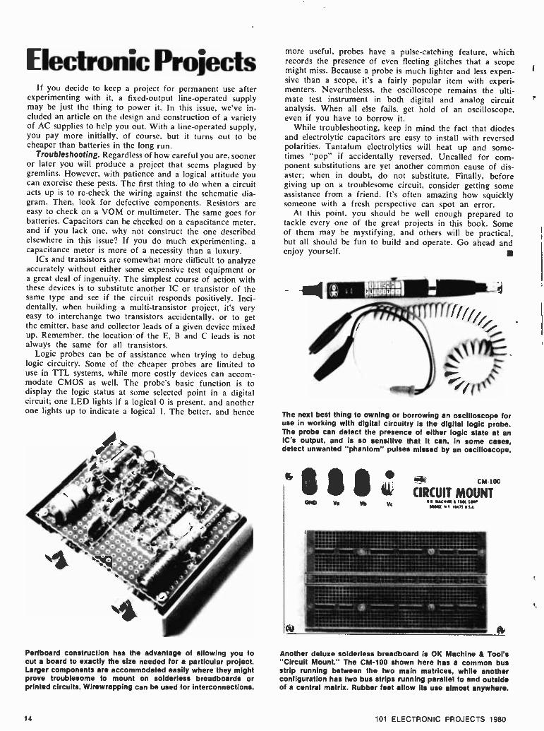
Electronic Projects If you decide to keep a project for permanent use after
experimenting with it, a fixed -output line- operated supply may be just the thing to power it. In this issue, we've in- cluded an article on the design and construction of a variety of AC supplies to help you out. With a line- operated supply, you pay more initially, of course, but it turns out to be cheaper than batteries in the long run.
Troubleshooting. Regardless of how careful you are, sooner or later you will produce a project that seems plagued by gremlins. However, with patience and a logical attitude you can exorcise these pests. The first thing to do when a circuit acts up is to re -check the wiring against the schematic dia- gram. Then, look for defective components. Resistors are easy to check on a VOM or multimeter. The same goes for batteries. Capacitors can be checked on a capacitance meter, and if you lack one, why not construct the one described elsewhere in this issue? If you do much experimenting, a capacitance meter is more of a necessity than a luxury.
ICs and transistors are somewhat more difficult to analyze accurately without either some expensive test equipment or a great deal of ingenuity. The simplest course of action with these devices is to substitute another IC or transistor of the same type and see if the circuit responds positively. Inci- dentally, when building a multi- transistor project, it's very easy to interchange two transistors accidentally, or to get the emitter, base and collector leads of a given device mixed up. Remember, the location of the E, B and C leads is not always the same for all transistors.
Logic probes can be of assistance when trying to debug logic circuitry. Some of the cheaper probes are limited to use in TTL systems, while more costly devices can accom- modate CMOS as well. The probe's basic function is to display the logic status at some selected point in a digital circuit; one LED lights if a logical 0 is present, and another one lights up to indicate a logical 1. The better, and hence
Perfboard construction has the advantage of allowing you to cut a board to exactly the size needed for a particular project. Larger components are accommodated easily where they might prove troublesome to mount on solderless breadboards or printed circuits. Wirewrapping can be used for interconnections.
14
more useful, probes have a pulse- catching feature, which records the presence of even fleeting glitches that a scope might miss. Because a probe is much lighter and less expen- sive than a scope, it's a fairly popular item with experi- menters. Neverthelesss, the oscilloscope remains the ulti- mate test instrument in both digital and analog circuit analysis. When all else fails, get hold of an oscilloscope, even if you have to borrow it.
While troubleshooting, keep in mind the fact that diodes and electrolytic capacitors are easy to install with reversed polarities. Tantalum electrolytics will heat up and some- times "pop" if accidentally reversed. Uncalled for com- ponent substitutions are yet another common cause of dis- aster; when in doubt, do not substitute. Finally, before giving up on a troublesome circuit, consider getting some assistance from a friend. It's often amazing how squickly someone with a fresh perspective can spot an error.
At this point. you should be well enough prepared to tackle every one of the great projects in this book. Some of them may be mystifying, and others will be practical, but all should be fun to build and operate. Go ahead and enjoy yourself.
The next best thing to owning or borrowing an oscilloscope for use in working with digital circuitry is the digital logic probe. The probe can detect the presence of either logic state at an IC's output, and is so sensitive that it can, in some cases, detect unwanted "phantom" pulses missed by an oscilloscope.
CND Va Yc
CM 100
CIRCUIT MOUNT a Y4 ..I t'.11'Jy. enoo u c t 4
Another deluxe solderless breadboard is OK Machine & Tool's "Circuit Mount." The CM -100 shown here has a common bus strip running between the two main matrices, while another configuration has two bus strips running parallel to and outside of a central matrix. Rubber feet allow its use almost anywhere.
101 ELECTRONIC PROJECTS 1980

Solderless Breadboardin
The neat, easy, quick way to go for the experimenter
r
THERE ARE A LOT OF WAYS to put electronic circuits to- gether, among them point -to -point wiring on a chassis with sockets and terminal strips, perf- boards and
printed- circuit boards, to name the most familiar conven- tional methods, all of them depending heavily on soldering. But over the last few years, assembling and testing circuits on solderless breadboards has become increasingly popular. And little wonder, because this technique offers hobbyists and professionals alike a way to save considerable amounts of time, as well as saving sizeable amounts of money, since parts can be used and reused over and over again.
More Work in Less Time. To the electronics professional, engineering and technician time is a valuable resource, and it's really no different for electronics enthusiasts who spend late weekday hours or entire weekends experimenting with new circuits. But how, exactly, is the time spent? With solder in one hand and a soldering iron or gun in the other, which should really be no surprise, when you think about it, since even a simple amplifier can have well over a dozen connections. Add the fact that today's projects, with their 14 -, 16 -, 24- and 40 -pin ICs, multiple LEDs, plus the usual assortment of transistors, capacitors, resistors, potentiome- ter, etc., are often considerably more sophisticated, and your newest labor of love can involve a lot of manual labor.
A Better Way. In their search for a better way to assemble circuits, a number of engineers and technicians came up with crude solderless breadboarding systems, using such ingredients as alligator clips, springs, fahnestock clips perforated masonite, and the like. These were awkward and often unreliable, particlularly when multiple connec- tions were necessary at a given point in the circuit. Hap- pily, like semiconductor technology, solderless bread- boarding technology has come a long way since the early days. Precision and versatility have increased, while prices have decreased to the point that the many advantages of solderless breadboarding are now easily affordable by even the most budget- conscious electronics buff. Today, com- plete solderless breadboarding sockets carry manufac- turer's recommended retail prices as low as $2.50.
With solderless breadboarding, connecting, disconnecting and reconnecting components and leads is nearly as fast and easy as plugging a conventional AC line cord into a wall socket. Just about the only preparation necessary is to strip the insulation from hookup wires, because no con- nectors are required. Leads from all types of components (ICs, transistors, resistors, capacitors, etc.) plug in directly, and interconnect just as easily.
101 ELECTRONIC PROJECTS 1980
We're getting ahead of ourselves. A better way to under- stand the way solderless breadboarding sockets function is
to remember the old days before transistors, when electron tubes plugged into chassis to make things work. Manufac- turers of breadboarding sockets have taken this basic idea and extended it. Instead of round sockets, holes are placed in a rectangular grid, spaced at regular intervals, corre- sponding to the spacing of standard components, such as ICs. And instead of terminating in soldering lugs, the lugs beneath these holes are interconnected in larger or smaller groups. Smaller groups ( usually five or so) , used to con- nect a few component leads together, are called "termi- nals." Larger groups, often of 25, 40 or more, which are used to connect large numbers of leads to a single point in the circuit (such as supply voltage, ground or common signal paths), are called "buscs." By using these terminals and buses, circuits can be easily and quickly assembled in as little as one -tenth the time of conventional t'irine tech- niques. Let's see why.
Figures 1 and 2 illustrate typical solderless breadboard- ing sockets and bus strips used to build and test electronic circuits. As you can see from Figure 3, these can be combined together and "grown" to accommodate virtually any size circuit, using a variety of components
Leads from all components, including DIP (dual -inline
15

Breadboarding package) integrated circuits, are inserted directly into the sockets, and interconnections are accomplished with short lengths of #22 -30 AWG solid hookup wire, stripped of insulation at either end. The result is a neat, compact layout that can be used for testing, or built into a housing.
Adding up the Advantages. By now, if you're like most experimenters who've been exposed to solderless bread- boarding for the first time, you're probably already inter- ested in trying this fun way to build circuits for yourself, just on the basis of the time you'll save. But speed isn't the only nice thing about solderless breadboarding. Here are some of the other major advantages.
You can translate circuits directly from schematic or pictorial diagrams directly to working circuits. There's almost never a need to come up with a separate wiring diagram or go through other intermediate steps. And if you're designing a circuit yourself, you can go from rough sketch right to assembled unit, to check your ideas in minutes. Once you're finished, you can easily translate the working circuit back into a schematic, too.
These are two of the most underrated factors in de- signing and building circuits. On a solderless breadboard, all components are right there in front of you, so it's hard to miswire a circuit. It's also easy to change com- ponent values or connections, especially if you're improv- ing or otherwise modifying a circuit. Component values and parts designations are right there in front of you. And it's rare that you have to move any components to get at others.
Want to add a stage? Feed one circuit into another? Compare two different ways to do things, side -by -side? With modular solderless breadboarding, it's easy. Just keep adding sockets or bus strips as you need them!
Quality breadboarding sockets and bus strips have molded -in mounting holes that let you put them any- where you need them; on a chassis, the surface of a cabinet or workbench. You name it! Be sure the sockets have insulated backing, to prevent shorting if you mount them on metal, or your circuits will be short -lived!
Utilize Your Junkbox. Even components with larger leads can be connected to solderless breadboards by using short lengths of hookup wire soldered to their terminals. And since the better solderless sockets are made of materials that withstand 100 °C or more, you can even use heat -dis- sipating devices in close proximity to the sockets without fear of damage. You can even solder to components while they are still connected to the sockets. Note: consult manufacturers' specifications before you do, though.
For many experimenters, particularly those with tight budgets (and who hasn't one these days ?), solderless breadboarding offers one more advantage that outweighs all the rest. Instead of giving components a lead -length "haircut" each time you use them, components are intact, so you can use them over and over again. And, because there's no soldering involved, there's no chance of ac- cidentally overheating a delicate diode or expensive IC chip with an accidental touch of the soldering iron. Instead of shrinking your junkbox with each new project you build, your junkbox grows. So you can spend that hard - earned money on new components, and build a larger variety of new projects!
When, Where and How. Quality solderless breadboarding systems are compatible with a wide range of circuit types, including digital, and analog audio, all the way up to video
16
and RF, if proper wiring practices are followed. Capacity between adjacent terminals should be less than 10 pF, which gives you the ability to work up to about 20 MHz, for most applications. Virtually any type of component can be used, though with components having very small diameter leads, stranded leads, or leads larger than .033 - inch diameter, you should solder a small length of #22 hookup wire to them, using spaghetti or electrical tape where necessary, to prevent shorts.
Wiring and Hookup Hints. While most of the points raised below are good basic wiring practices, it especially pays to keep them in mind when using solderless breadboards, be- cause the speed and ease with which your circuits go to- gether may tempt you to overlook some of them.
Leads in general should be as short as possible, particu- larly with high- frequency circuits. Keep component leads and jumpers as direct as possible, since excessive leads can add inductance or stray capacitance to circuits. sometimes producing unwanted oscillation. Neat lead layout, lead bending, etc., also makes components easier to insert, and helps you trace the circuit for later diagramming, de- bugging, etc.
To jump two or more tie -points, you'll need short lengths of wire. Almost any #22 -30 solid hookup wire will do. Strip insulation a bit more than 3/e inch from each end, to allow for insertion and bending, and be careful not to nick the wire when stripping it. When estimating jumper length, allow a total of a bit more than 3/4 inch (for the 3/8 inch -plus of bare wire you'll need at each end), plus any extra wire required for bending, to make a neat lay- out. And don't throw those jumpers away! They can be re -used again and again, so store them on an unused por- tion of your socket, or in a plastic box.
When laying out circuits, allow several rows of tie - points between components, especially ICs. This will give you plenty of maneuvering room to add extra components, run wires, etc., as well as yielding a more open, neater layout.
One of the nice things about solderless breadboarding is that you can lay out a circuit just the way it's drawn on a schematic, with supply buses at the top, signal buses in the middle, and ground buses at the bottom. With high - frequency circuits, be sure those ground buses are handy, since you'll want to run bypass capacitors with short leads directly to them. And speaking of bypassing, remember that leads to and from the socket can sometimes pick up stray signals, so you might want to bypass power lines to ground right where they connect.
101 ELECTRONIC PROJECTS 1980

Newfrom NRI! 25"colorTVthat tunes by canputêr, programs an entire evening's entertainment.
Just part of NRI's training in servicing TV,
stereo systems, video tape and disc players, car and portable radios.
Only NRI home training prepares you
so thoroughly for the next great leap forward
in TV and audio...digital systems. Already,
top -of- the -line TV's feature digital tuning, computer programming is appearing, and new
digital audio recording equipment is about to
go on the market.
NRI is the only home study school to
give you the actual "hands -on" training you
need to handle servicing problems on tomor-
row's electronic equipment. Because only NRI
includes this designed- for -learning, 25"
diagonal color TV with electronic tuning, built -in digital clock, and computer pro-
grammer as part of your training. With this
advanced feature, you can pre- program an
entire evening's entertainment...even key lock
it in to control children's viewing.
Exclusive Designed- for-learning Concept
The color TV you build as part of NRI's
Master Course looks, operates, and performs like the very fined commercial sets. But behind that pretty picture is a unique designed-for-
learning chassis. As you assemble it, you per-
form meaningful experiments. You even intro-
duce defects, troubleshoot and correct them as
you would in actual practice. And you end up
with a magnificent, big -picture TV with ad- vanced features.
Also Build Stereo, Test Instruments
That's just a start. You demonstrate basic principles on the unique NRI Discovery
lab® then apply them as you assemble a fine
AM/FM stereo, complete with speakers. You
also learn as you build your own test instru-
ments, including a 5" triggered sweep oscillo-
scope, CMOS digital frequency counter, color
bar generator, and transistorized volt -ohm me-
ter. Use them for learning, use them for earn- ing as a full- or part-time TV, audio, and video
systems technician.
Complete, Effective Training Includes Video Systems
You need no previous experience of any
kind. Starting with the basics, exclusive "bite -
size" lessons cover subjects thoroughly, clearly,
and concisely. "Hands -on" experiments rein-
force theory for better comprehension and retention. And your personal NRI instructor is
always available for advice and help. You'll be
prepared to work with stereo systems, car radios, record and tape players, transistor
radios, short-wave receivers, PA systems, musi- cal instrument amplifiers, electronic TV
games, even video tape recorders and tape or
disc video playbacks.
Send for Free Detailed Catalog... No Salesman Will Call
Mail the postage -paid card today for our free 100 -page catalog with color photos of all
kits and equipment, complete lesson plans,
convenient time payment plans, and informa- tion on other electronics courses. You'll also
find out about NRI's new Computer lèchnol- ogy Course that includes your personal mi-
crocomputer. Or Complete Communications with 2 -meter transceiver. If card has been
removed, write to:
NRI Schools McGraw -Hill Continuing
Education Center
;939 Wisconsin Ave.
Aashington, D.0 20016

101 ELECTRONIC PROJECTS
1 Moose Call If "Hey, Bullwinkle" is your idea of
a moose call, you're in for a surprise. The little circuit diagrammed here pro- duces deep, resonant grunts and bellows when used in conjunction with a PA or stereo amp. Q1, a programmable unijunction transistor (PUT) func- tions as a relaxation oscillator. The sawtooth voltage produced across capa-
citor Cl is buffered by Q2 and fed through level control R6 to the output jack. The signal at J I has a peak -to- peak amplitude of about 1.5- volts, which can be fed into the TUNER or AUX inputs of your amp.
To use the device, manipulate pitch control R3 and level control R6 in unison. During the sound's attack per-
iod, rotate R3 to boost the pitch as the level increases. During decay, let the pitch drop. The circuit is also capable of realistic imitations of horns of all kinds; just remember that a horn's at- tack is usually much more abrupt than its decay. Finally, apartment dwellers should note that this circuit attracts police as well as moose.
PARTS LIST FOR MOOSE CALL
B1 -9 -volt transistor battery C1- 0.39 -uF, 25 -VDC mylar ca-
pacitor C2- 1.0 -uF, 25 -VDC non -polarized
mylar capacitor J1- RCA -type phono jack Q1- 2N6027 programmable uni-
junction transistor Q2- 2N3904 NPN transistor Note: All resistors rated 1/2-watt,
10% tolerance unless noted otherwise.
R1- 3,000 -ohms R2- 1,200 -ohms R3. 100,000 -ohm linear -taper po-
tentiometer R4- 33,000 -ohms R5- 10,000 -ohms R6- 10,000 -ohm linear -taper po-
tentiometer Sl-SPST toggle switch
BI 9 VDC IIII sl
RI
R2 JI OUTPUT
2 Shaped Output Code Oscillator Most code -practice oscillators are
keyed by switching the oscillator trans - sistor's supply voltage on and off or by driving the transistor into and out of saturation. This has the advantage of being simple, and it provides tolerable results if a speaker is to be driven.
20
However, the sound of a CPO is like Chinese water torture to the uninitiated, so public opinion usually dictates that you practice with headphones. What you hear then is the "kerchunk" that occurs each time the key is opened or closed. If you want a nice, pure tone
signal devoid of "kerchunks," you have to shape the rise and decay of the tone. Here's a circuit that does just that.
The basic tone is generated by a multivibrator (Q1 & Q2) at a pitch determined by SI; low pitch with SI open, high with SI closed. This tone
101 ELECTRONIC PROJECTS 1980

is fed through C4 to a clipper (DI, D2) and FET Q3, which functions as a signal attenuator. How much of a
signal passes through the FET is deter- mined by its gate potential, controlled by current source Q4 together with capacitor C5, the associated resistors. and your key. With the key down, the signal from Q3's drain is available for recording (JI) and for headphone lis- tening (J2). RI5 controls the volume.
Smaller values of C5 will yield a more abrupt attack and decay, while larger values can be used to produce mellower results. If you cannot find a 2N3994 FET for Q3, substitute a 2N5461. The great majority of these will work fine, but if you still hear a tone with the key up, try a different 2N5461.
B1 -9 -volt transistor battery C1- 220 -uF, 25 -VDC electrolytic C2, C3- 0.22 -uF, 25 -VDC mylar
capacitor C4- 2.2 -uF, 10 -VDC tantalum ca-
pacitor C5- 0.22 -uF, 25 -VDC mylar ca-
pacitor D1, D2, D3, D4 -1N914 diode J1- RCA -type phono jack J2- standard 2- conductor phone
jack
PARTS LIST FOR CODE OSCILLATOR
Q1, Q2, Q4- 2N3904 NPN tran- sistor
Q3- 2N3994 or 2N5461 p -chan- nel JFET (junction field- effect transistor)
Note: All resistors rated 1/2-watt, 5% tolerance unless otherwise noted.
R1, R6- 1,000 -ohms R2, R3, R4, R5, R8, R10- 56,000-
ohms R7- 4.700 -ohms
J2 8 -OHM PHONES
R9- 22,000 -ohms R11- 33,000 -ohms R12- 82,000 -ohms R13- 51,000 -ohms R14 -22 -ohms R15 -1,000 -ohm audio -taper po-
tentiometer Sl-DPST slide switch S2 -SPST toggle switch T1- 1,000 -ohm to 8 -ohm audio
transformer
3 Zener Diode Tester If you're at all familiar with the sur-
plus market, you know that zener diodes presently abound in surplus -at tremendous discounts, too. The prob- lem with buying surplus, however, is
that many diodes are unmarked or in- correctly marked. Consequently, these must be tested to verify their working voltages. Another problem crops up when you buy so- called "grab bags" of
components. The zeners you find may he legibly marked, but unless you hap- pen to have a data sheet for those particular diodes, they will require test- ing to identify the zener voltages. You can do your testing quickly and easily with the circuit presented here.
T I, DI and C I comprise a simple half -wave rectifier system. Pressing SI sends a DC current through current
limiter QI and the diode under test. QI regulates the current to a value of about l0 mA regardless of the zener voltage. You can use your VOM or voltmeter to monitor the voltage drop across the zener: values as high as 25- volts can he reliably tested in this cir- cuit. If you get a very low reading, say 0.8- volts, you have the diode in reverse. Interchange the zener's connections .
PARTS LIST FOR ZENER DIODE TESTER
BPI, BP2- binding posts C1- 500 -uF, 50 -VDC electrolytic
capacitor D1- 1N4002 diode Q1- 2N5363 n- channel JFET
(junction field effect transistor) S1- normally open SPST push-
button switch 71- 120 -VAC to 24 -VAC @ 300 -
mA power transformer
DI
117 VAC ZENER TO VOLT UNDER * METER TEST I
101 ELECTRONIC PROJECTS 1980 21

4 Fluid Detector For those of you anticipating the
melting of the polar ice caps, we pre- sent a handy device to warn you of the deluge. Many other useful, though less dramatic, applications should be obvious as well. Basically, this a circuit capable of detecting the presence of any ionic fluid, that is, any fluid that can conduct an electrical current. Ul- tra -pure water will not be detected
because so few ions exist that scarcely any current can flow. However, the water that seeps into your cellar, the water that overflows from your wash- ing machine and most aqueous solu- tions are all readily detectable.
With no fluid between the probes, AC current flows through R I into Q l's hase, turning the transistor on at a 60 Hz rate. C2 filters the signal at QI's
collector to a low DC potential. Should the probes he immersed, base current is shunted away from Q I by the fluid's resistance. Consequently, Q l's collector potential rises, thereby turning on the Q2 -Q3 Darlington pair. This causes K 1
to pull in and turn on a pump or what- ever load you attach. Because only a small AC voltage exists between the probes, no troublesome plating occurs
PARTS LIST FOR FLUID DETECTOR
C1- 500 -uF, 25 -VDC electrolytic capacitor
C2- 0.5 -uF, 25 -VDC mylar capa- citor
D1, D2, D3- 1N4002 diode K1 -relay with coil rated 6 -VDC @
250 to 500 -ohms, with SPST contacts
P1, P2- stainless steel or alumi- num probes
Q1, Q2, Q3- 2N3904 NPN tran- sistor
R1- 300,000 -ohm, 1/2-watt, 5% resistor
R2- 470,000 -ohm, 1/2-watt, 5% resistor
T1- 120 -VAC to 6.3 -VAC @ 300 - mA power transformer
5 Basic NOR Gate Integrated logic is certainly a won-
derful thing, but we often lose sight of how logical operations are performed when dealing with integrated devices. The circuit diagrammed here is a throwback to pre -IC days when all logic was implemented with discrete devices (resistors, transistors and diodes for the most part). This NOR gate is
typical of the circuitry used. Whenever base drive is applied to either input A or input B. the output drops to a low potential. If desired, extra inputs could be added simply by adding more tran- sistors and tying their collector ter- minals to RI. In high -speed applica- tions, capacitors C 1 and C2 could be added to speed up switching of the
PARTS LIST FOR BASIC NOR GATE
Cl, C2- optional (see text) Q1, Q2- 2N3904 NPN transistor R1- 1,000 -ohm, 1/2-watt resistor,
5% R2, R3- 10,000 -ohm, 1/2-watt re-
sistor, 5%
+5 VDC
RI
OUTPUT
cl C2
R2 vv
R3 OI 02
transistors, but for clock rates of less than 1 MHz or so, you can forget about the capacitors. Generally, if speed -up capacitors were to be used, their values would have to be determined experi- mentally with a 'scope.
Is this circuitry just a museum piece? Definitely not. Try it the next time you need something strange like a 6 -input NOR or when there are no ICs at hand. With the values shown, this NOR gate Interfaces directly with TTL circuitry.
6 General Purpose Pulser Here is a simple pulse generator that
can be useful in a variety of applica- tions, from audio to logic. The heart of the circuit is the familiar UJT (uni- junction transistor) relaxation oscil-
lator, Ql. Potentiometer R1 adjusts the repetition rate over a range of one decade. while range switch SI allôws selection of one of four decade ranges. The total range of adjustment goes
from 0.5 ppS (pulses per second) to 5000 ppS, which is more than enough for most purposes. Voltage spikes across resistor R4 are amplified and "squared up" by transistor Q2. The
22 101 ELECTRONIC PROJECTS 1980

output consists of 5- volt -high pulses that may he used to drive TTI., CMOS (if a 5 -volt supply is used) or an audio circuit (in which case. you can couple
the pulses through a 1.0 -µF capacitor). Range "A" is slow enough to be use-
ful when breadboarding logic circuitry, since slow clocking allows you to oh-
serve circuit operation' easily. if you attach a wire lead to the output and set SI to range "D ". you can generate harmonics up to several MHz.
PARTS LIST FOR
GENERAL PURPOSE PULSER
C1- 15 -uF, 10 -VDC tantalum ca-
pacitor C2- 1.5 -uF, 25 -VDC non -polarized
mylar capacitor C3- 0.15 -uF, 25 -VDC mylar ca-
pacitor C4- 0.015 -uF, 25 -VDC mylar ca-
pacitor Q1- 2N2646 unijunction transistor Q2- 2N3904 NPN transistor Note: All resistors rated 1/2 -watt,
5% tolerance unless otherwise ,oted.
R1- 25,000 -ohm linear -taper po- tentiometer
R2- 2,700 -ohms R3- 470 -ohms R4 -47 -ohms R5- 100 -ohms R6- 1,000 -ohms S1- single pole, 4- position rotary
switch
RANGE FREQUENCY
A
B
C
D
0.5to 5 Hz
5to50Hz 50 to 500 Hz
500 to 5,000 Hz
+5VDC
7 MOS- to -TTL Logic Interface Here is a problem encountered from
time to time by the advanced computer hobbyist: How do you mate the signals from MOS logic (the foundation of many microprocessor and peripheral ICs) to TTL logic (the most con- venient and readily available logic form from which to construct add -on cir- cuitry)? The problem stems from the fact that MOS signals swing between ground and some negative voltage ( -V in the diagram), while signals for TTL should swing from ground to something greater than +2.8 -VDC ( +3.5 -VDC usual.y). One of the easiest solutions requires just one resistor and one n- channel field effect transistor. Note that
Q l's source (S) lead goes to the nega- tive supply potential of the MOS circuitry, and its gate (G) gets driven by the MOS input signal. TTL loads can be driven directly by the output signal available at QI's drain (D). Finally, note that R I is tied to the +5 -VDC TTL supply and that the
level -shifted output signals have been inverted: negative -going input pulses swing positive at the output, and vice versa. The circuit works well at data transmission rates less than 1 or 2
MHz. To interface faster clock signals or very abrupt pulses, use one of the commercially available level- shifter ICs.
PARTS LIST FOR MOS -TO -TTL LOGIC INTERFACE
Q1- 2N3971 n- channel JFET (junction field effect transistor)
R1- 2,200 -ohm, 1/2 -watt resistor, 5%
MOS INPUT
LrU °
+5 VDC
8 Constant Current Ohms Adapter Ever notice how confusing it is to
read the OHMS scales on your multi- meter? The numbers are so crowded together at the high end that meaning- ful readings are almost impossible to make. Top -of- the -line meters get around the problem by employing a
constant- current source, and so can you with this adapter. You'll be able to read resistances accurately and unam- biguously on the linear voltage scales of your meter.
In the schematic, note that the resis- tor under test is tied between BPI and BP2. Whenever S2 is pressed, a regu-
101 ELECTRONIC PROJECTS 1980
lated current flows out of Q1's collector and through the resistor. By Ohm's Law, this current generates a voltage across the resistor that's directly pro- portional to its resistance. Any one of five test currents -from 10 -mA to 0.001 -mA -can be selected via SI.
To calibrate the test currents, hitch a multimeter to the adapter's output terminals: make sure the meter is set
to measure current. Press S2 and adjust the trimmers one at a time to obtain the five required currents. No resistor should be connected to BPI and BP2 during calibration.
When measuring resistance, use the following conversion formula:
RESISTANCE ( kilOhms) _ VOLTAGE
CURRENT (mA)
For example, a resistor that produces a 7.56 -volt reading when fed a current of 0.0I -mA must have a resistance of 756 -kilOhms (756K). Use smaller cur- rents with larger resistances, and don't exceed a level of 10 -volts during test- ing. If you do, switch SI to the next smaller current. Finally, for best ac-
23
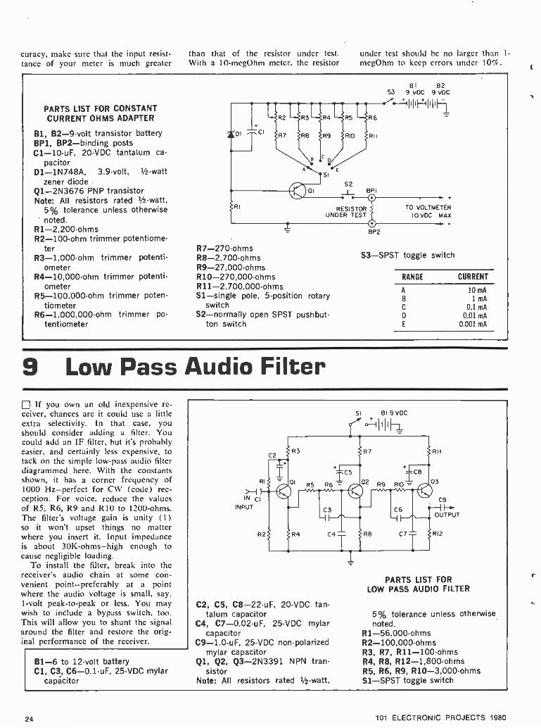
curacy, make sure that the input resist- than that of the resistor under test. under test should he no larger than 1-
megOhm to keep errors under 10'4. tance of your meter is much greater With a 10- megOhm meter. the resistor
PARTS LIST FOR CONSTANT CURRENT OHMS ADAPTER
B1, B2 -9 -volt transistor battery BP1, BP2- binding posts C1- 10 -uF, 20 -VDC tantalum ca-
pacitor D1- 1N748A, 3.9 -volt, 1/2 -watt
zener diode Q1- 2N3676 PNP transistor Note: All resistors rated 1/2 -watt,
5% tolerance unless otherwise noted.
R1- 2,200 -ohms R2- 100 -ohm trimmer potentiome-
ter R3- 1,000 -ohm trimmer potenti-
ometer R4- 10,000 -ohm trimmer potenti-
ometer R5- 100,000 -ohm trimmer poten-
tiometer R6- 1,000,000 -ohm trimmer po-
tentiometer
i O
RESISTOR UNDER TESTS
R7- 270 -ohms R8- 2,700 -ohms R9- 27.000 -ohms R10- 270,000 -ohms R11- 2,700,000 -ohms S1- single pole, 5- position rotary
switch S2- normally open SPST pushbut-
ton switch
BP2
TO VOLTMETER
10 VDC MAX
S3 -SPST toggle switch
RANGE
A
B
C
D
E
CURRENT
10 mA
1 mA
0.1 mA
0.01 mA
0.001 mA
9 Low Pass Audio Filter If you own an old inexpensive re-
ceiver, chances are it could use a little extra selectivity. In that case, you should consider adding a filter. You could add an IF filter, but it's probably easier, and certainly less expensive, to tack on the simple low -pass audio filter diagrammed here. With the constants shown, it has a corner frequency of 1000 Hz- perfect for CW (code) rec- ception. For voice. reduce the values of R5, R6, R9 and R 10 to 1200 -ohms. The filter's voltage gain is unity (1) so it won't upset things no matter where you insert it. Input impedance is about 30K -ohms -high enough to cause negligible loading.
To install the filter, break into the receiver's audio chain at some con- venient point -preferably at a point where the audio voltage is small, say, 1 -volt peak -to -peak or less. You may wish to include a bypass switch, too. This will allow you to shunt the signal around the filter and restore the orig- inal performance of the receiver.
B1 -6 to 12 -volt battery Cl, C3, C6- 0.1 -uF, 25 -VDC mylar
capacitor
C2, C5, C8- 22 -uF, 20 -VDC tan- talum capacitor
C4, C7- 0.02 -uF, 25 -VDC mylar capacitor
C9- 1.0 -uF, 25 -VDC non -polarized mylar capacitor
Q1, Q2, Q3- 2N3391 NPN tran- sistor
Note: All resistors rated 1/2 -watt,
PARTS LIST FOR LOW PASS AUDIO FILTER
5% tolerance unless otherwise noted.
R1- 56,000 -ohms R2- 100,000 -ohms R3, R7, R11- 100 -ohms R4, R8, R12- 1,800 -ohms R5, R6, R9, R10- 3,000 -ohms S1 -SPST toggle switch
P4 101 ELECTRONIC PROJECTS 1980

' 10 Portable Emergency Flasher For camping or highway emergen-
cies, here is a solid -state light flasher that's compact and reliable. QI, Q2 and the associated resistors and capa- citors comprise a conventional 2 -tran- sistor multivibrator. 02's emitter signal drives the Q3 -Q4 Darlington pair, which turns on high -current lamp Il. The light flashes on for about 0.4- second, then darkens for about the same period of time before turning on again. Power for the circuit comes from a standard 6 -volt lantern battery. You could probably build the entire flasher circuit inside the housing of your lan- tern, and actuate it only when neces- sary. If longer battery life is desired, and decreased illumination is accept- able, you could substitute a less power - hungry 6 -volt lamp for Il.
B1 -6 -volt lantern (heavy -duty) battery
Cl, C2- 1.0 -uF, 25 -VDC non -po- larized mylar capacitor
D1- 1N4002 diode
PARTS LIST FOR PORTABLE EMERGENCY FLASHER
I1 -#82 lamp rated 6.5 -VDC @
1 -amp Qi, Q2, Q3- 2N3904 NPN tran-
sistor Q4- 2N3724A NPN transistor
R1, R4-10,000-ohm, 1/2-watt re- sistor, 5%
R2, R3-390,000-ohm, 1/2-watt re- sistor, 5%
S1-SPST toggle switch
11 Equipment Theft Alarm As an electronics hobbyist, you very
likely own one or more pieces of ex- pensive equipment, and these can be very tempting targets for thieves or vandals. To protect your investment, why not install the simple alarm pic- tured here in some of your more valu- able possessions? Things like Amateur or CB transceivers, computers, oscil- loscopes and stereo equipment are all excellent candidates.
In the schematic, mercury switch SI is normally open. However, should the equipment in which the alarm has been installed be picked up and tilted, SI closes and thereby supplies gate cur- rent to the SCR. QI then latches in a
conducting state, causing current to
PARTS LIST FOR EQUIPMENT THEFT ALARM
B1 -6, 9, or 12 -volt battery BZ1 -6, 9, or 12 -volt buzzer D1- 1N4002 diode Q1- 2N5060 SCR R1, R2 -4,700 -ohm, 1/2 -watt re-
sistor S1- normally open SPST mercury
switch S2- normally closed pushbutton
switch S3 -SPST toggle switch
SI
flow through buzzer BZI. The buzzer will sound until pushbutton S2 is
pushed to reset the circuit. For best
results, use an electromechanical, rather than piezoelectronic buzzer, since it will emit more noise.
12 Vari -Rev Motor Control Old universal appliance motors
and shaded -pole induction motors salvaged from inexpensive turntables can be easily converted to slow -speed hobby drills, chemical stirrers. vari-
101 ELECTRONIC PROJECTS 1980
speed turntables, moveable display drives, etc. It's done with a full -wave Triac speed controller.
Unlike other speed controllers, which require an external trigger de-
vice, Ql combines both the Triac and Diac trigger diodes in the same case.
The motor used for the load must be limited to 6 amperes maximum (or 740 watts). Triac Ql must be
25

provided with a heat sink, which can be the metal cabinet. Build up a marblesize mound of epoxy on the cabinet and insert Q1's case into the epoxy. When the epoxy hardens the Triac's heat is dissipated to the cab- inet. Make certain Q1's case is not shorted to the cabinet and is insulated by the epoxy.
With the component values shown
PARTS LIST FOR VARI -REV MOTOR CONTROL
Cl, C2- 0.1 -uF, 200 -VDC capacitor al -RCA 40431 Triac -Diac R1- 100,000 -ohm linear taper
potentiometer R2- 10,000 -ohm, 1 -watt resistor
on the parts list, the Triac controls motor speed from full off to full on
13 Capacitance Oscillator If you own a triggered -sweep oscil-
loscope or a frequency counter capable of making period measurements, you can use this PUT (programmable uni- junction transistor) oscillator to mea- sure capacitance, The practical range of measurement extends from 100 -pF to about 10µF -wide enough to cover most of your measurement needs.
With an unknown capacitor con- nected across the binding posts, mea- sure the time interval between output pulses on your scope or frequency counter. To convert time to capaci- tance, use the relationship: CAPACITANCE (µF) = 10 x TIME For instance, a reading of 100- micro- seconds (.0001 -sec.) indicates a capac- itance of .001 -pF(or 100 -pF). (NOTE: 1 -µF = 1,000,000 -pF). To calibrate the oscillator, hook a 1000 -pF polystyrene capacitor across the binding posts, and adjust R1 until the time between out- put pulses is exactly 100 -microseconds.
PARTS LIST FOR
CAPACITANCE OSCILLATOR
B1 -9 -volt transistor battery BP1, BP2- binding posts C1- 100 -uF, 10 -VDC electrolytic
capacitor D1 -1N914 diode D2- 1N752A, 5.6 -volt, / -watt
zener diode Q1- 2N6027 programmable uni -
junction transistor - CAPACITOR UNDER TEST
L_
Note: All resistors rated 1/2-watt, 5% tolerance unless otherwise noted.
R1- 200,000 -ohm trimmer poten- tiometer
R2- 390,000 -ohms R3 -22 -ohms
R4- 1,000,000 -ohms R5, R6- 2,200 -ohms R7- 560 -ohms S1 -SPST toggle switch
14 Home Made NPO Capacitor From time to time, all of us encoun-
ter circuits that require large, non -po- larizert capacitors. Unfortunately, these are scarcer than the proverbial hen's teeth. Looking through some catalogs, you'll soon discover that capacitors larger than 10 -µf are usually electro- lytics, which are polarized devices. Electrolytic capacitors cannot be used in AC circuits, where the voltage under- goes periodic reversals in polarity. Such reversals destroy the insulating layer between the plates of an electrolytic capacitor, and the device soon fails.
So what can he done when you need a non -polarized capacitor for a hi -fi crossover or a motor -starting circuit, and all that you can find are electro- lytics? One alternative is to get some aluminum foil and roll your own, but there's an easier way. Just hook two
26
CI
`I(
DI
C2
)l'
1 D2
PARTS LIST FOR HOME MADE NPO CAPACITOR
Cl, C2- identical electrolytic ca- pacitors
D1, D2- identical silicon rectifiers
Note: Be sure to match voltage ratings of rectifiers and capaci- tors.
electrolytics back -to -back as we've diagrammed here, then add two cur- rent- steering diodes. These diodes en- sure that each capacitor sees only voltage of the correct polarity. CI and C2 should be identical, and each one should have a capacitance equal to the
value needed for proper circuit opera- tion. Make sure that the capacitors have working voltages equal to about three times the RMS value of the AC voltage in the circuit. Also, choose diodes having a PIV rating greater than or equal to the capacitor's rating.
101 ELECTRONIC PROJECTS 1980

15 Photoflood Dimmer #1 If you dabble in photography, you
know that in addition to natural light, there are two other light sources avail- able: flash or photoflood. Flash units are very popular because of their speed, which allows action to be captured, and their portability. However, it's ex- tremely difficult to visualize a shot with flash because the light appears only at the instant of exposure. High -intensity photofloods, on the other hand, are on continuously: therefore, the photogra- pher can readily compose a shot, pay- ing attention to details such as even- ness of illumination across the field and shadow placement.
As the photofloods burn, however, they generate a great deal of heat, which can be discomforting both to the photographer and the subject. In addition, it's wasteful of the photo-
PARTS LIST FOR PHOTOFLOOD DIMMER
D1- 1N5404 rectifier rated 400 PIV @ 3 -amps
I1 -EBV No. 2 500-watt photo- flood lamp
Sl- single pole, 3- position switch with contacts rated 10 -Amps @
120 VAC
li
flood lamp's already limited lifetime (about 8 hours for an EBV No. 2) to have it on any longer than absolutely necessary. You can use this simple dimmer to cut down the lamp's inten- sity during composition, thereby reduc- ing the heat generated and extending the lamp's useful life. With SI in its
middle position, power to the lamp is
cut in half because of rectifier Dl. When you're ready to expose, flip SI to full power. NOTE: On half- power, the lamp's color balance is shifted to- ward the red, so be careful not to make exposures at half -power with color film.
16 Square Wave Converter Got a yen to go digital but few
bucks to spend? Well, if you happen to have an old audio signal generator at hand, you can convert its sinewave out- put to a squarewave and save yourself the expense of a squarewave generator. The converter consists of an ordinary saturating transistor switch which, when driven by a large amplitude (about 10- VDC peak -to -peak or greater) sine - wave, yields squarewaves with reason- ably fast rise and fall times. Be certain to use as large an input amplitude as possible. Certain edge- triggered ICs,
PARTS LIST FOR SINE -TO-
SQUARE WAVE CONVERTER
C1- 1.0 -uF, 25 -VDC non -polarized mylar capacitor
Q1- 2N3904 NPN transistor R1- 4,700 -ohm, 1/2 -watt resistor,
5% R2- 1,000 -ohm, 1/2 -watt resistor,
5%
10V PT-P
1
SVDC
TUL flip -flops in particular, may fail to clock on a waveform whose rise and fall times are too long: however, the
majority of ICs will clock readily when driven by this converter.
17 The Brain Teaser Ordinarily, we tell you how the cir-
cuit works, but this time the tables are turned. Your job is to figure how to make LED I light by applying the cor- rect combination (or combinations) of input signals to points A and B. Sig- nals must be either +9 -VDC or 0 -VDC (gnd). Check your answer by bread- boarding the circuit: then, present this quiz to a friend. (HINT: You must consider four possible combinations.)
PARTS LIST FOR THE BRAIN TEASER
B1 -9 volt transistor battery
LED1 -light emitting diode rated 20mA @ 1.7 -VDC
Q1 thru Q6- 2N3904 NPN tran- sistor
R1- 330 -ohm, 1 /2-watt resistor. 5% R2 thru R7- 22,000 -ohm, 1/2 -watt
resistor, 5% Sl -SPST toggle switch
R4
101 ELECTRONIC PROJECTS 1980 27

18 EVM Timing Adapter If, like many other experimenters,
you own an electronic voltmeter - VTVM, FETVM or whatever -you might like to try this timely circuit. Connected to a high- impedance volt- meter set to read 10 -volts DC full - scale, the adapter permits the measure- ment of time intervals up to 100 -sec- onds long. Either analog or digital read- outs are acceptable, although. digital meters do have an edge as far as reso- lution is concerned. To convert voltage to time in seconds, just multiply by ten.
Referring to the schematic, it is ap- parent that when TIME button SI is pressed, constant -current source Q1 will begin to charge timing capacitor C 1. Since charging is being done by a
constant current, the voltage across C 1
rises linearly with time. Once SI is re- leased, the voltage on Cl remains "frozen" long enough for you to take
PARTS LIST FOR EVM TIMING ADAPTER
B1, B2 -9 -volt transistor battery C1- 10 -uF, 20 -VDC tantalum ca-
pacitor D1- 1N748A 3.9 -volt, 1/2-watt
zener diode D2-1N759A 12 -volt, 1/2-watt
zener diode Q1- 2N3906 PNP transistor R1- 2,700 -ohm, 1/2-watt resistor,
5% R2- 10,000 -ohm trimmer potenti-
ometer R3- 27,000 -ohm, 1/2-watt resistor,
5% R4- 100 -ohm, 1/2-watt resistor,
5%
S3 BI 9 VDC 82 9 VDC
R2
R3
-111111-111111
SI TIME
TO + ELECTRONIC
VOLTMETER CI 10-VOLT
SCALE
Si, S2- normally open button switch
S3 -SPST toggle switch
SPST push-
a reading. Press S2 to discharge C 1
before taking another measurement. Trimmer R2 can he adjusted so tha 10 -volts is reached in 100 seconds.
19 Phototachometer Adapter If you own a frequency counter, you
can use this nifty little circuit to mea- sure the rate of rotation of motors, fans and anything else that revolves and can break a beam of light. In the accompanying schematic, you can see that light from the bulb is chopped by the rotating fan blades. This chopped light beam then falls on the light - sensitive face of phototransistor Q 1.
Transistor Q2 amplifies the photo -cur- rent from Q1's emitter to yield a rectangular waveform approximately 9 -volt in amplitude at the output. Na- turally, the frequency of the output is related to the fan's speed of rotation.
RPM = Freq. (Hz) X 60
# of beam interruptions per second
PARTS LIST FOR PHOTOTACHOMETER ADAPTER
B1 -9 -volt transistor battery Q1 -FPT -100 phototransistor (or
equiv.) Q2- 2N3904 NPN transistor R1- 10,000 -ohm, 1/2-watt resistor,
5% S1 -SPST toggle switch
LIGHT SOURCE
+N C
01
TO FREQUENCY COUNTER
Suppose we obtain a frequncy reading of 100 Hz with the 3- bladed fan illus- trated here. Obviously, there are 3 in- terruptions per revolution. The actual speed is therefore 2000 RPM. For best results, mount Q1 in a small, hollow
tube (an old pen barrel, for example) with its light- sensitive face recessed with respect to one end. This will en- sure that only the chopped beam strikes the phototransistor.
20 Low -Power Dummy Load For transmitter tune -up and testing,
you need some sort of dummy load. As far as your transmitter is concerned, the dummy load looks just like a nor- mal 50 -ohm antenna. However, with a dummy load, almost all of the trans- mitter's output power is dissipated as heat rather than being radiated as RF. This makes little difference to the trans- mitter itself, but it makes a world of
difference to nearby Amateurs or CB- ers because they don't have to contend with the interference generated as you fiddle with your transmitter.
Dummy loads are available commer- cially, but the Amateur QRP (low - power) enthusiast or CB'er can easily and inexpensively build his own. All you need are four 50 -ohm, 2 -watt, car- bon- composition resistors, a coax plug
and a minibox. (You must not use wire - wound resistors, even though they are capable of handling more power than carbon resistors, because wirewounds exhibit too much inductance.) Keep the interconnecting wires as short as pos- sible to minimize stray inductance and capacitance. Used on an intermittent basis, this dummy can safely handle about 15- watts.
28 101 ELECTRONIC PROJECTS 1980
4

PARTS LIST FOR LOW -POWER DUMMY LOAD
RI R3 PI
P1 -PL -259 coaxial plug R1 thru R4 -5 -ohm, 2 -watt carbon
composition resistors R2 R4
21 The Light Latch Looking for a novel way to control
electrical apparatus or appliances? Here's a bright idea: Why not use a
beam of light? This little light latch can he readily actuated by a flashlight beam and is capable of controlling as
much current as your relay's contacts will allow (1 to 3 -Amps, typically). When phototransistor QI is momen- tarily illuminated, relay K 1 is latched in its closed position and your appliance is ON. To turn your load OFF, shine a beam of light briefly on 02's light - sensitive face. Feedback between Q3 and Q4 via R3 and R4 is responsible for the latching action. Be sure to mount phototransistors QI and Q2 so
that room light does not fall on them. Recessing the phototransistors within small -diameter pieces of tubing is a
good way to exclude extraneous light.
RI
SI BI9VDC
PARTS LIST FOR LIGHT LATCH
B1 -6 or 9 -volt battery D1, D2 -1N914 diode K1 -relay with 6 -volt coil rated @
500 -ohms, with SPST contacts Q1, Q2 -FPT -100 phototransistor
Q3, Q4, Q5-2N3904 NPN tran- sistor
R1, R2-10,000-ohm, 1/2-watt re-
sistor, 5% R3, R4-100.000-ohm, 1/2-watt re-
sistor, 5% Sl-SPST toggle switch
22 Battery Monitor T1 Tired of playing guessing games with your batteries? With this battery - voltage monitor you'll know at a glance whether or not batteries need replace- ment. The circuit's compact size, which comes about because it's a meterless voltage monitor, makes it easy to build into an existing piece of equipment. To use the device, press SI and, if LEDI lights up, your batteries are still good. If not. throw them away.
Transistor QI's gain makes the mon- itor very sensitive to changes in voltage. Consequently, LED 1 is either ON or OFF with little ambiguity most of the time. The voltage level being sensed is determined by zener diode Dl's rat- ing and the base- emitter voltage drop of Q1. Specifically, the switching point is equal to the zener voltage plus 0.75-
PARTS LIST FOR BATTERY MONITOR
D1 -zener diode (see text) LED1 -light emitting diode rated
20 -mA @ 1.7VDC Q1- 2N3904 NPN transistor R1 -1,500 -ohm, 1/2-watt resistor,
5% R2- 680 -ohm, 1/ -watt resistor,
5% S1- normally open SPST push-
button switch
+5 TO +18V >--~SI
volts. For example, a 5.6 -volt zener diode will set the trip level at approx- imately 6.35- volts. The voltage level you choose should be less than the bat- tery's nominal voltage when fresh. A 9 -volt battery, for example, might be
useless when its voltage drops to 7.5- volts; however, the exact point at which a battery becomes useless depends both on the battery and on the application. Finally, it's best to test the battery with a normal load current being drawn
23 Simple Pulse Circuits Need a source of pulses for your
digital experimenting? If you already own a squarewave generator, here's a
cheap and easy way to convert its out-
101 ELECTRONIC PROJECTS 1980
put to pulses. All you need are an R/C differentiating network and a rectifier diode. Circuit A gives you positive out- put pulses, while oircuit B furnishes
negative pulses. Pulse duration, mea- sured at a voltage level about one -third of peak value, is one -microsecond in both cases. If you want longer pulse
29

durations, simply increase the value of Cl or C2. When driven by a low -im- pedance squarewave generator, both
circuits are capable of clocking CMOS or TTL. The amplitude of the square - wave input should he about equal to
the supply voltage of the circuit being driven -5 -volts for TTL, 5 to 15 -volts for CMOS.
PARTS LIST FOR SIMPLE PULSE CIRCUITS
C1- 0.003 -uF, 35 -VDC polystyrene capacitor
C2- 0.001 -uF, 35 -VDC polystyrene capacitor
D1, D2 -1N914 diode R1- 330 -ohm, lh -watt resistor,
5% R2- 1,000 -ohm, 1/2 -watt resistor,
5%
A A B B
24 Solar- Powered Metronome You'll never miss a beat because of
dead batteries with this metronome. As long as there is a little sunlight or lamp- light to illuminate the silicon solar cells, the circuit will keep ticking away
merrily. The six series- connected solar cells provide a supply potential of 3- volts for the PUT relaxation oscillator. Potentiometer RI can he adjusted to yield the desired pulse rate. Should you
wish to lower the output volume, a
small resistor on the order of 10 -ohms may be installed in series with the speaker.
PARTS SOLAR -POWER
C1- 220 -uF, 25 -VDC electrolytic capacitor
C2- 0.39 -uF, 25 -VDC mylar ca- pacitor
PV1 thru PV6 -0.5 -VDC silicon solar cells (Radio Shack #276- 120 or equiv.)
Q1- 2N6027 programmable uni- junction transistor
LIST FOR ED METRONOME
R1- 2,000,000 -ohm linear -taper potentiometer
R2- 470,000 -ohm, 1/2 -watt re- sistor, 5%
R3- 1,500,000 -ohm, 1/2 -watt re- sistor, 5%
R4- 2,400,000 -ohm, 1/2 -watt re- sistor, 5%
SPKR -8 -ohm PM miniature speaker
R3
R4
25 Record Restorer Old 78 -rpm collector's -item rec-
ords cut back in the early days when performers sang in front of a large horn usually have a peak in the mid - band that drives the sound into your mind like a fingernail scratched across a blackboard. The overall sound quality is easily tamed, and made more natural and modern, by attenuating the shrill peaks with a
Record Restorer, a device that sup- presses, by hi -fi standards, the mid - band frequencies.
The Record Restorer should be as- sembled in a metal cabinet to prevent hum pickup. Connect the output of
30
PARTS LIST FOR RECORD RESTORER
RI 270K V'Sh
CI 0.2uF
C2 02uF
C3 0.2uF
Cl, C3- 0.25 -uF mylar capacitor C2- 0.02 -uF mylar capacitor R1- 270,000 -ohm, V2 -watt resistor R2, R3- 50,000 -ohm potentiometer,
linear taper
tN( Lr uT R2 SOK
r 1
your phonograph to the restorer in- put. Connect the output of the re- storer to your tape recorder. Set po- tentiometer R2 to maximum resist- ance and adjust potentiometer R3 for
the most pleasing sound. If R3's ad- justment is too little, or too much as
evidenced by a "hole" in the sound quality, trim the restorer with R2 un- til you get the optimum equalization.
101 ELECTRONIC PROJECTS 1980

26 Three -Dial Combination Lock Here's an effective little combination
lock that you can put together in one evening's time. To open the lock, simply dial in the correct combination on the three rotary or thumbwheel switches. With the correct combination entered, curent flows through R I into
QI's gate terminal, causing the SCR to latch in a conductive state. This sends a current through relay K 1,
which responds by closing its contacts and actuating whatever load is at- tached. After opening the lock, twirl the dials of SI through S3 away from
the correct combination so that nobody gets a look at it. The lock will remain open and your load will remain on because the SCR is latched on. To lock things up, it's only necessary to inter- rupt the flow of anode current through the SCR by pressing pushbutton S4.
PARTS LIST FOR THREE -DIAL COMBINATION LOCK
C1- 500 -uF, 25 -VDC electrolytic capacitor
D1, D2- 1N4002 diode K1 -relay with 6 -volt coil rated @
250 -ohms, with SPST contacts Q1- 2N5050 SCR R1, R2- 4,700 -ohm, 1/2-watt resis-
tor, 5% Si, S2, S3- single pole, 10 -posi-
tion rotary or thumbwheel switches
S4- normally closed SPST push- button switch
T1- 120 -VAC to 6.3 -VAC @ 300mA power transformer
RI 02
DI S2 . S3
A
27 Microcomputer /AC Interface Here's one of the simplest and best
ways to harness your microcomputer for the purpose of appliance control. Let an output line drive relay K1, a small, 5 -volt device designed expressly for TTL. The relay's contacts supply gate drive to Triac Q1 which, in turn, does the hard job of controlling the relatively large load current. Besides controlling the Triac, relay K1 also isolates the logic circuitry from the AC line. Cl and R2 prevent false turn on of the Triac with inductive loads, and FI protects the Triac should the load short out. Of course, this circuit can be used to interface any type of logic circuit -not just a microcomputer -to the AC line.
PARTS LIST FOR MICROCOMPUTER /AC
INTERFACE
C1- 0.1 -uF, 50 -VDC ceramic ca- pacitor
D1- 1N4002 diode F1 -3AG 10 -amp fuse (fast- acting
type only) K1 -relay with coil rated 5 -VDC @
50 -ohms, with SPST contacts (use 1/2 of Radio Shack part #275-215). Note: For very high speed switching applications, use a reed relay with similar specifications.
Q1 -Triac rated 200 -volts @ 10-
Amps (Motorola part #MAC11- 4, Sylvania part #ECG5624)
R1- 1,000 -ohm, 1 -watt, 5% re-
sistor R2 -10 -ohm, 1 -watt, 5% resistor
28 Hi Temp Alarm Has a temperature -control problem
got you hot under the collar? Well, this little temperature alarm /thermostat may be just the thing to cool you down. Temperature -sensing is done by ther- mistor RR5, a negative -temperature-
101 ELECTRONIC PROJECTS 1980
coefficient device whose resistance varies between 10K -ohms at 77° F, and about 1000 -ohms at 200° F. Po- tentiometer R I sets the exact tempera- ture at which the Q1 -Q2 Darlington pair gets turned on by the thermistor's
signal. Whenever ambient temperature rises above the alarm setting, the tran- sistors conduct current through the buzzer, which then emits an attention - getting shriek.
Note that the thermistor must be
31

located away from the control circuitry -as indicated by the dashed line in the schematic -so that the operation of the
control circuit is not adv&rsely affected by temperature extremes. If a 6 -volt, 500 -ohm relay is suhstited for the buz-
zer, you get a thermostat capable of turning on a fan or turning off a small electric heater.
PARTS LIST FOR HI -TEMP ALARM
B1 -9 -volt transistor battery BZ1 -9 -VDC buzzer (Radio Shack
#273-052) C1- 220 -uF, 10 -VDC electrolytic
capacitor D1- 1N752A, 5.6 -volt, 1/2 -watt
zener diode Q1, Q2- 2N3904 NPN transistor R1- 2,000 -ohm trimmer potenti-
ometer R2, R3 -1,000 -ohm. 1/2 -watt, 5%
resistor R4- 820 -ohm, 1/2-watt, 5% re-
sistor R5- thermistor rated 10.000 -ohms
@ 25 °C (Fenwal part *RB41L1) S1 -SPST toggle switch
R5
R4
SI BI9VDC
4IIII1-1
RANGE =80 °F ITO 200°F
DI
29 Simple Touch Switch Looking for a way to add a touch
of class to your digital projects? Try this touch switch. Not only does it add a note of distinction to a project, but it's bounce -free as well. Whenever a finger touches the contact plate, stray 60 Hz powerline interference is coupled into the circuit due to the antenna ef- fect of your body. The 60 Hz pickup is rectified and filtered to provide a negative bias on Ql's gate, thus caus- ing Q I to turn off and Q2 to turn on. As a result, Q2's collector drops to ground potential. When the touch plate is released, the potential at Q2's col- lector terminal once again jumps high. You can use the output to drive either CMOS or TTL with ease.
Note that if you do your experiment- ing in a place devoid of 60 Hz power - line radiation -in the middle of a field
PARTS LIST FOR SIMPLE TOUCH SWITCH
C1- 0.1 -uF, 50 -VDC ceramic ca- pacitor
D1, D2 -1N914 diode Q1- 2N5953 n- channel JFET
(junction field effect transistor) Q2- 2N3904 NPN transistor Note: All resistors rated 1/2 -watt,
5% tolerance unless otherwise noted.
R1- 100,000 -ohms R2- 22,000,000 -ohms R3- 27,000 -ohms R4- 1,000 -ohms
TOUCH PROBE
RI D2 ol
.5VDC
R4
OUTPUT
02
/4, OPTIONAL EARTH GND
TP- copper or aluminum touch plate
of wheat, for example -the circuit will not work. The average home is full of 60 Hz radiation, however, so the switch should function well. If you have some
difficulty, connect your system's elec- trical ground to an earth ground (the screw on your AC outlet's cover plate). This will boost the signal pickup.
30 Cigar Lighter Power When you want to run your radio
or some other low -power 9 volt de- vice in your car, here's a way you can do it and save on batteries. This is a
simple shunt regulator using a 2N- 2222 and 9.1 Volt Zencr. With a 2N2222, you can power devices re- quiring as much as 800 ma; to drive devices requiring more current, use a
PARTS LIST FOR CIGAR LIGHTER POWER
C1- 100 -uF capacitor D1 -Zener diode, 9.1 V at 1/4 -watt Q1 -NPN transistor, 2N2222 or
equiv. R1- 560 -ohm resistor, 1/2 -watt
s o s ll +II -16 FROM CAR REGULATED 9
VOLTS OUT
DI
32 101 ELECTRONIC PROJECTS 1980

2N3G55. With either device, unless the equipment you are driving is very low power, use a heat sink.
There are two easy ways to deter- mine how much current your transis- tor radio or whatever draws (more to the point, whether or not the amount
of current it draws will necessitate heat sinking). One is to connect your VOM in series between one of the battery posts and its associated clip connector. You will want to check the maximum amount of current drawn. Another way is to connect
this circuit for only a few seconds and touch Q1 with your finger. If it gets too hot to hold your finger on, use a heat sink. You may want to use a heat sink in any case. You may also want to include a small fuse (try 1/2
amp).
31 Tom Thumb's Timer rJ We're found a timer circuit that little Tom would have approved of- it's snail both in size and in cost. With SI in contact with +9VDC, capacitor Cl gradually charges through RI and R2. When the potential across Cl reaches 5.5- volts, base drive flows into the QI -Q2 Darlington pair through zener diode D2. This causes the transis- tors ?o conduct collector current and activate buzzer BZI, a miniature device that emits a pleasant, shrill tone to sig- nal the end of the timed interval. To reset the timer. flip Si so that it con- tacts R3, which functions to discharge timing capacitor CI through diode D I.
Using trimmer R1, you can adjust the timed interval to any value between 30 and 120- seconds. We use this timer to coitrol the development of Polaroid instant films, but you can probably find dozers of other uses, too.
PARTS LIST FOR TOM THUMB'S TIMER
B1 -9 -volt transistor battery BZ1 -9 -VDC buzzer (Radio Shack
# 273.052) C1- 470u F, 25VDC electrolytic
capacitor D1- 1N4002 diode D2 -1 N748A, 3.9-volt, 1/2watt
zener diode Q1, Q2- 2N3904 NPN transistor R1- 200,000 -ohm trimmer poten-
tiometer R2-62,000-ohm, 1/2 -watt, 5% re-
sistor R3- 330 -ohm, 1/2-watt, 5% re-
sistor S1 -SPDT slide switch
SI
+ 5vDC
32 Bounce -less Digital Switch (l When it comes to feeding informa- tion :o a digital circuit, the simplest way :o accomplish the job is with a switch of some sort. Unfortunately, except for the mercury switch, every other commonly available switch bounces like a bad check. When you press a "bouncy" switch expecting just one closure, you get surprised with a
multitude instead. Since the reaction time of digital logic is so swift, each bounce is treated as a separate input - often with disastrous results.
Consequently, it's usually necessary to de- bounce switches in logic circuits. The circuit diagrammed here is a
simple and effective way to do the job. Press SI, and about 30- milliseconds later you get one and only one pulse at Ql's output. This bounce eliminator is well suited for incorporation into any TTL circuit.
101 ELECTRONIC PROJECTS 1980
PARTS LIST FOR
BOUNCE -LESS DIGITAL SWITCH
C1- 2.2 -uF, 10 -VDC tantalum ca- pacitor
Q1- 2N6027 programmable uni- junction transistor
Note: All resistors rated 1/2-watt, 5% tolerance unless otherwise noted.
R1- 10,000 -ohms R2-47 -ohms R3- 390,000 -ohms R4- 1,200,000 -ohms S1- normally open SPST pushbut-
ton switch
RI
R2
33

CIE has a terrific idea
for a few people who know what
they want.

If you want success in electronics ... if you want the skills people are glad to pay for ... find out about CIE training.
It's a terrific idea that can get you on your way to success in electronics troubleshooting.
I.et's face it. learning valuable new skills isn't something you just breeze through. Especially in a modern technological field like electronics troubleshooting. you've got to really want success if) ou're going to build your skills properly.
But. oh hoy. the rewards when you do! In today's world. the ones Who really know electronics troubleshooting find that people ... even industries ... look tin' their help.
What about you? How much do you want the thrill ol'success ... of being in demand? Enough to roll up your sleeves and work for it?
Why it pays to build troubleshooting skills.
Suppose the automated production controls on an assembly line break down. Imagine how much money the manufacturer can lose when help doesn't comc%n.ct! And it takes a
skilled electronics troubleshooter to move in ... locate the problem ... solve it ... and get the lines moving again.
Or take a TV station. Breakdowns are costly in broadcasting where time is money. Viewers won't sit forever waiting for sound or the picture to come hack. Before they change channels. the station needs to get hack on the air again - with the help of a skilled troubleshooter.
No question about it. Building new skills in electronics troubleshooting is an investment in your future. It's well worth the effort.
Why you should get CIE to help you do it .
roubleshooting starts with ideas ... principles. CIE's Auto -Programmed" Lessons help you get the idea -at your on most comfortable pace. Step by step at home. you explore each principle -each theory - until you understand it thoroughly and completely. Then you start to use it.
How CIE helps you turn ideas into reality .
If you're a beginner, you start with CIE's Personal Training Laboratory. You actually perform over 200 experiments to help you grasp the basics. Plus you use a 3 -in -1 Precision Multimeter to get your first taste of the testing, checking. analyzing steps you take in troubleshooting!
How 3 practical steps help you build troubleshooting skills .
You'll take your first practical step in professional troubleshooting when you build our own 5 M Ht triggered -sweep. solid -state oscilloscope.
As a trained troubleshooter. you'll use your oscilloscope the way a doctor uses his X -ray machine. As a student. you learn how to "read" w avefrm patterns on a big. 8cm. s I (f cm. screen ... how to "lock them in" for closer study ... how to understand and interpret what they tell you.
Your second practical. skill -building step begins when you get your Zenith
9 -inch diagonal. solid -state color TV - featuring nine removable modules! Now's your chance to apply the new skills you learned with your oscilloscope!
With CIE's guidance. you perform actual service operations -the kind you'd handle on the job as a trained troubleshooter! Using the TV. you learn to trace signal flow ... detect and locate malfunctions... restore perfect operating standards ... just as you would with any sophisticated electronics equipment.
Finally. step three rounds out your experience as you work with a
completely solid -state color har generator - actually a TV signal transmitter that produces ten different display patterns on your TV screen!
You study a gated color bar rainbow ... crosshatch lines ...dot patterns.
You explore digital logic circuits ... observe the action of a crystal - controlled oscillator!
This practical. "hands on" training takes concentration and effort. But it's enjoyable and rewarding. And it's a
great way to prepare for a
troubleshooting career!
Why it's important to get your FCC License .
For some troubleshooting jobs. you Hoist have your FCC License. For others. employers often consider it a
mark in your favor. It's government - certified proof of specific knowledge and skills!
Almost 4 out of 5 CIE graduates who take the exam get their Licenses. More than half of CIE's courses can prepare Not' for it ... and the broadest range of career opportunities!
Free catalog! \tail the card. If it'S gone. cut out and
mail the coupon. If you prefer to write. mention the name of this magazine. We'll send you a copy of CIE's FREE school catalog -plus a complete package of independent home study information! For your convenience. we'll try to have a representative call to help you with course selection. Mail the card or coupon ... or write: CIE. 17Th East 17th Street. Cleveland. Ohio 44114.
111 MN NM If= I. 1 ECleveland Institute of Electronics, Inc. ,CI
1 ,
1
1776 East. 17Gn Str-eat. ev11a.d. Onn 44114 Acc.eanea M.mEa National Nome Sway Council
Y ES . . . I ,,ant to succeed in cleownics. Send nie nt) I It I I (II school c :u:dug - including detail. :thorn u'ouhleshaoi ng cuures - plu. ms I- K I t package of hume study information' EN 23
NAME Iptea,eprint)
ADDRESS APT.
c rry
STATE ZIP
IAGE PHONE (area code) ' ( heck ho. Ga t I I (till ndurmauon: 'cicran \.tnc Duty
Mail today! 0E-16

33 Multivibrator Tone Hummer This multivibrator produces an
audio tone rich in harmonics. If you were to look at the output on an oscilloscope, you would see it is a square wave. Because it is so rich in harmonics, you can use this circuit as a signal injector for tracing signals in audio, if (intermediate frequency),
and even some rf stages. Just how high the harmonics will go depends on the particular transistors you choose, the voltage you operate them at, and the specific values of the other components.
You can also use this circuit to pro- vide very fast clock pulses to logic
circuits, with pulse width in the frac- tion-of-a- millisecond range, if you like. Remember, the higher in pitch the tone that you hear, the shorter each pulse width. You can also use this as a signal injector or signal source in setting up stereo or inter- com systems.
PARTS LIST FOR MULTIVIBRATOR TONE HUMMER
B1-6-15 VDC Cl, C2-.05-.5-uF capacitors R1, R4-2200-4700-ohm resistors.
1/2 -watt. R2, R3-4700-100,000-ohm resis-
tors, 1/2-watt S1-SPST switch Q1, Q2-NPN transistor (2N2222,
2N3904 or equiv.)
+
BI
/77
SI
_
o
RI
0
R2
b
R3
C2
02 c
R4
b o
CI
34 Basic Color Organ This simple color organ is certain
to keep your party from becoming a drag. Connected to your hi -fi ampli- fier's speaker output (across the speaker terminals) it will throb in time to the music. Paint the bulb red or deep blue and your party room will take on the atmosphere of a rock club.
Transformer TI can be any match- ing transistor type in the range of 500 '500 to 2500 /2500 ohms. Note that none of the connections from SCR1 or its components are connect- ed to ground. For safety's sake, you must keep the 117 -volt line voltage from the amplifier connections- that's the reason for Tl. To adjust, set po-
tentiometer R 1 "off" and adjust the amplifier volume control for a normal listening level. Then adjust RI until lamp I1 starts to throb in step with the beat.
AUDIO INPUT 500
TI
PARTS LIST FOR BASIC COLOR ORGAN
I1 -117V lamp, not to exceed 40 watts.
R1- Potentiometer, 500 to 5000 ohms
SCR1- Silicon Controlled Rectifier, HEP R1218
T1- Transistor output transformer, see text
SCRs
LAMP
117 VAC
35 Nine Volt Neon Wait a minute! Don't neon lamps
need ninety volts to fire? Neon lamp I1 gets that kind of voltage -possibly more, depending on the state of your battery and the actual value of T1. Because T1 and 01 act together to form a DC -to -AC converter.
38
RI and CI set the frequency of UJT oscillator Q1 to about 1000 Hertz. Actually, any frequency near the middle of the audio range (300- 5,000 Hz) would be okay, so feel free to take some liberties with R1 and Cl's values. That's because those
are the frequencies that are easiest to handle for TI, a transistor -type inter - stage transformer. You may find something suitable in one of your old junker radios or amplifier boards.
Tl acts as a step -up transformer, raising the input voltage to a level
101 ELECTRONIC PROJECTS 1980
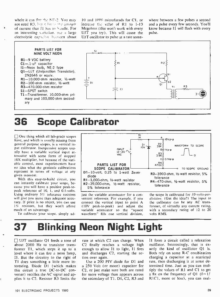
where it can fire the NT' -2 You may not need R3, ',! :t it !in:': amount
b of current that I I has to h- ladle. For an interesting a:Iriation. u: e a large electrolytic c.! I cen about
10 and 1000 microfarads for Cl, or increase trio value of R1 to 1 -19 Megohms (this won't work with every UJT you try). This will zause the UJT oscillator to pulse at a rate some-
where between a few pulses a second and a pulse every few seconds. You'll know because I1 will flash with every pulse.
PARTS LIST FOR NINE VOLT NEON
B1 -9 VDC battery C1 -.1 -uF capacitor I1 -Neon bulb, NE -2 type Q1 -UJT (Unijunction Transistor),
2N2646 or equiv. R1- 10,000 -ohm resistor, 1/2-watt R2- 100 -ohm resistor, 1/2-watt R3- 470,000 -ohm resistor Sl-SPST switch T1- Transformer, 10,000 -ohm pri-
m,ry and 100,000 -ohm second- a ry
Si
BI
b
b2
Ti
RI R2
Ash
CI R3
MID
36 Scope Calibrator Li One thing which all lab -grade scopes have, and which is usually missing from general purpose scopes, is a vertical in- put calibrator. Inexpensive scopes usu- ally have a variable vertical input at- tenuator with some form of stepped 10X multiplier, but because of the vari- able control, most experimenters have no idea what the graticule calibrations represent in terms of voltage at any given moment.
With this easy -to -build circuit, you can instantly calibrate your scope, be- cause you will have a positive peak -to- peak reference of 10, 1, and 0.1- volts. Using ordinary 5';S tolerance resistors will give you more than adequate accu- racy. If price is no object, you can use 1% resistors, but they won't afford much of an advantage.
To calibrate your scope. simply ad-
RI 1K
INPUT o
12 -20 r1., VAC
PARTS LIST FOR SCOPE CALIBRATOR
D1 -10 -volt, 0.25 to 1 -watt Zener diode
R1- 1,000 -ohm, 1/ -watt resistor R2- 39,000 -ohm, 1/2-watt resistor,
5% tolerance
DI 10V 39K
B. IVp-p R3
3.9K C 0.1Vp-p
IOVp-p
R4 4700
WAVEFORM TO SCOPE
0
o TO SCOPE GROUND
R3- 3900 -ohm, 1/2-watt resistor, 5% tolerance
R4- 470 -ohm, ' 2 -watt resistor, 5% tolerance
just the variable attentuator for a con- venient reference. For example, if you connect the vertical input to point A (10V peak -to -peak) and adjust the variable attenuator so the "square waveform" fills one vertical division,
the scope is calibrated for 10-volts-per- division. (Get the idea ?) The input to the calibrator can be any AC trans- former, of virtually any current rating, with a secondary rating of 12 to 20 volts RMS.
37 Blinking Neon Night Light ¡ UJT oscillator Q1 feeds a tone of
about 2000 Hz to transistor trans- former TI, which steps it up to a level where it can fire a neon lamp, Il. But the circuitry to the right of T1 does something a little more in- teresting. Diode D1 (which makes this circuit a true DC -to -DC con- verter) rectifies the AC signal and ap- plies it to C2. Resistor R3 limits the
101 ELECTRONIC PROJECTS 1980
rate at which C2 can charge. When C2 finally reaches a voltage high enough to allow 11 to light, I1 fires and discharges C2, starting the ac- tion over again.
Use a 200 PIV diode for D1 and a 250 Volt (or more) capacitor for C2, or just make sure both are rated for more voltage than appears across the secondary of T 1. D1, C2, R3 and
I1 form a circuit called a relaxation oscillator. Interestingly, that is ex- actly the kind of oscillator Q1 is. Both rely on some R -C combination charging a capacitor at a restricted rate, then discharging it at some de- termined time. Just as you can mul- tiply the values of R1 and Cl to get a fix on the frequency of 01 (f =11 RIC1, more or less), you can mul-
39

RI
cI
T
PARTS LIST FOR
BLINKING NEON NIGHT LIGHT
B1 -9 VDC battery R1- 10,000 -ohm resistor. 1/2 -watt C1- .05 -uF capacitor R2- 100 -ohm resistor C2 -.5 -uF electrolytic capacitor, R3- 470.000 -ohm resistor, 1/2-
450 VDC watt Dl-Diode, 1N4001 or equiv. S1 -SPST switch Ql-UJT (Unijunction Transistor), T1- Transformer, 10,000 -ohm pri-
2N2646 or equiv. mary and 100,000 -ohm second- ary
DI tiply R3 and C2 to determine that the NE -2 will blink about four times a second. You can also connect the circuit to the right of Tl to 110 Volt household power to see the same talon.
38 Lo Hum Power Supply Just a handful of components art_
needed for a line- powered low- voltage low- current supply for powering audio preamplifiers.
The values for different voltage and current outputs are given in the Parts List. Pick the set you need and wire up. DI and D2 are silicon rec- tifiers rated at a minimum of 200 PIV at any current.
Out- put V
12 12 25
117 VAC J
Ri D1
I D2 c1
PARTS LIST FOR LO HUM POWER SUPPLY
R2 +ODC
OUTPUT
I max* R1 Cl R2
1 mA 43,000 -ohm, 1/2 -watt 250 -uF, 15 -VDC 180,000 -ohm, 1/2 -watt 2 mA 22,000 -ohm, 1/2 -watt 250 -uF, 15 -VDC 100,000 -ohm, 1/2 -watt 2 mA 18,000 -ohm, 1/2 -watt 250 -uF, 30 -VDC 180,000 -ohm, 1/2-watt
*For lower current, decrease value of R2
39 Scratch Filter Next time you're dubbing some "old-
ies but goodies" to tape, there's no need to put up with the scratches and noise that have accumulated over a good number of years of usage. Just pass the signals from the records through this scratch filter, and you'll get rid of much of the noise without too much loss of music frequencies.
The filter connects between the signal source, such as a record player or an amplifier's tape output, and the line input of a tape recorder. it's cut -off frequency is slightly higher than 5000 Hz, with attenuation increasing as the frequency goes up. Potentiometer R2
FROM SIGNAL SOURCE
PARTS LIST FOR SCRATCH FILTER Cl, C2- 260 -pF silver mica capaci-
tor, 5% or better tolerance R1- 100,000 -ohm, 1/2 -watt resistor
TO RECORDER
R2- 100,000 -ohm, linear taper po- tentiometer
R3- 47,000 -ohm, 1/2-watt resistor
permits you to vary the "corner" fre- quency slightly to attain more or less
high frequency attenuation as required by the individual record. (Or, you can
just set the control to the approximate center and forget about it) For proper operation, the input impedance of the recorder should not he less than 40.000
40 101 ELECTRONIC PROJECTS 1980

ohms -a common minimum value for most recorders. Do not eliminate R3 in an attempt to increase the output level
of the filter, because it provides part of the filter's output impedance match- ing in conjunction with the recorder's
input impedance. A metal enclosure is suggested. with RCA -type phono jack connectors.
40 Noise Generator PARTS LIST FOR
NOISE GENERATOR
B1 -9 VDC battery C1- .05 -uF capacitor C2- 220 -uF capacitor C3- .005 -uF capacitor R1- 1- Megohm resistor, 1/2-watt R2 -1.8- Megohm resistor, 1/2-watt R3, R5- 150 -ohm resistor, t/2 -watt R4- 120,000 -ohm resistor, th -watt R6- 56,000 -ohm resistor, 1/2-watt Q1, Q2 -NPN transistor, 2N3904
or equiv. S1 -SPST switch
Audio buffs often refer to their systems as having color or tempera- ture. One that is rich in low end response is said to be warm and red; a bright high end on a system means it's cool and blue.
The mixture of all these character- istic colors is white, and white noise generators produce a whooshing
shound that is randomly distributed throughout the spectrum. Likewise, pink noise generators are just a bit warmer. This simple noise generator is one we might call off -white. It takes advantage of the junction noise generated in a reverse -biased semi- conductor junction (here, a base -to- emitter junction in NPN transistor
Q ). The noise generated by current
through Q1 is amplified by Q2 and made available at the output. For a
simple demonstration of tonal color- ing, patch this noise into your sound system and see how manipulating your tone controls alters the nature of the noise your hear.
41 Budget Lamp Dimmer Using almost all "junk box" parts,
or those easily found at local parts dis- tributors, this budget- priced lamp dim- mer can be assembled directly inside a
lamp socket, lamp base, or electrical outlet box (replacing a wall switch).
Triac Ql can handle up to 75 -watts without a heat sink. Over 75 watts, sink Q I to the metal enclosure, or a small heat sink insulated from the socket (if
you build the dimmer into a socket). If you mount Ql on the enclosure, make certain none of the Triac's leads "short" to the enclosure. Use silicon heat sink grease between Q1 and the sink.
I1 is an ordinary NE -2 neon lamp. If it will somehow be exposed to light, paint the lamp black, or some other opaque color. (I1's "trigger" voltage
threshold is affected by light.) Because the neon lamp has a firing
threshold above zero volts, the lamp cannot be turned fully off with the con- trol. Rather, switch Si snaps the lamp on to a very subdued brilliance which can be faded up to almost maximum lamp brilliance. Make certain RI is wired so it is a maximum resistance just before SI switches from on to off.
PARTS LIST FOR BUDGET LAMP DIMMER I2 _ __
Cl, C3- 0.02 -uF, 50 -VDC ceramic RI
disc capacitor 50K SI
C2, C4- 0.05 -uF, 50 -VDC ceramic 01
disc capacitor R1723
I1 -NE -2 neon lamp I2 -75 -watt or smaller standard R2 II NE-2
lighting fixture 15K .,-.
Q1- HEP -R1723 Triac C4 PAINT ,íM120 VAC
R1- 50,000 -ohm, linear taper po-CI -I- C2- C31. tentiometer T
05 BLACK
R2- 15,000 -ohm, 1/2-watt resistor
101 ELECTRONIC PROJECTS 1980 41

42 High Performance Transistor Radio U Here's a neat way to update your crystal set, assuming you can still find it. Or use these few inexpensive parts to build from scratch. Instead of using a cat's whisker or a diode, this radio uses the very sensitive junction of a junction FET as its detector. This makes it a very "hot," very sen- sitive high impedance detector. Then the JFET does double duty by con-
verting the high input impedance to a lower output impedance -low enough and with enough drive to power a set of high impedance headphones or a high impedance earphone (about 1K or so).
The antenna coil is one of those simple loopsticks you've seen at the parts stores. (Or you might want to wind your own on an oatmeal box.)
The broadcast variable capacitor is
one of the tuning capacitors taken from an old, defunct radio. You can use any long wire for the antenna, but if you string it outdoors, be sure to use a lightning arrestor. You can also clip an alligator clip to your bed- spring, a windowscreen, or the metal part of a telephone.
PARTS LIST FOR HIGH PERFORMANCE TRANSISTOR RADIO
B1 -5 15 VDC battery C1- Approx. 356 -pF broadcast
type variable capacitor C2 -300 600 -pF capacitor C3- .05 -.5 -uF capacitor C4- .22- 1.0 -uF capacitor L1 /L2- Ferrite loopstick, or ferrite -
bar BCB antenna coil Q1- N-channel JFET (Junction
Field Effect Transistor) (2N- 5458, MPF102 or equiv.)
ANT 01
LI; L2 Cl
Us
HE ADPHONES C3 (1k)
C2 RI VOLUME
R1- 18,000- 47,000 -ohm resistor, 1/2-watt
R2- 20,000- 100,00 -ohm poten-
T77
tiometer R3- 4700 - 10,000 -ohm resistor,
1 -watt
43 Wire Tracer Problem! You've just snaked a mul-
ti -wire computer and /or intercom cable through two floors, five bends, and two "pull" boxes, and you have the creepy feeling that one of the wires broke in the process. Then, you discover upon trimming away the outer jacket, that all of the wires are the same color. What to do? Simple, just check 'em all with this simple wire tracer. Clip one end of
the LEDI /LED2 circuit to the same ground source and touch the other end to each wire. When you find the wire being tested, one of the two LEDs will light.
It doesn't matter which LED lights.
We use two only to prevent confusion in the event a polarity gets reversed. This way, one LED is certain to light. The LEDs can be any "general pur- pose" type available. Battery B1 is a 9- volt transistor radio -type.
PARTS LIST FOR WIRE TRACER 131-9-volt transistor radio battery LED1, LED2- general purpose LED, 0.02 mA R1- 560 -ohm, '4 -watt resistor Misc. -3 alligator clips, 1 test
probe
BI «
9vDC
RI
5600 MULTI - CONDUCTOR WIRE
PROBE
CLIP
LED I
CLIP TO COMMON GROUND
LED 2
CLIP TO
COMMON GROUND
44 Poor Man's Hold Switch This is just one step more sophis-
ticated than holding your hand over the telephone mouthpiece. We all
42
find occasions when we would like to discuss something with the people in the room without sharing it with
the party on the phone. This circuit provides dc continuity for the phone line to keep from losing a call when
101 ELECTRONIC PROJECTS 1980

you hang the phone up. There is some danger, though, of putting the
` phone on "terminal hold," if you forget. Because as long as you are switched to hold, it's just like leaving a phone off the hook: no one can call in, you can't call out.
Only two of the lines that reach your telephone are really part of the phone line, and these are most often the red and green wires that are in
the cable between your phone and the wall. Other wires in the cable may carry power for lighting your phone, or may carry nothing. Check carefully. Also understand that if you make a connection to the phone
line that inhibits the phone com- pany's ability to provide service, they have the right to disconnect you for as long as they like. This is a proven, simple circuit that should cause no difficulty. But be careful.
TELEPHONE
LINES
PARTS LIST FOR POOR MAN'S PHONE HOLD SWITCH
R1- 650 -ohm resistor, 1/2-watt
S1 -DPDT switch
0O
s4;,.....0 NORMAL
HOL D
45 Transistor Squelch Here's a simple squelch circuit you
can add on to most radios and it's as versatile as any.
Transistor Q I acts as a noise am- plifier, operating on signals from the receiver IF. The noise signal is am- plified, then detected by D1. The re- sultant voltage appears across R3, which acts as a voltage divider at the input of switch 02. When enough
signal- derived voltage reaches 02's base, it turns on, switching off the receiver audio output.
This audio squelching can be ac- complished simply by connecting the input terminal of the receiver's audio stage to the R5 connection. This is a noise- operated squelch hest suited for use with FM communications sys- tems. On FM, signals tend to quiet
the ever- present noise, and FM IFs are designed with noise outputs.
For use with AM systems. use the IF or detector signal output as the squelch input. Locate the -V connec- tion of your receiver's first audio am- plifier, break it, and connect it to the top of R5. Then increasing signal will enable receiver audio. and that's what squelches are supposed to do.
+J o
FROM IF CI
o I(
RI
C2
R2
DI
THRESHOLD R4
TO AUDIO
R5
R3
C4
--
PARTS LIST FOR TRANSISTOR SQUELCH
Cl, C3 -.1 -uF capacitor C2- .01 -uF capacitor C4 -33 -uF capacitor Dl-Diode, 1N914 or equiv. Q1, Q2 -NPN transistor, 2N3904
or equiv. R1- 180,000 -ohm resistor, 1/2watt R2, R3- 10,000 -ohm resistor, /-
watt R4- 680 -ohm potentiometer R5-330 -ohm resistor, 1/2-watt
46 Stereo Beat Filter (J Many early stereo tuners, and quite a number of modern budget priced stereo tuners, have considerable out- put at 19 kHz and 38 kHz from the stereo pilot system. While these frequencies aren't heard, they can raise havoc if they leak through to a
101 ELECTRONIC PROJECTS 1980
Dolby noise reduction encoder, or if the frequencies beat with a tape re- corder's bias frequency or its har- monics. Normally, Dolby -equipped units have a 19 kHz filter specifically to avoid the problem of pilot leakage from the tuner, but often the pilot
interference is so high it still gets through.
This filter, which can be powered by an ordinary transistor radio type battery, is connected to the output of the FM stereo tuner, and provides approximately 12 to 15 dB additional
43
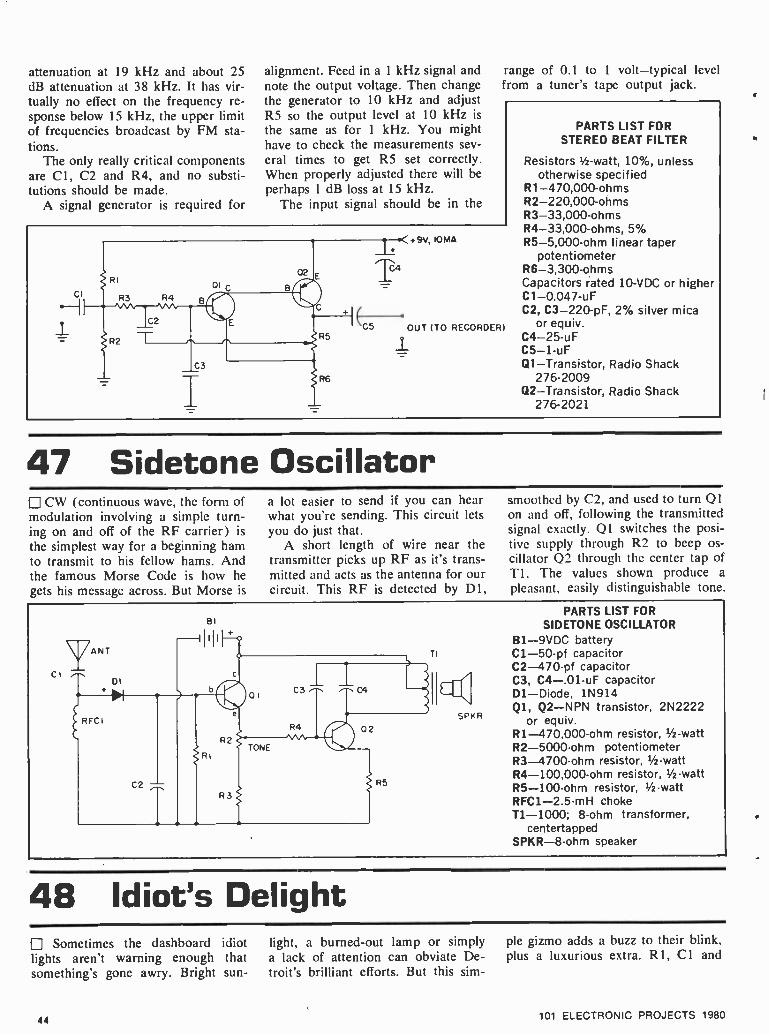
attenuation at 19 kHz and about 25 dB attenuation at 38 kHz. It has vir- tually no effect on the frequency re- sponse below 15 kHz, the upper limit of frequencies broadcast by FM sta- tions.
The only really critical components are Cl, C2 and R4, and no substi- tutions should be made.
A signal generator is required for
alignment. Feed in a 1 kHz signal and note the output voltage. Then change the generator to 10 kHz and adjust RS so the output level at 10 kHz is
the same as for 1 kHz. You might have to check the measurements sev- eral times to get R5 set correctly. When properly adjusted there will be perhaps 1 dB loss at 15 kHz.
The input signal should be in the
range of 0.1 to 1 volt -typical level from a tuner's tape output jack.
CI
+9V, IOMA
C5 OUT (TO RECORDER)
PARTS LIST FOR STEREO BEAT FILTER
Resistors 1/2 -watt, 10 %, unless otherwise specified
R1- 470,000 -ohms R2- 220,000 -ohms R3- 33,000 -ohms R4- 33,000 -ohms, 5% R5 -5,000 -ohm linear taper
potentiometer R6- 3,300 -ohms Capacitors rated 10 -VDC or higher Cl -0.047-u F
C2, C3- 220 -pF, 2% silver mica or equiv.
C4 -25 -uF C5 -1 -uF Ql-Transistor, Radio Shack
276 -2009 Q2- Transistor, Radio Shack
276 -2021
47 Sidetone Oscillator CW (continuous wave, the form of
modulation involving a simple turn- ing on and off of the RF carrier) is
the simplest way for a beginning ham to transmit to his fellow hams. And the famous Morse Code is how he gets his message across. But Morse is
a lot easier to send if you can hear what you're sending. This circuit lets you do just that.
A short length of wire near the transmitter picks up RF as it's trans- mitted and acts as the antenna for our circuit. This RF is detected by Dl.
smoothed by C2, and used to turn Q1 on and off. following the transmitted signal exactly. Ql switches the posi- tive supply through R2 to beep os- cillator Q2 through the center tap of T1. The values shown produce a
pleasant. easily distinguishable tone.
yANT C
DI +
} RFC(
BI -IIII+
C2
RI
1 R2
R3
of
TONE
lI TI
PARTS LIST FOR SIDETONE OSCILLATOR
B1 -9VDC battery C1 -50 -pf capacitor C2- 470 -pf capacitor C3, C4- .01 -uF capacitor
C3
R4
C4 Dl-Diode, 1N914 Ql, Q2 -NPN transistor, 2N2222
or equiv. R1- 470,000 -ohm resistor, 1/2 -watt 02
SPKR
R5
R2- 5000 -ohm potentiometer R3 -4700 -ohm resistor, 1/2-watt R4- 100,000 -ohm resistor, 1/2 -watt R5- 100 -ohm resistor, 1/2 -watt RFC1- 2.5 -mH choke T1 -1000; 8 -ohm transformer,
centertapped SPKR -8 -ohm speaker
48 Idiot's Delight Sometimes the dashboard idiot
lights aren't warning enough that something's gone awry. Bright sun-
44
light, a burned -out lamp or simply a lack of attention can obviate De- troit's brilliant efforts. But this sim-
ple gizmo adds a buzz to their blink. plus a luxurious extra. Rl, Cl and
101 ELECTRONIC PROJECTS 1980
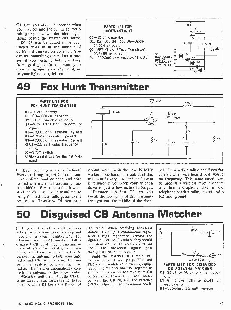
Q1 give you about 7 seconds when you first get into the car to get your- self going and let the idiot lights douse before the buzzer can sound.
D1 -D5 can be added to or sub- tracted from to fit the number of dashboard dimwits on your car. You can use something other than a buz- zer, if you wish, to help you keep from getting confused about your door being ajar, your key being in, or our lights being left on.
PARTS LIST FOR IDIOT'S DELIGHT
C1 -15-uF capacitor D1, D2, D3, D4, D5, D6- Diode,
1N914 or equiv. Q1 -FET (Field Effect Transistor),
2N5458 or equiv. R1- 470.000 -ohm resistor, '2-watt
TO UNGROUNDED SIDE OF DASHBOARD IDIOT LIGHTS
R
ci
D5
49 Fox Hunt Transmitter PARTS LIST FOR
FOX HUNT TRANSMITTER
B1 -9 VDC battery Cl, C3- .001 -uF capacitor C2 -90-pF variable capacitor Q1 -NPN transistor, 2N2222 or
equiv.
ANT RFC I
C2 FRED
1 xTAL
01
e
R1- 10,000-ohm resistor, 1/2-watt SI
R2-470 -ohm resistor, 1/ -watt R3- 47,000 -ohm resistor, 1 /2-watt R2 R3
RFC1 -2.5 mH radio frequency choke
RI CI C3 BI
S1 -SPST switch XTAL -crystal cut for the 49 MHz
band
Ever been to a radio foxhunt? Everyone brings a portable radio and a very directional antenna and tries to find where a small transmitter has been hidden. First one to find it wins. And here's just the transmitter to bring this old ham radio game to the rest of us. Transistor 01 acts as a
crystal oscillator in the new 49 MHz walkie- talkie band. The output of this oscillator is very low, and no license is required if you keep your antenna down to just a few inches in length.
Trimmer capacitor C2 lets you tweak the frequency of this transmit- ter right into the middle of the chan-
nel. Use a walkie talkie and listen for carrier; when you hear it best, you're on frequency. This same circuit can be used as a wireless mike. Connect a carbon microphone, like an old telephone handset mike, in series with R2 and ground.
50 Disguised CB Antenna Matcher If you're tired of your CB antenna
acting like a beacon to every creep and hoodlum in your neighborhood (or wherever you travel) simply install a disguised CB cowl mount antenna in place of your car's existing auto an- tenna, and then use this matcher to connect the antenna to both your auto radio and CB, without need for any switching system between the two radios. The matcher automatically con- nects the antenna to the proper radio.
When transmitting on CB, the CI /L1 series -tuned circuit passes the RF to the antenna, while R1 keeps the RF out of
101 ELECTRONIC PROJECTS 1980
the radio. When receiving broadcast stations, the C1 /LI combination repre- sents a high impedance, keeping the signals out of the CB where they would be "shorted" by the receiver's "front end." The broadcast signals pass through R I to the auto radio.
Build the matcher in a metal en- closure. Jack Jl and plugs PLI and PL2 should match your existing equip- ment. The matcher must be adjusted to your antenna system for maximum CB performance. Connect an SWR meter between the CB rig and the matcher (PL2), adjust CI for minimum SWR.
JI RI
560e
LI c1
30 OR 50 p PARTS LIST FOR DISGUISED
CB ANTENNA MATCHER C1 -30 -pF or 50 -pF trimmer capa-
citor L1 -RF choke (Ohmite Z -144 or
equivalent) R1- 560 -ohm, 1.2 -watt resistor
PI
az
45

51 Crystal Checker A fast way to see if the crystal from
your transmitter or receiver is proper- ly "active" is to compare its output against that of a known good crystal. This crystal checker will handle both
PARTS LIST FOR
CRYSTAL CHECKER
B1 -9 -volt transistor radio battery C1 -50 -pF disc capacitor,
100 VDC or better C2- 0.005 -uF disc capacitor,
25 VDC or better C3 -33 -pF disc or mica capacitor,
100 VDC or better D1- Diode, 1N60 M1- Meter, 0 -1 mA DC PB1- Normally open push button
switch Q1 -NPN transistor, HEP -50
(Radio Shack 276 -2009) R1- 100,000 -ohm, 1/2-watt resistor R2- 10,000 -ohm, 1/2-watt resistor RFC- 2.5 -mH RF choke S01- Socket to match crystals,
see text
fundamental and overtone type crys- tals. Socket SOI should match the pins on your crystals. If you use more than one type of crystal, install two (or more) sockets in parallel. The unit can be assembled in any type of cabinet.
To test a crystal's activity, first plug in a known good crystal, depress push button switch PB1 and note the me- ter reading. Then install the ques-
tionable crystal, press PB 1 and note its meter reading; if it's good its out- put should approximate that of the reference crystal. Take care that you don't compare apples with oranges; the reference crystal should be the exact same type as the crystal to be tested. If good crystals drive the meter off scale, install a 1000 -ohm, 1/2-watt, 10 percent resistor in series with meter MI.
IOOK
SOI
o o
jR2 ICI
01 HEP -50
bi
0K
PBI BI
RFC I 9VDC
I I cz 1I
T005uF
52 Quick Draw Game Okay, podner, the fuss one to push
the button lights the light on his side, and blocks the other light from turn- ing on.
You can yell "draw" by closing SI. But instead of a switch, you can find a trickier way of closing the contacts.
Try rolling a steel ball hearing down a channel with the contacts on the bottom. When the ball completes the circuit, go for your trigger but- tons. Or you can just leave SI closed. Once both "triggers" (S2 and S3) are released, this game is automati- cally set to he played again.
PARTS LIST FOR QUICK DRAW GAME
B1 -6 -15 VDC battery LED1, LED2 -Light emitting diodes Q1, Q2 -NPN transistors (2N2222
or similar) R1, R4-150-390-ohms resistors,
' -watt R2, R3-22,000-56,000-ohm re-
sistors, 1/2 -watt S1 -SPST switch (see text) S2, S3- Normally open momentary,
or micro, switches
53 12 to 9 for Transistors When your auto radio poops out,
this regulated voltage adapter keeps you in music from a transistor por- table until you're ready to climb under the dash to get at the trouble and fix it.
Power is taken from the 12 -volt
46
auto battery through a cigar lighter plug. The zener diode can be anything with an approximate rating of 9 volts. For example, you can use a 9.1 -volt unit (common in Zener kits), or even one rated at 8.6 volts. Make certain the Zener is correctly installed; the
end marked with a band is th.. cathode.
The adapter is rated for a current of 12 mA maximum. A good rule of thumb is that a radio powered by a
Burgess type 2U6 battery can safely operate on the adapter.
101 ELECTRONIC PROJECTS 1980

12V DC +
PLI RI
PARTS LIST FOR 12 TO 9 FOR TRANSISTORS
C1- 0.05 -uF, 400 -VDC capacitor D1 -1 -watt, 9.1 -V Zener diode -
HEP -104 (Radio Shack 276 -562) PLI- Cigarette lighter plug
(Calectro N4 -029) R1- 150- ohm,'/2 -watt resistor
DI
+ 9V,12 mA
54 Audio Utility Amp This circuit may look familiar if
you're in the habit of glancing at the schematics of your portable radios and recorders. This is a very popular way of getting a signal to a speaker. Transistor Q 1 acts as a driver for complementary pair Q2 and Q3. 02 and Q3 take turns conducting as they follow the input signal, so they can deliver a healthy signal through C2 to
TI. TI is suggested to reduce the loading that a low speaker impedance would cause if connected directly be- tween C2 and ground; a higher im- pedance speaker or headphone could connect directly.
You can also use this circuit as a signal tracer to listen in on what's happening inside some of the other circuits on these pages. Just clip a
lead between the minus leads of both projects and use one lead of a .01 microfarad capacitor in series with the input as a probe.
PARTS LIST FOR AUDIO UTILITY AMP
B1 -9 VDC battery C1 -15 -uF electrolytic capacitor,
15 VDC (or greater than needed)
C2- 100 -uF electrolytic capacitor, 15 VDC (or greater than needed)
Q1, Q2 -NPN transistor, 2N3904 or equiv.
Q3 -PNP transistor, 2N3906 or equiv.
R1- 1- Megohm potentiometer R2- 270,000 -ohm resistor, 1/2 -watt R3- 1200 -ohm resistor, 1/2 -watt R4- 100 -ohm resistor, 1/2 -watt S1 -SPST switch T1- 500:8 -ohm matching trans-
former SPKR -8 -ohm speaker
55 Attache Alarm Who knows what evils lurk, ready
to pilfer the Twinkles out of your attache case when you're not looking? This squealer does. Because when you arm the alarm by turning on SI,
the lightest touch will set it off. More accurately, the touch of light. Light striking QI turns on transistor switch 02, which energizes oscillator 03 -04. And that blows the whistle.
s
RI
01
e
04 b
SPEAKER
PARTS LIST FOR ATTACHE ALARM
B1 -9 VDC battery C1- .01 -uF capacitor Q1- Photoelectric transistor, FPT
100 or equiv. Q2 -NPN transistor, 2N2222 or
equiv. Q3 -NPN transistor, 2N3904 or
equiv. Q4 -PNP transistor, 2N3906 or
equiv. R1-2200-ohm resistor, 1/ -watt R2- 100,00 -ohm resistor, 1/2-watt S1 -SPST switch SPKR -8 -ohm speaker
101 ELECTRONIC PROJECTS 1980 47

56 Pro Burglar Alarm 0 Almost without exception, profes- sional burglar alarms are the so- called "supervised" type, meaning a closed circuit loop in which current, no mat- ter how low a value, always flows so that cutting any of the wiring causes the alarm to sound. Early closed cir- cuit alarms were entirely relay operated, and a high resistance which developed anywhere in the circuit usually caused the alarm to false -trip, which always seemed to happen in the wee hours of the morning. Solid -state supervised cir- cuits, such as this Pro Burglar Alarm, are relatively insensitive to the high re- sistance developed in contacts through normal aging.
The switches shown as "N.C. (nor- mally closed) Switch" can be any nor- mally closed or continuous device, such as window foil. Battery B1 is a 6 -volt lantern battery which will give service for almost as long as its shelf -life be-
cause the continuous current drain is only about 100 AA. Once the alarm is
tripped, it can be turned off only by opening master power switch SI, or "bell stop" PB1, a normally -closed pushbutton switch. (Both switches should be concealed.)
To adjust: Open the protective cir-
cuit. While measuring the voltage across R1, advance R2 so the meter reading rises from zero towards 1 -volt. At less than l -volt, the alarm bell should trip. It it doesn't, you have made an as- sembly error. Finally, adjust R2 for a 1 -volt reading, disconnect the meter and restore the protective circuit.
PARTS LIST FOR PRO
A1-6 -VDC alarm bell or siren B1 -6 -volt lantern battery C1- 50 -uF, 6 -VDC electrolytic ca-
pacitor Q1- 2N2222A NPN transistor or
BREAK WIRE HERE TO INSTALL EXTRA PROTECTION SWITCHES
R2 250K
R3 47K
I+ _ B I
6VDC
SCR I
NC NC SWITCH SWITCH
BURGLAR ALARM
equivalent R1- 1,000 -ohm, 1/2 -watt resistor R2- 250,000 -ohm linear taper po-
tentiometer R3- 47,000 -ohm, 1/2 -watt resistor
SCR1-GEMR-5 silicon controlled rectifier
S1-SPST switch S2- normally -closed SPST pushbut-
ton switch
57 Square Wave Generator OUTPUT A
OUTPUT B
OUTPUT C
RI
OUTPUT C 51/
BI
t2 t3
t I = t2 = t3 WHEN RI = R2 = R3
CI=C2=C3 AND R4=R5=R6
Here is a versatile square wave generator capable of surprising per- formance. It can deliver clock or switching pulses, act as a signal source, and more. And because the outputs take turns switching, it can be used as a simple sequence gen- erator or as a multiple -phase clock.
48
The component values indicated will support a range of output fre- quencies from a few p.ilses per second up into the high audio range. And this square wave ouput is rich in har- monics. If you use a 5 -volt power supply, this circuit can trigger TTL logic directly.
PARTS L ST FOR SQUARE WAVE GENERATOR
B1 -6.15 VDC battery Cl, C2, C3 -.5 -uF capacitor Q1, Q2, Q3 -NPN general purpose
transistor (2N2222, 2N3904 or equiv.)
R1, R2, R3- 500 - 2700 -ohm resis- tors, 1/2-watt
R4, R5, R6-10,000-47,000-ohm resistor, 1/2 -watt
S1 -SPST switch
101 ELECTRONIC PROJECTS 1980

58 Latching Burglar Alarm Open a fancy commercial burglar
alarm and all you'll find inside is this ordinary relay latching circuit.
The input terminals are connected to parallel -wired normally open (N.O.) magnetic switches, or wire - type security switches stretched across a window that close a bell contact circuit when the wire is pushed or pulled.
When a security switch closes the series battery circuit, relay K1 pulls in. One set of contacts closes the alarm bell circuit, while the second set "latches" the battery circuit. Even if the security switches are opened, the alarm remains on. To disable the alarm, or for reset, install a con- cealed switch in series with one bat- tery lead.
TO ADDITIONAL
SWITCHES SI
BI - 6V DC
PARTS LIST FOR LATCHING BURGLAR ALARM
B1 -6 -V lantern battery BELL -6 -VDC alarm bell
BELL
K1 -6 -VDC dpst relay S1 -Spst n.o. switch
59 Wide Range Voltage Pilot Believe it or not, this simple tester
will verify voltages between 2 and 120 Volts, AC or DC -and tell you which!
It's easy to understand if you can think of the filament of a small night - light bulb as being a wirewound re- sistor. It provides the current limiting that LED 1 and LED 2 need to op- erate safely. And, of course, when the voltage at the probe tips is high enough, I1 lights as well.
You can choose different colors for LED 1 and LED 2 and the probe tips for very quick polarity indica- tions in the case of DC voltages. And seeing both LEDs glow is quick con- firmation of an AC voltage.
PARTS LIST FOR WIDE RANGE VOLTAGE PILOT
I1 -Bulb, 71/2 watts at 120-volts LED1, LED2 -Light emitting diode
II
II
LED I 0ó LED2
60 Dry -Cell Charger This circuit in a fancy commercial
package will cost you about $5. Build a lamp bulb charger yourself and 500 may just about do it.
The lamp maintains constant charg- ing of approximately 20 mA through one to four 1.5 -volt batteries. But you can go as high as 22.5 volts for either batteries in series or a single battery.
Give small penlight batteries about
101 ELECTRONIC PROJECTS 1980
117
VAC UP TO
_1+ FOUR I.5V BATTERIES
-r .- -J
PARTS LIST FOR DRY -CELL BATTERY CHARGER
I1 -No. S -6, 6 -watt candelabra lamp SR1- 400 -PIV, lA silicon rectifier
(Lafayette Radio Electronics 32R08824 or equiv.)
10 hours charge, the C and D cells about 20 hours. Yes, you can recharge
NICads stamped with a charge rate of approximately 20 to 25 mA.
49

61 Photoflood Dimmer #2 Professional quality photographic
lighting requires complete control of the studio lights, and that's just what you'll get with the pro -type, full -range 500 - watt dimmer. Each one can handle one 500 -watt #2, or two 100 -watt #1 photoflood lamps, and the lighting range can be adjusted from full off to full on.
Triac Q1 must be mounted to a large heat sink, preferably the metal cabinet used to house this dimmer. Make cer-
tain you insulate Q1 from the cabinet. Fuse FI inuct be used, otherwise, the
surge current that occurs when 500 - watt photofloods burn out will instantly destroy Q1. FI must be a fast -acting fuse such as the type 8AG. The slower fuses such as the 3AG and the slo -blo offer no protection. Switch SI is part
of intensity adjustment R1, and RI should be wired so it represents maxi- mum resistance just before SI switches off. (While SI cannot normally handle a 500 watt load, in this circuit, it switches when the lamp is off and has no trouble handling any size photo- flood.)
PARTS LIST FOR PHOTOFLOOD DIMMER t1
Cl, C2- 0.01 -uF, 50 -VDC ceramic disc capacitor
D1- HEP -R2002 bi- directional trig- ger diode
F1 -8AG 5 -Amp fast -acting fuse Q1- HEP -R1723 Triac R1- 100,000 -ohm, linear taper po-
tentiometer w/SPST switch R2- 1,000 -ohm, 1/2-watt resistor R3- 15,000 -ohm, 1/2-watt resistor S1 -SPST switch, part of R1
RI IOOK
5-AMP FAST ACTING FUSE
II St I OR il 2 PHOTOFLOOD
RI 723
DI R2002
C 120 VAC
62 Voltage Controlled Oscillator Unijunction transistors are very
interesting. They love to be used in oscillators, and it doesn't take too many parts or very much coaxing to get their sawtooth outputs going. This little squealer will tell you how much voltage it's connected to. The higher the voltage, the lower frequency out- put you'll hear. 5 or 6 Volts should start its high squeal going; 25 or 30 volts and it'll be ticking like a metro- nome. You can take advantage of this voltage to frequency conversion and use this circuit as an audible volt- meter. Or, with a resistor across the input, it can be an audible current
PARTS LIST FOR VOLTAGE CONTROLLED
OSCILLATOR
C1-.5-2.2-uF capacitor R1- 10,000- 47,000 -ohm resistor.
1/2-watt R2-82-150-ohm resistor, 1"2-watt Q1- unijunction transistor (2N-
2646 or equiv.) SPKR -840 -ohms
meter. For a slightly stranger effect, con-
nect a large value capacitor (say 50- 100 uF with a voltage rating larger than the voltages you intend to ap-
ply) . You'll hear a swooping effect. Many different components can be placed across the input for different effects when voltage is applied. Ex- periment and have fun.
63 Highway Nightfall Alert When it gets dark out, you don't
always notice the change. So it isn't hard to get caught driving in the dark without your headlights on. This little project buzzes a friendly reminder until you turn the lights on, turn the
50
car off, or morning comes. K1 turns on with your headlights.
When it's on, it disables the rest of the circuit. So a warning can only sound with your headlights off. As long as light strikes Q1, 02 remains
on, holding Q3 off. Voltage divider R5 -R7 -R8 determines the turn -on point for Q3. Q3 drives K2, which triggers a buzzer or other signalling device. A photoconductor may be substituted for R1 -01, if desired.
101 ELECTRONIC PROJECTS 1980

PARTS LIST FOR HIGHWAY NIGHTFALL ALERT
D1, D2- diode, 1N914 or equiv. K1 -SPDT relay, 12VDC K2 -SPST relay, 12VDC Q1- Phototransistor, FPT100 or
equiv. Q2 -NPN transistor, 2N3904 or
equiv. Q3 -NPN transistor, 2N2222 or
equiv. R1, R4, R7- 4700 -ohm resistor,
1/ -watt R2- 560 -ohm resistor, 1/2 -watt R3, R5, R8- 10,000 -ohm resistor,
1/2 -watt R6- 220 -ohm resistor, 1/2 -watt
D2 THRESHOLD +
64 Transistor Checker
PARTS LIST FOR TRANSISTOR CHECKER
B1 -9 VDC battery LED1, LED2 -Light emitting diode R1- 1000 -ohm resistor, 1/2 -watt R2- 470 -ohm resistor, 1/2-watt S1 -DPDT switch S2- Momentary push button
switch SO1- Transistor socket
NPN
PNP
It's pushbutton -easy to check tran- sistors with this tiny marvel. Just plug the transistor in and push S2. If its good and you set the PNP -NPN switch SI properly, the appropriate LED
will light. Don't know the type? That's okay.
Plug it in and try both SI switch positions while you watch for the appropriate LED to light. You can
even test diodes using the collector - emitter leads on the socket. The col- lector- emitter leads can also be used to check continuity.
65 Angler's Bite Booster PARTS LIST FOR ANGLER'S BITE BOOSTER
Click -click might not sound like much to you but to a fish it's the dinner bell. That's the lure of this electronic circuit. Shove the whole works in a watertight container, low- er it over the side, and wait for the fish to hit the hooks.
For proper operation TI must be subminiature type about half as large as your thumb. El must be a crystal headphone.
101 ELECTRONIC PROJECTS 1980
B1, B2 -1.5 -V AAA battery Cl, C2- 50 -uF, 12 -VDC electrolytic
capacitor E1- Crystal earphone Q1- Motorola HEP -230 pnp
transistor R1- 5000 -ohm pot R2- 27,000 -ohm, 1/4-watt resistor S1 -Spst switch, part of R1 T1- Subminiature transistor output
transformer; 500 -ohm center
ON-OFF I BI 82 _±] 1_±.1
C2
cl
tapped primary to 8 -ohm secondary
51

66 Turn -On Delay Turn the switch on and the cir-
cuit you're controlling (LOAD) won't turn on until 10 seconds later with this UJT delay. The SCR is the "switch" that eventually permits cur- rent to flow through the load. But the SCR won't turn on until the UJT timer circuit delivers a pulse to its gate. This happens after a time delay determined by the product.
Choose a value for SCR1 that can easily handle the maximum current the load will draw, plus a margin for safety, and the voltage of the power supply, plus a margin for safety. For a 9 -12 Volt circuit drawing up to 1/2
amp or so, a 20 Volt 1 Amp SCR should do nicely. Since Si, when turned off, interrupts the flow of cur- rent through the SCR, turn -off for the load happens immediately.
PARTS LIST FOR TURN -ON DELAY
C1- 220 -uF capacitor Q1 -UJT (Unijunction Transistor),
2N2646 or equiv. R1- 47,000 -ohm resistor, '/2 -watt
+ V o-
-v o
S I .o
R2 -22 ohm resistor, '2 -watt SCRI-See text S1 -SPST
I
RI
bl
01
CI b2
R2
( +) LOAD' THE CIRCUIT YOU ADD THIS TO.
( -)
SCRI
67 A Vom Thermometer Almost all electronic components
change characteristics as temperatures change. In the case of silicon diodes, like the 1N914, the characteristic that changes is the amount of forward voltage drop.
Diodes aren't perfect conductors, you see, because they must take ad- vantage of the bias (voltage) across a semiconductor junction (the place where the two different kinds of semi- conductor material, p and n, meet) in order to operate.
Almost every semiconductor device shows a junction voltage drop of about ' Volt when forward biased, as the diodes here are.
So if you string eight diodes in series, like these, and measure the voltage across the string on the 5 Volt scale of your VOM, you'll see the voltage varying up and down around
4 Volts as you change the tempera- ture the diodes are exposed to.
You could calibrate a separate meter to give you actual degree read- ings, but for many purposes, just knowing the temperature is changing is enough.
RI
- Bi
PARTS LIST FOR A VOM THERMOMETER
B1 -9 VDC battery D1, D2, D3, D4, D5, D6, D7, D8,
09- Diode, 1N914 or equiv. R1- 4700 -ohm resistor, '2-watt S1 -SPST switch
+
VOM 5 VOLT RANGE
Di
02
D3
D4
D5 * 06
D7 +
D8
68 Overvoltage Protector Too high a voltage can damage
any number of electronic compo- nents. Many other components can
52
withstand high voltages, hut only for a limited time. This circuit provides either protection against too much
voltage in much the same way a cir- cuit breaker protects against too much current, or a warning that an
101 ELECTRONIC PROJECTS 1980

overvoltage condition is occurring. In the Breaker position, power is
applied to the protected circuit only so long as relay K1 is not energized. K1 will energize whenever the input voltage exceeds the Zener voltage of diode D1, because above its zener voltage, a reverse -biased Zener diode like this one will conduct. In the Buzzer position, power remains ap- plied to the circuit through the relay itself. When an overvoltage is present, the relay pulls in, disconnecting itself, which allows it to release and re -es- tablish connection, which causes it to pull in and break connection and so on- exactly the action of a buzzer. And that's exactly the sound the relay
POWER SI
BUZZER v
BREAKER
DI
+ POWER O TO
CIRCUIT
PARTS LIST FOR OVERVOLTAGE PROTECTOR
D1 -Zener diode, 9.1 Volt at '/4-
watt D2- Diode, 1N914 or equiv. K1- Relay; 12 -volt, coil at least
600 -ohm S1 -SPDT switch
will make -with enough noise gener- ated to carry the buzz into the audio
and IF circuits of almost anything connected or nearby.
69 High Impedance Mike Amplifier This high -to -low impedance
converter will let you use a high impedance crystal, ceramic or dy- namic microphone with conventional (around 5K) microphone inputs. It will also let you use a high impe- dance mike over a longer run of cable with less danger of introducing
hum. Q1 is a general purpose N- channel
JFET, like the Siliconix 2N5458, Motorola MPF102 or similar. Choose R 1 to match the impedance of your microphone.
If you choose to mount this circuit in or near the microphone case
(where it will do the most good), and the microphone is a push -to -talk type, investigate using the PTT switch in place of SI. This may work better
'if SI is placed in the negative battery lead rather than the positive (as shown) .
MIC
m
CI
PARTS LIST FOR HIGH IMPEDANCE MIKE AMPLIFIER
- BI
/77
B1 -6 -15 VDC battery Cl, C3- .001- .01 -uF capacitors C2 -25- 100 -uF Q1 -N- channel JFET (Junction
Field Effect Transistor) (2N5458 or similar)
R1 -1 -10 Megohm resistor, 1/2 -watt R2 -1800- 330 -ohm resistor, 1/2-
watt R3- 4700 -10,000 -ohm resistor, 1/2-
watt S1 -SPST switch (see text)
70 Zener Regulator When the output from an AC
power supply is too high for a solid - state project, chop it down to size with a zener diode voltage regulator and keep it on the button.
To calculate R, first add the load current and 1/20 of the load current for the zener's idling current. Then use Ohm's Law (R = E /I) to calcu- late R. The resistor's power rating
101 ELECTRONIC PROJECTS 1980
should be twice the calculated power .
The power rating for the zener diode is determined by the voltage across the diode squared, divided by diode's nominal internal resistance. You can calculate the internal resis- tance by working backwards from the zener's power rating. As an example: a 9 -volt, 1 -watt zener would have a nominal internal resistance of R
HIGH DC IN
RI (SEE TEXT)
LOW DC OUT
E2 W, 81 1, or 81 ohms. It's no precisely accurate, but close enough
53

71 Balanced Input Mike Preamp fl Once the length of a "single ended" (one shielded wire) microphone cable exceeds 25 -feet, it becomes highly sus-
ceptible to hum and noise pickup. One way the pros get around the problem is by using low- impedance balanced - output microphones. The Low -Z mike is less susceptible to noise pickup to start with, and what noises picked up by the line are picked up equally in both wires, so they cancel if the
mike feeds a balanced input amplifier. About the easiest way to get a bal-
anced input is to use an operational amplifier as a preamp, because the op amp starts out with a dülerential (bal- anced) input. Virtually any op amp can be used, although the Signetics SE 'NE- 531 is a good choice because it's very stable. In addition to providing a bal- anced. noise -cancelling input, this cir- cuit delivers a nominal 40 dB gain.
Aside from using a metal enclosure, there is no special assembly precaution, other than installing Cl and C2 as
close as possible to the IC terminals. The 531 is available in both the "round" package shown and in a DIP. Either packaging type can be used. Any microphone with a balanced output up to 1000 ohms can he used, though the more common impedances of 150 to 600 ohms will produce optimum fidelity.
PARTS LIST FOR BALANCED MIKE PRE -AMP
Cl, C2- 0.1 -uF, 15 -VDC mylar ca- pacitor
C3- 100 -pF, 500 -VDC ceramic disc capacitor
C4- 0.22 -uF, 15 -VDC mylar capaci- tor
R1, R2- 470 -ohm, 1/2 -watt resistor, 5% tolerance
R3, R4- 47,000 -ohm, 1/2 -watt resis- tor, 5% tolerance
U1- Signetics NE or SE -531 op amp
+9VDC
RI 150 -6000 MIKE 470
R4 47 K
C4 0 22 HI- Z OUTPUT
O 50,0009 1
1- SHIELDED TWISTED PAIR
-9V L
C2 = 0. I
3 2 4
8 6 7
5 U I BOTTOM VIEW
72 Doorknob Security Alarm Here's security for the traveler.
Just connect this alarm to the door- knob of your motel room and a loud buzzer will sound if anyone touches the doorknob.
Transistor circuit Q 1 is an oscilla- tor with a connection through bind-
ing post BPI to the doorknob. As long as Q 1 oscillates, its rectified out-
put is applied to 02 which holds the SCR 1 gate almost at ground poten-
PARTS LIST FOR DOORKNOB SECURITY ALARM
B1 -6 -volt battery, Burgess Z4 or equiv.
BP1- Binding post BU1 -6 -volt buzzer Cl, C2- 0.05 -uF disc capacitor,
25 VDC or better C3 -47 -pF silver mica capacitor
(Allied Electronics 782 -0860) C4- 300 -pF trimmer capacitor C5- 0.05 -uF, 25 VDC capacitor C6 -50 -uF electrolytic capacitor,
25 VDC or better 01, 02- Diode, 1N60 D3- Diode, 1N914
cl .05uF
LI
I
C3 IBPI 50pF I c5
s .OIuF
Di 2N3394
c4 25-250pF
A
C2 y .05uF R2 R3
10K 1K
R4 56011
D2 IN60
IN914
PB1
Dl IN60 02
2N3391
L1 -15 -uH adjustable RF coil (Miller 4205, or equiv.)
PB1- Pushbutton switch (reset) Q1- 2N3394 Q2- 2N3391 R1-47,000-ohm, 1/2 -watt resistor R2- 10,000 -ohm, 1/2 -watt resistor
C6 50uF
R3, R6- 1000 -ohm, 1/2-watt resistor R4 -560 -ohm, 1/ -watt resistor R5- 5600 -ohm, 1/2 -watt resistor 51-Switch, spst (on -off) SCR1-800-mA/30-V silicon
controlled rectifier, HEP R1001
54 101 ELECTRONIC PROJECTS 1980

tial. When someone touches the door- knob, hand capacitance "kills" the oscillator, thereby removing that cut- off (holding) bias from the SCR1 gate; the SCR conducts and sounds alarm buzzer BUI. The alarm can only be turned off by opening reset
switch PB 1. The alarm should be assembled in
a small metal cabinet with insulated binding post BP1 at the top. A small wire loop attached to BP1 secures the alarm to the doorknob -the alarm actually hangs on the knob. To adjust,
carefully set C4 in small increments until touching your finger to BPI causes the buzzer to sound. If C4 is overadjusted, hand capacitance will not "kill" the oscillator. Best opera- tion is obtained if the door is made of wood.
73 The Bamboozler Officially, this is a slow speed
astable multivibrator with state -indi- cating photo -optic outputs. Unoffi- cially, it's just a circuit to alternately flash two L.E.D.s. But you don't have to tell anybody that. Tell them it's counting Ekno Rays from the planet Nerd. Or it remotely controls your pacemaker. Or it can tell a person's innermost secrets. Or you'll think of something. R3 limits the current the whole circuit can draw. If you find the flashing too dim or unreliable. reduce the value of R3 to 150, 100 or 47 Ohms. If you could handle even dimmer blinks, in- crease R3 to a maximum of about 100 Ohms.
You could also use different color LEDs. add a magnetic reed switch in series with each capacitor, and hide a magnet between your fingers. Then. by careful positioning, you can con- trol whether both flash, one stays on or both stay on.
PARTS LIST FOR THE BAMBOOZLER
B1 -9 VDC battery Cl, C2 -10 -uF capacitor LEDI, LED2 -Light emitting diode Q1, Q2 -PNP transistor, 2N3906
or equiv.
R1, R2- 47,000 -ohm resistor, /- watt
R3- 220 -ohm resistor, /-watt S1 -SPST switch
74 Rocker's Mike Booster !] Between the lead and rhythm gui- tars, and the organ or synthesizer, the lead vocalist's mike often gets buried under the instruments if they all use a common amplifier. One way to get the vocalist up and out front is to give the mike some extra sock with a preamp. This one, specifically designed to handle most of the impedances commonly used by rock -group mikes, will give enough extra gain to project the singer's voice out to the last row of the balcony! Build it any way you wish, just as long as it's inside a metal cabinet.
PARTS LIST FOR ROCKER'S MIKE BOOSTER
B1 -9 -volt transistor radio battery, see text
C1 -10 -uF capacitor
BI 9vDC
C2- 0.1 -uF, 10 -VDC mylar capacitor 11, J2 -jacks to match existing
cables Q1- HEP -S0025 NPN transisto R1- 43,000 -ohm, 1/2 -watt resistor
R4 100K
J2 OUTPUT
R2- 430,000 -ohm, Y2-watt resistor R3- 10,000 -ohm, 1/2-watt resistor R4- 100,000 -ohm, audio taper po-
tentiometer w /SPST switch S1 -SPST switch, part of R4
101 ELECTRONIC PROJECTS 1980 55

75 Twang -A -Matic It seems no one cares for the sound
of a plain, unadorned guitar. First they added fuzz. then big -boom bass, next it was reverberation and scream- ing highs. Now the in sound is twang, a guitar sound that more or less ap- proximates a banjo or mandolin. A Twang -A -Matic produces these un- usual sounds from an ordinary electric guitar by cutting the bass, severely distorting the midband and highs, and then amplifying the distortion. It might read "bad" to you, but it sure sounds good!
You can assemble the Twang -A- Matic in any type of cabinet. Switch Si cuts the effect in and out while switch S2 turns the unit on and off. Output control R7 should be set so the Twang -A -Matic has the same vol- ume level as the straight guitar feed - through. Various degrees of twang are obtained by varying the output so the guitar picks up with the level controls built into the guitar.
Ji INPUT
R7 IJ2 50K , OUTPUT
PARTS LIST FOR TWANG -A -MATIC
B1 -9 -volt battery (Eveready 246 or equiv.)
C1- 0.001 -uF disc capacitor 25 VDC or better
C2 -2 -uF electrolytic capacitor, 15 VDC or better
C3 -1 -uF electrolytic capacitor, 15 VDC or better
C4- 0.005 -uF disc capacitor, 15 VDC or better
11, 12 -Phone jack
Q1, Q2 -NPN transistor, 2N3394 R1, R5 -1 megohm, 1/2 -watt resistor R2- 10,000, 1/4-watt resistor R3- 20,000 -ohm, 1/4-watt resistor, 5
percent R4 -18 -ohm, 112 -watt resistor R6- 4700 -ohm, 1/2-watt resistor R7- 50,000 -ohm potentiometer S1- Switch, spdt (twang in -out) S2- Switch, spst (on -off)
76 Computer Recording Attenuator Most personal computers use a low -
cost cassette recorder as the data stor- age medium, the data generally being stored on tape as alternating audio fre- quencies. There is no standard output level for personal computer data signal levels, and the computers rely on the recorder's automatic record level con- trol to prevent tape overload and satura- tion. The auto -level control generally works well. Unfortunately, the signal level from many computers is often suf- ficiently high to overload the recorder's input before the level control gets a chance to work. and thus the storage of data becomes intermittent, or even im-
SHIELDED CABLE
r 1
PI tE--P2 1 ¡ RI
100K
R2 10K
PARTS LIST FOR COMPUTER RECORDING
ATTENUATOR Pl, P2 -plugs to match existing
equipment R1- 100,000 -ohm, 1/4 -watt resistor R2- 10,000 -ohm, 1/4 -watt resistor
possible. If you have trouble recording your
programs, try installing this attenuator cable between the computer's "output to recorder" and the recorder's auxil- iary or high- level input. The 10:1 volt- age ratio of the cable represents a 20 dB signal attenuation, usually just the
right value to prevent overload of the recorder.
Resistors R1 and R2 should be in- stalled directly behind plug PL2. Shield- ed audio cable must be used between PLI and PL2. Plugs PLI and PL2 should match your existing computer and recorder jacks.
77 Current Tattletale Ever have to check a line to see
whether or not any current was flow- ing within it, and which way? Here's an easy answer. Any current flow here will build up a voltage in R1. If the voltage in R 1 is more than
about 2 volts, one or the other (or both, if AC) of the LEDs will light.
Different systems may require dif- ferent values for RI. Use Ohm's Law to calculate R I. For example, if we wanted to know whether or not a
car's taillight bulb had burned out, we could connect this circuit in series with the lamp's supply lead. Assume the particular lamp requires typically 1/2 Amp to light. We then need to know what value for RI will provide
56 101 ELECTRONIC PROJECTS 1980

a 2 Volt drop. Using Ohm's Law, E =IXR, or
R=E /I -2+1 4 Ohms (you would want to use a 4 or 5 Watt resistor to comfortably handle this 1 Watt power dissipation).
In a 100 Volt B+ supply drawing 100 ma, R =E /1 =2 /.100 =20 Ohms.
The circuit drawn above is sensi- tive enough to detect a few milliam- peres of current flow.
PARTS LIST FOR CURRENT TATTLETALE
LEDI, LED2 -Light emitting diode R1, R2, R3- 470 -ohm resistor, 1/2-
watt
RI
R3
LED2
78 Speaker -MIC PARTS LIST FOR SPEAKER -MIC B1 -9 -volt transistor radio battery C1- 4.7 -uF, 10 -VDC electrolytic ca-
pacitor C2- 0.22 -uF, 10 -VDC mylar capa-
citor Q1- general purpose NPN transis-
tor, see text R1- 270,000 -ohm, 1/2 -watt resistor R2- 27,000 -ohm, 1/2 -watt resistor R3 -audio taper potentiometer, see
text S1 -SPST switch
A "junk box" speaker and a general purpose transistor, plus a few other "general purpose" components are all that are required for a high- output microphone substitute. While not hi -fi quality by any stretch of the imagina- tion, the Speaker -Mie handles voice fre- quency signals very well.
Transistor Q l can be just about any general- purpose NPN wtih a Beta of
C2 0 22
SI
about 50 to 150. The speaker can be anything you have lying around of vir- tually any impedance rating in the range of 3.2 to 42 -ohms. If the entire circuit, including battery, is assembled in a small metal enclosure, you'll end up with a hand -sized "amplified micro- phone."
The volume level is adjusted with po- tentiometer R3, which can be any audio taper unit from 50,000 -ohms to 1 -meg- ohm. You can substitute a linear taper potentiometer if you have one lying around, but you'll find the adjustment range is scrunched together on one end of the shaft's rotation.
79 Quick Diode Checker
PARTS LIST FOR QUICK DIODE CHECKER
B1 -9VDC battery LEDI -Light emitting diode R1- 470 -ohm resistor, 1/2 -watt S1 -DPDT switch
B = 9V
LED I
o I v
n i SI
TEST TEER -MI NALS
E
This not only tells you whether or not a diode is good, it checks the polarity for you.
The diode under test completes the circuit through B1, R1 and the LED
101 ELECTRONIC PROJECTS 1980
when inserted in the proper polarity. Switch S1 reverses the polarity of the diode under test. A good diode will light the LED only in one switch position. An open diode will not light it in either position. A shorted
diode will light it in both positions. To use the circuit as a polarity indi- cator, connect the diode to the test terminals. The diagrams above refer to the polarity of the diode when the LED lights in the switch positions.
57
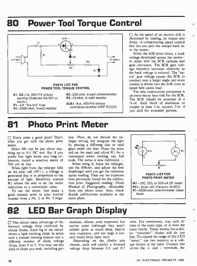
80 Power Tool Torque Control SCR -I
PARTS LIST FOR POWER TOOL TORQUE CONTROL
D1, D2-IA, 400 PIV silicon rectifier (Calectro K4 -557 or equiv.)
F1 -3 -A "Slo -blo" fuse R1 -2500 -ohm, 5 -watt resistor
R2- 250 -ohm, 4 -watt potentiometer R3 -33 -ohm, 1/2-watt resistor
SCR1 -8 -A, 400 -Ply silicon controlled rectifier (HEP R1222)
As the speed of an electric drill is decreased by loading, its torque also drops. A compensating speed control like this one puts the oomph back in- to the motor.
When the drill slows down, a back voltage developed across the motor - in series with the SCR cathode and gate- decreases. The SCR gate volt- age therefore increases relatively as
the back voltage is reduced. The "ex- tra" gate voltage causes the SCR to conduct over a larger angle and more current is driven into the drill, even as
speed falls under load. The only construction precaution is
an extra -heavy heat sink for the SCR. The SCR should be mounted in a
1/4-in. thick block of aluminum or copper at least 1 -in. square; 2 -in. if you drill for extended periods.
81 Photo Print Meter Every print a good print! That's
what you get with the photo print meter.
Meter MI can be just about any- thing up to 0 -1 DC mA. But if you prefer low light levels and long ex- posures, install a sensitive meter of 500 uA or less.
When light from the enlarger falls on the solar cell (PC 1) , a voltage is
generated that is in proportion to the amount of light. Sensitivity control RI allows the user to set the meter indication to a convenient value.
To use the meter, first make a
good normal print in your normal manner from a No. 2 or No. 3 nega-
tive. Then, do not disturb the en- larger setting, but integrate the light by placing a diffusing disc or opal glass under the lens. Place the solar cell on the easel and adjust R1 for a
convenient meter reading, say, full scale. The meter is now calibrated.
When using it, focus the enlarger, use the diffuser, and adjust the lens diaphragm until you get the reference meter reading. Then use the exposure time previously found for the calibra- tion print. Suggested reading: Ilford Manual of Photography, obtainable from any photo store. Also, check Kodak publications available at the same place.
RI
MI
PARTS LIST FOR PHOTO PRINT METER
M1 -100, 250, or 500 -uA DC meter PC1 -Solar cell (Calectro J4 -801) R1- 5000 -ohm potentiometer linear
taper
82 LED Bar Graph Display This circuit takes advantage of the
forward voltage drop exhibited by
silicon diodes. Each leg of the circuit shows a light emitting diode in series
with a current limiting resistor and a
different number of diode voltage drops, from 0 to 5. You may use any
kind of diode you wish, including ger-
manium, silicon, even expensive hot carrier types (although they won't exhibit quite as much drop, they're very expensive, and too large a cur- rent could burn them out).
Depending on the diodes you choose, each will exhibit a forward voltage drop between 0.3 and 0.7
volts. For consistency, stay with di- odes of the sanie type, or at least the same family. Those twenty- for- a -dol- lar "computer" diodes will do just fine. To expand the range of this LED "meter," use two resistors as a volt- age divider at the input. Connect one across the + and - terminals, the
58 101 ELECTRONIC PROJECTS 1980

v
+ o
1-5 VDC
o
RI + LED I
R2 + hL
ED 2
LED
R4 + \ LED 4
R5 + 'LED5
R6 + LED 6
PARTS LIST FOR LED BAR GRAPH DISPLAY
D1- 15- Silicon diodes (such as 1N914)
R1, R2, R3, R4, R5, R6- 120 -270- t oh m resistors, 1/2 -watt LED1, LED2, LED3, LED4, LED5,
LED6 -Light emitting diodes
DI
+ +
D3
+ +
D6
DIO
D15
D21
D5*
D9?
014 It
+
D4 +
D8
+
1 D13
+
D7 IC
+
D12 DII
other from the + terminal to the voltage being measured. The LEDs will then be monitoring a range de- termined by the ratio of those resis-
tors, as determined by this formula: The voltage across the input equals
the resistance across the output, di- vided by the sum of the resistances
and multiplied by the voltage being measured. Or:
Ein =Ein X Rin Rsum
83 555 Switch Hitter 1.he "555" is a very versatile timer
when you need a time delay or any kind of regular timed event. But if you try to draw more than 100 or 200 milliamps through it, you'll soon be drawing a blank and a new 555 from your parts drawer. With these simple additions, you can draw as many amps as your relay's contacts will carry. Q1 acts as a relay driver, triggered by the output of the 555 (pin 3) through a 1000 Ohm re- sistor (RI). Relay K1 can he driven from the 555's power supply (choose an appropriate coil voltage for K1 )
or from a separate positive power supply if the 555's supply can't
PARTS LIST FOR "555" SWITCH HITTER
Dl-Diode, 1N914 or equiv. Q1 -NPN transistor, 2N2222 or
equiv. R1-1000-ohm resistor, 1/2 -watt K1- Relay, (rated at least equal to
system voltage)
555 OUTPUT (PIN 3)
RI
DI +
V-0
QI
KI
handle the extra load. Q2 can handle up to 800 milliamps itself, so any relay coil that draws less than that
(100 Ohms or so more than satisfies this) will work fine. Similarly, other loads can be substituted for Kl -Dl.
84 Easy Headlight -On Warning Nobody has to tell you about the
time and money you can get stuck going through if you forget and leave your headlights on when you leave your car. This circuit reminds you your lights are on the instant you turn your key off. The Detroit warn- ing circuits wait until you open the door. You can connect to the volt- ages you need right at the fuseblock. Try the "radio" fuse for the ignition
101 ELECTRONIC PROJECTS 1980
PARTS LIST FOR EASY HEADLIGHT -ON WARNING
D1, D2- Diode, 1N914 or equiv. R1- 150 -ohm resistor, 1/2 -watt
circuit, the "instrument" fuse con- nects you to the dashboard night lights, on whenever the headlights are on.
D2 +
59

85 CB Scope Monitor Any scope, from the least to most
expensive, with provisions for direct connections to the vertical CRT plates, can be used for direct observation of the modulated RF waveform of a CB transmitter; not just the modulation it- self, but the actual RF output at 27 MHz.
Taking virtually no energy from the CB rig's output signal, this scope moni- tor adaptor continuously samples the RF fed to the antenna system, provid- ing a real -time monitor of what's being received on the other end of the two - way communications circuit.
The adaptor must be assembled in a metal cabinet. J1 and J2 are UHF co- axial jacks spaced as close together as possible.
L2 is wound first, in the center of a 3/4-inch, slug -tuned coil form. Then LI is wound adjacent to the "ground" end of L2. Install the LI /L2 assembly so the tuning slug protrudes through the cabinet.
To use the adaptor, set your scope for direct vertical plate connection, and connect the plate jacks to binding posts
FROM TRANSMITTER JI
ADJUST FOR MINIMUM SWR
BPI TO SCOPE'S CRT VERTICAL PLATES J2
TO ANTENNA
PARTS LIST FOR CB SCOPE MONITOR BP1, BP2- insulated 5 -way binding
post Cl, C2 -5 -pF silver mica capacitor C3 -5 -pF trimmer capacitor 11, J2 -PL -259 UHF coaxial jacks
L1 -3 turns of #22 solid, plastic - insulated wire, see text
L2 -4 turns of #18 enameled wire, see text
Misc. -3/4-inch RF slug -tuned coil form (Miller #4400 -2)
BPI and BP2. Connect an SWR meter between your CB transmitter and the adaptor, and then connect the adaptor to the transmission line. Key the trans- mitter and adjust LI /L2 for minimum SWR. (It should read as low as without the adaptor.) Adjust C3 for the desired trace size on the CRT. There is some C3 /coil interaction, so it will probably
be necessary to readjust LI /L2 for minimum SWR each time you adjust C3.
(Note: The adaptor must connect to a scope's vertical plate connection(s). The 27 MHZ RF usually can't pass through a scope's vertical amplifier un- less it happens to be a lab -grade RF scope.)
86 Wrong -Way Battery Protector L] Want to ruin an expensive piece of solid state equipment? Just hook the battery or supply up backwards. But by adding these four diodes to your equipment, you can say goodbye to backwards forever. This diode ar- rangement is one you may recognize as a full wave bridge. In power sup- plies, it's used to rectify both halves of the AC waveform.
Here, it makes sure that no matter which way you connect the battery, the positive and negative supply ter- minals in your equipment get the
PARTS LIST FOR WRONG -WAY BATTERY
PROTECTOR
D1, D2, D3, D4-Diode, 1N914 or equiv.
right polarity voltage. Remember, since the forward bias of two diodes are introduced, your equipment will be getting about a volt less than your
battery is delivering. And remember, choose your diodes so they're rated for all the current your circuit will draw.
87 SWL's Low Band Converter L] Ever listen in on the long waves, from 25 -500 kHz? It's easy with this simple converter. It'll put those long waves between 3.5 and 4.0 MHz on your SWL receiver.
Q 1 acts as a 3.5 MHz crystal oscil-
60
lator, mixing the crystal frequency with the long wave input from the antenna and forwarding the mix to your receiver.
L1 is a standard broadcast loop - stick antenna coil. The crystal is
available from many companies by mail order, or is likely to be at a
ham radio store near you. You could also use a 3.58 MHz TV color crystal.
Adjust the slug of L1 for your best signal after tuning to a strong station.
101 ELECTRONIC PROJECTS 1980
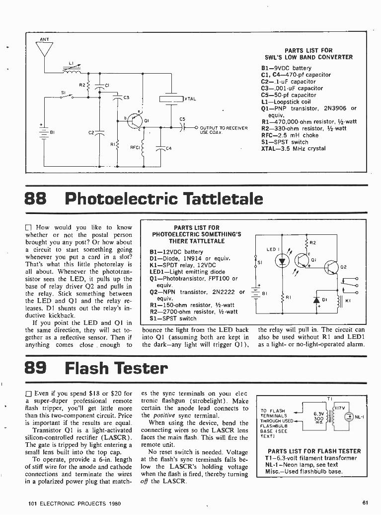
ANT
O OUTPUT TO RECEIVER USE COAX
PARTS LIST FOR SWL'S LOW BAND CONVERTER
B1 -9VDC battery Cl, C4- 470 -pf capacitor C2 -.1 -uF capacitor C3- .001 -uF capacitor C5 -50 -pf capacitor L1- Loopstick coil Q1 -PNP transistor, 2N3906 or
equiv. R1- 470,000 -ohm resistor, 1/2 -watt R2- 330 -ohm resistor, 1/2 -watt RFC -2.5 mH choke Sl-SPST switch XTAL -3.5 MHz crystal
88 Photoelectric Tattletale How would you like to know
whether or not the postal person brought you any post? Or how about a circuit to start something going whenever you put a card in a slot? That's what this little photorelay is all about. Whenever the phototran- sistor sees the LED, it pulls up the base of relay driver 02 and pulls in the relay. Stick something between the LED and 01 and the relay re- leases. D1 shunts out the relay's in- ductive kickback.
If you point the LED and Q 1 in the same direction, they will act to- gether as a reflective sensor. Then if anything comes close enough to
PARTS LIST FOR PHOTOELECTRIC SOMETHING'S
THERE TATTLETALE
B1 -12VDC battery Dl-Diode, 1N914 or equiv. K1 -SPDT relay, 12VDC LED1 -Light emitting diode Q1- Phototransistor, FPT100 or
equiv. Q2 -NPN transistor, 2N2222 or
equiv. R1- 150 -ohm resistor, 1/2 -watt R2- 2700 -ohm resistor, 1/2 -watt S1 -SPST switch
bounce the light from the LED back into Q1 (assuming both are kept in the dark -any light will trigger Q1 ),
the relay will pull in. The circuit can also be used without RI and LEDI as a light- or no- light- operated alarm.
89 Flash Tester Even if you spend $18 or $20 for
a super -duper professional remote flash tripper, you'll get little more than this two- component circuit. Price is important if the results are equal.
Transistor Q1 is a light- activated silicon- controlled rectifier (LASCR). The gate is tripped by light entering a small lens built into the top cap.
To operate, provide a 6 -in. length of stiff wire for the anode and cathode connections and terminate the wires in a polarized power plug that match-
101 ELECTRONIC PROJECTS 1980
es the sync terminals on youi elec tronic flashgun (strobelight). Make certain the anode lead connects to the positive sync terminal.
When using the device, bend the connecting wires so the LASCR lens faces the main flash. This will fire the remote unit.
No reset switch is needed. Voltage at the flash's sync terminals falls be- low the LASCR's holding voltage when the flash is fired, thereby turning off the LASCR.
TO FLASH J TERMINALS THROUGH USED --. FLASHBULB BASE (SEE TEXT)
6.3V 300
TI
I I
NL-I
PARTS LIST FOR FLASH TESTER T1 -6.3 -volt filament transformer NL -1 -Neon lamp, see text Misc. -Used flashbulb base.
61

90 Sensitive Squelch f J The high sensitivity of this circuit is due to the use of a JFET at Ql. With R2 at just 47K, the high impe- dance input JFET is just loafing along. (If you need more sensitivity, try values up to 10 Megohms for R2). The signal input from a detector or other audio signal or noise source within your circuit is applied through
voltage divider R1 and Cl to the gate of Ql. Q 1 amplifies this signal and passes it through C2 to D1 -D2, which convert it to a DC voltage. This is
used to drive switch Q2 on, with a
delayed turn -off provided by R7 -05. R6 -05 delay turn-on. These delays prevent picket- fencing.
FM squelches are noise operated,
where the more noise there is, the less signal. So an FM squelch must disable with increasing input. In an FM system, Q2 would shunt the audio signal to ground at the first audio stage. An AM system would be designed to enable with increasing input. In an AM system, 02 would be used.
PARTS LIST FOR SENS ITIVE SQUELCH
C1 -33 -pF capacitor C2- .05 -uF capacitor C3- 4.7 -uF capacitor C4 -10 -uF capacitor C5- .22 -uF capacitor D1, D2- Diode, 1N914 or equiv. Q1 -FET (Field Effect Transistor),
2N5458 or equiv. Q2 -NPN transistor, 2N2222 or
equiv. R1- 100,000 -ohm potentiometer R2- 47,000 -ohm resistor, 1/2-watt R3- 12,000 -ohm resistor, 1/2-watt R4- 3300 -ohm resistor, 1/2-watt R5- 3.3- Megohm resistor, 1/2-watt R6, R7 -1000 -ohm resistor, 1/2-
watt
+Vo
SIGNAL INO
RI SQUELCH
LEVEL
VO
CI
C
ol °
R
R
C2
SWITCH OUTPUT
1N914
R4 ,-NC4
`C3
01 = 1N914
R5
R6
b
R7
C5
02 c
91 Pence!! NiCad Charger Packaged in a fancy plastic box, with
clips to handle up to four rechargeable batteries, this simple circuit sells for upwards of $10 in many automotive and hardware stores. In actual fact, it can cost less than $1 for the compo- nents, and will handle up to twelve AA (pencell) size NiCads such as used in CB walkie- talkies. The circuit automati- cally limits the charging current to a
proper value, so you can even recharge just one NiCad at a time, if you must.
The best way to handle the NiCads is to use battery holders such as those sold in many electronic parts stores.
You can get holders that accommodate up to six cells each, and a couple of alligator clip jumpers will allow you to configure the terminals to handle less than six cells per holder. Alternatively,
build a holder from a strip of you can
wood with metal, spring -loaded end terminals.
The lamp maintains the charging cur- rent at approximately 20 -mA, and AA (pencell) Nicads should he charged for about 16- hours.
PARTS LIST FOR PENCELL NiCad CHARGER
01- silicon rectifier rated at 200 PIV @ 0.5 -Amps
I1 -type S -6 6 -watt candelabra lamp
120 vAC
UP TO TWELVE
1.2V NICAD AA CELLS
92 Level Detector There are times when voltages are
allowed to vary widely in a given system, so long as they do not exceed some preset limit. This might happen
62
in speed or temperature controls, for example, or even simple R -C timers.
This circuit is based upon a two - transistor comparator. An input volt-
age (which must not exceed BI in either positive or negative value) at
Q3 is compared to a preset divider R3 -R4 at 02. When the input volt-
101 ELECTRONIC PROJECTS 1980

age equals or exceeds the preset volt- age, Q1 turns on, driving pilot lamp II on. Resistor R I permits the use of a #47 type lamp with a standard 9 volt battery.
PARTS LIST FOR LEVEL DETECTOR
B1 -9VDC battery C1 -.1 -uF capacitor Dl-Diode, 1N914 or equiv. I1 -Bulb, #47 -type Q1 -NPN transistor, 2N2222 or
equiv. Q2, Q3 -PNP transistor, 2N3906
or equiv. R1 -27 -ohm resistor, 1/2-watt R2- 5600 -ohm resistor, 1/2-watt R3- 100,000 -ohm resistor, 1/2 -watt
s
BI
RI
II
DI I
02 b
R2
IR 4 LEVEL 03
R5
R3
R6
CI
R4- 1- Megohm potentiometer R5- 3300 -ohm resistor, 1/2 -watt
INPUT o
R6- 1000 -ohm resistor, 1/2-watt Sl-SPST switch
93 Wet Basement Alarm For those of us with basements
plagued by dampness, an early warn- ing of wetness is our best, first line of defense. This tiny circuit monitors for wetness between its two metal probes. When it senses the wet, it pulls in relay K I.
Relay K 1 can be connected to buzzers, bells, pumps, whatever your situation demands. Just make sure the relay contacts are rated for the load you wish to use.
Where actual liquids are to be sensed, the probes can be simple metal spikes driven into the most moisture -prone section of the base- ment floor. To monitor for dampness, etch or scrape a zigzag pattern
PARTS LIST FOR WET BASEMENT ALARM
B1 -12VDC battery Dl-Diode, 1N914 or equiv. K1 -SPDT relay, 12VDC Q1 -NPN transistor, 2N3904 or
equiv. R1- 2700 -ohm resistor, 1/2 -watt Sl-SPST switch
through the middle of a blank cop- per- coated pc board and connect to each isolated area. Position the hoard along the floor or wall you wish to monitor.
SI
94 Automobile Ignition Maze
Install a combination lock on your car's dashboard and a thief would have a better chance playing Russian roulette.
Switches S1 through S5 are spdt rather than spst only to keep all ex- ternal switch markings the same.
Tracing the circuit will show that only if switches S2 and S4 are down is the siren disabled. The siren sounds if any other switch is down or if S2
101 ELECTRONIC PROJECTS 1980
or S4 is up when the ignition is
turned on. A simple wiring change lets you set any combination.
The switches can be "sporty" auto accessory switches sold individually or in switch banks such as G.C. 35- 916. Provide labels such as "Car- buretor Heater," "Window Washer," etc. and no one will know the car is wired for "sound."
63

95 AC Adaptor It seems that just about everything
these days is battery powered, and when something goes bad and you're ready to check it out more than like- ly the size batteries needed are not in your stock, and it's two hours past store -closing time. But with this uni- versal AC adaptor you can handle just about any battery powered repair job that gets on your test bench. Pro- viding up to 300 mA, you can ar- range the output leads of the adaptor to deliver the required polarity con- nections.
Keep in mind, however, that this AC adaptor is for radios, cassette re- corders, and the like. It is not for calculators. Some calculators require
an adaptor with an AC output (the rectifier and filter are in the calcu- lator) and this fact isn't indicated anywhere in the instruction manual or on the calculator. Connect an adaptor with a DC output to a calculator re- quiring an AC input and you prob- ably will be buying a new calculator. So don't claim later you weren't warned.
PARTS LIST FOR AC ADAPTOR T1- Adaptor transformer, Calectro
D1 -743 D1 -D4 -Any silicon rectifier rated
at least 25 PIV at 0.5 A. C1- 2000 -uF, 15 VDC capacitor S1 -Any switch that can provide
4PST.
TI
117 VAC
DI
D3
D2
D4 1 CI
4,5,6,7 OR 9 VDC
n300 MA l 96 Slide Show Stopper
Soundless slide shows are dull, dull, dull! But a stereo recorder can automate the whole show so slides change automatically in step with the commentary.
Record your commentary on the left track. At the instant you want slides to change, record a one -second noise or tone burst on the right track. Connect the programmer between the recorder's right speaker output and the projector's remote control cable. Make a test run to determine the right -track volume setting to make noise or tone bursts activate relay K1. No fancy tone generators needed here. Just give a hearty Bronx cheer into the mike of the left channel only!
Then start the tape from the begin- ning. The audience will hear your commentarys or spectacular music - and -sound reproduction through a speaker connected to the recorder's left channel, while the signal on the right channel automatically changes the slides.
TO
RECORDER SPEAKER OUTPUT
Ti
Di
PARTS LIST FOR SLIDE SHOW STOPPER
C1- 25 -uF, 50 -VDC electrolytic capacitor
D1, D2 -1 -A 400 -PIV silicon rectifier, Motorola 1N4004
K1- 2500 -ohm coil plate -type relay
T1- 5000 -ohm CT audio output transformer
TO
I
PROJECTOR pCONTROL
KI
97 LED Telephone Ring Indicator Know what makes your phone
ring? A 20 Hertz AC signal at any- where from 60 to 120 Volts, depend- ing on your phone company. That same bell- ringing signal can be used to light an LED with the circuit shown here, without significantly loading the telephone line. Cl pro- vides DC isolation to help foolproof this project. The .1 value shown
works, but you may want to increase it to .5 microfarads. Use a mylar capacitor (like the Sprague "Orange Drop" series) rated at 250 -450 work- ing volts or more.
Why so high? The telephone com- pany keeps its lines clear of ice and trouble by daily sweeping a pulse of high voltage throughout the system. Too low a working voltage could
mean trouble for them, and that is absolutely the last thing you want to cause. We might even suggest con- necting to the telephone lines only temporarily to verify circuit opera- tion. This will help avoid accidents and trouble. D 1 through D4 act as a full wave bridge to deliver the AC ringing voltage as DC to LEDI. RI limits the current through the circuit.
64 101 ELECTRONIC PROJECTS 1980

PARTS LIST FOR LED TELEPHONE RING
INDICATOR
C1 -.1 -uF capacitor D1, D2, D3, D4- Diode. 1N914 or
equiv. LED1 -Light emitting diode R1- 82,000 -ohm resistor, 1/2-watt
98 Tone Control Network Since there are no active devices
in this circuit, like transistors or ICs, it can provide no amplification on its own to offset the very lossy character- istics of these networks. Fortunately. most audio systems have more than enough oomph to accommodate this network loss.
Once you have learned, by experi-
menting with the effects of various component values, just how you can alter the characteristics of these net- works, you may want to construct your own graphic equalizer. Just in- clude more stages similar to the two basic types of filters you see here: R1, R2, R3, R4, Cl, C2 and C3 form one of the filters, the rest of the compo-
nents the other. Just remember, the more stages of passive filtering you add, the more loss you introduce into your system. For that reason, most commercial graphic equalizers include built -in amplifiers. And, of course, you will have to duplicate your fil- ter(s) for each channel if you're working in four or more tracks.
INPUT FROM PREAMP OUTPUT TO POWER AMP PARTS LIST FOR
TONE CONTROL NETWORK
C1, C5- .068 -.2 -uF capacitors C2- .033 - .068 -uF capacitor C3- .33- .68 -uF capacitor C4- .005- .02 -uF capacitor R1, R4, R5- 1500 -ohm resistors,
1/2-watt R2, R6- 50,000- 200,000 -ohm po-
tentiometer, logarithmic or audio 'taper
R3, R7-820-1500-ohm resistors, 1/2 -watt
99 Remote Flash Trigger Even if you spend $18 or $20 for
a super -duper professional remote flash tripper, you'll get little more than this two -component circuit. Price is important if the results are equal.
Transistor Q1 is a light- activated silicon -controlled rectifier (LASCR). The gate is tripped by light entering a
small lens built into the top cap. To operate, provide a 6 -in. length
of stiff wire for the anode and cathode connections and terminate the wires in a polarized power plug that match-
101 ELECTRONIC PROJECTS 1980
es the sync terminals on your elec- tronic flashgun (strobelight). Make certain the anode lead connects to the positive sync terminal.
When using the device, bend the connecting wires so the LASCR lens faces the main flash. This will fire the remote unit.
No reset switch is needed. Voltage at the flash's sync terminals falls be- low the LASCR's holding voltage when the flash is fired, thereby turning off the LASCR.
PARTS LIST FOR REMOTE FLASH TRIGGER
Q1 -200 -V light-activated silicon - controlled rectifier (LASCR)
R1- 47,000 -ohm, 1/2-watt resistor
RI
TO SYNC TERMINALS
65

100 Signal- Operated Switch Li If a VOX is a voice operated switch, is this signal operated switch a SOX?
You can take a signal, like the ear- phone jack output from a radio or tape player. and use it to trigger the relay operation. If used with an FM wireless mike, an FM radio and a
cassette recorder, for example, this circuit could start the recorder when- ever the FM radio receives the wire- less mike signal. D1 -R1 -C1 forni an R -C delay network that delays the turn -off of the relay until some time (the number of seconds of delay is
roughly the number of ohms of R1 times the number of microfarads of Cl divided by a million) after the signal stops.
The signal charges Cl through D1, which keeps it from discharging back through the signal source. Cl then holds the base of Ql high until it dis-
PARTS LIST FOR SIGNAL OPERATED SWITCH
B1 -6 -1 VDC C1-2.2-150-uF capacitor D1- Silicon diode (1N914 or
equiv.) K1- Small, sensitive relay (reed re-
lays are ideal); voltage compati- ble with B1; coil impedance greater than B1 voltage by Q1 collector current rating
Q1 -NPN switching transistor; col- lector current rating greater than relay current (2N2222 handles 800 mA and most small relays)
R1- 4700. 470,000 -ohm resistor, 1/2 -watt
charges enough through R1 and the base- emitter circuit of Q1 to reach a turn -off point. Q1 completes the cir- cuit for K l's coil, and you can do
whatever you want with the contacts (turn on a light, start a motor, honk a horn, fire up a computer, light up your TV).
101 Remote Thermometer L With this electronic thermometer you can he sitting by a nice, cozy fire and reading the temperature outdoors, however frigid it may he, without ever catching a chill yourself. The circuit is
a simple one based on a readily avail- able Fenwal thermistor ( Burstein -Ap- plebee. among others. sells them ). For the sake of accuracy, only thermistor R1 should he exposed to temperature extremes; the rest of the components should he kept indoors in an environ- ment where the temperature is reason- ably constant.
To calibrate. you'll need a ther- mometer of known accuracy and ac- cess to temperatures near 0° and 100° F, the lower and upper limits respec- tively of this thermometer's range. Set R4 and R6 to their midpoints. Subject R1 to the hot temperature and adjust R4 until M 1 reads the correct temper- ature. Now subject RI to the cold temperature and adjust R6 to get the right reading on MI . Because the two adjustments interact, repeat the entire procedure two more times.
RI
PART) LIST FOR REMOTE THERMOMETER
R1- thermistor rated 1,000 -ohms @ 25° C (Fenwal part #JB31J1)
R2, R3- 1,800 -ohms R4- 10,000 -ohm trimmer potenti-
ometer R5- 12,000 -ohms R6 -5,000 -ohm trimmer potenti-
ometer R7- 3,900 -ohms R8- 820 -ohms S1 -SPST toggle switch
B1 -9 -volt transistor battery C1- 50 -uF, 16 -VDC electrolytic
capacitor D1-1N746A, 3.3 -volt, 1/2 -watt
zener diode M1 -0 to 100 microamp DC am-
meter
Note: All resistors rated 1/2 -watt, 5% tolerance unless otherwise noted.
66 101 ELECTRONIC PROJECTS 1980

40 INTEGRATED CIRCUIT PROJECTS
I . The CMOS Robot Ear [] The CMOS chip type 4047 provides a convenient monostable and astable multivibrator circuit in one pack- age, with provisions for either positive or negative -going outputs. A high impedance microphone is boosted via one (or more) stage of gain from a 4009 or 4049 hex inverter section. External R and C components determine the on -time. For RI = I megohm and Cl = 1 -uF, the delay interval is 3 seconds. A sensitivity control can be incorporated at the trigger input. The Robot Ear can act as an intrusion detector, voice- operated transmitter switch, or as an automated baby sitter.
PARTS LIST FOR THE ROBOT EAR C1 -1 -uF electrolytic capacitor, 25 VDC (see text) C2- .01 -uF ceramic capacitor, 15 VDC C3- 0.1 -uF ceramic capacitor, 15 VDC 01-small LED IC1 -4047 multivibrator IC2 -4009 or 4049 hex buffer Q1- 2N4401 R1- 1,000,000 -ohm, 1/2 -watt resistor (see text)
12 IO 9 8 7
14 ICI 6
1 2 3 4 5
RI
R3
R2- 1,000,000 -ohm, 1/2 -watt resistor R3- 1,000,000 linear -taper potentiometer R4 -1,000 -ohm, 1/2 -watt resistor
2. Slot Car Race Referee Build this optoelectronic judge and end forever those
quarrels over who really won the race. Install photo - transistors Q1 and 03 at the finish line, but in separate lanes of your slot -car track so that the light- sensitive face of each device is facing upwards. The best method would be to cut a small hole into the track for each phototransistor, and mount each unit flush with the track's surface. Arrange for light to fall on both Q1 and Q3; a small desklamp will work well, but ambient room light will usually suffice. Press SI and both LEDs will go off. The first car to cross the finish line interrupts the light beam and causes the appropriate LED to light up.
PARTS LIST FOR SLOT CAR RACE REFEREE C1- 0.1 -uF ceramic disc capacitor, 35 VDC IC1 -7474 dual D -type flip -flop LED1, LED2- light- emitting diode al, Q3 -FPT -100 NPN phototransistor Q2, Q4- 2N3904 NPN tranistor R1, R2 -18K -ohm 1/2-watt resistor, 10% R3 -3900 -ohm 1/2 -watt resistor, 10% R4, R5- 330 -ohm 1/2-watt resistor, 10% Si- normally open SPST pushbutton switch
5V
LED LANE B
LANE A R4 .w
NOTE NO CONNECTION TO BASE LEAD OF 01 AND 03
¡Ii LED 2 LANE B
101 ELECTRONIC PROJECTS 1980 67

3 IC Audible Logic Probe L] Here is the old familiar logic probe but with a new twist. Instead of displaying logic status with LEDs, it does the job aurally. The logic -I state, 2 -volts or greater, is signalled by a high tone. On the other hand, a low tone sounds to indicate the logic -0 state, 0.8 -volt or less. Inputs between 0.8 and 2 -volts produce no output. (Note that this probe is designed especially for TTL and cannot be used for any other logic family.) The circuit requires a regulated 5 -volt supply, which means that it can be powered by the same supply used by the TTL circuitry under test. Output can he taken from a miniature speaker, as shown in the schematic, or you may use a miniature earphone. Potentiometer R 1 l sets the output volume level.
PARTS LIST FOR IC AUDIBLE LOGIC PROBE C1- 0.1 -uF ceramic disc capacitor, 35 VDC C2- 0.005 -uF mylar capacitor, 35 VDC C3- 0.1 -uF mylar capacitor, 35 VDC C4- 1.0 -uF tantalum capacitor, 10 VDC CL1- alligator clip D1, D2- 1N4001 diode D3, D4 -1N914 diode IC1 -LM339 quad comparator P1 -metal probe tip R1 -10K -ohm 1/2-watt resistor, 10% R2, R3 -220K -ohm 1/2-watt resistor, 10% R4 -30K -ohm 1/ -watt resistor, 5% R5 -12K -ohm '/s -watt resistor, 5% R6- 8200 -ohm 1/2-watt resistor, 5%
TI' +5V
SPKR
CLI
5
4
7
6
+
ICIu
Icl R7
3 -
NC
14
ICIb
R
1 RB
D3* - _C2
2
Tc3
04
0
+
ICIc
RIO
R7, R8, R10 -56K- ohm 1/2 -watt resistor, 10% R9 -120K -ohm 1/2-watt resistor, 10% R11- 1000 -ohm audio -taper potentiometer SPKR -8 -ohm miniature speaker T1- miniature audio output transformer -1,000 -ohm
primary/8-ohm secondary
4. Super Stethoscope Li Auscultation is the medical term for the procedure. In simple language, it means having your ribs ticked with an icy cold stethoscope. Should you ever get the urge to play doctor, we prescribe the simple electronic stetho- scope diagrammed here. Best results will be obtained using hi -fi or communications -type low -impedance head- phones designed to isolate the listener from ambient sounds. Be sure to connect the microphone cartridge to
SHIELDED CABLE
,t, CI
+9v -9V
=C2
7
=C3
PHI MICI "r R
ICI TI
the rest of the circuit using shielded audio cable to keep noise pickup to a minimum. Potentiometer R3 adjusts the gain. Use a socket when mounting ICI since it has delicate FET inputs.
I
R2
R4
-iI C4
R3
PARTS LIST FOR SUPER STETHOSCOPE C1- 0.01 -uF mylar capacitor, 35 VDC C2, C3- 0.1 -uF ceramic disc capacitor, 35 VDC C4 -10 -pF polystyrene capacitor, 35 VDC 41, R4- 1- Megohm, 1/2-watt resistor, 10% IC1 -RCA CA3140 op amp R2- 1000 -ohm, 1/2-watt resistor, 10% MIC1- crystal microphone cartridge R3 -10K linear -taper potentiometer PH1 -low- impedance headphones, hi -fi or communications T1- miniature audio output transformer -1,00 -ohm
type primary, 8 -ohm secondary
68 101 ELECTRONIC PROJECTS 1980

5. Variable Regulated Power Supply 7 These are lots of good power supplies on the market,
but why not build your own and save a bundle? This circuit can provide voltages between 5 and 15 -volts DC at currents up to one ampere. Be sure to heat -sink the iA78GKC regulator by bolting it to either a commercial aluminum heat sink or to your supply's cabinet (if it's made of aluminum). Mount C2 and C3 as close as pos- sible to pins 2 and 4 of ICI. If you cannot locate a
28VCT transformer, go to something slightly higher, say 32 VCT. The same goes for the transformer's current rating; for example, you could use a 2 -amp device.
PARTS LIST FOR VARIABLE REGULATED POWER SUPPLY
BP1, BP2- binding post C1- 2200 -uF electrolytic capacitor, 40 VDC C2- 0.1 -uF ceramic disc capacitor, 35 VDC C3- 100 -uF electrolytic capacitor, 25 VDC D1, D2- 1N4003 (1A, 200 PIV) rectifier diode
ICI pA78GKC `- ' CASE IN CONTACT
WITH PIN 4
FLAT
F1 -0.5- Ampere slow -blow fuse IC1- yA78GKC adjustable voltage regulator M1- 0 -to -1 Amp DC meter M2- 0 -to -15 -Volt DC meter R1 -10K -ohm linear -taper potentiometer R2- 4700 -ohm, 1/2 -watt resistor, 5% S1 -SPST toggle switch T1- 28VCT, 1.2 -Amp power transformer (see text)
6. Jogging Pacesetter One of the problems faced by the beginning jogger,
especially on city streets, is that of maintaining a con- stant pace. Tractor -trailer trucks, careening cars, and ill - mannered dogs can all interrupt your concentration. While there is little that can be done about these nuisances, this little pacesetter may make Them less severe. A miniature earphone in your ear driven by a 555 timer produces regularly spaced "ticks" just like a metronome. The pace can be adjusted via R3 from a leisurely one stride per second to a sole -blistering six paces per second. The whole circuit complete with a 9 -volt transistor radio bat - tery weighs only a few ounces.
PARTS LIST FOR JOGGING PACESETTER C1- 100 -uF electrolytic capacitor, 16 VDC
C2- 0.1 -uF ceramic disc capacitor, 35 VDC
C3- 1.0 -uF tantalum electrolytic capacitor, 20 VDC
IC1 -555 timer PH1 -8 -ohm miniature earphone
RI
R1 -10K, 1/2-watt resistor, 5% R2 -220K, 1/2-watt resistor, 5% R3- 1- Megohm trimmer potentiometer T1- miniature audio output transformer -1,000 -ohm
primary 8 -ohm secondary
7. Sobriety Tester It's a curious and unfortunate fact, but many people
feel that a drink or two will improve their reflexes. Here's your chance to prove them wrong. Imagine for the mo- ment that SI is depressed (open circuited), S2 is closed, and C2 has been completely discharged. On command from someone acting as the tester, the person depressing
SI must remove his hand from that switch and use the same hand to open toggle switch S2. When SI is released, charging current begins to flow into capacitor C2 through RI and R2. This current is interrupted, however, as soon as S2 has been opened. C2 will have accummulated a voltage directly proportional to the reaction time, which
101 ELECTRONIC PROJECTS 1980 71

is the interval between S1's release and the opening of S2. Longer times create higher voltages and cause higher - numbred LEDs to light. For example, a sober person might react quickly enough to light LED 2 or LED 3,
while someone truly sloshed will light up LED 10. To run another test, discharge C2 with S3, then press S1 and, finally, close S2 once more. R 1 should be adjusted so that a sober person lights one of the low- numbered LEDs.
PARTS LIST FOR SOBRIETY TESTER C1- 250 -uF electrolytic capacitor, 35 VDC C2 -50 -uF electrolytic capacitor, 35 VDC IC1- LM3914 LED display driver LED1 through LED10- light- emitting diode R1 -50K trimmer potentiometer R2- 5600 -ohm V2-watt resistor, 10% R3 -33K -ohm 1/2-watt resistor, 10% R4 -47 -ohm 1/2-watt resistor, 10% R5- 1800 -ohm 1/2-watt resistor, 10% R6- 1000 -ohm 1/2-watt resistor, 10% S1- normally closed SPST pushbutton switch S2 -SPST toggle switch S3- normally open SPST pushbutton switch
+18V
8. Top Octave Divider One of the most difficult tasks in electronic music is
generating a perfect, equally -tempered octave. The reason for the difficulty stems from the fact that each note of an octave is related in frequency to the previous note by an unwieldy factor, the twelfth root of 2 (1.059...). This relationship cannot he generated exactly with digital cir- cuits, but using the MK50240P, you can generate such an excellent approximation that nobody will ever notice the difference. Here the 50240 is being clocked by a 1 mHz CMOS oscillator, ICI, which you can tune with R1 until the outputs are on the button (a frequency counter is helpful). Outputs are 15 -volt square waves that can be used as is or divided with flip -flops to yield the lower octaves. IC2 costs about $13, so be sure to use an IC socket to protect your investment.
PARTS LIST FOR TOP- OCTAVE DIVIDER C1 -30 -pF polystyrene capacitor, 35 VDC C2- 0.1 -uF ceramic disc capacitor, 35 VDC IC1 -4047 CMOS multivibrator IC2 -Mostek MK50240P top- octave generator
CI {-- RI R2
i
+15V
i c2
I
2
3
4 Ici
14
13
12
I
10
9- 8-
I
2
3
4
5 I C2
16
15
14
13
12
11
10
9
--007
-1 -oC8
- r- 87
C#70 NC
NC
D#7v
07
--0 A#7
A7
-0 G# 7
E7o-- --0G7 -aF #7 =
F7o
R1 -10K trimmer potentiometer R2 -10K -ohms 1/2-watt resistor, 10%
9. The Waveshaper This little circuit illustrates the principle behind multi -
kilobuck laboratory-style waveform synthesizers as well as some of the more advanced music synthesizers. Into J1 you should feed a square -wave signal swinging from ground to almost 5- volts. The input signal's frequency should be ten times that of the desired output. Adjusting potentiometers R1 through RIO will enable you to literally design the shape of the output waveform. If you can get
hold of an oscilloscope, use it to observe the effect of R1 through R10 on the output. At the same time, feed the output to an audio amp so that you can hear the changes in timbre that occur as the waveshape is altered. Capaci- tor C5 can be used to smooth out the chunky shape of the output. With a 10 kHz input, start with a value of 0.1 µF for C5 and experiment. Make sure at least one poten- tiometer is set to maximum resistance and that at least
72 101 ELECTRONIC PROJECTS 1980

one is set to minimum. This guarantees a full 1 -volt peak -to -peak output. You might also try feeding some interesting waveforms into the Musical Modulator (else- where in this issue) and listening to the notes formed.
PARTS LIST FOR THE WAVESHAPER Cl, C2, C3- 0.01 -uF ceramic disc capacitor, 35 VDC C4- 0.5 -uF mylar capacitor, 35 VDC C5 -see text IC1 -4017 CMOS decade counter IC2 -741 op amp J1, J2 -phono jack R1 through R10- 2- megohm linear -taper potentiometer R11 through R20 -68K -ohm 1/2 -watt resistor, 10% R21, R22 -15K -ohm 1/2 -watt resistor, 10%
RI
R2
R3
R4
R5
R6
R7
I 16
2 15
3 14
4 13
ICI 12
6 II
7 10
8 9
+5V
Ta
-NC 14L3
TYPICAL OUTPUT WAVEFORM
5V o
RI\
INPUT
R8
R9 +5V
RIO =C2
7
tC2
- 5V
=C3
4
R22 C4 D p T
C5 (OPTIONAL )
NOTE OUTPUT FREQUENCY INPUT FREQUENCY -10
10. Electrolytic Capacitor Tester
Here's a quick and simple way to check out all those old electrolytic capacitors in your junkbox. Besides this simple 555 timer circuit, you will need a timepiece with a readout in seconds; the readout may be digital or just an ordinary sweep -second hand. Connect the capacitor to be tested to the binding posts, being careful to observe proper polarities. Now, press S2 and note how long LED 1 stays lit. Multiply the time by the appropriate scale factor to obtain the capacitance. For example, suppose you happen to he checking a very large filter capacitor, which would require that scale C, 100 AF/sec, be used. If the LED remains lit for 67 seconds, the capacitance is 67 X 100 or 6700 microfarads.
PARTS LIST FOR ELECTROLYTIC CAPACITOR TESTER BP1, BP2- binding post Cl, C3- 0.1 -uF ceramic disc capacitor, 35 VDC
C2- 100 -uF electrolytic capacitor, 16 VDC IC1 -555 timer LED1- light- emitting diode R1 -100K -ohm 1/2 -watt resistor, 10%
+9V TIME SCALE TABLE
Range
A
B
C
Scale
1 µF !second 10 AF /second
100 AF /second
BPI I+ TCAPACITOR
-tíì -I UNDER
BP2 TEST
R2- 560 -ohm V2 -watt resistor, 10% R3 -910K -ohm 1/2 -watt resistor, 10% R4-91K-ohm 1/2-watt resistor, 10% R5- 9100 -ohm 1/2 -watt resistor, 10% S1- single -pole, 3- position rotary switch S2- normally open SPST pushbutton switch
I . SST Function Generator This may well be the world's simplest function gen-
erator. You can choose from sinusoidal, triangular or square output waveforms using SI. With S2, any one of 5 frequency ranges, each a decade wide, can be selected, thereby giving complete coverage of everything from a
101 ELECTRONIC PROJECTS 1980
slowpoke 1 Hz to a whizzing 100 kHz. Also, the output level can be varied with RI. Square waveforms will have the highest maximum amplitudes, followed by triangles and sines. The necessary 18 -volts can be obtained from two 9 -volt transistor batteries in series.
73

PARTS LIST FOR SST FUNCTION GENERATOR Cl, C2- 100 -uF electrolytic capacitor, 35 VDC C3, C4- 0.1 -uF ceramic disc capacitor, 35 VDC C5- 0.001 -uF polystyrene or mylar capacitor, 35 VDC C6- 0.01 -uF polystyrene or mylar capacitor, 35 VDC C7- 0.1 -uF mylar capacitor, 35 VDC C8- 1.0 -uF mylar capacitor (non -polarized), 35 VDC C9 -10 -uF tantalum electrolytic capacitor, 35 VDC IC1- Intersil 8038 function generator il-phono jack Q1- 2N3904 NPN transistor R1 -5K linear -taper potentiometer R2, R3- 300 -ohm 1/2-watt resistor, 10% R4 -18K -ohm 1/2-watt resistor, 10% R5- 1000 -ohm 1/2-watt resistor, 10% R6 -10K linear -taper potentiometer R7 -24K -ohm 1/2-watt resistor, 10% S1- single -pole, 3- position rotary switch S2- single -pole, 5- position rotary switch
FREQUENCY RANGE
SELECTION TABLE
Range Frequencies
A 1 to 10 Hz
6 10 to 100 Hz
C 100 to 1 kHz
D 1 kHz to 10 kHz
E 10 kHz to 100 kHz
12. Plant Moisture Meter Talked to your houseplants recently? Well, if they
could talk back, you'd hear plenty of complaints -most of them about water. Too much of the wet stuff is just as bad as too little. To assist you with the watering, try this little moisture meter. Note that you will need to construct a probe assembly consisting of two metal spikes mounted in a wooden or plastic block. For the sake of uniformity, use the dimensions supplied. The spike can be nails or pieces of heavy wire ( #8). Stick the probe as- sembly into the soil surrounding a just -watered plant and adjust R5 for a deflection around mid -scale on Ml. Thereafter you can use the meter to tell whether your plants are too wet or too dry. Note that different plants are apt to prefer different degrees of wetness.
PARTS LIST FOR PLANT MOISTURE METER Cl, C2- 0.01 -uF ceramic disc capacitor, 35 VDC 01, D2 -1N914 diode IC1 -741 op amp M1-0-1 mA DC meter R1- 6800 -ohm 112-watt resistor, 10%
9V. -9v.
=c2
R6
PLASTIC INSULATOR
METAL SPIKE
R2 -15K -ohm 1/2-watt resistor, 10% R3- 1000 -ohm 1/2-watt resistor, 10% R4 -10K -ohm 1/2-watt resistor, 10% R5 -100K trimmer potentiometer R6- 3300 -ohms 1/2-watt resistor, 10%
R5 0-I mA
13. Random Sequence Generator A pseudo- random sequence generator is like a scrambled
counter. Instead of counting 1,2,3,4, ... , the PRSG might yield an output of 2,9,7,1 ... The PRSG shown here sup- plies a sequence of 255 scrambled numbers, available in binary form at the eight outputs (Q 1 through Q8) . Some applications:
First, you might hook up an LED and a 330 -ohm resistor to each output as illustrated. Use a 5 -AF electro-
lytic capacitor for C3, and you'll have a dandy idiot box, which will blink impressively on your desk, but do nothing.
Or, you could hook up the resistor network diagram- med, and use a 330 pF polystyrene capacitor for C3. You'll get a 1 -volt peak -to -peak noise voltage at JI which can be used to generate interesting pet .:ussive sounds in conjunction with the Musical Modulator presented else- where in this issue.
74 101 ELECTRONIC PROJECTS 1980
1116

PARTS LIST FOR PSEUDO -RANDOM SEQUENCE GENERATOR
C1- 0.1 -uF ceramic disc capacitor, 35 VDC C2, C5- 100 -uF electrolytic capacitor, 10 VDC C3 -5 -uF, 10V electrolytic or 330 -pF polystyrene capacitor
(see text) C4- 1.0 -uF mylar capacitor (non -polarized), 35 VDC IC1 -555 timer IC2 -74164 shift register IC3 -7486 quad EX -OR gate J1 -phono jack LED1 through LED8- light- emitting diode R1, R2- 6800 -ohms R3 -100K linear -taper potentiometer R4, R6 -1000 -ohms R5a through R5h- 330 -ohm 1/2-watt resistor, 10% R7- 2200 -ohm 1/2 -watt resistor, 10% R8- 3900 -ohm 1/2 -watt resistor, 10% R9- 8200 -ohm 1/2-watt resistor, 10% R10 -15K -ohm 1/2 -watt resistor, 10% R11 -33K -ohm 1/2 -watt resistor, 10% R12 -62K -ohm 1/2 -watt resistor, 10% R13 -120K -ohm 1/2-watt resistor, 10% R14- 120 -ohm 1/2 -watt resistor, 10%
ICI
RI
6
5 - R2
R3: -4 C3 _
5V
=CI Tc2
I 14 -E 2 13
014-- 3 12
02--4IC2II 034--5 10
04 -- 6 9
8
05 07
06 08
*C. 5uF (IDIOT BOX) OR
330 pf (NOISE)
C5
T
R4
+5V
I 14
2 13
3 12
4 IC311 5 10
6 9
R50-h LEDI ANY 0- - +5V 01 02 03 04 05 06 07 08
1R6!R7 a5V
USE 8 LEDS LIKE JI C4 jR8 jR9 IRI0IRII 1RI21I4
THIS ONE FOR THE --{ I
IDIOT BOX USE RESISTOR NETWORK LIKE THIS TO -z GENERATE NOISE
14. Video Pattern Generator Those of you with oscilloscopes might enjoy bread-
boarding this pattern generator. Feed the signal at JI to your scope's vertical input, and connect the horizontal input to J2. Attach the clips to the selected pairs of test points, then adjust potentiometers R14 and R15 to create complex images. Output signals are about 1 -volt, peak - to -peak.
PARTS LIST FOR VIDEO PATTERN GENERATOR Cl, C2- 250 -uF electrolytic capacitor, 25 VDC C3- 0.1 -uF ceramic disc capacitor, 35 VDC C4, C5- 100 -pF polystyrene capacitor, 35 VDC C6, C7- 1.0 -uF mylar capacitor (non -polarized), 35 VDC C8, C9- 0.5 -uF mylar capacitor, 35 VDC C10- 0.022 -uF mylar capacitor, 35 VDC C11- 0.001 -uF mylar capacitor, 35 VDC CL1, CL2- alligator clip D1 through D8 -1N914 diode IC1- 40248E CMOS ripple divider J1, J2 -phono jack Q1, Q2- 2N3904 NPN transistor R1, R4, R5, R10 -100K -ohm 1/2 -watt resistor, 10% R2, R3- 1.5- Megohm 1/2 -watt resistor, 10% R6, R9 -68K -ohm 1/2 -watt resistor, 10%
+9v>
1cl
C3
9v > Ice
0
DI
R5®ZR6© R7 R8 ® R9 RIO©
=C7 C8 D5! D7 D8
.TT:6.T D2
C6T D3
TRY CONNECTING CLIPS TO THESE PAIRS OF POINTS
B C B B A AC C E D B B F D
2
I 14
2 13
3 12
4 ICI II
5 10
6 9
RI I
CIO
T JI
VERTICAL HORIZONTAL
RIS
R12
R13 ICI
J2
R7, R8 -33K -ohm 1/2 -watt resistor, 10% R11, R12 -47K -ohm 1/2 -watt resistor, 10% R13- 3300 -ohm 1/2 -watt resistor, 10% R14, R15 -250K linear -taper potentiometer
I 5. Featherweight Foghorn i Despite its small size, this circuit generates an au-
thentic- sounding foghorn blast. Couple the output signal to a good amp and loudspeaker, press switch Si, and you'll unleash a blast that will untie the shoelaces of
101 ELECTRONIC PROJECTS 1980 75

anyone within hearing distance. The output signal has a 1 -volt peak -to -peak maximum amplitude, which is just right for driving the AUX or TUNER inputs of most hi -fi or PA amplifiers. You can change the pitch to suit your
own taste by substituting a different value of resistance for R2; larger resistances lower the pitch while smaller ones raise it. Be sure to use a socket with the IC.
PARTS LIST FOR FEATHERWEIGHT FOGHORN Cl, C3- 0.47 -uF mylar capacitor, 35 VDC C2- 0.01 -uF mylar capacitor, 35 VDC C4- 1.0 -uF mylar capacitor, 35 VDC C5- 0.1 -uF ceramic disc capacitor, 35 VDC C6- 100 -uF electrolytic capacitor, 16 VDC IC1- SN76477 sound generator J1 -phono jack R1- 1- Megohm 1/2-watt resistor, 10% R2 -470K -ohm 1/2-watt resistor, 10% R3 -15K -ohm '/e -watt resistor, 10% R4 -10K -ohm 1/2-watt resistor, 10% R5- 1.5- Megohm Vrwatt resistor, 10% R6 -180K -ohm 1/2-watt resistor, 10% R7 -150K -ohm 1/2-watt resistor, 10% R8 -47K -ohm 1/2-watt resistor, 10% R9 -5K audio -taper potentiometer Sl-SPST normally open pushbutton switch
RI
I I >. I
28 27 26 25 24
1 2 3 4 S 6
R3
R2
C2
T
R4
23 22 21 20 19 18 17 16 I
ICI
7 8 9 10 II 12 13 14
RS IC31
I ISI
R6 R8 1
R7
C51 1+ R9 C4 T T C6
JI OUTPUT
< +9V
VOLUME
I6. Active Low Pass Filter As its name suggests, a low -pass filter passes signals
with frequencies lower than some specific value, called the cut -off frequency, but blocks passage of frequencies above the cut -off. Illustrated here is an active low -pass filter having a 1000 Hz cut -off frequency. You can shift the cut -off by changing C I and C2 together. To multiply the cut -off by a factor of N, multiply the capacitances of CI and C2 by a factor of 1 'N. For example, a 2000 Hz cut -off would require 0.005 µF capacitors, while a 500 Hz cut -off calls for 0.02 AF capacitors for Cl and C2. Drive the filter directly from the output of a preced- ing op -amp stage for best results.
PARTS LIST FOR ACTIVE LOW PASS FILTER Cl, C2- 0.01 -uF polystyrene or mylar capacitor, 35 VDC C3, C4- 0.1 -uF ceramic disc capacitor, 35 VDC IC1 -741 op amp J1, J2 -phono jack R1 -12K -ohm 1/2-watt resistor, 5%
JI
C2
+9V. I -9V.
I 3 IC4
R2 -22K -ohm 1/2-watt resistor, 5% R3, R4 -68K -ohm 1/2-watt resistor, 5%
17. Alternator Monitor This circuit will monitor the output of the alternator of
any car with a 12 volt electrical system and indicate if the charging system is either undercharging or overcharg- ing. This is accomplished by using 2 sections of a quad voltage comparator IC and connecting the outputs in an "OR" configuration so that the LED will become lit if section A or section B of the comparator detects an improper voltage level. The circuit is connected into any
circuit which is active when the car is in operation, such as the ignition or radio circuit. This prevents drain on the battery when the car is not in use. To calibrate the cir- cuit, connect an adjustable DC power supply to the + and - inputs of the circuit. Set the power supply to 13.4 volts and adjust R3 so that the voltage at pin 5 of ICIA is maximum. Then adjust R4 so that the LED just goes out. Set the power supply to 15.1 volts and adjust R3 so
76 101 ELECTRONIC PROJECTS 1980
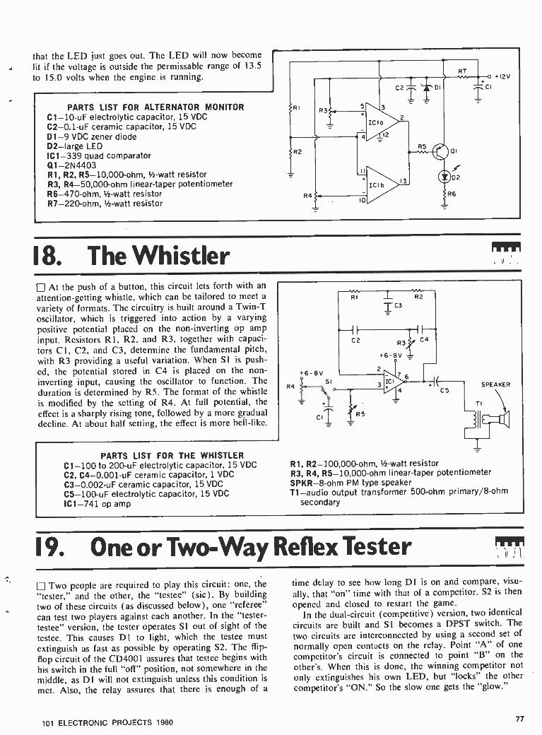
that the LED just goes out. The LED will now become lit if the voltage is outside the permissable range of 13.5 to 15.0 volts when the engine is running.
PARTS LIST FOR ALTERNATOR MONITOR C1 -10 -uF electrolytic capacitor, 15 VDC
C2- 0.1 -uF ceramic capacitor, 15 VDC D1 -9 VDC zener diode D2 -large LED IC1 -339 quad comparator Q1- 2N4403 R1, R2, R5- 10,000 -ohm, l/ -watt resistor R3, R4- 50,000 -ohm linear -taper potentiometer R6- 470 -ohm, 1/2 -watt resistor R7- 220 -ohm, 1/2-watt resistor
.12V
18. The Whistler At the push of a button, this circuit lets forth with an
attention -getting whistle, which can be tailored to meet a
variety of formats. The circuitry is built around a Twin -T oscillator, which is triggered into action by a varying positive potential placed on the non -inverting op amp input. Resistors Rl, R2, and R3, together with capaci- tors Cl, C2, and C3, determine the fundamental pitch, with R3 providing a useful variation. When SI is push- ed, the potential stored in C4 is placed on the non - inverting input, causing the oscillator to function. The duration is determined by R5. The format of the whistle is modified by the setting of R4. At full potential, the effect is a sharply rising tone, followed by a more gradual decline. At about half setting, the effect is more bell -like.
PARTS LIST FOR THE WHISTLER C1 -100 to 200 -uF electrolytic capacitor, 15 VDC
C2, C4- 0.001 -uF ceramic capacitor, 1 VDC C3- 0.002 -uF ceramic capacitor, 15 VDC
C5- 100 -uF electrolytic capacitor, 15 VDC
IC1 -741 op amp
+6 -8V
R4 SI 3 + SPEAKER
CS
R1, R2-100,000-ohm, 1/2-watt resistor R3, R4, R5- 10,000 -ohm linear -taper potentiometer SPKR -8 -ohm PM type speaker T1 -audio output transformer 500-ohm primary/8 -ohm
secondary
9. One or Two-way Reflex Tester
LJ Two people are required to play this circuit: one, the "tester," and the other, the "testee" (sic). By building two of these circuits (as discussed below), one "referee" can test two players against each another. In the "tester - testee" version, the tester operates Si out of sight of the testee. This causes D1 to light, which the testee must extinguish as fast as possible by operating S2. The flip -
flop circuit of the CD4001 assures that testee begins with his switch in the full "off" position, not somewhere in the middle, as DI will not extinguish unless this condition is
met. Also, the relay assures that there is enough of a
time delay to see how long D1 is on and compare, visu-
ally, that "on" time with that of a competitor. S2 is then opened and closed to restart the game.
In the dual- circuit (competitive) version, two identical circuits are built and SI becomes a DPST switch. The
two circuits are interconnected by using a second set of
normally open contacts on the relay. Point "A" of one competitor's circuit is connected to point "B" on the other's. When this is done, the winning competitor not only extinguishes his own LED, but "locks" the other competitor's "ON." So the slow one gets the "glow."
101 ELECTRONIC PROJECTS 1980 77

PARTS LIST FOR REFLEX TESTER D1- 1N4001 diode D2 -small LED IC1 -4001 quad NOR gate Q1- 2N4401 transistor R1, R2- 870,000 -ohm, 1/2-watt resistor R3- 2,000 -ohm, 1/2 -watt resistor R4- 510 -ohm, 1 -watt resistor RL1 -relay w/9 VDC coil; one set normally open con-
tacts, and one set normally closed contacts S1 -SPST toggle switch S2 -SPDT toggle switch
S2
1 14
2 13
3 IC 12
4 II
5 10
6 9
7 8
9VDC
SI
1
NORMALLY OPEN CONTACTS
A 1__,,
e SEE
TEXT
NORMALLY CLOSED CONTACTS
20. Single Supply Signal Shifter Op amps, like the popular 741, are usually operated
with matching plus and minus power supplies. However, for simple signal amplification applications, the single positive supply shown below has been found to work quite nicely. Resistors R3 and R4 may be fixed at about 5000 ohms each, or replaced with a 5K or 10K potentiom-
eter, if it is desired to adjust the no- signal output level so that high -amplitude signals will not he clipped. Sometimes, intentional clipping is desired, so this feature may be re- tained for general experimental applications. Note: If a potentiometer is used for R3, R4, connect center termi- nals of pots to pin #3 of ICI.
PARTS LIST FOR SINGLE SUPPLY SIGNAL SHIFTER C1- 0.01 -uF ceramic capacitor, 15 VDC (gain =10)
-0.10 -uF ceramic capacitor, 15 VDC (gain =100) C2 -1 to 100 -uF electrolytic capacitor, 15 VDC (in-
crease value with frequency) C3- 100 -uF electrolytic capacitor, 15 VDC IC1 -741 op amp R1- 10,000 -ohm, 1/2 watt resistor R2- 100,000 -ohm, V2 watt resistor (gain =10)
-1,000,000 -ohm, 1/z watt resistor (gain =100) R3, R4 -5,000 -ohm, V2 watt resistor or 5,000 -10,000
ohm linear taper potentiometer
CI
°--i
.9V
R3
R4
RI R2
11111 Eill
C2 o
OUTPUT
1
21. Simple RF Generator A single capacitor can turn a TTL hex -inverter into
an RF generator with good solid waveform output. The circuit was checked out on both a 7404 standard TTL chip and the low power Schottky 74LSO4 with about equal results, though slight departures in frequencies must be expected. One or more buffer stages from un- used inverters on the chip may also be utilized.
PARTS LIST FOR SIMPLE RF GENERATOR C1- 0.01 -uF ceramic disc capacitor, 15 VDC IC1 -7404 hex inverter
78 101 ELECTRONIC PROJECTS 1980

22. Pennypincher's Frequency Meter One of the handiest instruments you can own is the
digital frequency counter, but unless you do an awful lot of experimenting, the expense is usually hard to justify. However, if you can spare $15, consider building this analog frequency meter. Input impedance is 100,000 - ohms, and frequencies up to 50 kHz can be measured,
which makes the instrument ideal for the audio experi- menter. After construction, calibrate the instrument by first selecting the middle range (Range B, 0 -5 kHz) with Si. Feed a 5 -kHz signal of known accuracy to JI, and adjust potentiometer R$ for a full -scale deflection on meter M1. That's it.
PARTS LIST FOR PENNY PINCHER'S FREQUENCY METER
Cl, C4, C7- 0.1 -uF ceramic disc capacitor, 35 VDC
C2 -5 -pF polystyrene capacitor, 35 VDC
C3- 100 -pF polystyrene capacitor, 35 VDC
C5, C6- 100 -uF electrolytic capacitor, 10 VDC
C8- 3000 -pF polystyrene capacitor, 35 VDC D1, D2, D3- 1N4001 diode IC1 -LM311 comparator IC2 -555 timer J1 -phono jack M1 -0 -50 microAmp DC meter R1- 4700 -ohm 1/2-watt resistor, 10% R2, R3, R4, R5- -18K -ohm 1/2-watt resistor, 5% R6- 1000 -ohm 1/2-watt resistor, 10% R7 -10K -ohm 1/2-watt resistor, 10% R8 -10K trimmer potentiometer R9, R11 -30K -ohm 1/2-watt resistor, 5% R10 -300K -ohm 1/2-watt resistor, 5% R12- 3000 -ohm 1/2-watt resistor, 5% R13 -10 Megohm 1/2-watt resistor, 10% Sl- single pole, 3- position rotary switch
JI
~ CI
DIX R2 RI
02= R3
RANGE /FREQUENCY
TABLE
Range Frequency
A O to 500 Hz
B O to 5 kHz
C O to 50 kHz
R4 6
R6
C2
D3XR7
I-
C3
R8
i
i 1+ c+5v C4; C5
+
I 8
2 IC2 7^ 3 6-
Tee.
RIO RII R12
I
c7
C SI
TC8
23. Antenna Bearing Indicator Using an economy -type rotator with your TV, FM or
ham beam -type antenna? Then you probably have a
direction indicator that's hard -to -read, inaccurate, or in
the case of homebrew rotators, probably non -existent. However, it's easy to add on a direction indicator using LEDs for readout. Referring to the schematic, note direc- tion- sensing potentiometer R 1. As its wiper moves away from ground potential, first LED 1 will light, then LED 2
will come on as LED 1 extinguishes; this process con- tinues in numerical succession until finally LED 10 is the only lit LED. Coupling the pot to your rotating antenna's shaft with pulleys and a belt allows the display of LEDs to respond to antenna position. The potentiometer's pul- ley should have a larger diameter than that of the an- tenna shaft because most potentiometers cannot rotate through a full 360 °.
PARTS LIST FOR ANTENNA -BEARING INDICATOR C1- 100 -uF electrolytic capacitor, 35 VDC C2 -5 -uF electrolytic capacitor, 10 VDC IC1- LM3914 LED display driver LED1 through LED10- light- emitting diode
+9 TO +18v
ANTENNA -SHAFT PULLEY
POTENTIOMETER PULLEY
R1 -25K linear -taper potentiometer R2- 3900 -ohm, 1/2-watt resistor, 5% R3- 1200 -ohm, 1/2-watt resistor, 5%
101 ELECTRONIC PROJECTS 1980 79

24. Touch -Activated Combination Lock 4*" Here's an electronic combination lock that's tough to
crack. To open the lock, thereby causing relay K1 to pull in and LED 1 to light, you must touch TS1, TS2, TS3 and TS4 in sequence. Should one of the dummy switches, TS5 through TS9, be touched, the lock immediately re- sets and the complete 4 -digit combination must be re- entered to open it. Since there are five dummies, chances
of ever opening the lock accidentally are slim indeed. Once you've opened the lock, just touch one of the dum- mies to lock it again. The touch switches consist of two small pieces of aluminum or copper separated by a %a-inch gap. Bridging the gap with a fingertip closes the switch. If you like, conventional normally open push- buttons could be substituted for the touch switches.
PARTS LIST FOR TOUCH- ACTIVATED COMBINATION LOCK
C1- 0.1 -uF ceramic disc capacitor, 35 VDC C2- 220 -uF electrolytic capacitor, 16 VDC D1 -1N914 diode IC1, IC2 -4013 CMOS dual D -type flip -flop K1 -6V, 500 -ohm relay with SPST contacts LED1- light- emitting diode Q1- 2N3904 NPN transistor R1 through R5 -100K -ohm 1 -watt resistor, 10% R6 through R10 -4.7 Megohm 1 -watt resistor, 10% R11 -18K -ohm 1/2-watt resistor, 10% TS1 through TS9 -touch switches made of 2 pieces
metal separated by a 1/16 -inch gap.
TSI
RI
R6
+9V.
i NC I
T T 1
S- 9 12 13--5 14 21--9
i2 13
ICIb 4 IC2o IC2b bf I 8 7
8
NC NC
T52
R2
R7
R3
T$3
R8
d R4
R9
RII 01
LED I
OPEN / TO
LOAD
--0D-- TS5
TS6 RS D__TS7
RIO 45 _TS8
25. The Optical Oracle In ancient times, if you needed help with a tough deci-
sion you went to the neighborhood oracle who, for a small fee, supplied you with advice straight from the gods. Those days are gone, unfortunately, but if you're really desperate for advice, maybe this circuit will help. Ask the Optical Aracle a question, press and release Si, and read your answer -YES, NO or MAYBE -on the lit LED. You'll get a MAYBE 25% of the time and a definitive YES or NO the rest of the time. If your horse comes in a winner, simply send 10% of the purse to us.
PARTS LIST FOR THE OPTICAL ORACLE C1- 0.1 -uF ceramic disc capacitor, 35 VDC C2- 330 -pF polystyrene capacitor, 35 VDC IC1 -4022 CMOS octal counter IC2 -555 timer LED1, 2, 3- light- emitting diode Q1, Q2, Q3- 2N3904 NPN transistor R1, R2, R3- 680 -ohm 1/2-watt resistor, 10% R4 through R11 -47K -ohm 1 -watt resistor, 10%
9V.
R12- 2200 -ohm 1/2-watt resistor, 10% R13, R14 -18K -ohm 1/2-watt resistor, 10% S1- normally open SPST pushbutton switch
80 101 ELECTRONIC PROJECTS 1980

26. LED Black Jack The object is to see who can gzt closest to 21 LED
flashes without going over. Any number of people can play. Press SI until D2 starts flashing (1 second on, 1
second off). Then count the number of pulses after S1
is released. You may get 5 the first time. That is like being dealt a 5 in Black Jack. Do it again and add the second count to the first, etcetera, until you are as close as you can get to 21 without going over. If you go over, you are out of the game. A fun game and easy to build. The 9 volt battery will last for months.
PARTS LIST FOR LED BLACKJACK C1- 4.7 -uF tantalum capacitor, 15 VDC C2- 0.1 -uF ceramic disc capacitor, 15 VDC D1- 1N4001 diode D2 -small LED IC1 -4000 NOR gate
9V
R1- 5,000,000 -ohm, '/ -watt resistor R2- 30,000 -ohm, 1/2 -watt resistor R3, R4-10,000,000-ohm, 1/2-watt resistor R5- 1,000 -ohm, 1/2 -watt resistor Sl -SPST pushbutton (doorbell) switch
27. The Howler This howler will produce a loud dog -like howl that
starts strong and slowly grows weaker and weaker until it stops. To start it again, just press SI . Useful for alarms, bicycle horns, a different type doorbell, or as a Halloween trick. Changing R4 will change the frequency, or pitch of the howl, but the main purpose of R4 is to set the filter circuit into oscillation with the op amp. Adjust R4 until oscillations begin. The output should go to an amplifier rather than just to a speaker directly because the effect is better.
PARTS LIST FOR THE HOWLER C1, C2- .001 -uF ceramic disc capacitor, 15 VDC C3- .005 -uF ceramic disc capacitor, 15 VDC IC1 -741 op amp R1- 10,000 -ohm, 1/2-watt resistor R2- 1,000,000 -ohm, linear -taper potentiometer
R3, R4- 220,000 -ohm, 1/2 -watt resistor S1 -SPST momentary- contact switch
28. Crystal -Controlled TTL This inexpensive color -TV crystal of approximately
3.58 MHz can readily be persuaded to oscillate in the following 7404 circuit. The resultant waveform can be divided down, via other popular IC chips, such as the 4017 CMOS type.
PARTS LIST FOR CRYSTAL -CONTROLLED TTL C1 -75 -pF mica capacitor, 15 VDC C2- 0.01 -uF ceramic capacitor, 15 VDC IC1 -7404 hex inverter R1- 1,000 -ohm, 1/2 -watt resistor XTAL -3.58 MHz crystal (color TV carrier type)
CI
XTAL
RI - 1
IC 2 3
ICIb ICIc
7 6
9 ICId
ICle
IC f
14
10
G+SVOC
o RF OUT
101 ELECTRONIC PROJECTS 1980 81
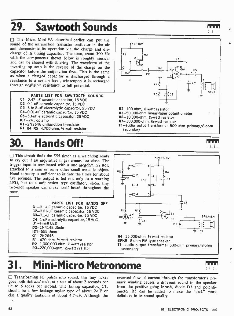
29. Sawtooth Sounds The Micro- Mini -PA described earlier can put the
sound of the unijunction transistor oscillator in the air and demonstrate its operation via the charge and dis- charge of its timing capacitor. The tone, about 300 Hz with the components shown below is roughly musical and can be shaped with filtering. The waveform of the inverting op amp is the reverse of the charge on the capacitor before the unijunction fires. This is the same as when a charged capacitor is discharged through a resistance to a certain level, whereupon it is recharged through negligible resistance to full potential.
PARTS LIST FOR SAW -TOOTH SOUNDS C1- 0.47 -uF ceramic capacitor, 15 VDC C2- 0.1 -uF ceramic capacitor, 15 VDC C3 -6 to 8 -uF electrolytic capacitor, 25 VDC C4- 0.01 -uF ceramic capacitor, 15 VDC C5 -50 -uF electrolytic capacitor, 25 VDC IC1 -741 op amp Q1- 2N2646 unijunction transistor R1, R4, R5- 4,700 -ohm, 1/2 -watt resistor
IL SPKR
R2- 100 -ohm, 1/2-watt resistor R3- 50,000 -ohm linear -taper potentiometer R6- 10,000 -ohm, 1/2 -watt resistor R7- 100,000 -ohm, 1/2-watt resistor T1 -audio outut transformer 500 -ohm primary /8 -ohm
secondary
30. Hands Off! This circuit finds the 555 timer as a watchdog ready
to cry out if an inquisitive finger comes too close. The trigger input is terminated with a one megohm resistor, attached to a coin or some other small metallic object. Hand capacity is sufficient to initiate the timer for about five seconds. The output is fed not only to a warning LED, but to a unijunction type oscillator, whose tiny two -inch speaker can make itself heard throughout the room.
PARTS LIST FOR HANDS OFF C1- 0.1 -uF ceramic capacitor, 15 VDC C2- 0.01 -uF ceramic capacitor, 15 VDC C3- 0.1 -uF ceramic capacitor, 15 VDC C4 -1 -uF electrolytic capacitor, 15 VDC D1 -small LED D2- 1N4148 diode IC1 -555 timer Q1- 2N2646 R1- 470 -ohm, 1/2 -watt resistor R2- 1,000,000 -ohm, 1/2 -watt resistor R3- 220,000 -ohm, 1/2 -watt resistor
'6V TO 8V
R4- 15,000 -ohm, 1/2 -watt resistor SPKR -8 -ohm PM type speaker T1 -audio output transformer 500 -ohm primary /8 -ohm
secondary
31. Mini -Micro Metronome Transforming IC pulses into sound, this tiny ticker
goes both tick and tock, at a rate of about 2 seconds per tic to 6 tocks per second. The timing capacitor, Cl, should be a low leakage mylar type of about 2 -uF or else a quality tantalum of about 4.7 -uF. Although the
reversed flow of current through the transformer's pri- mary winding causes a different sound in the speaker from the positive -going inrush, diode D3 and potenti- ometer RS can be added to make the "tock" more definitive in its sound quality.
82 101 ELECTRONIC PROJECTS 1980

PARTS LIST FOR MINI -MICRO METRONOME C1 -2 to 5 -uF low- leakage mylar or tantalum capacitor,
15 VDC C2 -2.2 to 10 -uF electrolytic capacitor, 15 VDC D1, D2, D3- 1N4148 diode IC1 -4011A quad NAND gate Q1- 2N4401 transistor Q2- 2N4403 transistor R1-47,000-ohm, 1/2 -watt resistor R2, R3- 500,000 -ohm linear -taper potentiometer R4, R6- 10- ohm,1/2 -watt resistor R5- 1,000 -ohm linear -taper potentiometer T1 -audio output transformer 500 -ohm primary /8 -ohm
secondary
TI
SPKR
32. Musical Modulator Feed this circuit a simple audio tone, and it gives you
back a musical note with selectable attack, sustain and decay. Input impedance is 10,000 -ohms, output im- pedance is 1000 -ohms, and the gain is unity. Best results will be obtained with signal inputs having amplitudes of 1 -volt peak -to -peak or less. When SI is pressed, the out- put volume rises at a rate determined by attack control R11. As long as SI is pressed, the sound will be sustained. Releasing SI causes the note to decay at a rate deter- mined by decay control R 10. Try sine, square or trian- gular wave inputs for musical notes. With a noise input you can imitate such things as gunshots and explosions. Trimmer R7 can he adjusted to cancel but any audible "thumping" (noticeable with very rapid attack or decay).
PARTS LIST FOR MUSICAL MODULATOR C1- 0.33 -uF mylar capacitor, 35 VDC C2, C3- 0.1 -uF ceramic disc capacitor, 35 VDC C4- 0.005 -uF mylar capacitor, 35 VDC C5- 2.2 -uF electrolytic capacitor, 16 VDC 01, D2 -1N914 diode ICI -RCA CA3080 transconductance amp J1, J2 -phono jack Q1- 2N3904 NPN transistor R1- 9100 -ohm 1/ -watt resistor, 10%
CI RI JI
INPUT 2
5V -5V
IC2 1C3
J2 1C4 T OUTPUT
R7
R8 DECTAY ATTACK
i -5v
o
R2, R3, R4- 1000 -ohm 1/2-watt resistor, 10% R5 -2.2 Megohm 1/2 -watt resistor, 10% R6 -15K -ohm 1/2 -watt resistor, 10% R7 -1 Megohm trimmer potentiometer R8, R9- 5600 -ohm 1/2 -watt resistor, 10% R10, R11 -250K linear -taper potentiometer S1- normally open SPST pushbutton switch
33. Dividing lt All Up The type 4018 programmable counter is a useful digi-
tal tool, especially where a basic clock frequency must be divided down for various timing operations. With proper con>ections, divisors of from 2 through 10 may be configured. The table shown below gives the connec- tions. The odd divisors do not give symmetrical outputs, but close ratios, such as four -high, three -low for a divide - by -seven setup. Digital -to- Analog Conversion may also be studied by connecting the outputs as shown. Interesting waveforms may he obtained by trying out the various dividing connections, while tying an oscilloscope into
101 ELECTRONIC PROJECTS 1980
the different resistor network junctions. With the circuit set for a divide -by -ten function, a digital sine wave may be discovered at certain points along the network. With clock frequencies above 1 KHz, this output may be heard on an audio amplifier. Computer Music, anyone?
PARTS LIST FOR DIVIDING IT ALL UP IC1 -4018 dividing counter IC2 -4011A quad NAND gate R1 through R6- 100,000 -ohm, 1/2-watt resistor R7 through R10- 47,000 -ohm, 1/2-watt resistor
83

A
To Connect Pins Divide 1&2 of IC2 To
By Pin 1 Pin 2
2 Cl Cl 3 C2 Cl 4 C2 C2 5 C2 C3 6 C3 C3 7 C3 C4 8 C4 C4 9 C4 C5
10 C5 C5
5-10V
C4
-- C5
CLOCK INPUT
16
2
3
7 ICI 8
9
10
12
15
5-<CI 4-{C2 6--(C3
11
13
14
12
13
ñ 4
5 -10V
RI R6
SAMPLE POINTS
DIGITAL TO ANALOG CONVERSION NETWORK
34. The TTL Robot Ear The type 555 timer can not only see, but hear, as this
sound pick -up circuit shows. It is most apt in picking up sudden sharp sounds. A type MPS A 13 Darlington tran- sistor provides gain to cause triggering action. With RC time constants of 4.7 or 5 -uF and 220,000 ohms, the warning indicator LED will remain on for about two seconds.
PARTS LIST FOR THE TTL ROBOT EAR C1- 0.1 -uF ceramic capacitor, 15 VDC C2 -5 -uF electrolytic capacitor, 15 VDC D1 -small LED IC1 -555 timer Q1- Motorola MPS -A13 transistor R1- 47,000 to 100,000 -ohm, 1/2 -watt resistor
6v
.I 8. . 2 7 sow ICI
o 3 MIMI 4 5
R2- 470 -ohm, 1/2 watt resistor R3- 220,000 -ohm, 1/2 -watt resistor
35. Mini -Modern Crystal Receiver A 741 mini -power- amplifier can update those 1N34
"cat's whiskers" crystal receivers right into the Space Age. Depending on antenna and ground facilities, good reception is possible with clear volume from the tiny speaker. A 9 -volt transistor battery provides portable radio convenience for escaping the frustrations of the IC experimental test bench, for one thing!
PARTS LIST FOR MINI -MODERN CRYSTAL SET C1- 365 -pF variable capacitor C2- 0.01 -uF ceramic capacitor, 15 VDC C3- 0.1 -uF ceramic capacitor, 15 VDC C4, C5- 100 -uF electrolytic capacitor, 15 VDC C6 -50- 100 -uF electrolytic capacitor, 15 VDC D1 -1N34 diode IC1 -741 op amp L1- loopstick coil R1- 25,000 -ohm linear -taper potentiometer R2 -25K to 50,000 -ohm audio taper potentiometer
ANTENNA CONNECTION
R6 R3
GROUND CONNECTION
R3- 1,000,000 -ohm, 1/2 -watt resistor R4, R5- 4,700 -ohm, 1/2 -watt resistor R6- 10,000 -ohm, 1/2 -watt resistor T1-500/8-ohm audio output transformer MISC. -8 -ohm 2 in. PM type speaker; snap type 9 V
battery clip
84 101 ELECTRONIC PROJECTS 1980

36. Multi -Input Music Synthesizer PARTS LIST FOR MULTI -INPUT MUSIC SYNTHESIZER IC1 -4016 quad bilateral switch R1 through R5- 1,000 -ohm, 1 -watt resistor S1 through S4 -SPDT slide switch
The inputs to this synthesizer can be from any musical instruments. C4 can be from an electric guitar, C5 from an electronic organ, etc. Or the inputs can be from the outputs of the "Octave Music Maker" project. The volt- age should not exceed 9 volts at these inputs. The output will be a combination of the inputs, where you control the combining via the switches. The switch marked "S1" will put the C4 input through to the output when it is switched to the down position.
C4
C5
C6 0----
C7 o-,
14
2 13
3 ICI 12
4 II
5 10
6 9
9V.--0"473 SI (C4 INPUT)
+9V S2 (C5) O S3(C6) _ a--- 9V
cr-=- 9V.--o` S4 (C7)
9v
OUT
RS 2
37. Mini - Digital Roulette rJ A more adult form of entertainment can be obtained from the 4026 counter and display previously described. The clock input terminal is connected via a pushbutton switch to the "Basic Pulse Maker" and two to nine players select a number. Then, press the button. The input fre-
NOTE: USE ONE DRIVER (OI -7) FOR EACH LED ELEMENT
quency should be 10 -Hz or higher and the Reset may zero the display first, although there is statisticatly little or no effect upon subsequent outcomes. When the switch is released, the counter holds on one number, which is displayed until reset or new counts arrive. If a Zero ap- pears on the display, it may be assumed that the Bank takes all wagers, thus keeping the system in fresh batteries.
NOTE: GROUND PINS 3,5,9,14 OF LED I 6V
FREQUENCY TIME
IC2
RESET 8 PLAY
DI 16]--
15
S1 0
10 } 12 D- B
13]-+ C
9,} D
11D- E
6 F 7} G
1\52
D2
1RESET
R4 1 +6V
01 7
PARTS LIST FOR MINI -DIGITAL ROULETTE
C1 -0.47 to 2.2 -uF electrolytic capacitor, 15 VDC C2- 100 -uF electrolytic capacitor, 15 VDC D1, D2- 1N4148 or 1N914 diode IC1 -4011 quad NAND gate IC2 -4026 decade counter LED 1 -DL -750 7- segment display
Q1 through Q7- 2N4401 transistor R1-500-000-ohm I inear -taper potentiometer R2- 100,000 -ohm linear -taper potentiometer R3- 10,000 -ohm, V2-watt resistor R4 through R11 -1,000 -ohm, 1/2-watt resistor Si, S2 -SPST momentary- contact switch
R5 -II
TO DISPLAY SEGMENTS A- G
OF LED I
101 ELECTRONIC PROJECTS 1980 85

38. Guitar Tuning Aid By taking advantage of the frequency stability of the
555 timer IC operating in an astable mode, an oscillator can be constructed which can be used as a tuning aid for the guitar. The first string of the guitar, E, produces a
note with a frequency of 82.4 Hertz. The frequency of the oscillator is set to twice this value, 164.8 Hertz, and then followed by a divide -by -two stage to produce the desired frequency. The purpose of the divide -by -two stage is to guarantee that the waveform produced has a
duty cycle of exactly 50'", . This produces a note with no second harmonic distortion. The frequency of oscilla- tion of the circuit is set by adjustment of R1, R2, and C2 also determine the frequency of oscillation but these components are fixed values and need no adjustment. The output of IC2 is fed to an emitter follower to pro- vide current gain to drive a loudspeaker. C3 acts as a
low -pass filter to attenuate harmonics and produce a
more natural sounding note. The circuit is powered by
a 5 volt supply, and this voltage must fall within the range of 4.75 to 5.25 volts for IC2 to operate properly.
PARTS LIST FOR GUITAR TUNER
Cl , C4- 0.1 -uF ceramic capacitor, 15 VDC
C2 -15 -uF electrolytic capacitor, 15 VDC
. SV
14 12 9 8 I I
IC2 5
2 6 10
C3- 100 -uF electrolytic capacitor, 15 VDC IC1 -555 timer IC2 -7490 decade counter Q1- 2N4401 R1- 50,000 -ohm linear -taper potentiometer R2, R4- 4,700 -ohm, 1/2-watt resistor R3- 33,000 -ohm, 1h -watt resistor R5 -33 -ohm, 1/2-watt resistor SPKR -8 -ohm PM type speaker
39. Digital Modulator WTI
When a high- frequency oscillator is gated by a much lower frequency, modulation is accomplished. The fol- lowing circuit provides a 1 MHz oscillator modulated or gated by a variable frequency in the audio range. A transistor -buffer is used for the output. The resulting signal can be employed for a variety of AM radio testing and each signal may be individually be taken off, in- creasing the versatility of this little circuit. Note: Do not use an antenna longer than 3 ft., or RF emission may exceed allowable FCC standards and cause illegal RF interference.
PARTS LIST FOR DIGITAL MODULATOR C1- 0.01 -uF ceramic capacitor, 15 VDC C2- 100 -pF mica capacitor, 15 VDC C3- 0.1 -uF to 0.22 -uF ceramic capacitor, 15 VDC IC1 -4011A quad NAND gate
RI
6V
+6V
I' PIN 14
C3 7
Q1- 2N4401 transistor R1- 10,000 -ohm, 1/2 -watt resistor R2- 100,000 -ohm, 1/2 -watt resistor R3- 2,200 -ohm, V2 -watt resistor R4- 150 -ohm, 1/2-watt resistor
40. TTL Logic Probe
This circuit can be used as an indicator of the logic conditions at any point in a TTL digital circuit. It will
86
indicate the presence of a continuous logic 1 or logic (Continued on page 113)
101 ELECTRONIC PROJECTS 1980

BRE New construcii printed circuit
OR THE LAST FEW YEARS, there have
r been two major methods of circuir board construction dominating the hobbyist field: etched printed circuit boards, and solderless breadboards. Both have their respective advantages and disadvantages. The printed circuit offers compactness and ease of actual assembly of components onto the board. However, the initial startup cost for the hobbyist can be expensive, when the cost of materials necessary for the production of a printed circuit board is added up. Additionally, there is the time involved in the design of a printed circuit, where component shapes and sizes often dictate departures from simply transferring the flow of the sche- matic onto the board.
However, the finished product is rugged and, if designed with care, visu- ally compact in size.
To Solder or Not. Solderless bread- boards, on the other hand, offer the hobbyist the opportunity to literally transfer a schematic on paper to a physical working circuit by utilizing point -to -point construction. Spring-
t features of construction
loaded terminals allow the insertion of component leads without trimming, thereby extending their value in that they remain completely reuseable in other circuits at a later time. However, the drawback with solderless bread- boards is that they lack permanency in the sense that components can become dislodged from their terminals due to careless handling and through exposure to the elements, if not used in a con- trolled environmental setting (meaning that you'll require a heavy degree of weather- proofing if the circuit is to he used anywhere outside the home).
The Best of Both. This brings us to the relative newcomer in the hobbyist construction field, the wire- wrapped breadboard. We use the term "relative newcomer," because in fact wire - wrapping as a method of connecting
N«2iN..IN2: ''iii:ó:::N....:;li;
N/:::':SSS
2:S_;SSÑ
2221«SliS22Ì1
.«1 NN 221::::i:::i...{!W.!!!x .N..N.. - ..NN .s.. ;.;....N....2..N.. «...i:
N;;:....1 N::j!N N..S:.i2.
.......
SS
N
2:
2.2~:t': ..
2 2
2
.N «Nr..o«N 2.
2
y i
yNNN
. . < 1
:S, . a; : iár !N
¡i N :
2 i!
t
....2 iltlißü
An excellent example of a "basic" matrix board is this model 3662 PlugboardTM from Vector. In addition to the edge -pin terminals, this model has hole spacing which accomodates that of DIP ICs.
components together on a circuit board has been around for close to twenty years, but was mainly used only in in- dustrial applications before printed cir- cuitry came into widespread acceptance, bringing with it miniaturized compon- ents. Many of you will recall the ad- vertisements of the Zenith Television Corporation in the early 1960's, extol- ling the virtues of their completely hand -wired television receivers. If you still have one about the house, a quick gander at the chassis will reveal the presence of wire -wrapped connections. running from point to point between tube sockets and tie points for such components as capacitors and larger resistors. And those sets really did last.
Through the good offices of the OK Machine and Tool Company, and Vector Electronics, we've illustrated. a
fair cross section of the tools and ac- cessories necessary and available to the hobbyist for wire -wrap construction.
Made for You. Perhaps the primary reason for the emergence of wire wrapping on the hobbyist level has been the increase in complexity of the pro
A basic wrap tool, such as OK's WSU -30 allows the user to wrap and unwrap connections with ease. The built -in wire stripper is
seen in the middle of the tool in both photographs above.
101 ELECTRONIC PROJECTS 1980 87

WI RE- WRAP jects available for the hobbyist to build. One can literally bùild her or his own microcomputer from scratch these days. and the complexity of the circuitry in- volved dictates that the medium upon which the circuit is constructed be flex- ible enough to allow rearrangement of components and connections as modifi- cations (and yes, sometimes mistakes) are made, yet it must he rigid enough to allow the circuit to he put to practi- cal use. Let's face it -the days of the electronics project as a conversation piece are almost gone. Today's hobbyist builds for more pragmatic reasons, and
it has become necessary to apply the latest technology to keep up with the demands of the hobbyist builder. There- in lie the advantages of wire -wrapping.
What You'll Need. The basics you'll require for wire -wrapping are: the wrapping tool, wire (usually the wrap- ping tools can accommodate anything
If you're willing to spend a few more dol- lars for convenience, OK's "Just Wrap" tool has a built -in wire dispenser, allowing for one -handed operation. Circle number 40 on the reader service coupon for more info.
A good starter kit is OK's WK -4B, which contains all you'll need to begin to execute your projects in wire -wrapped formats. Make sure the terminals you buy are the correct diameter for your boards' holes.
from #22 to #30 gauge insulated wire), a perforated matrix board, and the terminal posts upon which to wrap both component leads and interconnect- ing leads (meaning jumpers).
A basic wrapping tool, such as OK's WSU -30, allows the user to strip insu- lation from the wire, wrap connections with one end, and unwrap connections (just as quickly) with the other end. As you can see from the photos, connec- tions between terminals are made by
A further improvement upon the basic ter- minal is the "Klip- wrap"TM type, which can accommodate up to three component leads on top of the board, the wrapped wire connection un- derneath the board. These are used on the larger, unetched perfo- rated matrix boards.
stopping the wrap on one terminal, stretching the unbroken wire to another terminal, and then wrapping again. As your proficiency increases, you'll find that this process can take less than a
second, and that you'll be producing the kind of tight mechanical connection that can stand by itself or take solder just as easily. (Everyone who has ever read about or been instructed on proper solder techniques has heard about the necessity for a "good mechanical con- nection" underlying the solder joint. There is no better example of that con- nection than a wire -wrapped junction.)
The base for your wire -wrapped cir- cuitry can be as simple as a regular. perforated phenolic board, or some- thing as esoteric as an epoxy /glass copper -clad board. The simpler perfor- ated boards require that you merely insert wire -wrap terminals at the points where component leads meet on the board, and then simply wire up the junctions. Some of the more expensive boards available (and there are none in the hobbyist category that would be considered prohibitively expensive even for the most budget- minded builder)
Vector offers push -in flea clips which are extremely suitable for pre -wrap circuit test- ing. They can be crimped and soldered for permanent use as well. Circle number 79 on the reader service coupon for more info.
have staggered hole spacing which can accommodate the DIP (dual in -line package) pin spacing required for inte- grated circuits (or IC sockets) at cer- tain areas on the boards.
Some Nice Touches. Additionally, there are many specialized board de- signs available for computer -type cir- cuitry, with special end terminal acces- sories for mating with standard ribbon connectors and /or PC card 44 -pin edge connectors. For breadboarding periph- eral circuitry for home computers. wire - wrap construction offers the unique ad- vantage of having all junctions exposed and accessible for signal tracing and logic testing with probes. Any of you who have ever attempted to force a
88 101 ELECTRONIC PROJECTS 1980

probe tip into a standard solderless breadboard hole in order to trace a pulse will no doubt appreciate this.
The more complex copper -clad boards which we referred to earlier also allow the builder to create "hybrid" circuit boards, utilizing the copper traces for standard printed circuit as- sembly of some components, while still being able to insert terminals through
The high- voltage circuit board of this mid - 1960's TV shows the use of wire -wrapped terminals combined with printed circuits. This type of hybrid can be built using the type of matrix boards seen on this page.
the same holes or busses for the flexi- bility of rapid changeover of certain other components. This allows for much experimentation with differing compon- ent values without having to rip up an entire board, (something of a-nuisance if the circuit is a functional, in -use item already installed in a cabinet or another piece equipment) while still maintaining the physical integrity of the circuit's other connections.
Where to Get Them. If the possibili- ties we've presented here appeal to you, then by all means do some further in- vestigating on your own, either at your local electronics supplier, or by con- tacting the manufacturers directly. OK Machine and Tool Company, one of the largest hobby supplier of wire -wrap- ping tools and accessories, has a free catalog available, which can be had by writing them at: 3455 Conner St., Brooklyn, NY 10475, or by circling number 40 on the reader service cou- pon. A listing of one of the widest as- sortments of matrix boards available to the hobbyist can be obtained by writing to: Vector Electronics Company, 12460 Gladstone Avenue, Sylmar, CA 91342, or by circling number 79 on the reader service card. u
If you decide to go into wire -wrapping in a big way, a battery- operated wrapping tool can be a real time and work- saver. Inter- changeable bits accommodate all wire sizes commonly used for wire -wrap construction.
- .-:--.b ;
4..
Buying your wire in a dispenser will keep it handy and always ready for use. Some dispensers have built -in cut /strip mechan- isms, which make them all the more useful. Most types of dispensers are refillable.
Vector's "Any DIP "TM Plugboard is designed specifically for S -100 microcomputer acces- sory circuitry. It comes complete with a built - on heatsink for power supply voltage regu- lator chips.
This PlugboardTM (model 3682 -4) has etched copper bus strips for soldering as well as holes for wire -wrap terminals. This allows you to build rugged, yet flexible circuitry for virtually any electronic application.
For safe and sure removal of delicate CMOS (as well as other types) ICs, an insertion tool is recommended. OK's MOS -40 has a
lug for grounding the tool, this prevents damage caused by static electrical charges.
:.....,.. .1001.r it
..........
... n
: 1
a111111 11 ft if r fr orrai IT
101 ELECTRONIC PROJECTS 1980 89

DESIGNING REGULA TED
POWER SUPPLIES
You don't have to have a degree to design the power supply you need
OP UNTIL A FEW YEARS AGO, the task of designing a regulated pow- er supply was both complicated
and time -consuming. As a result, the average experimenter either made do without regulation or copied someone else's circuit. Things have changed a lot since then. Now, even a beginner can design his own regulated supply using one of the integrated- circuit volt- age regulators. No fancy oscilloscope 'is necessary; in fact, you don't even need a calculator, Simply by consulting the tables and graphs in this article, you can custom -design your own regu- lated supply in a matter of minutes.
The supplies to be covered here range in output from 5 to 18 -volts at currents up to one -ampere. Both posi- ive and negative outputs are possible. Let's start by examining the basic posi- tive- regulator circuit shown in Figure 1. Voltage from transformer T1 is full - wave rectified by diodes D1 and D2, and smoothed by filter capacitor Cl. Voltage regulator VR+ converts the unregulated DC across Cl into a regu- lated potential of the desired size at its output, pin 2. Capacitor C2 bypasses this output and thereby stabilizes the circuit and improves transient response.
90
On the primary side of TI, fuse FI protects the circuit should a malfunc- tion cause excessive current to be drawn from the AC line.
Similar, But Not Equal. The similar- ity between the positive -supply circuit and the negative- supply circuit (Figure 2) is apparent. Note, however, that DI, D2, CI and C2 are reversed in the negative circuit. Furthermore, the pin designations of negative regulator VR- are different from those of positive regu- lator VR +. For the positive regulator, pin 1 is the input, while pin 2 is the output, and pin 3 Is ground. On the negative regulator, however, pin 1 is
the ground connection. Pin 3 is now the input, and pin 2 remains as the output of the voltage regulator.
Both the positive and negative regu- lators are available in two case styles, a "T" package and a 'K' package; see the base pin diagram. Regardless whether a regulator is posi- tive or negative, the same pin- number- ing scheme applies. Remember, how- ever, that the numbers have different meanings for positive and negative reg- ulators. For example, on the "T" pack- age, pin 3 is always the middle pin. If the regulator is positive, the middle pin
is ground. But if the regulator is nega- tive, then the middle pin is its input.
In the design procedure to follow, the same tables and rules will be used to specify F1, TI, D1, D2, Cl and C2, whether a positive or negative supply is being built. This is certainly reason- able since the two circuits are so simi- lar. However, the positive and negative supplies must use different types of regulator ICs, and these may not be in- terchanged. With all the preliminaries out of the way, let's get down to the basics of this easy seven -step method for designing the supplies.
Determine the Required Voltage. You have your choice of seven positive voltages and seven negative voltages, as shown in the middle column of Figure 6. Note that +10V has no negative counterpart. Be sure that you know the maximum current that your load can draw; it must be no more than one ampere. If you are powering a con- struction project or a kit, you should find a supply- current specification somewhere in the literature. If you have no idea as to how much current your intended load will draw, you can measure it directly. Connect the device you intend to power to a variable bench
101 ELECTRONIC PROJECTS 1980

supply set to the desired voltage. Meas- ure the current drain with an ammeter in series with one of the power leads.
Select a Transformer. Refer to Fig- ure 6, and locate the desired output voltage in the middle column. For a positive supply, you will find the neces- sary transformer listed in the hight -hand column, and in the same row as your selected voltage. The proper trans- former for a negative supply will be found in this same row, but in the col- umn furthest to the left. The trans- formers are specified according to the RMS voltage from one end of the sec- ondary to the other. Note that all sec- ondaries must be center -tapped (CT). The transformers listed are standard, al- though they may not seem so if you are accustomed to the usual 6, 12, and 24- volt transformers that flood the hobby market. Finding a source is not hard; check the catalogs of any of the large electronics retailers. At least one trans- former company, Signal, will sell you these transformers by direct mail- order. Before ordering, request a catalog and price list (Signal Transformer Co., 500 Bayview Ave., Inwood, N.Y. 11696).
You do have a little bit of leeway in the selection of a transformer, particu- larly at the higher voltages. If a 34- VCT transformer is called for, and you have on hand one that measures 32- VCT, go ahead and use it. Also, you could hook up the secondaries of two I2 -volt transformers in series (and in the proper phase) to obtain the equiva- lent of a 24 -VCT transformer.
In addition to the voltage, you must also specify your transformer's current rating. A convenient rule -of -thumb is to pick a transformer whose secondary - current rating is about 1.2 times the maximum current that is to be drawn from the supply. If you use a trans- former whose current rating is too small, it will overheat. On the other hand, if you choose a transformer that can supply much more current than is necessary, it will be bulkier and more expensive than a transformer of the proper size.
Pick a Regulator. Here again, you should use Figure 6. Positive regu- lators can be found in the column just to the right of the "Output Voltage" column, and negative regulators are just to the left. As you can see, a posi- tive regulator may be chosen from either of wo IC families: The 7800 series, or the 340 series. Furthermore, each family comes in either the "T" package or the "K" package. Thus, when selecting a 6 -volt positive regula- tor, you can pick from any of the following: 7806K, 7806T, 340K -6 or
340T -6. If you were looking for a negative 6 -volt regulator, the 7900 and 320 families would offer the following candidates: 7906K, 7906T, 320K -6 or 320T -6. Actually, there is no significant distinction between the 7800 and 340 families, nor between the 7900 and 320 families. The "K" package, however, can facilitate high power more readily, so it might be preferred at the higher supply- current levels. On the other hand, the "T" package is probably pre - ferrable if you intend to build your supply on a PC board.
At all but the smallest load currents, these voltage regulators will have to be heat -sinked. This will be covered in more detail later. When you buy a regulator, try to get a specification sheet, too. It will provide you with more complete information on your particular IC.
Choose Your Rectifier Diodes. The factors to be considered here are the di- odes' voltage rating, average- current rating, and surge- current rating. Since the supply's load current is restricted to a maximum of one ampere, each diode must see an average current of less than half an ampere. Therefore, a rec- tifier diode with an average- current rating of one -ampere should suffice. A voltage rating of 100 -PIV would be adequate, but it is even safer to use diodes with a 200 -PIV rating. These will survive most power -line transients. The surge- current rating becomes an important consideration at the instant when the supply is turned on. At that moment, filter capacitor Cl is un- charged. Transformer TI charges the capacitor with a current through one of the rectifier diodes. Since this cur- rent is limited primarily by the small resistance of the transformer's second- ary. it is very large. When all of the above factors are taken into account, the 1N4003 emerges as a good recti- fier with transformers of 28 -VCT or
Here's the interior of our "typical" 5 -volt power supply. Unless you're the type who likes to dress up all of your projects, these types of power sup- plies can be assem- bled in any handy chassis. There's almost never any cause to worry about ventila- tion, as many of the regulator chips can handle their full -rated loads without even heatsinking!
less. Its higher- voltage cousins, the 1N4004 and 1N4005, also will work well. For transformers of 34 -VCT to 48 -VCT, use a 1N5402 rectifier or a higher- voltage relative (1N5403), etc.). The 1N5402 is a 3- ampere diode that will handle higher surges than the 1N4003. Both rectifier types are readily available from many suppliers, including Radio Shack.
Specifying Capacitor C2. This is easy, since anything greater than 25 -µF will be fine. The capacitor's voltage rating should be from 1.5 to 2 -times the out- put voltage of the supply you are building. If a capacitor with too small a working voltage is used, it will not last long. Conversely, using a capacitor with a working voltage greater than twice the supply voltage is wasteful of space and money.
Selecting Filter Capacitor Cl. First, determine this component's working - voltage rating from the chart. A range of satisfactory working voltages will be found opposite the transformer voltage that you selected in step 2. Use a filter capacitor with a voltage rating as high as possible within the recommended range of working voltages.
The minimum capacitance of CI, in microfarads, can be found from the graph. Locate your supply's maximum current drain (see step 1) on the x- axis of the graph. Project a line upward to strike the one line (out of the three in the graph) that is appropriate to the transformer voltage being used. The y -value at the point of intersection is the minimum capacitance necessary. Use a standard electrolytic capacitor that is greater than or equal to the value determined from the graph.
In most cases, you can afford to be generous with capacitance. A larger capacitor will have less ripple voltage across it. As a result, it will heat less and last longer. So, when a low- current supply demands only 200 -,F, you can
101 ELECTRONIC PROJECTS 1980 91

DESIGNING SUPPLIES
use 500 -AF if you like. But when the capacitor must have a high working voltage (50 to 75- volts), extra micro - farads come in a bigger package and at a higher price. Therefore, you may not wish to be so generous.
In order to locate a suitable electro- lytic capacitor, consult the catalog of a large mail -order supplier, such as Allied or Burstein -Applebee. You will find some electrolytics listed as "com- puter- grade." These cost a little more, but they last longer in heavy -duty service. Whether or not the extra cost is warranted is a decision that is up to you.
Finding the Right Fuse. The fuse rating table will be of assistance here. Locate the row corresponding to the transformer being used, and the column appropriate to the maximum expected load current. Check the zone in which the row;'column intersection lies for the proper fuse rating. Be certain to huy a slow -blow (3AG) fuse, since this type is less prone to blow on thè current surge at turn -on.
Now, let's consider a practical design example. Suppose that a 15 -volt, 350 - milliamp, positive supply is required. The table indicates that a 40 -VCT transformer will be needed.Estimate the transformer's current rating: 350 x 1.2 = 420. A look through a transformer catalog reveals the nearest commer- cially available unit to be 40 -VCT @
500 milliamps. Referring once more to the table.
let's choose a 7815K regulator IC. Since a 40 -VCT transformer is be-
ing used, 1N5402 rectifier- diodes are a good choice.
For capacitor C2, let's use a 100 -AF
unit with a standard working voltage of 35- volts. Because the voltage rating is about twice the supply's output volt- age, this is a safe selection.
Figure 4 reveals that filter capaci- tor CI's working voltage should lie between 40 and 60- volts. Turning to Figure 5, and using line "B," we find the minimum capacitance to be about 750 -AF. The nearest commercial unit turns out to be 1000 -µF @ 50 volts. You can use more capacitance if de- sired.
Finally, Figure 3 indicates that a
1/4-amp, slow -blow fuse is appropriate for this particular combination of trans- former voltage and maximum load cur- rent.
Now that you know how to design your supply, let's talk about how to
92
Fig. 1. Here is
the schematic for the typical positive - regu -
lated supply. Note the pin connections on the voltage regulator chip.
Fig. 2. The neg- ative supply is
almost identical to positive, with the exception of the reversals of the diodes and the pinouts of the regulator.
LOAD CURRENT (AMPS)
RFMR RATING (VOLTS RMS)
0 1 0.2 0.3 0.4 0.5 0.6 0.7 0.8 0.9 1.0
16
20 I
24 I /8-AMP f
28 I
34 j 1/4 -AMP r
J 40
31/8 -AMP 44
,--I 48 1/2 -AMP
Fig. 3. To calculate what size fuse is needed or your supply, find your transformer's output rating in the vertical column, and your regulator's rating at top. Draw a line out to the center of the chart from each box. Where they meet is the fuse rating in amps.
BASE DIAGRAMS FOR VR+ AND VR-
3 (CASE)
"K "- PACKAGE BOTTOM VIEW
T - PACKAGE TOP VIEW
TAB IN CONTACT WITH PIN 3
Above are the pin diagrams for both the "T" and "K" package regulators. Note difference between pos. and neg.
TRANSFORMER RATING (RMS VOLTS)
WORKING VOLTAGE OF CI(VOLTS DC)
16 16 -25 20 25 -35 24 25 -35 28 30 -40 34 35 -50 40 40 -60 44 50 - 75
48 50 -75
Fig. 4. Simply look across from left to right in order to determine what the working voltage of C1 will need to be.
build it. Most manufacturers recom- mend that a voltage regulator be mounted fairly close to Cl. This means 3- inches or less of interconnecting wire. Likewise, C2 should be mounted close by -right on the pins of the regulator, if possible.
Rectifiers D1 and D2 are cooled by heat conduction through the two mounting leads. To assist conduction, mount these rectifiers with short leads. If the rectifier is mounted on a terminal strip. then the lugs of the strip will act
to sink some heat. Printed- circuit mounting requires the use of large pads and thick connecting traces to draw heat away from the rectifier's leads.
Be sure that there is adequate air flow around the components of the sup- ply in order to prevent overheating. This applies particularly to the higher - current supplies.
Short, heavy wires should be used for interconnecting components. Again, this is most important for high -current
101 ELECTRONIC PROJECTS 1980

4000
USE CURVE USE CURVE USE CURVE
3000
2000
1000
0 0 100 200 300 400 500 600 700 800 900 1000
MAXIMUM DC LOAD CURRENT (MILLIAMPS)
A WITH TRANSFORMERS FROM 16 VCT TO 28 VCT 8 WITH TRANSFORMERS FROM 34 VCT TO 40 VCT C WITH TRANSFORMERS FROM 44 VCT TO 48 VC ï
A
41
1111 AfAMPAIII
B
C
Fig. 5. After consulting fig. 4 for the voltage rating, use this graph to determine the correct capacitance for capacitor Cl.
NEGATIVE SUPPLIES POSITIVE SUPPLIES
TRANSFORMER (RMS VOLTS) REGULATOR
OUTPUT VOLTAGE REGULATOR
TRANSFORMER (RMS VOLTS)
16 ct 7905/320 -5 5 7805/340 -5 20cí 20 ct 7906/320-6 6 7806/340-6 20 ct 24 ct 7908/320 -8 8 7808/340 -8 24 ct 24ct /909/320 -9 9 NOT AVAILABLE NOT AVAILABLE IO 7810/340 -10 28ct 34 ct 7912/320 -12 12 7812/340-12 34 ct 40ct 7915/320 -15 15 7815/340-15 40ct 44cí 7918/320-18 18 7818/340 -18 48cí
Fig. 6. Here's a listing of the most commonly used transformer and regulator combinations for both positive and negative.
supplies, which should be wired with #16 or #18 stranded wire. Those wires connecting the load to the supply should be as short as possible for the best regulation.
In most instances, voltage- regulator ICs will need to be heat -sinked. There Just fine. However, there is an even better, cheaper way to heat -sink a regulator IC: Assuming that the sup- ply will be mounted in an aluminum case, simply attach the regulator to the case. Remove all paint from the
101 ELECTRONIC PROJECTS 1980
area where the IC is to be mounted, and then bolt the regulator to the chassis. Silicone grease between the chassis and the regulator will improve the heat transfer.
if, as is generally the case, the chassis is to be at ground potential, then positive regulators may be mounted directly to the chassis with no difficulty. Negative regulators, how- ever, pose a problem because the mounting flange on both the "T" and "K" packages is connected to the in-
If, as is generally the case, the chassis is to be at ground potential, then positive regulators may be mounted directly to the chassis with no difficulty. Negative regulators, how- ever, pose a problem because the mounting flange on both the "T" and "K" packages is connected to the in- put, not ground. The solution here is to use mica insulating wafers, coated with silicone grease, between the IC and the chassis. Heat will still be ef- fectively transferred, but the mount- ing flange will be electrically insulated from the chassis.
Once your supply is finished, check it out before permanently wiring it to a load. You will need a dummy re- sistor to test the supply. Its resistance should be equal to the supply's output voltage divided by the maximum ex- pected output current, in amperes. For the supply that was designed in this article, that amounts to 15/35, or about 43 -ohms. The resistance should have a power rating of about two - times the product of output voltage and maximum current. Again, for the sup- ply that was designed here, this comes to 2 x 15 x .35, or about ten -watts. Usually, you can build up such a dummy resistance from series and parallel combinations of lower- wattage resistors.
Connect the dummy resistance across the supply's output terminals, and then connect a voltmeter across the dummy resistance. Turn on the supply. Your
G.)
This is a prototype power supply with a
"K" package regulator mounted on rear of chassis for heatsinking. Make sure case connection agrees with ground!
meter should indicate the desired out put voltage. After a few minutes, carefully feel the regulator IC's flange. It should be no hotter than hot tap water. If touching the regulator case is painful, use a larger heat -sink to cool it down.
If, at the end of ten minutes, your supply is still putting out full voltage, and the regulator is not uncomfortably warm, you can turn the supply off. Disconnect the dummy resistance and voltmeter, wire the supply up to its load, and start pumping out those happy amps.
93

Here's the universal digital clocking source you always needed
but couldn't afford
1
F YOU HAVE BEEN INVOLVED in de-
signing and building digital circuits,
you have undoubtedly found a con-
stant need for a handy clock signal
source of some kind. There are several ways of satisfying this need. One way
is to build a simple R/C oscillator whenever you need one. Another way
is to build a fixed- frequency crystal oscillator, and divide the output fre-
quency down to whatever frequency you want. Any of these methods will
do the job in most cases, but it invari-
ably involves building something special for each particular case, and tearing it down again when it is no longer needed. Of course, you could also buy
one of the commercially available pulse generators if your budget can stand the price tag of $150.00 and up.
We have another solution for you - a simple pulse generator based on two
CMOS ICs. It covers a frequency range of 1 Hz to 1 MHz, and has a pulse -
width variable between 0.5- seconds and 0.5- microseconds. It features three modes of operation: Free running, Gated oscillator, and Single Shot, with
either external or internal triggering. The unique thing about this design
is that it is powered from the same power supply as the circuit it is driving. This means that you can use the pulse
generator to drive both CMOS and TTL circuits, as the drive level will
always match the circuit you are testing. It also saves you the cost of a separate power supply for the pulse generator.
The Circuit. Referring to the sche- matic diagram, it can be seen that the basic pulse generator consists of U2 and U3, which are .both 4047s, a low -
power CMOS Astable /Monostable multivibrator.
U2 and associated circuitry form an oscillator circuit with a 50% duty -cycle in the free running mode. In the mono - stable mode, it is a one -shot oscillator which may be triggered either from an
external source or from the internal pushbutton.
S4 controls the mode of operation. In
the free running mode, it grounds pin
8 and pin 9 of UI. thereby keeping pin 6 of U2 high, and pin 8 of U2 low.
This enables the astable mode of U2.
Neither the trigger input or the push- button have an effect on the circuit
94
operation in this mode, because pin 5
of U 1 is held high. When S4 is in the free running posi-
tion, pin 5 of U2 may be pulled low
by a low input on GATE IN. This allows U2 to operate as a gated oscilla- tor. When GATE IN is pulled low, the operation of U2 is inhibited.
With S4 in the one -shot position, U2 operates as a one -shot oscillator. In
this mode, U2 is triggered by a low -
going signal at pin 6 of U 1. This low -
going signal may originate from an external source (if S3 is in the EXT TRIG mode) or from the de- bounced pushbutton switch, if S3 is in the INT TRIG mode. Two sections of U 1 are used to de- bounce the push button switch.
The components which determine the operating frequency of U2 are ca- pacitors Cl through C6, and resistors R6 and R8. SI allows frequency adjust- ment in decade steps while R8 is a vernier control allowing adjustment of the output to the exact frequency re- quired.
U3 operates continuously in the astable mode. It is used to generate an
by John Rasmussen
output signal with a variable pulse - width, and is triggered on the rising edge of the waveform output of U2. The components which determine U3's pulsewidth are C7 through C12, and R7 and R9.
S5 allows a choice of either a posi- tive or negative -going output pulse. S6
allows a choice between an output signal with a 50% duty- cycle, or one with a variable pulsewidth (adjusted by R9).
The output signal is buffered by U4. Only one section of the six buffers con- tained in the chip is shown on the schematic, although all the buffer sec- tions can he driven in parallel to pro- vide as many as 12 (each buffer can drive 2 TTL or DTL circuits) outputs. Check the wiring diagram provided
TRIGGER IKHZ
I N TTÜf E X T Ioo_HZ
MOUE FREE 10HZ RUN
POLARITY
P040 NEG
PULSEWIDTH VERNIER
so 4699 PULSE
GENERATOR FREQUENCY
This professional -looking finished product was completed with the aid of a dry lettering
transfer kit, which is available in most art supply stores for a usually very low price.
101 ELECTRONIC PROJECTS 1980

with the chip for the pin numbers of the additional buffers.
Construction. Assuming that you will utilize a PC board for assembly of the pulse generator's circuitry (and we suggest that you, do), take note of the fact that the PC board that must be used for this project is a double -sided one, with copper foil on both sides of the board. We have provided two tem- plates for this purpose. Template "A" is to be used to create the foil pattern on the underside of the board (the side opposite the component side). Template "B" is to be used to create the foil pattern on the component side of the board. Depending upon what etching method you use, you may have to etch one side, and then repeat the process for the other side, or you may be able to etch both sides in one single process. Check the directions with your etching kit before proceeding with the etching process.
Once the board is completed (and after you have visually inspected it for accuracy and compliance with the orig- inal template) solder all of the com- ponents (except the ICs) to the "B" side, following the component layout diagram we have provided. We strongly
suggest that you utilize IC sockets, es- pecially for CMOS chips, since they are susceptible to damage from static charges emanating from your body, as well as stray AC from a soldering iron.
The only component which is not mounted on the board is switch S7. As you can see in the photograph, S7 is connected to the board by three jumper wires to points G, H and I.
In order to mount switches SI and S2 on the PC board, the wiper and the topmost terminal of the unused second sections must be cut away. In addition, the wiper of the section that is to be used must be bent down slightly to
This photograph shows the foil pattern of the PC board. Use the template on the next page to obtain similar results in building your own PULSTAR.
accommodate the holes drilled in the PC board.
Applications. This pulse generator may be used to check out all kinds of digital circuits. Its wide frequency range and operating voltage make it very adaptable. The variable pulse - width feature enables you to check a circuit for sensitivity to variation in clock pulse width.
Let's say a circuit using CMOS ICs with long counting chains, and both positive and negative edge -triggered flip -flops was to be tested. Such a cir- cuit, due to the relatively high propa- gation delays in the CMOS ICs, may
C
CI
0 °d ó 0 0 00 00
This is the component placement guide for the printed circuit board. Be certain that you observe correct pin orientation when installing the integrated circuit sockets. Switches S1 and S2 can he mounted directly on the PC board. Refer to the text for mounting instructions.
101 ELECTRONIC PROJECTS 1980 95

PULSTAR be sensitive to clock pulsewidth varia- tions. With this pulse generator, you will be able to check the operating mar- gins of such a circuit.
If you wish to drive a TTL circuit
at 1MHz with this pulse generator, it may he done by operating the pulse generator from a voltage source be- tween 10 -volts and 15 -volts and by using an external type 4050 IC to level -shift the output pulse to the TTL level. The 4050 would be powered from a 5 -volt source.
The pulse generator is not calibrated
per se. The component values are chosen so that the ranges are overlap- ping on both ends of the vernier con- trol. It was designed so, in order to accommodate the changes in the oper- ating frequency and pulsewidth asso- ciated with different supply voltages. It is suggested that either a scope or a
(Continued on page 114)
0 C13 O.IuF
GND i 1 o H T r +VDD
QB DI FREQUENCY +5-15V
100K R5 Ll- 10K
GATE IN
0 FREE RUN
ONE - SHOT
S4
©EXT TRIG
R8 I OO K
R6 47K
+VDD
NC
I 14 13 2
IHz `C6 2.2uF
I0Hz 1 C5 Q22uF
IO0kHZ11C4 0022uF
I k z C3 00022uF
IOkHz C2 220Df
3 1
4047 U2
7912 6
II
10
8
I00kHz C1 'Opt
NC
Q
+VDD
+Voo
RIO I00K
9 1/4 UI
5 1/4 U I
R3 6/ +Voo "vw
I00K
Zr- S3
TRIGGER INT IN TRIG
4001
1/4 U1
1/4 U1
PULSE WIDTH
0.5 Sec C7 2.2uF
/50mSec C8 Q22uF
d I S2 5mSec11 C90.022uF
R7 .-.--1 OS mSec 1C100.0022uF, 47K
50uS 11
C11 220pF
1ÓÓK uS C12 IOpF
4 2 3 11 Q PO
POLARITY Q 14
B 4047 U3
10 -b S5 N60-13 5 6 7 9 12 NEG
+Voo
PULSE VARIABLE 1 I
1/6 U4 4049
WIDTH oS6 o 50%
R2 I00K VDD
2
S7 o oI 4 .O
0 OUT
GND
PARTS LIST FOR PULSTAR Cl, C12- 10- pF-ceramic disc capacitor, 100 -
VDC C2, C11- 220 -pF ceramic disc capacitor, 100 -
VDC
C3, C10- 0.0022 -uF mylar capacitor, 100 -VDC C4, C9- 0.022 -uF mylar capacitor, 100 -VDC C5, C8- 0.22 -uF mylar capacitor, 100 -VDC C6, C7- 2.2 -uF tantalum capacitor, 25 -VDC C13- 0.1 -uF ceramic disc capacitor, 100 -VDC 01- 1N4148 diode R1 to R4, R10- 100,000 -ohm, 1/4 -watt resistor R6, R7 -4,700 -ohm, 1/4-watt resistor R5- 10,000 -ohm, 114 -watt resistor R8, R9- 100,000 -ohm, linear -taper potentiom-
eter Si, 52 -2 -pole, 6- position, non -shorting rotary
switch (Radio Shack #275 -1386) S3 to S6 -SPDT toggle switch S7 - SPDT momentary- contact pushbutton
switch U1- CD4001 quad NOR gate U2- C04047 astable /monostable multivibrator U3- CD4047 astable /monostable multivibrator U4- CD4049 inverting hex buffer U5- optional CD4050 non -inverting hex buffer
(see text) MISC: binding posts, knobs, plastic case, IC
sockets (three 14 -pin DIP, one 16 -pin DIP), dry letter transfer kit for faceplate letter. ing, etc.
Note: The following are available from Engineering Resources, 221 W. Carillo St., Santa Barbara, CA 93101: Screen -printed PC board (double -
12 RI sided) -$18.00; Cabinet with front panel drilled and labled- $15.00;
I00K Complete parts kit, including all of the above -$65.00 plus $3.25 for 13 ? postage and handling. California residents add 6% sales tax. No CODs.
o This is the full -scale cir- cuit board template for PULSTAR. Check your finished board for un- wanted foil bridges and continuity of the long foil paths before at- tempting to assemble the project. This pre- caution can save a lot of headaches later on. o d O
01--0 6
o ° o0
0
96 101 ELECTRONIC PROJECTS 1980

Are- COUNkC4IkCITA r" ' '
.
r
wp` - - ,; ,r r
,.- -
N Nf 10 Pf100 Pf I0 RE 100
RAI I E Rf
U1PAC ITV PRESS
MkY'BE YOUR JUNK BOX looks like a haunted mansion? Full of mys- tery and intrigue? Do you some-
times wonder just what values all those surplus or unlabeled capacitors really are? All the VOMs, frequency meters, power meters, FETVOMs and tach- ometers in the world aren't going to help you here. What you need is a visit from the Count -Count Capacita -our own toothsome capacitance meter.
You can use this capacitance meter to separate good capacitors from bad ones in your junk box. In addition, if you ever have to repair a television or radio, Count Capacita will quickly put the bite on a defective capacitor, thus saving you the expense of a repair bill in the process. Last, but certainly not least, the Count will enable you to purchase surplus capacitors, and this is where you can really save money.
Surplus capacitors are sold at dis- count rates, usually by mail -order deal- ers and for several reasons. First, sup-
*, pose an audio manufacturer decides to completely phase -out his old capaci- tively coupled amps in favor of direct- coupled designs. His inventory of new and perfectly good capacitors is now useless to him, so he disposes of the lot on the surplus market. Second, sometimes a capacitor manufacturer wants to get rid of old, mislabelled or out -of- tolerance units: he can do this on the surplus market. You can take advantage of the savings -often more than 75's -if you know the Count.
101 ELECTRONIC PROJECTS 1980
BringYour Junk Box Capacitors Back FromThe Dead!
by Walter Sikonowiz
With our meter, you can spot the mis- labelled or out -of- tolerance units, iden- tify unmarked devices, and eliminate the occasional defective unit. If you do much experimenting, your savings may soon pay for your capacitance meter.
Transylvanian Circuitry. Let's begin discussion of this particular circuit with the block diagram. The cir- cuit is driven by a free- running oscil- lator that generates short -duration, neg- ative -going pulses. These pulses are spaced by a time interval T... Now, T., is controlled by the capacitor under test. Specifically, T2 is equal to k,C, where k, is just a constant of propor- tionality. At the monostable's output, there is a rectangular waveform that is high for a time T.., and low for a
time equal to (11 -T_). This waveform is then time- averaged to yield a meter current equal to (k2T2) /TI, where k_ is another constant of proportional- ity. Since To is equal to k1C, it follows that meter current Im must also equal (k1 k_C) / TI . Therefore, there is a di- rect relationship between meter deflec- tion and capacitance; by choosing the right values for k1, k_ and T1, you get a capacitance readout.
The Count's various constants have been chosen to allow a useful mea- surement range that spans from less than 100 picofarads to 5000 nano- farads (5 microfarads). In case your are unfamiliar with the above nomenclature, one microfarad is one - millionth of a farad, the standard unit
C
TI '21- I
OSCILLATOR 101,021
PERIOD =T1
MONOSTABLE (ICI)
PERIOD= T2 K1 C
TIME
AVERAGING
METER CURRENT Ir,' k2T2 kIk2C -
T I
Count Capacita's circuit is driven by a free -running oscillator that generates short- duration, negative -going pulses. The pulses are spaced by a time interval T2 controlled by the capacitor being tested. The waveform is averaged to yield a meter current that changes with varying capacitance moving the meter's pointer to the, value.

CAPACI TA of capacitance. It takes a thousand picofarads to equal one nanofarad, and a thousand nanofarads to equal one microfarad. The scales on this meter' measure capacitance in terms of pico- farads and nanofarads; with the above information, you should be able to easily convert between units when nec- essary.
Let's now consider the schematic diagram. Assume that switch S2 is in its battery position and that S3 is pressed down. Battery current will flow into meter M I through resistor R2, and Ml's deflection will indicate whether or not the batteries are good. Fresh batteries will provide a meter indica- tion of about "45 "; batteries should be changed when the indication drops below "33", or thereabouts. Now, flip S2 mentally back to its capacitance position, and let's proceed with the rest of the circuit.
Battery current flows through resis- tor R l to yield a regulated 6.2 -volt supply potential across zener diode Dl. Capacitors Cl and C2 bypass the sup- ply and stabilize the circuit. The free - running oscillator is composed of uni- junction transistor Q1 plus associated components. Timing capacitor C5 is charged through R13 and R14, or R15 and R16, depending on the setting of range switch SI. When the voltage on C5 reaches a specific level, Ql's emitter breaks down to a low impedance, thus discharging C5 through resistor R11. When the capacitor has been dis- charged to a sufficiently low level, Q1 ceases to conduct, and CS once again
begins to charge. This charging and discharging of C5 proceeds alternately, causing a voltage spike to appear. across R11 each itme C5 discharges. Transis- tor Q2 inverts and amplifies the pulse, which is applied to the inputs (pins 2
and 4) of monostable IC1. The monostable's period is deter-
mined by the capacitor under test in conjunction with a resistor -either RS, R6, R7 or R8- selected by range switch SI. In operation, the capacitor being tested first gets connected across a pair of binding posts, and then S3 is pressed to take a reading. You will note that these binding posts are pol- arized, with BP1 being positive and BP2 (which connects to ground) being negative. This is an important consider- ation with polarized capacitors such as aluminum and tantalum electrolytics; the capacitor's positive terminal must connect to BP1. Reverse connection is harmful to such capacitors, so be care- ful. The standard non -polarized capaci- tors -mica, paper, mylar, polystyrene, ceramic and glass -may be connected across the binding posts in either direc- tion.
Diode D2 functions to provide a quick discharge of the capacitor under test when S3 is released. Monostable ICI's output, pin 3, drives meter MI through R3. Averaging of the pulses is
accomplished by capacitor C3 across M1 Finally, diode D3 ensures that no current is emitted from ICI's output when it drops low (to about a tenth of a volt).
Since this is not a temperamental circuit, though the Count is a bit batty) you should have few problems with its construction. One point that you should bear in mind, however, is that the binding posts must connect to
MI
BPI
BP2
R13
BATTERY HOLDER RIVETED TO CHASSIS
P
Construction of the Count is far from gruesome. lust be cer- tain to minimize stray capacitance effects be- tween the binding posts by keeping their leads both short and direct. Leave room on the battery leads for opening the case.
98
the rest of the circuitry via short and direct wires spaced at least an inch apart. This minimizes stray capacitance between the binding posts and main- tains good accuracy on the lowest range (pf. X 10).
As specified in the parts list, resistors R2 and R3 must have 5% tolerances. Likewise, the tolerances of R5, R6, R7 and R8 must be at least 5 percent. If you desire, i % precision resistors could be used for RS through R8. This will improve accuracy somewhat on the four lowest ranges, but it will also be more expensive. You won't be needing hair- splitting precision, so 5 %- tolerance resistors should be quite adequate here.
Although it might seem more diffi- cult at first, printed- circuit construction is far and away the most convenient method of assembly. For your conven- ience, a PC foil pattern is provided elsewhere in this article, and it may be used in conjunction with a printed - circuit kit from any of the electronics retailers. An equally effective construc- tion method involves the use of perf- board. Either technique is capable of turning out a small, neat circuit board.
When wiring the circuit, be careful to install all polarized devices in the correct orientation. This applies to all the semiconductors, meter M1, the bat- teries, and electrolytic capacitors Cl and C3. Basing diagrams for all the semiconductors may be found else- where in the article. Lead identification
Here's your PC board template to bring the Count home to roost. Use either photo -etch materials or just use a resist marking pen.
101 ELECTRONIC PROJECTS 1980

CAPACITOR UNDER TEST
R13 R15 IOK 100K
R14 R16 3900 39K
IIl
Sla
BP2 i.
BPI 02 IN914
nFX100
nF X10
nF I pFX10Ó
RANGE SWITCH (SI) I POSITIONS ( FOR
/- pF
-1
XJ REFERENCE ONLY)
R9 47K
R12 470
B2
01 2N2646
BI
RIO C5 I0K .22
RII 47
r R5 11000
R6 5% 10K
OR 1%
R7 IOOK
R8 M
14.A0
02 2N3904
R4 1000
7 6
2 ICI 4 555
R2 270K
5%
D3 R3 * g IN914
23 TO 27K 5% 3
CAP BATT.
S2
1 MI O 50NA.
C4
C- 2 .I
C3 220
CI 220
RI 270
DI 6.2V
S3
BI-B8 12v
* SELECT A LOWER VALUE RESISTOR IF NEEDED TO OBTAIN
Ell -B8-1.5 VDC AA- cells, connected in series BPI, BP2- binding posts Cl, C3- 220 -uF, 16 -volt electrolytic capacitor C2, C4 -.1 -uF ceramic capacitor C5- .22 -uF, 10% tolerance, mylar capacitor D1- 1N753A Zener diode, 1/2-watt at 6.2 -volt D2, D3 -1N914 diode IC1 -555 timer M1 -0 -50 microamp meter (Radio Shack 22 -051
or equiv. -see text) Q1- 2N2646 unijunction transistor Q2- 2N3904 NPN transitor
ALL RESISTORS ARE 10% TOLERANCE, 1/2-WATT UNLESS NOTED.
COUNT CAPACITA PARTS LIST
R1- 270 -ohm resistor R2- 270,000 -ohm resistor, 5% tolerance R3- 27,000 -ohm resistor, 5% tolerance R4- 1000 -ohm resistor R5 -1000 -ohm resistor, 5% tolerance or 1%
if desired R6- 10,000 -ohm resistor, 5% tolerance or 1%
if desired R7- 100,000 -ohm resistor, 5% tolerance or
1% if desired R8- 1- Megohm resistor, 5% tolerance or 1%
if desired R9- 47,000 -ohm resistor
R10- 10,000 -ohm resistor
E B C
FLAT SIDE FORWARD
RII -47 -ohm resistor R12- 470 -ohm resistor R13- 10,000 -ohm trimmer potentiometer R14- 3900 -ohm resistor Rl 5-100,000-ohm trimmer potentiometer R16- 39,000 -ohm resistor S1- rotary switch, 5- position, double -pole S2 -SPDT toggle switch S3 -SPST pushbutton switch
Misc.- battery holders; knobs; cabinet (LMB
#C-R 632, from Circuit Specialists, Box 3047, Scottsdale, Arizona 85257); wire; press -on lettering; etc.
for transistor Q1 applies specifically to a 2N2646. If you use a Radio Shack RS2029 for Q 1, note that it uses a dif- ferent lead orientation, which is clearly illustrated on the package in which it is sold. Though their lead orientations are different, these two transistors are electrically equivalent and interchange- able.
Although it is not absolutely neces- sary, the use of a socket is advisable for ICI, especially if you haven't had much experience soldering integrated circuits. The socket, as well as most of the other -components in the parts list, is available at Radio Shack. Two of the components, SI and the case, may be purchased by mail from Circuit Spe- cialists (see the parts list for their ad- dress). Circuit Specialists carry a tre- mendous assortment of electronic de- vices, and they cater to the experi-
101 ELECTRONIC PROJECTS 1980
menter by not imposing a large handling charge on small orders. You can obtain their catalog by writing to the address in the parts list.
Under the Lid. During construction, do not substitute for meter Ml unless the device you intend to use has a full -scale sensitivity of 50 microamps and an internal resis- tance of about 1500 ohms. As usual, you should make all connections with a 25 -watt iron and resin -core solder. When wiring SI, make sure that the rotor of Sib engages R8 in the fully CCW position, and R5 in the CW position. Also, Slá s rotor must contact R16 when fully clockwise, and R14 in all other positions. You may then label SI according to the diagrams provided here, with the lowest range in the extreme CCW position. Finally, be cer- tain to label BPI with a " +" and BP2
with a ' - .
When construction is complete, there are two calibration adjustments that must be made. In order to make these adjustments, you will need two accu- rate reference capacitors. The first, which will be used to calibrate the high- est range, should have a value between 2 and 5 microfarads -the higher the better. Commonly available capacitors in this range are generally mylar or electrolytic. The mylar is your best choice; pick a unit with the tightest tolerance you can find. In this capaci- tance range, that means about ±10% -sometimes better. If you must go with an electrolytic, choose a tantalum de- vice and avoid the aluminum electro- lytics, which tend to be leaky and have poor tolerances. Common tolerances for tantalums run about ±20',S , so you can see why the mylar is the better
99

CAPACITA choice.
For calibration of the lower four ranges you will need another reference capacitor; since calibration can take place on any of the four ranges, you have some leeway in your choice of a
calibration capacitor for these lower ranges. One especially good choice is
a 5000 picofarad polystyrene capacitor, available from just about all of the large electronics retailers. This particu- lar capacitor is cheap but precise ( ±5'% tolerance) . The steps that fol- low will use this capacitor, but remem- ber that you can use any capacitor as
long as it is accurate and its nominal capacitance falls at the high end of one of the scales.
Begin calibration of the lower ranges by connecting the 5000 picofarad poly- styrene capacitor to BPI and BP2. Set trimmer R13 to the midpoint of its range of adjustment. Make sure that S2 is in its capacitance position, and that range switch SI is set to PF. X 100. Press S3 and adjust trimmer R13 for a full -scale indication of "50" on MI. This completes calibration of all four lower ranges.
Calibration of the top range is simi- lar to the above. Hook up your capaci- tor, and set R15 to its midpoint. Make sure that S2 is set to capacitance, and that SI is fully clockwise. Press S3 and adjust trimmer R15 until your meter indication corresponds to your capaci- tor's marking. This finishes the cali-
bration. Use of Count Capacita is fairly obvi-
ous; nevertheless, here are a few odds and ends that you might find helpful: The maximum voltage appearing across any capacitor under test is about 4.2 volts, which is well below the rated working voltage of almost any capacitor that you are likely to en- counter. Because battery current drain is intermittent and moderate, the cells will last a long time -possibly for years. However, it might be a good idea to replace batteries once a year, even if they indicate more than "33 ", in order to prevent the possibility of a battery leak inside your meter.
Whenever you make a measurement, start on a range high enough to accom- modate the capacitor being tested. If you have no idea of the capacitor's ap- proximate value, always start on the highest range. Should a capacitor be opened up internally, it will provide a reading of zero on all scales.
If the capacitor is leaky, its measured capacitance will be considerably larger than the value stamped on its case. This is because capacitor leakage is equiva- lent to having a resistor in parallel with the capacitor. This leakage resistance siphons off capacitor current, so the capacitor takes longer to charge, and monostable 1C1's output stays high for a longer time. The result is an errone- ously high capacitance reading. By the same token, you can expect an intern- ally shorted capacitor to pin the meter's needle on all scales, since a short is, in effect, just a case of complete leak- age.
Now, let's return to an important
topic that was introduced earlier; stray capacitance between the binding posts. The construction details already pre- sented should help to keep strays at a
minimum; however, you can never completely eliminate stray capacitance or the errors it may cause. Fortunately, it is very simple to compensate for such errors.
After your meter is calibrated, turn to the most sensitive range: Picofarads x 10. This is where the effects of stray capacitance will show up. Without any external capacitor between the binding posts, press the pushbutton and note meter MI's indication. On the proto- type, a reading of 30 picofarads was obtained. This represents the value of the stray capacitance in parallel with any capacitor under test. It also repre- sents the amount by which any capaci- tance reading will be in error. To corn - pensate, simply subtract the residual capacitance from any given meter read- ing. For example, a reading of 480 pf. on the prototype meter would be cor- rected to 450 pf. (480 pf. minus 30 pf.). Such corrections are significant and necessary only on the most sensi- tive scale. Finally, since stray capaci- tance can obviously affect accuracy on the most sensitive scale, it is preferrable that you not calibrate there, but on one of the higher scales, as outlined pre- viously.
So, on the next dark night, why not sit yourself down and, to the strains of some Transylvanian music, acquaint yourself with the inner workings of our Count Capacita? You have nothing to lose but your fear -fear of choosing the wrong capacitor!
Take your mind off those eerie noises from off the moors by building our sanguine Count. Here's where the components lie. The Count will bring back to life all of those once -useless, unmarked capacitors once doomed to a junkbox graveyard!
100 101 ELECTRONIC PROJECTS 1980

When working with various elec- tronic projects, it's easy to get carried away with too many cur -
rent -eating components, which can overload a power supply. Our Smart Power Supply solves this problem with its built -in LED ammeter, which always tells you what the current draw is.
The supply delivers a regulated 5 and 8 -volt output at up to 1 -amp, and you'll never be in the dark as to how much current is being drawn. 4 LEDs display the amount of current being utilized by the load. Each LED lights respectively to show the level of current being drawn. For example, if 3/4 of an amp (.75) is being used, the first three LEDs ( ".25", ".50'.', and ".75 ") will all glow to show that a current of at least /4 of an amp is flowing. Best of all. the current measuring resistance is an unprecedented 0.1 -ohm! What's more, the cost for the ammeter portion of the circuit is only about $5. That's way less than you'd pay for a good mechanical meter.
The 5 -volt output is ideal for all of your TTL IC projects, while the 8 -volt output may be selected for CMOS cir- cuits, and other, higher -power require- ments. The total cost for the whole supply, including the bargraph am- meter, is about $15 -20, depending on your buying habits, and choice of parts suppliers.
How it Works. IC4 is supplied by an accurate reference voltage of 5 -volts by IC3. IC4 is a quad op amp used in a quad comparator configuration.
The 4 op amps (comparators) in IC4 are each fed a separate reference volt- age by the divider network made up of R1-R4 and R5 -R8. These comparators in IC 4 are very sensitive, and they can detect extremely small voltage differen- ces and compare them.
Let's take the first op amp compara- tor as an example. Its inputs are pins 2 and 3, and its output is pin 1. The reference voltage appearing at pin 3 is compared to the voltage coming into the first comparator at pin 2. When 1/4
of an amp or more is flowing thru R 10. .025 -volts or more (0.I -ohms times 0.25A = .025V) appears across RIO, which is enough voltage to equal pin 3's reference voltage, thus turning on the first op am. The output of this op amp is at pin 1, so LEDI turns on to signify that at least 1/4 of an amp is being drawn. In a like manner, the other LEDs turn on or off with the changing current. The rest of the circuitry makes up a basic voltage- regulated power supply.
Construction. All of the circuitry, ex- cept ICs I and 2, can be mounted on a small piece of perfboard. These two ICs must be mounted to the cabinet. In operation, ICI and IC2 will get hot
The Smart Power SUPPIX. by Bob Powers
Keeps tabs automatically on current and voltage levels
101 ELECTRONIC PROJECTS 1980
when the supply is run at higher cur- rents, and they may shut down if the heat is not carried away. The back of the cabinet is the best place to mount ICs 1 and 2, for it allows a large heat dissipating area, while keeping the rest of the cabinet cool to the touch. When mounting ICs 1 and 2. smear heatsink grease between the IC cases and the cabinet, then bolt the ICs down tightly. Connect three long wires to ICI and 2. These will be connected to the main circuit board later.
If the transformer that you wish to use has a center tap, cut it off or tuck it away. You won't need it. Bolt TI down to the cabinet. Use heavy gauge ( #16) wire for all line voltage con- nections, and carefully wrap all AC line connections with electrical tape. Use a
As you can see, our pro - to type was assembled on bread- board, with plenty of room for the components. The parts layout isn't critical.
CURRENT
.25 .50 .75 1.0
CO)
SAS V RELUI A TED
POWER SUPPLY
POWER
s 8V ON
014
i O
101

Smart Power grommet around the line cord exit hole in the chassis to protect the cord from the heat that will be there due to ICs 1 and 2. Tie a knot in the line cord just inside the cabinet hole to prevent it
from being pulled out. IC3, unlike ICs 1 and 1 can be
mounted on the perf -board because it will not get hot in operation. You should use a 14 -pin socket for IC4. In-
stall IC4 only after all of your wiring to the socket is complete.
Be careful not to make any solder "bridges" between socket pins. as they are close together. When you install IC 4 in its socket. make sure that you observe the correct orientation with re- gard to pin 1.
After you've installed the circuit board, attach the wires from ICs 1 and 2 to their proper places on the hoard. Connect the wires to the display LEDs last, and make sure that you observe polarity on each LED. Be careful not
Again, parts layout is
not critical in this power supply, but feel free to use our idea
BPI of where things should go. It's always a good general design idea to keep the power trans- former as far away
I C4 from the rest of the circuitry as cabinet size or practicality permits. Suspend the board above chassis.
PARTS LIST FOR THE SMART POWER SUPPLY
BPI, BP2 -5 -way insulated binding post
BRI - bridee rectifier rated @ 50 PIV 2- Amperes
C1 -- 1,000 -, F, 24 -VDC electrolytic capacitor Fl -3AG 1 -Amp fuse
IC1,1C3 -7805 linear voltage regulator IC2 -7808 linear voltage regulator IC4- LM324N quad op amp
LED1 through LED5 -large, red LED rated
20 mA.
RI -2,000,000 -ohm, 1/4-watt resistor R2- 1,000,000 -ohm, 1/4 -watt resistor R3- 660,000 -ohm, t/4 -watt resistor R4- 500,000 -ohm, 10 -watt resistor R5, R6, R7, R8- 10,000- ohm' /4 -watt resistor R9- 180 -ohm, 1/4-watt resistor R10 -0.1 -ohm, 5 -watt resistor (Radio Shack
»271 -128)
R11, R12, R13, R14 -100 -ohm, 1/4-watt resistor
S1 --SPST switch S2 --SPDT switch T1- transformer with primary rated @ 120 -
VAC /secondary @ 12.6 -VAC, 2- Amperes
(TOP VIEW)
5I
0
PIN CONFIGURATION FOR IC 1, 2, AND 3
I 3 2
T
RII R12 1000 1000
LEDI 1 1.25A)
to let the LED leads short against the metal cabinet.
Operation. Carefully inspect your wiring on the circuit board. especially the wiring to IC4's pins. This is a very important step, as one misplaced wire here can produce some real odd -ball systems. If everything appears to be in order, turn the unit on. The "power" LED (LED5) should glow.
Connect a voltmeter to the output jacks. Depending on what position switch S2 is in, the voltmeter will read 5 or 8 volts. Throwing S2 to its other position should cause the voltmeter to read the other of the two voltages that the supply delivers.
To test the ammeter section, connect a circuit to the output jacks. With the supply set for 5- volts, a TTL IC circuit would be good for this test.
If the circuit that you hooked up draws more than 1,4 amp, then one or more of the display LEDs will go on to show you how much current is being drawn.
Conclusion. You shouldn't worry about overloading the power supply, as fuse FI will limit current draw to a peak of about 1.3 -amps momentarily, before acting, and we deliberately over- loaded several times in a row, with no damage occurring to the circuitry.
You might wish to attach a solderless breadboard to the top of the cabinet, to act as a permanently- powered bread - hoard for your experiments, or to con- struct an output voltage switcher for powering several projects alternately.
RI3 R14 1000 1000
LED 4 (IA) LED 3
LED 2I (.50A)
(-75a 1
1\
IC3 1_2
R9 180
\LED 5
,k "POWER ON"
ICI 2
3
1C2
BPI o4' S2 8V REGULATED OUTPUT / 5 -8 VDC
BP2 RIO
0.I0 /5W
102 101 ELECTRONIC PROJECTS 1980

r
MINI-REG trAii the regulated IC Power Supply
Keep your projects cool, calm and under control with this peppy power supply
HERE'S A LOW -COST precision regul- lated DC power supply which is sure to be a welcome addition to any
workbench -provided some family mem- ber doesn't appropriate the power sup- ply for use as a universal AC adaptor! Compactly assembled in an eye- catching low profile, the Mini -Reg is continu- ously adjustable from 3.4 volts to 15 volts DC and delivers up to 500 milli- amperes, enough for just about any job. Using the HEP C6049R precision monolithic IC regulator, the Mini -Reg effects 0.01% regulation with line volt- age variations, 0.05% regulation for load variations, and its output imped- ance is a mere 35 milliohms. Short - circuit proofed, the Mini -Reg also features adjustable current limiting which greatly reduces the chances of damaging valuable components in the
100 200 300 400 500
lout (ma)
This chart shows the operating range of the Mini -Reg at various line voltages. The full 15 VDC is only available at lower currents, but few IC projects ever require that much voltage or current supply.
101 ELECTRONIC PROJECTS 1980
circuits you are working on. You can also use the Mini -Reg as a constant - current source and recharge nicad bat- teries.
Circuit Operation. The HEP C6049R is actually a DC regulator within a regulator which accounts for its high performance. As shown in the block diagram, a very stable reference voltage (Vr) is applied to the non -inverting or voltage follower input of an op -amp which serves as the first regulator and DC level shift amplifier. The output voltage of this stage can be varied from 3.4 volts to 15 volts by varying pot R11. This voltage is applied to the non- inverting input of the second op -amp which is capable of supplying up to 5000 milliamperes current to the load. This stage has unity voltage gain where- in V -out follows the input voltage to this stage. This double regulator ar- rangement fully isolates the DC level shift amplifier and results in very close regulation. Capacitor C4 provides fre- quency compensation and precludes possible circuit oscillation.
External components consisting of transistor Q1 and selectable resistor Rsc provide constant -current limiting should the supply be short -circuited. When the load current passing through Rsc be- comes sufficiently high, the base of Ql becomes forward biased causing Ql to
conduct. When Ql conducts, the volt- age regulator delivers an essentially constant current to the load at a level depending on the value of Rsc. In the schematic diagram, resistor R3 places a minimum load on the regulator. Switch S3 selects the desired current limit. Jacks JI and J2 permit insertion of a milliammeter to read load current but without impairing regulation. Diode D2 provides meter protection and diode D1 provides reverse voltage protection.
Construction. Assemble the Mini - Reg in an aluminum case or in a plas- tic case with aluminum cover plate. Select a case which will accommodate the particular meter and transformer you plan to use. Plan the layout allow- ing room for the PC board assembly when the cover plate is secured.
Begin by laying out and drilling mounting holes for ICI in the heatsink. Drill a 7/16- inch - diameter hole in the heatsink to pass the lead wires of ICI. File off drill burrs and ridges so that ICI mates perfectly on the heatsink. Drill matching holes in the cover plate. For ventilation, drill a number of holes in the cover plate and on the bottom of the case.
Make the PC board using the circuit pattern shown, taking care to locate
Bias Ref D C Level Shift
Vr =3 4v
R2
Error Amp a Output Stage
This is a simplified block diagram of theC6049R regulator chip -the heart of the Mini -Reg power supply. Thanks to such ICs construction projects are easy to build.
103

MINI -REG pads for IC1 just right. Push ICI into the drilled board and mark and drill the
mounting holes. For easier mating. countersink the lead holes for ICI on
the insulation side of the board by twirl- ing a small drill bit.
Install and solder the jumper on the insulation side of the board and install and solder T42 -1 micro -clips (Vector) on the copper side at all resistor and board take -off terminals. Clip a small heatsink (Radio Shack 276 -001) on the
leads of Q1 when soldering. Install re- maining circuit board components ex- cepting trim resistor R5. Using 6 -32 machine screws, bolt ICI and the heat- sink to the cover plate. Place a lock washer and two 6 -32 nuts on each
mounting bolt. Omit the mica washer between ICI and the heatsink and ap- ply a bit of silicone heatsink grease be-
tween IC1 and the heatsink. Coil a Va-
by l' /2 -inch strip of fishpaper insulation and slip it down into the hole in the cover plate around the IC lead wires. Push the PC board assembly down on the mounting screws and mate with the protruding IC leads and secure. If you can't install the assembly, look for bent pins or reversed installation of ICI.
Install switches SI and S2 along with jacks JI and J2 on the left side of the case. Install diode D2 and capacitor C7 on switches S2. Secure two solder lugs on each binding post and install diode D1 and capacitor C6 on the binding posts. Pass the AC line cord through the left side of the case and knot the cord for strain relief. Install resistors R6 thru R10 on switch SI. Depending on the base -emitter characteristics of Q1, the specified values of current limit resistors R6 through RI0 may differ somewhat in your power supply. This is why trim resistor R5 was included to properly trim the 500 mA current
Internal view of the Mini -Reg. The circuit board is positioned so that it doesn't come in
contact with the meter and transformer. The case is perforated for ventilation. You can see
the tiny, square HEP 176 rectifier on the small circuit board in the bottom of the case.
limit. For this reason. you may defer installation of resistors R6 thru R9 but do install resistor RI0.
Place RECT -1, R1. C5, and C8 on
a small piece of perfboard and situate this, sub -assembly behind the meter. Connect meter M1 directly to binding posts BPI and BP2. Use =20 stranded wire for connections to the PC board. Connect a wire from board pin G to BP2. Run a wire from board pin E to the rotor lug of S3. Connect a wire from board pin D to resistors on S3.
Run a wire from board pin F directly to BPI. Run a pair of wires from pot R11 to board pins B and C. Connect a wire from V -in minus directly to BP2. Do not make the connection from V -in
This is an exact -scale printed circuit board pattern showing the foil side of the board. This side contrary to normal, is, where the components are to be mounted. Only the jumper and the IC chip are mounted on the other side. Be careful to keep the foil -side component bodies off the metal surface to avoid shorts. Be especially careful with resis- tors R4 and R5 and capacitor C3.
plus to board pin A at this time. You may omit the double -fused plug and provide but one fuse in the primary side of transformer TI. Carefully check all wiring and solder connections.
Checking It Out. We intentionally de- ferred installation of several components and some wiring. so that you can per- form a few simple tests which preclude damage to circuit components. Connect a voltmeter across R1 and verify that V -in plus is nineteen volts DC. Connect a milliammeter and 100 -ohm resistor in series from V -in plus to board pin A. Set S3 to pick up RI0 and set R11 to minimum resistance. Turn Si on and observe about five milliamperes current on the milliammeter and 3.4 volts on meter Ml. Advance R11 and observe a voltage increase up to fifteen volts DC. If the output voltage is less than fifteen volts. the value of R11 may be
too small or R2 may be too large. Hav- ing verified the above. you may now install the wire from V -in plus to PC board pin A.
Plug the milliammeter into jacks JI and J2 and open S2 (Meter In). Adjust R11 for ten volts output and set S3
to ten milliamperes current limit. Then, connect a 500 -ohm !! -watt resistor across the output terminals. If current limiting action is taking place. the milli - ammeter should indicate roughly ten milliamperes and the output voltage
104 101 ELECTRONIC PROJECTS 1980

should drop to about five volts. If much higher values are observed, current limiting is not taking place. Look for a defective or improperly installed Q1. Ifyour current limit is, say, seven mil- liamperes, you can bring it up to ten by using a smaller value for RIO or by connecting a suitably larger value re- sistor across RIO.
Only after you have verified current limiting action at low current, set S3 to pick up R4 (500 ma setting) and set the VOM accordingly. You will need eithet a 50 -ohm 10 -watt rheostat or adjustable power resistor to gradually load the supply. Or, you can use a
number of small -valued power resistors. Set the rheostat to maximum resistance and connect it across the output ter- minals. Gradually reduce load resistance while observing output voltage and cur- rent. Current limiting should occur at below 500 ma. To increase the limit to 500 milliamperes, select and install a suitable resistor for R5. Proceed simi- larly to size or trim resistors R6 thru RIO. You can easily include other cur- rent limits in the spare positions on S3 to match the charging currents of your nicad batteries. Do not exceed 500 milliamperes or ICI will be damaged.
Application. The operating range of
RECT -( +) © VIN ( +)
R6,R7,ETC. BP2( -) The parts should be placed according to this diagram. Note the location of the three drill holes for securing the IC and the board to the chassis. Locate the IC mounting holes very carefully so that everything mates snugly. This will help keep the chip cool.
BP I
RII
RI I
the Mini -Reg for several line voltages is shown. The supply "drop -out" shown in the upper right hand corner of this chart is due to an insufficient differ- ence between V -in plus and V -out which in turn depends on transformer TI volt-
age. When you are not using a meter at jacks .11 and J2, close S2.
The adjustable current limiting fea- ture of the Mini -Reg greatly reduces the chances of damaging circuit components of the circuit powered by the supply.
2500 - -1 VIN
HEP 176 RECT -I
12V
TI
FI
117 VAC
RII
C8 + 25K
RI C5
18K CW
L
ICI
HEP
C6049R
R2 6.8K
R4 G
1.5
O WA IMO OO
I LIMIT (MA.) -1 1 500 300 150 50 20 10
-0- 01 HEP 738
3.6
C3 I 0Ó1 Ó2
R3 36K
o
o
R6 R7 R8 R9 RIO 75 2 7 I I 24 62
O O O O 0 O S3
JI
S2 97 + +
02
+ MI C6 +
10 TDI
BP1, BP2- binding posts, red, black Cl, C3, C5- 0.1 -uF 25 -VDC capacitor, ceramic C2- 0.02 -uF 25 -VDC capacitor, ceramic C4- 0.001 -uF 25 -VDC capacitor, ceramic C6 -10 -uF 25 -VDC electrolytic capacitor C7 -5 -uF 25 -VDC electrolytic capacitor C8- 2500 -uF 25 -VDC electrolytic capacitor D1, D2 -1 -Amp 50 PIV silicon rectifier diode,
HEP 154 F1 -1/2 -Amp fuse IC1 -HEP C6049R voltage regulator 11, 12- insulated phlne tip jacks, red, black M1 -0.15 VDC miniature DC voltmeter 01 -HEP 738 transistor
PARTS LIST FOR MINI -REG
DI,
HEP 154 N
J2
BPI
Vo
ñ BP2
R1- 18,000 -ohm, 1/2 -watt resistor R2- 6800 -ohm, 1/2 -watt resistor R3- 3600 -ohm, 1/ -watt resistor R4 -1.5 -ohm, 2 -watt wire -wound resistor, IRC
type BWH
R5 -3.6 -ohm, 1/2 -watt resistor R6 -0.75 -ohm, 2 -watt wire -wound resistor,
IRC type BWH
R7 -2.7 -ohm, 2 -watt wire -wound resistor, IRC type BWH
R8 -11 -ohm, 1 -watt resistor R9 -24 -ohm, 1 -watt resistor R10 -62 -ohm, 1 -watt resistor R11- 25,000 -ohm linear taper potentiometer
RECT -1 -HEP 176 1 -amp, 200 -Ply bridge recti- fier.
Sl, S2 -SPST slide switch S3 -1 -pole, 12- position switch, non -shorting
(Mallory 321121 or equiv.)
TI -12-volt, 1.2- ampere filament transformer
Misc. -Plastic case with aluminum top, 61/4 x
314 x 2 inches; heat sink, 3 x 31/2 inches, (Allied Electronics 957 -2849 or equiv.); 142 -1 micro -clips (Vector); AC line cord; fused cord plug or fuseholder; perforated board; copper clad board; rubber feet (4);
hardware, etc.
101 ELECTRONIC PROJECTS 1980 105

MINI -REG Suppose you are experimenting with a transistorized circuit drawing five milli- amperes at five volts. You would then set S2 to ten milliamperes. At these set- tings, the maximum power the supply can deliver is but a mere fifty milliwatts.
If you plug a transistor in backwards, the most it can draw is fifty milliwatts, probably much less; hence, the device will survive the error. However, certain semiconductors can be damaged with but microwatts of power. Nevertheless, you are far better off using current limiting supplies. If your experimental circuit draws 400 milliamperes at five volts, set S3 to 500 milliamperes limiting the power to 2.5 watts. This power level is more than enough to zap many de- vices if you make an error. If you have another five volt supply, split the cir- cuit supply lines and protect those de- vices you cannot spare with the Mini - Reg.
Almost any circuit operating off three volts can safely operate at 3.4 volts. The output voltage can be further re- duced by connecting a low- voltage zener diode in series with the plus lead to the
The AC line switch, current jacks and cur- rent meter switch are on the end of the case.
load and monitoring the load voltage with a voltmeter. In this case, load volt- age regulation now depends o zener diode characteristics.
When recharging ba :eriJs with the Mini -Reg, connect a silicon rectifier diode in series with the plus lead going to the battery. This eliminates "back - leak" when the supply is turned off with battery yet connected. Observe battery polarity when making connec- tions. Circuits using op -amps usually require a dual or split supply. To pro- vide a dual six -volt supply, set the out- put voltage to fifteen volts, set S3 to 100 milliamperes, and connect two six - volt zener diodes in series across the output terminals. Then, connect a 100
uF 25V electrolytic capacitor across each zener diode.
The Mini -Reg handily checks and sorts zener diodes of fifteen volts or less. Set R11 for fifteen volts output and set S3 to ten milliamperes. Connect the diode across the output terminals with plus lead wire to BPI. Observe zener diode voltage on M I. Advance S3 to high currents but do not exceed rated current of the diode. The better the quality of the diode, the less increase in voltage observed on M1.
When you operate radio or audio equipment from the Mini -Reg, set S3 to a current level which supplies peak currents on audio peaks. Otherwise, you will notice audio distortion on audio peaks. With some radio and audio equipment, operations off an AC adap- tor or the Mini -Reg may introduce an AC hum. Reversing the AC plug usu- ally remedies the problem. If not, con- nect a ground wire to either the plus or minus terminal of the Mini -Reg, whichever proves most effective. In addition to its use as a universal AC adaptor, the Mini -Reg serves as an ex- cellent power supply when servicing battery operated transistorized equip- ment. You'll wonder how you ever solved your power supply problems be- fore you discovered Mini -Reg!
DIODE DIGEST
STANDARD SYMBOL
CATHODE
ANODE
COLOR BANDS
CATHODE ENDS
PLASTIC ENVELOPE
GLASS ENVELOPE
CERAMIC BEAD
EPDXY ENVELOPE
IT MAY SOUND SILLY, but it seems that a lot of people still don't know which end of a diode is up. A letter we
received recently from O.M.S. of Guilford, Connecticut illustrates this point. He writes:
"1 have been trying for the last three months to pur- chase a power supply that I can use to power a walky- talky from house current. I've finally given up and decided to build my own. 1 have a transformer that converts 110 VAC to 12.6 VAC, some large filter capacitors salvaged from an old television, and some 'bargain bag' diodes I purchased from a discount store. The diodes are black, unmarked, and have one rounded end. Can 1 use them.
106
(1.) HIGH POWER
ZENER OR RECTIFIER
METAL CAN
FLAT EDGE
LIGHT EMITTING
DIODE
CLEAR OR TINTED
PLASTIC LENS
CATHODE ANODE
BRIDGE RECTIFIER
ASSEMBLIES
or will I have to shell out for ones with known values ?" Of course, we couldn't be sure of just exactly what he
had in hand, but from the description, and basing our guess on the chart, we were pretty sure that these were epoxy -encapsulated rectifiers, with probably about a 100 to 200 -Ply rating. These would fill his needs if our guess was right. Although we haven't heard any more from that gentleman, we assume he didn't blow himself up. By tear- ing out the chart and pasting it up inside the cover of your spare parts box, you can have a handy reference guide for identifying the leads and types of whatever diodes happen to find their way into your hands.
101 ELECTRONIC PROJECTS 1980
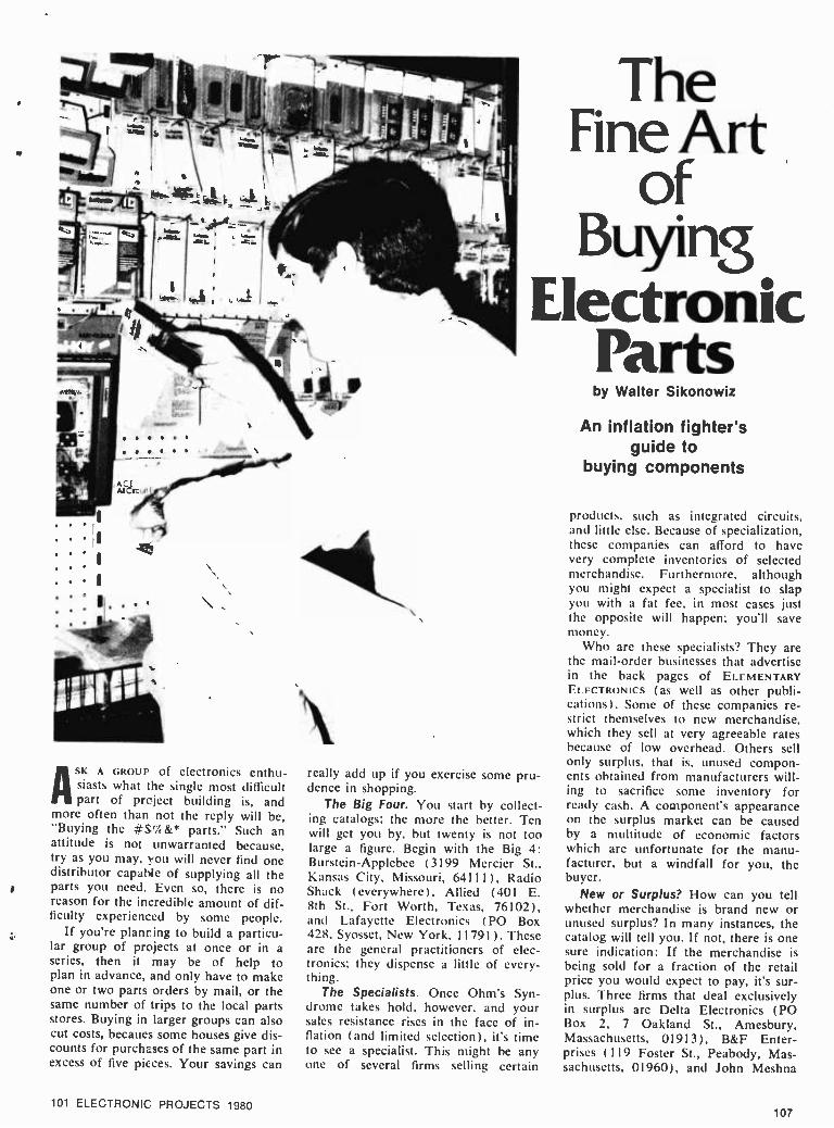
ASK A GROUP of electronics enthu- siasts what the single most difficult part of project building is, and
more often than not the reply will be, "Buying the #$4 &* parts." Such an attitude is not unwarranted because, try as you may, you will never find one distributor capable of supplying all the parts you need. Even so, there is no reason for the incredible amount of dif- ficulty experienced by some people.
If you're planring to build a particu- * lar group of projects at once or in a
series, then it may be of help to plan in advance, and only have to make one or two parts orders by mail, or the same number of trips to the local parts stores. Buying in larger groups can also cut costs, becaues some houses give dis- counts for purchases of the same part in excess of five pieces. Your savings can
101 ELECTRONIC PROJECTS 1980
The Fine Art
of Buying
Electronic Parts
really add up if you exercise some pru- dence in shopping.
The Big Four. You start by collect- ing catalogs; the more the better. Ten will get you by, but twenty is not too large a figure. Begin with the Big 4: Burstein -Applebee (3199 Mercier St., Kansas City, Missouri, 6411 1 ), Radio Shack (everywhere), Allied (401 E. 8th St., Fort Worth, Texas, 76102), and Lafayette Electronics (PO Box 428, Syosset, New York, 11791). These are the general practitioners of elec- tronics; they dispense a little of every- thing.
The Specialists. Once Ohm's Syn- drome takes hold, however, and your sales resistance rises in the face of in- flation (and limited selection), it's time to see a specialist. This might he any one of several firms selling certain
by Walter Sikonowiz
An inflation fighter's guide to
buying components
products, such as integrated circuits, and little else. Because of specialization, these companies can afford to have very complete inventories of selected merchandise. Furthermore, although you might expect a specialist to slap you with a fat fee, in most cases just the opposite will happen; you'll save money.
Who are these specialists? They are the mail -order businesses that advertise in the back pages of ELEMENTARY ELECTRONICS (as well as other publi- cations). Some of these companies re- strict themselves to new merchandise, which they sell at very agreeable rates because of low overhead. Others sell only surplus, that is, unused compon- ents obtained from manufacturers will- ing to sacrifice some inventory for ready cash. A component's appearance on the surplus market can be caused by a multitude of economic factors which are unfortunate for the manu- facturer, but a windfall for you, the buyer.
New or Surplus? How can you tell whether merchandise is brand new or unused surplus? In many instances, the catalog will tell you. If not, there is one sure indication: If the merchandise is being sold for a fraction of the retail price you would expect to pay, it's sur- plus. Three firms that deal exclusively in surplus are Delta Electronics (PO Box 2, 7 Oakland St., Amesbury, Massachusetts, 01913), B &F Enter- prises (119 Foster St., Peabody, Mas- sachusetts, 01960), and John Meshna
107

Parts Inc. (PO Box 62, E. Lynn, Massachu- setts, 01904). Others, like Poly Paks (PO Box 942, South Lynnfield, Mass., 01940), or Herbach.4 Rademan (401 E. Erie Ave., Philadelphia, Penn., 19134), offer a mixture of surplus and brand new stock. Regardless of whether the merchandise is new or surplus, all firms offer some guarantee of satisfac- tion.
In order to get better acquainted with the various suppliers, let's survey the market item -by -item. In the follow- ing paragraphs, whenever a specific company is mentioned in connection with a component, it is only because that firm is particularly strong in a certain area. Some degree of overlap- ping does exist among all firms, how- ever, so don't assume that any one supplier is being recommended to the exclusion of all others.
Integrated Circuits. Although hu- man life is based on the chemistry of carbon, it is the chemistry of silicon that now forms the basis for our busi- ness and industry, thanks to the in- tegrated circuit. Because of their tre- mendous importance, integrated circuits are sold by almost every electronics supplier, big or small. You'll find that the Big 4 have quite respectable IC inventories, but prices are relatively high, and selection is not complete. Jameco Electronics (1021 Howard St., San Carlos, Calif., 94070), and An- crona Corp. (PO Box 2208, Culver City, Calif., 90230) feature perhaps the widest selections of ICs; linear, TTL, CMOS. DTL, ECL, LSI and so forth. Jade Computer Products also of- fers a good selection of ICs in their cat- alog.
Circuit Specialists (PO Box 3047, Scottsdale, Ariz., 85257) is a nice company to do business with, since they require no minimum -size order. In ad- dition to a wide range of the standard ICs, Circuit Specialists carries special numbers from RCA, Motorola, and
You can buy bulk com- ponents at next -to- nothing prices if you buy untested, surplus parts. Poly Paks is a popular bulk supplier and two of their packs are shown here. Most of the parts are use- able.
Mostek. Digi -Key (PO Box 677, Thief River Falls, Minn., 56701) also fea- tures a wide assortment, including some circuits difficult to find elsewhere. Last, but not least, there is Solid State Sates (PO Box 74A, Somerville, Mass., 02143). Although this company's se- lection may be a trifle smaller than some, its service is like the fabled "greased lightning."
Occasionally, you are going to fe- ceive a dud. When this happens, it's best not to go berserk. A calm request for a replacement is usually accom- modated very quickly. After all, these companies want your continued busi- ness in the future. As a precautionary measure, you might consider ordering two of each IC. The chances of getting one dud are so small that the proba- bility of receiving two duds simulta- neously is infinitesimal. You can use the extra IC, if it is good, in a future project.
Occasionally, the inevitable happens, and you will find yourself with an in- operative circuit. If you have any rea- son to suspect the IC as the culprit, either from poor handling technique, or from having eliminated any other pos- sible causes, a spare IC will cure many late -night headaches caused by projects that have no good reason not to work. Try the new IC before you burn the schematic!
Discrete Semiconductors. This cat- egory is an exceptionally broad one. Included arc: bipolar transistors, FETs,
Since a great many people have trouble remembering the color code, a useful aid to sorting surplus resistors is an old tie box with the color code marked inside the lid.
108
SCRs, diodes, UJTs and so on. As in the case of ICs, almost everyone sells some discrete semiconductors, but few vendors stock each part number. Be- fore giving up an elusive part, try either Hanifin Electronics Corp. (P.O. Box 188, Bridgeport, PA 19405), or the Ancrona Corp. These two firms have perhaps the most extensive listings of discretes.
Most suppliers offer special discounts to encourage volume buying of parts. This appeals directly to the squirrel - ish instincts of the electronics hobby- ist, but be careful. Just like that greedy little tree -dweller, you will probably horde more than you can ever use. If you must stockpile parts, do it sensi- bly. Choose those discrete components that are most frequently used: 2N3906 PNPs, 2N3904 NPNs, 1N914 switch- ing diodes, 1N4003 rectifiers and so forth. Avoid the high -wattage zener diodes now appearing in surplus. To- day, integrated circuits have supplant- ed zeners as regulators at all but the lowest power levels.
Resistors. Buying from one of the larger retailers, you can expect to pay around 10 cents a piece for carbon - composition resistors. Compare that with the typical 4 -cent selling price from the specialist firms, and the choice of a supplier is obvious. Resis- tors are one class of component that can be sensibly stockpiled. Buy half - watters with a 5% tolerance. They cost only a bit more than 10% resistors
Try to build up a supply of transistors, diodes, ICs and electro- optical devices.
101 ELECTRONIC PROJECTS 1980
t

ADDRESSES OF PARTS SUPPLIERS:
Ace Electronics, 5400 Mitchelldale Houston, TX 77092
Active Electronics Sales Corp. 12 Merser Rd., Natick, MA 01701
ALdelco, 228 E. Babylon Tpk. Merrick, N.Y. 11566
Allied Electronics, 401 E. 8th St. Forth Worth, TX 76102
Ancrona Corp., P.O. Box 2208 Culver City, CA 90230
B &F Enterprises, 119 Foster St. Peabody, MA 01960
Bullet Electronics, P.O. Box 1944 Dallas, TX 75219
Burstein -Applebee, 3199 Merceir St. Kansas City, MO 64111
Calectro Products of GC Electronics Rockford, IL 61101
Chaney Electronics, P.O. Box 27038 Denver, CO 80227
Circuit Specialists, P.O. Box 3047 Scottsdale, AZ 85257
Delta Electronics, P.O. Box 2 7 Oakland St., Amesbury, MA 01913
Diamondback Electronics Co. P.O. Box 194, Spring Valley, IL 61362
Digi -Key, P.O. Box 677 Thief River Falls, MN 56701
Digital Research Corp. P.O. Box 401247B, Garland, TX 75010
Electronics Distirbutors, Inc. 4900 N. Elston Chicago, IL 60630
ETCO Electronics, 521 Fifth Ave. New York, NY 10017
Formula International, Inc. 12603 Crenshaw Blvd. Hawthorne, CA 90250
Fuji -Svea, P.O. Box 3375 Torrance, CA 90510
Hanifin Electronics, P.O. Box 188 Bridgeport, PA 19405
Herbach and Rademan, 401 E. Erie Ave. Philadelphia, PA 19134
HobbyWorld, 19355 Business Center Dr., Northridge, CA 19324
Integrated Electronics 540 Weddell Dr., Sunnyvale, CA 94086
International Electronics Unlimited Village Square P.O. Box 449 Carmel Valley, CA 93924
Jade Computer Products 5351 W. 144th St. Lawndale, CA 90260
Jameco Electronics, 1021 Howard St. San Carlos, CA 94070
John Meshna, Inc., P.O. Box 62 East Lynn, MA 01904
Lafayette Electronics, P.O. Box 428 Syosset, NY 11791
Mouser Electronics, 11511 Woodside Ave. Lakeside, CA 92040
New Tone Electronics, P.O. Box 1738 Bloomfield, NJ 07003
Olson Electronics, 260 S. Forge St. Akron, OH 44327
Optoelectronics 5821 N.E. 14th Avenue Fort Lauderdale, FL 33334
Poly Paks, P.O. Box 942 South Lynnfield, MA 01904
Quest, P.O. Box 4430 Santa Clara, CA 95054
Radio Hut, P.O. Box 401247 Dallas, TX 75238
Radio Shack Consult your local phone book
Ramsey Electronics, P.O. Box 4072 Rochester, NY 14610
Signal Transformer Co., 500 Bayview Ave. Inwood, NY 11696
Solid State Sales, P.O. Box 74A Somerville, MA 02143
Steven Products, P.O. Box 698 Melville, NY 11746
Surplus Electronics Corp. 7294 N.W. 54th St., Miami, FL 33166
and save you the trouble of stocking two tolerances.
Most construction projects are de- signed to utilize resistors with a toler- ance of 10%, unless specified other- wise in the parts list.
Power resistors, with ratings from 5
to 100 watts, are available from the surplus dealers at incredible prices. Buy a small assortment. Power sup- plies and audio amps often need dum- my loads during checkout. and for such purposes these high -power resistors are ideal. If you do not have exactly the right resistance at hand, use serial and parallel combinations whose. net resis- tance is the desired value.
Don't forget those high -class resis- t tors, the metal -film precision units with
tolerances of 1 or better. You can get these from the larger retailers, but at 60 cents to one dollar apiece (often with a ten -piece minimum order) who needs them? Actually, for certain ultra - stable or low -noise circuits, precision resistors are mandatory. Active filters, accurate voltage dividers, and analog - computer circuits are but a few exam- ples. When you really need precision resistors, Hanifin Electronics can sup-
ply them at about 15 cents each. But because Hanifin is an industrial sup- plier, do not send in a 75( order; fif- teen dollars worth is a realistic mini- mum. Since Hanifin offers lots of good- ies besides resistors, you should have no trouble putting together a good - sized order.
Capacitors. The best all- around ca- pacitor that money can buy is the polystyrene type. It also happens to be one of the cheapest, a fortunate coin- cidence. Polystyrenes are available in the range from 5 pF to 0.5 -uF, but above .01 -uF, they begin to get bulky and expensive. Your best and most complete sources for these capacitors are Burstein -Applebee and Allied (ad- dresses supplied previously). Standard tolerances are 5'4 (super for a capaci- tor), with 2.57 and 1'ßi available at higher prices.
In the range from 0.01 -uF to 1 -uF, you are best off with mylar (polyester) capacitors. ( Mylars are available out- side this range, too.) Standard toler- ances are 20' and 10%. A great many firms carry mylar capacitors.
Above 1 -uF, most capacitors are alu- minum electrolytics, which are polar-
ized devices. One of their most im- portant functions is filtering, particular- ly in AC power supplies. Tolerances tend to he relatively loose since ap- plications rarely call for very precise electrolytic capacitors. Capacitances as
high as 40,000 -uF and beyond are available.
The aluminum electrolytic has a
more sophisticated cousin. the tanta- lum capacitor, which is commonly available in capacitances as high as
several hundred microfarads. Relative to the aluminum electrolytic, the tanta- lum features tighter tolerances (10q typically), lower leakage, and smaller size for equivalent capacitance. As a
result. tantalums are preferred over aluminum electrolytics in timing appli- cations. Both electrolytic types are stocked by many distributors.
Surplus capacitors are available, with perhaps the best source being Poly Paks (see above), at least in terms of variety. If you do buy surplus capaci- tors, play it safe and check each one on a capacitance meter. Ceramic by- pass capacitors for digital logic are available very cheaply as surplus, and so too are mylars. On the other hand,
101 ELECTRONIC PROJECTS 1980 109
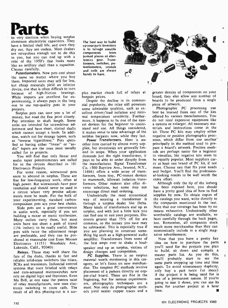
Parts be very cautious when buying surplus aluminum electrolytic capacitors. They have a limited shelf life, and once they dry out, they are useless. Most dealers are scrupulous enough not to do this to you, but you can end up with a
relic of the 1950's that looks more like an artillery shell than a capacitor. Choose carefully.
Potentiometers. New pots cost about the same no matter where you buy them. Imported units may sell for less, but cheap materials yield an inferior device, one that is often difficult to turn because of high- friction bearings. While imports are excellent for ex- perimenting, it always pays in the long run to use top -quality pots in your projects.
Surplus pots can save you a lot of money, but read the fine print closely. Pay attention to shaft length. Some units are intended for screwdriver ad- justment and have short. slotted shafts which cannot accept a knob. In addi- tion, watch out for strange tapers, such as "reverse logarithmic." Pots speci- fied as having either "linear" or "au- dio" tapers are the ones most usually called for in projects.
You will find that only linear and audio taper potentiometers are called for in the circuits described in 101
Electronics Projects. For some reason, wirewound pots
seem to abound in surplus. These are fine for low- frequency work, often at high power. But wirewounds have poor resolution and should never be used in
a circuit where very precise adjust- ments must be made. For the bulk of your experimenting, standard carbon - composition pots are your best choice.
Slide pots are a great convenience in audio work, especially if you are building a mixer or music synthesizer. Many outlets carry them, but most units have too short a path of travel (11/4 inches) to be really useful. Slide pots with twice the adjustment range are preferable, and they can be pur- chased at reasonable cost from Mouser Electronics (1 1511 Woodside Ave., Lakeside, Calif., 92040).
Relays. These may well share the fate of the dodo, thanks to fast and reliable solid -state switchers like triacs, SCRs and transistors. Industrial control systems that once bristled with relays and cam- actuated microswitches now rely on digital logic and thyristors. Even Ma Bell, at one time the patron saint of relay manufacturers, now uses elec- tronic switching to route calls. The result of all this phasing -out is a sur-
The best way to build up your parts inventory is to salvage useable components from junked pieces of elec- tronics gear. Trans- formers, switches, po- tentiometers, crystals and coils are always handy to have.
plus market chock full of relays at bargain prices.
Despite the decline in its commer- cial popularity, the relay still possesses some admirable qualities, such as ex- cellent driver; load isolation and mini- mal temperature sensitivity. Further- more, it happens to be one of the easi- est devices for the beginner to tinder - stand and use. All things considered, it makes sense to take advantage of the surplus bargains now, while they last.
Power Transformers. Here is an- other item carried by almost every sup- plier, but inventories are generally lim- ited in scope. When your application demands just the right transformer, it pays to be able to order directly from the manufacturer. Signal Transformer Co. (500 Bayview Ave., Inwood, N.Y., 11696) offers a wide array of trans- formers, from tiny, PC -mount devices to mammoth, kilowatt isolation trans- formers. Other makers also offer di- verse selections, but some may not encourage direct mail ordering.
Undoubtedly the most economical way of securing a transformer is
through a surplus dealer like Delta. Many kinds of transformers end up as surplus, and with just a little luck you can find one to suit your purposes. Dis- counts greater than 75% off list are common, so the money you save may be substantial. This is especially true if you are planning to construct some- thing big such as a high -powered audio amplifier. Transformers from some of the best amps ever to shake a loud-
speaker end up as surplus, victims of design changes and competition.
PC Supplies. There is no surplus material worth mentioning in this cat- egory, so let's focus on new merchan- dise. The simplest PC methods involve placement of a pattern directly on cop- per -clad board. These are fine in the beginning, but for serious experiment- ers, photographic techniques are a must. Not only do photographic meth- ods yield neater copper traces and a
greater density of components on your board, they also allow any number of boards to be produced from a single piece of artwork.
Photographic PC processing can best be learned from one of the kits offered by various manufacturers. You do not need expensive equipment like a camera or enlarger. All necessary ma- terials and instructions come in the kit. These PC kits may employ either negative or positive photographic proc- esses, which differ from one another' principally in the method used to pre- pare a board's artwork. Positive meth- ods are perhaps easier for a beginner to visualize, but negative kits seem to be equally popular. Most suppliers car- ry at least one brand of PC kit, if not more. Choose one that fits your needs and budget. You'll find the profession- al- looking results to be well worth the extra effort.
Although only the tip of the iceberg has been exposed here, you should have a pretty good idea of how to find supplies by now. To obtain copies of the catalogs you want, write directly to the companies mentioned in the text. Note that our coverage has been by no means exhaustive. Undoubtedly other worthwhile catalogs are available, so hunt carefully through the back pages, too. Remember, all companies stock much more merchandise than they can economically include in a single mag- azine advertisement.
Now that you have a pretty fair idea on how to purchase the parts you'll need for the projcets you plan to build, sit down and compile a master parts list. As you do this, you'll probably start to see the same parts cropping up time and time again. To avoid unnecessary duplicity, only buy a part twice (or more) if the project it is being used for is one of a permanent nature. If you're going to tear it down, you can use its parts for another project at a later time.
110 101 ELECTRONIC PROJECTS 1980

THE
SPEiAL Power your projects, spend pennies for parts.
by Herb Friedman
Between 555 timers, TTL, CMOS, opamps and run of the mill transistor projects, the average experimenter is often faced with the need for a regu- lated power supply with a range of about 5 to 15 volts -just to try out a breadboard project. If you've priced any regulated supplies lately you know they don't come cheap. Maybe, just maybe, you might get one for $30 or $35.
With a little careful shopping, a rea- sonably stocked junk box and one or two "brand new" components you can throw together a regulated supply cost- ing less than $10 that will handle most of your experimenter power supply re- quirements. One of these Junk Box Spe- cials is shown in the photographs and schematic. The range of this model is 5 to 15 volts DC at currents up to 1
ampere. One of the common, 3- terminal regulators which are now flooding the surplus market provides everything in the way of regulation. Depending on the source, the regulator will cost you from $1 to $2.50; the higher prices often in- clude ar insulated mounting kit (worth about 25- cents).
5 to 15 volts from one 3- terminal reg- ulator? Correct. If regulator ICI's col- lector terminal is connected to a voltage divider across the output -RI and R2- the output voltage will he that at the junction plus the volage rating of the regulator, which in this instance is 5 volts. Só, when potentiometer R2 is adjusted so its wiper is grounded the power supply's output is that of the regulator, 5 volts -perfect for TTL pro- jects. As R2 is advanced, increasing the resistance from ICI's collector to ground, the voltage output increases.
Getting the parts. There are plenty of parts around to build this supply for
under $10. It you go out and round up all new" components the cost is likely
to go well over $30, so forget about new parts. Power trahsformer TI can he 18 volts at I ampere (or rated at higher current, though the supply's maximum output is 1 ampere), or 36 volts center -tapped at 1 ampere or more. Both the 18 volt and 36 volt transformers are glutting the surplus market. If you get an 18 volt trans- former use the bridge rectifier shown in the schematic. If you get a 36 volt C.T. transformer use the full -wave recti-
RUBBER ANTI-SCRATCH FEET
TI
C2 ICI
To prevent scratching your workbench apply rubber anti -scratch feet or bumpers on the bottom of the cabinet. They are available ill most hardware and houseware stores.
fier shown below the schematic. The diode rectifiers SRI through SR4, are type 1N4001, I N4002, 1 N4003, or 1N4004, which are also glutting the surplus market. Just to show you the savings possible, at the time this article is being prepared you can buy fifteen surplus 1N4001s for $1. Just one single "general replacement" for the 1N4001 from a national supplier is selling for over 40- cents. Get the idea how to save costs on this project?
Capacitor Cl can be anything from 2000 to 4000 uF at 25 volts or higher. Look for an outfit selling surplus com- puter capacitors. If worse comes to worse you can get the value specified in the parts list in a Radio Shack store.
The 3- terminal, 5 volt regulator is another item easily found on the surplus market. With an adequate heat sink - such as the cabinet itself -the device can safely deliver 1 ampere. The unit shown in the photographs is a Motorola MC7805 (though you can substitute any similar type) obtained for $2.50 from Circuit Specialists. We have seen similar devices from other manufacturers selling for $1. The terminals B, C and E are indicated directly on the device or on the terminals -where they join the case. The collector (C) lead is con- nected to the IC's metal tab, and is normally grounded. Note that in this project, however, the collector terminal. and therefore the tab, is not grounded. You must use an insulated mounting kit consisting of a mica insulator and a shoulder washer. Place the insulator between the IC's body and the cabinet, or the tab and cabinet, and slip the shoulder washer into the opening (hole) in the body or tab. Pass the mounting screw from outside the cabinet through the mica washer, through the IC, and
101 ELECTRONIC PROJECTS 1980 111

JUi4K loX through the shoulder washer. Secure with a 1/4 -inch (or smaller, not larger) nut hand -tightened against the shoulder washer. Before going any further check with an ohmmeter to be certain the col- lector terminal is insulated from the cabinet.
Connecting wires are soldered di- rectly to ICI's terminal leads; use a
heat sink such as an alligator clip on each terminal if you have a large (greater than 40 watts) iron. Since the layout is not important,we suggest the arrangement shown, with ICI posi- tioned between two mounting strips so RI can span across the strips and he soldered to ICI's collector terminal.
Finally, we come to the meter, a de- vice that has become slightly more expensive than a barrel of Arabian oil. Any meter that can indicate at least the range of 0 to 15 VDC is adequate. The EMICO 0 -30 VDC meter shown in the photographs was selling in one local store for $7.95, while we bought ours almost down the block as "surplus" for $2.99. A good source for surplus meters is Fair Radio Sales. You might not end up with a meter case that looks
TI
BPI
WITH BRIDGE RECTIFIER
TI SRI
SR2
TCI
ALTERNATE FULL -WAVE RECTIFIER
Virtually any DC voltmeter that can display the range of 0 to 15 volts can be used. The surplus market is loaded with less- than -S5 meters that are suitable if you don't mind a little extra scale coverage.
BP2
1
PARTS LIST FOR JUNK BOX SPECIAL
R1 -220 or 470 -ohms, lh watt, 10% (see text) R2- Potentiometer, 500 or 1000 -ohms (see
text) C1- 3300 -uF, 35 VDC (see text) (Radio Shack
272-1021 or equivalent) C2, C3 -0.1 uF Mylar
C4- 25 -uF, 25 VDC or higher M1 -DC voltmeter (see text) IC1- Motorola MC7805, 5 volt 3- terminal regu-
lator (see text) T1 -Power transformer, secondary 1 ampere
at 18 volts or 36 volts C.T. (see text) SRI, SR2, SR3, SR4- Silicon rectifiers (see
text) SI -SPST switch BPI, BP2-5.way binding posts Misc.- Cabinet, terminals strips, etc.
suitable for NASA, but the output volt- age doesn't care two hoots whether the meter is a modern $25 dollar model or a surplus- special for a buck ninety -nine.
Power switch SI can be a separate
If you've had experience with assembly in tight quarters, you can shoe- horn the power supply into a standard 3 x 4
x 5 -inch Mini - box. If your sol- dering iron is so big it burns ad- jacent wires when you make a connection, use a larger size cabinet.
112
In order to han- dle a full am- pere, the IC regulator must be heat sinked to the cabinet. Make certain the collector and its attached sink tab (the back of the package) is in- sulated from the cabinet. Use silicon grease to insure heat transfer from the IC to the cabinet.
SPST as shown in our project, or it can be part of R2. But keep in mind that a separate Si allows you to turn the supply on and off without affecting voltage control R2's adjustment.
Finally, we come to R1 and R2. You will note that the schematic shows two values for each. One value for each resistor is in brackets (parenthesis). You can use either set of values as long as they are matched. If R2 is 500 ohms R1 is 220 ohms; if R2 is 1000 ohms R1 is 470 ohms. The reason we show both sets of values is because 500 and 1000 ohm potentiometers appear on the sur- plus market from time to time, but usually not together. This way, you can use whatever is available at low cost.
CHECKOUT. Set potentiometer R2 so the wiper shorts to the end connected to ICI's collector terminal, thereby con- necting the collector directly to ground.
(Continued on page 114)
101 ELECTRONIC PROJECTS 1980

40 Integrated Circuit Projects (Continued from page 86)
zero, an illegal voltage level, or the presence of pulses at any frequency or duty cycle. The presence of a continu- ous logic level is detected by IC 1 A and IC 1 B, which are voltage comparators set to detect levels of 2.0 and 0.8 volts respectively. The presence of pulses is detected by a 555 timer connected as a one -shot multivibrator which illuminates an LED for about 0.5 second if pulses are present. A second 555 timer is used to disable IC2 for about 0.5 second each time it fires. This provides a flashing LED regardless of the frequency of the detected pulses. The circuit is powered by the 5 volt supply feed- ing the digital circuit under test. To calibrate the circuit, apply a voltage of 2.0 volts DC to the logic input termi- nal. Adjust R1 so that D1 is on the borderline between off and on. Apply 0.8 volts to the logic input terminal and adjust R2 so that D2 is on the borderline between off and on. When using the circuit either D1 or D2 or both must be lit to indicate a correct logic level. If both are out, the detected voltage is between 0.8 and 2.0 volts and is an illegal voltage level. D3 will flash only if there are pulses present on the line under test.
PARTS LIST FOR TTL LOGIC PROBE C1 -10 -uF electrolytic capacitor, 25 VDC C2- 0.01 -uF ceramic capacitor, 15 VDC C3 -1 -uF electrolytic capacitor, 15 VDC C4- 0.01 -uF ceramic capacitor, 15 VDC C5 -1 -uF electrolytic capacitor, 15 VDC 01, 02, D3 -large LED IC1 -339 quad comparator IC2, IC3 -555 timer
LOGIC PROBE
R I3
R2
ßC2 =
R14
R5
LOGIC
3
ILIA 4
ÌI IC1B
IO
12
R3
LOGIC Od/ O D2
R4
13
O
R8
41, Q2- 2N4401 R1, R2- 50,000 -ohm linear -taper potentiometer R3, R4- 220 -ohm, 1 -watt resistor R5. R7. R14- 100,000 -ohm, 1 -watt resistor R6, R10- 470,000 -ohm, 1 -watt resistor R8. R11, R12- 4,700 -ohm, 1 -watt resistor R9- 180 -ohm, / -watt resistor R13- 10,000 -ohm, 1/2-watt resistor
"1 assumed that when the sales- man said that there were no
tubes and no moving parts, he meant it was all solid state."
lyl ,wr- i 11 1 ri1d,,,tl6
I'II, ir 11{1`NI.IF,.1//i h+Í Ì"1lll l¡" ^ÏTtr, 14/ ,Wrw I I hl /%l ,1
. rr IIyN/rnll Y.r. A "Sorry bub, all I have on the
truck are wall phones."
"Say, Frank, ever notice the catchy, hypnotic rhythm that data makes as it's processed ... Frank
. Frank ... Ney, Frank...."
101 ELECTRONIC PROJECTS 1980 113
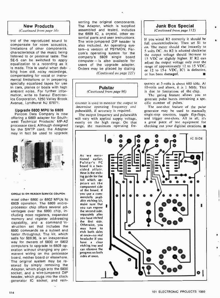
New Products (Continued from page /0)
trol of the reproduced sound to compensate for room acoustics, limitations of other components, characteristics of the music being listened to or personal taste. The SE -5 can be switched to apply equalization to a recording as it is made. This is useful when dub- bing from old, noisy recordings, compensating for vocal or instru- mental limitations or in preparing specially equalized tapes for use in cars, planes or boats with high ambient noise. For further infor- mation, write to Sansui Electron- ics Corporation, 1250 Valley Brook Avenue, Lyndhurst NJ 07071.
Upgrade 6800 MPU to 6809 Percom Data Company is now
offering a 6809 adapter for South -. west Technical Products' MP -A2 processor card. Although designed for the SWTP card, the Adapter may in fact be used to upgrade
CIRCLE 51 ON READER SERVICE COUPON
most other 6800 or 6802 MPUs to 6809 operation. The 6809 micro- processor chip offers several ad- vantages over the 6800 chip, in- cluding more registers, expanded memory and register addressing capability, and a command in- struction set that includes the 6800 commands as a subset and faster throughout. The kit. which sells for $69.96, is an inexpensive way for owners of 6800 or 6802 computers to upgrade to 6809 op- eration without changing any per- manent wiring on the processor board, mother board or elsewhere. The original system may be re- stored by simply removing the Adapter, which plugs into the 6800 socket, and a wire -jumpered DIP header, which plugs into the clock generator IC socket, and rein-
serting the original components. The Adapter, which is supplied assembled and tested, includes the 6809 IC, a crystal, other es- sential parts and user instructions. The wire -jumpered DIP header is also included. An operating sys- tern-a version of PSYMON. Per - com's operating system for the company's 6809 single board computer - is also available for users of the upgrade adapter. Orders may be placed by dialing
(Continued on page 117 )
Junk Box Special (Continued from page 112)
If you wired R2 correctly it should be full counterclockwise. Then set Si to on. The meter should rise instantly to 5 volts DC. As R2 is adusted clockwise the output voltage should increase to 15 VDC or slightly higher. If R2 can adjust the output voltage only over the range of approximately 12 to 15 VDC, or 12 to 15+ VDC, ICI is defective. or has been damaged.
Pulstar (Continued from page 96)
counter is used to monitor the output to determine operating frequency and pulsewidth. if accuracy is required.
The output frequency and pulsewidth will vary with applied supply voltage, mostly on the high range. On that range, the maximum operating fre-
quency at 5 -volts is about 600 kHz. At 10 -volts and above, it is 1 MHz. This is due to limitations of the chip.
The gating feature allows you to generate pulse bursts containing a spe- cific number of pulses.
The one -shot feature of the pulse generator may be used to manually single -step counters, toggle flip -flops, and trigger one- shots. All in all. it's a great piece of test equipment for checking out your digitital creations.
As we men- tioned earlier, Pulstar's PC board is a two - sided affair. Here is the etch- ing guide for the foil which ap- pears on the component side of the board. If you use a com- mercially avail- able etching kit, make sure that you can expose the second side. separately after you have etched the first side. Otherwise, you may have to etch both sides at once -no real headache if you have a clear etching tray and can observe the progress on both sides at once.
114 101 ELECTRONIC PROJECTS 1980

(!...,ITERATURE LIBRARY
400. Continental Specialties provides new product into in its catalog of Testing and Design Instru- ments. A Digital Capacitance Meter and Tri -Mode Comparator are just some of the featured projects.
399. "Firestik" Antenna Company has introduced a new and informative product catalog on top - loaded, helically wire -wound antennas and mounts.
398. Hamtronics, Inc. has announced a new model R110 VHF AM Receiver Kit which employs an AM detector and a dual -loop agc system. A complete catalog is yours for the asking!
397. Instant Software, Inc. is offering a special holiday catalog for all kinds of year 'round soft- ware package gift- giving, as well as their regular microcomputer catalog.
396. Creative Computing's first software catalog of various education and recreation simulation pro- grams as well as sophisticated technical applica- tion packages is available now.
395. OK Machine and Tool Corporation features the new PRO -1 Digital Logic Probe on the cover of its latest catalog of wire wrapping and other elec- fronic assembly tools.
394. KEF Electronics Ltd. is offering two speaker systems in kit form at a significant cost -savings. The Model 104aB and the Cantata can be easily assembled and may be auditioned before pur- chasing.
389. You can't buy a bargain unless you know about it! Fair Radio Sales' latest electronics sur- plus catalog is packed with government and com- mercial buys.
388. SWLs need Gilter's Shortwave Mail Order Cata- log for economy one -stop armchair shopping. From top-notch rigs to reporting pads, Gilfer supplies all your hobby needs.
327. Avarrti's new brochure compares the quality difference between an Avanti Racer 27 base loaded mobile antenna and a typical imported base loaded antenna.
382. A new catalog crunched full of military, com- mercial and industrial surplus electronics for every hobbyist is offered by B4F Industries. 44 pages of bargains you've got to see!
384. 8dK- Precision has issued BK -10, a condensed catalog describing their oscilloscopes, semi-con- ductor testers as well as test instruments for CB, radio and TV repair.
310. Compumart Corp., formerly NCE, has been selling computers by mail since '71, and is offer- ing a 10 -day return policy on many items featured in their latest catalog.
322. Radio Shack's latest full color catalog, "The Expanding World of TRS -80," is out now, packed with up to the date information on this microcom- puter. Specifications for the new Model 11 as well as the Model I are included.
386. If you're lookng for books on computers, calcu- lators, and games, then get BITS, Inc catalog. It includes novel items.
335. The latest edition of the TAB BOOKS catalog describes over 450 books on CB, electronics. broad- casting, do- it- yourself, hobby, radio, TV. hi -fi, and CB and TV servicing.
338. "Break Break," a booklet which came into existence at the request of hundreds of CBera, con- tains real life stories of incidents taking place on America's highways and byways. Compiled by the Shakespeare Company, it is available on a first come, first serve basis.
345. For CBers from Hy -Gain Electronics Corp. there is a 50 -page, 4 -color catalog (base, mobile and marine transceivers. antennas, and accessories).
393. A brand new 60 -page catalog listing Simpson Electric Company's complete line of stock analog and digital panel meters, meter relays. controllers and test instruments has just come out.
385. Amateur Rado butts and biginners will want the latest Ham Rad.o Communications Bookstore catalog. Its packed with items for the Ham.
373. 48 -page "Electronic Things and Ideas Book" from ETCO has the gadgets and goodies not found in stores and elsewhere.
382. Buys by the dozens in Long's Electronics super "Ham Radio Buyer's Guide." Good reading if you're in the ma-ket for a complete station or spare fusas
383. If you're a radio communicator, either ham, SWL, scanner buff or CBer. you'll want a copy of Harrison Radio's "Communications Catalog 1979 " Just what the shack book shelf nerds.
380. If your projects call for transistors and FETS, linear and digital ICs, or special solid -state parts. then look into Adva Electronics' mini -catalog for rock bottom prices.
301. Get into the swing of microcomputer and microprocessor technology with CREI's new Pro- gram 680 New 56 page catalog describes all pro- grams of electronics advancement.
305. A new 4 -page directional beam CB antenna brochure is available from Shakespeare. Gives complete specs and polarization radiation patterns for their new fiberglass directional antennas.
371. Your computer system needn't cost a fortune. Southwest Technical Products offers their 6800 computer complete at 5395 with features that cost you extra with many other systems.
308. Antenna Specialists has a new 32 -page CB and monitor antenna catalog. a new amateur antenna catalog. and a complete accessory catalog.
377. John J. Meshna, Jr., Inc. has a super saver catalog out (SP -16) featuring walky talkies and radar detectors.
hmi
330. There are nearly 400 electronics kits in Heath's new catalog. Virtually every do- it- yourself interest is included -TV, radios,' stereo and 4- channel, hi -fi. hobby computers, etc.
392. The opening of the new Software of the Month Club has been announced by Creative Discount Soft- ware, which is giving out membership enrollment applications now. The Club plans to have separate branches for users of the Apple II, TRS -80, Ohio Scientific, Exity, Pet and CP'M based systems. 390. Whitehouse d Co., your "hard to find parts specialist," offers over a dozen parts and kits in their latest catalogue, featuring an entire section on gunnplexers for Amaeur Radio buffs. 313. Get all the facts on Progressive Edu -Kits Home Radio Course. Build 20 radios and electronic cir- cuits; parts. tools, and instructions included. 320. Edmund Scientific's catalog contains over 4500 products that embrace many sciences and fields. 328. If you are into audio ham radio. project build ing. telephones. CB or any electronics hobby you'll want McGee's latest catalog of parts and gadgets 333. Get the new free catalog from Howard W. Sams. It describes 100's of books for hobbyists and technicians -books on projects, basic elec- tronics and related subjects. 354. A government FCC License can help you qualify for a career in electronics. Send for Infor- mation from Cleveland Institute of Electronics. 355. New for CBers from Anixter -Mark is a colorful 4 -page brochure detailing their line of base station and mobile antennas. including 6 models of the famous Mark Heliwhip.
391. A new software products catalog for the Apple Il Computer has just been issued by Charles Mann d Associates. The booklet contains business ac- counting, accounts rece vable, inventory, BASIC teaching and other special purpose business appli- cations. 359. Electronics Book Club has literature on how to get up to 3 electronics books (retailing at 358.70) for only 99 cents each . plus a sample Club News package. 311. Midland Communications' line of base. mobile and hand -held CB equipment. marine transceivers, scanning monitors, plus a sampling of accessories are covered in a colorful 18 -page brochure.
101 ELECTRONIC PROJECTS 1980 EDITION Box 1849, G.P.O. Void After August 10, 1980 New York, NY 10001 Please arrange to have the literature whose numbers I have circled below sent to me as soon as possible. I am enclosing 500 for each group of 10 to cover handling. (No stamps, please.) Allow 4 -6 weeks for delivery.
301
335
383
396
305 306
338 345
384 385
397 398
310
354
386
399
311
355
388
400
313
359
389
320 322 327 328 330 333
362 371 373 377 380 382
390 391 392 393 394 395
300 Enter my subscription to ELEMENTARY ELECTRONICS for 6 issues at $3.98. Check enclosed. Canada and all other countries $5.00. HOD021
NAME (print clearly)
ADDRESS
CITY STATE ZIP
101 ELECTRONIC PROJECTS 1980 115

......................M.......................... Classified
MARKET . ......... ... . ...... . . . . . . . . . . . . . . . . . . . . . . . . . . . . . . . . :
101 ELECTRONIC PROJECTS -is published annually. The rate per word for CLASSIFIED ADVERTISEMENTS
is $1.00 payable in advance -minimum ad $15.00. Capitalized words 400 per word additional.
ADDITIONAL INCOME BUSINESS OPPORTUNITIES- Conf'd
EARN EXTRA INCOME stuffing envelopes at FREE Catalog. JEWELRY available wholesale. Big home. Free supplies. complete assistance. SSAE: profits. Northway Distributors, 31 King, Dept. Al, Home Enterprises, Dept. 2802. P.O. Box 1138. St. St. Charles, Ontario POM 2W0. Helena. OR 97051.
BECOME COMMISSION MAILER. How? Write: Executive YEARLY! nes new order ffer
Grahams. DPBX 99371, Tacoma, WA 98499. livery type business-helping others. Offer limited. Free secrets! Treasure -R3D. Colorado 90405.
ANTIQUES, ARTS 6 CURIOS
INDIAN Relira Jewelry, Western Americana, Weap- ons. Mallorder Catalogues, Auctions. Important Op- portunity for Investors, Collectors National Auctions, 6518 Van Nuys, Van Nuys, CA 91401.
BLUEPRINTS, PATTERNS b PLANS
LINEAR AMPLIFIERS, 100 or 200 watt, 2.30 MHz. Omnipolarized ANTENNA. 300 MHz COUNTER. Modulation BOOSTER -VOX. Plana $3.00 each. 810.00/ all. Catalog of others! PANAXIS, Box 130 -OPS, Paradise, CA 95969.
NEW CRAFT PRINT CATALOG-Choose from over 100 great easy -to -build plans. Send $1 50 (completely refunded with your first order). BOAT BUILDER, (CP Div.) -380 Lexington Ave , New York. NY 10017.
BOOKS L PERIODICALS
AIR -CONDITIONING: Layman's Practical Guide for Air- Conditioning Repair. $4.95- "You S Your Air - Conditioner." Box 3468, San Antonio, Texas 78211. Money Back Ouarantee.
HOW to save tax dollars when you sell your house. $3.95. J. N. Haynes Inc.. Box 74 -K, Clear, AK 99704.
BF by mall. Bem's Book Service, 2914 E. South - cross, San Antonio, TX 78223.
STILL BAFFLED? Read "THE KEY to the Assas- sination of John F. Kennedy," by Edmund Johnston. Fully illustrated by Tom Wills. $3.00 plus 54e postage to THE KEY, P.O. Box 534, Bronx, NY 10462.
CBer's! Personalized CB decal with a 1 -year aub- scription to Elementary Electronics only 83.97. E /E, the magazine that covers CB and all areas of radio communication. Send check: Elementary Electronics. Decal Dept., 380 Lexington Ave., New York, NY 10017.
BUSINESS OPPORTUNITIES
SYNTHETIC LUBRICANTS. Join nation's largest marketer. No investment. No Inventory. Bayview, 3230 Minnesota, Duluth, MN 55802.
STAY HOME! EARN BIG MONEY addressing en- velopes. Genuine offer 10g. Lindco, 3636 -DA. Peter- son. Chicago 60659.
MAILORDER opportunity! Start profitable home business without experience or capital. Write for free book and details. No obligation. Gil Turk, Dept. 572, Montvale, NJ 07645.
$500 CASH advance available. Stuff 1000 envelopes. Free detalla. Dept. H, Box 7550, The Woodlands, TX 77380.
CIRCULAR MAILERS needed. Work from home. Earn hundreds 888 weekly. No experience needed. Department 04 -02. Box 1060, Orangepark. FL 32073.
RICHES IN FOUR STEPS! Discover how to select. price, sell, profit from your opportunity. Send 25e. Dennis, Box 12699C, New Brighton, MN 55112.
$500 Weekly Cash Advance Possible! Exciting, Easy Mailing Service. Free Details. Dept. B, Box 2505, Wichita Falla, TX 78307.
MAILORDER Business. Complete starter kit $2.00. Holland, 23300 W. Arata 2145. Troutdale, OR 97060.
81800 MONTHLY CLIPPING NEWSPAPERS at home!!! Spare time. Start immediately. No experi- ence required. Free report. Send self- addressed stamped envlope. Alpha, Box 131 -WCBB, Van Nuys, CA 91401.
MAKE money writing and selling simple informa- tion. Rush $11.00. Starts YOU ln business. Guaran- teed! Falconer, Box 20102 -D. Indianapolis, IN 46220.
$350.00 Weekly Possible! Home Program! Day, 820 -A Gleam, Louisville, KY 40214.
TREMENDOUS Profits! Wholesaling specialty items. 2,500 items available. Your the Boas. $10. brings Wholesales Kit. Refundable. Roberts Specialty Merchandise Company, 244 Bernard Drive, Buffalo Grove, IL 80090.
$1200 MONTHLY CORRECTING STUDENTS' LESSONS at home!!! Spare time. Start immediately. No experience required. Free report. Send self -ad- dressed stamped envelope. Horizon. Box 1685 -WCBB, Las Vegas. NV 89101.
$1000 monthly! Home mailing program! Kashkings, Box 485, Randolph, MA 02368.
ADVERTISE "Free" ln 95 Magazines -86.98. J&R Enterprises, Box 712 -IO, Pacoima, CA 91331.
$350 Weekly Mailing Letters. Free Details. Bronx - ville House, Box 311 -D, Bronxville, NY 10708.
$500.00 WEEKLY Mailing Circulars! Free Proof: Sunrise, Box 2096 -D, Niagara Falls, NY 14301.
BUY IT WHOLESALE
480 Weekly Possible. Amazing New Mailing Pro- HIGH Profit Cap Gun Key Chains, $4 80 D. gram. Details. Rasmussen DP50, 1747N. 450E. Ogden. Jewelry, $6.00 Dz. General Merchandise Catalog. Utah 844404. RJR, Dept. 508, 18 Church St., Mt. View, CA 94041.
$534.00 WEEKLY working three hours daily at home. $356.00 weekly working two hours daily. $178.00 weekly working one hour. Start immediately. Paid daily (advance)- $106.80, $71.20 or $35.60. WRITTEN EARNINGS GUARANTEE. FREE Bulletin, Applica- tion. FAS, Postal Unit 13703 -G, San Antonio, Texas 78213.
MAKE $1.00 Each Addressing Envelopes. We pay postage. No Limit. Beginners Kit $2.00. Colossi, Box 318 -D, Brooklyn, NY 11204.
$2000.00 Monthly mailing commission circulars Experience unnecessary. Free details. American, 1108 Colonial, Inkster. Michigan 48141.
$480.00 WEEKLY! "Guaranteed Home Mailing Pro- gram." Freedom. Box 30224 -DP, Denver, CO 80230.
$58.90 DAILY PAY. $353.88 WEEKLY HOME- WORK. IMMEDIATE INCOME. EARNINGS GUAR- ANTEE CERTIFICATE. FREE REPORT /APPLICA- TION. AAHIP, UNIT 29309 -H, MEDCENSTA, TX 78229.
FREE INFLATION -BEATER BOOK "2042 Unique, Proven Enterprises." Fabulous "Little Knowns." Work home! HAYLINGS- E14, Carlsbad, CA 92008
CB RADIO
CB TUNEUP,MODIFICATION REPORTS! $6 each, specify model. Free catalog. CB CITY, Box 1030D, Woodland Hills, CA 91365
COINS, CURRENCY b TOKENS
RARE cours market. Send $2 00 to Jefferson Press, P.O. Box 7055, Phoenix. AZ 85011.
DO IT YOURSELF
CURB Inflation with Booklet First Time Offered. "How to Sell Your Own Home and Save Money." Send $5: Hejak Enterprises, P.O. Box 245, La Porte, Indiana 46350.
EDUCATION b INSTRUCTION
BECOME ENGINEER. DJ. Start your own radio station, receive FCC license, equipment, records. Free details. "Broadcasting," Box 130 -GPO. Paradise, CA 95969.
EDUCATION 6 INSTRUCTON- Cent'd
UNIVERSITY DEGREES BY MAIL! Bachelors, Masters, Ph.D.s . Free revealing detail.. Coun- seling, Box 389 -EL -S, Tustin, CA 92680.
DO YOU KNOW "How to Write a Classified Ad That Pulls ?" Instructive booklet tells how. Also in- cludes a certificate worth 82.00 toward a classified ad in any of our publications. For your copy send $1.50 (plus 25e postage: to R. S. Wayner, Davis Publica- tions, Inc . Dept. CL, 380 Lexington Ave., New York, NY 10017
ELECTRICAL EQUIPMENT i SUPPLIES
REPAIR ELECTRIC MOTORS! GENERATORS! ALTERNATORS! Modelec, Box 7288, Kansas City, MO 64113.
FORMULAS 3 TRADE SECRETS
MAKE ALCOHOL FUEL LEGALLY,' Solar /conven- tional still plans and formulae. Details about Federal Permits. Only $10.00. RDA, Box 873, Concord, NC 28025.
FOR SALE -MISCELLANEOUS
GOLD! SILVER! Sell Direct Highest Yield USA Sources $10.00. Sterling, Box 6631, 23703.
CLOSEOUT Jewelry Sample and Price List $1.00. K&M Distributor, Platteville, RI 02823.
GIFTS THAT PLEASE
FREE GIFT catalog' UNIQUE gifts from around the world. Gifts, Box 11588 -TH, Spokane, WA 99211.
GOVERNMENT SURPLUS
JEEPS - $19 30! - CARS - $13.50! - 650,000 ITEMS! - GOVERNMENT SURPLUS - MOST COM- PREHENSIVE DIRECTORY AVAILABLE TELLS HOW, WHERE TO BUY - YOUR AREA - $2 - MONEYBACK GUARANTEE - "GOVERNMENT IN- FORMATION SERVICES," DEPARTMENT E -3. BOX 99249, SAN FRANCISCO. CALIFORNIA 94109.
HYPNOTISM
FREE Fascinating Hypnosis Information! Startling! DLMH, Box 487. Anaheim. CA 92805.
INVENTIONS WANTED
INVENTIONS, patents, wanted cash, royalty. Auto, electro- mechanical, mechanical devices. Housewares, etc. We develop, finance, manufacture and market from an idea to perfected product. Free evaluation and brochure. Request Kit DP. Pixonic Corporation, 22 Walter Street, Pearl River, NY 10965.
LOANS BY MAIL
BORROW $25.000 "OVERNIGHT." Any purpose. Keep indefiniteh! Free Report! Success Research. Box 29263 -SR, Indianapolis, IN 46229.
QUICK $CASH$ SIGNATURE Loans! Write: NAA, 507 -DG Fifth Ave., New York 10017.
BORROW $1,000 - $50,000 secretly - "overnight." Anyone! Credit unimportant. Repay anytime. In- credibly low interest. No interviews, collateral, co- signers. Unique "Financier's Plan." Full information, $2 (refundable(. Spectrum, 79 Wall St. -16, New York 10005.
GET cash grants -from Government. (Never repay.) Also, cash loans available. All ages eligible. Complete Information, $2 (refundable). Surplus Funds -DG, 1629 K. St. NW, 1502, Washington. DC 20006.
MAIL -ORDER OPPORTUNITIES
MAKE $1500 weekly! New discovery In envelope stuffing! Sensational! Free Secrets. Treasure- 118VV, Morrison, CO 80465.
MEMORY IMPROVEMENT
INSTANT MEMORY . NEW WAY TO RE MEMBER. No memorization. Release your PHOTO- GRAPHIC memory. Stop forgetting! FREE informa- tion. Institute of Advanced Thinking. 845DP Via - l.apaz. Pacific Palisades, CA 90272.
For Greater Classified. .. Savings ...Results ...and Profits... Place your ad in one of our SPECIAL COMBINATIONS: Combo =1, Combo »2 or Combo -#.3. Each
combination is designed to give your ad the largest oudence available, for further information write to
R. S. Wayner, Classified Advertising Director, Davis Publications, Inc. 380 Lexington Ave., N.Y., N.Y. 10017.

ìtlItlt>lt>f'
A
PLACE NNE
Classified i
To be included in the next issue, please send order and remittance to R S. Wayner, DAVIS PUBLICATIONS, 380 Lexington Ave., New York, N.Y. 10017
MISCELLANEOUS
FABULOUS Gems for Jewelry. Collecting. Gem - cutter to You! Save! Taylor's, 113 -A Martin. Indian Harbor Beach, FL 32937.
SAVE TO 90' WEEKLY on groceries!! Guaran- teed!! Information: Rush self addressed stamped en- velope plus 25e! Martens Eut., 1046 Greenwood Ct., Rm7DPG, Oshkosh, WI 54901.
MEET sincere, beautiful people -like YOU. Very low fees. Call DATELINE toll -free: 800 -451 -3245.
SAVE food costs. Sagacious campers home makers. Ruff recommended Insurance you can eat. 82. Mrs. Fitz, Box 87031, Houston, Texas 77017.
PRINTED circuit boards from your sketch or art- work. Affordable prices. Also fun kit projects. Free details. DANOCINTHS, INC., Box 261, Westland, MI 48185.
MONEYMAKING OPPORTUNITIES
STUFF -MAIL ENVELOPES!! thousand possible! Offer- details dressed envelope: Worldwide -A Lauderdale, FL 33318.
$250.00 Profit per Rush stamped ad- 480, X15940, Fort
EASY, HOMEWORK PLAN. Stuff circulars. Big 888. Write: A&I, 5343 -A Diamond Hts., San Fran- cisco, CA 94131.
MONEYMAKING OPPORTUNITIES -Conf'd SELL Words! Write for Money. Super plan, no
experience necessary. Free Report. Publishers, Box 546 -AD, El Cajon, CA 92022.
$356.00 WEEKLY possible in only 2 hours work daily at home. Start immediately. Free. Jayco, Box 742D, Elmhurst, IL 60126.
8270.00 Weekly Guaranteed. Work !í day Monday - Friday. Free Details. Start immediately. Homeworker Job Opportunities, 1043 Lone Star Drive, Suite #101. New Braunfels, TX 78130.
HELP PRODUCE PORK and make'money doing it Free detailed brochure. Lorenza Jewell, Box 196, Jamaica, NY 11420.
8356.00 Weekly possible in only 2 hours! Work daily at home. Start Immediately. Free Information. Write: Jay, Box 1229 -D, Durant, OK 74701.
BIG MONEY! Clip newspaper articles. Free de- tails! V -J. 323 Frankllck 1í804/H -98, Chicago 60606. $500 CASH advance available. Stuff 1000 envelopes.
Information. Dept. Y, Box 7550, The Woodlands. TX 77380.
$800.00 WEEKLY POSSIBLE! Earn immediately mailing our 1.500 circulars free. Rush stamper en- velope: GOLDEN, P.O. Box 2684A. Wichita. Kansas 67 ̂n1
OF INTEREST TO WOMEN 1300 WEEKLY SPARE TIME- Mailing Saleslettels. CASH from BOX TOPS, LABELS. Information Details: Delta, Dept. -D, Box 2902 -CRS, Rock Hill, 20e. Refund Bulletin. Box 503, Cape Girardeau, PLO SC 29730.
63701.
MAKE 8100,000 YEARLY! Guaranteed or $1,000 refund! Executive type business. Free details! Suc- oess-669RR, Indian Hills. 80465.
CASH ADVANCE 8500 /Thousand envelopes stuffed available. No limit! Information: Rexson 04 -01, Box 1060, Orangepark, FL 32073.
845.000 In Three Weeks! Guaranteed! Gene Sand- ers, 1316D Lyric, Fort Worth, TX 76134.
OLD JEWELRY WANTED CASH paid immediately for old rings, watches,
Class Rings, gold capped teeth, coins, silver, gold. FISHER ENTERPRISES, Meldon, Dept. 205, New Lenox, IL 60451.
PERSONAL
PERSONAL- Conf'd NATIONWIDE EXCITEMENT! and COMMUNICA-
TION. "Cassette Friendships." DETAILS. JETER, 17 EAST 49. BAYONNE. NEW JERSEY 07002.
LONELY Prisoners Directory (over 300). 99.95. Chanan, 50 -DV, Box 17693. Lockhart, FL 32860.
CANOE Camping on the Delaware. America's newest "Wild and Scenic River" Canoes, Rafts, Kayaks, Transport on 185 miles Portage -free. Family - safe adventure. Free Brochure. Point Pleasant Canoe Outfitters. Box 6, Point Pleasant, PA 18950.
FREE Details about Canada's Fantastic Tax -Free Lotteries. Davis, 1!232 -2025 West 42nd. Vancouver, Canada V8M 255.
PRAYER Cloth. Love, health, finances. Donations appreciated. Rev. Robert, Box 377A, Mary Esther, FL 32569.
PROFITABLE OCCUPATIONS
AMAZING! 8265,000 yearly with classified ads. Free proof, sale, Moneycraft, 2316 Dale St., Ceres, CA 95507.
RADIO & TELEVISION
TV TUBES 36e each. Send for FREE 48 page color catalog. Cornell, 4217 -W University, San Diego, CA 92105.
RECORDS, TAPES & SOUND EQUIPMENT FREE Promotional albums, concert tickets, stereos,
etc. Information: Barry Publications, 477 82nd Street, Brooklyn, NY 11209.
START YOUR OWN BUSINESS EXECUTIVE mailorderl "83,000.00 Weekly!!!" Re- vealing Booklet. Cashbox 457 -IO, Aliquippa, PA
15001.
UNIVERSITY DEGREES BY MAIL! Bachelors, FREE Discount Book Catalog for Business Be- 8350.00 weekly! Home program! Write: Day, 104 -E Masters, Ph.D.s Free revealing details. Counsel- Banners. Ideas, Plans Galore! Books, Box 144 -W, Third, Salem, MI 65560. ing, Box 389 -DPI, Tustin, CA 92680. Galway, NY 12074.
New Products (Continued front page 114)
1- 800 -527 -1592 (outside of Texas) or 214 '272 -3421 (within Texas), and may be paid by check or money order, COD or charged to a Visa or Master Charge accounts. When you call, tell Percom that ELEMENTARY ELECTRONICS sent you.
Disco Delight Numark's Studio Amplifier, Mix-
er, Equalizer MA4000 combines all the essential features in one pack-
CIRCLE 53 ON READER SERVICE COUPON
age for any disco application, portable or permanent. The ampli- fier section features 50 watts RMS per channel at less than 0.1% THD, from 20 Hz to 20,000 Hz,
101 ELECTRONIC PROJECTS 1980
along with 12 level LED display for accurate monitoring. The unit also features a five -band equalizer with a range of ±12 dB. The mix- ing section provides for two phono, two line and two mike in- puts. Other features include fader and cue control, phone level ad- justment and talk -over switch. The unit features a bridging circuit that allows any power amplifier to be tied into the MA4000 for unlimited versatility. Suggested retail price is $580.00. Music lovers can get all the facts from Numark Elec- tronics Cdrp., 503 Raritan Center, Edison, NJ 08817.
Digital Thermometer The EMS line of low -cost digital .
thermometers are excellent tools for calibration and testing of tem- perature- sensitive systems. The 2 -inch or 6 -inch stainless steel probes allow immersion in most corrosives and are remotable 2000 -ft. with no performance de- gradation. The durable aluminum case is designed for rough field use. High accuracy ( ±.5 °F over 0° to 150 °F) and excellent repeat- ability (.1 °F /1000 readings) insure
precise and consistent results. Using the latest LSI semicon- ductor electronics and an LCD display, Therm II operates for 250 hours on a single 8.4 V mercury battery and has a range of -58 °F to +302 °F. Model Th II -LCD is
CIRCLE 46 ON READER SERVICE COUPON
battery operated and sells for $200. Model Th I -LED with power supply included sells for $205. Both models supplied with 6 -inch probe. Also available as panel meters. Send for free brochure by writing to Energy Monitoring Sys- tems, Inc., 2444 -L Old Middlefield Way, Mountain View, CA 94043.
117

Ask Hank,
He Knows!
Got a question or a problem with a project -ask Hank! Please remember that Hank's column is
limited to answering specific electronic project' questions that you send to him. Personal replies cannot be made. Sorry, he isn't offering a circuit design service. Write to:
Hank Scott, Workshop Editor 101 ELECTRONIC PROJECTS
380 Lexington Avenue New York. NY 10017
Short Cut Can I switch VHF signals with an
ordinary rotary switch? -IL., Edison, NJ
I'd say no, even though it has been done. A "worst use" situation is an ordi- nary double -pole, double -throw knife pow- er switch used to switch antennas on the back of TV sets. This was done for quite some time in the 1950s. Also, I have seen some MATV hookups using slide and ro- tary switches. Your best bet is to try it and see if it'll work for you. If the signal level is high and impedance matching not too critical, it may do the job!
New Look at Sports Electronics has miniaturized its receiv-
ers and transmitters so much, I don't see why transceivers cannot be built into the headgear of football, baseball, and la- crosse players. What's your opinion, Hank?
-B.R., Bloomington, IN
It can be done for all players with a computer tied -in providing electrical im- pulses for player guidance control which would be determined from a computer analysis of a video picture of the players in action. The engineer -in- charge could become the Player of the Year. We could give him the Ohms Law Memorial Award.
Wayward Oscillator I built a 6 -meter monitor receiver for
my radio shack and it worked fine until I replaced the crystal controlled oscillator with a tuned circuit. Now I have a lot of drift. Any general hint I should know about when troubleshooting the circuit?
-D.W., Kansas City, KN
The DC voltages usually taus- the most problems. Be sure to use well filtered regulated DC power in the oscillator cir- cuit. Be sure to include RF filtering in the DC supply. Temperature stable (zero drift) capacitors make a big difference. Also, shield the local oscillator by build- ing a compartment around it and add a buffer stage to the output signal.
Recording Bytes What is the difference between a "disk-
ette" and a minifloppy? Aren't they both floppy discs?
-.1.N., Butte, MT
The IBM standard "Diskette" and cop- ies of it are referred to as floppy discs, which are 7.8 inches in diameter. A small-
118
er version of the floppy disc is the "mini - floppy" disc which is only 5.25 inches in diameter. Without getting too technical, here are some comparative data:
5.25 -inch 7.8 -inch Minifloppy Standard
Unformatted Bytes 110K 400K Tracks 37 77 Sectors 18 26 Ave. Access Time
(Sec.) 0.566 0.286 Speed (RPM) 300 360 Drive Approx. Cost $350 $600 Disc Approx. Cost $4.50 $6.50
What Time Is It Why do hams and SWLers use the 24-
hour clock? The old 12 -hour AM /PM technique is good enough. Give me one good reason!
-D.N., Mississippi, MS
I never did dig that "1630 hours" talk much myself, and I'm ex -Army (draftee)! But when you are DXing the world, it's very useful to use the 24 -hour clock along with reference to GMT (which is 24 hours). It's the hobby world you live in that makes it worthwhile. Sure, if you DX on two meters a state away, time refer- ence can be local. CBers have no need for the 24 -hour clock. As for me, my digi- tal watch shows AM and PM- there's no changing me!
Up the Volts I've always set my workbench DC pow-
er supply to 13.8 volts when fixing auto radios. Now a few car buffs are telling me it should be 14.4 volts. Have car bat- teries changed in the last year for this shift in typical auto voltage at running speed?
-H.G., Addison, IL
No! But times are changing. You see, it has become important to lay guidelines for auto audio tests. And. like their big brother components that operate on 120 VAC, car audio components produce more speaker output in watts when the input voltage is increased. Sounds like someone is cheating, but not necessarily so. If ev- eryone uses the same input voltage to power a rig, then all tests for power out- put can be compared. It's a shame that they couldn't stick to 13.8 VDC like most of the CB industry is doing.
50 kW Headache I lave a shortwave 4 -band receiver that
covers the broadcast band right up to 30
kHz. I use a longwire antenna of approxi- mately 75 feet in length. My problem is
that CKHF at 1430 kHz (50 kW) distorts all reception up to 6,000 kHz. 1 use a ground wire tied to a grounding stake. Those frequencies 'are then totally unus- able unless I happened to be a great fan of CKHF, (which I am not). if I cut the ground. wire, I can use those frequencies very well. The use of the ground wire does, however, greatly improve all recep- tions between 12,000 and 30,000 kHz. What do I do, and, please, do not tell me to move!
-M.C., Toronto, Ont.
You cut your ground line and my best line!! Your problem may be the ground circuit or the entire antenna system. I
don't trust your ground rod which may be practically an insulator terminal in a very dry soil. The cold water pipe in your house is a better ground. Next, check every wire connection in your antenna system. Solder all joints to eliminate cor- roded joints acting as rectifiers. Also, your 75 -foot antenna may be broadside to CKHF's antenna providing a huge signal that may swamp out your rig's front end. If I were you, I'd write a nice letter to the chief engineer of CKHF asking for technical help in designing a notch filter to kill the bulk of the 1430 kHz signal. Also, if your set does not have a built -in preselector, get one. And finally, your set may be due for a complete front end alignment.
Stuck with 23 My CB dealer refused to take my 23-
channel CB rig as a trade -in. He tells me that it's against the law, and that I can't sell to a friend, either. Is he a liar, or is the FCC turning into the Gestapo?
-J. M., Cleveland, OH
Easy now! I know you don't like the idea, but that's the law now until someone tests it in court. I had two 23- channel sets, both of which I loaned to friends with in- structions to return them to me when they buy their own. Nothing wrong with that and what are friends for?
Beer Bust I have a six -pack bet going that all CB
rigs are made with built -in PLL. Am I right?
-J. N., Knoxville, IL
You lose. There are a few hand port- ables still working on crystals. Burp!!
Getting Started It's time I learned something about CB
repair. I'm no dunin!y. I can fix AM radios, read schematics, and once I held a 2nd Class Radio telephone license. Hank, can you suggest a school?
-B. B., Honolulu, HI
Write to NRI Schools. McGraw -Hill Continuing Education Center, 3939 Wis- consin Ave., Washington, D.C. 20016 and tell them Hank sent you.
101 ELECTRONIC PROJECTS 1980
A
a

Build Faster. Test Easier. THE A P SOLDERLESS WAY.
... ._- ....u Ululi Uv ulivi vvuv.
7J f Y 1 1 J 1 i t i
A P Super -Strip with non -corrosive Alloy 770 terminals $17. With gold -plated terminals $24.95
Breadboarding is a "piece of cake" when you use the A P Super- Strip. The Super -Strip will
latch on to all DIPs, TO -5s and discrete com- ponents with lead diameters up to .032 inches.
But, it will let go easily when you decide to "try it another way"
. 5 .. . , ...5
Super -Strip combines an 8 -bus powerlsignal distribution system with a matrix of 128 ter- minals that have 5 tie points. And Super -Strip will accommodate as many as nine 14 -pin DIPs. All in all, you have 840 plug -in solderless tie points to work with.
.... M O N O
IMO.
. .. ......... =MOO
S. - ......... imam! ..U. .5 waiiffiliffilli.55 5.1 swum ..m. MIN =1.1.11. Distribution Strips from $2.00. Terminal Strips from $4.75
If you need more room, A P Terminal and Distribution Strips give it to you. You can go off
in any direction you want. Because, our Terminal and Distribution Strips come in 11
A P "ACE'.' Five already
assembled models and two kits. From $18.95
You can have an A P All- Circuit Evalu-
ator two ways. Buy one assembled; that's the fast way. Or buy a kit you
assemble yourself. That's the easy way. Easy on your pocketbook. Either way you receive all the electronic integrity A P builds into all
products. The solderless plug -in points are non -corrosive alloy. To use your A P "ACE"
you simply plug in your circuit, add power and test. Simple as A,C,E.
Find out where you can find these faster and easier A P products. Call 800 -321 -9668 TOLL FREE.
configurations. Each with the universal .1" x .1" matrix.
You don't need special patch cords, either. A P Terminal and Distribution Strips accept all components with leads up to .032" diameter.
A P Test Clips in 8, 14, 16, 16LSI, 18, 22, 24, 36 and 40 pin models. From $4.50 Trouble shoot with no trouble at all. Use the A P Test Clip. Its con- tacts are gold -plated, phosphor bronze in a unique "contact comb;' which separates con- tacts precisely. Even on high - density boards. You get no intermittents and no shorts. Ever! Nail -head pins for probe attachments, straight pin models for connector attachment.
A P PRODUCTS INCORPORATED 1359 W. Jackson St. Painesville, Ohio 44077 Phone (216) 354 -2101
In Europe, contact A P Products GmbH Baeumlesweg 21 D -7031 Weil 1 W.Germany Phone: [07157) 62424 TL.X: 841 07 23384
Do it "faster and easier "! CIRCLE 9 ON READER SERVICE COUPON

l SERVICING LESSONS I
PRINTED CIRCUITRY 1
ELJdLU 2 e EWRUU F(D ELECTßONJCS DEWS
PROGRESSIVE HOME RADIO -T.V. COURSE
Now Includes * 12 RECEIVERS * 3 TRANSMITTERS * SQ. WAVE GENERATOR * SIGNAL TRACER * AMPLIFIER * SIGNAL INJECTOR
CODE OSCILLATOR
* No Knowledge of Radio Necessary * No Additional Parts or Tools Needed * Solid State Circuits * Vacuum Tube Circuits
YOU DON'T HAVE TO SPEND HUNDREDS OF DOLLARS FOR A RADIO COURSE i
The "EduKit" otters you an outstanding PRACTICAL HOME RADIO COURSE at a rock- bottom price. Our Kit is designed to train Radio & Electronics Technicians. making use of the most modern methods of home training. You will learn radio theory. construc- tion practice and servicing. THIS IS A COMPLETE RADIO COURSE IN EVERY DETAIL. You will learn how to build radios. using regular schematics: how to wire and solders In a professional manner; how to service radios. You will work with the standard type of Punched metal Chassis as well as the latest development of Printed Circuit chassis. You will learn the basic principles of radio. You will construct. study and work with RF and AF amplifiers and oscillators. detectors. rectifiers. test equipment. You will learn and practice code, using the Progressive Code Oscillator. You will learn and practice trouble -shooting. using the Progressive Signal Tracer. Progressive Signal Injector, Pro - gressive Dynamic Radio & Electronics Tester, Square Wave Generator and the accompany - ng instructional material. You will receive training for the Novice, Technician and General Classes of F.C.C. Radio Amateur Licenses. You will build Receiver, Transmitter, Square Wave Generator, Code Oscillator, Signal Tracer and Signal Injector circuits, and learn how to operate them. You will receive an excellent background for television, Hi -Fi and Electronics. Absolutely no previous knowledge of radio or science is required. The "Edu -Kit" is the product of many years of teaching and engineering experience. The "Edu -Kit" will provide you with a basic education in Electronics and Radio, worth many times the low price ou a . The Si' nel Tracer atone is worth more than the
'
rice of the kit.
THE KIT FOR EVERYONE You do not need the slightest background
In radio or science. Whether you are inter- ested in Radio & Electronics because you want an interesting hobby. a well paying business or a job wìtb a future. you will find the "Edu -Kit" a worthwhile investment.
Many thousands of individuals of all
ages and backgrounds have successfully used the "EduKit" in more than 79 coun- tries of the world. The "Edu -Nit" has been carefuliy designed, step by step, so that you cannot make a mistake. The "EduKit" allows you to teach yourself at your own rate. No instructor is necessary.
PROGRESSIVE TEACHING METHOD The Progressive Radio "EduKit" IS the foremost educational radio kit in the world.
and is universally accepted as the standard in the field of electronics training, The "Edu. Kit" uses the modern educational principle of "Learn by Doing." Therefore you construct. learn schematics, study theory. practice trouble shooting -all in a closely Integrated pro- gram designed to provide an easily- ,earned. thorough and interesting background in radio. You begin by examining the various radio parts of the "Edu- Kit.' You then learn the
function, theory and wiring of these parts. Then you build a simple radio. With this first set you will enjoy listening to regular broadcast stations, learn theory, practice testing and trouble- shooting. Then you build a more advanced radio, learn more advanced theory and techniques. Gradually. in a progressive manner, and at your own rate. you will find yourself constructing more advanced multi -tube radio circuits, and doing work like al professional Radio Technician.
Included in the "Edu -Kit" course are Receiver, Transmitter, Code Oscillator, Signal Tracer, Square Wave Generator and Signal Injector Circuits. These are not unprofessional "breadboard" experiments, but genuine radio circuits, constructed by means of professional wiring and soldering on metal chassis, plus the new method of radio construction known
i ui crate on our regular AC or DC house current.
THE "EDU -KIT" IS COMPLETE You will receive all parts and instructions necessary to build twenty different radio and electronics eir
cuits. each guaranteed to operate. Our Kits contain tubes. tube sockets. variable. electrolytic. -Mica. ceramic and paper dielectric condensers. resistors, tie strips, hardware. tubing. punched metal chassis. Instruction Manuals. hookup wire. solder. selenium rectifiers. coils. volume controls. switches solid state devices. etc.
In addition, you receive Printed Circuit materials, including Printed Circuit chassis, special tube sockets, hardware and instructions. You also receive a useful set of toots, a professional electric soldering iron. and a self - powered Dynamic Radio and Electronics Tester. The "Edu -Kit" also includes Code Instructions and the Progressive Code Oscillator. in addition to F.C.C. Radio Amateur License training. You will also receive lessons for servicing with the Progressive Signi.l Tracer and the Progressive Signal Injector. a High Fidelity Guide and a Quiz Book. You receive Membership in Radio -TV Club, Free Consulta. two Service, Certificate of Merit and Discount Privileges. You receive all parts, tools. instructions. etc. Everything is yours to keep.
Progressive "Edu- Kits" Inc., 1189 Broadway, Dept 912 FC Hewlett. N.Y. 11557
I Please rush me free literature describing the Progressive I Radio -TV Course with Edu -Kits. No Salesman will call.
NAME
I ADDRESS
CITY & STATE ZIP.
PROGRESSIVE "EDU- KITS" INC. 1189 Broadway, Dept. 512 FC Hewlett, N.Y. 11557
1
Reg. U.S. Pot. Off.
Training Electronics Technicians Since 1946
FREE EXTRAS SET OF TOOLS
SOLDERING IRON ELECTRONICS TESTER PLIERS CUTTERS VALUABLE DISCOUNT CARD CERTIFICATE OF MERIT TESTER INSTRUCTION MANUAL HIGH FIDELITY GUIDE QUIZZES TELEVISION BOOK RADIO TROUBLE -SHOOTING BOOK MEMBERSHIP IN RADIO -TV CLUB: CONSULTATION SERVICE FCC AMATEUR LICENSE TRAINING PRINTED CIRCUITRY
You will learn trouble -shooting and Servicing in a progressive manner. You will practice repairs on the Sets that YOU construct. You will learn symptoms and causes of troublz in home. portable and car radios. You will learn how to use the professional Signal Tracer, the unique Signal Injector and the dynamic Radio a, Electronics Tester. While you are learning in this practical way, you will be able to do many a repair job for your friends and neighbors. and charge fees which will far exceed the price of the "EduKit." Our Consultation Service will help you with any technical prob- lem9 you may have,
FROM OUR MAIL BAG Ben Valerlo. P. O. Box 21, Magna.
Utah: "The Edu -Kits are wonderful. Here I am sending you the questions and also the answers for them. I have been in Radio for the last seven years. but like to work with Radio Kits. and like to huild Radio Testing Equipment. I en- joyed every minute I worked with the different kits: the Signal Tracer works fine. Also like to let you know that I feel proud of becoming a member of your Radio -TV Club."
Robert L. Shoff. 1534 Monroe Ave.. Huntington- W. Va.: "thought I would drop You a few lines to say that I re- ceived my Edu -Kit. and was really amazed that such a bargain can be had at such a low price. I have already started re. pairing radios and phonographs. My friends were really surprised to see me get into the swing of it so quickly. The Trouble -shooting Tester that comes with the Kit is really swell. and finds the trouble. If there is any to be found."
SOLID STATE Today an electronics technician or hobbyist re
Quires a knowledge of solid state. as well as vacuum tube circuitry. The "EduKit" course teaches both. You will build vacuum tube. 100 °0 solid state and combination ( "hybrid ") circuits.
At no increaFe in price. the "Edu -Kit" now includes Printed Circuitry. You build a Printed Circuit Signal Injector. a unique servicing instrument that can detect many Radio and TV troubles. This revolutionary new technique of radio construction is now becoming popular in commercial radio and TV sets.
A Printed Circuit is a special insulated chassis on which has been deposited a con- ducting material which takes the place of wiring. The various parts are merely plugged in and soldered to terminals.
Printed Circuitry is the basis of modern Automation Electronics. A knowledge of this subject is a necessity today for anyone in. terested in Electronics.
CIRCLE 13 ON READER SERVICE COUPON