Embed Size (px)
Citation preview

AD-A265 654
Report No. NAWCADWAR-92092-60
MASS PROPERTIES TEST PROCEDURE FORMANIKIN HEADFORMS AND HELMET SYSTEMS
Jeffrey M. ThorntonAir Vehicle and Crew Systems Technology Department (Code 6024)NAVAL AIR WARFARE CENTERAIRCRAFT DIVISION WARMINSTERP.O. Box 5152Warmlnster, PA 18974-0591
David J. ZaborowskiKR Systems IncorporatedWarminster, PA 18974
OCTOBER 1992 DTICUI 0 1 9 1
FINAL REPORT
Approved for Public Release; Distribution Is Unlimited.
Prepared forNAVAL AIR SYSTEMS COMMAND (PMA.202iAIR-531TA)Washington, DC 20361-0001
93-12552S,.,, ..̂ 11111111111 IRII I I I I I l • p

NOTICES
REPORT NUMBERING SYSTEM - The numbering of technical project reports issued by theNaval Air Warfare Center, Aircraft Division, Warminster is arranged for specific identificationpurposes. Each number consists of the Center acronym, the calendar year in which thenumber was assigned, the sequence number of the report within the specific calendar year,and the official 2-digit correspondence code of the Functional Department responsible forthe report. For exampie: Report No. NAWCADWAR-92001-60 indicates the first Centerreport for the year 1992 and prepared by the Air Vehicle and Crew Systems TechnologyDepartment. The numerical codes are as follows:
CODE OFFICE OR DEPARTMENT
00 Commanding Officer, NAWCADWAR
01 Technical Director, NAWCADWAR
05 Computer Department
10 AntiSubmarine Warfare Systems Department
20 Tactical Air Systems Department
30 Warfare Systems Analysis Department
Mission Avionics Technology Department
60 Air Vehicle & Crew Systems Technology Department
70 Systems & Software Technology Department
80 Engineering Support Group
90 Test & Evaluation Group
PRODUCT ENDORSEMENT - The discussion or instructions concerning commercialproducts herein do not constitute an endorsement by the Government nor do they conveyor imply the license or right to use such products.
Reviewed By: -Date-Branch Head
Reviewed By: Date: , -Division Head
Reviewed By: DirecrDate:Director/Deputy Director

I Form Approved
REPORT DOCUMENTATION PAGE Fo Ap0r-0e 8S...., ,, 0MB No 07O4.01O88
a.c AO'a, re Ef. t t ot th., ccl'' e ,on of lfcfmatnc' se tmatea o a.erage 1 Nour Del .e.o"n' "CJ•"I'9 the tbne for e-el ••ngn jstrý,'tion, le.th.'q e..t,nq dat& o.reCftgithefimg am rant.a.-n tn odta n oee. afnd comoeICnr and re-.e oq t'e cIl@Ction oft rcr "o It Of •@ef Comm nt$ redardng ths bwrden euniMte o0 an, other 6104"t Of thusco1fl 'o Of "fotm'tnOt .o ¢l tudnfn su:geSt.on for tedu(Ih th. Ouratden to Washnr~'ton IqbdG.•ra f S.'mncei Ourerior'te fot InOrAt11On Qoerato11M Id 'eoO)n. 1215 jWlenfion•)av.i .. ,'qhWa. S1ie '204 AIý,'gtcý. A 22202-4302 and to the O",,e of " n4ageent and Budget o0Ser-work Aeducto' PeCled 0704-018S). •VV&h~nqtOn OC 20503
1. AGENCY USE ONLY (Leave blank) 2. REPORT DATE 3. REPORT TYPE ANO DATES COVEREDOctober 1992 Final
C. TITLE AND SUBTITLE S. FUNDING NUMBERSMISS PRPIES TEST PRCEM KIR rdMIKIN HEADIRlMSAND HEEINWB SYM
6. AUTHOR(S)Jeffrey M. Thornton*
David J. Zaborwscki**
7. PERFORMING ORGANIZATION NAME(S) AND ADORIFSS(ES) U. PERFORMING ORGANIZATION*Air Vehicle and Crew Systems Technology Department REPORT NUMBER
(Code 6024) NAR-92092-60NAVAL AIR WARFARE CTERN-AIlRCAFT DIVISION NAII-NSMARP. 0. Box 5152Warminster, PA 18974-5000
9. SPONSORING/ MONITORING AGENCY NAME(S) AND AODRESS(ES) 10. SPONSORING/ MONITORINGNAVAL AIR SYSTOVE UAw (Ph1-202/AIR-531TA) AGENCY REPORT NUMBER
Washington, DC 20361-0001
11. SUPPLEMENTARY NOTES• *KRt SYSrffv. INC.
Wanminster, PA 18974
12a. DISTRIBUTION / AVAILABILITY STATEMENT 12b. DISTRIBUTION CODE
Approved for Public Release; Distribution is Unlimited
13. ABSTRACT (Maximum 200 word.s)
The mathematical modeling and comparison of manikin headforms and helmet systemsrequires that die mass properties be accurately determined. The specific properties that must beknown art the weight, center of gravity location, magnitudes of the principal moments of inertiaand orientation of the principal axes. This data is compared to the specifications of a specificprogram and also provides insight into issues such as helmet comfort/fit, fatigue and headaccelerations/neck forces during ejection or emergency landings. The Mass Properties (M.P.)System and associated software provide a relatively simple method for measuring these massproperties. This document is intended for use by persons responsible for operating the M.P.System. Included in this report are theoretical calculations, a description of materials required,and step-by-step procedures for system set-up, calibration and determination of weight, center ofgravity, and magnitude and orientation of the principal mass moments of inertia.
14. SUBJECT TERMS 1S. NUMBER OF PAGESMass Properties, Helmets, Headformr
16. PRICE CODE
17. SECURITY CLASSIFIC.ATION 18. SECURITY CLASSIFICATION 19. SECURITY CLASSIFICATION 20. LIMITATION OF ABSTRACTOF REPORT OF THIS PAGE Of ARSTRACT
LMASSI FIED LQASS I FIED UNCLASSI FID ULNSN 7540-01-280-5500 Standard Form 298 (Rev 2-89)
0 r-Krcbied •b• ANSI Std Z39.182;1.102

NAWCADWAR-92092-60
TABLE OF CONTENTS
SECTION TITLE PAGE
ABSTRACT .............................................................................................. V
1.0 INTRODUCTION ...................................................................................... 1
2.0 TEST PART DEFINITION ...................................................................... 1
2.1 Headform Coordinate System ............................................................ I2.2 Helmet Fitting Requirements ............................................................ 2
3.0 MATERIALS AND THEORETICAL CALCUIATIONS ...................... 3
3.1 M easurement System Description ..................................................... 33.2 Center of Gravity Determination ........................................................ 53.3 M oment of Inertia Determination ..................................................... 53.4 System Design .................................................................................... 6
4.0 EQUIPMENT SET-UP/CALIBRATION PROCEDURES ...................... 9
4.1 Set-up Procedures ............................................................................... 94.1.1 Initial Preparations ................................................................... 94.1.2 Gas Settings ............................................................................... 104.1.3 Computer Operation ................................................................. 104.1.4 Leveling the Instrument ............................................................ 104.1.5 Avoiding Erroneous Data .......................................................... 114.1.6 Avoiding Damage to the Instrument ....................................... 114.1.7 Additional Equipment ............................................................... 11
4.2 Calibration Procedures ........................................................................ 124.3 System Check Procedures ................................................................... 13
5.0 M EASUREMENT PROCEDURES .......................................................... 14
5.1 Overview ............................................................................................. 145.2 W eight Determination ........................................................................ 155.3 CG/M OI Measurement Sequence ....................................................... 16
5.3.1 M easuring Fixture Properties ................................................... 165.3.2 M easuring Headfonii/Helmet Properties .................................. 17
6.0 DATA ANALYSIS PROCEDURES ....................................................... 19
7.0 DOCUMENTATION REQUIREMENTS ................................................. 19
8.0 REFERENCES ........................................................................................... 20
III

NAWCADWAR-92092-60
LIST OF APPENDICES
APPENDIX TITLE PAGE
A TEST POSITIONS .............................................................................. A-I
B KGR30 MAIN MENU DESCRIPTION ............................................ B-2
C SAMPLE DATA AND CALCULATIONS ...................................... C-I
D PROBLEM/SOLUTION INDEX ......................... D-l
LIST OF FIGURES
FIGURE # TITLE PAGE
1 Headform Coordinate System ............................................................. 2
2 KGR30 Mass Properties Instrument ................................................... 4
3 KG R30 Test Platform ......................................................................... 4
4 Axes for Mass Moment of Inertia Measurement .............................. 7
5 Test Position 2 ................................................................................... 8
6 Mass Properties System .................................................................... 9
7 Typical Calibration Set-up .................................................................. 13
8 X/Z Plane View of CG Ellipsoid ..................................................... 15
9 E lectronic Scale ................................................................................... 15
10 Position 2 Test Fixture ....................................................................... 16
11 Test Headform Mounted in Test Position 2 ...................................... 17
12 Helmet/Headform Mounted in Test Position 2 ................................. 18
LIST OF TABLES
TABLE # TITLE PAGE
! Calibrated Cylinder Theoretical Results ............................................ 14
Iv

NAWCADWAR-92092-60
ABSTRACT
The mathematical modeling and comparison of manikin headforms and helmet systemsrequires that the mass properties be accurately determined. The specific properties that must beknown are the weight, center of gravity location, magnitudes of the principal moments of inertiaand orientation of the principal axes. This data is compared to the specifications of a specificprogram and also provides insight into issues such as helmet comfort/fit, fatigue and headaccelerations/neck forces during ejection or emergency landings. The Mass Properties (M.P.)System and associated software provide a relatively simple method for measuring these massproperties. This document is intended for use by persons responsible for operating the M.P.System. Included in this report are theoretical calculations, a description of materials required,and step-by-step procedures for system set-up, calibration and determination of weight, center ofgravity, and magnitude and orientation of the principal mass moments of inertia.
AcoeSsion ForNwrrs -TMA&IDTIC TAB 0
- 0
B it'V_ to,/_
Avi-!Iabilty Codes
!AvJ•.1 Fnd/orNot Spenial.
NAWCADWAR-92092-60
THIS PAGE INTENTIONALLY LEFT BLANK
vI
NAWCADWAR-92092-60
1.0 INTRODUCTION
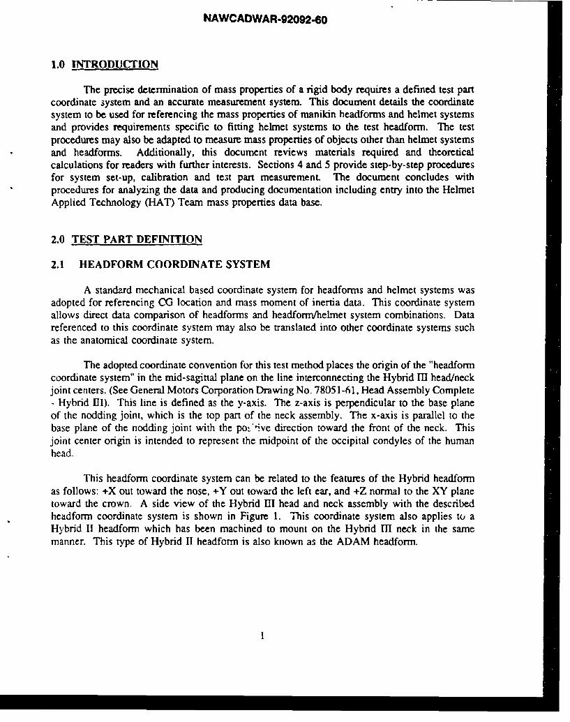
The precise determination of mass properties of a rigid body requires a defined test partcoordinate system and an accurate measurement system. This document details the coordinatesystem to be used for referencing the mass properties of manikin headforms and helmet systemsand provides requirements specific to fitting helmet systems to the test headform. The testprocedures may also be adapted to measure mass properties of objects other than helmet systemsand headforms. Additionally, this document reviews materials required and theoreticalcalculations for readers with further interests. Sections 4 and 5 provide step-by-step proceduresfor system set-up, calibration and test part measurement. The document concludes withprocedures for analyzing the data and producing documentation including entry into the HelmetApplied Technology (HAT) Team mass properties data base.
2.0 TEST PART DEFINITION
2.1 HEADFORM COORDINATE SYSTEM
A standzrd mechanical based coordinate system for headforms and helmet systems wasadopted for referencing CG location and mass moment of inertia data. This coordinate systemallows direct data comparison of headforms and headform/helmet system combinations. Datareferenced to this coordinate system may also be translated into other coordinate systems suchas the anatomical coordinate system.
The adopted coordinate convention for this test method places the origin of the "headformcoordinate system" in the mid-sagittal plane on the line interconnecting the Hybrid MI head/neckjoint centers. (See General Motors Corporation Drawing No. 78051-61, Head Assembly Complete- Hybrid III). This line is defined as the y-axis. The z-axis is perpendicular to the base planeof the nodding joint, which is the top part of the neck assembly. The x-axis is parallel to thebase plane of the nodding joint with the po:'*ive direction toward the front of the neck. Thisjoint center origin is intended to represent the midpoint of the occipital condyles of the humanhead.
This headform coordinate system can be related to the features of the Hybrid headformas follows: +X out toward the nose, +Y out toward the left ear, and +Z normal to the XY planetoward the crown. A side view of the Hybrid III head and neck assembly with the describedheadform coordinate system is shown in Figure 1. This coordinate system also applies to aHybrid II headform which has been machined to mount on the Hybrid III neck in the samemanner. This type of Hybrid II headform is also known as the ADAM headform.

NAWCADWAR-92092-60
+Z
LOAD CELl A•DICCD..EROKLITF1
MOONT
S- NaMDING JOINT
Figure 1Headform Coordinate System
2.2 HELMET FITTING REQUIREMENTS
Helmet fit to the test headform is a critical factor for mass properties determination.Every attempt to simulate the "as-worn" condition of the helmet system must be made. Forexample, helmet liner fitting procedures are required to be conducted prior to weightdetermination since methods used u create some ;u.tom fit liners add weight to the helmetsystem. The same fitting procedures used to fit a helmet to an aircrewman must also be followedwhen fitting to the test headform. Regardless of the headform type, the following checklist iscurrently used in preparing and fitting helmet systems for mass properties testing.
Helmet size shall match that which corresponds to the test headform to be_ use!d,in accordance with the NAVAIR 13-1-6.7 manual for aviation helmets currentlyin USN/USMC fleet use. Prototype helmet size selection, if determined to besubjective, will be on a trial basis, without being excessively loose or tight overthe ears, at the forehead, or in the nape area.
Liners shall be in the as-worn condition, with form-fit procedures performed onthe test headform for which tests will be conducted.
All helmet subcomponents such as communication devices, visor assembly,
oxygen mask, etc., shall be in accordance with NAVAIR 13-1-6.7. Prototypehelmets shall include all of the equal or proposed replacement parts and be notedas such.
2

NAWCADWAR-92092-60
Cables departing from the helmet shell must be detached approximately 2 inches
from the helmet shell to avoid supporting weight which would not be supportedby the head and neck when the helmet system is in use.
Oxygen hose shall be disconnected at the mask.
Earcups shall be checked for symmetric alignment as neither Hybrid series
headform has ears.
Innermost visor shall be in the down position with the edge interfacing properly
with the oxygen mask, minimizing any gap between them.
Nape and chin straps shall be tightened without causing excessive
shell flexation.
3.0 MATERIALS AND THEORETICAL CALCULATIONS
3.1 MEASUREMENT SYSTEM DESCRIPTION
Determining the weight, center of gravity (CG) location and mass moments of inertia(MOI) of headform and helmet systems is accomplished using the Mass Properties System'. rtu,components of this system include:
"* KGR30 Mass Properties Instrument (Space Electronics Inc.)"* Electronic Scale (Sartorius Inc.)"* NAWCACDIV developed: Test Fixtures, Lab Worksheet and Calculations Software
CG location and mass moments of inertia are determined from the same test platformusing the KGR30 mass properties instrument. Weight is determined separately using theelectronic scale.
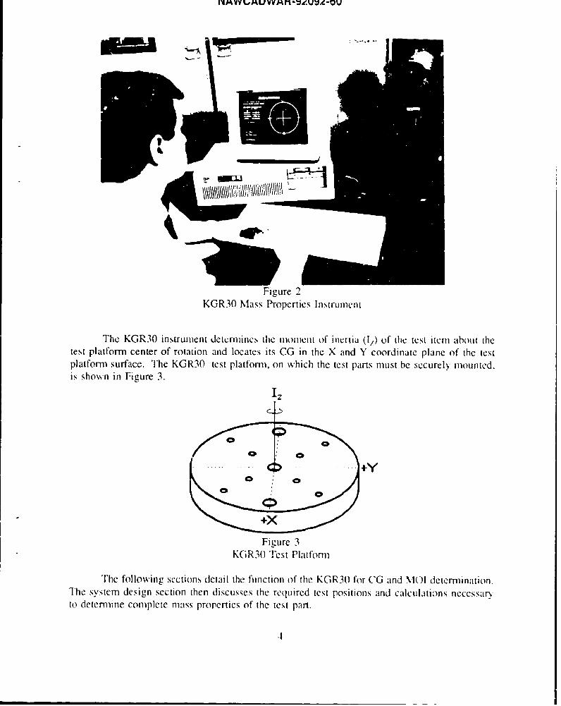
The KGR30 mass properties instrumentP3, shown in Fig-re 2, is a general purposemeasuring instrument capable of testing parts whose combined weight, including test fixtures,does not exceed 300 lbs. The offset moment limit of 33 in-lb is the true limiting factor of thetest platform.
3
I'4AVVL#UWVMf-%NeVV-OU
Figure 2
KGR30 Mass Properties Instrument
The KGR30 instrument detcrmine.s, the moment of ilicrtia (lz) of the tcst item about thetest platform center of rotation and locates its CG in the X and Y coordinate plane of the testplatform surface. The KGR30 test platforn, on which the test parts must be securely mounted.is shown in Figure 3.
Iz
Figure 3KGR3O Test Platform-
The following sections detail the function of the KGR30 for CG and M\10 determination.The system design section then discusses the required test positions and calculations necessaryto determine complete mass properties of the test part.
4

NAWCADWAR-92092-60
3.2 CENTER OF GRAVITY DETERMINATION
The test item CG is located by measuring the offset moment due to the displacement ofthe test item CG from the measurement axis, or center of rotation, of the instrument. Thismoment is sensed by a force transducer which is located at a fixed distance from the pivot axisof the test platform. The measured moment is divided by the weight of the lest part to determinethe location of the CG relative to the pivot axis of the machine. The test platform of theinstrument is rotated at 90 degree intervals through 360 degrees, facilitating measurement of CGin the two axis plane of the test platform surface.
To calibrate the instrument for CG, a cylinder with known weight is placed on acalibration beam at a fixed distance from the pivot axis. The weight is then moved to a secondlocation on the beam. The change in offset moment is the product of the weight (W) times thedistance moved (D) and results in a change in output (C) of the force transducer. The units ofmeasurement are typically:
transducer output ---------- digital counts (C)distance -------------------------- inches (in)weight -------------------------- pounds (lb)
A calibration constant (K) for the machine is calculated by the equation:
K = WD/C (lb-in/count)
When a test item is measured, the offset moment (M) is calculated as:M = CK (lb-in)
where C is the difference in transducer output (counts) between the test item measurement andtare (zero reference) measurement.
3.3 MOMENT OF INERTIA DETERMINATION
Moment of inertia (MOI) of the test item is measured by the inverted torsional pendulummethod. In this method, a low friction gas bearing supports the test part. The upper end of atorsion rod is attached to the underside of the test platform and is fixed at its lower end. Thetest platform is automatically rotated slightly, and released. The resulting period of oscillationis a function of the stiffness of the torsion rod and the moment of inertia of the oscillating mass.The MOI is equal to:
MOI = K (T22 - T1
2)
where K is the machirv, calibration constant, T, is the period of oscillation in arbitrary time units
5

NAWCADWAR-92092-60
of the test platform including fixtures and T2 is the period of the test part, test platform andfixtures.
To calibrate the instrument for MOI, two cylindrical calibrated weights (W, and W2) areplaced at known opposite radial locations (D1 and D2) from the center of the test platform andthe period of oscillation (T,) is measured. The weights are then moved to the center of the testplatform and the new period of oscillation (To) is measured. The change in period is related onlyto the change in MOI (M.) of the oscillating mass, which is:
M. = WID 1 + W2D22
For a torsion pendulum, the period of oscillation squared is directly proportional to the MOI ofthe oscillating mass. Therefore, a calibration constant (K) may be calculated from:
K = M. / (T22 - T12)
3.4 SYSTEM DESIGN
Of paramount importance to the accuracy of the mass properties system is alignment ofthe measurement coordinate system and the test part coordinate system. The alignment isaccomplished using test fixtures developed specifically for mounting manikin headforms. Precisealignment simplifies CG and MOI calculations by eliminating offset distances between origins.To improve measurement accuracy, a rigid neck was also designed to replace the flexible HybridIII neck. This minimizes deflection during testing which can result in erroneous readings. Therigid neck is not representative of the Hybrid III neck with respect to CG and MOI. However,mass properties similarity is not necessary since the neck is part of the fixture assembly and notthe test item. The rigid neck, shown in Figure 4, mates with the nodding joint of the Hybrid 11lneck assembly, enabling attachment of the test headform.
To define the mass properties of our test part the following properties are determined:mass, center of gravity and mass moments about six different axes. These axes include the threepreviously defined headform coordinate axes (I, I:,,I) and those at 45 degrees between thepositive axes ( as shown in Figure 4.
6

NAWCADWAR-92092-60
I,
1. 1,
Figure 4Axes for Mass Moment of Inertia Measurement
Mass moment measurements about each of the six positive headform axes (II,II•,I•,I•)enable calculation of the products of inertia (POI) in each plane. POI calculations are simplifiedand accuracy is maximized by recording moments of inertia about axes precisely 45 degreesbetween the positive headform coordinate axes ( MOI and POI values are then used tocalculate Principal Mass Moments of Inertia (PMMI) and principal axes orientations. This isaccomplished by inserting MOI and POI values determined at the CG into a symmetric inertiatensor matrix. The matrix is then diagonalized to determine Eigen values and vectors whichcorrespond to the PMMI and the associated principal axes orientations.
The six MOI values and 3-dimensional CG location are determined from a series of sixtest positions. For each test position, fixtures are mounted and a Tare measurement recorded.This enables the mass properties system to subtract the properties of the test platform and fixturesfrom the part measurements which follows. Part measurements include the headform and helmetsystem. This measurement sequence yields mass properties of the headform and helmet systemonly, through the use of calculation software. The measurement sequence can be described asa three step process:
1) TARE Measurements (Fixture Only)
2) Part Measurements (Fixture and Test Part)
3) Calculations (Determination of Test Part Only Properties)
7
NAWCADWAR-92092-60
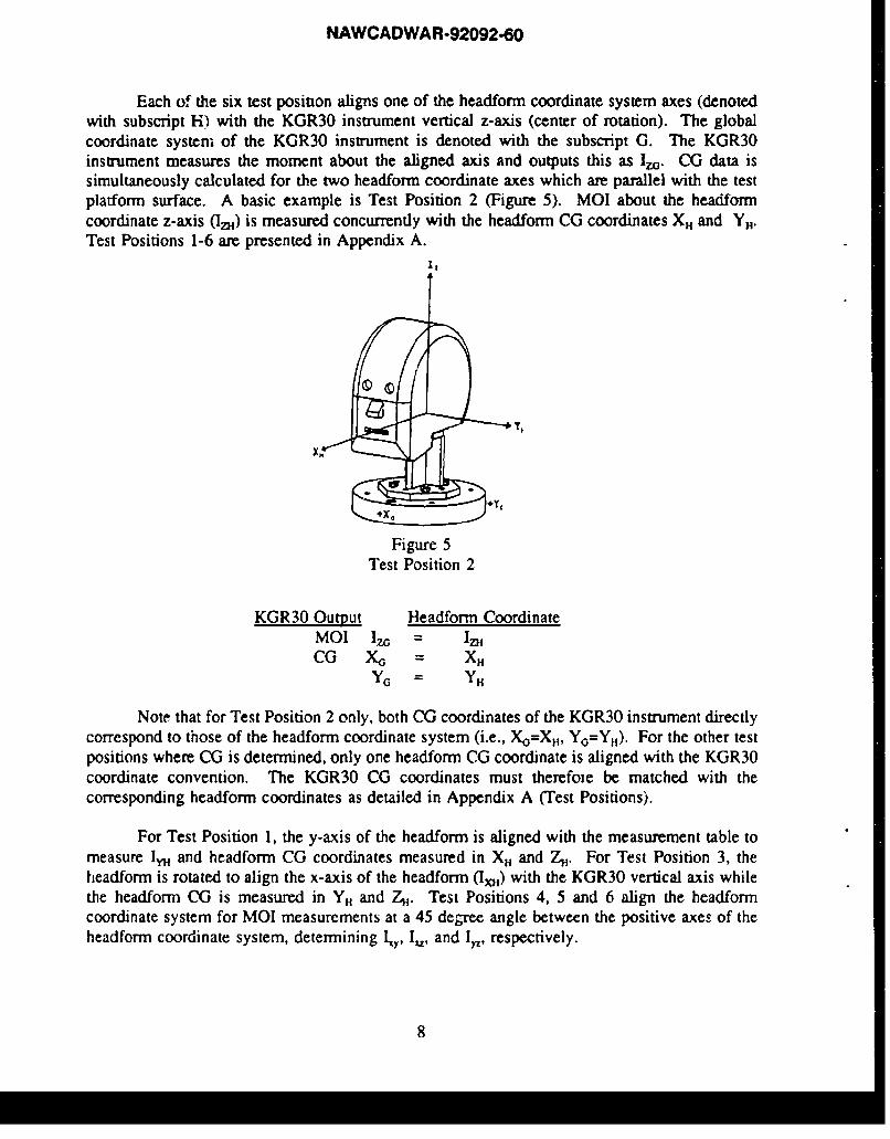
Each of the six test position aligns one of the headform coordinate system axes (denotedwith subscript H) with the KGR30 instrument vertical z-axis (center of rotation). The globalcoordinate system of the KGR30 instrument is denoted with the subscript G. The KGR30instrument measures the moment about the aligned axis and outputs this as Iza. CG data issimultaneously calculated for the two headform coordinate axes which are parallel with the testplatform surface. A basic example is Test Position 2 (Figure 5). MOI about the headformcoordinate z-axis (Iz) is measured concurrently with the headform CG coordinates XH and Y..Test Positions 1-6 are presented in Appendix A.
X T ,
+ +Y
Figure 5Test Position 2
KGR30 Output Headform CoordinateMOI IzG = IzHCO X0 = X.
Note that for Test Position 2 only, both CG coordinates of the KGR30 instrument directlycorrespond to those of the headform coordinate system (i.e., XYO=XH, Y0 =Y11 ). For the other testpositions where CG is determined, only one headform CG coordinate is aligned with the KGR30coordinate convention. The KGR30 CG coordinates must therefoie be matched with thecorresponding headform coordinates as detailed in Appendix A (Test Positions).
For Test Position 1, the y-axis of the headform is aligned with the measurement table tomeasure Ia and headform CG coordinates measured in X. and 7,. For Test Position 3, theheadform is rotated to align the x-axis of the headform (IH) with the KGR30 vertical axis whilethe headform CG is measured in YH and ZH. Test Positions 4, 5 and 6 align the headformcoordinate system for MOI measurements at a 45 degree angle between the positive axes of theheadform coordinate system, determining y, I, and I,., respectively.
8

NAWCADWAR-920.60
4.0 EQUIPMENT SET-UP PROCEDURES
4.1 SET-UP PROCEDURES
Figure 6 is used to locate the parts of the Mass Properties System as referenced in thisprocedure. For example, (*8) refers to the location of the test platform.
9 4
o-zs ra 6I
Figure 6: Mass Properties System
1 Regulator Output 5 Leveling Pads2 Purge Switch 6 Support Screws3 Bearing Pressure Regulator 7 Rotation Control Button4 Computer System 8 Test Platform
9 Data Transfer Switch Box
The following list should be used in preparing the KGR30 mass properties instrument fortesting.
4.1.1 Initial Preparation
1. The system power switch should be in the OFF position.
2. Set the Data Transfer Switch (*9) to A-KGR30.
9

NAWCADWAR-92092-60
4.1.2 Gas Settinas
1. Connect the gas line between the instrument and the source of pressurizednitrogen. Only nitrogen or clean dry air can be used. Normal shop air suppliedby standard compressors contains oil and water that will damage the gas bearingused in this instrument.
2. Set the pressure at the regulator output (*1) on the nitrogen bottle to 75 +/- 5 psi.Place the purge switch (02) in the OFF position and set the bearing pressureregulator (03) to 45 +/- 3 psi.
4.1.3 Computer Operation
1. The computer can now be switched ON (*4) and will display a menu system.Select the mass properties option from the menu and sub-menu. The KGR30main menu will be displayed as shown below. Descriptions of the main menuselections are presented in Appendix B.
>>>>> MAIN MENU <<<<<
OPERATOR: NAMEDATE: MONTH, DAY,YEARTIME: HOURS, MINUTES, SECONDS
TEST PART ID: TEST PART NAME, POSITION #, RUN #TEST SERIAL NUMBER: xxxx
SELECT A FUNCTION KEY OPTION BELOW:FI: Update Test InformationF2: CG/MOI Part MeasurementF3: CG/MOI Tare MeasurementF4: CG/MOI CalibrationFS: System UtilitiesF6: Calculations
FIO: Quit
2. Select F5 (System Utilities) followed by F2 to Purge Data From Disk. This willprevent using old data as part of any new calculations.
4.1.4 Leveling the Instrument
I. Table support screws (*6) must be raised and the gas turned ON (*2) duringleveling. Place the carpenters level on the KGR30 test platform and if necessary
10
NAWCADWAR-92092-60
(it rarely should be) adjust the leveling pads (OS) at floor level until the bubble iscentered.
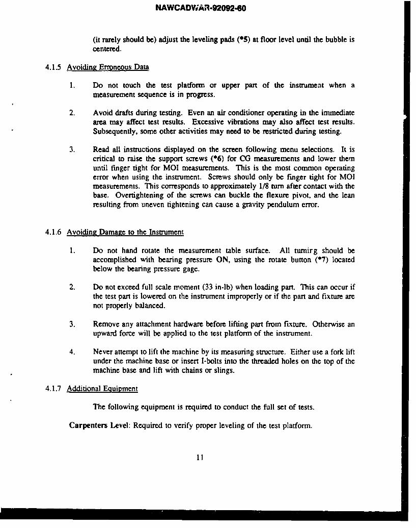
4.1.5 Avoiding Erroneous Data
1. Do not touch the test platform or upper part of the instrument when ameasurement sequence is in progress.
2. Avoid drafts during testing. Even an air conditioner operating in the immediatearea may affect test results. Excessive vibrations may also affect test results.Subsequently, some other activities may need to be restricted during testing.
3. Read all instructions displayed on the screen following menu selections. It iscritical to raise the support screws (*6) for CG measurements and lower themuntil finger tight for MOI measurements. This is the most common operatingerror when using the instrument. Screws should only be finger tight for MOImeasurements. This corresponds to approximately 1/8 turn after contact with thebase. Overtightening of the screws can buckle the flexure pivot, and the leanresulting from uneven tightening can cause a gravity pendulum error.
4.1.6 Avoiding Damage to the Instrument
1. Do not hand rotate the measurement table surface. All turnirg should beaccomplished with bearing pressure ON, using the rotate button (*7) locatedbelow the bearing pressure gage.
2. Do not exceed full scale moment (33 in-lb) when loading part. This can occur ifthe test part is lowered on the instrument improperly or if the part and fixture arenot properly balanced.
3. Remove any attachment hardware before lifting part from fixture. Otherwise anupward force will be applied to the test platform of the instrument.
4. Never attempt to lift the machine by its measuring structure. Either use a fork liftunder the machine base or insert I-bolts into the threaded holes on the top of themachine base and lift with chains or slings.
4.1.7 Additional Eiuipment
The following equipment is required to conduct the full set of tests.
Carpenters Level: Required to verify proper leveling of the test platform.
11

NAWCADWAR-92092-60
Adjustable Wrenches: Two are required to assemble the test fixtures for each testposition.
Allen Wrenches: English and Metric size sets are required for securing fixtures to the !estplatform, assembly of the headforms and other minor modifications.
Screwdrivers: Phillips head and standard slot head screwdrivers are required for assemblyof test fixtures.
Rubber Mallet/ 1/4" dia. shaft: Helpful for inserting and removing the connecting pinused to mount the headform to the neck assembly.
Glue stick / Flashlight: Useful for correcting any problems encountered with the washerswhen mounting the headform.
Calculator: Helpful for calculation of CG heights, total weights, and mean values ofother measured mass properties data.
4.2 CALIBRATION PROCEDURE
The choice must occasionally be made whether or not to calibrate the instrument. If theinstrument has been moved, or if it has not been calibrated for one week or more, then it isrecommended that the calibration procedure be followed. If the instrument has been calibratedearlier in the day, the same calibration values at that time can be used without the need forrepeating the calibration procedure.
1. A system calibration is initiated by selecting F4 from the main menu. CG and MOIcalibrations are separate options but both must be conducted to fully calibrate the KGR30instrument. Once CG or MOI calibration has been selected, the computer will providestep by step instructions for locating the appropriate calibration weights and I-Beam. Therequired positions of the weights on the test platform (*8) are referenced with letters A-Efor each placement position on the I-Beam. At numerous points in the sequence theoperator may select F9 to abort the sequence and return to the main menu. A typicalcalibration set-up is shown in Figure 7.
2. Select F1 for CG calibration. Position I-Beam and calibration weights per screeninstruction, select F10 to initiate CG calibration sequence. Follow screen instructions formovement of weights.
3. Select F2 for MOI calibration. Position I-Beam and calibration weights per screeninstruction, then select F10 to initiate MOI calibration sequence. Follow screeninstructions for repositioning of weights.
12

NAWCADWAR-92092-60
nwmm
lit
E
BD
co- I-BA
Figure 7Typical Calibration Set-up
4.3 SYSTEM CHECK PROCEDURE
Following calibration a system check should be performed using a calibrated weight. Thefollowing procedure can be. used for measurement of any calibrated weight which can beaccurately positioned on the test platform. Results for comparison are provided based on usingule S7623-A calibrated cylinder.
1. Select F1 to update test information.
2. A set of Tare measurements for the bare test platform is initiated by selecting F3. SelectCG Taiv- and conduct measurements, followed by MOI Tare and measurements. Raiseand lower the support screws as prompted on the screen.
3. Place the S7623-A calibrated cylinder in one of the holes on the KGR30 test platform.
4. Select F2 to record part measurements (CG and MOI). Raise and lower support screwsas prompted on the computer screen.
5. Select Calculations F6, followed by FI0 for both CG and MOI calculations. Enter theweight as 0.9877 lb. and CG height as 1.0 inch, then select Fi0 to continue.
6. Compare resultant data with values in Table 1 to verify proper system function. Recordresults and file them with all previous system checks. If problems are encountered,consult Appendix D (Problem/Solution Index).
13
NAWCADWAR-92092-60
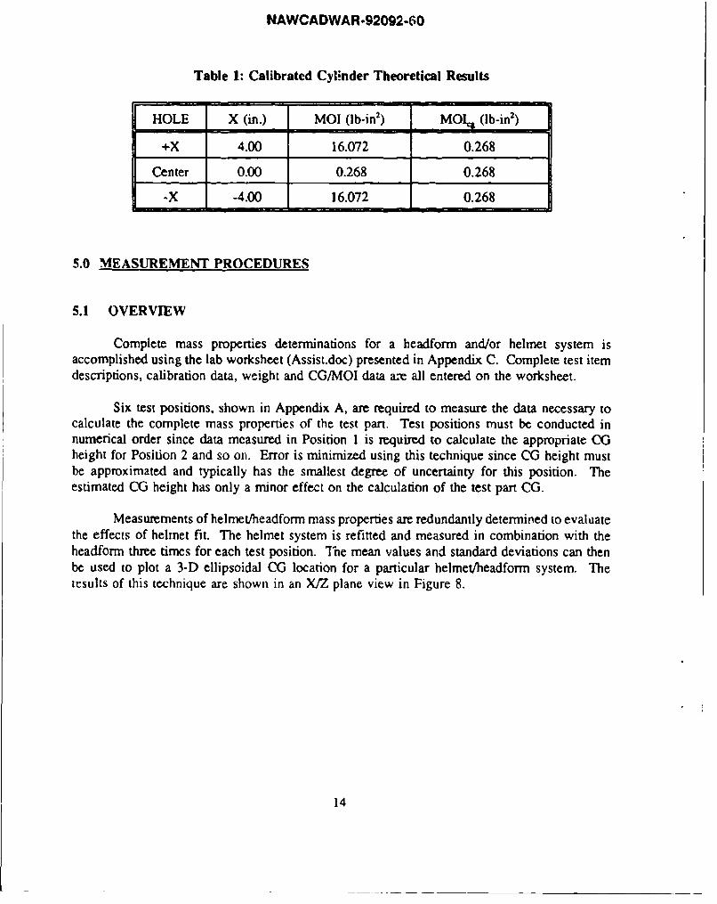
Table 1: Calibrated Cylinder Theoretical Results
HOLE X (in.) MOI (lb-in2) MOIk (lb-in2)
+X 4.00 16.072 0.268
Center 0.00 0.268 0.268
-X -4.00 16.072 0.268
5.0 MEASUREMENT PROCEDURES
5.1 OVERVIEW
Complete mass properties determinations for a headform and/or helmet system isaccomplished using the lab worksheet (Assist.doc) presented in Appendix C. Complete test itemdescriptions, calibration data, weight and CG/MOI data are all entered on the worksheet.
Six test positions, shown in Appendix A, are required to measure the data necessary tocalculate the complete mass properties of the test part. Test positions must be conducted innumerical order since data measured in Position 1 is required to calculate the appropriate CGheight for Position 2 and so on. Error is minimized using this technique since CG height mustbe approximated and typically has the smallest degree of uncertainty for this position. Theestimated CG height has only a minor effect on the calculation of the test part CG.
Measurements of helmet/headform mass properties are redundantly determinied to evaluatethe effects of helmet fit. The helmet system is refitted and measured in combination with theheadform three times for each test position. "Ihe mean values and standard deviations can thenbe used to plot a 3-D ellipsoidal CG location for a particular helmet/headform system. Theicsults of this technique are shown in an X/Z plane view in Figure 8.
14

NAWCADWAR-92092-60
Figure 8: X/Z Plane View of CG Ellipsoid
If any problems arise during this test procedure, refer to Appendix D (Problems/Solutions
Index).
5.2 WEIGHT DETERMINATION
1. Obtain a lab worksheet (Assist.doc) and record all pretest information includingspecifics on the test items.
2. Turn the electronic scale ON, shown in Figure 9, and allow 15 minutes for warmup. Measure the calibrated cylinder ($7623-A) to assure accuracy. The weight ofthe cylinder is certified at 0.98777 (lb.).
3. Record weights of all components as listed on the lab worksheet. Custom fittingprocedures of liner systems must be performed prior to weight determination.
Figure 9: Electronic Scale
15
NAWCADWAR-92092-60
5.3 CGIMOI MEASUREMENT SEQUENCE
The following test procedures of Section 5.3 are repeated for each of the six test positionsusing the appropriate fixture and location on the test platform as specified in Appendix A.
5.3.1 Measuring Fixture Properties
Fixture mass properties are measured using the TARE option, so these properties may besubtracted from the combined fixture and test part measurements. Weight and CG heightinformation are not required for TARE measurements.
1. Select F1 and update test information with appropriate test position number. Forexample, "TARE, Test Position #".
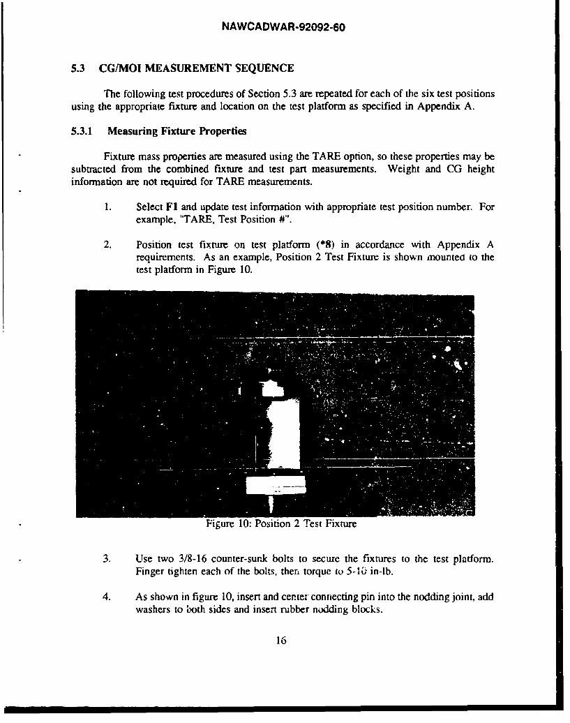
2. Position test fixture on test platform (*8) in accordance with Appendix Arequirements. As an example, Position 2 Test Fixture is shown mounted to thetest platform in Figure 10.
Figure 10: Position 2 Test Fixture
3. Use two 3/8-16 counter-surk bolts to secure the fixtures to the test platform.Finger tighten each of the bolts, then torque to 5-10 in-lb.
4. As shown in figure 10, insert and center connecting pin into the nodding joint, addwashers to both sides and insert rubber nodding blocks.
16

NAWCADWAR-92092-60
5. Select TARE measurement F3 from main menu. Perform both CG and MOITares separately, raising and lowering support screws as prompted on thecomputer screen.
5.3.2 Measuring Headform/Helmet Properties
For each test position, headform only mass properties are measured first by followingsteps 1, 3-9. Headform/Helmet mass properties are then determined by following steps 2-10.
1. Mount the test headform as shown in Appendix A (Test Positions) and record dataon the bare headform only by following steps 3 through 9. Make sure theconnecting pin is inserted in the same direction and orientation as for the TARE.The typical procedure is to insert the pin in from the direction of the left ear.Figure 11 shows a Test Headform mounted in Test Position 2.
Figur. 11Test Headform Mounted in Test Position 2
2. Mount the helmet system and oxygen mask using proper fit techniques as perSection 2.2 (Helmet Fitting Require:ments). Measurements of the helmet/headformsystem will be repeated three times to obtain redundant data as discussed in theoverview. Figure 12 shows a helmet system fit for testing.
17

NAWCADWAR-92092-60
Figure 12
lielmetlHeadform Mounted in Test Position 2
3. Select Fl and update test information to include test position number, helmetsystem, headform type and run number.
4. Select F2 from the main menu for part measurement.
5. Raise support screws and select CG part measurement.
6. Lowkcr support screws and select MOI pan measurement.
7. Select F6 to perform CG/MOI calculations for this test position. Enter thecorresponding weight and calculated CG height for this test position from the labworksheet.
8. Record resultant CG and MOI values as specified on the lab worksheet.
9. Save all computer printouts of the data by stapling them to the lab wvorkshect.
10. The helmet system and oxygen mask are now removed and refitted to the testheadform for a new set of measurements. The test cycle (steps 2 through 9) arerepeated to obtain three sets of measurements for each helmet system type in eachtest position.
1 1. Advance to the next test position. Repeat fixture, headforn and headform/helnetmeasurement procedures (5.3.1 and 5.3.2).
lx
NAWCADWAR-92092-60
6.0 DATA ANALYSIS PROCEDURES
The resultant values from the lab worksheet are entered into a computation program fordetermination of the maguitudes of the principal mass moments of inertia and orientation of theprincipal axes. An example of the calculations and program output are found in Appendix C(Sample Data and Calculations). The program is accessible through any computer terminal linkedto the HATLAB local area network by using the following procedure.
1. Type net name * from the dos prompt.
2. Use the login:thornton and the appropriate password.
3. Change your drive to "N" by typing N: at the dos prompt.
4. Switch to the mass properties data base directory by typing N:cd thorntonrnpdb.The program is run by typing N:\thomton\rnpdb:pmcrev2.exe.
Instructions for entering the appropriate data will be displayed. Output files are namedby the date :h- data was processed and a two digit counter (YYMMDDxx.dat). The results of theprogram calculations are stored in this file and can be printed by typing Hatt%lprYYMMDDxx.dat. Save this printout by stapling it to the appropriate lab worksheet.
7.0 DOCUMENTATION REQUIREMENTS
Results of all mass properties testing are entered into the Headform/Helmet MassProperties Data Base in accordance with the document guidelines of Reference 4. This enablesthe development of a more comprehensive data base to be used in the comparison of varioushelmet systems and the evaluation of head/neck safety.
19
NAWCADWAR-92092-60
8.0 REFERENCES
1. Thornton Jeffrey M., "An Improved Method for Determining the Mass Properties ofHelmets and Helmet Mounted Systems", Naval Air Warfare Center - Aircraft Division,Report No. NAWCADWAR-92053-60.
2. Boynton, Richard and Kurt Wiener (1988) Space Electronics, Inc. SAWE paper no.1827,"A New High Accuracy Instrument for Measuring Moment of Inertia and Center ofGravity".
3. Boynton, Richard and Kurt Wiener (1989) Space Electronics, Inc., "Operating andInstruction Manual Mass Properties Instrument Model KGR30".
4. Zaborowski, David J. and Jeffrey M. Thornton,"Headform/Helmet Mass Properties DataBase", Naval Air Wai fare Center - Aircraft Division, Document Draft 1/13/92.
20

NAWCADWAR-92092-60
Appendix A
TEST POSITIONS

NAWCADWAR-92092-60
Appendix A - Test Positions 1-6
TEST POSITION 1
KGR30 Output Headform CoordMOI I, =C I xu
CG Xv XvYAG =Z
A-1

NAWCADWAR-92092-60
TEST POSITION 2
KGR30 Output Headform CoordMOI I zG I zilYCG XG XH
+= Y
A-2

NAWCADWAR-92092-60
TEST POSITION 3
i0
KGR30 Output Headform CoordMOI I zr. I,
CG X =Y
Y = ZR
-xc+Y

NAWCADWAR-92092-60
TEST POSITION 4
0I
KGR30 Output Headform Coord
-'C'
+A-4
NAWCADWAR-92092-60
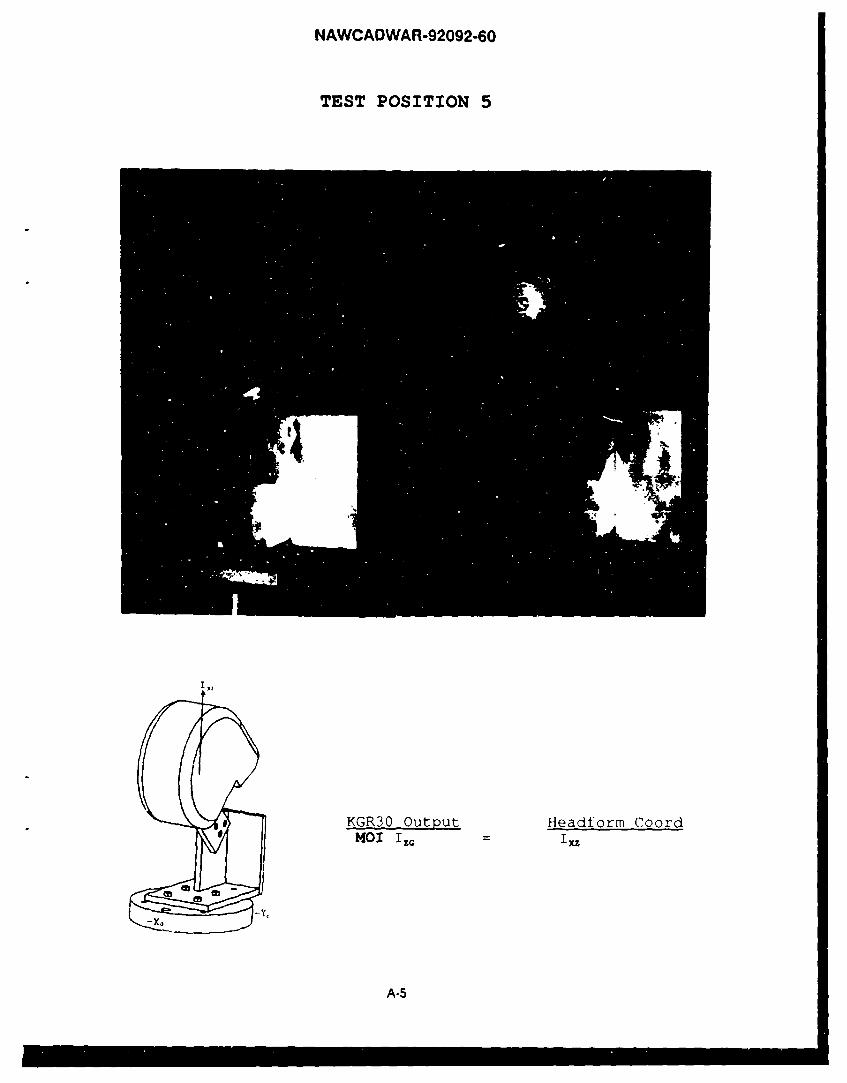
TEST POSITION 5
SKGR30 Output Headform Coord*o MI I ix
-Yc
A-5

NAWCADWAR-92092..60
TEST POSITIONJ
KGR30 Output Headforrr CoordMOI iz IYZ
A-6
NAWCADWAR-92092-60
Appendix B
KGR30 MAIN MENU DESCRIPTIONS
NAWCADWAR-92092-60
MAIN MENU OPERATING DESCRIPTIONS
Selections from the main menu are discussed following each function key listed below:
FI: Update Test Information
Allows the operator to enter a new Operator name and test part information. Test informationmust be updated previous to every set of measurements (CG and MOI). This information isprinted on the data printout and is the only record of the data once new measurements arerecorded. Information to be entered should include test part name, test position #, and run #.This will ensure that the data may be properly identified at a later date.
F2: CGfMOI Part Measurement
Allows the operator to select CG or MOI Test Part Measurement function. Support screws areto be raised for CG and lowered for MOI.
F3: CG/MOI Tare Measurements
Allows the operator to select CG or MOI Tare Measurement function. Tare measurements onthe fixtures only are subtracted from the part measurements (fixtures and test item) in order toobtain test item only data.
F4: CG/MOI Calibration
Allows the operator to recalibrate the KGR30. Instructions are displayed on the screen forpositioning I-Beam and weights.
F5: System Utilities
Allows the operator to select one of the following functions from the utilities menu.
FI: Update VariablesF2: Purge Data From DiskF3: DiagnosticsF4: Return to Main Menu
Update Utilities (Utilities Fl)
This function provides access to system constants through a Password which has been given toan authorized customer representative. Contact manufacturer prior to changing any constants.
Purge Data From Disk (Utilities F2)
B-i

NAWCADWAR-92092-60
This function allows measurement data to be purged. It may be useful, for example, to purgeold CG data to prevent calculating old CGI results when only MOI measurements through thecenter of rotation are currently required.
Diagnostics (Utilities F3)
This function provides manual access to options which are useful in debugging system problems:
Read LVDTToggle motor ON/OFFClamp/unclamp the torsion rodEnable/disable the Optron monitoring functionInitiate CG sequenceInitiate MOI sequence
F6: Calculations
Allows the operator to perform calculations with existing Calibration, Tare and Part Measurementdata. Tare data may be used for successive measurements provided the fixturing has not beenchanged or moved.
B-2

NAWCADWAR-92-090
Appendix C
SAMPLE DATA AND CALCULATIONS

NAWCADWAR-92092-60
Helmet Advanced Technolog' LaboratoryMass Properties Data Sheet (ASSIST.DOC)
TESTS CONDUCTED BY:________________________ DATE:______ / _
TEST ITEM (including model # and size): // &6-' - &-6/P '"" ""/-'ie
Specify head type and instrumentation included: //G!, ' -/ . fo"A...d•,-, 2.i 44 ,:,.v, ,A,'/o,' 'Th<,,c.•. 5+,.... L,,Ac' ,/•!4,b.st,'- 6'~v;.' 7•• -.
Specify oxygen mask (model # and size): A"Chf- /Z/P 1
KGR30 system Calibration
Calibration Date (MM/DD/YY): / ?2
MOI Calibration Constant: Y,•' 3 7 4/5- (lb-inl/sec2 )
CG Calibration Constant 3- co93 3 (lb-in/ct)
weight Results
M, = , - 3 3 9 (lb.)
M2 = e2Xo mug (lb.)
M3 =* MALAMIN (lb.)
M, = M, + M, +M, = 1 _.777 7 (lb.)
Center-of-Gravity Results Mass Homentb of Inertia Results
X,= 0. C (in.) 1',2 = 3 . -9-7 (ibTin2)
YX- -___,_7 (in.) /f /3', 6;74( (lb*in')
I.. = / 72, Z0 (lb*in')
I = /4//. 374• (lb~in2 )
I(ib*in')
C-1

NAWCADWAR-92092-60
POSITION I. (IV) :
1. Align fixture assembly in accordance withPosition 1 requirements and TARE the assembly.
2. Mount Headform and Helmet and record part data.
3. For calculations (F6) use Weight=M.,CG height = 8.625 in. (Fixture design height)
X (X-output) Z (Y-output) 1, (lb'in') I,, (lb*in')2- 7- 2.-, &, z7 2 *7.:? 6l7 /,(,. 4%2 9
2. 2- 2- 1.z 9 3 / 172.2- 16,4, 9//
3. I0 7g& 2, 7- 67 2-7•70 16b/ 7
x- d.2-0 2-.31 1". 2- 7_1,.- -6_7(inches) 21- ((lb*in'F) (lb-in')
POSITION 2 (Iz):
1. Align fixture assembly in accordance with
Position 2 requirements, then TARE the assembly.
2. Mount Headform and Helemt and record part data.
3. For calculations (F6), Weight=M,,CG height = 5.375 in. + Z= "7
X(X-output) Y (Y-output) I, (lb'in') I,.. (b*In')
2. 3. /tl (/. ,, . ( ?7. 3 •"23. /,Z -7/ v,, ~ l1 5 . / & •
x, /./Z12 (o-3 - s .o7Z i,. /L;-.If -7 5I S.32V(inches) (inches) flb'in') (lb'in')
C-2

NAWCADWAR-92092-60
POSITION 3 Ix:
1. Align fixture assembly in accordance withPosition 3 requirements, then TARE the assembly.
2. Mount Headform and Helmet and record data.
3. For calculations (F6) use Weight= M.,CG height = 8.625 in. + (X,+X,)/2 = ?, (in.)
Y (X-output) z Y-output) I, (Ib*in') (I, (b in')0. D S5-(' 2 , 2 "7•gq 2 0/. 5"ý-3 /2 5_-5
2. .OL) • 2. 23 7• l &- /23. 0. 0 ?s .3>-2 "/f ,2e3. /2 3 , < "
Y'. __ V z,. 2,5- 1. 1__99-et7(i-nches) (inches) (ib*in') IR-
Center of Gravity (CG) Results
X,= (X, + X,)/2 le /, (in.)
Y, (Y, + Y,)/2 = -7, e,7 (in.)
Z,= (Z, + Z,)/2 = __ __ __0 (in.)
C-3

NAWCADWAR-92092-60
POSITION 4 (Ixy) :
1. Align fixture assembly in accordance with
Position 4 requirements, then TARE the assembly.
2. Mount Headform and Helmet and record part data.
3. For calculations (F6) use Weight= M,,CG height = 8.625 in.+ (X,*sin45 + Y,*sin45) = . - (in.)
Z (Y-OUtput) L, (lb* in2) I... (ib*in')
1. 2.-1937 2 3 /, 5-•2 1.5-1 e
2. 2. 2?co2 2- 35".60 15-3 2
""__2_.__ I= 2- 3'/ -- I / .2o 26'!9
(inches) (lb*in') (lb*in2)
POSITION 5 (Ixz)
1. Align fixture assembly in accordance with
Position 5 requirements, then TARE the assembly.
2. Mount Headform and Hemet and record part data.
3. For calculations (F6) use Weight= M,,CG height = 8.625in.+(X,*sin45 + Z,*sin45) //oo57 (in.)
Y (Y-output) I,, (lb in 2 ) I2SC, (lb* in')
I. C. T2S -z) . 7 3
2.
3. O,7 - /5- 3. /Q'" / 41/,•-
y,= _____ _ I-= 6 -2 . .6 Io- /Y/° 376(inches) (lb*in') (lb*inz)
C4
NAWCADWAR-92092-60
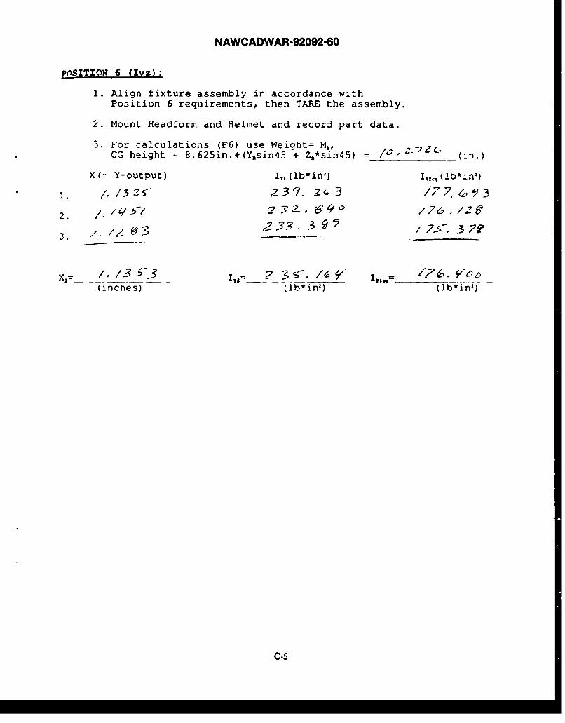
p(nSITION 6 (Iyz):
1. Align fixture assembly in accordance withPosition 6 requirements, then TARE the assembly.
2. Mount Headform and Helmet and record part data.
3. For calculations (F6) use Weight= M,,CG height = 8.625in.+(Y~sin45 + Z,*sin45) - (in.)
X (- Y-output) I,, (lb* in') I,,ý, U b * in2)
1. ,1325- 2.':.2(, 3 /7 4,•, ý?3
2. / /l.¢i . 4-0 176 ,1/2e
I 32733- .3~ /7-57, 37?93. _ _ _
X, '/ /3-'- .2'. , 3 s-. /6* __I______-__"_°Z
(inches) (lb*in') (lb*in')
C-5

NAWCADWAR-92092-60
Output File Name : 04139204.datSystem description : HGU-66/P (Large) w/CATS-EYES & CEEDS on Hybrid III
Weight of Head/Helmet or Helmet system: 14.77400 lb.Equivalent mass of system - 6.70134 kg.
CENTER OF GRAVITY VALUES (in.) w.r.t. pivot pin originX - 1.10400 Y - 0.07000 Z - 2.26000 ir.or - 2.80416 - 0.17780 - 5.74040 cm.
MASS MOI ENTERED VALUES (About the CG):Ixx - 123.57600 lb*in**2Iyy - 183.67599 lb*in**2Izz - 166.!2899 lb*in**2Ixy at 45 deg.- 152.28799 lb*.Ln**2Ixz at 45 deg.- 141.37601 lb*in**2Iyz at 45 deg.- 176.39999 lb*iii**2
Inertia Matrix at CS w.r.t. origin coordinate system:Ixx -Pxy -Pxz 123.57600 -1.33800 -3.57649
-Pyx Iyy -Pyz -1.33800 183.67599 1.39749-Pzx -Pzy Izz -3.57649 1.39749 166.32899
PRINCIPAL MASS MOMENTS OF INERTIA:Ix Iy Iz
123.25433 183.83185 166.49481 (lb(mass)*in**2)360.69147 537.96552 487.23041 (kg*cm**2)
0.31898 0.47576 0.43089 (lbs(force)*in*sec**2)
ROTATION COSINE MATRIX (ORIGIN to PRINCIPAL axes:)i j k
0.99642 -0.02717 -0.080030.02017 0.99600 -0.087000.08208 0.08508 0.99299
Rotation Matrix in degrees (Row Vectors):4.84880 91.56344 94.59754
88.85100 5.12418 94.9981085.29823 85.12589 6.78964
ROTATION ANGLES from ORIGIN to principle axes (deg):RC'LL(x) = 5.007PITCH(y)- -4.591YAW(z) - 1.562
The Determinant of matrix A - 0.37725E+07The tolerance is set at : 0.10000E-05
The first .heck is valid. Product of the eigen values
The second check is valid. Sum of the eigen values
C-6

NAWCADWAR-92092-60
Appendix D
PROBLEM/SOLUTION INDEX

NAWCADWAR-92092-60
PROBLEM/SOLUTION INDEX
PROBLEM SOLUTION
1. If a C prompt (C>) should appear at 1. Change directories by typingthe system start up ..... CD\KGR. When the C prompt
appears again, tyre KGR. Anintroduction menu will be displayed.Press the spacebar, and the main menuwill be displayed.
2. If uncertain which test fixture to 2. See Appendix A which has figures foruse ...... each test position.
3. CG variation seems large between test 3. Repeat one of the sets ofpositions.... measurements and verify correct Tare
and Part measurement serial numbersare used in the calculations.
4. Scale reading of certified weight 4. Check leveling of scale and allowvaries ........... proper warm up time...
5. Incorrect data was typed in for test part 5. Immediately correct the computerI.1 .......... printout of the data.
6. Incorrect Tare or Part measurement 6. Repeat only the incorrect measurementdata was used for calculations ........ and perform calculations again. Tare
and Part measurements are stored untiloverwritten by the next measurement.
7. Outside disturbance affects Tare or 7. Same as 6.Part measurements...
8. If nothing happens when CG/MOI Tare 8. Select F9 to abort. Check all cableor Part measurement selected ..... connections. Review diagnostics
options discussed in Appendix B.
D-1
NAWCADWAR-92092-60
PROBLEM SOLUTION
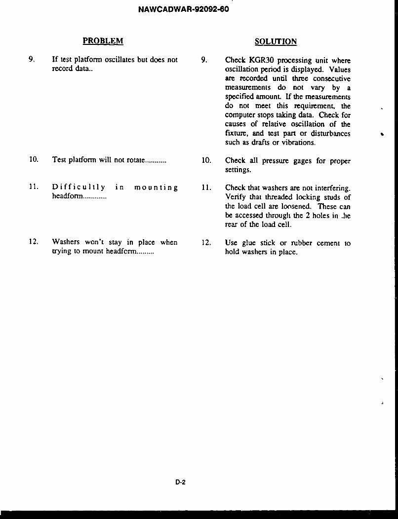
9. If test platform oscillates but does not 9. Check KGR30 processing unit whererecord data.. oscillation period is displayed. Values
are recorded until three consecutivemeasurements do not vary by aspecified amounL If the measurementsdo not meet this requirement, thecomputer stops taking data. Check forcauses of relative oscillation of thefixture, and test part or disturbancessuch as drafts or vibrations.
10. Test platform will not rotate ........... 10. Check all pressure gages for propersettings.
11. D i f f i c u I t I y i n mounting 11. Check that washers are not interfering.headform ............ Verify that threaded locking studs of
the load cell are loosened. These canbe accessed through the 2 holes in .herear of the load cell.
12. Washers won't stay in place when 12. Use glue stick or rubber cement totrying to mount headfcrm ......... hold washers in place.
D-2
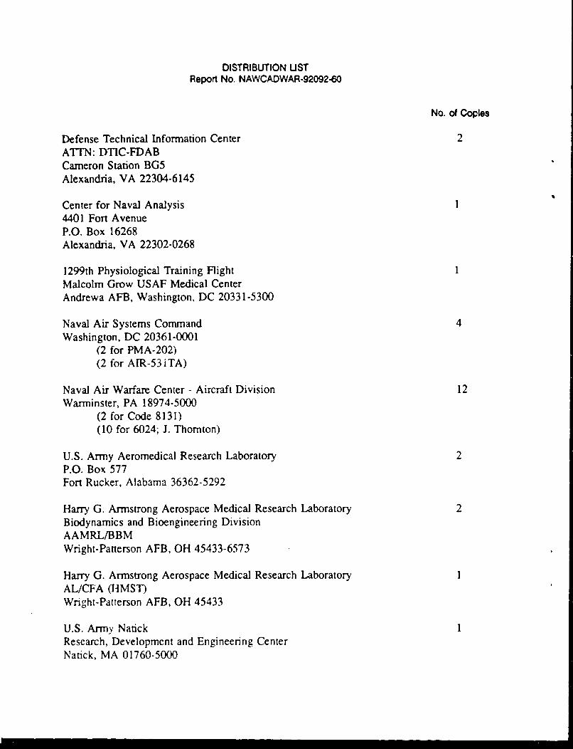
DISTRIBUTION USTReport No. NAWCADWAR-92092-60
No. of Copies
Defense Technical Information Center 2ATTN: DTIC-FDABCameron Station BG5Alexandria, VA 22304-6145
Center for Naval Analysis4401 Fort AvenueP.O. Box 16268Alexandria, VA 22302-0268
1299th Physiological Training FlightMalcolm Grow USAF Medical CenterAndrewa AFB, Washington, DC 20331-5300
Naval Air Systems Command 4Washington, DC 20361-0001
(2 for PMA-202)(2 for AIR-53iTA)
Naval Air Warfare Center - Aircraft Division 12Warminster, PA 18974-5000
(2 for Code 8131)(10 for 6024; J. Thornton)
U.S. Army Aeromedical Research Laboratory 2P.O. Box 577Fort Rucker, Alabama 36362-5292
Harry G. Armstrong Aerospace Medical Research Laboratory 2Biodynamics and Bioengineering DivisionAAMRL/BBMWright-Patterson AFB, OH 45433-6573
Harry G. Armstrong Aerospace Medical Research LaboratoryAL/CFA (HMST)Wright-Patterson AFB, OH 45433
U.S. Army NatckResearch, Development and Engineering CenterNatick, MA 01760-5000

I DAiC: 69