Embed Size (px)
Citation preview
AIS-142
I
AUTOMOTIVE INDUSTRY STANDARD
Evaluation of Tyres with Regard to Rolling Sound Emissions and/or to
Adhesion on Wet Surfaces and/or to Rolling Resistance
PRINTED BY THE AUTOMOTIVE RESEARCH ASSOCIATION OF INDIA
P.B. NO. 832, PUNE 411 004
ON BEHALF OF AUTOMOTIVE INDUSTRY STANDARDS COMMITTEE
UNDER
CENTRAL MOTOR VEHICLE RULES – TECHNICAL STANDING COMMITTEE
SET-UP BY MINISTRY OF ROAD TRANSPORT & HIGHWAYS
(DEPARTMENT OF ROAD TRANSPORT & HIGHWAYS) GOVERNMENT OF INDIA
February 2019

AIS-142
II
Status chart of the standard to be used by the purchaser for updating the record
Sr. No.
Corrigenda. Amendment Revision Date Remark Misc.
General remarks :
AIS-142
III
INTRODUCTION The Government of India felt the need for a permanent agency to expedite the publication of standards and development of test facilities in parallel when the work on the preparation of the standards is going on, as the development of improved safety critical parts can be undertaken only after the publication of the standard and commissioning of test facilities. To this end, the erstwhile Ministry of Surface Transport (MOST) has constituted a permanent Automotive Industry Standards Committee (AISC) vide order No. RT-11028/11/97-MVL dated September 15, 1997. The standards prepared by AISC will be approved by the permanent CMVR Technical Standing Committee (CTSC). After approval, the Automotive Research Association of India, (ARAI), Pune, being the Secretariat of the AIS Committee, has published this standard. For better dissemination of this information ARAI may publish this standard on their web site. Based on the discussions in the 52nd meeting of AISC it was agreed to form a new AIS standard in line with UN R 117. AIS-142 is prepared in line with Revision 4 of UN R 117. The standard was approved in the 58th meeting of AISC and adopted in 52nd meeting of CMVR-TSC.
The AISC panel and the Automotive Industry Standards Committee (AISC) responsible for preparation of this standard are given in Annex G and Annex H respectively.
*****
AIS-142
IV
Evaluation of Tyres with Regard to Rolling Sound Emissions and/or to Adhesion on Wet Surfaces and/or to Rolling Resistance
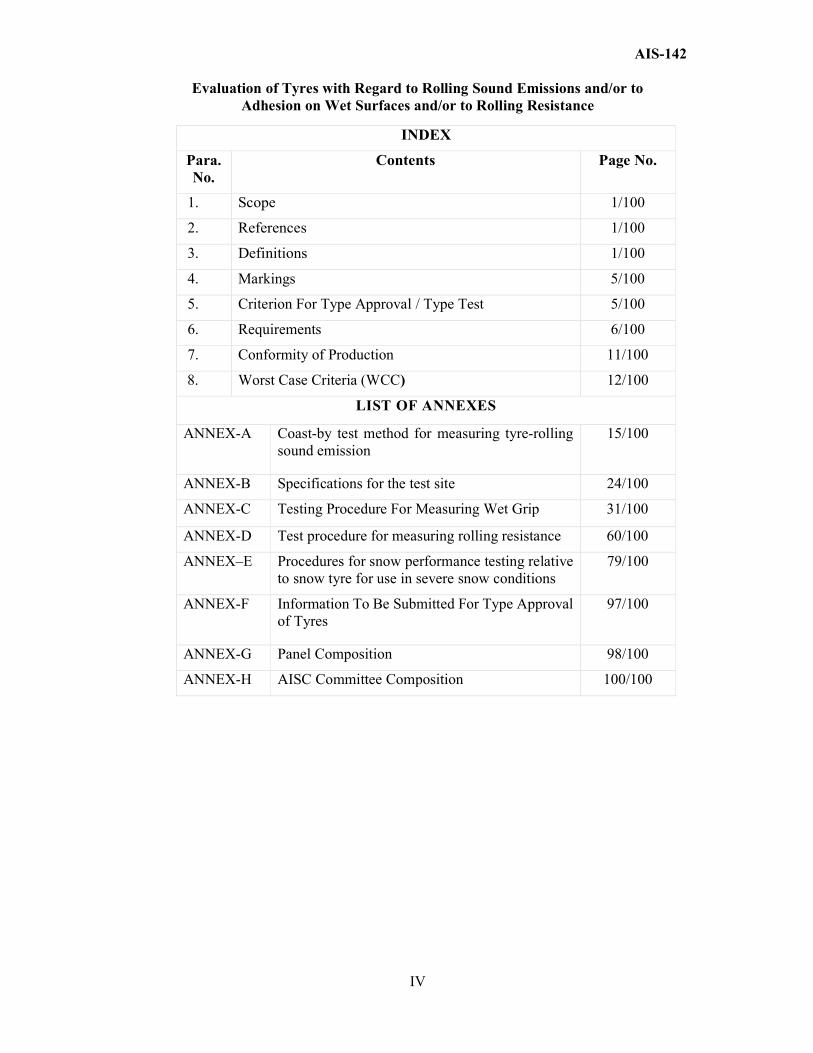
INDEX
Para. No.
Contents Page No.
1. Scope 1/100
2. References 1/100
3. Definitions 1/100
4. Markings 5/100
5. Criterion For Type Approval / Type Test 5/100
6. Requirements 6/100
7. Conformity of Production 11/100
8. Worst Case Criteria (WCC)
12/100
LIST OF ANNEXES
ANNEX-A
Coast-by test method for measuring tyre-rolling sound emission
15/100
ANNEX-B Specifications for the test site 24/100
ANNEX-C Testing Procedure For Measuring Wet Grip 31/100
ANNEX-D Test procedure for measuring rolling resistance 60/100
ANNEX–E Procedures for snow performance testing relative to snow tyre for use in severe snow conditions
79/100
ANNEX-F
Information To Be Submitted For Type Approval of Tyres
97/100
ANNEX-G Panel Composition 98/100
ANNEX-H AISC Committee Composition 100/100
AIS-142
1/100
Evaluation of Tyres with Regard to Rolling Sound Emissions and/or to Adhesion on Wet Surfaces and/or to Rolling Resistance
1.0 SCOPE
1.1 This Standard applies to new pneumatic tyres of Classes C1, C2 and C3
with regard to their sound emissions, rolling resistance and to adhesion performance on wet surfaces (wet adhesion). It does not, however, apply to:
1.1.1 Tyres designed as "Temporary use spare tyres" and marked "Temporary use only";
1.1.2 Tyres having a nominal rim diameter code ≤ 10 (or ≤ 254 mm) or ≥ 25 (or ≥ 635 mm);
1.1.3 Tyres designed for competitions;
1.1.4. Tyres intended to be fitted to road vehicles of categories other than M, N and T;
1.1.5. Tyres fitted with additional devices to improve traction properties (e.g. studded tyres);
1.1.6. Tyres with a speed rating less than 80 km/h (speed symbol F);
1.1.7. Professional off-road tyres.
2.0 REFERENCE
UN R 117
3.0 DEFINITIONS
For the purpose of this Standard, in addition to the definitions contained in IS: 15633 and IS: 15636, the following definitions apply.
3.1 "Type of tyre" means, in relation to this Standard, a range of tyres consisting of a list of tyre size designations, brand names and trade descriptions, which do not differ in such essential characteristics as:
(a) The manufacturer's name; (b) The tyre class (see paragraph 3.4. below); (c) The tyre structure; (d) The category of use: normal tyre, snow tyre and special use tyre; (e) For Class C1 tyres:
(i) In case of tyres submitted for approval of rolling sound emission levels, whether normal or reinforced (or extra load);
(ii) In case of tyres submitted for approval of performance adhesion on wet surfaces, whether normal tyres or snow tyres with a speed category of Q or below excluding H (≤ 160 km/h) or speed category R and above including H (> 160 km/h);
AIS-142
2/100
(f) For Classes C2 and C3 tyres: (i) In case of tyres submitted for approval of rolling sound
emission levels at stage 1, whether M+S marked or not; (ii) In case of tyres submitted for approval of rolling sound
emission levels at stage 2, whether traction tyre or not; (g) The tread pattern.
3.2. "Brand name" or "Trade description" means the identification of
the tyre as given by the tyre manufacturer. The brand name may be the same as that of the manufacturer and the Trade description may coincide with the trade mark.
3.3. "Rolling sound emission" means the sound emitted from the contact between the tyres in motion and the road surface.
3.4. "Tyre class" means one of the following groupings:
3.4.1. Class C1 tyres: Tyres conforming to Standard IS 15633;
3.4.2. Class C2 tyres: Tyres conforming to Standard IS 15636 and identified by a load capacity index in single formation lower or equal to 121 and a speed category symbol higher or equal to "N" and/or tyres marked with LT/C;
3.4.3. Class C3 tyres: Tyres conforming to Standard IS 15636 and identified by:
(a) A load capacity index in single formation higher or equal to 122 and /or tyres not marked with LT/C; or
(b) A load capacity index in single formation lower or equal to 121 and a speed category symbol lower or equal to "M" and /or tyres not marked with LT/C.
3.5 "Representative tyre size" means the tyre size which is submitted to the test described in Annex A to this Standard with regard to rolling sound emissions, or Annex C for adhesion on wet surfaces or Annex D for rolling resistance to assess the conformity for the type approval of the type of tyre, or Annex E for use in severe snow conditions.
3.6. "Temporary-use spare tyre" means a tyre different from a tyre intended to be fitted to any vehicle for normal driving conditions; but intended only for temporary use under restricted driving conditions.
3.7. "Tyres designed for competition" means tyres intended to be fitted to vehicles involved in motor sport competition and not intended for non-competitive on-road use.
3.8. "Normal tyre" means a tyre intended for normal on-road use.
3.9. "Reinforced tyre" or "extra load tyre" of Class C1 means a pneumatic-tyre structure designed to carry more load at a higher inflation pressure than the load carried by the corresponding standard version tyre at the standard inflation pressure as specified in ISO 4000-1:2010.
AIS-142
3/100
3.10. "Traction tyre" means a tyre in class C2 or C3 bearing the inscription TRACTION and intended to be fitted primarily to the drive axle(s) of a vehicle to maximize force transmission in various circumstances.
3.11. "Snow tyre" means a tyre whose tread pattern, tread compound or structure is primarily designed to achieve in snow conditions a performance better than that of a normal tyre with regard to its ability to initiate or maintain vehicle motion.
3.11.1. "Snow tyre for use in severe snow conditions" means a snow tyre whose tread pattern, tread compound or structure is specifically designed to be used in severe snow conditions and that fulfils the requirements of paragraph 6.4. of this Standard.
3.12. "Special use tyre" means a tyre intended for mixed use both on- and off-road or for other special duty. These tyres are primarily designed to initiate and maintain the vehicle in motion in off-road conditions
3.13. "Professional off-road tyre" is a special use tyre primarily used for service in severe off-road conditions
3.14. "Tread depth" means the depth of the principal grooves.
3.14.1. "Principal grooves" means the wide circumferential grooves positioned in the central zone of the tyre tread, which, in the case of passenger and light truck (commercial) tyres, have the tread wear indicators located in the base.
3.15. "Void to fill ratio" means the ratio between the area of voids in a reference surface and the area of this reference surface calculated from the mould drawing.
3.16. "Standard reference test tyre" (SRTT) means a tyre that is produced, controlled and stored in accordance with the ASTM (American Society for Testing and Materials) standards:
(a) E1136-93 (2003) for the size P195/75R14 (b) F2872 (2011) for the size 225/75 R 16 C (c) F2871 (2011) for the size 245/70 R 19.5 (d) F2870 (2011) for the size 315/70 R 22.5
3.17. Wet Grip or Snow Grip measurements – Specific definitions
3.17.1. "Adhesion on wet surfaces" means the relative braking performance, on a wet surface, of a test vehicle equipped with the candidate tyre in comparison to that of the same test vehicle equipped with a reference tyre (SRTT).
3.17.2. "Candidate tyre" means a tyre, representative of the type that is submitted for approval in accordance with this Standard.
3.17.3. "Control tyre" means a normal production tyre that is used to establish the wet grip or snow grip performance of tyre sizes unable to be fitted to the same vehicle as the standard reference test tyre – see paragraph 4.1.7. of Annex C and paragraph 3.4.3. of Annex E to this Standard.
AIS-142
4/100
3.17.4. "Wet grip index ("G")" means the ratio between the performance of the candidate tyre and the performance of the standard reference test tyre.
3.17.5. "Snow grip index ("SG")" means the ratio between the performance of the candidate tyre and the performance of the standard reference test tyre.
3.17.6. "Peak brake force coefficient ("pbfc")" means the maximum value of the ratio of braking force to vertical load on the tyre prior to wheel lock-up.
3.17.7. "Mean fully developed deceleration ("mfdd")" means the average deceleration calculated on the basis of the measured distance recorded when decelerating a vehicle between two specified speeds.
3.17.8. "Coupling (hitch) height" means the height when measured perpendicularly from the centre of the articulation point of the trailer towing coupling or hitch to the ground, when the towing vehicle and trailer are coupled together. The vehicle and trailer shall be standing on level pavement surface in its test mode complete with the appropriate tyre(s) to be used in the particular test.
3.18. Rolling resistance measurement - Specific definitions
3.18.1. Rolling resistance Fr Loss of energy (or energy consumed) per unit of distance travelled.
3.18.2. Rolling resistance coefficient Cr Ratio of the rolling resistance to the load on the tyre.
3.18.3. New test tyre A tyre which has not been previously used in a rolling deflected test that raises its temperature above that generated in rolling resistance tests, and which has not previously been exposed to a temperature above 40 °C.,
3.18.4. Laboratory control tyre Tyre used by an individual laboratory to control machine behaviour as a function of time.
3.18.5. Capped inflation Process of inflating the tyre and allowing the inflation pressure to build up, as the tyre is warmed up while running.
3.18.6. Parasitic loss Loss of energy (or energy consumed) per unit distance excluding internal tyre losses, attributable to aerodynamic loss of the different rotating elements of the test equipment, bearing friction and other sources of systematic loss which may be inherent in the measurement.
3.18.7. Skim test reading Type of parasitic loss measurement, in which the tyre is kept rolling without slippage, while reducing the tyre load to a level at which energy loss within the tyre itself is virtually zero.
AIS-142
5/100
3.18.8. Inertia or moment of inertia.
Ratio of the torque applied to a rotating body to the rotational acceleration of this body.
3.18.9. Measurement reproducibility σm
Capability of a machine to measure rolling resistance.
4.0 MARKINGS
4.1 All tyres constituting the type of tyre shall be marked as prescribed by either Standard IS 15633 or IS 15636, as applicable.
4.2 In particular tyres shall bear
4.2.1 The manufacturer's name or trade mark;
4.2.2 The trade description (see paragraph 3.2. of this Standard). However, the trade description is not required when it coincides with the trade mark;
4.2.3 The tyre size designation;
4.2.4 The inscription "REINFORCED" (or alternatively "EXTRA LOAD") if the tyre is classified as reinforced;
4.2.5 The inscription "TRACTION" if the tyre is classified as "traction tyre";
4.2.6 The "Alpine" symbol ("3-peak-mountain with snowflake" conforming to the symbol described in Annex E, Appendix 1) shall be added if the snow tyre is classified as "snow tyre for use in severe snow conditions".
4.2.7 The inscription "MPT" (or alternatively "ML" or "ET") and /or "POR" if the tyre is classified in the category of use "special". ET means Extra Tread, ML stands for Mining and Logging, MPT means Multi-Purpose Truck and POR means Professional Off-Road.
4.3 Tyres shall provide adequate space for the approval mark.
4.4 The approval mark shall be moulded into or onto the sidewall of the tyre, shall be clearly legible and shall be located in the lower area of the tyre on atleast one of the sidewalls.
4.4.1 However, in the case of tyres identified by the tyre to rim fitment configuration symbol "A", the marking may be located anywhere on the outside sidewall of the tyre.
5.0 CRITERION FOR TYPE APPROVAL / TYPE TEST
5.1 Tyres(s) shall meet the test requirements tested as per requirements given in Annex A to this Standard with regard to rolling sound emissions, or Annex C for adhesion on wet surfaces or Annex D for rolling resistance to assess the conformity for the type approval of the type of tyre, or Annex E for use in severe snow conditions.
AIS-142
6/100
5.2 Type Approval Procedure.
5.2.1 Application for type approval to be submitted by the manufacturer.
5.2.2 The application for type approval shall contain at least the technical information as specified in Annex F. Note - For type approval of tyre belonging to one family of tyre, brand
of the tyre to be selected for type approval shall be left to certifying authority. Worst case selection shall be made at the discretion of the certifying authority based on the criteria specified in 8.0.
5.2.3 Changes in the technical specifications of already type approved tyres.
5.2.3.1 Every functional modification in technical specification declared in accordance with 5.2.1 shall be intimated to the certifying authority.
5.2.3.2 The certifying authority may then consider, whether:
a) Tyre with modification complies with specified requirements, or
b) Any further verification is required
For considering whether any further verification is required or not (criteria for extension of type approval) specified in 5.2.5 shall be used.
5.2.3.3 In case of 5.2.3.2 (b), checks for those parameters which are affected by the modifications, only need to be carried out.
5.2.4 In the event of 5.2.3.2 (a) or in the case of 5.2.3.2 (b) after successful compliance to the requirements, a certificate of compliance shall be validated for the modified version, as applicable.
5.2.5 Criteria for extension of Type approval
5.2.5.1 In case the changes cause the tyre to be outside the approved family / range of tyres, the verification shall be carried out for establishing compliance of the changed parameters to the requirements specified in this standard.
6.0 REQUIREMENTS
6.1 Rolling sound emission limits, as measured by the method described in Annex A to this Standard.
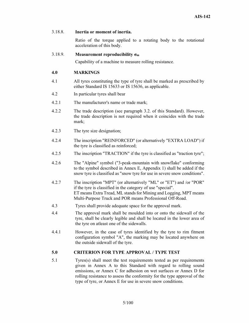
6.1.1 For Class C1 tyres, the rolling sound emission value shall not exceed the values pertinent to the applicable stage given below. These values refer to the nominal section width as given below:
Stage 1
Nominal section width Limit dB(A)
145 and lower 72 Over 145 up to 165 73 Over 165 up to 185 74 Over 185 up to 215 75
Over 215 76 The above limits shall be increased by 1 dB(A) for extra load tyres or reinforced tyres and by 2 dB(A) for "special use tyres".
AIS-142
7/100
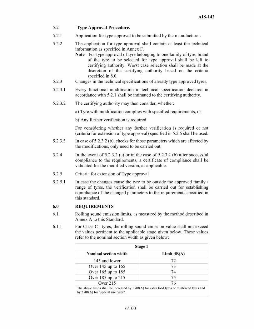
Stage 2
Nominal section width Limit dB(A)
185 and lower 70
Over 185 up to 245 71
Over 245 up to 275 72
Over 275 74 The above limits shall be increased by 1 dB(A) for "snow tyre for use in severe snow conditions", extra load tyres or reinforced tyres, or any combination of these classifications.
6.1.2 For Class C2 tyres, the rolling sound emission value with reference to its category of use (see paragraph 3.1., subparagraph (d) above) shall not exceed the values pertinent to the applicable stage given below:
Stage 2
Category of use
Limit dB(A)
Other Traction tyres
Normal tyre 72 73 Snow tyre 72 73
Snow tyre for use in severe snow conditions
73 75
Special use tyre
74 75
Stage 1
Category of use Limit dB(A)
Normal tyre 75 Snow tyre 77
Special use tyre 78
6.1.3 For Class C3 tyres, the rolling sound emission value with reference to its category of use (see paragraph 3.1., subparagraph (d) above) shall not exceed the values pertinent to the applicable stage given below:
Stage 1
Category of use Limit dB(A)
Normal tyre 76 Snow tyre 78
Special use tyre 79
AIS-142
8/100
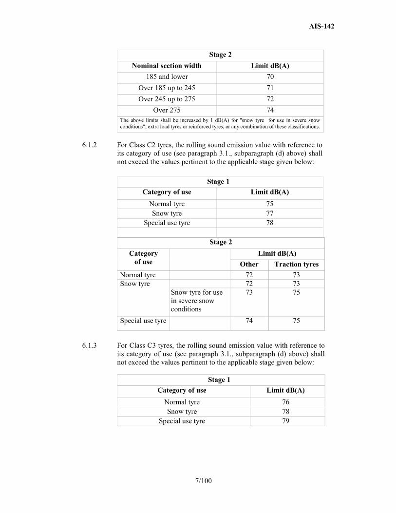
Stage 2 Category of use Limit dB(A)
Other Traction tyres
Normal tyre 73 75 Snow tyre 73 75
Snow tyre for use in severe snow conditions
74 76
Special use tyre 75 77
6.2. The wet grip performance will be based on a procedure that compares either peak brake force coefficient ("pbfc") or mean fully developed deceleration ("mfdd") against values achieved by a standard reference test tyre (SRTT). The relative performance shall be indicated by a wet grip index (G).
6.2.1 For Class C1 tyres, tested in accordance with either procedure given in Annex C, Part (A) to this Standard, the tyre shall meet the following requirements:
Category of use Wet grip index (G)
Normal tyre ≥ 1.1 Snow tyre ≥ 1.1
"Snow tyre for use in severe snow conditions" and with a speed symbol ("R" and above, including "H") indicating a maximum permissible speed greater than 160 km/h
≥ 1.0
"Snow tyre for use in severe snow conditions" and with a speed symbol ("Q" or below excluding "H") indicating a maximum permissible speed not greater than 160 km/h
≥ 0.9
Special use tyre Not defined
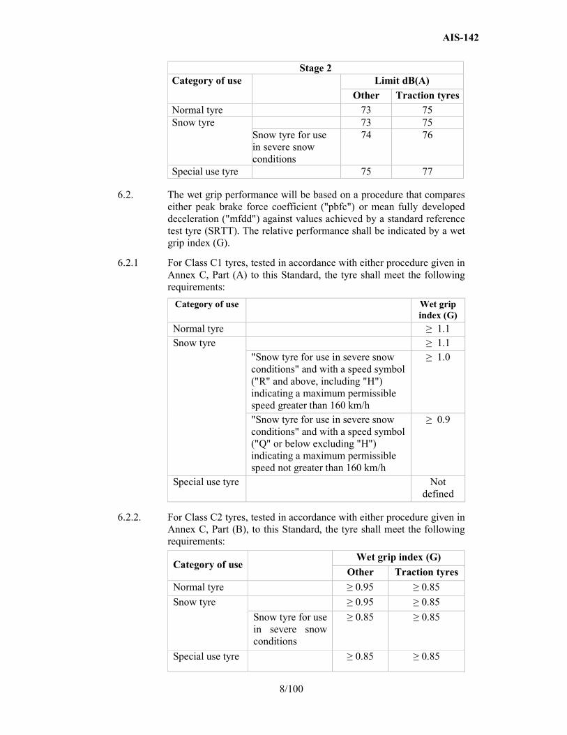
6.2.2. For Class C2 tyres, tested in accordance with either procedure given in Annex C, Part (B), to this Standard, the tyre shall meet the following requirements:
Category of use Wet grip index (G)
Other Traction tyres
Normal tyre ≥ 0.95 ≥ 0.85
Snow tyre ≥ 0.95 ≥ 0.85
Snow tyre for use in severe snow conditions
≥ 0.85 ≥ 0.85
Special use tyre ≥ 0.85 ≥ 0.85
AIS-142
9/100
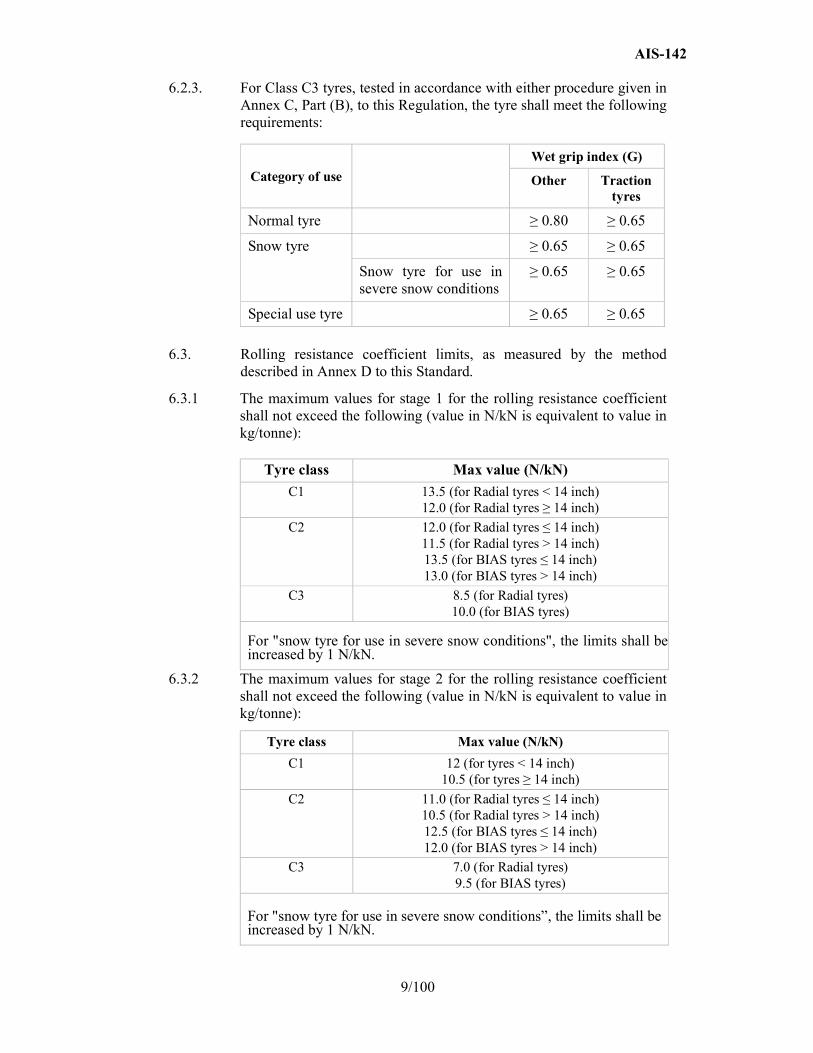
6.2.3. For Class C3 tyres, tested in accordance with either procedure given in Annex C, Part (B), to this Regulation, the tyre shall meet the following requirements:
Category of use
Wet grip index (G)
Other Traction tyres
Normal tyre ≥ 0.80 ≥ 0.65
Snow tyre ≥ 0.65 ≥ 0.65
Snow tyre for use in severe snow conditions
≥ 0.65 ≥ 0.65
Special use tyre ≥ 0.65 ≥ 0.65
6.3. Rolling resistance coefficient limits, as measured by the method described in Annex D to this Standard.
6.3.1 The maximum values for stage 1 for the rolling resistance coefficient shall not exceed the following (value in N/kN is equivalent to value in kg/tonne):
Tyre class Max value (N/kN)
C1 13.5 (for Radial tyres < 14 inch) 12.0 (for Radial tyres ≥ 14 inch)
C2 12.0 (for Radial tyres ≤ 14 inch) 11.5 (for Radial tyres > 14 inch) 13.5 (for BIAS tyres ≤ 14 inch) 13.0 (for BIAS tyres > 14 inch)
C3 8.5 (for Radial tyres) 10.0 (for BIAS tyres)
For "snow tyre for use in severe snow conditions", the limits shall be increased by 1 N/kN.
6.3.2 The maximum values for stage 2 for the rolling resistance coefficient shall not exceed the following (value in N/kN is equivalent to value in kg/tonne):
Tyre class Max value (N/kN)
C1 12 (for tyres < 14 inch) 10.5 (for tyres ≥ 14 inch)
C2 11.0 (for Radial tyres ≤ 14 inch) 10.5 (for Radial tyres > 14 inch) 12.5 (for BIAS tyres ≤ 14 inch) 12.0 (for BIAS tyres > 14 inch)
C3 7.0 (for Radial tyres) 9.5 (for BIAS tyres)
For "snow tyre for use in severe snow conditions”, the limits shall be increased by 1 N/kN.
AIS-142
10/100
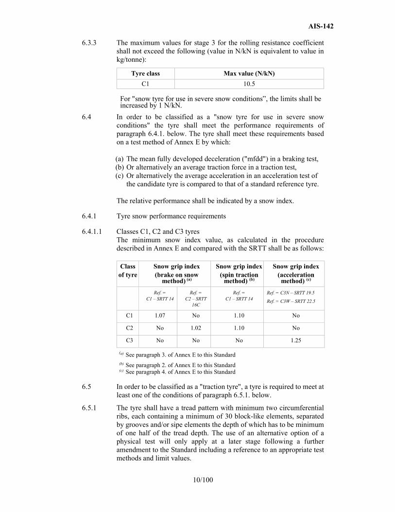
6.3.3 The maximum values for stage 3 for the rolling resistance coefficient shall not exceed the following (value in N/kN is equivalent to value in kg/tonne):
Tyre class Max value (N/kN)
C1 10.5
For "snow tyre for use in severe snow conditions”, the limits shall be increased by 1 N/kN.
6.4 In order to be classified as a "snow tyre for use in severe snow conditions" the tyre shall meet the performance requirements of paragraph 6.4.1. below. The tyre shall meet these requirements based on a test method of Annex E by which: (a) The mean fully developed deceleration ("mfdd") in a braking test, (b) Or alternatively an average traction force in a traction test, (c) Or alternatively the average acceleration in an acceleration test of
the candidate tyre is compared to that of a standard reference tyre.
The relative performance shall be indicated by a snow index.
6.4.1 Tyre snow performance requirements
6.4.1.1 Classes C1, C2 and C3 tyres The minimum snow index value, as calculated in the procedure described in Annex E and compared with the SRTT shall be as follows:
Class of tyre
Snow grip index (brake on snow
method) (a)
Snow grip index (spin traction
method) (b)
Snow grip index (acceleration method) (c)
Ref. = C1 – SRTT 14
Ref. = C2 – SRTT
16C
Ref. = C1 – SRTT 14
Ref. = C3N – SRTT 19.5
Ref. = C3W – SRTT 22.5
C1 1.07 No 1.10 No
C2 No 1.02 1.10 No
C3 No No No 1.25
(a) See paragraph 3. of Annex E to this Standard (b) See paragraph 2. of Annex E to this Standard (c) See paragraph 4. of Annex E to this Standard
6.5 In order to be classified as a "traction tyre", a tyre is required to meet at least one of the conditions of paragraph 6.5.1. below.
6.5.1 The tyre shall have a tread pattern with minimum two circumferential ribs, each containing a minimum of 30 block-like elements, separated by grooves and/or sipe elements the depth of which has to be minimum of one half of the tread depth. The use of an alternative option of a physical test will only apply at a later stage following a further amendment to the Standard including a reference to an appropriate test methods and limit values.

AIS-142
11/100
6.6 In order to be classified as a "special use tyre" a tyre shall have a block tread pattern in which the blocks are larger and more widely spaced than for normal tyres and have the following characteristics:
For C1 tyres: a tread depth ≥ 11 mm and void to fill ratio ≥ 35 per cent
For C2 tyres: a tread depth ≥ 11 mm and void to fill ratio ≥ 35 per cent
For C3 tyres: a tread depth ≥ 16 mm and void to fill ratio ≥ 35 per cent
6.7 In order to be classified as a "professional off-road tyre", a tyre shall have all of the following characteristics:
(a) For C1 and C2 tyres:
(i) A tread depth ≥ 11 mm; (ii) A void-to-fill ratio ≥ 35 per cent; (iii) A maximum speed rating of ≤ Q. (b) For C3 tyres:
(i) A tread depth ≥ 16 mm; (ii) A void-to-fill ratio ≥ 35 per cent; (iii) A maximum speed rating of ≤ K.
7.0 CONFORMITY OF PRODUCTION
7.1 Periodic testing and approval based on worst case criteria specified in 8.0 of each type of tyre as per the approved family of tyres shall be carried out. The approval marking shall be made only on the tyres of that approved family and the same shall not get extended to other families of tyres, unless tyres from out of that have undergone the same testing and type approval for that family of tyre.
7.2 The tyres approved under this standard shall be so manufactured as to conform to requirements set forth in in Annex A to this Standard with regard to rolling sound emissions, or Annex C for adhesion on wet surfaces or Annex D for rolling resistance or Annex E for use in severe snow conditions.
7.3 The production and quality assurance system shall meet all the requirements laid out by the certifying authority.
7.4 Production shall be deemed to conform to the requirements of this Standard if the levels measured comply with the limits prescribed in paragraph 6.1. of this Regulation, with an additional allowance of +1 dB(A) for possible mass production variations.
7.5 Production shall be deemed to conform to the requirements of this Standard if the levels measured comply with the limits prescribed in paragraph 6.3. of this Regulation, with an additional allowance of + 0.3 N/kN for possible mass production variations.
AIS-142
12/100
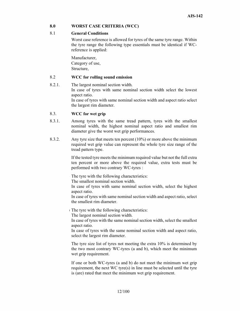
8.0 WORST CASE CRITERIA (WCC)
8.1 General Conditions
Worst case reference is allowed for tyres of the same tyre range. Within the tyre range the following type essentials must be identical if WC-reference is applied:
Manufacturer, Category of use, Structure,
8.2 WCC for rolling sound emission
8.2.1. The largest nominal section width. In case of tyres with same nominal section width select the lowest aspect ratio. In case of tyres with same nominal section width and aspect ratio select the largest rim diameter.
8.3. WCC for wet grip
8.3.1. Among tyres with the same tread pattern, tyres with the smallest nominal width, the highest nominal aspect ratio and smallest rim diameter give the worst wet grip performances.
8.3.2. Any tyre size that meets ten percent (10%) or more above the minimum required wet grip value can represent the whole tyre size range of the tread pattern type.
If the tested tyre meets the minimum required value but not the full extra ten percent or more above the required value, extra tests must be performed with two contrary WC-tyres :
(a) The tyre with the following characteristics: The smallest nominal section width.
In case of tyres with same nominal section width, select the highest aspect ratio. In case of tyres with same nominal section width and aspect ratio, select the smallest rim diameter.
(b) The tyre with the following characteristics: The largest nominal section width.
In case of tyres with the same nominal section width, select the smallest aspect ratio. In case of tyres with the same nominal section width and aspect ratio, select the largest rim diameter.
The tyre size list of tyres not meeting the extra 10% is determined by the two most contrary WC-tyres (a and b), which meet the minimum wet grip requirement.
If one or both WC-tyres (a and b) do not meet the minimum wet grip requirement, the next WC tyre(s) in line must be selected until the tyre is (are) rated that meet the minimum wet grip requirement.

AIS-142
13/100
8.4. WCC for rolling resistance
8.4.1. The standard tyre with the lowest load index. Standard tyres prove worse rolling resistance coefficient results versus reinforced tyres. Select the standard tyre in the case of tyres with the same load index but differing in standard and reinforced indication. Run flat tyres prove worse rolling resistance coefficient results versus standard tyres. Select the Run flat version in case of tyres with the same load index in both standard as in run flat version. If another tyre is tested other than the worst case tyre, a relativized limit value must be calculated and met. To verify if a lower load index (LI-lowest) meets the requirements of the regulation, the limit value for the tested tyre (LI-candidate) is calculated by the formula: Calculated limit value = (RRC-limit value R117 - 0.3# N/Kn) – 0.06* x (LI-candidate – LI-lowest) # the limit value of the regulation will be increased by a safety margin
of 0.3N/kN * the slope of rolling resistance coefficient versus load index is fixed on
0.06. The tyres with a lower load index can be added to the tyre size list if the RRC value of the tested candidate tyre is equal or less than the calculated limit value.
The calculation must be presented in the information document or test report of the application package.
Verification calculation. To be able to make a verification calculation on the rolling
resistance coefficient the following information must be presented in the rolling resistance test report:
Force method: - Lm-skim : applied skim load (see 4.6.1. of Annex D) - rl–skim : distance from tyre axis to test drum outer surface at skim
load - Ft-skim : spindle Force at skim load - Ft-test load : spindle Force at test load Torque method: - Lm-skim : applied skim load (see 4.6.1. of Annex D) - Tt-skim : Torque at skim load - Tt-test load : Torque at test load
AIS-142
14/100
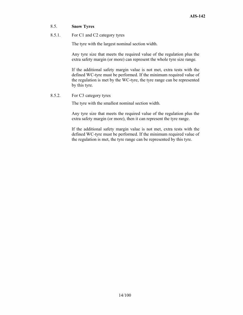
8.5. Snow Tyres
8.5.1. For C1 and C2 category tyres
The tyre with the largest nominal section width. Any tyre size that meets the required value of the regulation plus the extra safety margin (or more) can represent the whole tyre size range. If the additional safety margin value is not met, extra tests with the defined WC-tyre must be performed. If the minimum required value of the regulation is met by the WC-tyre, the tyre range can be represented by this tyre.
8.5.2. For C3 category tyres
The tyre with the smallest nominal section width. Any tyre size that meets the required value of the regulation plus the extra safety margin (or more), then it can represent the tyre range. If the additional safety margin value is not met, extra tests with the defined WC-tyre must be performed. If the minimum required value of the regulation is met, the tyre range can be represented by this tyre.
AIS-142
15/100
ANNEX - A (See 3.5)
COAST-BY TEST METHOD FOR MEASURING TYRE-ROLLING SOUND EMISSION
0.0 Introduction
The presented method contains specifications on measuring instruments, measurement conditions and the measurement method, in order to obtain the sound level of a set of tyres mounted on a test vehicle rolling on a specified road surface. The maximum sound pressure level is to be recorded, when the test vehicle is coasting, by remote-field microphones; the final result for a reference speed is obtained from a linear regression analysis. Such test results cannot be related to tyre rolling sound measured during acceleration under power or deceleration under braking.
1.0 Measuring instruments
1.1 Acoustic measurements
The sound level meter or the equivalent measuring system, including the windscreen recommended by the manufacturer shall meet or exceed the requirements of Type 1 instruments in accordance with IEC 60651:1979/A1:1993, second edition.
The measurements shall be made using the frequency weighting A, and the time weighting F.
When using a system that includes a periodic monitoring of the A-weighted sound level, a reading should be made at a time interval not greater than 30 ms.
1.1.1 Calibration
At the beginning and at the end of every measurement session, the entire measurement system shall be checked by means of a sound calibrator that fulfils the requirements for sound calibrators of at least precision Class 1 according to IEC 60942:1988. Without any further adjustment the difference between the readings of two consecutive checks shall be less than or equal to 0.5 dB (A). If this value is exceeded, the results of the measurements obtained after the previous satisfactory check shall be discarded.
1.1.2 Compliance with requirements
The compliance of the sound calibration device with the requirements of IEC 60942:1988 shall be verified once a year and the compliance of the instrumentation system with the requirements of IEC 60651:1979/A1:1993, second edition shall be verified at least every two years, by a laboratory which is authorized to perform calibrations traceable to the appropriate standards.
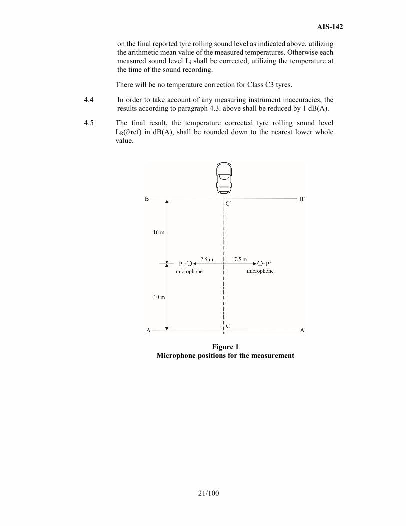
1.1.3 Positioning of the microphone
The microphone (or microphones) shall be located at a distance of 7.5 ± 0.05 m from track reference line CC' (Figure 1) and 1.2 ± 0.02 m above the ground. Its axis of maximum sensitivity shall be horizontal and perpendicular to the path of the vehicle (line CC').
AIS-142
16/100
1.2 Speed measurements
The vehicle speed shall be measured with instruments with accuracy of ±1 km/h or better when the front end of the vehicle has reached line PP’ (Figure 1).
1.3 Temperature measurements
Measurements of air as well as test surface temperature are mandatory. The temperature measuring devices shall be accurate within ± 1 °C.
1.3.1 Air temperature
The temperature sensor is to be positioned in an unobstructed location close to the microphone in such a way that it is exposed to the airflow and protected from direct solar radiation. The latter may be achieved by any shading screen or similar device. The sensor should be positioned at a height of 1.2 ± 0.1 m above the test surface level, to minimize the influence of the test surface thermal radiation at low airflows.
1.3.2 Test surface temperature
The temperature sensor is to be positioned in a location where the temperature measured is representative of the temperature in the wheel tracks, without interfering with the sound measurement.
If an instrument with a contact temperature sensor is used, heat-conductive paste shall be applied between the surface and the sensor to ensure adequate thermal contact.
If a radiation thermometer (pyrometer) is used, the height should be chosen to ensure that a measuring spot with a diameter of ≥ 0.1 m is covered.
1.4 Wind measurement
The device shall be capable of measuring the wind speed with a tolerance of ± 1 m/s. The wind shall be measured at microphone height. The wind direction with reference to the driving direction shall be recorded.
2.0 Conditions of measurement
2.1 Test site
The test site shall consist of a central section surrounded by a substantially flat test area. The measuring section shall be level; the test surface shall be dry and clean for all measurements. The test surface shall not be artificially cooled during or prior the testing.
The test track shall be such that the conditions of a free sound field between the sound source and the microphone are attained to within 1 dB (A). These conditions shall be deemed to be met if there is no large sound reflecting objects, such as fences, rocks, bridges or building within 50 m of the centre of the measuring section. The surface of the test track and the dimensions of the test site shall be in accordance with ISO 10844:2014.

AIS-142
17/100
A central part of at least 10 m radius shall be free of powdery snow, tall grass, loose soil, cinders or the like. There shall be no obstacle, which could affect the sound field within the vicinity of the microphone and no persons shall stand between the microphone and the sound source. The operator carrying out the measurements and any observers attending the measurements shall position themselves so as not to affect the readings of the measuring instruments.
2.2 Meteorological conditions
Measurements shall not be made under poor atmospheric conditions. It shall be ensured that the results are not affected by gusts of wind. Testing shall not be performed if the wind speed at the microphone height exceeds 5 m/s.
Measurements shall not be made if the air temperature is below 5 °C or above 40 °C or the test surface temperature is below 5 °C or above 50 °C.
2.3 Ambient noise
2.3.1 The background sound level (including any wind noise) shall be at least 10 dB (A) less than the measured tyre rolling sound emission. A suitable windscreen may be fitted to the microphone provided that account is taken of its effect on the sensitivity and directional characteristics of the microphone.
2.3.2 Any measurement affected by a sound peak which appears to be unrelated to the characteristics of the general sound level of tyres, shall be ignored.
2.4 Test vehicle requirements
2.4.1 General
The test vehicle shall be a motor vehicle and be fitted with four single tyres on just two axles.
2.4.2 Vehicle load
The vehicle shall be loaded such as to comply with the test tyre loads as specified in paragraph 2.5.2. below.
2.4.3 Wheelbase
The wheelbase between the two axles fitted with the test tyres shall for Class C1 be less than 3.50 m and for Class C2 and Class C3 tyres be less than 5 m.
2.4.4 Measures to minimize vehicle influence on sound level measurements
To ensure that tyre rolling sound is not significantly affected by the test vehicle design the following requirements and recommendations are given.
2.4.4.1 Requirements: (a) Spray suppression flaps or other extra device to suppress spray
shall not be fitted;
(b) Addition or retention of elements in the immediate vicinity of the rims and tyres, which may screen the emitted sound, is not permitted;
AIS-142
18/100
(b) Wheel alignment (toe in, camber and caster) shall be in full accordance with the vehicle manufacturer's recommendations;
(c) Additional sound absorbing material may not be mounted in the wheel housings or under the underbody;
(e) Suspension shall be in such a condition that it does not result in an abnormal reduction in ground clearance when the vehicle is loaded in accordance with the testing requirement. If available, body level Standard systems shall be adjusted to give a ground clearance during testing which is normal for unladen condition.
2.4.4.2 Recommendations to avoid parasitic noise:
(a) Removal or modification on the vehicle that may contribute to the background noise of the vehicle is recommended. Any removals or modifications shall be recorded in the test report;
(b) During testing it should be ascertained that brakes are not poorly released, causing brake noise;
(d) It should be ascertained that electric cooling fans are not operating;
(d) Windows and sliding roof of the vehicle shall be closed during testing.
2.5 Tyres
2.5.1 General
Four identical tyres shall be fitted on the test vehicle. In the case of tyres with a load capacity index in excess of 121 and without any dual fitting indication, two of these tyres of the same type and range shall be fitted to the rear axle of the test vehicle; the front axle shall be fitted with tyres of size suitable for the axle load and planed down to the minimum depth in order to minimize the influence of tyre/road contact noise while maintaining a sufficient level of safety. Winter tyres that may be equipped with studs intended to enhance friction shall be tested without this equipment. Tyres with special fitting requirements shall be tested in accordance with these requirements (e.g. rotation direction). The tyres shall have full tread depth before being run-in.
Tyres are to be tested on rims permitted by the tyre manufacturer.
2.5.2 Tyre loads
The test load Qt for each tyre on the test vehicle shall be 50 to 90 per cent of the reference load Qr, but the average test load Qt,avr of all tyres shall be 75 ± 5 per cent of the reference load Qr.
For all tyres the reference load Qr corresponds to the maximum mass associated with the load capacity index of the tyre. In the case where the load capacity index is constituted by two numbers divided by slash (/), reference shall be made to the first number.
2.5.3 Tyre inflation pressure
Each tyre fitted on the test vehicle shall have a test pressure Pt not higher than the reference pressure Pr and within the interval:
AIS-142
19/100
For Class C2 and Class C3 the reference pressure Pr is the pressure corresponding to the pressure in kPa or to the pressure index marked on the sidewall.
For Class C1 the reference pressure is Pr = 250 kPa for "standard" tyres and 290 kPa for "reinforced" or "extra load" tyres; the minimum test pressure shall be Pt = 150 kPa.
2.5.4 Preparations prior to testing
The tyres shall be "run-in" prior to testing to remove compound nodules or other tyre pattern characteristics resulting from the moulding process. This will normally require the equivalent of about 100 km of normal use on the road.
The tyres fitted to the test vehicle shall rotate in the same direction as when they were run-in.
Prior to testing tyres shall be warmed up by running under test conditions.
3.0 Method of testing
3.1 General conditions
For all measurements the vehicle shall be driven in a straight line over the measuring section (AA' to BB') in such a way that the median longitudinal plane of the vehicle is as close as possible to the line CC'.
When the front end of the test vehicle has reached the line AA' the vehicle driver shall have put the gear selector on neutral position and switched off the engine. If abnormal noise (e.g. ventilator, self-ignition) is emitted by the test vehicle during the measurement, the test shall be disregarded.
3.2 Nature and number of measurements
The maximum sound level expressed in A-weighted decibels (dB(A)) shall be measured to the first decimal place as the vehicle is coasting between lines AA' and BB' (Figure 1 - front end of the vehicle on line AA', rear end of the vehicle on line BB'). This value will constitute the result of the measurement.
At least four measurements shall be made on each side of the test vehicle at test speeds lower than the reference speed specified in paragraph 4.1. below and at least four measurements at test speeds higher than the reference speed. The speeds shall be approximately equally spaced over the speed range specified in paragraph 3.3. below.
3.3 Test speed range
The test vehicle speeds shall be within the range:
(a) From 70 to 90 km/h for Class C1 and Class C2 tyres;
(b) From 60 to 80 km/h for Class C3 tyres.
25 . 1 25 .1
1 .1
r
tr t
r
t r Q
QP P
Q
Q P
AIS-142
20/100
4.0 Interpretation of results
The measurement shall be invalid if an abnormal discrepancy between the values is recorded (see paragraph 2.3.2. of this annex).
4.1 Determination of test result
Reference speed Vref used to determine the final result will be:
(a) 80 km/h for Class C1 and Class C2 tyres;
(b) 70 km/h for Class C3 tyres.
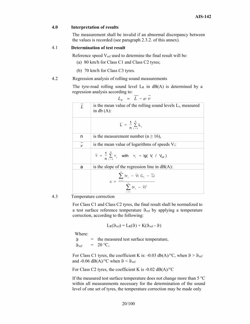
4.2 Regression analysis of rolling sound measurements
The tyre-road rolling sound level LR in dB(A) is determined by a regression analysis according to:
is the mean value of the rolling sound levels Li, measured in db (A):
n is the measurement number (n ≥ 16),
is the mean value of logarithms of speeds Vi:
a is the slope of the regression line in dB(A):
4.3 Temperature correction
For Class C1 and Class C2 tyres, the final result shall be normalized to a test surface reference temperature ref by applying a temperature correction, according to the following:
LR(ref) = LR() + K(ref - )
Where: = the measured test surface temperature, ref = 20 °C,
For Class C1 tyres, the coefficient K is: -0.03 db(A)/°C, when > ref and -0.06 dB(A)/°C when < ref.
For Class C2 tyres, the coefficient K is -0.02 dB(A)/°C
If the measured test surface temperature does not change more than 5 °C within all measurements necessary for the determination of the sound level of one set of tyres, the temperature correction may be made only
aLLR
L
L
n L
i i
n
1
1
1
1 n with V V
i i
n i ref
i lg( / )
a
L Li ii
n
ii
n
( )( )
( )
1
2
1
AIS-142
21/100
on the final reported tyre rolling sound level as indicated above, utilizing the arithmetic mean value of the measured temperatures. Otherwise each measured sound level Li shall be corrected, utilizing the temperature at the time of the sound recording.
There will be no temperature correction for Class C3 tyres.
4.4 In order to take account of any measuring instrument inaccuracies, the results according to paragraph 4.3. above shall be reduced by 1 dB(A).
4.5 The final result, the temperature corrected tyre rolling sound level LR(ref) in dB(A), shall be rounded down to the nearest lower whole value.
Figure 1 Microphone positions for the measurement
AIS-142
22/100
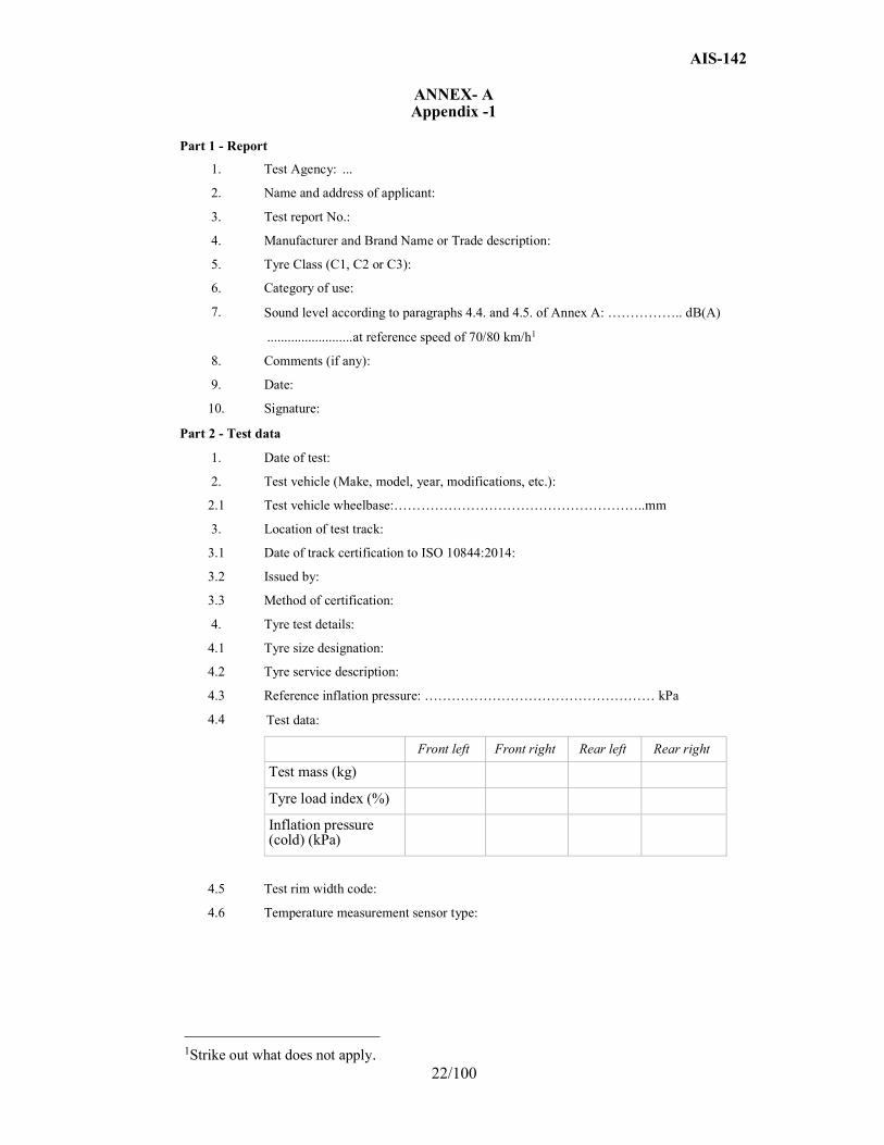
ANNEX- A Appendix -1
Part 1 - Report
1. Test Agency: ...
2. Name and address of applicant:
3. Test report No.:
4. Manufacturer and Brand Name or Trade description:
5. Tyre Class (C1, C2 or C3):
6. Category of use:
7. Sound level according to paragraphs 4.4. and 4.5. of Annex A: …………….. dB(A)
......................... at reference speed of 70/80 km/h1
8. Comments (if any):
9. Date:
10. Signature:
Part 2 - Test data
1. Date of test:
2. Test vehicle (Make, model, year, modifications, etc.):
2.1 Test vehicle wheelbase:………………………………………………..mm
3. Location of test track:
3.1 Date of track certification to ISO 10844:2014:
3.2 Issued by:
3.3 Method of certification:
4. Tyre test details:
4.1 Tyre size designation:
4.2 Tyre service description:
4.3 Reference inflation pressure: …………………………………………… kPa
4.4 Test data:
Front left Front right Rear left Rear right
Test mass (kg)
Tyre load index (%)
Inflation pressure (cold) (kPa)
4.5 Test rim width code:
4.6 Temperature measurement sensor type:
1Strike out what does not apply.
AIS-142
23/100
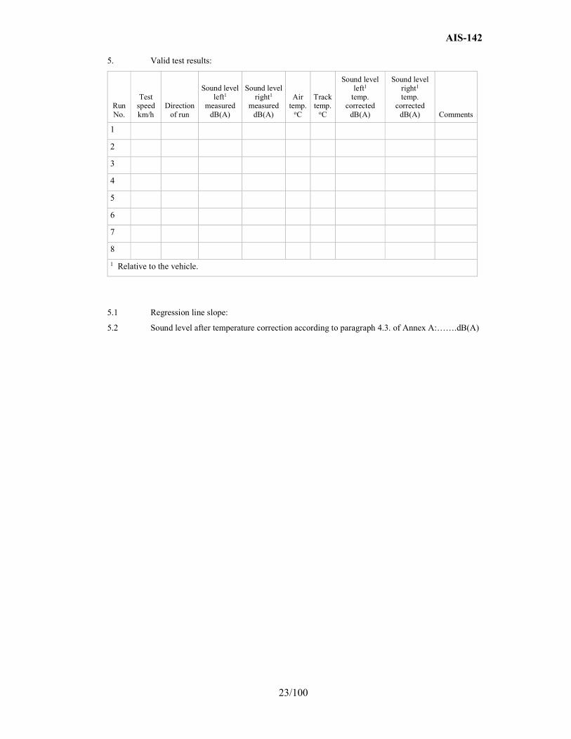
5. Valid test results:
Run No.
Test speed km/h
Direction of run
Sound level left1
measured dB(A)
Sound level right1
measured dB(A)
Air temp.
oC
Track temp.
oC
Sound level left1
temp. corrected
dB(A)
Sound level right1
temp. corrected
dB(A) Comments
1
2
3
4
5
6
7
8
1 Relative to the vehicle.
5.1 Regression line slope:
5.2 Sound level after temperature correction according to paragraph 4.3. of Annex A:…….dB(A)

AIS-142
24/100
ANNEX - B (See 2.1 of Annex - A)
SPECIFICATIONS FOR THE TEST SITE
1.0 Introduction
This annex describes the specifications relating to the physical characteristics and the laying of the test track. These specifications based on a special standard describe the required physical characteristics as well as the test methods for these characteristics.
2.0 Required characteristics of the surface
A surface is considered to conform to this standard provided that the texture and voids content or sound absorption coefficient have been measured and found to fulfil all the requirements of paragraphs 2.1. to 2.4. below and provided that the design requirements (paragraph 3.2. below) have been met.
2.1 Residual voids content
The residual voids content (VC) of the test track paving mixture shall not exceed 8 per cent. For the measurement procedure, see paragraph 4.1. of this annex.
2.2 Sound absorption coefficient
If the surface fails to comply with the residual voids content requirement, the surface is acceptable only if its sound absorption coefficient α ≤ 0.10. For the measurement procedure, see paragraph 4.2. below The requirements of paragraph 2.1. above are met also if only sound absorption has been measured and found to be α ≤ 0.10.
Note: The most relevant characteristic is the sound absorption, although the residual voids content is more familiar among road constructors. However, sound absorption needs to be measured only if the surface fails to comply with the voids requirement. This is motivated because the latter is connected with relatively large uncertainties in terms of both measurements and relevance and some surfaces therefore erroneously may be rejected when based only on the voids measurement.
2.3 Texture depth
The texture depth (TD) measured according to the volumetric method (see paragraph 4.3. below) shall be: TD ≥ 0.4 mm
2.4 Homogeneity of the surface
Every practical effort shall be taken to ensure that the surface is made to be as homogeneous as possible within the test area. This includes the texture and voids content, but it should also be observed that if the rolling process results in more effective rolling at some places than others, the texture may be different and unevenness causing bumps may also occur.
2.5 Period of testing
In order to check whether the surface continues to conform to the texture and voids content or sound absorption requirements stipulated in this standard, periodic testing of the surface shall be done at the following intervals:
AIS-142
25/100
(a) For residual voids content (VC) or sound absorption (α):
When the surface is new:
If the surface meets the requirements when new, no further periodical testing is required. If it does not meet the requirement when it is new, it may do so later because surfaces tend to become clogged and compacted with time;
(b) For texture depth (TD):
When the surface is new:
When the noise testing starts (Note: Not before four weeks after laying); Then every twelve months.
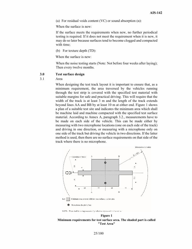
3.0 Test surface design 3.1 Area
When designing the test track layout it is important to ensure that, as a minimum requirement, the area traversed by the vehicles running through the test strip is covered with the specified test material with suitable margins for safe and practical driving. This will require that the width of the track is at least 3 m and the length of the track extends beyond lines AA and BB by at least 10 m at either end. Figure 1 shows a plan of a suitable test site and indicates the minimum area which shall be machine laid and machine compacted with the specified test surface material. According to Annex A, paragraph 3.2., measurements have to be made on each side of the vehicle. This can be made either by measuring with two microphone locations (one on each side of the track) and driving in one direction, or measuring with a microphone only on one side of the track but driving the vehicle in two directions. If the latter method is used, then there are no surface requirements on that side of the track where there is no microphone.
Figure 1 Minimum requirements for test surface area. The shaded part is called
"Test Area"
AIS-142
26/100
3.2 Design and preparation of the surface
3.2.1 Basic design requirements
The test surface shall meet four design requirements:
3.2.1.1 It shall be a dense asphaltic concrete.
3.2.1.2 The maximum chipping size shall be 8 mm (tolerances allow from 6.3 mm to 10 mm).
3.2.1.3 The thickness of the wearing course shall be ≥ 30 mm.
3.2.1.4 The binder shall be a straight penetration grade bitumen without modification.
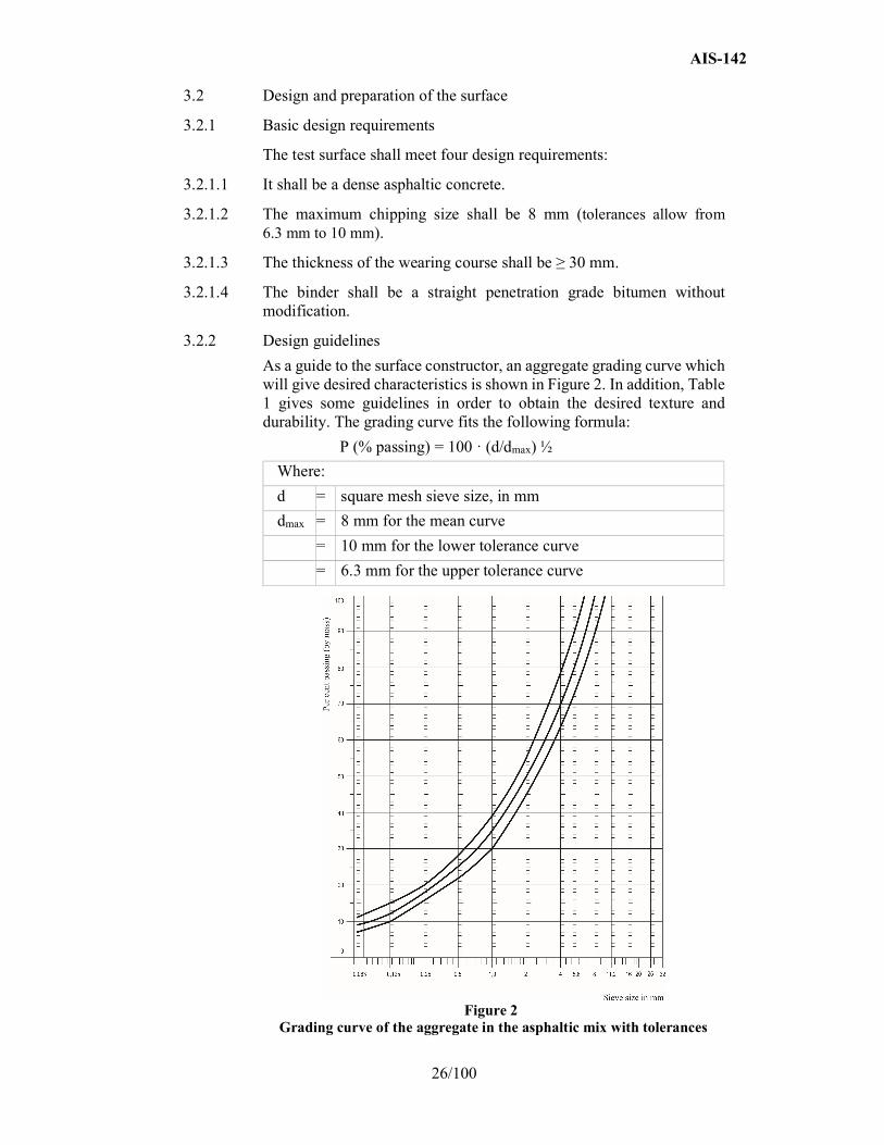
3.2.2 Design guidelines
As a guide to the surface constructor, an aggregate grading curve which will give desired characteristics is shown in Figure 2. In addition, Table 1 gives some guidelines in order to obtain the desired texture and durability. The grading curve fits the following formula:
P (% passing) = 100 · (d/dmax) ½
Where:
d = square mesh sieve size, in mm
dmax = 8 mm for the mean curve
= 10 mm for the lower tolerance curve
= 6.3 mm for the upper tolerance curve
Figure 2
Grading curve of the aggregate in the asphaltic mix with tolerances

AIS-142
27/100
In addition to the above, the following recommendations are given:
(a) The sand fraction (0.063 mm < square mesh sieve size < 2 mm) shall include no more than 55 per cent natural sand and at least 45 per cent crushed sand;
(b) The base and sub-base shall ensure a good stability and evenness, according to best road construction practice;
(c) The chippings shall be crushed (100 per cent crushed faces) and of a material with a high resistance to crushing;
(d) The chippings used in the mix shall be washed;
(e) No extra chippings shall be added onto the surface;
(f) The binder hardness expressed as PEN value shall be 40-60, 60-80 or even 80-100 depending on the climatic conditions of the country. The rule is that as hard a binder as possible shall be used, provided this is consistent with common practice;
(g) The temperature of the mix before rolling shall be chosen so as to achieve by subsequent rolling the required voids content. In order to increase the probability of satisfying the specifications of paragraphs 2.1. to 2.4. above, the compactness shall be studied not only by an appropriate choice of mixing temperature, but also by an appropriate number of passings and by the choice of compacting vehicle.
Table 1
Design guidelines
Target values
Tolerances
By total mass of mix
By mass of the aggregate
Mass of stones, square mesh sieve (SM) > 2 mm
47.6 % 50.5 % ±5 %
Mass of sand 0.063 < SM < 2 mm
38.0 % 40.2 % ±5 %
Mass of filler SM < 0.063 mm 8.8 % 9.3 % ±5 %
Mass of binder (bitumen) 5.8 % N.A. ±0.5 %
Max. chipping size 8 mm 6.3 - 10 mm
Binder hardness (see paragraph 3.2.2. (f))
Polished stone value (PSV) > 50
Compactness, relative to Marshall Compactness
98 %
AIS-142
28/100
4.0 Test method
4.1 Measurement of the residual voids content
For the purpose of this measurement, cores have to be taken from the track in at least four different positions, which are equally distributed in the test area between lines AA and BB (see Figure 1). In order to avoid in homogeneity and unevenness in the wheel tracks, cores should not be taken in wheel tracks themselves, but close to them. Two cores (minimum) should be taken close to the wheel tracks and one core (minimum) should be taken approximately midway between the wheel tracks and each microphone location.
If there is a suspicion that the condition of homogeneity is not met (see paragraph 2.4. above), cores shall be taken from more locations within the test area.
The residual voids content has to be determined for each core, then the average value from all cores shall be calculated and compared with the requirement of paragraph 2.1. of this annex. In addition, no single core shall have a voids value, which is higher than 10 per cent.
The test surface constructor is reminded of the problem, which may arise when the test area is heated by pipes or electrical wires and cores shall be taken from this area. Such installations shall be carefully planned with respect to future core drilling locations. It is recommended to leave a few locations of size approximately 200 mm x 300 mm where there are no wires/pipes or where the latter are located deep enough in order not to be damaged by cores taken from the surface layer.
4.2 Sound absorption coefficient
The sound absorption coefficient (normal incidence) shall be measured by the impedance tube method using the procedure specified in ISO 10534-1:1996 or ISO 10534-2:1998.
Regarding test specimens, the same requirements shall be followed as regarding the residual voids content (see paragraph 4.1. above). The sound absorption shall be measured in the range between 400 Hz and 800 Hz and in the range between 800 Hz and 1,600 Hz (at least at the centre frequencies of third octave bands) and the maximum values shall be identified for both of these frequency ranges. Then these values, for all test cores, shall be averaged to constitute the final result.
4.3 Volumetric macro-texture measurement For the purpose of this standard, texture depth measurements shall be made on at least 10 positions evenly spaced along the wheel tracks of the test strip and the average value taken to compare with the specified minimum texture depth. See Standard ISO 10844:2014 for description of the procedure.

AIS-142
29/100
5.0 Stability in time and maintenance
5.1 Age influence
In common with any other surfaces, it is expected that the tyre rolling sound level measured on the test surface may increase slightly during the first 6-12 months after construction.
The surface will achieve its required characteristics not earlier than four weeks after construction. The influence of age on the noise from trucks is generally less than that from cars.
The stability over time is determined mainly by the polishing and compaction by vehicles driving on the surface. It shall be periodically checked as stated in paragraph 2.5. above.
5.2 Maintenance of the surface
Loose debris or dust, which could significantly reduce the effective texture depth shall be removed from the surface. In countries with winter climates, salt is sometimes used for de-icing. Salt may alter the surface temporarily or even permanently in such a way as to increase noise and is therefore not recommended.
5.3 Repaving the test area
If it is necessary to repave the test track, it is usually unnecessary to repave more than the test strip (of 3 m width in Figure 1) where vehicles are driving, provided the test area outside the strip met the requirement of residual voids content or sound absorption when it was measured.
6.0 Documentation of the test surface and of tests performed on it
6.1 Documentation of the test surface The following data shall be given in a document describing the test surface:
6.1.1 The location of the test track;
6.1.2 Type of binder, binder hardness, type of aggregate, maximum theoretical density of the concrete (DR), thickness of the wearing course and grading curve determined from cores from the test track;
6.1.3 Method of compaction (e.g. type of roller, roller mass, number of passes);
6.1.4 Temperature of the mix, temperature of the ambient air and wind speed during laying of the surface;
6.1.5 Date when the surface was laid and contractor;
6.1.6 All or at least the latest test result, including:
6.1.6.1 The residual voids content of each core;
6.1.6.2 The locations in the test area from where the cores for voids measurements have been taken;

AIS-142
30/100
6.1.6.3 The sound absorption coefficient of each core (if measured). Specify the results both for each core and each frequency range as well as the overall average;
6.1.6.4 The locations in the test area from where the cores for absorption measurement have been taken;
6.1.6.5 Texture depth, including the number of tests and standard deviation;
6.1.6.6 The institution responsible for tests according to paragraphs 6.1.6.1. and 6.1.6.2. above and the type of equipment used;
6.1.6.7 Date of the test(s) and date when the cores were taken from the test track.
6.2 Documentation of vehicle noise tests conducted on the surface
In the document describing the vehicle noise test(s) it shall be stated whether all the requirements of this standard were fulfilled or not. Reference shall be given to a document according to paragraph 6.1. above describing the results which verify this.
AIS-142
31/100
ANNEX - C (See 3.5)
TESTING PROCEDURE FOR MEASURING WET GRIP
(A) - C1 category tyres
1.0 Reference standards
The following documents listed apply.
1.1 ASTM E 303-93 (Reapproved 2008), Standard Test Method for Measuring Surface Frictional Properties Using the British Pendulum Tester.
1.2. ASTM E 501-08, Standard Specification for Standard Rib Tire for Pavement Skid-Resistance Tests.
1.3 ASTM E 965-96 (Reapproved 2006), Standard Test Method for Measuring Pavement Macrotexture Depth Using a Volumetric Technique.
1.4. ASTM E 1136-93 (Reapproved 2003), Standard Specification for a Radial Standard Reference Test Tire P195/75R14.
1.5. ASTM F 2493-08, Standard Specification for a Radial Standard Reference Test Tire P225/60R16.
2.0 Definitions
For the purposes of testing wet grip of C1 tyres:
2.1. "Test run" means a single pass of a loaded tyre over a given test track surface.
2.2. "Test tyre(s)" means a candidate tyre, a reference tyre or a control tyre or tyre set that is used in a test run.
2.3. "Candidate tyre(s) (T)" means a tyre or a tyre set that is tested for the purpose of calculating its wet grip index.
2.4. "Reference tyre(s) (R)" means a tyre or a tyre set that has the characteristics indicated in the ASTM F 2493-08 and referred to as the Standard Reference Test Tyre.
2.5. "Control tyre(s) (C)" means an intermediate tyre or a set of intermediate tyres which is used when the candidate tyre and the reference tyre cannot be directly compared on the same vehicle.
2.6. "Braking force of a tyre" means the longitudinal force, expressed in newton, resulting from braking torque application.
2.7. "Braking force coefficient of a tyre (BFC)" means the ratio of the braking force to the vertical load.
2.8 "Peak braking force coefficient of a tyre" means the maximum value of a tyre braking force coefficient that occurs prior to wheel lockup as the braking torque is progressively increased.
AIS-142
32/100
2.9. "Lockup of a wheel" means the condition of a wheel in which its rotational velocity about the wheel spin axis is zero and it is prevented from rotating in the presence of applied wheel torque.
2.10. "Vertical load" means the load in newton imposed on the tyre perpendicular to the road surface.
2.11. "Tyre test vehicle" means a dedicated special purpose vehicle which has instruments to measure the vertical and the longitudinal forces on one test tyre during braking.
2.12. "SRTT14" means the ASTM E 1136-93 (Reapproved 2003), Standard Specification for a Radial Standard Reference Test Tire P195/75R14.
2.13. "SRTT16" means the ASTM F 2493-08, Standard Specification for a Radial Standard Reference Test Tire P225/60R16.
3.0 General test conditions
3.1. Track characteristics The test track shall have the following characteristics:
3.1.1.
The surface shall have a dense asphalt surface with a uniform gradient of not more than 2 per cent and shall not deviate more than 6 mm when tested with a 3 m straight edge.
3.1.2. The surface shall have a pavement of uniform age, composition, and wear. The test surface shall be free of loose material and foreign deposits.
3.1.3. The maximum chipping size shall be 10 mm (tolerances permitted from 8 mm to 13 mm).
3.1.4. The texture depth as measured by a sand patch shall be 0.7 ± 0.3 mm. It shall be measured in accordance with ASTM E 965-96 (Reapproved 2006).
3.1.5. The wetted frictional properties of the surface shall be measured with either method (a) or (b) in paragraph 3.2.
3.2. Methods to measure the wetted frictional properties of the surface
3.2.1 British Pendulum Number (BPN) method (a)
The British Pendulum Number method shall be as defined in ASTM E 303-93 (Reapproved in 2008).
Pad rubber component formulation and physical properties shall be as specified in ASTM E 501-08.
The averaged British Pendulum Number (BPN) shall be between 42 and 60 BPN after temperature correction as follows.
BPN shall be corrected by the wetted road surface temperature. Unless temperature correction recommendations are indicated by the British pendulum manufacturer, the following formula is used:
BPN = BPN(measured value) + temperature correction

AIS-142
33/100
Temperature correction = -0.0018 t2 + 0.34 t - 6.1
Where t is the wetted road surface temperature in degrees Celsius.
Effects of slider pad wear: the pad shall be removed for maximum wear when the wear on the striking edge of the slider reaches 3.2 mm in the plane of the slider or 1.6 mm vertical to it in accordance with paragraph 5.2.2. and Figure 3 of ASTM E 303-93 (Reapproved 2008).
For the purpose of checking track surface BPN consistency for the measurement of wet grip on an instrumented passenger car: the BPN values of the test track should not vary over the entire stopping distance so as to decrease the dispersion of test results. The wetted frictional properties of the surface shall be measured five times at each point of the BPN measurement every 10 meters and the coefficient of variation of the averaged BPN shall not exceed 10 per cent.
3.2.2. ASTM E 1136 Standard Reference Test Tyre method (b)
By derogation with paragraph 2.4. above, this method uses the reference tyre that has the characteristics indicated in the ASTM E 1136-93 (Reapproved 2003) and referred to as SRTT14.
The average peak braking force coefficient (µpeak,ave) of the SRTT14 shall be 0.7 ± 0.1 at 65 km/h.
The average peak braking force coefficient (µpeak,ave) of the SRTT14 shall be corrected for the wetted road surface temperature as follows:
Peak braking force coefficient (µpeak,ave) = peak braking force coefficient (measured) + temperature correction
Temperature correction = 0.0035 x (t - 20)
Where t is the wetted road surface temperature in degrees Celsius.
3.3.
Atmospheric conditions
The wind conditions shall not interfere with wetting of the surface (wind-shields are allowed).
Both the wetted surface temperature and the ambient temperature shall be between 2 °C and 20 °C for snow tyres and 5 °C and 35 °C for normal tyres.
The wetted surface temperature shall not vary during the test by more than 10 °C.
The ambient temperature must remain close to the wetted surface temperature; the difference between the ambient and the wetted surface temperatures must be less than 10 °C.
4.0 Testing methods for measuring wet grip
For the calculation of the wet grip index (G) of a candidate tyre, the wet grip braking performance of the candidate tyre is compared to the wet grip braking performance of the reference tyre on a vehicle travelling straight ahead on a wet, paved surface. It is measured with one of the following methods:

AIS-142
34/100
(a) Vehicle method consisting of testing a set of tyres mounted on an instrumented passenger car;
(b) Testing method using a trailer towed by a vehicle or a tyre test vehicle, equipped with the test tyre(s).
4.1. Testing method (a) using an instrumented passenger car
4.1.1.
Principle
The testing method covers a procedure for measuring the deceleration performance of C1 tyres during braking, using an instrumented passenger car equipped with an Antilock Braking System (ABS), where "instrumented passenger car" means a passenger car that is fitted with the measuring equipment listed in paragraph 4.1.2.2. below for the purpose of this testing method. Starting with a defined initial speed, the brakes are applied hard enough on four wheels at the same time to activate the ABS. The average deceleration is calculated between two pre-defined speeds.
4.1.2. Equipment
4.1.2.1. Vehicle
Permitted modifications on the passenger car are as follows:
(a) Those allowing the number of tyre sizes that can be mounted on the vehicle to be increased;
(b) Those permitting automatic activation of the braking device to be installed;
(c) Any other modification of the braking system is prohibited.
4.1.2.2. Measuring equipment
The vehicle shall be fitted with a sensor suitable for measuring speed on a wet surface and distance covered between two speeds.
To measure vehicle speed, a fifth wheel or non-contact speed-measuring system shall be used.
4.1.3. Conditioning of the test track and wetting condition
The test track surface shall be watered at least half an hour prior to testing in order to equalize the surface temperature and water temperature. External watering should be supplied continuously throughout testing. For the whole testing area, the water depth shall be 1.0 ± 0.5 mm, measured from the peak of the pavement.
The test track should then be conditioned by conducting at least ten test runs with tyres not involved in the test programme at 90 km/h.
4.1.4. Tyres and rims
4.1.4.1. Tyre preparation and break-in
The test tyres shall be trimmed to remove all protuberances on the tread surface caused by mould air vents or flashes at mould junctions.
AIS-142
35/100
Fit the test tyres on rims specified by a recognized tyre and rim standards organization as listed in Appendix 4 to Annex D to this Standard.
4.1.4.2 Tyre load
The static load on each axle tyre shall lie between 60 per cent and 90 per cent of the tested tyre load capacity. Tyre loads on the same axle should not differ by more than 10 per cent.
4.1.4.3
Tyre inflation pressure
On the front and rear axles, the inflation pressures shall be 220 kPa (for standard- and extra-load tyres). The tyre pressure should be checked just prior to testing at ambient temperature and adjusted if required.
4.1.5. Procedure
4.1.5.1. Test run
The following test procedure applies for each test run.
4.1.5.1.1.
The passenger car is driven in a straight line up to 85 ± 2 km/h.
4.1.5.1.2. Once the passenger car has reached 85 ± 2 km/h, the brakes are always activated at the same place on the test track referred to as "braking starting point", with a longitudinal tolerance of 5 m and a transverse tolerance of 0.5 m.
4.1.5.1.3 The brakes are activated either automatically or manually.
4.1.5.1.3.1. The automatic activation of the brakes is performed by means of a detection system made of two parts, one indexed to the test track and one on board the passenger car.
4.1.5.1.3.2 The manual activation of the brakes depends on the type of transmission as follows. In both cases, a minimum of 600 N pedal efforts is required.
For manual transmission, the driver should release the clutch and depress the brake pedal sharply, holding it down as long as necessary to perform the measurement.
For automatic transmission, the driver should select neutral gear and then depress the brake pedal sharply, holding it down as long as necessary to perform the measurement.
4.1.5.1.4
The average deceleration is calculated between 80 km/h and 20 km/h.
If any of the specifications listed above (including speed tolerance, longitudinal and transverse tolerance for the braking starting point, and braking time) are not met when a test run is made, the measurement is discarded and a new test run is made.
AIS-142
36/100
4.1.5.2. Test cycle
A number of test runs are made in order to measure the wet grip index of a set of candidate tyres (T) according to the following procedure, whereby each test run shall be made in the same direction and up to three different sets of candidate tyres may be measured within the same test cycle:
4.1.5.2.1. First, the set of reference tyres are mounted on the instrumented passenger car.
4.1.5.2.2. After at least three valid measurements have been made in accordance with paragraph 4.1.5.1. above, the set of reference tyres is replaced by a set of candidate tyres.
4.1.5.2.3
After six valid measurements of the candidate tyres are performed, two more sets of candidate tyres may be measured.
4.1.5.2.4. The test cycle is closed by three more valid measurements of the same set of reference tyres as at the beginning of the test cycle.
Examples:
(a) The run order for a test cycle of three sets of candidate tyres (T1 to T3) plus a set of reference tyres (R) would be the following:
R-T1-T2-T3-R
(b) The run order for a test cycle of five sets of candidate tyres (T1 to T5) plus a set of reference tyres (R) would be the following:
R-T1-T2-T3-R-T4-T5-R
4.1.6. Processing of measurement results
4.1.6.1.
Calculation of the average deceleration (AD)
The average deceleration (AD) is calculated for each valid test run in m/s2 as follows:
Where:
Sf is the final speed in m/s; Sf = 20 km/h = 5.556 m/s
Si is the initial speed in m/s; Si = 80 km/h = 22.222 m/s
d is the distance covered between Si and Sf in metre.
4.1.6.2. Validation of results
The AD coefficient of variation is calculated as follows:
(Standard deviation / Average) x 100.
For the reference tyres (R): If the AD coefficient of variation of any two consecutive groups of three tests runs of the reference tyre set is
d
S S AD
if
2
2 2
AIS-142
37/100
higher than 3 per cent, all data should be discarded and the test repeated for all test tyres (the candidate tyres and the reference tyres).
For the candidate tyres (T): The AD coefficients of variation are calculated for each candidate tyre set. If one coefficient of variation is higher than 3 per cent, the data should be discarded and the test repeated for that candidate tyre set.
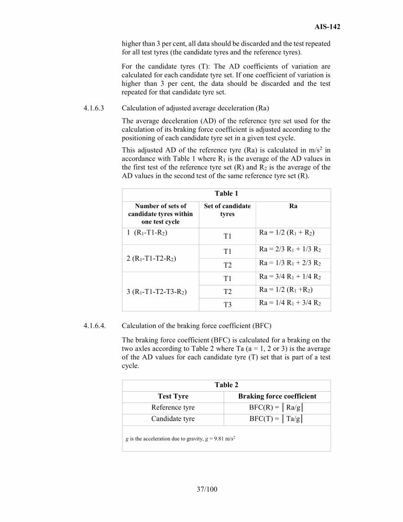
4.1.6.3 Calculation of adjusted average deceleration (Ra)
The average deceleration (AD) of the reference tyre set used for the calculation of its braking force coefficient is adjusted according to the positioning of each candidate tyre set in a given test cycle.
This adjusted AD of the reference tyre (Ra) is calculated in m/s2 in accordance with Table 1 where R1 is the average of the AD values in the first test of the reference tyre set (R) and R2 is the average of the AD values in the second test of the same reference tyre set (R).
Table 1
Number of sets of candidate tyres within
one test cycle
Set of candidate tyres
Ra
1 (R1-T1-R2) T1 Ra = 1/2 (R1 + R2)
2 (R1-T1-T2-R2) T1 Ra = 2/3 R1 + 1/3 R2
T2 Ra = 1/3 R1 + 2/3 R2
3 (R1-T1-T2-T3-R2)
T1 Ra = 3/4 R1 + 1/4 R2
T2 Ra = 1/2 (R1 +R2)
T3 Ra = 1/4 R1 + 3/4 R2
4.1.6.4. Calculation of the braking force coefficient (BFC)
The braking force coefficient (BFC) is calculated for a braking on the two axles according to Table 2 where Ta (a = 1, 2 or 3) is the average of the AD values for each candidate tyre (T) set that is part of a test cycle.
Table 2
Test Tyre Braking force coefficient
Reference tyre BFC(R) = │Ra/g│
Candidate tyre BFC(T) = │Ta/g│
g is the acceleration due to gravity, g = 9.81 m/s2
AIS-142
38/100
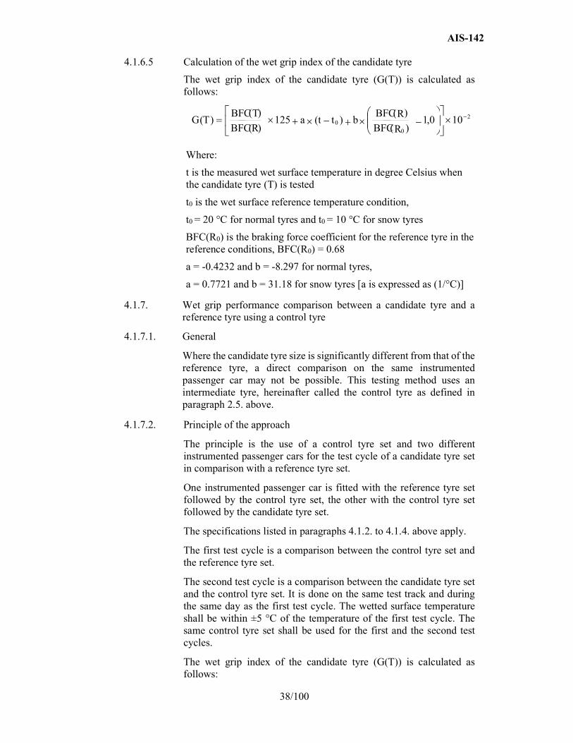
4.1.6.5 Calculation of the wet grip index of the candidate tyre
The wet grip index of the candidate tyre (G(T)) is calculated as follows:
Where:
t is the measured wet surface temperature in degree Celsius when the candidate tyre (T) is tested
t0 is the wet surface reference temperature condition,
t0 = 20 °C for normal tyres and t0 = 10 °C for snow tyres
BFC(R0) is the braking force coefficient for the reference tyre in the reference conditions, BFC(R0) = 0.68
a = -0.4232 and b = -8.297 for normal tyres,
a = 0.7721 and b = 31.18 for snow tyres [a is expressed as (1/°C)]
4.1.7.
Wet grip performance comparison between a candidate tyre and a reference tyre using a control tyre
4.1.7.1. General
Where the candidate tyre size is significantly different from that of the reference tyre, a direct comparison on the same instrumented passenger car may not be possible. This testing method uses an intermediate tyre, hereinafter called the control tyre as defined in paragraph 2.5. above.
4.1.7.2. Principle of the approach
The principle is the use of a control tyre set and two different instrumented passenger cars for the test cycle of a candidate tyre set in comparison with a reference tyre set.
One instrumented passenger car is fitted with the reference tyre set followed by the control tyre set, the other with the control tyre set followed by the candidate tyre set.
The specifications listed in paragraphs 4.1.2. to 4.1.4. above apply.
The first test cycle is a comparison between the control tyre set and the reference tyre set.
The second test cycle is a comparison between the candidate tyre set and the control tyre set. It is done on the same test track and during the same day as the first test cycle. The wetted surface temperature shall be within ±5 °C of the temperature of the first test cycle. The same control tyre set shall be used for the first and the second test cycles.
The wet grip index of the candidate tyre (G(T)) is calculated as follows:
2
00 10 0 , 1
) (
)() ( 125
) (
) ()(
R BFCRBFC
b t taR BFC
T BFC T G

AIS-142
39/100
G(T) = G1 × G2
Where:
G1 is the relative wet grip index of the control tyre (C) compared to the reference tyre (R) calculated as follows:
G2 is the relative wet grip index of the candidate tyre (T) compared to the control tyre (C) calculated as follows:
4.1.7.3. Storage and preservation
It is necessary that all the tyres of a control tyre set have been stored in the same conditions. As soon as the control tyre set has been tested in comparison with the reference tyre, the specific storage conditions defined in ASTM E 1136-93 (Reapproved 2003) shall be applied.
4.1.7.4 Replacement of reference tyres and control tyres
When irregular wear or damage results from tests, or when wear influences the test results, the use of the tyre shall be discontinued.
4.2
Testing method (b) using a trailer towed by a vehicle or a tyre test vehicle
4.2.1. Principle
The measurements are conducted on test tyres mounted on a trailer towed by a vehicle (hereafter referred to as tow vehicle) or on a tyre test vehicle. The brake in the test position is applied firmly until sufficient braking torque is generated to produce the maximum braking force that will occur prior to wheel lockup at a test speed of 65 km/h.
4.2.2. Equipment
4.2.2.1.
Tow vehicle and trailer or tyre test vehicle
The tow vehicle or the tyre test vehicle shall have the capability of maintaining the specified speed of 65 ± 2 km/h even under the maximum braking forces.
The trailer or the tyre test vehicle shall be equipped with one place where the tyre can be fitted for measurement purposes hereafter called 'test position' and the following accessories:
(a) Equipment to activate brakes in the test position;
(b) A water tank to store sufficient water to supply the road surface wetting system, unless external watering is used;
001 10-2
.1
) (
) ( )( 125
) ( ) (
RBFC R BFC
b tt a RBFC
C BFC G 0
) ( 2
C BFC
BFC (T)G
AIS-142
40/100
(c) Recording equipment to record signals from transducers installed at the test position and to monitor water application rate if the self-watering option is used.
The maximum variation of toe-settings and camber angle for the test position shall be within ±0.5° with maximum vertical load. Suspension arms and bushings shall have sufficient rigidity necessary to minimize free play and ensure compliance under application of maximum braking forces. The suspension system shall provide adequate load-carrying capacity and be of such a design as to isolate suspension resonance.
The test position shall be equipped with a typical or special automotive brake system which can apply sufficient braking torque to produce the maximum value of braking test wheel longitudinal force at the conditions specified.
The brake application system shall be able to control the time interval between initial brake application and peak longitudinal force as specified in paragraph 4.2.7.1. below.
The trailer or the tyre test vehicle shall be designed to accommodate the range of candidate tyre sizes to be tested.
The trailer or the tyre test vehicle shall have provisions for adjustment of vertical load as specified in paragraph 4.2.5.2. below
4.2.2.2. Measuring equipment
The test wheel position on the trailer or the tyre test vehicle shall be equipped with a rotational wheel velocity measuring system and with transducers to measure the braking force and vertical load at the test wheel.
General requirements for measurement system: The instrumentation system shall conform to the following overall requirements at ambient temperatures between 0 °C and 45 °C:
(a) Overall system accuracy, force: ± 1.5 per cent of the full scale of the vertical load or braking force;
(b) Overall system accuracy, speed: ± 1.5 per cent of speed or ± 1.0 km/h, whichever is greater.
Vehicle speed: To measure vehicle speed, a fifth wheel or non-contact precision speed-measuring system should be used.
Braking forces: The braking force-measuring transducers shall measure longitudinal force generated at the tyre–road interface as a result of brake application within a range from 0 per cent to at least 125 per cent of the applied vertical load. The transducer design and location shall minimize inertial effects and vibration-induced mechanical resonance.
Vertical load: The vertical load-measuring transducer shall measure the vertical load at the test position during brake application. The transducer shall have the same specifications as described previously.
AIS-142
41/100
Signal conditioning and recording system: All signal conditioning and recording equipment shall provide linear output with necessary gain and data reading resolution to meet the specified previous requirements. In addition, the following requirements apply:
(a) The minimum frequency response shall be flat from 0 Hz to 50 Hz (100 Hz) within ±1 per cent full scale;
(b) The signal-to-noise ratio shall be at least 20/1;
(c) The gain shall be sufficient to permit full-scale display for full-scale input signal level;
(d) The input impedance shall be at least ten times larger than the output impedance of the signal source;
(e) The equipment shall be insensitive to vibrations, acceleration, and changes in ambient temperature.
4.2.3 Conditioning of the test track The test track should be conditioned by conducting at least ten test runs with tyres not involved in the test program at 65 ± 2 km/h.
4.2.4 Wetting conditions The tow vehicle and trailer or the tyre test vehicle may be optionally equipped with a pavement-wetting system, less the storage tank, which, in the case of the trailer, is mounted on the tow vehicle. The water being applied to the pavement ahead of the test tyres shall be supplied by a nozzle suitably designed to ensure that the water layer encountered by the test tyre has a uniform cross section at the test speed with a minimum splash and overspray. The nozzle configuration and position shall ensure that the water jets are directed towards the test tyre and pointed towards the pavement at an angle of 20° to 30°. The water shall strike the pavement 250 mm to 450 mm ahead of the centre of tyre contact. The nozzle shall be located 25 mm above the pavement or at the minimum height required to clear obstacles which the tester is expected to encounter, but in no case more than 100 mm above the pavement. The water layer shall be at least 25 mm wider than the test tyre tread and applied so the tyre is centrally located between the edges. Water delivery rate shall ensure a water depth of 1.0 ± 0.5 mm and shall be consistent throughout the test to within ±10 per cent. The volume of water per unit of wetted width shall be directly proportional to the test speed. The quantity of water applied at 65 km/h shall be 18 l/s per meter of width of wetted surface in case of a water depth of 1.0 mm.
AIS-142
42/100
4.2.5. Tyres and rims
4.2.5.1.
Tyre preparation and break-in
The test tyres shall be trimmed to remove all protuberances on the tread surface caused by mould air vents or flashes at mould junctions.
The test tyre shall be mounted on the test rim declared by the tyre manufacturer.
A proper bead seat should be achieved by the use of a suitable lubricant. Excessive use of lubricant should be avoided to prevent slipping of the tyre on the wheel rim.
The test tyres/rim assemblies shall be stored in a location for a minimum of two hours such that they all have the same ambient temperature prior to testing. They should be shielded from the sun to avoid excessive heating by solar radiation.
For tyre break-in, two braking runs shall be performed under the load, pressure and speed as specified in paragraphs 4.2.5.2, 4.2.5.3 and 4.2.7.1 respectively.
4.2.5.2. Tyre load
The test load on the test tyre is 75 ± 5 per cent of the tyre load capacity.
4.2.5.3. Tyre inflation pressure
The test tyre cold inflation pressure shall be 180 kPa for standard-load tyres. For extra-load tyres, the cold inflation pressure shall be 220 kPa.
The tyre pressure should be checked just prior to testing at ambient temperature and adjusted if required.
4.2.6 Preparation of the tow vehicle and trailer or the tyre test vehicle
4.2.6.1.
Trailer
For one axle trailers, the hitch height and transverse position shall be adjusted once the test tyre has been loaded to the specified test load in order to avoid any disturbance of the measuring results. The longitudinal distance from the centre line of the articulation point of the coupling to the transverse centre line of the axle of the trailer shall be at least ten times the "hitch height" or the "coupling (hitch) height".
4.2.6.2. Instrumentation and equipment
Install the fifth wheel, when used, in accordance with the manufacturer’s specifications and locate it as near as possible to the mid-track position of the tow trailer or the tyre test vehicle.
4.2.7 Procedure
4.2.7.1.
Test run
The following procedure applies for each test run:
4.2.7.1.1. The tow vehicle or the tyre test vehicle is driven onto the test track in a straight line at the specified test speed 65 ± 2 km/h.

AIS-142
43/100
4.2.7.1.2. The recording system is launched.
4.2.7.1.3. Water is delivered to the pavement ahead of the test tyre approximately 0.5 s prior to brake application (for internal watering system).
4.2.7.1.4. The trailer brakes are activated within 2 metres of a measurement point of the wetted frictional properties of the surface and sand depth in accordance with paragraphs 3.1.4. and 3.1.5. above. The rate of braking application shall be such that the time interval between initial application of force and peak longitudinal force is in the range 0.2 s to 0.5 s.
4.2.7.1.5. The recording system is stopped.
4.2.7.2. Test cycle
A number of test runs are made in order to measure the wet grip index of the candidate tyre (T) according to the following procedure, whereby each test run shall be made from the same spot on the test track and in the same direction. Up to three candidate tyres may be measured within the same test cycle, provided that the tests are completed within one day.
4.2.7.2.1 First, the reference tyre is tested.
4.2.7.2.2.
After at least six valid measurements are performed in accordance with paragraph 4.2.7.1. above, the reference tyre is replaced by the candidate tyre.
4.2.7.2.3. After six valid measurements of the candidate tyre are performed, two more candidate tyres may be measured.
4.2.7.2.4. The test cycle is closed by six more valid measurements of the same reference tyre as at the beginning of the test cycle.
Examples:
(a) The run order for a test cycle of three candidate tyres (T1 to T3) plus the reference tyre (R) would be the following:
R-T1-T2-T3-R
(b) The run order for a test cycle of five candidate tyres (T1 to T5) plus the reference tyre R would be the following:
R-T1-T2-T3-R-T4-T5-R
4.2.8. Processing of measurement results
4.2.8.1.
Calculation of the peak braking force coefficient
The tyre peak braking force coefficient (µpeak) is the highest value of µ(t) before lockup occurs calculated as follows for each test run. Analogue signals should be filtered to remove noise. Digitally recorded signals must be filtered using a moving average technique.

AIS-142
44/100
Where:
µ (t) is the dynamic tyre braking force coefficient in real time;
fh (t) is the dynamic braking force in real time, in N;
fv (t) is the dynamic vertical load in real time, in N.
4.2.8.2. Validation of results
The µpeak coefficient of variation is calculated as follows:
(Standard deviation / Average) x 100
For the reference tyre (R): If the coefficient of variation of the peak braking force coefficient (µpeak) of the reference tyre is higher than 5 per cent, all data should be discarded and the test repeated for all test tyres (the candidate tyre(s) and the reference tyre).
For the candidate tyre(s) (T): The coefficient of variation of the peak braking force coefficient (µpeak) is calculated for each candidate tyre. If one coefficient of variation is higher than 5 per cent, the data should be discarded and the test repeated for this candidate tyre.
4.2.8.3 Calculation of the adjusted average peak braking force coefficient
The average peak braking force coefficient of the reference tyre used for the calculation of its braking force coefficient is adjusted according to the positioning of each candidate tyre in a given test cycle.
This adjusted average peak braking force coefficient of the reference tyre (Ra) is calculated in accordance with Table 3 where R1 is the average peak tyre braking coefficient in the first test of the reference tyre (R) and R2 is the average peak tyre braking coefficient in the second test of the same reference tyre (R).
Table 3
Number of candidate tyre(s) within one test cycle
Candidate tyre Ra
1 (R1-T1-R2) T1
Ra = 1/2 (R1 + R2)
2 (R1-T1-T2-R2) T1 Ra = 2/3 R1 + 1/3 R2
T2 Ra = 1/3 R1 + 2/3 R2
3 (R1-T1-T2-T3-R2)
T1 Ra = 3/4 R1 + 1/4 R2
T2 Ra = 1/2 (R1 +R2)
T3 Ra = 1/4 R1 + 3/4 R2
(
) ( ) (
t) fv
t fh t

AIS-142
45/100
4.2.8.1.
Calculation of the average peak braking coefficient (µpeak,ave)
The average value of the peak braking coefficients (µpeak,ave) is calculated according to Table 4 whereby Ta (a = 1, 2 or 3) is the average of the peak braking force coefficients measured for one candidate tyre within one test cycle.
Table 4 Test tyre µpeak,ave
Reference tyre µpeak, ave (R) = Ra as per Table 3
Candidate tyre µpeak, ave (T) = Ta
4.2.8.1.
Calculation of the wet grip index of the candidate tyre
The wet grip index of the candidate tyre (G(T)) is calculated as follows:
2
0ave,peak
ave,peak0
ave,peak
ave,peak 100.1)R(
)R(b)tt(a125
)R(
)T()T(G
Where:
t is the measured wet surface temperature in degree Celsius when the candidate tyre (T) is tested
t0 is the wet surface reference temperature condition
t0 = 20 °C for normal tyres t0=10°C for snow tyres
µpeak,ave(R0) = 0.85 is the peak braking force coefficient for the reference tyre in the reference conditions
a = -0.4232 and b = -8.297 for normal tyres,
a = 0.7721 and b = 31.18 for snow tyres" [a is expressed as (1/°C)]
(B) – C2 and C3 category tyres
1.0 General test conditions
1.1. Track characteristics
The surface shall be a dense asphalt surface with a uniform gradient of not more than two per cent and shall not deviate more than 6 mm when tested with a 3 m straight edge.
The test surface shall have a pavement of uniform age, composition, and wear. The test surface shall be free of loose material or foreign deposits.
The maximum chipping size shall be from 8 mm to 13 mm.
The sand depth measured as specified in EN13036-1:2001 and ASTM E 965-96 (reapproved 2006) shall be 0.7 ± 0.3 mm.
The surface friction value for the wetted track shall be established by one or other of the following methods according to the discretion of the Testing Agency.
AIS-142
46/100
1.1.1. Standard Reference Test Tyre (SRTT) method
The average peak braking coefficient (μ peak average) of the ASTM E1136 -93 (reapproved 2003) reference tyre (Test method using a trailer or a tyre test vehicle as specified in clause 2.1) shall be 0.7 +/- 0.1 (at 65 km/h and 180 kPa). The measured values shall be corrected for the effects of temperature as follows:
pbfc = pbfc (measured) + 0.0035 · (t - 20)
Where "t" is the wetted track surface temperature in degrees Celsius.
The test shall be conducted using the lanes and length of the track to be used for the wet grip test.
For the trailer method, testing is run in such a way that braking occurs within 10 meters distance of where the surface was characterized.
1.1.2. British Pendulum Number (BPN) method
The averaged British Pendulum Number (BPN) British Pendulum Tester method as specified in ASTM E 303-93 (reapproved 2008) using the Pad as specified in ASTM E 501-08 shall be (50 ± 10) BPN after temperature correction.
BPN shall be corrected by the wetted road surface temperature. Unless temperature correction recommendations are indicated by the British pendulum manufacturer the following formula can be used:
BPN = BPN (measured value) – (0.0018 · t²) + 0.34 · t - 6.1
Where: "t" is the wetted road surface temperature in degrees Celsius.
Effects of slider pad wear: the pad should be removed for maximum wear when the wear on the striking edge of the slider reaches 3.2 mm in the plane of the slider or 1.6 mm vertical to it.
Check the test track testing surface BPN consistency for the measurement of wet grip on a standard vehicle.
In the lanes of the track to be used during the wet grip tests, the BPN shall be measured at intervals of 10 m along the length of the lanes. The BPN shall be measured 5 times at each point and the coefficient of variation of the BPN averages shall not exceed 10 per cent.
1.1.3. The Testing Agency shall satisfy itself of the characteristics of the track on the basis of evidence produced in test reports.
1.2. The surface may be wetted from the track-side or by a wetting system incorporated into the test vehicle or the trailer.
If a track-side system is used, the test surface shall be wetted for at least half an hour prior to testing in order to equalize the surface temperature and water temperature. It is recommended that track-side wetting be continuously applied throughout testing.
The water depth shall be between 0.5 and 2.0 mm.

AIS-142
47/100
1.3. The wind conditions shall not interfere with wetting of the surface (wind-shields are permitted).
The ambient and the wetted surface temperature shall be between 5 °C and 35 °C and shall not vary during the test by more than 10 °C.
1.4. In order to cover the range of the tyre sizes fitting the commercial vehicles, three Standard Reference Testing Tyre (SRTT) sizes shall be used to measure the relative wet index:
(a) SRTT 315/70R22.5 LI=154/150, ASTM F2870
(b) SRTT 245/70R19.5 LI=136/134, ASTM F2871
(c) SRTT 225/75 R 16 C LI=116/114, ASTM F2872
The three standard reference testing tyre sizes shall be used to measure the relative wet index as shown in the following table:
For C3 tyres
Narrow family
SNominal < 285 mm
Wide family
SNominal > 285 mm
SRTT 245/70R19.5 LI=136/134
SRTT 315/70R22.5 LI=154/150
For C2 tyres
SRTT 225/75 R 16 C LI=116/114
SNominal = Tyre nominal section width
2.0 Test procedure
The comparative wet grip performance shall be established using either:
(a) A trailer or special purpose tyre evaluation vehicle; or
(b) A standard production vehicle (M2, M3, N1, N2 or N3, category) as defined in AIS-053.
2.1. Trailer or special purpose tyre evaluation vehicle procedure
2.1.1. The measurements are conducted on (a) tyre(s) mounted on a trailer towed by a vehicle or a tyre test vehicle.
The brake on the test position is applied firmly until sufficient braking torque results to produce maximum braking force that will occur prior to wheel lockup at a test speed of 50 km/h. The trailer, together with the towing vehicle, or the tyre evaluation vehicle shall comply with the following requirements:
2.1.1.1. Be capable of exceeding the upper limit for the test speed of 50 km/h and of maintaining the test speed requirement of (50 2) km/h even at the maximum level of application of braking forces;
2.1.1.2. Be equipped with an axle providing one test position having a hydraulic brake and actuation system that can be operated at the test
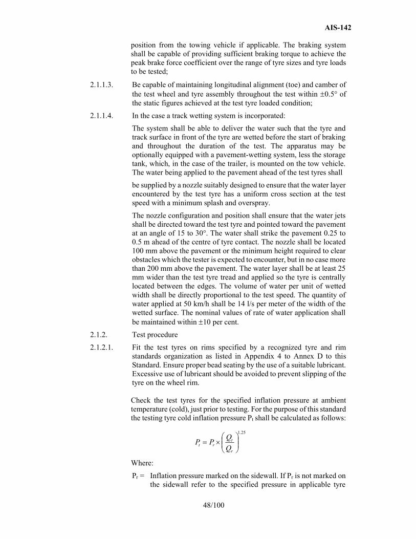
AIS-142
48/100
position from the towing vehicle if applicable. The braking system shall be capable of providing sufficient braking torque to achieve the peak brake force coefficient over the range of tyre sizes and tyre loads to be tested;
2.1.1.3. Be capable of maintaining longitudinal alignment (toe) and camber of the test wheel and tyre assembly throughout the test within 0.5° of the static figures achieved at the test tyre loaded condition;
2.1.1.4. In the case a track wetting system is incorporated:
The system shall be able to deliver the water such that the tyre and track surface in front of the tyre are wetted before the start of braking and throughout the duration of the test. The apparatus may be optionally equipped with a pavement-wetting system, less the storage tank, which, in the case of the trailer, is mounted on the tow vehicle. The water being applied to the pavement ahead of the test tyres shall
be supplied by a nozzle suitably designed to ensure that the water layer encountered by the test tyre has a uniform cross section at the test speed with a minimum splash and overspray.
The nozzle configuration and position shall ensure that the water jets shall be directed toward the test tyre and pointed toward the pavement at an angle of 15 to 30°. The water shall strike the pavement 0.25 to 0.5 m ahead of the centre of tyre contact. The nozzle shall be located 100 mm above the pavement or the minimum height required to clear obstacles which the tester is expected to encounter, but in no case more than 200 mm above the pavement. The water layer shall be at least 25 mm wider than the test tyre tread and applied so the tyre is centrally located between the edges. The volume of water per unit of wetted width shall be directly proportional to the test speed. The quantity of water applied at 50 km/h shall be 14 l/s per meter of the width of the wetted surface. The nominal values of rate of water application shall be maintained within 10 per cent.
2.1.2. Test procedure
2.1.2.1. Fit the test tyres on rims specified by a recognized tyre and rim standards organization as listed in Appendix 4 to Annex D to this Standard. Ensure proper bead seating by the use of a suitable lubricant. Excessive use of lubricant should be avoided to prevent slipping of the tyre on the wheel rim. Check the test tyres for the specified inflation pressure at ambient temperature (cold), just prior to testing. For the purpose of this standard the testing tyre cold inflation pressure Pt shall be calculated as follows:
25.1
r
trt Q
QPP
Where:
Pr = Inflation pressure marked on the sidewall. If Pr is not marked on the sidewall refer to the specified pressure in applicable tyre
AIS-142
49/100
standards manuals corresponding to maximum load capacity for single applications
Qt = The static test load of the tyre
Qr = The maximum mass associated with the load capacity index of the tyre
2.1.2.2. For tyre break-in, two braking runs are performed. The tyre shall be conditioned for a minimum of two hours adjacent to the test track such that it is stabilized at the ambient temperature of the test track area. The tyre(s) shall not be exposed to direct sunshine during conditioning.
2.1.2.3. The load conditions for testing shall be 75 5 per cent of the value corresponding to the load index.
2.1.2.4. Shortly before testing, the track shall be conditioned by carrying out at least ten braking test runs at 50 km/h on the part of the track to be used for the performance test programme but using a tyre not involved in that programme;
2.1.2.5. Immediately prior to testing, the tyre inflation pressure shall be checked and reset, if necessary, to the values given in paragraph 2.1.2.1.
2.1.2.6. The test speed shall be at 50 2 km/h and shall be maintained between these limits throughout the test run.
2.1.2.7. The direction of the test shall be the same for each set of tests and shall be the same for the test tyre as that used for the SRTT with which its performance is to be compared.
2.1.2.8. Deliver water to the pavement ahead of the test tyre approximately 0.5 s prior to brake application (for internal watering system). The brakes of the test wheel assembly shall be applied such that peak braking force is achieved within 0.2 s and 1.0 s of brake application.
2.1.2.9. For new tyres, the first two braking runs are discarded for tyre break-in.
2.1.2.10. For the evaluation of the performance of any tyre compared with that of the SRTT, the braking test should be run at the same area on the test pad.
2.1.2.11. The order of testing shall be:
R1 - T - R2
Where:
R1= the initial test of the SRTT,
R2= the repeat test of the SRTT and
T= the test of the candidate tyre to be evaluated.
A maximum of three candidate tyres may be tested before repeating the SRTT test, for example:
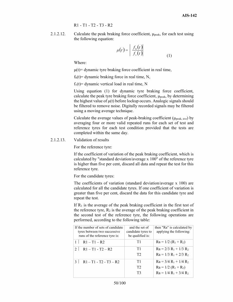
AIS-142
50/100
R1 - T1 - T2 - T3 - R2
2.1.2.12. Calculate the peak braking force coefficient, μpeak, for each test using the following equation:
(1)
Where:
μ(t)= dynamic tyre braking force coefficient in real time,
fh(t)= dynamic braking force in real time, N,
fv(t)= dynamic vertical load in real time, N
Using equation (1) for dynamic tyre braking force coefficient, calculate the peak tyre braking force coefficient, μpeak, by determining the highest value of μ(t) before lockup occurs. Analogic signals should be filtered to remove noise. Digitally recorded signals may be filtered using a moving average technique.
Calculate the average values of peak-braking coefficient (μpeak, ave) by averaging four or more valid repeated runs for each set of test and reference tyres for each test condition provided that the tests are completed within the same day.
2.1.2.13. Validation of results
For the reference tyre:
If the coefficient of variation of the peak braking coefficient, which is calculated by "standard deviation/average x 100" of the reference tyre is higher than five per cent, discard all data and repeat the test for this reference tyre.
For the candidate tyres:
The coefficients of variation (standard deviation/average x 100) are calculated for all the candidate tyres. If one coefficient of variation is greater than five per cent, discard the data for this candidate tyre and repeat the test.
If R1 is the average of the peak braking coefficient in the first test of the reference tyre, R2 is the average of the peak braking coefficient in the second test of the reference tyre, the following operations are performed, according to the following table:
If the number of sets of candidate tyres between two successive runs of the reference tyre is:
and the set of candidate tyres to
be qualified is:
then "Ra" is calculated by applying the following:
1 R1 – T1 – R2 T1 Ra = 1/2 (R1 + R2)
2 R1 – T1 - T2 – R2 T1
T2
Ra = 2/3 R1 + 1/3 R2
Ra = 1/3 R1 + 2/3 R2
3 R1 – T1 - T2 - T3 – R2 T1
T2
T3
Ra = 3/4 R1 + 1/4 R2
Ra = 1/2 (R1 + R2)
Ra = 1/4 R1 + 3/4 R2
tf
tftμ
v
h
AIS-142
51/100
2.1.2.14. The wet grip index (G) shall be calculated as:
Wet grip index (G) = μ peak,ave (T)/μ peak, ave (R)
It represents the relative Wet Grip Index for braking performance of the candidate tyre (T) compared to the reference tyre (R).
2.2. Standard vehicle procedure
2.2.1. The vehicle used shall have two axles and be equipped with an anti-lock braking system (e.g. standard production vehicle of M2, M3, N1, N2 or N3 category). The ABS shall continue to fulfil the utilisation of adhesion requirements defined in the Regulations as appropriate, and shall be comparable and constant throughout the tests with the different tyres mounted.
2.2.1.1. Measuring equipment
The vehicle shall be fitted with a sensor suitable for measuring speed on a wet surface and distance covered between two speeds.
To measure vehicle speed, a fifth wheel or non-contact speed-measuring system shall be used.
The following tolerances shall be respected:
(a) For the speed measurements: ±1 per cent or ±0.5 km/h whichever is greater;
(b) For the distance measurements: ±1 x 10⁻¹ m.
A display of the measured speed or the difference between the measured speed and the reference speed for the test can be used inside the vehicle so that the driver can adjust the speed of the vehicle.
A data acquisition system can be also used for storing the measurements.
2.2.2. Test procedure
Starting with a defined initial speed, the brakes are applied hard enough on the two axles at the same time to activate the ABS system.
2.2.2.1. The Average Deceleration (AD) is calculated between two defined speeds, with an initial speed of 60 km/h and a final speed of 20 km/h.
2.2.2.2. Vehicle equipment
The rear axle may be indifferently fitted with 2 or 4 tyres.
For the reference tyre testing, both axles are fitted with reference tyres. (A total of 4 or 6 reference tyres depending on the choice above mentioned).
For the candidate tyre testing, 3 fitting configurations are possible:
(a) Configuration "Configuration 1": Candidate tyres on front and rear axles: it is the standard configuration that should be used every time it is possible.
AIS-142
52/100
(b) Configuration "Configuration 2": Candidate tyres on front axle and reference tyre or control tyre on rear axle: allowed in such cases where fitting the candidate tyre on the rear position is not possible.
(c) Configuration "Configuration 3": Candidate tyres on rear axle and reference tyre or control tyre on front axle: permitted in such cases where fitting the candidate tyre on the front position is not possible.
2.2.2.3. Tyre inflation pressure
(a) For a vertical load higher or equal to 75 per cent of the load capacity of the tyre, the test inflation pressure "Pt" shall be calculated as follows:
Pt = Pr · (Qt/Qr)1.25
Pr = Inflation pressure marked on the sidewall. If Pr is not marked on the sidewall refer to the specified pressure in applicable tyre standards manuals corresponding to maximum load capacity for single applications
Qt = static test load of the tyre
Qr = maximum mass associated with the load capacity index of the tyre
(c) For a vertical load lower than 75 per cent of the load capacity of the tire, the test inflation pressure Pt shall be calculated as follows:
Pt = Pr · (0.75)1.25 = (0.7) · Pr
Pr = Inflation pressure marked on the sidewall.
If Pr is not marked on the sidewall refer to the specified pressure in applicable tyre standard manuals corresponding to maximum load capacity for single applications.
Check the tyre pressure just prior to testing at ambient temperature.
2.2.2.4. Tyre load
The static load on each axle shall remain the same throughout the test procedure. The static load on each tyre shall lie between 60 per cent and 100 per cent of the candidate tyre's load capacity. This value shall not exceed 100 per cent of the load capacity of the reference tyre.
Tyre load on the same axle should not differ by more than 10 per cent.
The use of fitting as per Configurations 2 and 3 shall fulfil the following additional requirements:
Configuration 2: Front axle load > Rear axle load
The rear axle may be indifferently fitted with 2 or 4 tyres
Configuration 3: Rear axle load > Front axle load x 1.8
AIS-142
53/100
2.2.2.5. Tyre preparation and break-in
2.2.2.5.1. The test tyre shall be mounted on the test rim declared by the tyre manufacturer.
Ensure proper bead seating by the use of a suitable lubricant. Excessive use of lubricant should be avoided to prevent slipping of the tyre on the wheel rim.
2.2.2.5.2. Place the fitted test tyres in a location for a minimum of two hours such that they all have the same ambient temperature prior to testing, and shield them from the sun to avoid excessive heating by solar radiation. For tyre break-in, perform two braking runs.
2.2.2.5.3. Condition the pavement by conducting at least ten test runs with tyres not involved in the test programme at an initial speed higher or equal to 65 km/h (which is higher than the initial test speed to guarantee that a sufficient length of track is conditioned).
2.2.2.6. Procedure
2.2.2.6.1. First, mount the set of reference tyres on the vehicle.
The vehicle accelerates in the starting zone up to 65 ± 2 km/h.
Activation of the brakes on the track is made always at the same place with a tolerance of 5 meters in longitudinal and 0.5 meters in transverse.
2.2.2.6.2. According to the type of transmission, two cases are possible:
(a) Manual transmission
As soon as the driver is in the measuring zone and having reached 65 ± 2 km/h, the clutch is released and the brake pedal depressed sharply, holding it down as long as necessary to perform the measurement.
(b) Automatic transmission
As soon as the driver is in the measuring zone and having reached 65 ± 2 km/h, select neutral gear and then the brake pedal is depressed sharply, holding it down as long as necessary to perform the measurement.
Automatic activation of the brakes can be performed by means of a detection system made of two parts, one indexed to the track and one embarked on the vehicle. In that case braking is made more rigorously at the same portion of the track.
If any of the above-mentioned conditions are not met when a measurement is made (speed tolerance, braking time, etc.), the measurement is discarded and a new measurement is made.
AIS-142
54/100
2.2.2.6.3. Test running order
Examples:
The run order for a test of 3 sets of candidate tyres (T1 to T3) plus a reference tyre R would be:
R - T1 - T2 - T3 - R
The run order for a test of 5 sets of tyres (T1 to T5) plus a reference tyre R would be:
R - T1 - T2 - T3 - R -T4 - T5 – R
2.2.2.6.4. The direction of the test shall be the same for each set of tests and shall be the same for the candidate test tyre as that used for the SRTT with which its performance is to be compared.
2.2.2.6.5. For each test and for new tires, the first two braking measurements are discarded.
2.2.2.6.6. After at least 3 valid measurements have been made in the same direction, the reference tyres are replaced by a set of the candidate tyres (one of the 3 configurations presented in paragraph 2.2.2.2.) and at least 6 valid measurements shall be performed.
2.2.2.6.7. A maximum of three sets of candidate tyres can be tested before the reference tyre is re-tested.
2.2.2.7. Processing of measurement results
2.2.2.7.1. Calculation of the Average Deceleration (AD)
Each time the measurement is repeated, the average deceleration AD [m∙s-²) is calculated by:
Where d [m] is the distance covered between the initial speed Si [m∙s-1] and the final speed Sf [m∙s-1].
2.2.2.7.2. Validation of results For the reference tyre: If the coefficient of variation of "AD" of any two consecutive groups of 3 runs of the reference tyre is higher than 3 per cent, discard all data and repeat the test for all tyres (the candidate tyres and the reference tyre). The coefficient of variation is calculated by the following relation:
For the candidate tyres: The coefficients of variation are calculated for all the candidate tyres.
If one coefficient of variation is greater than 3 per cent, discard the data for this candidate tyre and repeat the test.
d
SSAD if
2
22
100average
deviation standard
100average
deviation standard

AIS-142
55/100
2.2.2.7.3. Calculation of the "average AD" If R1 is the average of the AD values in the first test of the reference tyre and R2 is the average of the AD values in the second test of the reference tyre, the following operations are performed, according to Table 5. Ra is the adjusted average AD of the reference tyre.
Table 5 Number of sets of candidate tyres between two successive
runs of the reference tyre
Set of candidate tyres to be qualified
Ra
1 R1-T1-R2 T1 Ra = 1/2 (R1 + R2) 2 R1-T1-T2-R2 T1
T2 Ra = 2/3 R1 + 1/3 R2 Ra = 1/3 R1 + 2/3 R2
3 R1-T1-T2-T3-R2 T1 T2 T3
Ra = 3/4 R1 + 1/4 R2 Ra = 1/2 (R1 + R2) Ra = 1/4 R1 + 3/4 R2
2.2.2.7.4. Calculation of braking force coefficient, BFC
BFC(R) and BFC(T) are calculated according to Table 6:
Table 6
Tyre type Braking force coefficient is
Reference tyre BFC(R) = Ra/g
Candidate tyre BFC(T) = Ta/g
g is the acceleration due to gravity (rounded to 9.81 m⋅s−2).
Ta (a = 1, 2, etc.) is the average of the AD values for a test of a candidate tyre.
2.2.2.7.5. Calculation of the relative wet grip performance index of the tyre
The Wet grip index represents the relative performance of the candidate tyre compared to the reference tyre. The way to obtain it depends on the test configuration as defined in paragraph 2.2.2.2. of this annex. The wet grip index of the tyre is calculated as reported into Table 7:
Table 7
Configuration C1: candidate tyres on both axles
)R(BFC
)T(BFCIndexGripWet
Configuration C2: candidate tyres on front axle and reference tyres on rear axle
)T(BFChb)R(BFC
)R(BFCa)R(BFChba)T(BFCIndexGripWet
Configuration C3: reference tyres on front axle and candidate tyres on rear axle
)T(BFCha)R(BFC
)R(BFCb)R(BFChba)T(BFCIndexGripWet
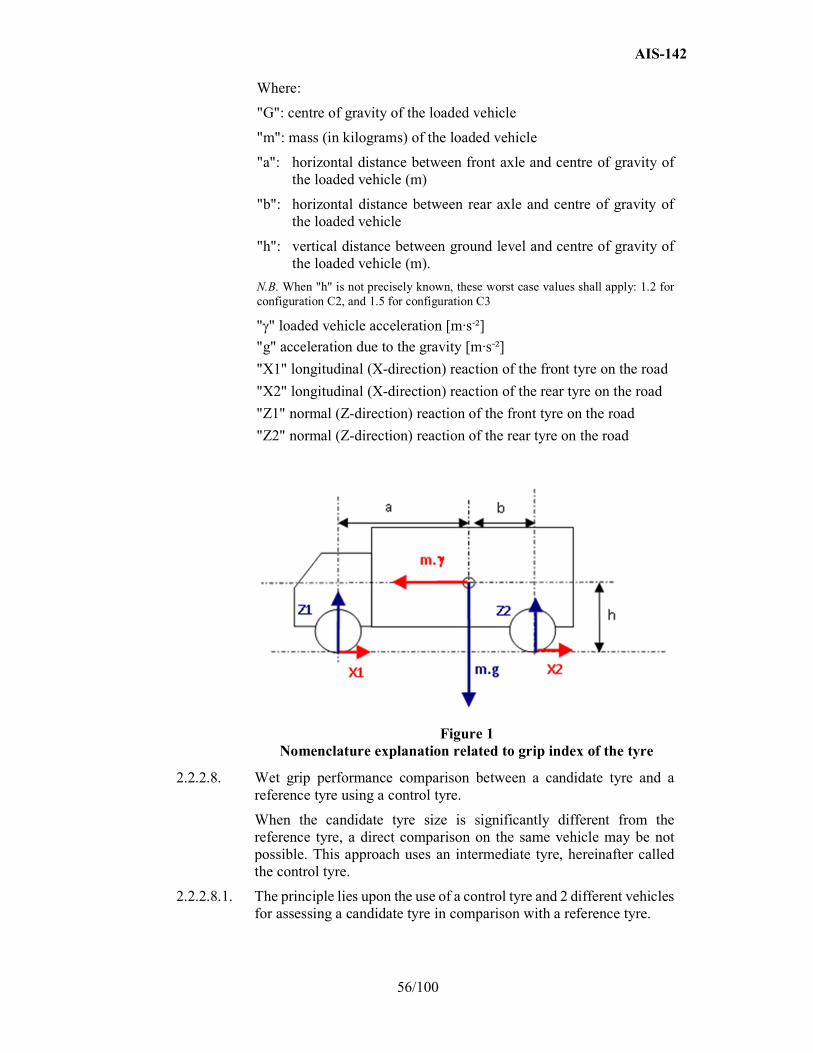
AIS-142
56/100
Where:
"G": centre of gravity of the loaded vehicle
"m": mass (in kilograms) of the loaded vehicle
"a": horizontal distance between front axle and centre of gravity of the loaded vehicle (m)
"b": horizontal distance between rear axle and centre of gravity of the loaded vehicle
"h": vertical distance between ground level and centre of gravity of the loaded vehicle (m).
N.B. When "h" is not precisely known, these worst case values shall apply: 1.2 for configuration C2, and 1.5 for configuration C3
"" loaded vehicle acceleration [m∙s-²]
"g" acceleration due to the gravity [m∙s-²]
"X1" longitudinal (X-direction) reaction of the front tyre on the road
"X2" longitudinal (X-direction) reaction of the rear tyre on the road
"Z1" normal (Z-direction) reaction of the front tyre on the road
"Z2" normal (Z-direction) reaction of the rear tyre on the road
Figure 1 Nomenclature explanation related to grip index of the tyre
2.2.2.8. Wet grip performance comparison between a candidate tyre and a reference tyre using a control tyre.
When the candidate tyre size is significantly different from the reference tyre, a direct comparison on the same vehicle may be not possible. This approach uses an intermediate tyre, hereinafter called the control tyre.
2.2.2.8.1. The principle lies upon the use of a control tyre and 2 different vehicles for assessing a candidate tyre in comparison with a reference tyre.

AIS-142
57/100
One vehicle can fit the reference tyre and the control tyre, the other the control tyre and the candidate tyre. All conditions are in conformity with paragraphs 2.2.1.2. to 2.2.2.5. above.
2.2.2.8.2. The first assessment is a comparison between the control tyre and the reference tyre. The result (Wet Grip Index 1) is the relative efficiency of the control tyre compared to the reference tyre.
2.2.2.8.3. The second assessment is a comparison between the candidate tyre and the control tyre. The result (Wet Grip Index 2) is the relative efficiency of the candidate tyre compared to the control tyre.
The second assessment is done on the same track as the first one and within one week maximum. The wetted surface temperature shall be in the range of +5°C of the temperature of the first assessment. The control tyre set (4 or 6 tyres) is physically the same set as the set used for the first assessment.
2.2.2.8.4. The wet grip index of the candidate tyre compared to the reference tyre is deduced by multiplying the relative efficiencies calculated above:
(Wet Grip Index 1 · Wet Grip Index 2)
Note: When the test expert decides to use an SRTT tyre as a control tyre (i.e. in the test procedure two SRTTs are compared directly instead of an SRTT with a control tyre) the result of the comparison between the SRTTs is called the "local shift factor".
It is permitted to use a previous SRTTs comparison.
The comparison results shall be checked periodically.
2.2.2.8.5. Selection of a set of tyres as a control tyre set
A "control tyre" set is a group of identical tyres made in the same factory during a one week period.
2.2.2.8.6. Reference and control tyres
Before the first assessment (control tyre / reference tyre), normal storage conditions can be used. It is necessary that all the tyres of a control tyre set have been stored in the same conditions.
2.2.2.8.7. Storage of control tyres
As soon as the control tyre set has been assessed in comparison with the reference tyre, specific storage conditions shall be applied for control tyres replacement.
2.2.2.8.8. Replacement of reference and control tyres
When irregular wear or damage results from tests, or when wear influences the test results, the use of the tyre shall be discontinued.

AIS-142
58/100
ANNEX - C
Appendix 1 - Test reports examples of wet grip index
Example 1: Test report of wet grip index using trailer method
Test report number: Test date:
Type of road surface: Texture depth (mm):
µ peak (SRTT14 E1136) : or BPN:
Speed (km/h): Water depth (mm):
No. 1 2 3 4 5 6 7 8 9 10
Size
Service description
Tyre identification
Rim
Pattern
Load (N)
Pressure (kPa)
µpeak 1
2
3
4
5
6
7
8
Average
Standard deviation σ
(σ/average)≤5 per cent
Ra, Adjusted
Wet grip index
Surface temp. (°C)
Ambient temp. (°C)
Remarks
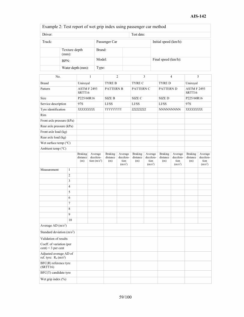
AIS-142
59/100
Example 2: Test report of wet grip index using passenger car method
Driver: Test date:
No. 1 2 3 4 5
Brand Uniroyal TYRE B TYRE C TYRE D Uniroyal
Pattern ASTM F 2493 SRTT16
PATTERN B PATTERN C PATTERN D ASTM F 2493 SRTT16
Size P225/60R16 SIZE B SIZE C SIZE D P225/60R16
Service description 97S LI/SS LI/SS LI/SS 97S
Tyre identification XXXXXXXXX YYYYYYYYY ZZZZZZZZZ NNNNNNNNN XXXXXXXXX
Rim
Front axle pressure (kPa)
Rear axle pressure (kPa)
Front axle load (kg)
Rear axle load (kg)
Wet surface temp (°C)
Ambient temp (°C)
Braking distance
(m)
Average decelera-
tion (m/s2)
Braking distance
(m)
Average decelera-
tion (m/s2)
Braking distance
(m)
Average decelera-
tion (m/s2)
Braking distance
(m)
Average decelera-
tion (m/s2)
Braking distance
(m)
Average decelera-
tion (m/s2)
Measurement 1
2
3
4
5
6
7
8
9
10
Average AD (m/s2)
Standard deviation (m/s2)
Validation of results
Coeff. of variation (per cent) < 3 per cent
Adjusted average AD of ref. tyre: Ra (m/s2)
BFC(R) reference tyre (SRTT16)
BFC(T) candidate tyre
Wet grip index (%)
Track: Passenger Car Initial speed (km/h):
Texture depth (mm):
Brand:
BPN: Model: Final speed (km/h):
Water depth (mm): Type:
AIS-142
60/100
ANNEX - D (See 3.5)
TEST PROCEDURE FOR MEASURING ROLLING RESISTANCE
1.0 Test methods
The alternative measurement methods listed below are given in this Standard. The choice of an individual method is left to the tester. For each method, the test measurements shall be converted to a force acting at the tyre/drum interface. The measured parameters are:
(a) In the force method: the reaction force measured or converted at the tyre spindle;
(b) In the torque method: the torque input measured at the test drum;
(c) In the deceleration method: the measurement of deceleration of the test drum and tyre assembly;
(d) In the power method: the measurement of the power input to the test drum.
2.0 Test equipment
2.1. Drum specifications
2.1.1. Diameter
The test dynamometer shall have a cylindrical flywheel (drum) with a diameter of at least 1.7 m.
The Fr and Cr values shall be expressed relative to a drum diameter of 2.0 m. If drum diameter different than 2.0 m is used, a correlation adjustment shall be made following the method in paragraph 6.3. of this annex.
2.1.2 Surface
The surface of the drum shall be smooth steel. Alternatively, in order to improve skim test reading accuracy, a textured surface may also be used, which should be kept clean.
The Fr and Cr values shall be expressed relative to the "smooth" drum surface. If a textured drum surface is used, see Appendix 1, paragraph 7.
2.1.3. Width
The width of the drum test surface shall exceed the width of the test tyre contact patch.
2.2 Measuring rim (see Appendix 2)
The tyre shall be mounted on a steel or light alloy measuring rim, as follows:
(a) For Class C1 tyres, the width of the rim shall be as defined in ISO 4000-1:2010,
AIS-142
61/100
(b) For Class C2 and C3 tyres, the width of the rim shall be as defined in ISO 4209 1:2001.
In cases where the width is not defined in the above mentioned ISO Standards, the rim width as defined by one of the standards organizations as specified in Appendix 4 may be used.
2.3. Load, alignment, control and instrumentation accuracies
Measurement of these parameters shall be sufficiently accurate and precise to provide the required test data. The specific and respective values are shown in Appendix 1.
2.4. Thermal environment
2.4.1. Reference conditions
The reference ambient temperature, measured at a distance not less than 0.15 m and not more than 1 m from the tyre sidewall, shall be 25 C.
2.4.2 Alternative conditions
If the test ambient temperature is different from the reference ambient temperature, the rolling resistance measurement shall be corrected to the reference ambient temperature in accordance with paragraph 6.2. of this annex.
2.4.3 Drum surface temperature.
Care should be taken to ensure that the temperature of the test drum surface is the same as the ambient temperature at the beginning of the test.
3.0 Test conditions
3.1. General
The test consists of a measurement of rolling resistance in which the tyre is inflated and the inflation pressure allowed to build up, i.e., "capped air".
3.2. Test speeds The value shall be obtained at the appropriate drum speed specified in Table 1.
Table 1 Test Speeds (in km/h)
Tyre Class C1 C2 and C3 C3
Load index All LI ≤ 121 LI > 121
Speed symbol
All All J 100 km/h and lower or tyres not marked with speed symbol
K 110 km/h and higher
Speed 80 80 60 80

AIS-142
62/100
3.3. Test load
The standard test load shall be computed from the values shown in Table 2 and shall be kept within the tolerance specified in Appendix 1.
3.4. Test inflation pressure
The inflation pressure shall be in accordance with that shown in Table 2 and shall be capped with the accuracy specified in paragraph 4. of Appendix 1 to this annex.
Table 2 Test loads and inflation pressures
Tyre Class C1 (a) C2, C3
Standard load
Reinforced or extra load
Load- % of maximum load capacity
80
80
85(b)
(% of single load)
Inflation pressure kPa
210
250
Corresponding to maximum load
capacity for single application(c)
Note:The inflation pressure shall be capped with the accuracy specified in paragraph 4. of Appendix 1 to this annex.
(a) For those passenger car tyres belonging to categories which are not shown in ISO 4000-1:2010, the inflation pressure shall be the inflation pressure recommended by the tyre manufacturer, corresponding to the maximum tyre load capacity, reduced by 30 kPa.
(b) As a percentage of single load, or 85 per cent of maximum load capacity
for single application specified in applicable tyre standards manuals if not marked on tyre.
(c) Inflation pressure marked on sidewall, or if not marked on sidewall, as
specified in applicable tyre standards manuals corresponding to maximum load capacity for single application.
3.5. Duration and speed.
When the deceleration method is selected, the following requirements apply:
(a) The deceleration j shall be determined in exact dω/dt or approximate Δω/Δt form, where ω is angular velocity, t – time;
If the differential form dω/dt is used, then the recommendations of Appendix 5 to this annex are to be applied.
(b) For duration Δt, the time increments shall not exceed 0.5 s;
(c) Any variation of the test drum speed shall not exceed 1 km/h within one time increment.
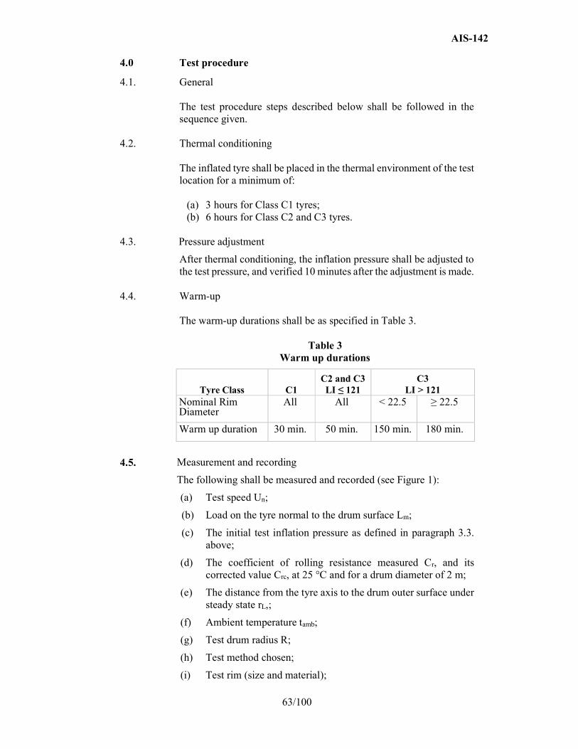
AIS-142
63/100
4.0 Test procedure
4.1. General The test procedure steps described below shall be followed in the sequence given.
4.2. Thermal conditioning The inflated tyre shall be placed in the thermal environment of the test location for a minimum of:
(a) 3 hours for Class C1 tyres; (b) 6 hours for Class C2 and C3 tyres.
4.3. Pressure adjustment
After thermal conditioning, the inflation pressure shall be adjusted to the test pressure, and verified 10 minutes after the adjustment is made.
4.4. Warm-up The warm-up durations shall be as specified in Table 3.
Table 3 Warm up durations
Tyre Class C1 C2 and C3 LI ≤ 121
C3 LI > 121
Nominal Rim Diameter
All All < 22.5 ≥ 22.5
Warm up duration 30 min. 50 min. 150 min. 180 min.
4.5. Measurement and recording
The following shall be measured and recorded (see Figure 1):
(a) Test speed Un;
(b) Load on the tyre normal to the drum surface Lm;
(c) The initial test inflation pressure as defined in paragraph 3.3. above;
(d) The coefficient of rolling resistance measured Cr, and its corrected value Crc, at 25 °C and for a drum diameter of 2 m;
(e) The distance from the tyre axis to the drum outer surface under steady state rL,;
(f) Ambient temperature tamb;
(g) Test drum radius R;
(h) Test method chosen;
(i) Test rim (size and material);
AIS-142
64/100
(j) Tyre size, manufacturer, type, identity number (if one exists), speed symbol, load index, DOT number (Department of Transportation).
Figure 1
All the mechanical quantities (forces, torques) will be orientated in accordance with the axis systems specified in ISO 8855:1991.
The directional tyres shall be run in their specified rotation sense.
4.6 Measurement of parasitic losses
The parasitic losses shall be determined by one of the following procedures given in paragraph 4.6.1. or 4.6.2. below.
4.6.1. Skim test reading
Skim test reading follows the procedure below:
(a) Reduce the load to maintain the tyre at the test speed without slippage.
The load values should be as follows:
(i) Class C1 tyres: recommended value of 100 N; not to exceed 200 N;
(ii) Class C2 tyres: recommended value of 150 N; not to exceed 200 N for machines designed for Class C1 tyre measurement or 500 N for machine designed for Class C2 and C3 tyres;
(iii) Class C3 tyres: recommended value of 400 N; not to exceed 500 N.
(b) Record the spindle force Ft, input torque Tt, or the power, whichever applies;
(c) Record the load on the tyre normal to the drum surface Lm.
4.6.2. Deceleration method
The deceleration method follows the procedure below:
(a) Remove the tyre from the test surface;
AIS-142
65/100
(b) Record the deceleration of the test drum Do/ t and that of the unloaded tyre T0/ t or record the deceleration of the test drum jD0 and that of the unloaded tyre jT0 in exact or approximate form in accordance with paragraph 3.5. above.
4.7. Allowance for machines exceeding σm criterion
The steps described in paragraphs 4.3. to 4.5. above shall be carried out once only, if the measurement standard deviation determined in accordance with paragraph 6.5. below is:
(a) Not greater than 0.075 N/kN for Class C1 and C2 tyres;
(b) Not greater than 0.06 N/kN for Class C3 tyres.
If the measurement standard deviation exceeds this criterion, the measurement process will be repeated n times as described in paragraph 6.5. below. The rolling resistance value reported shall be the average of the n measurements.
5.0 Data interpretation
5.1. Determination of parasitic losses
5.1.1. General The laboratory shall perform the measurements described in paragraph 4.6.1. above for the force, torque and power methods or those described in paragraph 4.6.2. above for the deceleration method, in order to determine precisely in the test conditions (load, speed, temperature) the tyre spindle friction, the tyre and wheel aerodynamic losses, the drum (and as appropriate, engine and/or clutch) bearing friction, and the drum aerodynamic losses. The parasitic losses related to the tyre/drum interface Fpl expressed in newton shall be calculated from the force Ft torque, power or the deceleration, as shown in paragraphs 5.1.2. to 5.1.5. below.
5.1.2 Force method at tyre spindle
Calculate: Fpl = Ft (1 rL/R)
Where:
Ft is the tyre spindle force in newton (see paragraph 4.6.1. above),
rL is the distance from the tyre axis to the drum outer surface under steady state conditions, in metre,
R is the test drum radius, in meter.
5.1.3. Torque method at drum axis
Calculate: Fpl = Tt/R
Where:
Tt is the input torque in newton meter, as determined in paragraph 4.6.1,
R is the test drum radius, in meter.

AIS-142
66/100
5.1.4 Power method at drum axis
Calculate:
Where:
V is the electrical potential applied to the machine drive, in volt, A is the electric current drawn by the machine drive, in ampere, Un is the test drum speed, in kilometer per hour.
5.1.5. Deceleration method
Calculate the parasitic losses Fpl, in newton.
Where:
ID is the test drum inertia in rotation, in kilogram meter squared,
R is the test drum surface radius, in meter,
D0 is the test drum angular speed, without tyre, in radians per second,
t0 is the time increment chosen for the measurement of the parasitic losses without tyre, in second,
IT is the spindle, tyre and wheel inertia in rotation, in kilogram meter squared,
Rr is the tyre rolling radius, in metre, T0 is the tyre angular speed, unloaded tyre, in radian per
second.
or
T0r
TD0
Dpl j
R
Ij
R
IF
Where:
ID is the test drum inertia in rotation, in kilogram meter squared,
R is the test drum surface radius, in meter,
jD0 is the deceleration of the test drum, without tyre, in radians per second squared,
IT is the spindle, tyre and wheel inertia in rotation, in kilogram meter squared,
Rr is the tyre rolling radius, in metre,
jT0 is the deceleration of unloaded tyre, in radians per second squared.
0
0
0
0
R
I
t R
I F
T
r
T DDpl
pl n
3,6 V x AF
U
AIS-142
67/100
5.2. Rolling resistance calculation
5.2.1. General
The rolling resistance Fr, expressed in newton, is calculated using the values obtained by testing the tyre to the conditions specified in this international standard and by subtracting the appropriate parasitic losses Fpl, obtained according to paragraph 5.1. above.
5.2.2 Force method at tyre spindle
The rolling resistance Fr, in newton, is calculated using the equation
Fr = Ft[1 (rL/R)] Fpl
Where:
Ft is the tyre spindle force in newton,
Fpl represents the parasitic losses as calculated in paragraph 5.1.2. above,
rL is the distance from the tyre axis to the drum outer surface under steady-state conditions, in metre,
R is the test drum radius, in metre.
5.2.3. Torque method at drum axis
The rolling resistance Fr, in newton, is calculated with the equation
Where:
Tt is the input torque, in newton metre,
Fp
l represents the parasitic losses as calculated in
paragraph 5.1.3. above,
R is the test drum radius, in metre.
5.2.4. Power method at drum axis
The rolling resistance Fr, in newton, is calculated with the equation:
Where:
V is the electrical potential applied to the machine drive, in volt,
A is the electric current drawn by the machine drive, in ampere,
Un is the test drum speed, in kilometre per hour,
Fpl represents the parasitic losses as calculated in paragraph 5.1.4. above.
tr pl
TF F
R
r pln
3,6V AF F
U
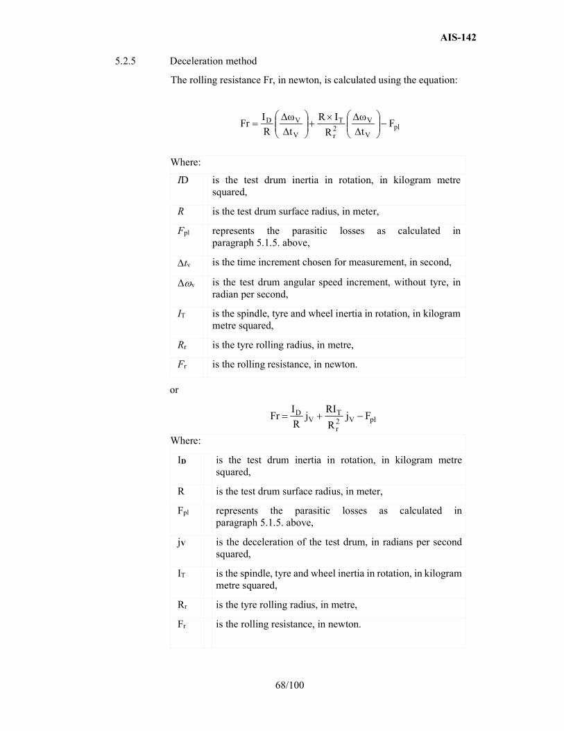
AIS-142
68/100
5.2.5 Deceleration method
The rolling resistance Fr, in newton, is calculated using the equation:
plV
V2r
T
V
VD Ft
ω
R
IR
t
ω
R
IFr
Where:
ID is the test drum inertia in rotation, in kilogram metre squared,
R is the test drum surface radius, in meter,
Fpl represents the parasitic losses as calculated in paragraph 5.1.5. above,
tv is the time increment chosen for measurement, in second,
Δv is the test drum angular speed increment, without tyre, in radian per second,
IT is the spindle, tyre and wheel inertia in rotation, in kilogram metre squared,
Rr is the tyre rolling radius, in metre,
Fr is the rolling resistance, in newton.
or
plV2r
TV
D FjR
RIj
R
IFr
Where:
ID is the test drum inertia in rotation, in kilogram metre squared,
R is the test drum surface radius, in meter,
Fpl represents the parasitic losses as calculated in paragraph 5.1.5. above,
jV is the deceleration of the test drum, in radians per second squared,
IT is the spindle, tyre and wheel inertia in rotation, in kilogram metre squared,
Rr is the tyre rolling radius, in metre,
Fr is the rolling resistance, in newton.
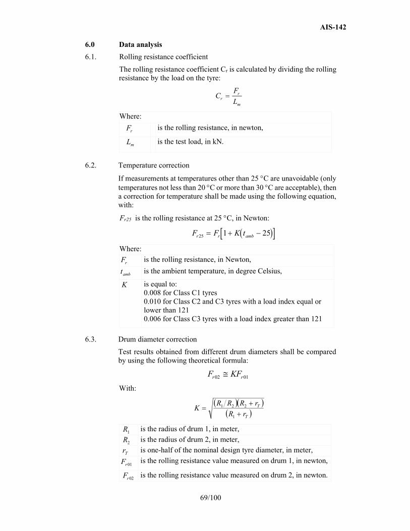
AIS-142
69/100
6.0 Data analysis
6.1. Rolling resistance coefficient
The rolling resistance coefficient Cr is calculated by dividing the rolling resistance by the load on the tyre:
Where:
is the rolling resistance, in newton,
is the test load, in kN.
6.2. Temperature correction
If measurements at temperatures other than 25 C are unavoidable (only temperatures not less than 20 C or more than 30 C are acceptable), then a correction for temperature shall be made using the following equation, with:
Fr25 is the rolling resistance at 25 C, in Newton:
Where:
is the rolling resistance, in Newton,
is the ambient temperature, in degree Celsius,
is equal to: 0.008 for Class C1 tyres 0.010 for Class C2 and C3 tyres with a load index equal or lower than 121 0.006 for Class C3 tyres with a load index greater than 121
6.3. Drum diameter correction
Test results obtained from different drum diameters shall be compared by using the following theoretical formula:
With:
is the radius of drum 1, in meter,
is the radius of drum 2, in meter,
is one-half of the nominal design tyre diameter, in meter,
is the rolling resistance value measured on drum 1, in newton,
is the rolling resistance value measured on drum 2, in newton.
CF
Lrr
m
Fr
Lm
F F K tr r amb25 1 25
Fr
tamb
K
F KFr r02 01
T
T
rR
rRRRK
1
221
R1
R2
rT
01rF
Fr02
AIS-142
70/100
6.4. Measurement result
Where n measurements are greater than 1, if required by paragraph 4.6. above, the measurement result shall be the average of the Cr values obtained for the n measurements, after the corrections described in paragraphs 6.2. and 6.3. above have been made.
6.5. The laboratory shall ensure that, based on a minimum of three measurements, the machine maintains the following values of σm, as measured on a single tyre:
σm ≤ 0.075 N/kN for tyres of Classes C1 and C2
σm ≤ 0.06 N/kN for tyres of Class C3
If the above requirement for σm is not met, the following formula shall be applied to determine the minimum number of measurements n (rounded to the immediate superior integer value) that are required by the machine to qualify for conformance with this Standard.
n = (σm/ x)²
Where:
x = 0.075 N/kN for tyres of Classes C1 and C2
x = 0.06 N/kN for tyres of Class C3
If a tyre needs to be measured several times, the tyre/wheel assembly shall be removed from the machine between the successive measurements.
If the removal/refitting operation duration is less than 10 minutes, the warm-up durations indicated in paragraph 4.3. above may be reduced to:
(a) 10 minutes for tyres of Class C1;
(b) 20 minutes for tyres of Class C2;
(c) 30 minutes for tyres of Class C3.
6.6 Monitoring of the laboratory control tyre shall be carried out at intervals no greater than one month. Monitoring shall include a minimum of 3 separate measurements taken during this one month period. The average of the 3 measurements taken during a given one-month period shall be evaluated for drift from one monthly evaluation to another.
AIS-142
71/100
ANNEX – D Appendix - 1
(See 2.1.2, 2.3, 3.3, and 3.4 of ANNEX D)
Test equipment tolerances
1.0 Purpose
The limits specified in this annex are necessary in order to achieve suitable levels of repeatable test results, which can also be correlated among various test laboratories. These tolerances are not meant to represent a complete set of engineering specifications for test equipment; rather, they should serve as guidelines for achieving reliable test results.
2.0 Test rims
2.1. Width
For passenger car tyre rims (C1 tyres), the test rim width shall be the same as the measuring rim determined in ISO 4000-1: 2010 clause 6.2.2.
For truck and bus tyres (C2 and C3), the rim width shall be the same as the measuring rim determined in ISO 4209-1:2001, clause 5.1.3.
In cases where the width is not defined in the above mentioned ISO Standards, the rim width as defined by one of the standards organizations as specified in Appendix 4 to Annex D may be used.
2.2. Run-out
Run-out shall meet the following criteria:
(a) Maximum radial run-out: 0.5 mm;
(b) Maximum lateral run-out: 0.5 mm.
3.0 Drum / tyre alignment
General:
Angle deviations are critical to the test results.
3.1. Load application
The direction of tyre loading application shall be kept normal to the test surface and shall pass through the wheel centre within
(a) 1 mrad for the force and deceleration methods;
(b) 5 mrad for the torque and power methods.
3.2. Tyre alignment
3.2.1. Camber angle
The plane of the wheel shall be perpendicular to the test surface within 2 mrad for all methods.
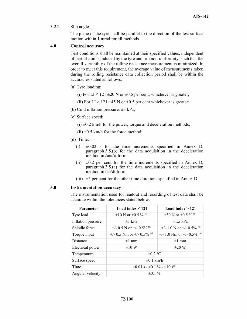
AIS-142
72/100
3.2.2. Slip angle
The plane of the tyre shall be parallel to the direction of the test surface motion within 1 mrad for all methods.
4.0 Control accuracy
Test conditions shall be maintained at their specified values, independent of perturbations induced by the tyre and rim non-uniformity, such that the overall variability of the rolling resistance measurement is minimized. In order to meet this requirement, the average value of measurements taken during the rolling resistance data collection period shall be within the accuracies stated as follows:
(a) Tyre loading:
(i) For LI ≤ 121 ±20 N or ±0.5 per cent, whichever is greater;
(ii) For LI > 121 ±45 N or ±0.5 per cent whichever is greater;
(b) Cold inflation pressure: ±3 kPa;
(c) Surface speed:
(i) ±0.2 km/h for the power, torque and deceleration methods;
(ii) ±0.5 km/h for the force method;
(d) Time:
(i) ±0.02 s for the time increments specified in Annex D, paragraph 3.5.(b) for the data acquisition in the deceleration method in ∆ω/∆t form;
(ii) ±0.2 per cent for the time increments specified in Annex D, paragraph 3.5.(a) for the data acquisition in the deceleration method in dω/dt form;
(iii) ±5 per cent for the other time durations specified in Annex D.
5.0 Instrumentation accuracy
The instrumentation used for readout and recording of test data shall be accurate within the tolerances stated below:
Parameter Load index ≤ 121 Load index > 121
Tyre load ±10 N or ±0.5 % (a) ±30 N or ±0.5 % (a)
Inflation pressure ±1 kPa ±1.5 kPa
Spindle force +/- 0.5 N or +/- 0.5% (a) +/- 1.0 N or +/- 0.5% (a)
Torque input +/- 0.5 Nm or +/- 0.5% (a) +/- 1.0 Nm or +/- 0.5% (a)
Distance ±1 mm ±1 mm
Electrical power ±10 W ±20 W
Temperature ±0.2 °C
Surface speed ±0.1 km/h
Time ±0.01 s - ±0.1 % - ±10 s(b)
Angular velocity ±0.1 %
AIS-142
73/100
(a) Whichever is greater.
(b) ±0.01 s for the time increments specified in Annex D, paragraph 3.5.(b) for the data acquisition in the deceleration method in ∆ω/∆t form ±0.1 per cent for the time increments specified in Annex D, paragraph 3.5.(a) for the data acquisition in the deceleration method in dω/dt form ± 10 sec for the other time durations specified in Annex D.
6.0 Compensation for load/spindle force interaction and load misalignment
for the force method only
Compensation of both load/spindle force interaction ("cross talk") and load misalignment may be achieved either by recording the spindle force for both forward and reverse tyre rotation or by dynamic machine calibration. If spindle force is recorded for forward and reverse directions (at each test condition), compensation is achieved by subtracting the "reverse" value from the "forward" value and dividing the result by two. If dynamic machine calibration is intended, the compensation terms may be easily incorporated in the data reduction.
In cases where reverse tyre rotation immediately follows the completion of the forward tyre rotation, a warm-up time for reverse tyre rotation shall be at least 10 minutes for Class C1 tyres and 30 minutes for all other tyre types.
7.0 Test surface roughness
The roughness, measured laterally, of the smooth steel drum surface shall have a maximum centreline average height value of 6.3 m. Note: In cases where a textured drum surface is used instead of a smooth steel surface, this fact is noted in the test report. The surface texture shall then be 180 m deep (80 grit) and the laboratory is responsible for maintaining the surface roughness characteristics. No specific correction factor is recommended for cases where a textured drum surface is used.
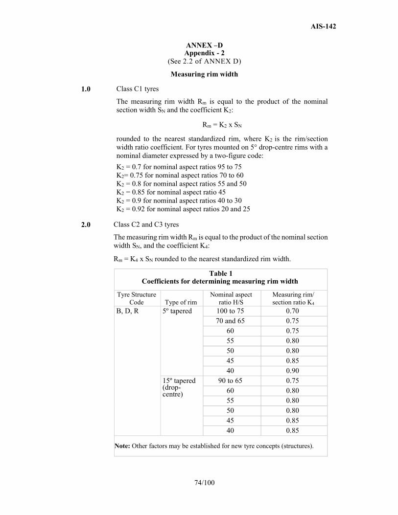
AIS-142
74/100
ANNEX –D Appendix - 2
(See 2.2 of ANNEX D)
Measuring rim width
1.0 Class C1 tyres
The measuring rim width Rm is equal to the product of the nominal section width SN and the coefficient K2:
Rm = K2 x SN
rounded to the nearest standardized rim, where K2 is the rim/section width ratio coefficient. For tyres mounted on 5° drop-centre rims with a nominal diameter expressed by a two-figure code:
K2 = 0.7 for nominal aspect ratios 95 to 75 K2= 0.75 for nominal aspect ratios 70 to 60 K2 = 0.8 for nominal aspect ratios 55 and 50 K2 = 0.85 for nominal aspect ratio 45 K2 = 0.9 for nominal aspect ratios 40 to 30 K2 = 0.92 for nominal aspect ratios 20 and 25
2.0 Class C2 and C3 tyres
The measuring rim width Rm is equal to the product of the nominal section width SN, and the coefficient K4:
Rm = K4 x SN rounded to the nearest standardized rim width.
Table 1 Coefficients for determining measuring rim width
Tyre Structure Code Type of rim
Nominal aspect ratio H/S
Measuring rim/ section ratio K4
B, D, R 5º tapered 100 to 75 0.70 70 and 65 0.75
60 0.75 55 0.80 50 0.80 45 0.85 40 0.90
15º tapered (drop-centre)
90 to 65 0.75 60 0.80 55 0.80 50 0.80 45 0.85 40 0.85
Note: Other factors may be established for new tyre concepts (structures).

AIS-142
75/100
ANNEX –D Appendix - 3
Test report and test data (Rolling resistance)
Part 1: Report
1. Testing Agency: ………………………………………………………………….
2. Name and address of applicant: …………………………………………………
3. Test report No.:…………………………………………………………………….
4. Manufacturer and brand name or trade description: ………………………………..
5. Tyre class (C1, C2 or C3): ………………………………………………………….
6. Category of use: …………………………………………………………………….
7. Rolling resistance coefficient (temperature and drum diameter corrected): ……………………………………..
8. Comments (if any): ……………………………………………………………….
9. Date: ……………………………………………………………………………….
10. Signature: …………………………………………………………………………..
Part 2: Test data
1. Date of test: ………………………………………………………………………..
2. Test machine identification and drum diameter/surface: ………………………….
3. Test tyre details: …………………………………………………………………..
3.1. Tyre size designation and service description: …………………………………..
3.2. Tyre brand and trade description: ………………………………………………..
3.3. Reference inflation pressure: ………………………………………………kPa
4. Test data: ……………………………………………………………………….
4.1. Measurement method: …………………………………………………………
4.2. Test speed: …………………………………………………………………km/h
4.3. Load: …………………………………………………………………………..N
4.4. Test inflation pressure, initial: …………………………………………………
4.5. Distance from the tyre axis to the drum outer surface under steady state conditions, rL: ….………………………………………………………………………….m
4.6. Test rim width and material: ……………………………………………………
4.7. Ambient temperature: …………………………………………………………..°C
4.8. Skim test load (except deceleration method): ………………………………….N
5. Rolling resistance coefficient: …………………………………………………..
5.1. Initial value (or average in the case of more than 1): ………………………..N/kN
5.2. Temperature corrected N/kN: …………………………………………………..
5.3. Temperature and drum diameter corrected: …………………………………..N/kN

AIS-142
76/104
ANNEX – D Appendix - 4
(See 2.2 of ANNEX D)
Tyre standards organizations
1. The Tire and Rim Association, Inc. (TRA)
2. The European Tyre and Rim Technical Organisation (ETRTO)
3. The Japan Automobile Tyre Manufacturers’ Association (JATMA)
4. The Tyre and Rim Association of Australia (TRAA)
5. South Africa Bureau of Standards (SABS)
6. China Association for Standardization (CAS)
7. Indian Tyre Technical Advisory Committee (ITTAC)
8. International Standards Organisation (ISO)

AIS-142
77/100
ANNEX-D
Appendix-5
Deceleration method: Measurements and data processing for deceleration value obtaining in differential form dω/dt.
1.0 Record dependency "distance-time" of rotating body decelerated from peripheral with a speed range such as 82 to 78 km/h or 62 to 58 km/h dependent on tyre class (Annex D, paragraph 3.2., Table 1) in a discrete form (Figure 1) for a rotating body:
z = f(tz)
Where:
z is a number of body revolutions during deceleration;
tz is end time of revolution number z in seconds recorded with 6 digits after zero.
Figure 1
Note 1:The lower speed of the recording range may be reduced down to 60 km/h when test speed is 80 km/h and 40 km/h when the test speed is 60 km/h.
2.0 Approximate recorded dependency by continuous, monotonic, differentiable function:
2.1. Choose the value nearest to the maximum of z dividable by 4 and divide it into 4 equal parts with bounds: 0, z1(t1), z2(t2), z3(t3), z4(t4).
2.2. Work out the system for 4 equations each of the form:
BTcos
)tT(BcoslnAz m
m
Where unknowns:
A is a dimensionless constant, B is a constant in revolutions per second, TΣ is a constant in seconds, m is the number of bounds shown in figure 1. Insert in these 4 equations the coordinates of 4-th bound above.
0 t t t t
z
41t 2 3
z
z
z4
1z
2
3
1
2
3
4
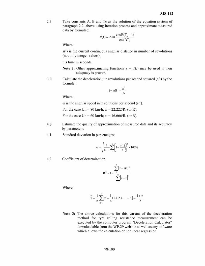
AIS-142
78/100
2.3. Take constants A, B and TΣ as the solution of the equation system of paragraph 2.2. above using iteration process and approximate measured data by formulae:
BTcos
)tT(BcoslnA)t(z
Where:
z(t) is the current continuous angular distance in number of revolutions (not only integer values);
t is time in seconds.
Note 2: Other approximating functions z = f(tz) may be used if their adequacy is proven.
3.0 Calculate the deceleration j in revolutions per second squared (s-2) by the formula:
AABj
22
Where:
ω is the angular speed in revolutions per second (s-1).
For the case Un = 80 km/h; ω = 22.222/Rr (or R).
For the case Un = 60 km/h; ω = 16.666/Rr (or R).
4.0 Estimate the quality of approximation of measured data and its accuracy by parameters:
4.1. Standard deviation in percentages:
%100z
)t(z1
1n
1 n
1
2
4.2. Coefficient of determination
n
1
2
n
1
2
2
zz
)t(zz
1R
Where:
2
n1n21
n
1z
n
1z
n
1z
Note 3: The above calculations for this variant of the deceleration method for tyre rolling resistance measurement can be executed by the computer program "Deceleration Calculator" downloadable from the WP.29 website as well as any software which allows the calculation of nonlinear regression.
AIS-142
79/100
ANNEX - E
(See 3.5)
PROCEDURES FOR SNOW PERFORMANCE TESTING RELATIVE TO SNOW TYRE FOR USE IN SEVERE SNOW CONDITIONS
1.0 Specific definitions for snow test when different from existing ones
1.1. "Test run" means a single pass of a loaded tyre over a given test surface.
1.2. "Braking test" means a series of a specified number of ABS-braking test runs of the same tyre repeated within a short time frame.
1.3. "Traction test" means a series of a specified number of spin-traction test runs according to ASTM standard F1805-06 of the same tyre repeated within a short time frame.
1.4. "Acceleration test" means a series of specified number of traction controlled acceleration test runs of the same tyre repeated within a short timeframe.
2.0 Spin traction method for Classes C1 and C2 tyres (traction force test per paragraph 6.4. (b) of this Standard) The test procedure of ASTM standard F1805-06 shall be used to assess snow performance through spin traction values on medium packed snow (The snow compaction index measured with a CTI penetrometer shall be between 70 and 80).
2.1. The test course surface shall be composed of a medium packed snow surface, as characterized in table A2.1 of ASTM standard F1805-06.
2.2. The tyre load for testing shall be as per option 2 in paragraph 11.9.2. of ASTM standard F1805-06.
3.0 Braking on snow method for Classes C1 and C2 tyres
3.1. General conditions
3.1.1. Test course The braking tests shall be done on a flat test surface of sufficient length and width, with a maximum 2 per cent gradient, covered with packed snow. The snow surface shall be composed of a hard packed snow base at least 3 cm thick and a surface layer of medium packed and prepared snow about 2 cm thick. The air temperature, measured about one meter above the ground, shall be between -2 °C and -15 °C; the snow temperature, measured at a depth of about one centimetre, shall be between 4 °C and -15 °C. It is recommended to avoid direct sunlight, large variations of sunlight or humidity, as well as wind.
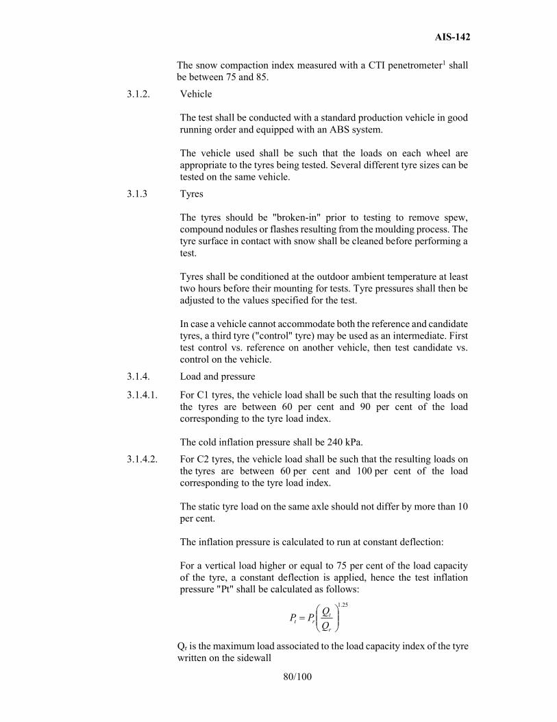
AIS-142
80/100
The snow compaction index measured with a CTI penetrometer1 shall be between 75 and 85.
3.1.2. Vehicle The test shall be conducted with a standard production vehicle in good running order and equipped with an ABS system. The vehicle used shall be such that the loads on each wheel are appropriate to the tyres being tested. Several different tyre sizes can be tested on the same vehicle.
3.1.3 Tyres The tyres should be "broken-in" prior to testing to remove spew, compound nodules or flashes resulting from the moulding process. The tyre surface in contact with snow shall be cleaned before performing a test. Tyres shall be conditioned at the outdoor ambient temperature at least two hours before their mounting for tests. Tyre pressures shall then be adjusted to the values specified for the test. In case a vehicle cannot accommodate both the reference and candidate tyres, a third tyre ("control" tyre) may be used as an intermediate. First test control vs. reference on another vehicle, then test candidate vs. control on the vehicle.
3.1.4. Load and pressure
3.1.4.1. For C1 tyres, the vehicle load shall be such that the resulting loads on the tyres are between 60 per cent and 90 per cent of the load corresponding to the tyre load index. The cold inflation pressure shall be 240 kPa.
3.1.4.2. For C2 tyres, the vehicle load shall be such that the resulting loads on the tyres are between 60 per cent and 100 per cent of the load corresponding to the tyre load index. The static tyre load on the same axle should not differ by more than 10 per cent. The inflation pressure is calculated to run at constant deflection: For a vertical load higher or equal to 75 per cent of the load capacity of the tyre, a constant deflection is applied, hence the test inflation pressure "Pt" shall be calculated as follows:
Qr is the maximum load associated to the load capacity index of the tyre written on the sidewall
25.1
r
trt Q
QPP
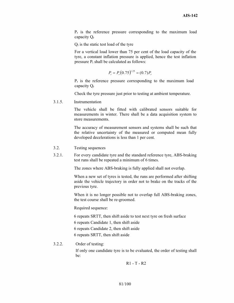
AIS-142
81/100
Pr is the reference pressure corresponding to the maximum load capacity Qr
Qt is the static test load of the tyre
For a vertical load lower than 75 per cent of the load capacity of the tyre, a constant inflation pressure is applied, hence the test inflation pressure Pt shall be calculated as follows:
Pr is the reference pressure corresponding to the maximum load capacity Qr
Check the tyre pressure just prior to testing at ambient temperature.
3.1.5. Instrumentation
The vehicle shall be fitted with calibrated sensors suitable for measurements in winter. There shall be a data acquisition system to store measurements.
The accuracy of measurement sensors and systems shall be such that the relative uncertainty of the measured or computed mean fully developed decelerations is less than 1 per cent.
3.2. Testing sequences
3.2.1. For every candidate tyre and the standard reference tyre, ABS-braking test runs shall be repeated a minimum of 6 times.
The zones where ABS-braking is fully applied shall not overlap.
When a new set of tyres is tested, the runs are performed after shifting aside the vehicle trajectory in order not to brake on the tracks of the previous tyre.
When it is no longer possible not to overlap full ABS-braking zones, the test course shall be re-groomed.
Required sequence:
6 repeats SRTT, then shift aside to test next tyre on fresh surface
6 repeats Candidate 1, then shift aside
6 repeats Candidate 2, then shift aside
6 repeats SRTT, then shift aside
3.2.2. Order of testing:
If only one candidate tyre is to be evaluated, the order of testing shall be:
R1 - T - R2
rrt PPP )7.0(75.0 25.1
AIS-142
82/100
Where:
R1is the initial test of the SRTT, R2 is the repeat test of the SRTT and T is the test of the candidate tyre to be evaluated.
A maximum of two candidate tyres may be tested before repeating the SRTT test, for example:
R1 - T1 - T2 - R2.
3.2.3. The comparative tests of SRTT and candidate tyres shall be repeated on two different days.
3.3. Test procedure
3.3.1. Drive the vehicle at a speed not lower than 28 km/h.
3.3.2. When the measuring zone has been reached, the vehicle gear is set into neutral, the brake pedal is depressed sharply by a constant force sufficient to cause operation of the ABS on all wheels of the vehicle and to result in stable deceleration of the vehicle and held down until the speed is lower than 8 km/h.
3.3.3. The mean fully developed deceleration between 25 km/h and 10 km/h shall be computed from time, distance, speed, or acceleration measurements.
3.4. Data evaluation and presentation of results
3.4.1. Parameters to be reported
3.4.1.1. For each tyre and each braking test, the mean and standard deviation of the mfdd shall be computed and reported.
The coefficient of variation CV of a tyre braking test shall be computed as:
3.4.1.2. Weighted averages of two successive tests of the SRTT shall be computed taking into account the number of candidate tyres in between:
In the case of the order of testing R1 - T - R2, the weighted average of the SRTT to be used in the comparison of the performance of the candidate tyre shall be taken to be:
wa (SRTT) = (R1 + R2)/2
Where:
R1 is the mean mfdd for the first test of the SRTT and R2 is the mean mfdd for the second test of the SRTT.
In the case of the order of testing R1 – T1 – T2 – R2, the weighted average (wa) of the SRTT to be used in the comparison of the performance of the candidate tyre shall be taken to be:
tyreMean
tyredevStdtyreCV
.
AIS-142
83/100
wa (SRTT) = 2/3 R1 + 1/3 R2 for comparison with the candidate tyre T1;
and:
wa (SRTT) = 1/3 R1 + 2/3 R2 for comparison with the candidate tyre T2.
3.4.1.3. The snow grip index (SG) in per cent of a candidate tyre shall be computed as:
)SRTT(wa
)candidate(Mean)candidate(IndexGripSnow
3.4.2. Statistical validations
The sets of repeats of measured or computed mfdd for each tyre should be examined for normality, drift, eventual outliers.
The consistency of the means and standard-deviations of successive braking tests of SRTT should be examined.
The means of two successive SRTT braking tests shall not differ by more than 5 per cent.
The coefficient of variation of any braking test shall be less than 6 per cent.
If those conditions are not met, tests shall be performed again after re-grooming the test course.
3.4.3. In the case where the candidate tyres cannot be fitted to the same vehicle as the SRTT, for example, due to tyre size, inability to achieve required loading and so on, comparison shall be made using intermediate tyres, hereinafter referred to as "control tyres", and two different vehicles. One vehicle shall be capable of being fitted with the SRTT and the control tyre and the other vehicle shall be capable of being fitted with the control tyre and the candidate tyre.
3.4.3.1. The snow grip index of the control tyre relative to the SRTT (SG1) and of the candidate tyre relative to the control tyre (SG2) shall be established using the procedure in paragraphs 3.1. to 3.4.2. above.
The snow grip index of the candidate tyre relative to the SRTT shall be the product of the two resulting snow grip indices that is SG1 x SG2.
3.4.3.2. The ambient conditions shall be comparable. All tests shall be completed within the same day.
3.4.3.3. The same set of control tyres shall be used for comparison with the SRTT and with the candidate tyre and shall be fitted in the same wheel positions.
3.4.3.4. Control tyres that have been used for testing shall subsequently be stored under the same conditions as required for the SRTT.
3.4.3.5. The SRTT and control tyres shall be discarded if there is irregular wear or damage or when the performance appears to have been deteriorated.

AIS-142
84/100
4.0 Acceleration method for Class C3 tyres
4.1. According to the definition of C3 tyres reported into paragraph 2.4.3. above, the additional classification for the purpose of this test method only applies:
(a) C3 Narrow (C3N), when the C3 tyre nominal section width is lower than 285 mm
(b) C3Wide (C3W), when the C3 tyre nominal section width is greater or equal to 285 mm
4.2. Methods for measuring Snow grip index
Snow performance is based on a test method by which the average acceleration in an acceleration test, of a candidate tyre is compared to that of a standard reference tyre.
The relative performance shall be indicated by a snow grip index (SG).
When tested in accordance with the acceleration test in paragraph 4.7. below, the average acceleration of a candidate snow tyre shall be at least 1.25 compared to one of the two equivalent SRTTs – ASTM F 2870 and ASTM F 2871.
4.3. Measuring equipment
4.3.1. A sensor suitable for measuring speed and distance covered on snow/ice surface between two speeds must be used.
To measure vehicle speed, a fifth wheel or non-contact speed-measuring system (including radar, GPS) shall be used.
4.3.2. The following tolerances shall be respected:
(a) For speed measurements: ±1 per cent (km/h) or 0.5 km/h whichever is greater.
(b) For distance measurements: ±1 x 10⁻¹ m
4.3.3. A display of the measured speed or the difference between the measured speed and the reference speed for the test is recommended inside the vehicle so that the driver can adjust the speed of the vehicle.
4.3.4. For Acceleration test covered in paragraph 4.7. below, a display of the slip ratio of the driven tyres is recommended inside the vehicle and shall be used in the particular case of paragraph 4.7.2.1.1. below.
The slip ratio is calculated by
100SpeedVehicle
SpeedVehicleSpeedWheel%RatioSlip
(a) Vehicle speed is measured as defined in 4.3.1. above (m/s)
(b) Wheel speed is calculated on a tyre of the driven axle by measuring its angular velocity and its loaded diameter
AIS-142
85/100
speedangulardiameterloadedπSpeedWheel
Where, π = 3.1416 (m/360deg), the loaded diameter (m) and the angular speed (revolution per second = 360 deg/sec).
4.3.5. A data acquisition system can be used for storing the measurements.
4.4. General conditions
4.4.1. Test course
The test shall be done on a flat test surface of sufficient length and width, with a maximum 2 per cent gradient, covered with packed snow.
4.4.1.1. The snow surface shall be composed of a hard packed snow base at least 3 cm thick and a surface layer of medium packed and prepared snow about 2 cm thick.
4.4.1.2. The snow compaction index measured with a CTI penetrometer shall be between 80 and 90. Refer to the appendix of ASTM F1805 for additional details on measuring method.
4.4.1.3. The air temperature, measured about one meter above the ground, shall be between -2 °C and -15 °C; the snow temperature, measured at a depth of about one centimetre, shall be between -4 °C and -15 °C.
Air temperature shall not vary more than 10 deg C during the test.
4.5. Tyres preparation and break-in
4.5.1. Fit the test tyres on rims as per ISO 4209-1 using conventional mounting methods. Ensure proper bead seating by the use of a suitable lubricant. Excessive use of lubricant should be avoided to prevent slipping of the tyre on the wheel rim.
4.5.2. The tyres should be "broken-in" prior to testing to remove spew, compound nodules or flashes resulting from moulding process.
4.5.3. Tyres shall be conditioned at the outdoor ambient temperature at least two hours before their mounting for tests.
They should be placed such that they all have the same ambient temperature prior to testing and be shielded from the sun to avoid excessive heating by solar radiation.
The tyre surface in contact with snow shall be cleaned before performing a test.
Tyre pressures shall then be adjusted to the values specified for the test.
4.6. Testing sequence
If only one candidate tyre is to be evaluated, the order of testing shall be:
R1, T, R2
AIS-142
86/100
Where:
R1 is the initial test of the SRTT, R2 is the repeat test of the SRTT and T is the test of the candidate tyre to be evaluated.
A maximum of 3 candidate tyres may be tested before repeating the SRTT test, for example: R1, T1, T2, T3, R2.
Recommendations are that the zones where acceleration is fully applied shall not overlap without reworking and when a new set of tyres is tested;
The runs are performed after shifting the vehicle trajectory in order not to accelerate on the tracks of the previous tyre; when it is no longer possible not to overlap full acceleration zones, the test course should be re-groomed.
4.7. Acceleration on snow test procedure for snow grip index of Classes C3N and C3W
4.7.1. Principle
The test method covers a procedure for measuring the snow grip performance of commercial vehicle tyres during acceleration, using a commercial vehicle having a Traction Control System (TCS, ASR, etc.).
Starting with a defined initial speed, the full throttle is applied to activate the Traction Control System, the Average acceleration is calculated between two defined speeds.
4.7.2. Vehicle
4.7.2.1. The test shall be conducted with a 2 axles standard model commercial vehicle in good running conditions equipped with:
(a) Low rear axle weight and an engine powerful enough to maintain the average percentage of slip during the test as required in paragraphs 4.7.5.1. and 4.7.5.2.1. below;
(b) A manual gearbox (automatic gearbox with manual shift allowed) having a gear ratio covering the speed range of at least 19 km/h between 4 km/h and 30 km/h;
(c) Differential lock on driven axle is recommended to improve repeatability;
(d) A standard commercial system controlling/limiting the slip of the driving axle during acceleration (Traction Control, ASR, TCS, etc.).
4.7.2.1.1. In the particular case where a standard commercial vehicle equipped with a traction control system is not available, a vehicle without Traction Control/ASR/TCS is permitted provided the vehicle is fitted with a system to display the percentage slip as stated in paragraph 4.3.4. of this annex and a mandatory differential lock on the driven axle used in accordance with operating procedure 4.7.5.2.1. below. If a differential lock is available it shall be used; if the differential lock, however, is not available, the average slip ratio should be measured on the left and right driven wheel.
AIS-142
87/100
4.7.2.2. The permitted modifications are:
(a) Those allowing to increase the number of tyre sizes capable to be mounted on the vehicle;
(b) Those permitting to install an automatic activation of the acceleration and the measurements.
Any other modification of the acceleration system is prohibited.
4.7.3. Vehicle fitting
The rear driven axle may be indifferently fitted with 2 or 4 test tyres if respecting the loading by tyre.
The front steer non driven axle is equipped with 2 tyres having a size suitable for the axle load. These 2 front tyres could be maintained along the test.
4.7.4. Load and inflation pressure
4.7.4.1. The static load on each rear driven test tyres must be between 20 per cent and 55 per cent of the tested tyre load capacity written on the sidewall.
The vehicle front steer total static axle load should be between 60 per cent and 160 per cent of the driven rear total axle load.
The static tyre load on the same driven axle should not differ by more than 10 per cent.
4.7.4.2. The driven tyres inflation pressure shall be 70 per cent of the one written on the sidewall.
The steer tyres are inflated at nominal sidewall pressure.
If the pressure is not marked on the sidewall, refer to the specified pressure in applicable tyre standards manuals corresponding to maximum load capacity.
4.7.5. Testing runs
4.7.5.1. Mount first the set of reference tyres on the vehicle and when on the testing area.
Drive the vehicle at a constant speed between 4 km/h and 11 km/h and the gear ratio capable of covering the speed range of at least 19 km/h for the complete test programme (e.g. R-T1-T2-T3-R).
The recommended gear ratio selected is 3rd or 4th and shall give a minimum 10 per cent average slip ratio in the measured range of speed.
4.7.5.2. In case of Traction Control System equipped vehicles (already switched "on" before the run) apply full throttle until the vehicle has reached the final speed.
Final speed = Initial speed + 15 km/h
No rearward restraining force shall be applied to the test vehicle.
AIS-142
88/100
4.7.5.2.1. In the particular case of paragraph 4.7.2.1.1. of this annex where a standard commercial vehicle equipped with a traction control system is not available, the driver shall manually maintain the average slip ratio between 10 and 40 per cent (controlled slip procedure in place of the full slip) within the prescribed range of speeds. If a differential lock is not available, the averaged slip ratio difference between the left and right driven wheel shall not be higher than 8 per cent for each run. All the tyres and runs in the test session are performed with controlled slip procedure.
4.7.5.3. Measure the distance and the time between the initial speed and the final speed.
4.7.5.4. For every candidate tyre and the standard reference tyre, the acceleration test runs shall be repeated a minimum of 6 times and the coefficients of variation (standard deviation/average*100) calculated for minimum 6 valid runs on the distance and the time should be lower than or equal to 6 per cent.
4.7.5.5. In case of Traction Control System equipped vehicle, the average slip ratio shall be in the range from 13 per cent to 40 per cent (calculated as per in paragraph 4.3.4. of this annex).
4.7.5.6 Apply testing sequence as defined in paragraph 4.6. above.
4.8. Processing of measurement results
4.8.1. Calculation of the average acceleration AA
Each time the measurement is repeated, the average acceleration AA (m∙s-2) is calculated by
D2
SSAA
2i
2f
Where D (m) is the distance covered between the initial speed Si
(m.s-1) and the final speed Sf (m.s-1).
4.8.2. Validation of results
For the candidate tyres:
The coefficient of variation of the average acceleration is calculated for all the candidate tyres. If one coefficient of variation is greater than 6 per cent, discard the data for this candidate tyre and repeat the test.
100average
stdevvariationoftcoefficien
For the reference tyre:
If the coefficient of variation of the average acceleration "AA" for each group of min 6 runs of the reference tyre is higher than 6 per cent, discard all data and repeat the test for all tyres (the candidate tyres and the reference tyre).
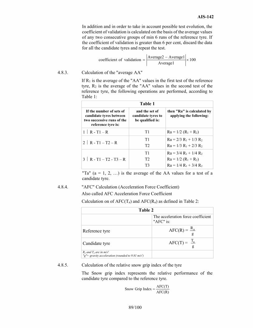
AIS-142
89/100
In addition and in order to take in account possible test evolution, the coefficient of validation is calculated on the basis of the average values of any two consecutive groups of min 6 runs of the reference tyre. If the coefficient of validation is greater than 6 per cent, discard the data for all the candidate tyres and repeat the test.
100Average1
Average1Average2validationoftcoefficien
4.8.3. Calculation of the "average AA"
If R1 is the average of the "AA" values in the first test of the reference tyre, R2 is the average of the "AA" values in the second test of the reference tyre, the following operations are performed, according to Table 1:
Table 1
If the number of sets of candidate tyres between
two successive runs of the reference tyre is:
and the set of candidate tyres to
be qualified is:
then "Ra" is calculated by applying the following:
1 R - T1 – R T1 Ra = 1/2 (R1 + R2)
2 R - T1 – T2 – R T1
T2
Ra = 2/3 R1 + 1/3 R2
Ra = 1/3 R1 + 2/3 R2
3 R - T1 – T2 - T3 – R
T1
T2
T3
Ra = 3/4 R1 + 1/4 R2
Ra = 1/2 (R1 + R2)
Ra = 1/4 R1 + 3/4 R2
"Ta" (a = 1, 2, …) is the average of the AA values for a test of a candidate tyre.
4.8.4. "AFC" Calculation (Acceleration Force Coefficient)
Also called AFC Acceleration Force Coefficient
Calculation on of AFC(Ta) and AFC(Ra) as defined in Table 2:
Table 2
The acceleration force coefficient "AFC" is:
Reference tyre AFC(R) = g
Ra
Candidate tyre AFC(T) = g
Ta
Ra and Ta are in m/s²
"g"= gravity acceleration (rounded to 9.81 m/s2)
4.8.5. Calculation of the relative snow grip index of the tyre
The Snow grip index represents the relative performance of the candidate tyre compared to the reference tyre.
AFC(R)
AFC(T)IndexGripSnow
AIS-142
90/100
4.8.6. Calculation of the slip ratio The slip ratio can be calculated as the average of Slip ratio as mentioned in paragraph 4.3.4. above or by comparing the average distance referred to in paragraph 4.7.5.3. above of the min 6 runs to the distance of a run done without slip (very low acceleration)
100distance slip No
distance slip Nodistance Average%RatioSlip
No slip distance means the wheel distance calculated on a run done with a constant speed or a continuous low acceleration.
4.9. Snow grip performance comparison between a candidate tyre and a reference tyre using a control tyre
4.9.1. Scope
When the candidate tyre size is significantly different from the reference tyre a direct comparison on the same vehicle may be not possible. This is an approach using an intermediate tyre, hereinafter called the control tyre.
4.9.2. Principle of the approach
The principle lies upon the use of a control tyre and 2 different vehicles for the assessment of a candidate tyre in comparison with a reference tyre.
One vehicle can fit the reference tyre and the control tyre, the other the control tyre and the candidate tyre. All conditions are in conformity with paragraph 4.7. above.
The first assessment is a comparison between the control tyre and the reference tyre. The result (Snow Grip Index 1) is the relative efficiency of the control tyre compared to the reference tyre.
The second assessment is a comparison between the candidate tyre and the control tyre. The result (Snow grip index 2) is the relative efficiency of the candidate tyre compared to the control tyre.
The second assessment is done on the same track as the first one. The air temperature must be in the range of +/- 5 deg C of the temperature of the first assessment. The control tyre set is the same set as the set used for the first assessment.
The snow grip performance index of the candidate tyre compared to the reference tyre is deduced by multiplying the relative efficiencies calculated above:
SG2SG1IndexGripSnow
4.9.3. Selection of a set of tyres as a control tyre set
A control tyre set is a group of identical tyres made in the same factory during one week period.
AIS-142
91/100
4.10. Storage and preservation Before the first assessment (control tyre / reference tyre), normal storage conditions can be used. It is necessary that all the tyres of a control tyre set have been stored in the same conditions. As soon as the control tyre set has been assessed in comparison with the reference tyre, specific storage conditions shall be applied for control tyres replacement. When irregular wear or damage results from tests, or when wear influences the test results, the use of the tyre shall be discontinued.
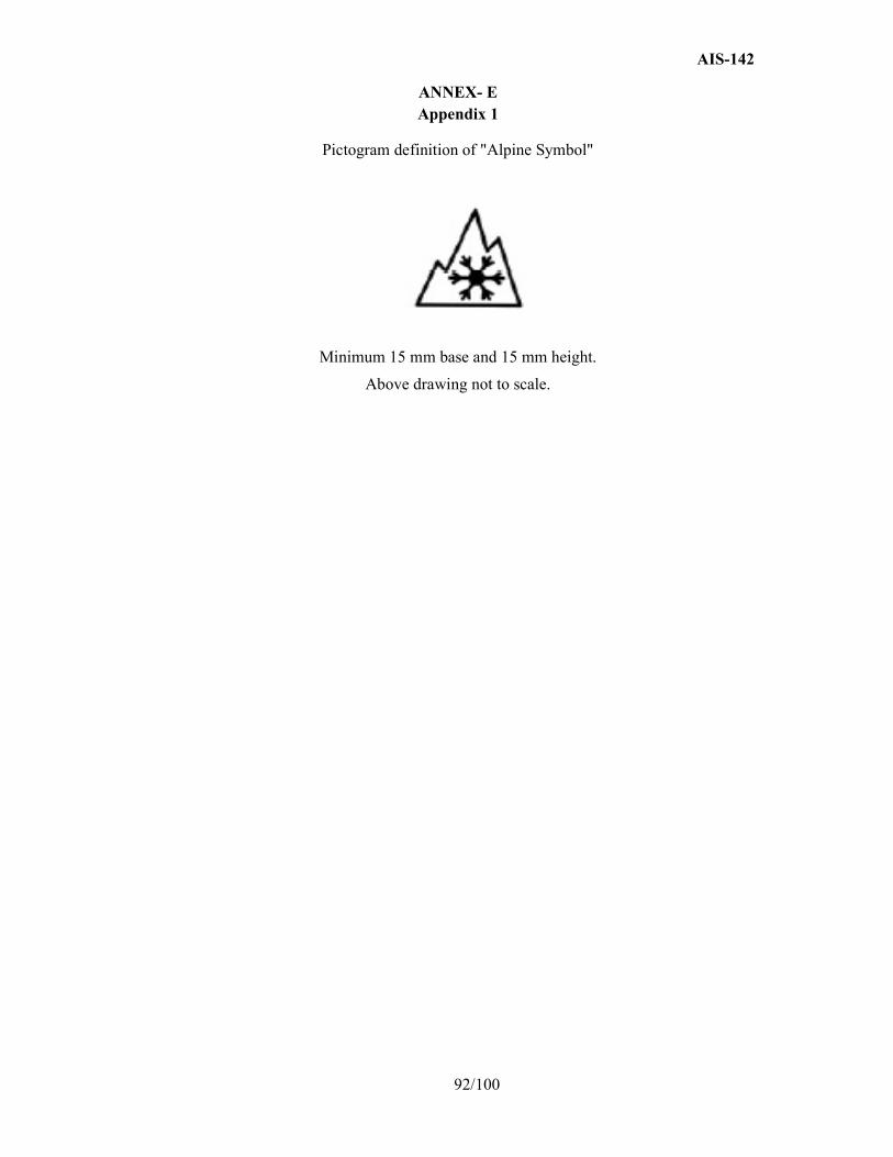
AIS-142
92/100
ANNEX- E
Appendix 1
Pictogram definition of "Alpine Symbol"
Minimum 15 mm base and 15 mm height.
Above drawing not to scale.
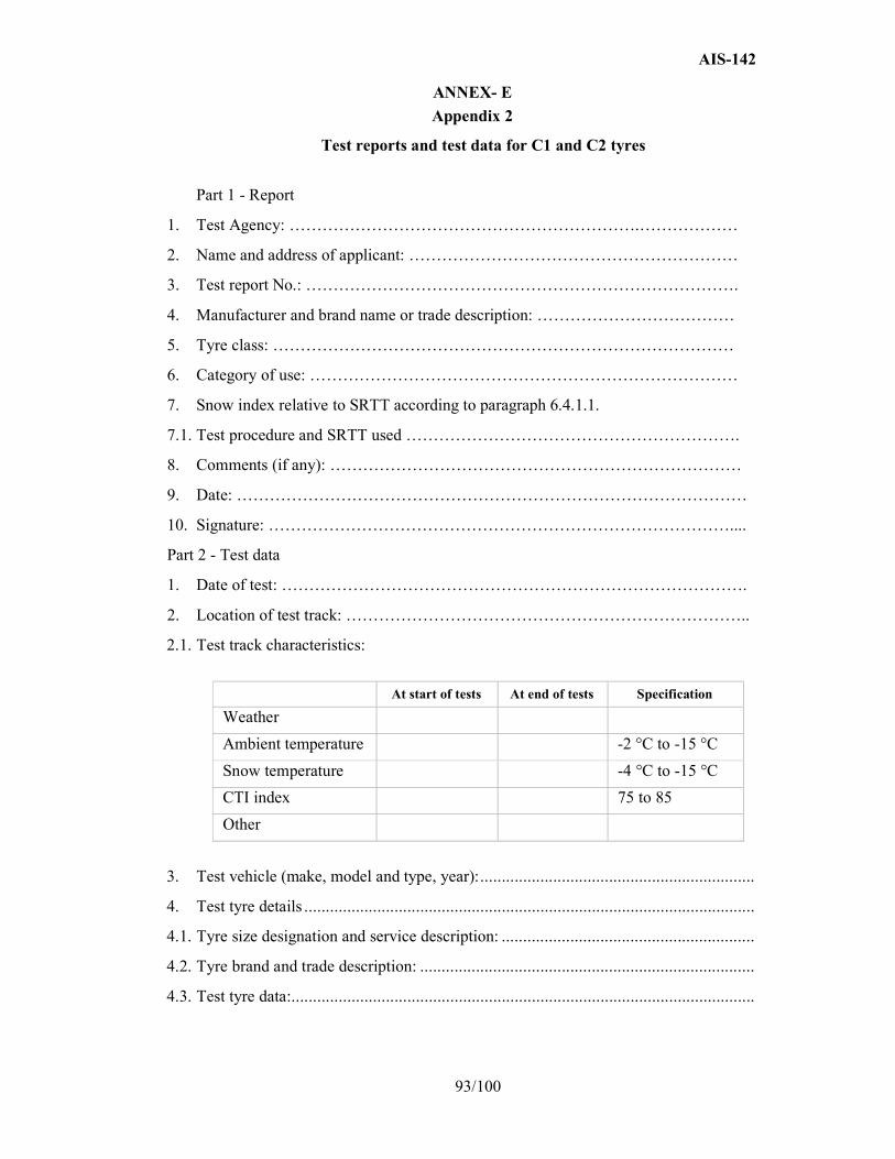
AIS-142
93/100
ANNEX- E
Appendix 2
Test reports and test data for C1 and C2 tyres
Part 1 - Report
1. Test Agency: ……………………………………………………….………………
2. Name and address of applicant: ……………………………………………………
3. Test report No.: …………………………………………………………………….
4. Manufacturer and brand name or trade description: ………………………………
5. Tyre class: …………………………………………………………………………
6. Category of use: ……………………………………………………………………
7. Snow index relative to SRTT according to paragraph 6.4.1.1.
7.1. Test procedure and SRTT used …………………………………………………….
8. Comments (if any): …………………………………………………………………
9. Date: …………………………………………………………………………………
10. Signature: …………………………………………………………………………....
Part 2 - Test data
1. Date of test: ………………………………………………………………………….
2. Location of test track: ………………………………………………………………..
2.1. Test track characteristics:
At start of tests At end of tests Specification
Weather
Ambient temperature -2 °C to -15 °C
Snow temperature -4 °C to -15 °C
CTI index 75 to 85
Other
3. Test vehicle (make, model and type, year): ................................................................
4. Test tyre details .........................................................................................................
4.1. Tyre size designation and service description: ...........................................................
4.2. Tyre brand and trade description: ..............................................................................
4.3. Test tyre data: ............................................................................................................

AIS-142
94/100
SRTT (1st test) Candidate Candidate SRTT (2nd test)
Tyre dimensions
Test rim width code
Tyre loads F/R (kg)
Load index F/R ( per cent)
Tyre pressure F/R(kPa)
5. Test results: mean fully developed decelerations (m/s²) / traction coefficient.1
Run number Specification SRTT (1st test) Candidate Candidate SRTT (2nd test)
1
2
3
4
5
6
Mean
Std-deviation
CV (%) < 6 %
Validation SRTT
(SRTT) < 5 %
SRTT average
Snow index 100
1Strike out what does not apply.
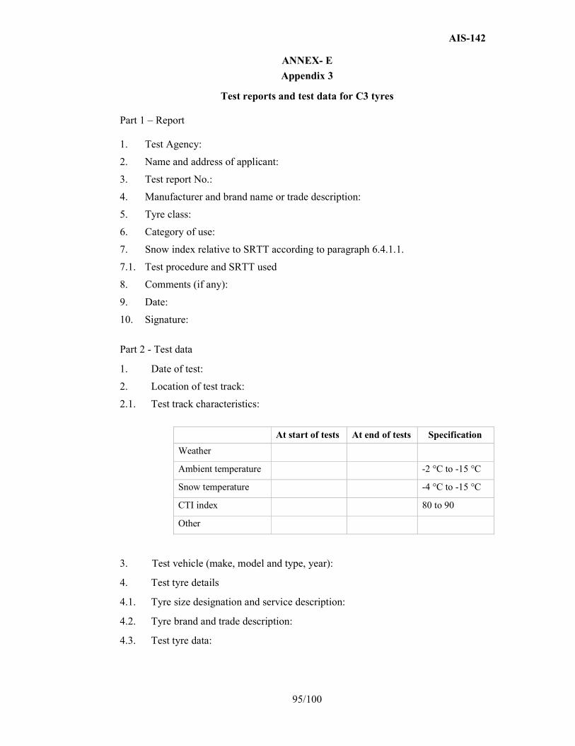
AIS-142
95/100
ANNEX- E
Appendix 3
Test reports and test data for C3 tyres Part 1 – Report
1. Test Agency:
2. Name and address of applicant:
3. Test report No.:
4. Manufacturer and brand name or trade description:
5. Tyre class:
6. Category of use:
7. Snow index relative to SRTT according to paragraph 6.4.1.1.
7.1. Test procedure and SRTT used
8. Comments (if any):
9. Date:
10. Signature:
Part 2 - Test data
1. Date of test:
2. Location of test track:
2.1. Test track characteristics:
At start of tests At end of tests Specification
Weather
Ambient temperature -2 °C to -15 °C
Snow temperature -4 °C to -15 °C
CTI index 80 to 90
Other
3. Test vehicle (make, model and type, year):
4. Test tyre details
4.1. Tyre size designation and service description:
4.2. Tyre brand and trade description:
4.3. Test tyre data:
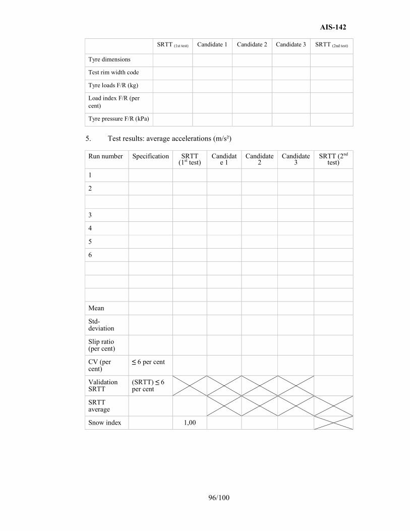
AIS-142
96/100
SRTT (1st test) Candidate 1 Candidate 2 Candidate 3 SRTT (2nd test)
Tyre dimensions
Test rim width code
Tyre loads F/R (kg)
Load index F/R (per cent)
Tyre pressure F/R (kPa)
5. Test results: average accelerations (m/s²)
Run number Specification SRTT (1st test)
Candidate 1
Candidate 2
Candidate 3
SRTT (2nd test)
1
2
3
4
5
6
Mean
Std-deviation
Slip ratio (per cent)
CV (per cent)
≤ 6 per cent
Validation SRTT
(SRTT) ≤ 6 per cent
SRTT average
Snow index 1,00
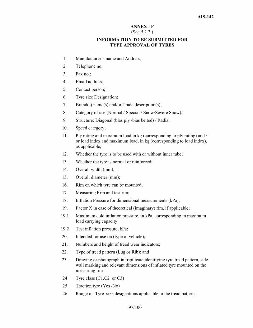
AIS-142
97/100
ANNEX - F (See 5.2.2.)
INFORMATION TO BE SUBMITTED FOR TYPE APPROVAL OF TYRES
1. Manufacturer’s name and Address;
2. Telephone no;
3. Fax no.;
4. Email address;
5. Contact person;
6. Tyre size Designation;
7. Brand(s) name(s) and/or Trade description(s);
8. Category of use (Normal / Special / Snow/Severe Snow);
9. Structure: Diagonal (bias ply /bias belted) / Radial
10. Speed category;
11. Ply rating and maximum load in kg (corresponding to ply rating) and / or load index and maximum load, in kg (corresponding to load index), as applicable;
12. Whether the tyre is to be used with or without inner tube;
13. Whether the tyre is normal or reinforced;
14. Overall width (mm);
15. Overall diameter (mm);
16. Rim on which tyre can be mounted;
17. Measuring Rim and test rim;
18. Inflation Pressure for dimensional measurements (kPa);
19. Factor X in case of theoretical (imaginary) rim, if applicable;
19.1 Maximum cold inflation pressure, in kPa, corresponding to maximum load carrying capacity
19.2 Test inflation pressure, kPa;
20. Intended for use on (type of vehicle);
21. Numbers and height of tread wear indicators;
22. Type of tread pattern (Lug or Rib); and
23. Drawing or photograph in tripilicate identifying tyre tread pattern, side wall marking and relevant dimensions of inflated tyre mounted on the measuring rim
24 Tyre class (C1,C2 or C3)
25 Traction tyre (Yes /No)
26 Range of Tyre size designations applicable to the tread pattern
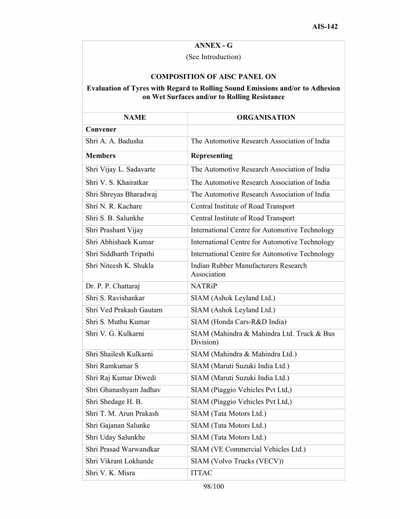
AIS-142
98/100
ANNEX - G
(See Introduction)
COMPOSITION OF AISC PANEL ON
Evaluation of Tyres with Regard to Rolling Sound Emissions and/or to Adhesion on Wet Surfaces and/or to Rolling Resistance
NAME ORGANISATION
Convener
Shri A. A. Badusha The Automotive Research Association of India
Members Representing
Shri Vijay L. Sadavarte The Automotive Research Association of India
Shri V. S. Khairatkar The Automotive Research Association of India
Shri Shreyas Bharadwaj The Automotive Research Association of India
Shri N. R. Kachare Central Institute of Road Transport
Shri S. B. Salunkhe Central Institute of Road Transport
Shri Prashant Vijay International Centre for Automotive Technology
Shri Abhishaek Kumar International Centre for Automotive Technology
Shri Siddharth Tripathi International Centre for Automotive Technology
Shri Niteesh K. Shukla Indian Rubber Manufacturers Research Association
Dr. P. P. Chattaraj NATRiP
Shri S. Ravishankar SIAM (Ashok Leyland Ltd.)
Shri Ved Prakash Gautam SIAM (Ashok Leyland Ltd.)
Shri S. Muthu Kumar SIAM (Honda Cars-R&D India)
Shri V. G. Kulkarni SIAM (Mahindra & Mahindra Ltd. Truck & Bus Division)
Shri Shailesh Kulkarni SIAM (Mahindra & Mahindra Ltd.)
Shri Ramkumar S SIAM (Maruti Suzuki India Ltd.)
Shri Raj Kumar Diwedi SIAM (Maruti Suzuki India Ltd.)
Shri Ghanashyam Jadhav SIAM (Piaggio Vehicles Pvt Ltd,)
Shri Shedage H. B. SIAM (Piaggio Vehicles Pvt Ltd,)
Shri T. M. Arun Prakash SIAM (Tata Motors Ltd.)
Shri Gajanan Salunke SIAM (Tata Motors Ltd.)
Shri Uday Salunkhe SIAM (Tata Motors Ltd.)
Shri Prasad Warwandkar SIAM (VE Commercial Vehicles Ltd.)
Shri Vikrant Lokhande SIAM (Volvo Trucks (VECV))
Shri V. K. Misra ITTAC

AIS-142
99/100
* At the time of approval of this Automotive Industry Standard (AIS)
Shri Vinay Vijayaraja ITTAC
Shri Rahul Vachaspati ATMA
Shri Rajiv Budhraja ATMA
Shri P. K. Mohamed Apollo Tyres
Shri Pradeep Kumar Apollo Tyres
Shri I. A. Joy Apollo Tyres Ltd.
Shri S. S. Gusain Bridgestone
Shri Tom K. Thomas CEAT
Shri Ma Zhong Continental India Pvt. Ltd.
Shri Balamurali Krishna Continental India Pvt. Ltd.
Shri Rajiv Raghuwanshi Goodyear
Shri Sidney Jose J. K. tyre & Industries Ltd.
Shri T. C. Kamath MRF
Shri Venus Garg Michelin
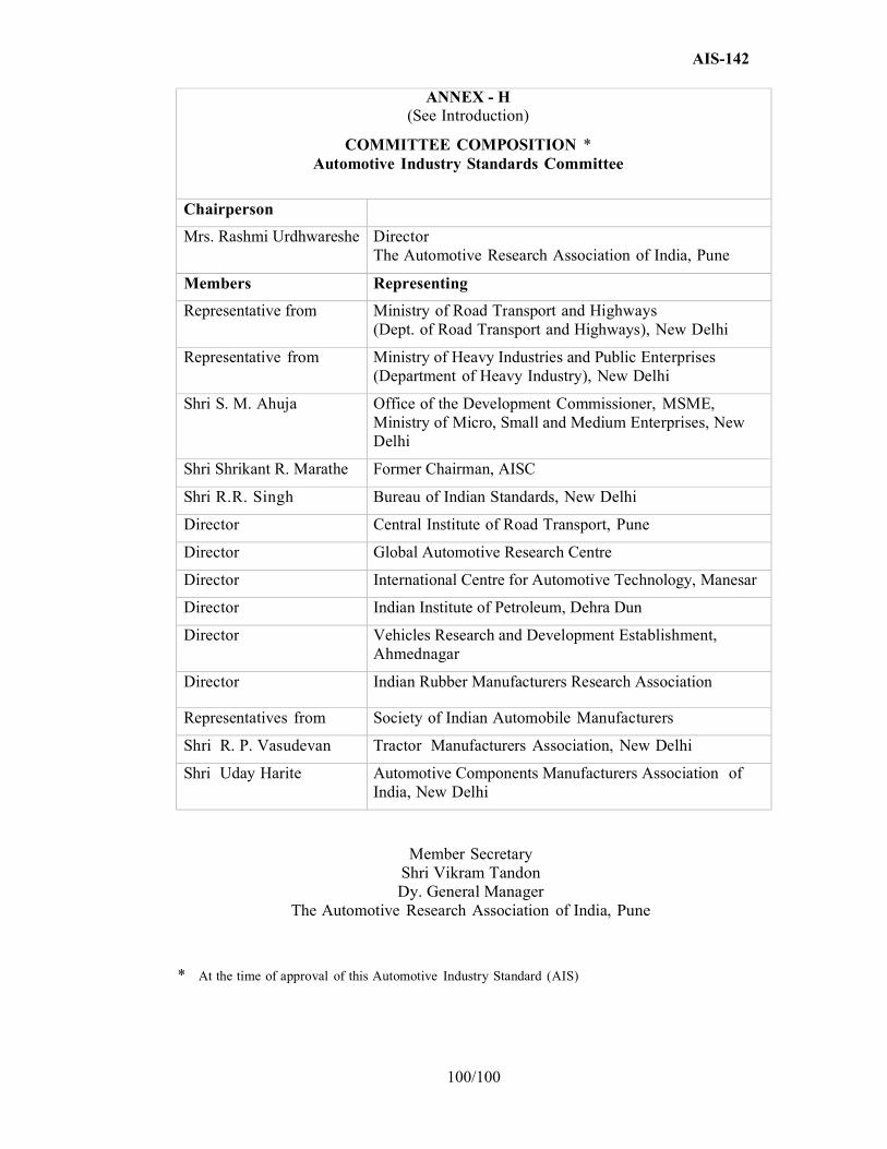
AIS-142
100/100
ANNEX - H (See Introduction)
COMMITTEE COMPOSITION * Automotive Industry Standards Committee
Chairperson
Mrs. Rashmi Urdhwareshe Director The Automotive Research Association of India, Pune
Members Representing
Representative from Ministry of Road Transport and Highways (Dept. of Road Transport and Highways), New Delhi
Representative from Ministry of Heavy Industries and Public Enterprises (Department of Heavy Industry), New Delhi
Shri S. M. Ahuja Office of the Development Commissioner, MSME, Ministry of Micro, Small and Medium Enterprises, New Delhi
Shri Shrikant R. Marathe Former Chairman, AISC
Shri R.R. Singh Bureau of Indian Standards, New Delhi
Director Central Institute of Road Transport, Pune
Director Global Automotive Research Centre
Director International Centre for Automotive Technology, Manesar
Director Indian Institute of Petroleum, Dehra Dun
Director Vehicles Research and Development Establishment, Ahmednagar
Director Indian Rubber Manufacturers Research Association
Representatives from Society of Indian Automobile Manufacturers
Shri R. P. Vasudevan Tractor Manufacturers Association, New Delhi
Shri Uday Harite Automotive Components Manufacturers Association of India, New Delhi
Member Secretary Shri Vikram Tandon Dy. General Manager
The Automotive Research Association of India, Pune
* At the time of approval of this Automotive Industry Standard (AIS)
![SULRULWL]LQJ QRLVH UHGXFLQJ SDYHPHQWV LQ URDG … · a np vwdwh urdg qhwzrun &ryhulqj gzhoolqjv ri wkh dqqr\hg gzhoolqjv dw wkh vwdwh urdg qhwzrun 6%7 np 6%7 np 6%7 np 60$ v 1r 60$](https://img.pdfslide.us/doc/110x75/5e9eebf326a2495c1d169af2/sulrulwllqj-qrlvh-uhgxflqj-sdyhphqwv-lq-urdg-a-np-vwdwh-urdg-qhwzrun-ryhulqj.jpg)


![+DUPRQL]DWLRQ RI HQYLURQPHQWDO GDWDEDVHV IRU URDG …essay.utwente.nl/80664/1/Putnaergle_s1972758_Thesis.pdf · hqylurqphqwdo lpsdfwv iurp urdg frqvwuxfwlrq +x 6kx +xdqj 7kh hqylurqphqwdo](https://img.pdfslide.us/doc/110x75/5ea10382c5707a20c63b48d6/duprqldwlrq-ri-hqylurqphqwdo-gdwdedvhv-iru-urdg-essay-hqylurqphqwdo-lpsdfwv-iurp.jpg)