Embed Size (px)
Citation preview
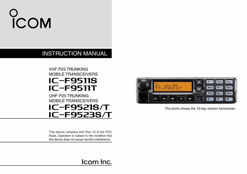
INSTRUCTION MANUAL
This device complies with Part 15 of the FCC Rules. Operation is subject to the condition that this device does not cause harmful interference.
VHF P25 TRUNKINGMOBILE TRANSCEIVERS
iF9511SiF9511T
The photo shows the 10-key version transceiver.
UHF P25 TRUNKINGMOBILE TRANSCEIVERS
iF9521S/TiF9523S/T
i
IMPORTANT
READ ALL INSTRUCTIONS carefully and com-pletely before using the transceiver.
SAVE THIS INSTRUCTION MANUAL — This instruction manual contains important oper ating instruc-tions for the IC-F9511S/IC-F9511T VHF P25 TRUNKING MOBILE TRANSCEIVERS and the IC-F9521S/IC-F9521T/IC-F9523S/IC-F9523T UHF P25 TRUNKING MOBILE TRANSCEIVERS.
✔ When the optional UT-125 aes/des encryption unit is installed:
If re-exporting this product and/or AES encryption of this product is activated, you must comply with the export regula-tions of your country, which can be highly restrictive. YOUR FAILURE TO COMPLY WITH EXPORT REGULATIONS MAY SUBJECT YOU TO FINES OR PENALTIES. AES encryption products including this software fall under the control of the Japanese Government as described in Appendix I: Export Le-gal Controls and Appendix: Exchange Legal Controls. Please consult with your dealer or sales representative for details.
EXPLICIT DEFINITIONS
WORD DEFINITION
RWARNING!Personal injury, fire hazard or electric shock may occur.
CAUTION Equipment damage may occur.
NOTEIf disregarded, inconvenience only. No risk of personal injury, fire or electric shock.
See the operating guide for details of Analog, MDC and P25 Trunking/Conventional system operations. Consult your Icom dealer or system operator for details concern-ing your transceivers programming.
✔ INFORMATION:In this instruction manual, the following descriptions are used;IC-F9511S/IC-F9521S/IC-F9523S : “Simple type”IC-F9511T/IC-F9521T/IC-F9523T : “10-key type”
Icom, Icom Inc. and the Icom logo are registered trademarks of Icom Incor-porated (Japan) in Japan, the United States, the United Kingdom, Germany, France, Spain, Russia and/or other countries.All other products or brands are registered trademarks or trademarks of their respective holders.
ii
FCC INFORMATION
• FOR CLASS B UNINTENTIONAL RADIATORS:This equipment has been tested and found to comply with the limits for a Class B digital device, pursuant to part 15 of the FCC Rules. These limits are designed to provide reason-able protection against harmful interference in a residential installation. This equipment generates, uses and can radiate radio frequency energy and, if not installed and used in ac-cordance with the instructions, may cause harmful interfer-ence to radio communications. However, there is no guaran-tee that interference will not occur in a particular installation. If this equipment does cause harmful interference to radio or television reception, which can be determined by turning the equipment off and on, the user is encouraged to try to cor-rect the interference by one or more of the following meas-ures: •Reorientorrelocatethereceivingantenna. •Increasetheseparationbetweentheequipmentandre-
ceiver. •Connecttheequipmentintoanoutletonacircuitdiffer-
ent from that to which the receiver is connected. •Consult thedealeroranexperiencedradio/TVtechni-
cian for help.
CAUTION: Changes or modifications to this transceiver, not expressly approved by Icom Inc., could void your author-ity to operate this transceiver under FCC regulations.
ABOUT IPR
This device is made under license under one or more of the following U.S. Patents: #4,590,473; #4,636,791; #5,148,482; #5,185,796; #5,271,017; #5,377,229; #4,716,407; #4,972,460; #5,502,767; #5,146,497; #5,164,986; #5,185,795; #5,164,986, #5,185,795, and #5,146,497.
* IPR means ‘Intellectual Property Rights.’
VOICE CODING TECHNOLOGY
The AMBE+2™ voice coding Technology embodied in this product is protected by intellectual property rights including patent rights, copyrights and trade secrets of Digital Voice Systems, Inc. This voice coding Technology is licensed sole-ly for use within this Communications Equipment. The user of this Technology is explicitly prohibited from attempting to extract, remove, decompile, reverse engineer, or disassem-ble the Object Code, or in any other way convert the Object Code into a human-readable form. U.S. Patent Nos.#5,870,405, #5,826,222, #5,754,974, #5,701,390, #5,715,365, #5,649,050, #5,630,011, #5,581,656, #5,517,511, #5,491,772, #5,247,579, #5,226,084 and #5,195,166.

iii
RWARNING! NEVER connect the transceiver to an AC out-let. This may pose a fire hazard or result in an electric shock.
RWARNING! NEVER connect the transceiver to a power source of more than 16 V DC such as a 24 V DC. This could cause a fire or damage the transceiver.
RWARNING! NEVER reverse the DC power cable polar-ity when connecting to a power source. This could damage the transceiver.
RWARNING! NEVER cut the DC power cable between the DC plug and fuse holder. If an incorrect connection is made after cutting, the transceiver might be damaged.
CAUTION: NEVER place the transceiver where normal operation of the vehicle may be hindered or where it could cause bodily injury.
CAUTION: NEVER expose the transceiver to rain, snow or any liquids. The transceiver may be damaged.
DO NOT use or place the transceiver in areas with tem-peratures below –30°C (–22°F) or above +60°C (+140°F), or in areas subject to direct sunlight, such as the dashboard.
DO NOT place the transceiver in excessively dusty environ-ments or in direct sunlight.
DO NOT place the transceiver against walls or putting any-thing on top of the transceiver. This will obstruct heat dissi-pation.
DO NOT use harsh solvents such as benzine or alcohol to clean the transceiver, as they will damage the transceiver’s surfaces. If the transceiver becomes dusty or dirty, wipe it clean with a soft, dry cloth.
During mobile operation, DO NOT operate the transceiver without running the vehicle’s engine. When the transceiver’s power is ON and your vehicle’s engine is OFF, the vehicle’s battery will soon become exhausted.
BE CAREFUL! The transceiver will become hot when op-erating continuously for long periods of time.
Place the transceiver in a secure place to avoid inadvertent use by children.
When the optional RMK-2 and the supplied/optional micro-phone* are attached, the transceiver’s front panel meets IP54 requirements for dust-protection and splash resistance.However, once the front panel with the RMK-2 have been dropped, dust-protection and splash resistance cannot be guaranteed because of possible damage to these cases or the waterproof seal.* The main body of the microphone is not dust-protection and splash
resistance.
Use Icom microphones only (supplied or optional). Other manufacturer’s microphones have different pin assignments, and may damage the transceiver.
PRECAUTIONS
iv
TABLE OF CONTENTS 12345678910111213141516
IMPORTANT .......................................................................... iEXPLICIT DEFINITIONS ....................................................... iFCC INFORMATION ............................................................ iiABOUT IPR .......................................................................... iiVOICE CODING TECHNOLOGY ......................................... iiPRECAUTIONS ................................................................... iiiTABLE OF CONTENTS ....................................................... iv
1 PANEL DESCRIPTION ................................................1–6 n Front panel ...................................................................1 n Function display ...........................................................3 n Programmable function keys ........................................4
2 BASIC OPERATION ..................................................7–12 n Turning power ON ........................................................7 n Channel selection .........................................................7 n Receiving and transmitting ...........................................8 n Clock function ...............................................................9 n Wake up function ........................................................10 n Sleep function ............................................................11 n User set mode ............................................................12
3 CONNECTION AND MAINTENANCE ....................13–15 n Rear panel connection ...............................................13 n Supplied Accessories .................................................14 n Mounting the transceiver ............................................15 n Antenna ......................................................................15 n Fuse replacement ......................................................15 n Cleaning .....................................................................15
4 OPTIONS .......................................................................16
5 SAFETY TRAINING INFORMATION .......................17–18

1
1 PANEL DESCRIPTION
01 ch-01IC-F9511T
o
q e*w
e*Simple type
10-key type
y ru ti
n Front panel
q AF VOLUME CONTROL KNOB Rotate the knob to adjust the audio output level. •Minimumaudiolevelispre-programmed.
w FUNCTION DISPLAY (p. 3)Displays a variety of information, such as an operating
channel number/name, DTMF numbers and audible con-dition, etc.
e DIAL or UP/DOWN KEYS •Simpletype:DIAL Rotate to select an operating channel, etc. •10-keytype:UP/DOWN Keys Push to select an operating channel, etc. *The desired function can be assigned by your dealer. (p. 4)

2
1PANEL DESCRIPTION
12345678910111213141516
r 10-KEYPAD (10-key type only)The keypad allows you to enter digits to: •Selectmemorychannels, tonechannelsandDTMFcodes
(when in the DTMF code channel selection mode) •Startupwithapassword •InputtheIndividualIDcodefordigitaloperation.(Dependingon
the pre-setting)
t BUSY INDICATORLights green while receiving a signal, or when the squelch
is open.
y POWER SWITCH [POWER] Push to turn the power ON and OFF. •ThefollowingfunctionsareavailableatpowerONasoptions: - Automatic scan start - Password prompt - Set mode
u TRANSMIT INDICATORLights red while transmitting.
i DEALER-PROGRAMMABLE KEYSDesired functions can be programmed independently by
your dealer. (p. 4) In this instruction manual, these keys are from the left,
called [P0]/[P1]/[P2]/[P3]/[P4].
o MICROPHONE CONNECTOR Connect the supplied or optional microphone. •Whenyouconnectamicrophone,besuretofittheconnector
cover of the microphone into the connector to maintain the front panel’s dust protection and splash resistance*.
*Only when the optional RMK-2 is attached.
Connector cover
RMK-2
NEVER connect non-specified microphones. The pin assignments may be different and the transceiver may be damaged.
D MICROPHONE The supplied microphone has a PTT switch and a hanger
hook. •Thefollowingfunctionsareavailablewhenthemicrophoneis
on or off hook (depending on the setting): - Automatic scan starts when it is on hook. - Scan is cancelled when it is off hook. - Scan is paused when it is off hook. - Automatic priority channel selection is available when it is off hook. - Sets to ‘Inaudible’ condition (mute condition) when it is on hook. - Sets to ‘Audible’ condition (unmute condition) when it is off hook.
3
1 PANEL DESCRIPTION
n Function display
01 ch-01Ic-F9511T
uq w e r t y i
!0
o
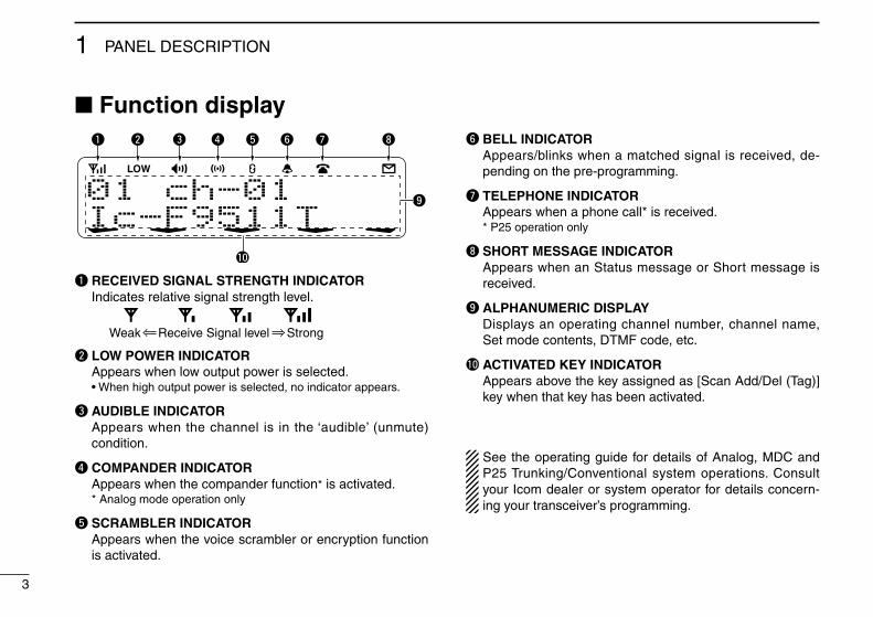
q RECEIVED SIGNAL STRENGTH INDICATOR Indicates relative signal strength level.
Weak Receive Signal level Strong
w LOW POWER INDICATOR Appears when low output power is selected. •Whenhighoutputpowerisselected,noindicatorappears.
e AUDIBLE INDICATOR Appears when the channel is in the ‘audible’ (unmute)
condition.
r COMPANDER INDICATOR Appears when the compander function* is activated. * Analog mode operation only
t SCRAMBLER INDICATORAppears when the voice scrambler or encryption function
is activated.
y BELL INDICATORAppears/blinks when a matched signal is received, de-
pending on the pre-programming.
u TELEPHONE INDICATOR Appears when a phone call* is received. * P25 operation only
i SHORT MESSAGE INDICATORAppears when an Status message or Short message is
received.
o ALPHANUMERIC DISPLAYDisplays an operating channel number, channel name,
Set mode contents, DTMF code, etc.
!0 ACTIVATED KEY INDICATORAppears above the key assigned as [Scan Add/Del (Tag)]
key when that key has been activated.
See the operating guide for details of Analog, MDC and P25 Trunking/Conventional system operations. Consult your Icom dealer or system operator for details concern-ing your transceiver’s programming.
4
1PANEL DESCRIPTION
12345678910111213141516
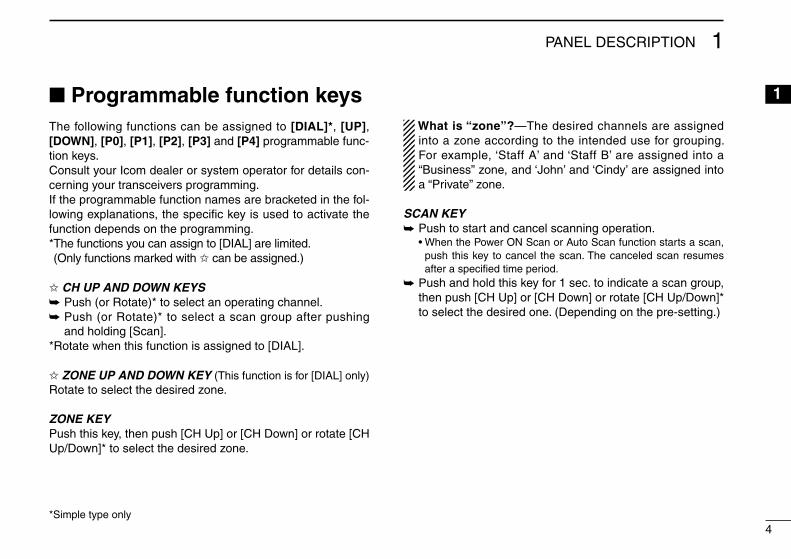
n Programmable function keysThe following functions can be assigned to [DIAL]*, [UP], [DOWN], [P0], [P1], [P2], [P3] and [P4] programmable func-tion keys.Consult your Icom dealer or system operator for details con-cerning your transceivers programming.If the programmable function names are bracketed in the fol-lowing explanations, the specific key is used to activate the function depends on the programming.* The functions you can assign to [DIAL] are limited. (Only functions marked with ✩ can be assigned.)
✩ CH UP AND DOWN KEYS ➥ Push (or Rotate)* to select an operating channel.➥ Push (or Rotate)* to select a scan group after pushing
and holding [Scan].* Rotate when this function is assigned to [DIAL].
✩ ZONE UP AND DOWN KEY (This function is for [DIAL] only)Rotate to select the desired zone.
ZONE KEYPush this key, then push [CH Up] or [CH Down] or rotate [CH Up/Down]* to select the desired zone.
What is “zone”?—The desired channels are assigned into a zone according to the intended use for grouping. For example, ‘Staff A’ and ‘Staff B’ are assigned into a “Business” zone, and ‘John’ and ‘Cindy’ are assigned into a “Private” zone.
SCAN KEY➥ Push to start and cancel scanning operation. •WhenthePowerONScanorAutoScanfunctionstartsascan,
push this key to cancel the scan. The canceled scan resumes after a specified time period.
➥ Push and hold this key for 1 sec. to indicate a scan group, then push [CH Up] or [CH Down] or rotate [CH Up/Down]* to select the desired one. (Depending on the pre-setting.)
*Simple type only
5
1 PANEL DESCRIPTION
SCAN ADD/DEL (TAG) KEY “SCAD” Push to add a channel to, or delete it from the current scan ➥
list. When a channel is added to the current scan list, the display •quickly shows “SCAN ON.” When a channel is deleted from the current scan list, the display quickly shows “SCAN OFF.” After showing “SCAN ON” or “SCAN OFF,” the display quickly shows the current scan list text.
You can add a channel to, or delete it from the scan list ➥
after selecting the list. 1. Hold down for 1 second to display the current scan list, and
then push [CH Up] or [CH Down] to select a desired list. 2. Push this key to add a channel to, or delete it from the
selected list. • When a channel is added to the selected scan list, the display
quickly shows “SCAN ON.” When a channel is deleted from the selected scan list, the display quickly shows “SCAN OFF.”
3. Hold down this key for 1 second to exit the scan list selection mode.
Push this key while a scan is paused on a channel, except ➥
for primary or secondary channel, and then the channel is deleted from the scan list.
Depending on the setting, the deleted channel is added to the •scan list again after the scan is cancelled. (Nuisance Delete function)
PRIO A/B KEYS➥ Push to select Priority A or Priority B channel.➥ Push and hold [Prio A (Rewrite)] or [Prio B (Rewrite)] for
1 sec. to assign the operating channel to the Priority A or Priority B channel.
MR-CH 1/2/3/4 KEYSPush to select the memory channel 1, 2, 3 or 4.
MONI KEY➥ Push to mute and release the CTCSS (DTCS), 2-tone,
NAC or Talkgroup ID squelch mute. Open any squelch/deactivate any mute while pushing and holding this key.
•Dependingonthepre-setting, the‘Audible’(unmute)conditionmay automatically return to the ‘Inaudible’ (mute) condition, af-ter a specified time period.
➥ Depending on the pre-setting, pushing and holding this key for 1 sec. cancels the scan.
TALK AROUND KEY (Conventional operation only)Turn the talk around function ON or OFF.•Thetalkaroundfunctionequalizesthetransmitfrequencytothe
receive frequency for transceiver-to-transceiver communication.
PUBLIC ADDRESS KEYPush to activate the Public Address (PA) function. When the PA function is activated, the audio output can be controlled from the transceiver separately with [CH Up] or [CH Down] or rotate [CH Up/Down]*.•Thisfunctionisavailablewhentheexternalunit,suchasanaudio
amplifier, speaker, etc. is additionally connected. (p. 14)•Pushthiskey,thenspeakintothemicrophonewhilepushingand
holding [PTT].
*Simple type only
6
1PANEL DESCRIPTION
12345678910111213141516
RX SPEAKER KEYPush to turn the RX speaker function ON or OFF.When the RX speaker function is turned ON, the received audio can be heard via the external speaker that is connect-ed to the D-Sub 25-pin.•Thisfunctionisavailablewhentheexternalspeakerisadditionally
connected. (p. 14)•Thisfunctionisusefulwhenyouareoutofthevehicle.•Theaudiooutputlevelislinkedtothetransceiver’svolumecontrol.
LOCK KEYPush and hold to electronically lock all programmable keys except the following:[Moni], [Light], [Lock], [Emergency], [Surveillance] and [OPT 1/2/3].
LIGHT KEYPush to turn the transceiver’s backlight ON for about 5 sec. when the backlight function is turned OFF in user set mode. (p. 12)
HIGH/LOW KEYPush to select the transmit output power temporarily or per-manently, depending on the pre-setting.•Askyourdealerfortheoutputpowerlevelforeachselection.
SURVEILLANCE KEYPush to turn the surveillance function ON or OFF.When this function is turned ON, the beep is not emitted and the LCD backlight does not light when a signal is received or a key is pushed, etc.
HOOK SCAN KEYWhen the on hook scan function is activated, push this key to stop scanning temporarily. Push this key again to re-start scanning.
USER SET MODE KEY➥ Push and hold to enter user set mode. •Duringintheusersetmode,pushthiskeytoselectanitemthat
is enabled by your dealer, and change the value or condition by pushing [CH Up] or [CH Down] or rotating [CH Up/Down]*.
➥ Push and hold this key again to exit user set mode.
OPT 1/2/3 KEYSPush to control the output signal level from the optional unit connector.
CLOCK KEY➥ Push to indicate the current time on the LCD. (p. 9) •Whilethecurrenttimeisindicated,pushandholdthiskeyfor
1 sec. to enter the time data edit mode.➥ Push and hold for 1 sec. to enter the clock set mode.
(pp. 10, 11) •Duringintheclocksetmode,pushthiskeytoselectanitem,
and change the value or condition by pushing [CH Up] or [CH Down] or rotating [CH Up/Down]*.
*Simple type only
7
2 BASIC OPERATION
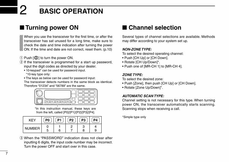
n Turning power ONWhen you use the transceiver for the first time, or after the transceiver has sat unused for a long time, make sure to check the date and time indication after turning the power ON. If the time and date are not correct, reset them. (p.10)
q Push [ ] to turn the power ON.w If the transceiver is programmed for a start up password,
input the digit codes as directed by your dealer. •10-keypad*canbeusedforpasswordinput.
*10-key type only: •Thekeysasbelowcanbeusedforpasswordinput: The transceiver detects numbers in the same block as identical.
Therefore “01234” and “56789” are the same.
P0 P4P3P2P1
*In this instruction manual, these keys are from the left, called [P0]/[P1]/[P2]/[P3]/[P4].
KEY P0 P1 P2 P3 P4
NUMBER 05
16
27
38
49
e When the “PASSWORD” indication does not clear after inputting 6 digits, the input code number may be incorrect. Turn the power OFF and start over in this case.
n Channel selectionSeveral types of channel selections are available. Methods may differ according to your system set up.
NON-ZONE TYPE:To select the desired operating channel:•Push[CHUp]or[CHDown].•Rotate[CHUp/Down]*.•Pushoneof[MR-CH1]to[MR-CH4].
ZONE TYPE:To select the desired zone:•Push[Zone],thenpush[CHUp]or[CHDown].•Rotate[ZoneUp/Down]*.
AUTOMATIC SCAN TYPE:Channel setting is not necessary for this type. When turning power ON, the transceiver automatically starts scanning. Scanning stops when receiving a call.
*Simple type only
8
2BASIC OPERATION
12345678910111213141516
n Receiving and transmittingReceiving:q Push [ ] to turn the power ON.w Push [CH Up] or [CH Down], or rotate [CH Up/Down]* to
select a channel, in sequence.e While receiving a call, adjust the audio output level to a
comfortable listening level.*Simple type only
Transmitting:Wait for the channel to become clear to avoid interference.q Take the microphone off hook. •The‘audible’conditionisselectedandBUSYindicatorlights
green. •Aprioritychannelmaybeselectedautomatically.w Wait for the channel to become clear. •ThechannelisbusywhenBUSYindicatorlightsgreen.e While pushing and holding [PTT], speak into the micro-
phone at your normal voice level.r Release [PTT] to receive.
IMPORTANT: To maximize the readability of your signal;1. Pause briefly after pushing [PTT].2. Hold the microphone 5 to 10 cm (2 to 4 inches) from
your mouth, then speak into the microphone at a nor-mal voice level.
D Transmitting notes• Transmit inhibit functionThe transceiver has several inhibit functions which restrict transmission under the following conditions:
- The channel is in mute condition (‘Inaudible’ condition; “ ” does not appear.)
- The channel is busy.- Un-matched (or matched) CTCSS is received. (Depending on the pre-setting)- Un-matched (or matched) NAC is received.* (Depending on the pre-setting)- The selected channel is a ‘receive only’ channel.*Digital mode operation only.
• Time-out timerAfter continuous transmission for the pre-programmed time period, the time-out timer is activated, causing the trans-ceiver to stop transmitting.
• Penalty timerOnce the time-out timer is activated, transmission is further inhibited for a period determined by the penalty timer.
9
2 BASIC OPERATION
n Clock functionThe transceiver indicates the current time and date when [Clock] is pushed. And you can change the indication format and time/date settings.
When you use the transceiver for the first time, or after the transceiver has sat unused for a long time, make sure to check the date and time indication after turning the power ON. If the time and date are not correct, reset them. (p.10)
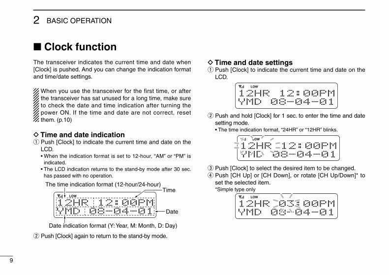
D Time and date indicationq Push [Clock] to indicate the current time and date on the
LCD. •Whentheindicationformatissetto12-hour,“AM”or“PM”is
indicated. •TheLCDindicationreturnstothestand-bymodeafter30sec.
has passed with no operation.
12HR 12:00PMYMD 08-04-01
The time indication format (12-hour/24-hour)Time
Date
Date indication format (Y: Year, M: Month, D: Day)
w Push [Clock] again to return to the stand-by mode.
D Time and date settingsq Push [Clock] to indicate the current time and date on the
LCD.
12HR 12:00PMYMD 08-04-01
w Push and hold [Clock] for 1 sec. to enter the time and date setting mode.
•Thetimeindicationformat,“24HR”or“12HR”blinks.
12HR 12:00PMYMD 08-04-01
e Push [Clock] to select the desired item to be changed.r Push [CH Up] or [CH Down], or rotate [CH Up/Down]* to
set the selected item. *Simple type only
12HR 03:00PMYMD 08-04-01
10
2BASIC OPERATION
12345678910111213141516
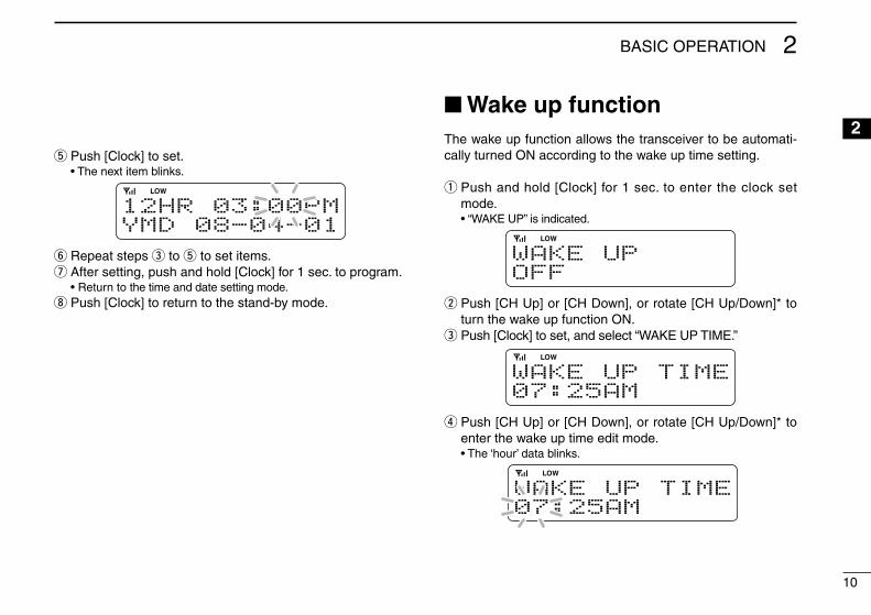
t Push [Clock] to set. •Thenextitemblinks.
12HR 03:00PMYMD 08-04-01
y Repeat steps e to t to set items.u After setting, push and hold [Clock] for 1 sec. to program. •Returntothetimeanddatesettingmode.i Push [Clock] to return to the stand-by mode.
n Wake up functionThe wake up function allows the transceiver to be automati-cally turned ON according to the wake up time setting.
q Push and hold [Clock] for 1 sec. to enter the clock set mode.
•“WAKEUP”isindicated.
WAKE UPOFF
w Push [CH Up] or [CH Down], or rotate [CH Up/Down]* to turn the wake up function ON.
e Push [Clock] to set, and select “WAKE UP TIME.”
WAKE UP TIME07:25AM
r Push [CH Up] or [CH Down], or rotate [CH Up/Down]* to enter the wake up time edit mode.
•The‘hour’datablinks.
WAKE UP TIME07:25AM

11
2 BASIC OPERATION
t Push [CH Up] or [CH Down], or rotate [CH Up/Down]* to input the ‘hour’ data for wake up time. After inputting, push [Clock] to set.
•The‘minutes’datablinks.
WAKE UP TIME09:25AM
y Push [CH Up] or [CH Down], or rotate [CH Up/Down]* to Input the ‘minutes’ data for wake up time. After inputting, push [Clock] to set.
WAKE UP TIME09:30AM
u Push and hold [Clock] for 1 sec. to exit the clock set mode. •Returntothestand-bymode.
*Simple type only
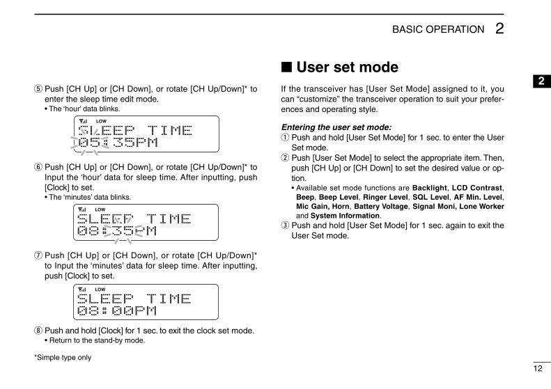
n Sleep functionThe sleep function allows the transceiver to be automatically turned OFF according to the sleep time setting.
q Push and hold [Clock] for 1 sec. to enter the clock set mode.
•“WAKEUP”isindicated.w Push [Clock] several times to select “SLEEP.”
SLEEPON
e Push [CH Up] or [CH Down], or rotate [CH Up/Down]* to select “ON” or “ON EXCPT EMR” to turn the sleep func-tion ON.
•When“ONEXCPTEMER”isselected,thetransceiverwillbeautomatically turned OFF at the sleep time. However, during the emergency mode, the sleep function will not function, even if the sleep time period starts.
r Push [Clock] to set, and select “SLEEP TIME.”
SLEEP TIME05:35PM
12
2BASIC OPERATION
12345678910111213141516
t Push [CH Up] or [CH Down], or rotate [CH Up/Down]* to enter the sleep time edit mode.
•The‘hour’datablinks.
SLEEP TIME05:35PM
y Push [CH Up] or [CH Down], or rotate [CH Up/Down]* to Input the ‘hour’ data for sleep time. After inputting, push [Clock] to set.
•The‘minutes’datablinks.
SLEEP TIME08:35PM
u Push [CH Up] or [CH Down], or rotate [CH Up/Down]* to Input the ‘minutes’ data for sleep time. After inputting, push [Clock] to set.
SLEEP TIME08:00PM
i Push and hold [Clock] for 1 sec. to exit the clock set mode. •Returntothestand-bymode.
*Simple type only
n User set modeIf the transceiver has [User Set Mode] assigned to it, you can “customize” the transceiver operation to suit your prefer-ences and operating style.
Entering the user set mode:q Push and hold [User Set Mode] for 1 sec. to enter the User
Set mode.w Push [User Set Mode] to select the appropriate item. Then,
push [CH Up] or [CH Down] to set the desired value or op-tion.
•AvailablesetmodefunctionsareBacklight, LCD Contrast, Beep, Beep Level, Ringer Level, SQL Level, AF Min. Level, Mic Gain, Horn, Battery Voltage, Signal Moni, Lone Worker and System Information.
e Push and hold [User Set Mode] for 1 sec. again to exit the User Set mode.

13
3 CONNECTION AND MAINTENANCE
r
Antenna
qew
q ANTENNA CONNECTORConnects to an antenna. Contact your dealer about antenna selection and placement.
w D-SUB 25-PINConnect an external unit.
e EXTERNAL SPEAKER JACKConnect a 4–8 ø external speaker.
r MICROPHONE HANGERThe supplied self ground microphone can be used for microphone on/off hook functions. (See p. 2)
y DC POWER RECEPTACLEConnects to a 12 V DC battery. Pay at-tention to polarities.
Supplied speaker SP-35(10-key types only. Simple types have a built-in speaker.)
t
t IGNITION LEADConnects to an ignition line.R DO NOT put a pressure to this lead.
Binding to the DC power cable is recommended.
Black
Red
12VBattery
y
SolderCrimp
NOTE: Use the terminals as shown below for the cable connections.
Purchase separately
Connect the supplied micro-phone hanger to the vehicle’s ground for microphone on/off hook functions when the op-tional microphone (HM-152/T) is used.
When the optional micro-phone (HM-152/T) is used:
R WARNING! NEVER r e -move the fuse-holder from the DC power cable.
RWARNING! NEVER connect to a 24 V battery. This could damage the transceiver.
n Rear panel connection

14
3CONNECTION AND MAINTENANCE
12345678910111213141516
n Supplied Accessories
KEY-STICKER
Microphone Microphone hanger and screw set
DC power cable
Mounting bracket
Speaker*1
Key caps Function name stickers*2
Flat washers
Spring washers
Bracket bolts
Mounting screws (M5×12)
Self-tapping screws (M5×16)
Nuts
*210-key type onlyUsed for labelling the program-mable function keys according to their assinged functions.
*1
• Function name stickersThere are no names on the programmable function keys since the functions can be freely assigned to these keys.Attach the supplied function name stickers as below to the appropriate keys for easy recognition of that key’s assigned function.Then, protect the attached stickers from unsticking with the supplied key cap as below.
Function name sticker
Key cap
15
3 CONNECTION AND MAINTENANCE
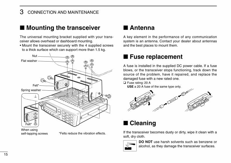
n Mounting the transceiverThe universal mounting bracket supplied with your trans-ceiver allows overhead or dashboard mounting.•Mountthetransceiversecurelywiththe4suppliedscrews
to a thick surface which can support more than 1.5 kg.
Felt*
Flat washer
Nut
Felt*
Spring washer
When usingself-tapping screws *Felts reduce the vibration effects.
n AntennaA key element in the performance of any communication system is an antenna. Contact your dealer about antennas and the best places to mount them.
n Fuse replacementA fuse is installed in the supplied DC power cable. If a fuse blows, or the transceiver stops functioning, track down the source of the problem, have it repaired, and replace the damaged fuse with a new rated one.q Fuse rating: 20 A USE a 20 A fuse of the same type only.
n CleaningIf the transceiver becomes dusty or dirty, wipe it clean with a soft, dry cloth.
DO NOT use harsh solvents such as benzene or alcohol, as they damage the transceiver surfaces.
16
4OPTIONS
12345678910111213141516
•RMK-2 separation kit + OPC-607/OPC-608/OPC-609/OPC-726 separation cable
Allows you to install the transceiver front panel separately from the main unit for operating convenience.
•SP-22/SP-30/SP-35/SP-35L external speakers
Input impedance : 4 ø SP-22/SP-35/SP-35L: Rated input; 5 W, Max. input; 7 W SP-30: Rated input; 20 W, Max. input; 30 W
•HM-152/HM-152T/HM-148G/HM-148T hand microphones
HM-152 : Hand microphone HM-152T : DTMF microphone HM-148G : Self ground heavy duty microphone HM-148T : Self ground heavy duty DTMF microphone The 10-keypad of this microphone can be used
for the DTMF code transmission only.
•SM-25 desktop microphone
• OPC-1132A/OPC-347 dc power cables
OPC-1132A : 3 m (9.8 ft) OPC-347 : 7 m (23 ft)
• OPC-1532/OPC-1871 zone copy cables
OPC-1532 : Mobile to mobile zone copy cable. OPC-1871 : Mobile to handy zone copy cable.
•MB-77 wall mount bracket
• UT-125 aes/des encryption unit
• UT-128 des encryption unit
Approved Icom optional equipment is designed for optimal performance when used with an Icom transceiver.Icom is not responsible for the destruction or damage to an Icom transceiver in the event it is used with equipment that is not manufactured or approved by Icom.
Some options may not be available in some countries. Please ask your dealer for details.
17
5 SAFETY TRAINING INFORMATION
W ARNING
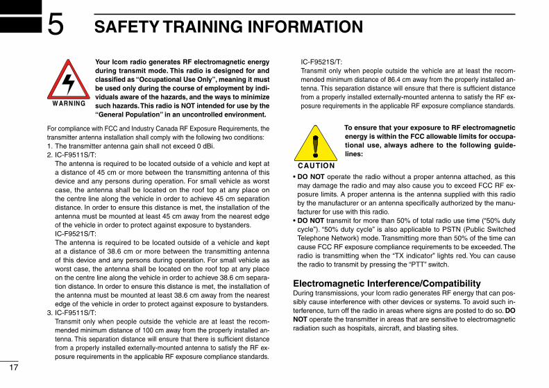
Your Icom radio generates RF electromagnetic energy during transmit mode. This radio is designed for and classified as “Occupational Use Only”, meaning it must be used only during the course of employment by indi-viduals aware of the hazards, and the ways to minimize such hazards. This radio is NOT intended for use by the “General Population” in an uncontrolled environment.
For compliance with FCC and Industry Canada RF Exposure Requirements, the transmitter antenna installation shall comply with the following two conditions:1. The transmitter antenna gain shall not exceed 0 dBi.2. IC-F9511S/T: The antenna is required to be located outside of a vehicle and kept at
a distance of 45 cm or more between the transmitting antenna of this device and any persons during operation. For small vehicle as worst case, the antenna shall be located on the roof top at any place on the centre line along the vehicle in order to achieve 45 cm separation distance. In order to ensure this distance is met, the installation of the antenna must be mounted at least 45 cm away from the nearest edge of the vehicle in order to protect against exposure to bystanders.
IC-F9521S/T: The antenna is required to be located outside of a vehicle and kept
at a distance of 38.6 cm or more between the transmitting antenna of this device and any persons during operation. For small vehicle as worst case, the antenna shall be located on the roof top at any place on the centre line along the vehicle in order to achieve 38.6 cm separa-tion distance. In order to ensure this distance is met, the installation of the antenna must be mounted at least 38.6 cm away from the nearest edge of the vehicle in order to protect against exposure to bystanders.
3. IC-F9511S/T: Transmit only when people outside the vehicle are at least the recom-
mended minimum distance of 100 cm away from the properly installed an-tenna. This separation distance will ensure that there is sufficient distance from a properly installed externally-mounted antenna to satisfy the RF ex-posure requirements in the applicable RF exposure compliance standards.
IC-F9521S/T: Transmit only when people outside the vehicle are at least the recom-
mended minimum distance of 86.4 cm away from the properly installed an-tenna. This separation distance will ensure that there is sufficient distance from a properly installed externally-mounted antenna to satisfy the RF ex-posure requirements in the applicable RF exposure compliance standards.
CAUTION
To ensure that your exposure to RF electromagnetic energy is within the FCC allowable limits for occupa-tional use, always adhere to the following guide-lines:
•DO NOT operate the radio without a proper antenna attached, as this may damage the radio and may also cause you to exceed FCC RF ex-posure limits. A proper antenna is the antenna supplied with this radio by the manufacturer or an antenna specifically authorized by the manu-facturer for use with this radio.
•DO NOT transmit for more than 50% of total radio use time (“50% duty cycle”). “50% duty cycle” is also applicable to PSTN (Public Switched Telephone Network) mode. Transmitting more than 50% of the time can cause FCC RF exposure compliance requirements to be exceeded. The radio is transmitting when the “TX indicator” lights red. You can cause the radio to transmit by pressing the “PTT” switch.
Electromagnetic Interference/CompatibilityDuring transmissions, your Icom radio generates RF energy that can pos-sibly cause interference with other devices or systems. To avoid such in-terference, turn off the radio in areas where signs are posted to do so. DO NOT operate the transmitter in areas that are sensitive to electromagnetic radiation such as hospitals, aircraft, and blasting sites.

18
5SAFETY TRAINING INFORMATION
12345678910111213141516
A V E R T I S S E M E N T
Votre radio Icom produit une énergie électroma-gnétique de radiofréquences (RF), en mode de transmission. Cette radio est conçue pour un «usage professionnel seulement» et classée comme tel, ce qui signifie qu’elle doit être utilisée uniquement dans le cadre d’un travail par des per-sonnes conscientes des dangers et des mesures
visant à minimiser ces dangers. Elle N’EST PAS conçue pour une «utilisation grand public», dans un environnement non contrôlé.
Afin de satisfaire aux exigences de la FCC et d’IC en matière d’exposition aux RF, il est nécessaire que l’antenne soit installée conformément aux trois conditions suivantes:1. Le gain de l’antenne du radio émetteur ne doit pas dépasser 0 dBi.2. IC-F9511S/T: Il faut que l’antenne émettrice de cet appareil soit placée à l’extérieur d’un
véhicule et tenue éloignée d’au moins 45 centimètres de toute personne pendant le fonctionnement. Dans le pire des cas, pour un petit véhicule, l’antenne doit être placée sur le toit, n’importe où dans l’axe central du vé-hicule, afin de respecter une distance de 45 cm du bord le plus rapproché du véhicule et ainsi éviter que les personnes présentes soient exposées.
IC-F9521S/T: Il faut que l’antenne émettrice de cet appareil soit placée à l’extérieur d’un
véhicule et tenue éloignée d’au moins 38.6 centimètres de toute personne pendant le fonctionnement. Dans le pire des cas, pour un petit véhicule, l’antenne doit être placée sur le toit, n’importe où dans l’axe central du vé-hicule, afin de respecter une distance de 38.6 cm du bord le plus rapproché du véhicule et ainsi éviter que les personnes présentes soient exposées.
3. IC-F9511S/T: Émettre uniquement lorsque les personnes à l’extérieur du véhicule se
trouvent à au moins la distance minimale recommandée de 100 cm de l’antenne correctement installée. Cette distance de sécurité assurera que les personnes soient placées suffisamment loin d’une antenne cor-rectement fixée à l’extérieur pour satisfaire aux exigences en matière d’exposition aux RF, en vertu des normes de conformité applicables.
IC-F9521S/T: Émettre uniquement lorsque les personnes à l’extérieur du véhicule se
trouvent à au moins la distance minimale recommandée de 86.4 cm de l’antenne correctement installée. Cette distance de sécurité assurera que les personnes soient placées suffisamment loin d’une antenne cor-rectement fixée à l’extérieur pour satisfaire aux exigences en matière d’exposition aux RF, en vertu des normes de conformité applicables.
MISE EN GARDE
Afin de vous assurer que votre exposition à une énergie électromagnétique de RF se situe dans les limites permises par la FCC et d’IC pour une utili-sation grand public, veuillez en tout temps respec-ter les directives suivantes:
•NE PAS faire fonctionner la radio sans qu’une antenne appropriée y soit fixée, car ceci risque d’endommager la radio et causer une ex-position supérieure aux limites établies par la FCC et d’IC. L’antenne appropriée est celle qui est fournie avec cette radio par le fabricant ou une antenne spécialement autorisée par le fabricant pour être utilisée avec cette radio.
• NE PAS émettre pendant plus de 50% du temps total d’utilisation de l’appareil («50% du facteur d’utilisation»). Émettre pendant plus de 50% du temps total d’utilisation peut causer une exposition aux RF supérieure aux limites établies par la FCC et d’IC. Lorsque le voyant DEL rouge s’allume, cette radio est en train d’émettre. La radio émettra si vous appuyez sur le bouton du microphone.
Interférence électromagnétique et compatibilité En mode de transmission, votre radio Icom produit de l’énergie de RF qui peut provoquer des interférences avec d’autres appareils ou systèmes. Pour éviter de telles interférences, mettez la radio hors tension dans les secteurs où une signalisation l’exige. NE PAS faire fonctionner l’émetteur dans des secteurs sensibles au rayonnement électromagnétique tels que les hôpitaux, les aéronefs et les sites de dynamitage.
1-1-32 Kamiminami, Hirano-ku, Osaka 547-0003, Japan
A-6625H-1US-rPrinted in Japan© 2008–2015 Icom Inc.
Printed on recycled paper with soy ink.